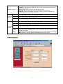
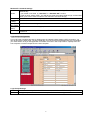
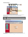
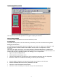
1
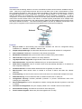
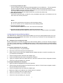
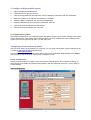
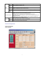
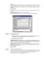
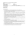
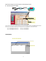
Desktop 10Base-T Internet ISDN Gateway User’s Manual 529930 I-ISS-020 Introduction The NexIP Internet Sharing Station is the most cost-effective Internet access solution available today for users. With only a single Internet account and a low cost dial-up line, it lets a small network of more than 2 desktop computers to share the vast resource available on the Internet simultaneously. Compare to traditional leased-line router configuration, the Internet Sharing Station is not only easier to use, it reduces ownership and maintenance cost dramatically with its innovative architecture. In dial-up configuration, it connects to remote Internet Service Provider (ISP) network automatically only when local users tried to access remote hosts on the Internet. To further improve performance when multiple users access the Internet at the same time, the Internet Sharing Station provides additional asynchronous ports with dial-on-demand functions. The Internet Sharing Station will dial up additional connections if the primary line is congested, so the Internet access performance can be improved instantly. Internet Features z Easy to Install. An auto-sensing LAN connection eliminates the need for configuration during installation in a 10BASE2 or 10BASE-T Ethernet LAN. z Simple Setup and Manage. Provides both Web browser and terminal interface for configuration. z Dial-on-Demand. Establishes connections to the Internet as required. z Bandwidth-on-Demand. Dial-up the second modem or ISDN TA only when needed. z Idles Time Out. Hangs up the modem if no activity detected. z High Speed Modem Supported. Supports 56K modem and 128K ISDN TA. z PPP Authentication. Automatically validates the log-on to Internet Service Provider. z DHCP Server Supported. Acts as a DHCP server and automatically allocates an IP address to each computer on the LAN. z Firewall Protection. Provides natural firewall and secure gateway for LAN users. z RAS Function. Allow remote users on outside or at home to dial-in and share the network resources. z E-mail Sharing. Lets one E-mail account on ISP’s mail server to be shared with multiple LAN users. z Status Monitoring. On-line checks the dial-up condition and the flow on each port. z Configuration Security. Provides password protection to prevent unauthorized users from modifying the configuration. z Remote Management. Can be managed from a station running Web browser anywhere on the LAN or Internet. z Virtual Servers Supported. Puts your company’s Web / FTP / TELNET servers on the Internet. z Phone Number Hunting. Provides two accounts for each dial-up line. z Flash Firmware Upgrade. Allows easy firmware upgrade via FTP utility. 1 Package Contents This package has: 1. One Internet Sharing Station 2. One power adapter 3. Wall Mounting kit 4. This user’s guide Hardware Introduction The components of the unit are shown as the following figure: Front Panel LED Status Table ON: DC power is on PWR OFF: No DC power FDX ON: Indicates communication on your LAN is operating at full-duplex mode. OFF: Indicates transmission mode is half-duplex. LNK ON: Ethernet interface is being connected. LAN OFF: Ethernet interface not connected ACT Blinking: Indicates traffic passing through the Ethernet port. OFF: No traffic ERR ON: Error condition OFF: Normal condition UTL (ON=1; OFF=0) Enumerate from left to right. When the WAN-1 port is connected to modem, and it is on idle state, the LEDs are used to indicate baudrate. When connection is established, the LEDs are used to indicate utilization. “000”- Port disconnected WAN-1 “100”- Baudrate=9.6K; or Utilization=20% “010”- Baudrate=19.2K “110”- Baudrate=38.4K; or Utilization=60% “001”- Baudrate=57.6K “101”- Baudrate=115.2K “011”- Baudrate=230.4K “111”- Baudrate= reserved; or Utilization=100% ERR ON: Error condition OFF: Normal condition UTL (ON=1; OFF=0) Enumerate from left to right. When the WAN-2 port is connected to modem, and it is on idle state, the LEDs are used to indicate baudrate. When connection is established, the LEDs are used to indicate utilization. “000”- Port disconnected WAN-2 “100”- Baudrate=9.6K; or Utilization=20% “010”- Baudrate=19.2K “110”- Baudrate=38.4K; or Utilization=60% “001”- Baudrate=57.6K “101”- Baudrate=115.2K “011”- Baudrate=230.4K “111”- Baudrate= reserved; or Utilization=100% 2 Install the unit This unit can be placed on a flat surface or mounted on a metallic surface or partition. Please comply with the following steps for proper installation. Desktop Installation y Carefully take out the unit from its packaging y You will find four self-adhesive rubber feet attached on the bottom of the unit, which provide space for ventilation and cushion the unit needed against vibrations. Place the unit directly on your desk. Magnetic Mounting Installation Inside each of the four rubber feet, you will find a magnetic ring. Adhere this unit to steel flat surface using the magnets on the bottom of the unit. y Wall Mounting Installation y There is a trough on the bottom of the unit, which is used for wall mounting. y Use two screws to mount the mounting track plate onto the wall. y Put the unit over the mounting track plate, and slide it to the suitable position. Screw Mounting Track Plate Connecting your equipment Internet Modem or ISDN-TA e d HUB e Internet Sharing Station f c 3 f e 1. Connecting the Ethernet cable. Connect a network cable to the Internet Sharing Station’s RJ-45 or BNC port. This unit supports two types of Ethernet cables: Thin Ethernet (10BASE2, BNC connector) and Twisted Pair Ethernet (10BASE-T, RJ-45 connector). During power up, the unit automatically detects the type of network cable and adjusts to that environment. Note: Please do NOT use both of BNC and RJ-45 connections simultaneously. 2. Connect your modem. Connect an external modem or ISDN TA, using a standard serial cable, to the WAN port on the back of the unit and to a phone line Notes: z Turn off the power before connecting or disconnecting modems. z You can connect up to two modems to the Internet Sharing Station 3. Connect the power adapter. Connect the power adapter to the units. The Power LED should light. 4. Connect the Internet Sharing Station and all of your PCs to hub Before proceeding this step, make sure each of your PCs has a network interface card installed. Configuring the Internet Sharing Station The easiest way to configure the Internet Sharing Station is to use your existing Web browser. Once you have set up your PC and installed web browser, you can launch your browser and view web pages from the Internet Sharing Station. Setting up PC to configure the web Before using browser to find the web pages from Internet Sharing Station, you have to manually configure your PC for TCP/IP networking. The DHCP server function of Internet Sharing Station is enabled defaultly, your PCs should be set to obtain an IP address automatically. This procedure is described in the following section. To configure a Windows NT 3.51 system 1. Open the Main group in Program Manager. 2. Open the Control Panel and open the Network icon. 3. Select TCP/IP Protocol within the Installed Network Software Window or install it if necessary. See your Windows documentation. 4. Click the Configure button and select the Adapter Type. 5. Check the Enable Automatic DHCP Configuration checkbox. 6. Type your computer name in the Host name box. Click OK to close the TCP/IP configuration window. 7. Click OK to close and restart your computer. To configure a Windows NT 4.0 system 1. Right-click Network Neighborhood and click Properties. 2. Click the Protocols tab and select the TCP/IP Protocol in the list. If TCP/IP does not appear, install it. See your Windows documentation. 3. Click the Properties button and select the adapter type. 4. Make sure “Obtain an IP Address from A DHCP Server” is selected. 5. Type your computer name in the Host name box. 6. Click OK on the bottom of the TCP/IP window. 7. Click OK to close and restart your computer. 4 To configure a Windows 95/98 system 1. Right-click Network Neighborhood. 2. Click Properties on the pop-up menu. 3. Click the Configuration tab and select the TCP/IP networking component and click Properties. 4. Make sure “Obtain an IP Address Automatically” is selected. 5. Select the DNS Configuration tab, and select Disable DNS. 6. Select the Gateway tab and remove any addresses. Click OK. 7. Click OK to close the Network Control window. 8. Click OK to close and restart your computer. To configure other systems See the documentation for your operating system and set the system up for TCP/IP. Configure the system to be a DHCP client. If the system doesn’t support DHCP, set an IP address that is not conflicted to that system and in the range from 192.168.0.1 to 192.168.0.252. Configuring the Internet Sharing Station After you finish setting up and restart your computer, you can open web browser, type the following in the Location (or Address) window, and press Enter. http://192.168.0.254 You should then see the first screen, which will prompt you for a password. Default password is “admin”, just type admin, then click OK to continue to the configure screen. Quick Configuration Simply connect modem to the WAN 1 port of the Internet Sharing Station, and complete all settings on this first page, then restart the Internet Sharing Station, and then restart all of the PCs, you are ready to access Internet. Basic Configuration 5 [The Station] IP Address: Network Mask: DHCP Server: Primary DNS: Secondar y DNS: IP address for the Internet Sharing Station. Use the default value (192.168.0.254) unless the address is already in use. The default value 255.255.255.0 is OK for small networks. Select “Enable” to enable the function of DHCP service for local LAN. Select “Disable” to disable the function of DHCP service Enter the DNS IP address (default value is 168.95.192.1) provided by your ISP. Enter the other DNS IP address provided by your ISP, if possible. Define the Internet account for the WAN 1 port. User ID.: Enter the account name provided by your ISP. Password: Enter the password for the corresponding account name. [Internet Account] Phone No.: Enter your ISP’s telephone number. Use the format described in your modem’s user manual. IP Address: Enter the IP address assigned to you by your ISP. For dynamic IP address assignment, the IP address is 0.0.0.0. Baudrate Assign the data transmission speed on the serial line of WAN 1. Available speeds are (bps) 9600, 19200, 38400, 57600, 115200, and 230400 bps [WAN 1] Teardown The period of idle time allowed when a connection is established. When timer Time expired, the connection will be disconnected. Advanced Configurations Network Configuration Network Settings: 6 [Internet Account] Baudrate (bps) Serial Port Teardown [WAN 1] Time Authentica tion Baudrate (bps) Teardown Time Authentica Serial Port tion [WAN 2] Activity Mode Define Internet accounts for each WAN 1 and WAN 2 ports. Phone No.: Enter your ISP’s telephone number. Use the format described in your modem’s user manual. User ID.: Enter the account name provided by your ISP. Password: Enter the password for the corresponding account name. IP Address: Enter the IP address assigned to you by your ISP. For dynamic IP address assignment, the IP address is 0.0.0.0. Assign the data transmission speed on the serial line of WAN 1. Available speeds are 9600, 19200, 38400, 57600, 115200, and 230400 bps The period of idle time allowed when a connection is established. When timer expired, the connection will be disconnected. The allowed password checking protocols in PPP authentication phase. (defaults to select both) Assign the data transmission speed on the serial line of WAN 2. Available speeds are 9600, 19200, 38400, 57600, 115200, and 230400 bps The period of idle time allowed when a connection is established. When timer expired, the connection will be disconnected. The allowed password checking protocols in PPP authentication phase. (defaults to select both) Disable: WAN 2 will always be disabled Bandwidth-on-Demand (BoD): WAN 2 will be activated only when WAN 1’s bandwidth is full-load. Always: WAN 2 will always be activated when the first client accesses the Internet. RAS-Port: WAN 2 acts as a RAS port that allows user remote dial-in. Modem Configuration 7 Modem AT Command Settings If your model is listed, simply select it , then the modem initial string will be configured automatically. If your model is not listed, try “Standard” or “Standard 56K” modem Model: If it still not work, select “Other”. You will have to enter the modem initial strings, as described below. (You have to refer to modem’s user manual to set these strings) Initial String: Specifies the command to configure your modem or ISDN TA correctly Auto-Answe Specifies the command to set the modem or ISDN TA’s auto-answer mode r String: Escape Specifies the code to change modem from data transmission to AT command mode Seq. Code: Hang-Up Specifies the command to hang-up phone call for modem String: Specifies the command (sometimes called “Dial Prefix String”) to dial a phone call for modem Dial String: or ISDN TA Login Script Configuration If your ISP uses a scripting process for logging onto the network before starting a PPP connection, you can do this with the login script. The login script lets you write a script that automatically logs in and starts your PPP session as if you had typed the commands. Each line in the script waits for a prompt from the host computer or sends a response to the host computer. Login Script Settings Enable Set “YES” to run script file before PPP takes over; set “NO” to run PPP directly Line## The login script commands and some examples are described on Appendix A 8 Email Sharing Configuration The usage of Email sharing allows one Email account shared with multiple users. The [Mail Server Account] specifies the shared Email account, and the [Local User Account] specify the sharing users. The detail configurations to some popular Email clients such as “Outlook”, “Eudora”, and “Netscape Messenger” are described on Appendix B. Remote Access Service Configuration Configures WAN 2 as RAS-Port Internet pc1 pc2 192.168.0.254 RAS-Port 192.168.0.1 Internet Sharing Station 192.168.0.2 192.168.0.253 Support Network Neighborhood All allowed dial-in users are defined as E-mail Sharing users as described previous page. In this case, the allowed users are supervisor, pc1, pc2, pc3, pc4, pc5, pc6, and pc7. Note that the auto-answer mode should be enabled on the modem that connects to WAN 2, i.e., in the modem configuration on WAN 2 port, the Auto-Answer-String should be set to “ATS0=x”, where x is a number which large than or equal to 1. 9 Virtual Server Configuration Internet Sharing Station Internet CHAT Server (192.168.0.10) WWW Server (192.168.0.1) FTP Server (192.168.0.2) Telnet Server (192.168.0.3) External port on IS020 Any incoming IP packets send to the external port will redirect to this internal server on this port This shows the internal servers that allowed to be accessed through the Internet Sharing Station from Internet. Type 0.0.0.0 will prevent the Internet users from accessing the internal servers. Virtual Server settings FTP Server: Specifies the IP address of the computer that will act as FTP server on your local LAN Telnet Server: Specifies the IP address of the computer that will act as Telnet server on your local LAN WWW Specifies the IP address of the computer that will act as WWW server on your local LAN Server: Console Password Configuration The current password can be changed, the new password will be required for the next time that you want to configure the unit. 10 Firmware Upgrade Procedure You may follow the procedure specified in this page to update your firmware. Reset to Factory Default This feature let all configurations return to the initial factory value. System Restart If complete all configurations, the new values may effect after you restart the Internet Sharing Station. Setting up the other PCs Once the Internet Sharing Station has been configured on your LAN, it is ready for use. However, all of the PCs must have a network interface card installed, and they must be configured for TCP/IP networking. You have to set up all of the PCs on your LAN to be DHCP clients that will obtain an IP address from Internet Sharing Station automatically. The following describes how to configure your Win95 station to be a DHCP client. For other operating systems, see Setting up PC to configure web. 1. Right-click Network Neighborhood. 2. Click Properties on the pop-up menu. 3. Click the Configuration tab and select the TCP/IP networking component and click Properties. 4. Make sure “Obtain an IP address automatically” is selected, like the following. 5. Select the DNS Configuration tab, and select Disable, but the fields can be left blank. 6. Select the Gateway tab and remove any addresses. Click OK. 7. Click OK to close the Network Control window. 8. Click OK to close and restart your computer, and you can access Internet. 11 Note: 1 Once the Internet Sharing Station has been configured, all of the PCs should be restarted to get the new TCP/IP settings from the Internet Sharing Station. 2 After restarting your computer, please make sure your computer has obtained an IP address, DNS and Gateway IP address(192.168.0.254). Customizing TCP/IP settings The Internet Sharing Station is preconfigured for installation on a network that is not set up for TCP/IP. It uses a range of private IP addresses in a range from 192.168.0.1 to 192.168.0.254, with the address of the Internet Sharing Station preset to 192.168.0.254. If you have already set up the TCP/IP protocol on your network, you can customize the Internet Sharing Station to fit your existing IP policy. To customize TCP/IP settings for your existing network 1. Configure one of your PCs to be a DHCP client, and restart it, then your PC will obtain an IP address automatically from Internet Sharing Station. 2. From the selected computer, launch web browser and connect to the Internet Sharing Station web page (http://192.168.0.254), if the system on your network already have public IP addresses, set ‘DHCP Server:’ to “Disable”, then click “Save” button. 3. Change the Internet Sharing Station’s IP Address to the address that is valid for your network, then click “Save” button, and then click ‘System Restart’ to restart the Internet Sharing Station. 4. Change the IP address of the selected computer back to its original setting. 5. Make sure the Gateway IP address of all PCs must be same as the Internet Sharing Station’s IP address, DNS must be enabled, and DNS IP address(es) must be assigned. Troubleshooting Troubleshooting gives you solutions to problems that may occur during installation and operation of the Internet Sharing Station. 1. Problem: No power to the Internet Sharing Station Possible Cause: Solution: 2. Problem: Solution: The power adapter is a defective one. Check the power cord and power outlet to verify its connection. If it still remains unlit, please replaced another power adapter. Can’t connect to the Internet Sharing Station 1. Check the TCP/IP setup on your PC. On Windows 95/98: Run winipcfg from Run on the Start menu. The PC should have an IP address of 192.168.0.n, where n is from 1 to 252. The Gateway IP address of the PC must be 192.168.0.254. If the IP address is not in the range, click Release then click 12 Renew. On Windows NT: Type ipconfig from the command prompt. The PC should have an IP address of 192.168.0.n, where n is from 1 to 252. The Gateway IP address of the PC must be 192.168.0.254. If the IP address is not in the range, type the following commands: ipconfig / release ipconfig / renew 2. If you have used proxy on the browser, make sure it has 192.168.0.254 as an exception In Internet Explorer: Add 192.168.0.254 as an exception In Netscape Navigator: Add 192.168.0.254 as an exception, mentioned as follow. 3. Problem: Solution: Can’t connect to the Internet 1. Check the phone link y Check the phone line. If it’s a regular analog line, connect a telephone and see if you get a dial tone. Dial your ISP number to see if you get a modem tone. y Is a 9 required for an outside line ? 2. Check the TCP/IP setup on your PC. On Windows 95/98: Run winipcfg from Run on the Start menu. The PC should have an IP address of 192.168.0.n, where n is from 1 to 252. The Gateway IP address of the PC must be 192.168.0.254, and the DNS Server address(es) must not be empty. If the IP address is not in the range, click Release then click Renew. On Windows NT: Type ipconfig from the command prompt. The PC should have an IP address of 192.168.0.n, where n is from 1 to 252. If the IP address is not in the range, type the following commands: ipconfig / release ipconfig / renew 4. Problem: Solution: Can not communicate with the ISP. 1. This is mostly likely a problem due to the fact that your baudrate setting is too high for your modem or ISDN TA. Sometimes the maximum baudrate that your modem or ISDN TA claims it can achieve is not really attainable because of phone line quality 2. Talk to your ISP to see if the login script is required. 13 5. Problem: My Modem/ISDN TA is working fine with my PC running Windows 95. How do I find its initial string ? Solution: 1. Select My Computer, then Dial-Up Networking. 2. Select the icon for your connection, then properties. 3. Click the Configure button, then Connection tab. 4. Select Advanced , then check the option Record a log file, click OK and exit. 5. Use Dial-up Networking to make your on-line connection normally. A log file MODEMLOG.TXT will be created in your Windows directory. 6. Examine the file to determine the Initial String, 14 Specifications Standards and Protocols IEEE 802.3 10BASE-T and 10BASE2 TCP/IP, PPP, CHAP/PAP/MS-CHAP, DHCP Operational Characteristics LAN port: 10BASE2/10BASE-T auto sensing WAN speed: 230.4Kbps max. DTE speed Power Characteristics External Power Adapter: Input Voltage: 100VAC, 60Hz / 120VAC, 60Hz / 230VAC, 50Hz / 240VAC, 50Hz Output Voltage: 9 VDC, 1 A Physical Characteristics Number of ports: 1 x 10BASE-T/10BASE2, 2 x RS-232 Panel indicators: PWR, Link, Activity, Full Duplex, Error, Utilization/Baudrate Weight: Dimensions: Temperature: Operating: Storage: Humidity: Approvals: EMI: Safety: 0.28 kg 135 x 104 x 35 mm (L x W x H) 0℃ to 40℃; – 20℃ to 70℃ 5% to 95% (non-condensing) FCC Class B,VCCI Class B, CISPR 22 Class B TÜV/GS, UL, cUL Regulatory Standards Compliance EMI Information FCC Class B (For USA Only) FCC ID: NUKISCCM020 This device complies with Part 15 of the FCC Rules. Operation is subject to the following conditions: 1. This device may not cause harmful interference, and 2. This device must accept any interference received, including interference that may cause undesired operation. Warning! This equipment has been tested and found to comply with the limits for a Class B digital device, pursuant to Part 15 of the FCC Rules. These limits are designed to provide reasonable protection against harmful interference in a residential installation. This equipment generates, uses and can radiate radio frequency energy and, if not installed and used in accordance with the instructions, may cause harmful interference to radio communications. If this equipment does cause harmful interference to radio or television reception, which can be determined by turning the equipment off and on, the user is encouraged to try to correct the interference by one or more of the following measures: • Reorient or relocate the receiving antenna • Increase the separation between the equipment and receiver • Connect the equipment into an outlet on a circuit different from the one which the receiver is connected to • Consult the dealer or an experienced radio/TV technician for help You are cautioned that changes or modifications not expressly approved by the party responsible for compliance could void your authority to operate the equipment. You may use unshielded twisted-pair (UTP) for RJ-45 connections. VCCI Class B (For Japan Only) 15 CE Mark Declaration of Conformity for EMC and Safety(EEC) EMC: EN55022 (1994)/CISPR 22 (1993) class B IEC 1000-4-2 (1995) 4kV CD, 8kV AD IEC 1000-4-3 (1995) 3V V/m IEC 1000-4-4 (1995) 1kV - (power line) , 0.5kV - (signal line) This product complies with the requirements of the Low Voltage Directive 73/23/EEC and the EMC Directive 89/336/EEC Safety Compliance EN60950, UL 1950 Sicherheitshinweise 1. Die Steckdose muß sich in der Nähe des Gerätes befinden und leicht zugänglich sein. 2. Zum Reinigen den Stecker aus der Steckdose ziehen. Beim Reinigen keine Flüssigreiniger oder Sprays verwenden, sondern ein angefeuchtetes Tuch. 3. Das gerät nicht in Naßräume oder in der Nähe von Wasser benutzen, wie z.B. Badezimmer, Schwimmbad, Spülbecken usw. . Das Eindringen von Wasser kann zur Zerstörung des Gerätes führen. 4. Das gerät nicht auf einer unstabilen Unterlage, wie z.B. Rollwagen, Gestell usw., aufstellen. Es könnte herunterfallen und Verletzungen oder Beschädigungen von Mensch und Gerät verursachen. 5. Die Belüftungsöffnungen nicht blockieren oder auf falscher Ober-fläche, wie Bett, Sofa usw., stellen. Durch die Blockierung kann es zur Zerstörung des Gerätes durch Überhitzung kommen. 6. Versuchen Sie niemals dieses Gerät selbst zu warten, da beim Öffnen oder Abnehmen des Gehäuses die Gefahr eines elektrischen Schlages besteht. 7. Keine Gegenstände auf das Anschlußkabel stellen, damit es nicht durch scharfe Kanten zerstört werden kann. 8. Keinerlei Gegenstände durch die Öffungen in das Gerät stecken, da es dadurch sonst zu Kurzschlüssen kommen kann. 9. Bei Störungen des Gerätes den Wartungsdienst verständigen. 10. Bei Reperaturen dürfen nur Orginalersatzteile oder Bauteile mit gleichen Eigenschaften verwendet werden. Andere Bauteile können Feuer, elektrischen Schlag oder andere Gefahren verursachen. 11. Nach Beendigung von Wartungsarbeiten oder Reperaturen durch den Kundendienst sollte die Sicherheitsprüfung durchgeführt werden. 12. Bei längerem Stillstand des Gerätes, ist diese von der Versorgungs- spannung zu trennen. Dies verhindert eine Beschädigung des Gerätes durch eine Überspannung in der Zuleitung. 13. Der arbeitsplatzbezogene Lärmschutzpegel nach DIN 45 635 ist kleiner 70dB (A). 16 Appendix A: Login Script Files This section describes the script file commands and syntax to be used when editing script files. Script file is only required if your ISP does not use a standard PPP negotiation. Learn the script syntax Five commands can be used to automate a proprietary negotiation process. The commands are as follows: send “<string>” Send a data string and then go to next line 1. wait “<string>” Wait to receive a data string, and then go to next line send_id Send user name send_passwd Send password corresponding to the user hangup Hang Up Modem run or run_ppp Start to run PPP and ignore rest of script Example of the Login Script File Scenario Your ISP instructs you to log in and issue a PPP command. The system prompts for a login and password. After the ISP’s host sends a welcome message, you enter the “ppp” command. If you logged in manually with a username of “juns” and a password of “1234”, it would look like this: Enter username: juns Enter password: 1234 Welcome to Hinet! ppp Script for this scenario Your script should look like this: Wait “:” Send “juns” Wait “:” Send “1234” Wait “!” Send “ppp” Run_ppp Note: You only need to include the last specific character in the text, in this case “!” in “Welcome to Hinet!” 2. Script file used for CompuServe The following is the login script used to log on to CompuServe. Send Send “CIS” Wait “:” Send_id Wait “:” Send_passwd Wait “!” Send “GO PPPCONNECT” Run_ppp 17 Appendix B: Configure Your E-mail Clients For E-mail Sharing Function Email Sharing Operation Model Internet pc1 pc2 192.168.0.254 Email Server: Host name: ms25.hinet.net User name: unextest Password : xxxxxxxx E-mail setting on pc1 (or pc2) : User name: pc1 (or pc2) Password: xxxx Incoming POP3 server: 192.168.0.254 Outgoing SMTP server: ms25.hinet.net Send mail to pc1 : 1. pc1<[email protected]>, or 2.”pc1”<[email protected]> In this case, E-mail sharing function allows your ISP E-mail address called [email protected] be shared by PC1 and PC2, so that they can have their own e-mail address, mentioned as follow: “pc1”<[email protected]> “pc2”<[email protected]> For PC1’s e-mail address For PC2’s e-mail address Outlook Express Step 1: Select Tools->Accounts->Mail 1. Select one account 2. Press “Properties” button 18 Step 3: Fill in the incoming and outgoing mail server The real mail server The IP address of Internet Sharing Station The user name defined in Internet Sharing Station The password for this user on Internet Sharing Station Netscape Messenger Step 2: Fill in aliases name and real email address Select the user name defined in IS020 The shared E-mail account 19 Step 1: Select Edit->Preferences->Mail & Newsgroup->Identity Select the user name defined in Internet Sharing Station The shared E-mail account Step 2: Fill in the incoming and outgoing mail server The IP address of Internet Sharing Station The real mail server The user name defined in Internet Sharing Station 20 Step 3: ->Select 192.168.0.254->Edit Select “POP3 Server” as the mail receiving protocol The user name defined in Internet Sharing Station Eudora 1.5.4 ~ 3.x.x Step 1: Select Tools->Options->Getting Started Select the email account on Internet Sharing Station Select the user name defined in Internet Sharing Station 21 Step 2: Tools->Options->Sending Mail The shared E-mail account The real mail server Eudora 4.x.x and above Step 1: Select Tools->Options->General Select the user name defined in Internet Sharing Station The shared E-mail account The IP address of Internet Sharing Station Select the user name defined in Internet Sharing Station The real mail server 22 23