1
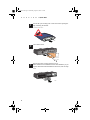
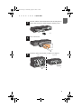
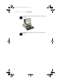
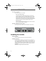
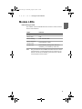
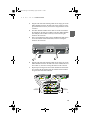
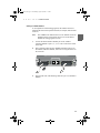
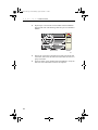
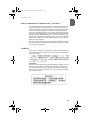
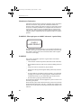
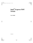
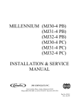
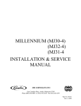
1000SX Advanced Module
for 500 Series Switches
User Guide
A23295.book Page i Wednesday, August 30, 2000 1:16 PM
1000SX Advanced Module
for 500 Series Switches
User Guide
A23295-001
A23295.book Page ii Wednesday, August 30, 2000 1:16 PM
Copyright © 2000, Intel Corporation. All rights reserved.
Intel Corporation, 5200 NE Elam Young Parkway, Hillsboro, OR 97124-6497
Intel Corporation assumes no responsibility for errors or omissions in this manual. Nor does Intel make any commitment to update the information contained herein.
*
Other product and corporate names may be trademarks of other companies and are used only for explanation
and to the owners’ benefit, without intent to infringe.
First edition
October 2000
A23295-001
A23295.book Page 1 Wednesday, August 30, 2000 1:16 PM
1
Quick Start
Warning for 1000SX Advanced
This product contains fiber-optic ports. For optical safety, never look directly at, or use optical instruments on, the fiber TX laser port and fiber
cable ends when they are powered-up. The module’s optical ports must
be terminated either with an optical connector or a dust plug.
CLASS 1
LASER PRODUCT
Installing the module
Follow these instructions to install a 1000SX Advanced Module in your
Intel® Express 500 Series Switch:
Warning
This module is not designed to be installed in, or
removed from, the switch while it is in operation. You
must turn off the switch before installing or removing the
module. Failure to do this may result in the module not
being able to communicate with the switch.
1
A23295.book Page 2 Wednesday, August 30, 2000 1:16 PM
C
H
A
P
T
1
E
R
1 Quick Start
Ensure that your working area is static-free before opening the
bag containing the module.
Electrostatic Sensitive Device
1757
5042
2
Turn off the switch.
5043
3
Remove the plate covering expansion slot A.
If the module is to be installed in a stack with redundancy or you
require information about installation restrictions, refer to Chapter 2.
5044
2
A23295.book Page 3 Wednesday, August 30, 2000 1:16 PM
C
H
A
P
T
4
E
R
1 Quick Start
Insert the 1000SX Advanced Module into the slot and push it in
until it clicks. Secure the module using the retaining screws.
5045
5
Turn on the switch.
5046
6
Attach the cables to the module. For details, see Chapter 3.
Stack
or
Single switch
Server
or switch
Server
or switch
3100
3
A23295.book Page 4 Wednesday, August 30, 2000 1:16 PM
C
H
A
P
T
7
E
R
1 Quick Start
Configure the module using Intel Device View. For details, see
Chapter 4.
3101
8
4
Verify the links using the LEDs. For details about LEDs, see
Chapter 2.
A23295.book Page 5 Wednesday, August 30, 2000 1:16 PM
2
Getting to know the
Module
Introduction
When to use the module
The 1000SX Advanced Module (ES500MSXA) can only be used with
Intel Express 500 Series Switches. It provides a high-speed link between the switch or group of switches containing this module and another device, switch or group of switches. The 1000SX Advanced Module
supports the IEEE 802.1Q standard and the Gigabit standard IEEE
802.3, 1998.
Supporting the IEEE 802.1Q standard enables the switch, or stack, containing this module to handle both tagged and untagged frames, ensuring that they are forwarded to the correct destinations.
5
A23295.book Page 6 Wednesday, August 30, 2000 1:16 PM
C
H
A
P
T
E
R
2 Getting to know the Module
Two modes of operation
This module operates in two modes.
•
Stack mode (default setting):
Used when the switch containing this module is connected to a
group of switches (or stack) via a Matrix Module. The two Stack
Interface Module (SIM) connectors enable the module to be integrated into the group of switches (even a stack with redundancy).
The fiber optic SC connector provides the high-speed link between
the group of switches (or stack) and another stack or device.
•
Stand-alone mode:
Used to provide a high-speed link between the switch and another
device via the fiber optic SC connector.
View of the 1000SX Advanced front panel
The front panel of the 1000SX Advanced Module is shown below:
1000SX Advanced Module for 500 Series Switches
CLASS 1 LASER PRODUCT
Stack Interface Module
1000Base-SX
TX
RX
5001
Installing the module
General Installation
General installation instructions are described in Chapter 1.
Installation restrictions
In a stack without redundancy, this module must not be installed in a
switch containing a Stack Interface Module, a 155 ATM Module, or another 1000Base Module. In certain circumstances, this module can be
installed in the same switch as a Matrix Module. These circumstances
are described in the Matrix Module User Guide. The latest version is
available at:
http://intel.com/support/express/switches/500/
6
A23295.book Page 7 Wednesday, August 30, 2000 1:16 PM
C
H
A
P
T
E
R
2 Getting to know the Module
Installation in a stack with redundancy
Install the module on the same side of the switch as the Matrix Module
it is to be connected to (for example both modules in Slot A). When possible, do not install this module in the same switch as a Matrix Module.
This prevents having a single point of failure.
Both 1000Base modules must have the same tagging mode settings.
IEEE 802.1 Q VLANs via this module
Introduction
Using this module as the entry point from devices that support IEEE
802.1 Q, allows 802.1 Q VLANs to be mapped to VLANs in the Express
500 series switches, which do not support the IEEE 802.1 Q standard.
When installed in a stack, this module makes available the mapping information to all the 500 series switches in the stack.
Mapping works in both directions. Frames coming from the 802.1Q environment are recognized using their tags and forwarded to the correct
destination. Frames originating from members of a VLAN in the Express 500 series switches, have a tag inserted when leaving the module
for members of mapped VLANs in the 802.1 Q environment.
This recognition of tagged frames can be enabled and disabled in the
module. This is done in the Module Mode dialog, and is described in
Chapter 4.
Note
When 802.1 Q tagging is disabled, all tagged frames received
on all switch ports are forwarded without tag recognition.
However, when 802.1 Q tagging is enabled, only tagged
frames received on the module’s 1000Base port are forwarded. Tagged frames received on the switches’ front ports
are discarded.
The following sections apply to the module when IEEE 802.1 Q tagging
recognition is enabled.
Mapped VLANs between 500 series switches and IEEE 802.1 Q devices
Each Express 500 series switch VLAN name is mapped to a unique
802.1.Q VLAN ID. These mapped VLANs must also have a priority assigned.
Note that these VLANs can only be mapped one-to-one.
Overlapping VLANs
This module only supports one VLAN per MAC address. Therefore, the
following conditions must be observed:
7
A23295.book Page 8 Wednesday, August 30, 2000 1:16 PM
C
H
A
P
T
E
R
2 Getting to know the Module
Proprietary 500 series VLANs
Overlapping proprietary VLANs may cause a problem if more than one
of the VLANs are mapped to a 802.1 Q VLAN. Failure to adhere to this
may lead to connectivity problems.
802.1 Q VLANs
Stations in the 802.1 Q environment that are members of more than one
VLAN may experience connectivity problems if more than one of the
VLANs are mapped to a proprietary 500 series VLAN. Therefore, it is
recommended that overlapping 802.1 Q VLANs are not mapped to proprietary 500 series VLANs.
However, if a station must be a member of more than one 802.1 Q
VLAN and be mapped to a proprietary 500 series VLAN, then by making an IP or MAC policy for the station and including this as a permanent entry, the connectivity problems may be avoided.
VLAN policy restrictions
VLANs defined using Port Policies are not supported by this module.
Although MAC policies and IP policies are supported, they are only
useful for stations (in the 802.1 Q environment) that are members of
more than one 802.1 Q VLAN (see Overlapping VLANs).
NOTE: Permanent entries are supported, but IP or MAC Policies must
be created to use them. This is because no real learning occurs on permanent entries.
Multiple Spanning Tree Protocol
Multiple STP is supported by this module with the following condition:
only one VLAN per port is permitted when Multiple STP is enabled.
8
A23295.book Page 9 Wednesday, August 30, 2000 1:16 PM
C
H
A
P
T
E
R
2 Getting to know the Module
Module LEDs
Understanding the LEDs
The 1000SX Advanced Module has three connectors. Each connector
has two LED indicators:
Status
Indicates
No lights
Port enabled, no link.
Green, solid
Link.
Green, blinking
Link with data traffic.
Green, solid and
Orange, solid
Port disabled by a fault.
Orange, solid
Note
Port disabled by management; backup in
redundancy (no redundancy with 510T).
The green LED for the 1000Base-SX SIM connector remains
solid when there is a link with data activity. Data activity on
this link is shown by the blinking, green LED next to the SC
connector (RX and TX sockets).
9
A23295.book Page 10 Wednesday, August 30, 2000 1:16 PM
C
10
H
A
P
T
E
R
2 Getting to know the Module
A23295.book Page 11 Wednesday, August 30, 2000 1:16 PM
3
Cable the module
Introduction
The cabling and configuration of the 1000SX Advanced Module are
very closely linked. Only after both processes are complete will the
switch function properly. Configuring the module is described in Chapter 4.
Cabling the module
Introduction
The cable connections to the module depend on the mode in which the
module is to be used. The mode is set using Intel Device View, see
Chapter 4.
11
A23295.book Page 12 Wednesday, August 30, 2000 1:16 PM
C
H
A
P
T
E
R
3 Cable the module
Stand-alone Mode
Cabling for a single switch
Follow these instructions to provide a high-speed (1000Base-SX) link
between the switch containing the 1000SX Advanced Module and another switch, device or group of switches:
Warning
1
When used in stand-alone mode, this module must not be
installed in a switch containing a Stack Interface Module,
a Matrix Module or a 1000Base Module set in stack
mode.
Plug the SC connectors on the optic fiber cable into the RX and
TX sockets on the 1000Base-SX connector.
1000SX Advanced Module for 500 Series Switches
CLASS 1 LASER PRODUCT
1000Base-SX
Stack Interface Module
5004
2
12
Plug the other end of the cable into a device and check the LEDs
on the 1000SX Advanced Module to verify the link. For information on the LEDs, see Chapter 2.
A23295.book Page 13 Wednesday, August 30, 2000 1:16 PM
C
H
A
P
T
E
R
3 Cable the module
Stack Mode
Cabling to a Matrix Module in a group of switches
The 1000SX Advanced Module is installed in a different switch from
the Matrix Module, so the cabling process is in two parts; the switch
containing the 1000SX Advanced Module must be connected to the
group, then the high-speed link between this group and another group or
device is established.
1
Plug the Stacking Cable (Intel Order Code: ES500SC) into the
Stack Interface Module connector on the 1000SX Advanced
Module, and secure it using the latches on the connector.
1000SX Advanced Module for 500 Series Switches
CLASS 1 LASER PRODUCT
Stack Interface Module
1000Base-SX
5006
2
Plug the other end of the Stacking Cable into the Matrix Module,
and secure it using the latches on the connector.
3
Plug a second Stacking Cable into the 1000Base-SX SIM connector on the 1000SX Advanced Module, and secure it using the
latches on the connector.
1000SX Advanced Module for 500 Series Switches
CLASS 1 LASER PRODUCT
1000Base-SX
Stack Interface Module
5008
4
Plug the other end of the Stacking Cable into the Matrix Module,
and secure it using the latches on the connector.
13
A23295.book Page 14 Wednesday, August 30, 2000 1:16 PM
C
H
A
P
T
E
5
R
3 Cable the module
Plug the SC connectors on the optic fiber cable into the RX and
TX sockets, and connect the other end of the cable to a device.
5
4
6
Module
Status
Matrix Module for 500 Series Switches
Link
1
2
Status
Internal Port
3
1000SX Advanced Module for 500 Series Switches
CLASS 1 LASER PRODUCT
1000Base-SX
Stack Interface Module
Server
5047
6
Check the LEDs on the 1000SX Advanced Module to verify the
links. For more information on LEDs, see Chapter 2.
Cabling to a Matrix Module in a stack of switches with redundancy
To provide total redundancy for the high-speed link, two 1000SX Advanced Modules are necessary. We recommend that you install these in
different switches from the Matrix Modules.
Note
Redundancy is not possible with the 510T.
1
Connect the Matrix Modules to the Stack Interface Modules in the
primary and secondary switches as described in the Matrix Module User Guide.
2
Plug a Stacking Cable (Intel Order Code: ES500SC) into the
Stack Interface Module connector on the 1000SX Advanced
Module, and secure it using the latches on the connector.
1000SX Advanced Module for 500 Series Switches
CLASS 1 LASER PRODUCT
Stack Interface Module
1000Base-SX
TX
RX
5048
Stacking Cable
connected to
the Matrix Module
14
A23295.book Page 15 Wednesday, August 30, 2000 1:16 PM
C
H
A
P
T
E
R
3 Cable the module
3
Plug the other end of the Stacking Cable into an empty port on the
Matrix Module located on the same side of the switch (for example, both modules in Slot A), and secure it using the latches on the
connector.
4
The Stack Interface Module in the other slot on this switch must
be plugged into the same port number in the other Matrix Module
(for example, both modules in slot B), and secured using the
latches on the connector.
5
Plug a second Stacking Cable into the 1000Base-SX SIM connector on the 1000SX Advanced Module, and secure it using the
latches on the connector.
1000SX Advanced Module for 500 Series Switches
CLASS 1 LASER PRODUCT
Stack Interface Module
1000Base-SX
5008
6
Plug the other end of the Stacking Cable into an empty port on the
Matrix Module located on the same side of the switch (both modules in Slot A), and secure it using the latches on the connector.
7
Repeat steps 2 through 6 for the second 1000SX Advanced Module, ensuring that the cabling from this 1000SX Advanced Module goes to the other Matrix Module.
Primary
Slot A
5
4
Secondary
Slot B
6
Slot A
Stack Interface Module for 500 Series Switches
Port Status
Matrix Module for 500 Series Switches
Intel Express
550T Routing
Switch
Status
1
2
Slot B
5
4
Stack Interface Module for 500 Series Switches
6
Port Status
Matrix Module for 500 Series Switches
Power
RPS
3
4
5
6
7
8
1
1
2
3
4
6
RPS
7
8
Reset
Console
9600-8-N-1
Slot A
Slot B
1000SX Advanced Module for 500 Series Switches
Stack Interface Module for 500 Series Switches
CLASS 1 LASER PRODUCT
Port Status
Stack Interface Module
Intel Express
550T Routing
Switch
Status
Power
Temperature
RPS
2
3
2
5
9600-8-N-1
1
Power
Temperature
Reset
Console
1000Base-SX
Intel Express
550T Routing
Switch
Status
Temperature
3
2
1
3
4
5
6
7
8
Reset
3
Console
9600-8-N-1
Slot A
Slot B
1000SX Advanced Module for 500 Series Switches
Stack Interface Module for 500 Series Switches
CLASS 1 LASER PRODUCT
Port Status
Stack Interface Module
1000Base-SX
Intel Express
550T Routing
Switch
Status
Power
Temperature
RPS
1
2
3
4
5
6
7
8
Reset
4
Console
9600-8-N-1
Slot A
Slot B
Stack Interface Module for 500 Series Switches
Stack Interface Module for 500 Series Switches
Port Status
Connects to
Matrix Module in
primary switch
Intel Express
550T Routing
Switch
Status
Power
Temperature
RPS
1
2
3
4
5
6
7
8
Reset
5
Console
9600-8-N-1
Slot A
Slot B
Stack Interface Module for 500 Series Switches
Stack Interface Module for 500 Series Switches
Port Status
Intel Express
550T Routing
Switch
Status
Power
Temperature
RPS
1
2
3
4
5
6
7
8
Connects to
Matrix Module in
secondary switch
6
Reset
Console
9600-8-N-1
5049
15
A23295.book Page 16 Wednesday, August 30, 2000 1:16 PM
C
H
A
P
T
E
R
3 Cable the module
8
Plug the SC connectors on the fiber optic cables into the RX and
TX sockets, and connect the other end of the cables to a device or
group of switches with redundancy.
9
Use Intel Device View to ensure that the mode settings for the two
1000SX Advanced Modules are the same.
10
Check the LEDs on the 1000SX Advanced Modules to verify the
links. For more information on LEDs, see Chapter 2.
Combine bandwidth on two modules
Introduction
Two modules installed on the same side of separate switches in a stack
(for example, both modules in Slot A) can have their bandwidth combined (known as link aggregrated) to increase the bandwidth between
this stack and another device or stack.
Note
The two modules must have the same mode settings for link
aggregation to work properly. Mode settings can be checked
and changed using Intel Device View, see Chapter 4.
Prevent network loops
Link aggregation must be configured in Intel Device View to prevent a
loop (see Chapter 4). When two modules are installed in a stack and
connected to another single device or stack (without redundancy or link
aggregation), then a loop may be created. Note that even with spanning
tree enabled, a delay of 10 to 15 seconds may occur before the loop is
discovered.
Note
16
The 1000SX Advanced Module connected to port 3 on the
Matrix Module must be configured as the anchor port.
A23295.book Page 17 Wednesday, August 30, 2000 1:16 PM
C
H
A
P
T
E
R
3 Cable the module
Cabling to a Matrix Module
To accomplish successful link aggregation, the modules must be installed on the same side of separate switches (for example, both modules
in Slot A).
Note
The 1000Base-SX SIM connectors on the 1000SX Advanced
Modules must be connected to ports 2 and 3 on the Matrix
Module for link aggregation to work.
1
Connect the Stack Interface Module port on the 1000SX
Advanced Module to ports 1, 4, 5, or 6. This connects the switch
to the stack.
2
Plug a Stacking Cable into the 1000Base-SX SIM connector on
the 1000SX Advanced Module, and secure it using the latches on
the connector.
1000SX Advanced Module for 500 Series Switches
CLASS 1 LASER PRODUCT
1000Base-SX
Stack Interface Module
5008
3
Plug the other end of the Stacking Cable into port 3 on the Matrix
Module.
17
A23295.book Page 18 Wednesday, August 30, 2000 1:16 PM
C
H
A
P
T
4
E
R
3 Cable the module
Repeat steps 1 and 2 for the second 1000SX Advanced Module.
Plug the other end of the Stacking Cable into port 2 on the Matrix
Module.
4
5
6
Module
Status
Matrix Module for 500 Series Switches
Link
1
2
3
Status
Internal Port
1000SX Advanced Module for 500 Series Switches
CLASS 1 LASER PRODUCT
Stack Interface Module
1000Base-SX
1000SX Advanced Module for 500 Series Switches
CLASS 1 LASER PRODUCT
1000Base-SX
Stack Interface Module
Server
5050
18
5
Plug the SC connectors on the fiber optic cables into the RX and
TX sockets, and connect the other end of the cables to a device or
group of switches.
6
Check the LEDs on the 1000SX Advanced Modules to verify the
links. For more information on LEDs, see Chapter 2.
A23295.book Page 19 Wednesday, August 30, 2000 1:16 PM
4
Configure the module
Introduction
The configuration and cabling of the 1000SX Advanced Module are
very closely linked. Only after both processes are complete will the
switch function properly.
Note
When the module mode is changed, the configuration is automatically saved and Intel® Device View resets the switch.
19
A23295.book Page 20 Wednesday, August 30, 2000 1:16 PM
C
H
A
P
T
E
R
4 Configure the module
Configuring the module
To change the module mode using Intel Device View
The default settings for the Module Mode is Stack Mode and 802.1Q
VLAN tagging disabled. With the switch containing the 1000SX Advanced Module displayed in the Device View window:
Warning
1
Right-click the 1000Base-SX port on the module and select Port
Setup.
2
Click the Module tab.
3
Select the correct modes.
Note
4
20
Changing mode causes Intel Device View to save the
switch configuration and reset the switch.
When 802.1 Q tagging is disabled, tagged frames
received on all ports are forwarded without recognizing the tag. When 802.1 Q is enabled, only tagged
frames received on the module’s 1000Base port are
recognized. Tagged frames received on the front ports
of the switch are discarded.
Click OK. The configuration is saved and the switch reset.
A23295.book Page 21 Wednesday, August 30, 2000 1:16 PM
C
H
A
P
T
E
R
4 Configure the module
To change the port settings using Intel Device View
The module’s 1000Base SX default port settings are; Port Enabled,
Spanning Tree Disabled and Auto-negotiation Enabled. To change
these settings:
1
Right-click the 1000Base-SX port on the module and select Port
Setup.
2
Click the Port Mode tab.
3
Set the port settings.
4
Click OK.
Combining port bandwidth of two modules
Introduction
Two modules installed in a stack can have their bandwidth combined
(known as link aggregrated) to increase bandwidth between this stack
and another device or stack.
Prevent network loops
Link aggregation must be configured in Intel Device View to prevent a
loop. When two modules are installed in a stack and connected to another single device or stack (without redundancy or link aggregation configured), then a loop may be created.
Note
Even with spanning tree enabled, a delay of 10 to 15 seconds
may occur before the loop is discovered
21
A23295.book Page 22 Wednesday, August 30, 2000 1:16 PM
C
H
A
P
T
E
R
4 Configure the module
To combine 1000Base SX port bandwidth using Intel Device View
You must select the module connected to Port 3 on the Matrix Module
as the anchor port in order for the combined port bandwidth to be succesful.
Note
22
If you are not sure which port is connected to Port 3 on the
Matrix Module, use the Color Code Matrix Ports
option in the Tools menu.
1
Check the diagnostics in Intel Device View to ensure that no
cabling errors are registered. If errors are shown, retrace the
cables using the instructions in Chapter 3.
2
Right-click the stack border and select Stack Setup> Link
Aggregation.
A23295.book Page 23 Wednesday, August 30, 2000 1:16 PM
C
H
A
P
T
E
R
4 Configure the module
3
Click Add.
4
Click Switch and select the one with the 1000Base-SX SIM
connected to Port 3 of the Matrix module.
5
Click Anchor Port and select Giga Uplink .
6
Click Aggregation width: and select 2 ports.
7
Type a unique name for the link.
8
Click OK. For further configuration of the link, for example in a
VLAN, use the Anchor Port.
Map VLANs to IEEE 802.1 Q VLANs
Introduction
Each VLAN in the Express 500 series switches can be mapped to a single 802.1 Q VLAN (one-to-one). This enables VLANs in the two environments to recognize frames from the corresponding “mapped”
environment. When 802.1 Q VLAN tagging is enabled, only tagged
frames passing through the 1000Base-SX port are forwarded. Tagged
frames received on the front ports of the Express 500 series switch are
discarded.
The VLANs are mapped using the Express 500 series VLAN name and
a unique 802.1.Q VLAN ID.
When the mapping feature is disabled, tagged frames received by the
Express 500 series switch are forwarded without any tag recognition occurring.
23
A23295.book Page 24 Wednesday, August 30, 2000 1:16 PM
C
H
A
P
T
E
R
4 Configure the module
Mapping the VLANs
New VLANs should be mapped when they are created. Creating new
VLANs is described in the user guide for the switch. The following instructions enable you to map existing VLANs using Intel Device View.
1
Select VLAN/Routing Setup (for 550 switches) or VLAN
Setup (for 510 and 520 switches).
Any VLANs detected and their mapped status are displayed.
2
24
Click 802.1Q Map....
A23295.book Page 25 Wednesday, August 30, 2000 1:16 PM
C
H
A
P
T
3
E
R
4 Configure the module
Select the VLAN to be mapped and type in the 802.1Q VLAN ID
the desired Priority value. (If no priority value is entered, the
default value 0 is assigned automatically.)
Note if nothing is entered in the VLAN ID field, no mapping
occurs.
4
Click Assign to allocate a VLAN ID and priority value settings
to the VLAN.
5
Click Close to apply the mapping(s).
25
A23295.book Page 26 Wednesday, August 30, 2000 1:16 PM
C
26
H
A
P
T
E
R
4 Configure the module
A23295.book Page 27 Wednesday, August 30, 2000 1:16 PM
5
Specifications
1000SX Advanced Physical specification
The 1000SX Advanced Module (Intel order code: ES500MSXA) has
the following specifications:
Number of ports:
Three: 2 x Stack Interface Module
and 1 x 1000Base-SX
Connector Types:
Stack Interface Module
1000Base-SX
26-position shielded plug
Duplex SC
Cable Types:
Stack Interface Module
1000Base-SX
Stacking Cable (ES500SC)
See 1000SX cables and distances
Link Lengths:
Stack Interface Module
1000Base-SX
1 meter (39 inches)
See 1000SX cables and distances
Default Settings:
Stack mode
Auto-negotiation: enabled
Spanning Tree: disabled
Dimensions
Width: 149mm (5.9in.)
Height: 37mm (1.5in.)
Depth: 238mm (9.4in.)
Weight (approximate)
0.235kg (0.63 lb)
27
A23295.book Page 28 Wednesday, August 30, 2000 1:16 PM
C
H
A
P
T
E
R
5 Specifications
1000SX cables and distances
The 1000SX Module can be connected using the following cable types
over the distances stated:
Fiber type
62.5 µm MMF
50 µm MMF
Modal bandwidth @ 850nm
(MHz • km)
Range
160 (TIA)
2 to 220 meters
(6.5 to 722 feet)
200 (ISO)
2 to 275 meters
(6.5 to 902 feet)
400 (TIA)
2 to 500 meters
(6.5 to 1640 feet)
500 (ISO)
2 to 550 meters
(6.5 to 1804 feet)
N/A
Not supported
10 µm MMF
Stacking Cable physical specification
The Stacking Cable (Intel Order Code: ES500SC) has the following
specification:
Cable
Seven 100 ohm shielded differential pair signal
lines
One system initialization signal line
U.L. recognized
Connector
Twenty six position shielded plug connector
Squeeze to release latching
Bend radius
Greater than 40 mm
(excessive bending can
result in transmission
errors)
40 mm
96 mm
5040
Link Length
28
1 meter (39 inches)
A23295.book Page 29 Wednesday, August 30, 2000 1:16 PM
C
H
A
P
T
E
R
5 Specifications
Stacking Cable performance specification
The performance specifications are:
Differential skew
Less than 100ps for 3 meters
Attenuation
Less than 2dB per 3 meters at 200MHz
Differential Impedance
100 +/- 5 Ohms
29
A23295.book Page 30 Wednesday, August 30, 2000 1:16 PM
C
30
H
A
P
T
E
R
5 Specifications
A23295.book Page 31 Wednesday, August 30, 2000 1:16 PM
A
Limited Hardware
Warranty
Intel warrants to the original owner that the hardware product delivered
in this package will be free from defects in material and workmanship
for three (3) years following the latter of: (i) the date of purchase only if
you register by returning the registration card as indicated thereon with
proof of purchase; or (ii) the date of manufacture; or (iii) the registration
date if by electronic means provided such registration occurs within 30
days from purchase. This warranty does not cover the product if it is
damaged in the process of being installed. Intel recommends that you
have the company from whom you purchased this product install the
product.
INTEL RESERVES THE RIGHT TO FILL YOUR ORDER WITH A
PRODUCT CONTAINING NEW OR REMANUFACTURED COMPONENTS. THE ABOVE WARRANTY IS IN LIEU OF ANY OTHER WARRANTY, WHETHER EXPRESS, IMPLIED OR
STATUTORY, INCLUDING, BUT NOT LIMITED TO, ANY WARRANTY OF MERCHANTABILITY, FITNESS FOR A PARTICULAR PURPOSE, OR ANY WARRANTY ARISING OUT OF ANY
PROPOSAL, SPECIFICATION OR SAMPLE.
This warranty does not cover replacement of products damaged by
abuse, accident, misuse, neglect, alteration, repair, disaster, improper
installation or improper testing. If the product is found to be otherwise
defective, Intel, at its option, will replace or repair the product at no
charge except as set forth below, provided that you deliver the product
along with a return material authorization (RMA) number either to the
company from whom you purchased it or to Intel (North America only).
If you ship the product, you must assume the risk of damage or loss in
transit. You must use the original container (or the equivalent) and pay
the shipping charge. Intel may replace or repair the product with either
new or remanufactured product or parts, and the returned product be31
A23295.book Page 32 Wednesday, August 30, 2000 1:16 PM
A P P E N D I X
A
comes Intel’s property. Intel warrants the repaired or replaced product
to be free from defects in material and workmanship for a period of the
greater of: (i) ninety (90) days from the return shipping date; or (ii) the
period of time remaining on the original three (3) year warranty.
This warranty gives you specific legal rights and you may have other
rights which vary from state to state. All parts or components contained
in this product are covered by Intel’s limited warranty for this product;
the product may contain fully tested, recycled parts, warranted as if new.
For warranty information call one of the numbers below.
Returning a Defective Product (RMA)
Before returning any product, contact an Intel Customer Support Group
and obtain an RMA number by calling:
North America only:
1-916-377-7000
Europe Only:
See RMA information under “Limited
Hardware Warranty (Europe Only)”
Other locations:
Return the product to the place of purchase for a refund or replacement.
If the Customer Support Group verifies that the product is defective,
they will have the Return Material Authorization Department issue you
an RMA number to place on the outer package of the product. Intel cannot accept any product without an RMA number on the package.
LIMITATION OF LIABILITY AND REMEDIES
INTEL SHALL HAVE NO LIABILITY FOR ANY INDIRECT OR
SPECULATIVE DAMAGES (INCLUDING, WITHOUT LIMITING
THE FOREGOING, CONSEQUENTIAL, INCIDENTAL AND SPECIAL DAMAGES) ARISING FROM THE USE OF OR INABILITY
TO USE THIS PRODUCT, WHETHER ARISING OUT OF CONTRACT, NEGLIGENCE, TORT, OR UNDER ANY WARRANTY,
IRRESPECTIVE OF WHETHER INTEL HAS ADVANCE NOTICE
OF THE POSSIBILITY OF ANY SUCH DAMAGES, INCLUDING,
BUT NOT LIMITED TO LOSS OF USE, BUSINESS INTERRUPTIONS, AND LOSS OF PROFITS, NOTWITHSTANDING THE
FOREGOING, INTEL’S TOTAL LIABILITY FOR ALL CLAIMS
UNDER THIS AGREEMENT SHALL NOT EXCEED THE PRICE
PAID FOR THE PRODUCT. THESE LIMITATIONS ON POTENTIAL LIABILITIES WERE AN ESSENTIAL ELEMENT IN SETTING THE PRODUCT PRICE. INTEL NEITHER ASSUMES NOR
AUTHORIZES ANYONE TO ASSUME FOR IT ANY OTHER LIABILITIES.
Some states do not allow the exclusion or limitation of incidental or consequential damages, so the above limitations or exclusions may not apply to you.
32
A23295.book Page 33 Wednesday, August 30, 2000 1:16 PM
A P P E N D I X
A
Software provided with the hardware product is not covered under the
hardware warranty described above. See the applicable software license
agreement which shipped with the hardware product for details on any
software warranty.
Limited Hardware Warranty (Europe only)
Intel Corporation (UK) Ltd. for customers within the UK and Intel International Ltd. (Intel Corporation (UK) Ltd. and Intel International Ltd.
hereinafter referred to collectively as “Intel”) for customers within Europe outside of the UK warrants to the original owner that the hardware
product delivered in this package will be free from defects in material
and workmanship for three (3) year following the latter of: (i) the date
of purchase only if you register by returning the registration card as indicated thereon with proof of purchase; or (ii) the date of manufacture;
or (iii) the registration date if by electronic means provided such registration occurs within 30 days from purchase. This warranty does not
cover the product if it is damaged in the process of being installed. Intel
recommends that you have the company from whom you purchased this
product install the product.
INTEL RESERVES THE RIGHT TO FILL YOUR ORDER WITH A
PRODUCT CONTAINING NEW OR REMANUFACTURED COMPONENTS. THE ABOVE WARRANTY IS IN LIEU OF ANY OTHER WARRANTY, WHETHER EXPRESS, IMPLIED OR
STATUTORY, INCLUDING, BUT NOT LIMITED TO, ANY WARRANTY OF SATISFACTORY QUALITY, FITNESS FOR A PARTICULAR PURPOSE, OR ANY WARRANTY ARISING OUT OF
ANY PROPOSAL, SPECIFICATION OR SAMPLE.
This warranty does not cover replacement of products damaged by
abuse, accident, misuse, neglect, alteration, repair, disaster, improper
installation or improper testing. If the product is found to be otherwise
defective, Intel, at its option, will replace or repair the product at no
charge except as set forth below, provided that you deliver the product
along with a return material authorization (RMA) number either to the
company from whom you purchased it or to Intel. If you ship the product, you must assume the risk of damage or loss in transit. You must use
the original container (or the equivalent) and pay the shipping charge.
Intel may replace or repair the product with either new or remanufactured product or parts, and the returned product becomes Intel’s property. Intel warrants the repaired or replaced product to be free from defects
in material and workmanship for a period of the greater of: (i) ninety
(90) days from the return shipping date; or (ii) the period of time remaining on the original three (3) year warranty.
This warranty gives you specific legal rights and you may have other
rights which vary from state to state. All parts or components contained
in this product are covered by Intel’s limited warranty for this product;
the product may contain fully tested, recycled parts, warranted as if new.
33
A23295.book Page 34 Wednesday, August 30, 2000 1:16 PM
A P P E N D I X
A
Returning a Defective Product (RMA)
Before returning any product, contact an Intel Customer Support Group
and obtain an RMA number by calling one of the following numbers for
the applicable language in which you require support:
France
+33 (0) 1 41 91 85 29
Germany
+49 (0) 69 9509 6099
Italy
+39 (0) 2 696 33276
United Kingdom
+44 (0) 870 607 2439
If the Customer Support Group verifies that the product is defective,
they will have the Return Material Authorization Department issue you
an RMA number to place on the outer package of the product. Intel cannot accept any product without an RMA number on the package.
LIMITATION OF LIABILITY AND REMEDIES
INTEL SHALL HAVE NO LIABILITY FOR ANY INDIRECT OR
SPECULATIVE DAMAGES (INCLUDING, WITHOUT LIMITING
THE FOREGOING, CONSEQUENTIAL, INCIDENTAL AND SPECIAL DAMAGES) ARISING FROM THE USE OF OR INABILITY
TO USE THIS PRODUCT, WHETHER ARISING OUT OF CONTRACT, NEGLIGENCE, TORT, OR UNDER ANY WARRANTY,
IRRESPECTIVE OF WHETHER INTEL HAS ADVANCE NOTICE
OF THE POSSIBILITY OF ANY SUCH DAMAGES, INCLUDING,
BUT NOT LIMITED TO LOSS OF USE, BUSINESS INTERRUPTIONS, AND LOSS OF PROFITS, NOTWITHSTANDING THE
FOREGOING, INTEL’S TOTAL LIABILITY FOR ALL CLAIMS
UNDER THIS AGREEMENT SHALL NOT EXCEED THE PRICE
PAID FOR THE PRODUCT. THESE LIMITATIONS ON POTENTIAL LIABILITIES WERE AN ESSENTIAL ELEMENT IN SETTING THE PRODUCT PRICE. INTEL NEITHER ASSUMES NOR
AUTHORIZES ANYONE TO ASSUME FOR IT ANY OTHER LIABILITIES.
Some states do not allow the exclusion or limitation of incidental or consequential damages, so the above limitations or exclusions may not apply to you.
Software provided with the hardware product is not covered under the
hardware warranty described above. See the applicable software license
agreement which shipped with the hardware product for details on any
software warranty.
This Agreement shall be governed by the laws of England and the courts
of England shall have exclusive jurisdiction of any dispute arising hereunder.
34
A23295.book Page 35 Wednesday, August 30, 2000 1:16 PM
A P P E N D I X
A
Federal Communications Commission (FCC) Statement
This equipment has been tested and found to comply with the limits for
a Class A digital device, pursuant to Part 15 of the FCC Rules. These
limits are designed to provide reasonable protection against harmful interference when the equipment is operated in a commercial environment. This equipment generates, uses, and can radiate radio frequency
energy and, if not installed and used in accordance with the instruction
manual, may cause harmful interference to radio communications. Operation of this equipment in a residential area is likely to cause harmful
interference in which case the user will be required to correct the interference at his own expense.
The user is cautioned that changes and modifications made to the equipment without approval of the manufacturer could void the user’s authority to operate this equipment.
WARNING
This is a Class A product. In a domestic environment this product may
cause radio interference in which case the user may be required to take
adequate measures.
Translation:
This is a Class A product based on the standard of the Voluntary Control
Council for Interference by Information Technology Equipment (VCCI). If this equipment is used in a domestic environment, radio disturbance may arise. When such trouble occurs, the user may be required to
take corrective actions.
35
A23295.book Page 36 Wednesday, August 30, 2000 1:16 PM
A P P E N D I X
A
Manufacturer Declaration
Intel declares that the Express 500 Series Switches comply with the EU
Directive 89/336/EEC, using the EMC standards EN55022 and
EN55024. These products also meet EU Directives 74/23/EEC and 93/
68/ and are certified by DEMKO to be compliant with EN 60950/A1/
A2/A3/A4/A11 and by UL to be compliant with UL 1950 and CSA C22.2 No. 950. These products have been tested and verified to meet
CISPR 22 Class A requirements and are registered with VCCI Class A
products.
WARNING: Fiber-optic ports on 1000SX Advanced—Optical Safety
CLASS 1
LASER PRODUCT
For optical safety, never look directly at, or use optical instruments on,
the fiber TX laser port and fiber cable ends when they are powered-up.
The module’s optical ports must be terminated either with an optical
connector or a dust plug.
WARNING
The system is designed to operate in a typical office environment.
Choose a site that is:
•
Clean and free of airborne particles (other than normal room dust).
•
Well ventilated and away from sources of heat including direct sunlight.
•
Away from sources of vibration or physical shock.
•
Isolated from strong electromagnetic fields produced by electrical
devices.
•
In regions that are susceptible to electrical storms, we recommend
you plug your system into a surge suppressor and disconnect telecommunication lines to your modem during an electrical storm.
•
Provided with a properly grounded wall outlet.
Do not attempt to modify or use the supplied AC power cord if it is not
the exact type required.
Ensure that the system is disconnected from its power source and from
all telecommunications links, networks, or modems lines whenever the
chassis cover is to be removed. Do not operate the system with the cover
removed.
36
A23295.book Page 37 Wednesday, August 30, 2000 1:16 PM
A P P E N D I X
A
AVERTISSEMENT
Le système a été conçu pour fonctionner dans un cadre de travail normal. L’emplacement choisi doit Ítre:
•
Propre et dépourvu de poussière en suspension (sauf la poussière
normale).
•
Bien aèrè et loin des sources de chaleur, y compris du soleil direct.
•
A l’abri des chocs et des sources de ibrations.
•
Isolé de forts champs magnétiques géenérés par des appareils électriques.
•
Dans les régions sujettes aux orages magnétiques il est recomandé
de brancher votre système à un supresseur de surtension, et de
débrancher toutes les lignes de télécommunications de votre
modem durant un orage.
•
Muni d’une prise murale correctement mise à la terre.
Ne pas utiliser ni modifier le câble d’alimentation C. A. fourni, s’il ne
correspond pas exactement au type requis.
Assurez vous que le système soit débranché de son alimentation ainsi
que de toutes les liaisons de télécomunication, des réseaux, et des lignes
de modem avant d’enlever le capot. Ne pas utiliser le système quand le
capot est enlevé.
WARNUNG
Das System wurde für den Betrieb in einer normalen Büroumgebung
entwickelt. Der entwickelt. Der Standort sollte:
•
sauber und staubfrei sein (Hausstaub ausgenommen);
•
gut gelüftet und keinen Heizquellen ausgesetzt sein (einschlie?lich
direkter Sonneneinstrahlung);
•
keinen Erschütterungen ausgesetzt sein;
•
keine starken, von elektrischen Geräten erzeugten elektromagnetischen Felder aufweisen;
•
in Regionen, in denen elektrische Stürme auftreten, mit einem
Überspannungsschutzgerät verbunden sein; während eines elektrischen Sturms sollte keine Verbindung der Telekommunikationsleitungen mit dem Modem bestehen;
•
mit einer geerdeten Wechselstromsteckdose ausgerüstet sein.
Versuchen Sie nicht, das mitgelieferte Netzkabel zu ändern oder zu verwenden, wenn es sich nicht um genau den erforderlichen Typ handelt.
37
A23295.book Page 38 Wednesday, August 30, 2000 1:16 PM
A P P E N D I X
A
Das System darf weder an eine Stromquelle angeschlossen sein noch
eine Verbindung mit einer Telekommunikationseinrichtung, einem
Netzwerk oder einer Modem-Leitung haben, wenn die Gehäuseabdeckung entfernt wird. Nehmen Sie das System nicht ohne die Abdeckung in
Betrieb.
AVVERTENZA
Il sistema è progettato per funzionare in un ambiente di lavoro tipico.
Scegliere una postazione che sia:
•
Pulita e libera da particelle in sospensione (a parte la normale polvere presente nell’ambiente).
•
Ben ventilata e lontana da fonti di calore, compresa la luce solare
diretta.
•
Al riparo da urti e lontana da fonti divibrazione.
•
Isolata dai forti campi magnetici prodotti da dispositivi elettrici.
•
In aree soggette a temporali, è consigliabile collegare il sistema ad
un limitatore di corrente. In caso di temporali, scollegare le linee di
comunicazione dal modem.
•
Dotata di una presa a muro correttamente installata.
Non modificare o utilizzare il cavo di alimentazione in c. a. fornito dal
produttore, se non corrisponde esattamente al tipo richiesto.
Prima di rimuovere il coperchio del telaio, assicurarsi che il sistema sia
scollegato dall’alimentazione, da tutti i collegamenti di comunicazione,
reti o linee di modem. Non avviare il sistema senza aver prima messo a
posto il coperchio.
ADVERTENCIAS
El sistema está diseñado para funcionar en un entorno de trabajo normal.
Escoja un lugar:
38
•
Limpio y libre de partículas en suspensión (salvo el polvo normal)
•
Bien ventilado y alejado de fuentes de calor, incluida la luz solar
directa.
•
Alejado de fuentes de vibración.
•
Aislado de campos electromagnéticos fuertes producidos por dispositivos eléctricos.
•
En regiones con frecuentes tormentas eléctricas, se recomienda
conectar su sistema a un eliminador de sobrevoltage y desconectar
el módem de las líneas de telecomunicación durante las tormentas.
•
Previsto de una toma de tierra correctamente instalada.
A23295.book Page 39 Wednesday, August 30, 2000 1:16 PM
A P P E N D I X
A
No intente modificar ni usar el cable de alimentación de corriente alterna, si no se corresponde exactamente con el tipo requerido.
Asegúrese de que cada vez que se quite la cubierta del chasis, el sistema
haya sido desconectado de la red de alimentación y de todos lo enlaces
de telecomunicaciones, de red y de líneas de módem. No ponga en funcionamiento el sistema mientras la cubierta esté quitada.
39
A23295.book Page 40 Wednesday, August 30, 2000 1:16 PM
A P P E N D I X
40
A
A23295.book Page 41 Wednesday, August 30, 2000 1:16 PM
Automated Support
You can reach Intel® automated support services 24 hours a day, every
day at no charge. The services contain the most up-to-date information
about Intel products. You can access installation instructions, troubleshooting information, and general product information.
World Wide Web & Internet FTP
Access Intel’s World Wide Web page or download
information using anonymous FTP.
How to Access:
WWW
Customer Support: http://support.intel.com
News: news://cs.intel.com
FTP
Host: download.intel.com
Customer Support Technicians
Free support for 90 days: You can speak with our technical support
professionals free of charge for 90 days after your initial call.
North America only: (916) 377-7000
Other support services: You can purchase a range of support services,
including 24 hour support, per incident support, on-site service, and
software and hardware maintenance agreements. For details about the
Intel Support Service options, go to our Web site at http://support.intel.com/services and choose your geography.
Worldwide access: Intel has technical support centers worldwide.
Many of the centers are staffed by technicians who speak the local languages. Go to our Web site at http://www.intel.com/intel/contact to find
the Intel support center for your geography.
Country
France
Germany
Italy
UK
Number
+33 (0) 1 41 91 85 29
+49 (0) 69 9509 6099
+39 (0) 2 696 33276
+44 (0) 870 607 2439
Language
French
German
Italian
English
If you don’t have access to automated services, contact your local dealer
or distributor. Or call +1-916-377-7000 from 07:00 to 17:00 Monday
through Friday, U.S. Pacific Time.
A23295.book Page 42 Wednesday, August 30, 2000 1:16 PM