1
Quick Start Guide
REFERENCE
86 A1 70EG 01
NOVASCALE
NovaScale 4020
BLANK
NOVASCALE
NovaScale 4020
Quick Start Guide
Hardware
October 2006
BULL CEDOC
357 AVENUE PATTON
B.P.20845
49008 ANGERS CEDEX 01
FRANCE
REFERENCE
86 A1 70EG 01
The following copyright notice protects this book under Copyright laws which prohibit such actions as, but not
limited to, copying, distributing, modifying, and making derivative works.
Copyright
Bull SAS 1992, 2006
Printed in France
Suggestions and criticisms concerning the form, content, and presentation of this
book are invited. A form is provided at the end of this book for this purpose.
To order additional copies of this book or other Bull Technical Publications, you
are invited to use the Ordering Form also provided at the end of this book.
Trademarks and Acknowledgements
We acknowledge the right of proprietors of trademarks mentioned in this book.
Intel
and Itanium
Windows
are registered trademarks of Intel Corporation.
and Microsoft software
are registered trademarks of Microsoft Corporation.
UNIX is a registered trademark in the United States of America and other countries licensed exclusively through
the Open Group.
Linux
is a registered trademark of Linus Torvalds.
The information in this document is subject to change without notice. Bull will not be liable for errors contained
herein, or for incidental or consequential damages in connection with the use of this material.
Table of Contents
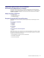
Regulatory Specifications and Disclaimers . . . . . . . . . . . . . . . . . . . . . . . . . . . . . . . . . .
Declaration of the Manufacturer or Importer . . . . . . . . . . . . . . . . . . . . . . . . . . . . . . .
Safety Compliance Statement . . . . . . . . . . . . . . . . . . . . . . . . . . . . . . . . . . . . . . . . . . .
European Community (EC) Council Directives . . . . . . . . . . . . . . . . . . . . . . . . . . . . .
Electromagnetic Compatibility . . . . . . . . . . . . . . . . . . . . . . . . . . . . . . . . . . . . . .
Low Voltage . . . . . . . . . . . . . . . . . . . . . . . . . . . . . . . . . . . . . . . . . . . . . . . . . . . . . .
EC Conformity . . . . . . . . . . . . . . . . . . . . . . . . . . . . . . . . . . . . . . . . . . . . . . . . . . .
Telecommunications Terminal Equipment . . . . . . . . . . . . . . . . . . . . . . . . . . . .
Federal Communications Commission (FCC) Statement . . . . . . . . . . . . . . . . . . . .
FCC Declaration of Conformity . . . . . . . . . . . . . . . . . . . . . . . . . . . . . . . . . . . . . . . . . .
Canadian Compliance Statement (Industry Canada) . . . . . . . . . . . . . . . . . . . . . . .
Electromagnetic Compatibility . . . . . . . . . . . . . . . . . . . . . . . . . . . . . . . . . . . . . .
Laser Compliance Notice . . . . . . . . . . . . . . . . . . . . . . . . . . . . . . . . . . . . . . . . . . . . . . .
Definition of Safety Notices . . . . . . . . . . . . . . . . . . . . . . . . . . . . . . . . . . . . . . . . . . . . . . . .
Electrical Safety . . . . . . . . . . . . . . . . . . . . . . . . . . . . . . . . . . . . . . . . . . . . . . . . . . . . . . . . .
Laser Safety Information . . . . . . . . . . . . . . . . . . . . . . . . . . . . . . . . . . . . . . . . . . . . . . . . . .
Data Integrity and Verification . . . . . . . . . . . . . . . . . . . . . . . . . . . . . . . . . . . . . . . . . . . . .
Presentation . . . . . . . . . . . . . . . . . . . . . . . . . . . . . . . . . . . . . . . . . . . . . . . . . . . . . . . . . . . .
Rack Models . . . . . . . . . . . . . . . . . . . . . . . . . . . . . . . . . . . . . . . . . . . . . . . . . . . . . . . . . .
Configuration Examples . . . . . . . . . . . . . . . . . . . . . . . . . . . . . . . . . . . . . . . . . . . . . . . .
Desktop Model . . . . . . . . . . . . . . . . . . . . . . . . . . . . . . . . . . . . . . . . . . . . . . . . . . . . . . . .
Important Safety Instructions . . . . . . . . . . . . . . . . . . . . . . . . . . . . . . . . . . . . . . . . . . . . . .
Checking Power Cords . . . . . . . . . . . . . . . . . . . . . . . . . . . . . . . . . . . . . . . . . . . . . . . . . . .
Delivery . . . . . . . . . . . . . . . . . . . . . . . . . . . . . . . . . . . . . . . . . . . . . . . . . . . . . . . . . . . . . . . .
Rack–Mounted Versions . . . . . . . . . . . . . . . . . . . . . . . . . . . . . . . . . . . . . . . . . . . . . . . .
Desktop Versions . . . . . . . . . . . . . . . . . . . . . . . . . . . . . . . . . . . . . . . . . . . . . . . . . . . . . .
Connections and Controls . . . . . . . . . . . . . . . . . . . . . . . . . . . . . . . . . . . . . . . . . . . . . . . . .
Connecting the Monitor, Keyboard, and Mouse . . . . . . . . . . . . . . . . . . . . . . . . . . . . . .
Powering On the Server for the First Time . . . . . . . . . . . . . . . . . . . . . . . . . . . . . . . . . . .
Mounting the DVD/CD–RW Drive . . . . . . . . . . . . . . . . . . . . . . . . . . . . . . . . . . . . . . . . . .
The NovaScale 4020 Server Resource CD . . . . . . . . . . . . . . . . . . . . . . . . . . . . . . . . . .
The NovaScale 4020 User’s Guide . . . . . . . . . . . . . . . . . . . . . . . . . . . . . . . . . . . . . . . . .
Handling the Black Cover on Desktop Models . . . . . . . . . . . . . . . . . . . . . . . . . . . . . . .
Removing the Black Cover . . . . . . . . . . . . . . . . . . . . . . . . . . . . . . . . . . . . . . . . . . . . . .
Installing the Black Cover . . . . . . . . . . . . . . . . . . . . . . . . . . . . . . . . . . . . . . . . . . . . . . .
AZERTY/QWERTY Keyboard Lookup Table . . . . . . . . . . . . . . . . . . . . . . . . . . . . . . . . .
NovaScale 4020 Server Cabinet Specifications . . . . . . . . . . . . . . . . . . . . . . . . . . . . . .
NovaScale 4020 Server CPU Drawer Specifications . . . . . . . . . . . . . . . . . . . . . . . . . .
Warnings . . . . . . . . . . . . . . . . . . . . . . . . . . . . . . . . . . . . . . . . . . . . . . . . . . . . . . . . . . . . . . .
WARNING: English (USA) . . . . . . . . . . . . . . . . . . . . . . . . . . . . . . . . . . . . . . . . . . . . . .
AVERTISSEMENTS : Français . . . . . . . . . . . . . . . . . . . . . . . . . . . . . . . . . . . . . . . . . .
WARNUNG: Deutsch . . . . . . . . . . . . . . . . . . . . . . . . . . . . . . . . . . . . . . . . . . . . . . . . . .
AVVERTENZA: Italiano . . . . . . . . . . . . . . . . . . . . . . . . . . . . . . . . . . . . . . . . . . . . . . . . .
ADVERTENCIA: Español . . . . . . . . . . . . . . . . . . . . . . . . . . . . . . . . . . . . . . . . . . . . . . .
NovaScale 4020 Quick Start Guide
5
5
5
5
5
5
5
5
6
6
6
6
6
7
7
8
8
9
9
10
11
12
12
14
14
14
15
17
18
19
19
19
20
20
20
22
23
25
27
27
29
31
33
35
3
4
List of Figures
Figure 1. 19” / 19U and 19” / 36U cabinets . . . . . . . . . . . . . . . . . . . . . . . . . . . . . . . . . .
Figure 2. 36U cabinet configuration (example) . . . . . . . . . . . . . . . . . . . . . . . . . . . . . . .
Figure 3. 19U cabinet configuration (example) . . . . . . . . . . . . . . . . . . . . . . . . . . . . . . .
Figure 4. NovaScale 4020 Desktop model . . . . . . . . . . . . . . . . . . . . . . . . . . . . . . . . . . .
Figure 5. NovaScale 4020 Server Front View . . . . . . . . . . . . . . . . . . . . . . . . . . . . . . . .
Figure 6. NovaScale 4020 Server Front View (shown with bezel removed) . . . . . .
Figure 7. Front Panel View . . . . . . . . . . . . . . . . . . . . . . . . . . . . . . . . . . . . . . . . . . . . . . . .
Figure 8. NovaScale 4020 Server Back Panel Features . . . . . . . . . . . . . . . . . . . . . . .
Figure 9. NovaScale 4020 desktop Black Cover . . . . . . . . . . . . . . . . . . . . . . . . . . . . . .
Figure 10. J–rails . . . . . . . . . . . . . . . . . . . . . . . . . . . . . . . . . . . . . . . . . . . . . . . . . . . . . . . .
Figure 11. AZERTY keyboard . . . . . . . . . . . . . . . . . . . . . . . . . . . . . . . . . . . . . . . . . . . . . .
Figure 12. QWERTY keyboard . . . . . . . . . . . . . . . . . . . . . . . . . . . . . . . . . . . . . . . . . . . .
9
10
10
11
15
15
16
17
20
21
22
22
List of Tables
Table 1. Front Panel Switches, Indicators and Connectors . . . . . . . . . . . . . . . . . . . . .
Table 2. Back Panel Switches, Indicators and Connectors . . . . . . . . . . . . . . . . . . . . .
Table 3. NovaScale 4020 Server cabinet specifications . . . . . . . . . . . . . . . . . . . . . . .
Table 4. NovaScale 4020 Server CPU drawer specifications . . . . . . . . . . . . . . . . . . .
16
17
24
25
NovaScale 4020 Quick Start Guide
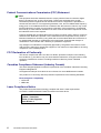
Regulatory Specifications and Disclaimers
Declaration of the Manufacturer or Importer
We hereby certify that this product is in compliance with European Union EMC Directive
89/336/EEC, using standards EN55022 (Class A) and EN55024 and Low Voltage Directive
73/23/EEC, using standard EN60950. The product has been marked with the CE Mark to
illustrate its compliance.
Safety Compliance Statement
• UL 60950 (USA)
• IEC 60950 (International)
• CSA 60950 (Canada)
European Community (EC) Council Directives
This product is in conformity with the protection requirements of the following EC Council
Directives:
Electromagnetic Compatibility
• 89/336/EEC
Low Voltage
• 73/23/EEC
EC Conformity
• 93/68/EEC
Telecommunications Terminal Equipment
• 199/5/EC
Neither the provider nor the manufacturer can accept responsibility for any failure to satisfy
the protection requirements resulting from a non-recommended modification of the product.
Compliance with these directives requires:
• an EC declaration of conformity from the manufacturer
• an EC label on the product
• technical documentation
NovaScale 4020 Quick Start Guide
5
Federal Communications Commission (FCC) Statement
Note:
This equipment has been tested and found to comply with the limits for a Class A digital
device, pursuant to Part 15 of the FCC Rules. These limits are designed to provide
reasonable protection against harmful interference when the equipment is operated in a
commercial environment. This equipment generates, uses, and can radiate radio frequency
energy and, if not installed and used in accordance with the instruction manual, may cause
harmful interference to radio communications. Operation of this equipment in a residential
area is likely to cause harmful interference in which case the user will be required to correct
the interference at his own expense.
Properly shielded and grounded cables and connectors must be used in order to meet FCC
emission limits. Neither the provider nor the manufacturer are responsible for any radio or
television interference caused by using other than recommended cables and connectors or
by unauthorized changes or modifications to this equipment. Unauthorized changes or
modifications could void the user’s authority to operate the equipment.
Any changes or modifications not expressly approved by the grantee of this device could
void the user’s authority to operate the equipment. The customer is responsible for ensuring
compliance of the modified product.
FCC Declaration of Conformity
This device complies with Part 15 of the FCC Rules. Operation is subject to the following
two conditions: (1) this device may not cause harmful interference, and (2) this device must
accept any interference received, including interference that may cause undesired
operation.
Canadian Compliance Statement (Industry Canada)
This Class A digital apparatus meets all requirements of the Canadian Interference Causing
Equipment Regulations.
Cet appareil numérique de la classe A est conforme à la norme NMB–003 du Canada.
This product is in conformity with the protection requirements of the following standards:
Electromagnetic Compatibility
• ICES–003
• NMB–003
Laser Compliance Notice
This product that uses laser technology complies with Class 1 laser requirements.
A CLASS 1 LASER PRODUCT label is located on the laser device.
Class 1 Laser Product
Luokan 1 Laserlaite
Klasse 1 Laser Apparat
Laser Klasse 1
6
NovaScale 4020 Quick Start Guide
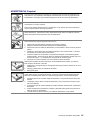
Definition of Safety Notices
DANGER
A Danger notice indicates the presence of a hazard that has the potential of causing
death or serious personal injury.
CAUTION:
A Caution notice indicates the presence of a hazard that has the potential of causing
moderate or minor personal injury.
Warning:
A Warning notice indicates an action that could cause damage to a program, device,
system, or data.
Electrical Safety
The following safety instructions shall be observed when connecting or disconnecting
devices to the system.
DANGER
The Customer is responsible for ensuring that the AC electricity supply is compliant
with national and local recommendations, regulations, standards and codes of
practice.
An incorrectly wired and grounded electrical outlet may place hazardous voltage on
metal parts of the system or the devices that attach to the system and result in an
electrical shock.
It is mandatory to remove power cables from electrical outlets before relocating the
system.
CAUTION:
This unit has more than one power supply cable. Follow procedures for removal of
power from the system when directed.
NovaScale 4020 Quick Start Guide
7
Laser Safety Information
The optical drive in this system unit is a classified as a Class 1 level Laser product. The
optical drive has a label that identifies its classification.
The optical drive in this system unit is certified in the U.S. to conform to the requirements of
the Department of Health and Human Services 21 Code of Federal Regulations (DHHS 21
CFR) Subchapter J for Class 1 laser products. Elsewhere, the drive is certified to conform to
the requirements of the International Electrotechnical Commission (IEC) 60825–1: 2001 and
CENELEC EN 60825–1: 1994 for Class 1 laser products.
CAUTION:
Invisible laser radiation when open. Do not stare into beam or view directly with
optical instruments.
Class 1 Laser products are not considered to be hazardous. The optical drive contains
internally a Class 3B gallium–arsenide laser that is nominally 30 milliwatts at 830
nanometers. The design incorporates a combination of enclosures, electronics, and
redundant interlocks such that there is no exposure to laser radiation above a Class 1 level
during normal operation, user maintenance, or servicing conditions.
Data Integrity and Verification
Warning:
Bull NovaScale Servers are designed to reduce the risk of undetected data corruption
or loss. However, if unplanned outages or system failures occur, users are strongly
advised to check the accuracy of the operations performed and the data saved or
transmitted by the system at the time of outage or failure.
8
NovaScale 4020 Quick Start Guide
Presentation
Rack Models
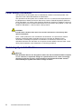
The server is delivered rack–mounted, pre–cabled and pre–configured in one 19”/19U or
19”/36U cabinet, according to the version chosen.
Figure 1.
19” / 19U and 19” / 36U cabinets
NovaScale 4020 Quick Start Guide
9
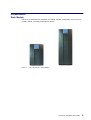
Configuration Examples
NovaScale 4020 servers
NovaScale 4040 server
Console drawer
Keyboard, Video, Mouse
8–slot SCSI RAID
disk rack drawers
KVM switch
NovaScale 4040 server
14–slot SCSI RAID
disk rack drawer
NovaScale 4040 server
Figure 2.
36U cabinet configuration (example)
KVM switch
Console drawer
Keyboard, Video, Mouse
8–slot SCSI RAID
disk rack drawers
NovaScale 4020 servers
14–slot SCSI RAID
disk rack drawer
NovaScale 4040 server
Figure 3.
10
19U cabinet configuration (example)
NovaScale 4020 Quick Start Guide
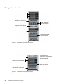
Desktop Model
Figure 4.
NovaScale 4020 Desktop model
NovaScale 4020 Quick Start Guide
11
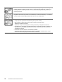
Important Safety Instructions
Before proceeding to install the server, read all caution and safety statements at the end of
this document.
CAUTION:
Electrostatic discharge (ESD) can damage disk drives, add–in cards, and other parts.
This server can withstand normal levels of environmental ESD. Wear an anti–static
wrist strap attached to chassis ground of the server (i.e. any unpainted metal surface)
when handling components.
CAUTION:
Grounded outlet:
Ensure that the power service connection is through a properly grounded outlet.
Warning:
The following instructions are to be complied with for all rack–mounted servers:
Main AC power disconnects:
You are responsible for installing an AC power disconnect for the entire cabinet.
This main disconnect must be readily accessible, and it must be labeled as
controlling power to the entire cabinet and not just to the server(s).
Grounding the cabinet:
To avoid the potential for an electrical shock hazard, you must provide three–wire
safety–grounding for the cabinet and its contents.
Overcurrent protection:
Each server is designed for an AC line voltage source with up to 20 amperes of
overcurrent protection. If the power system for the cabinet is installed on a branch
circuit with more than 20 amperes of protection, you must provide supplemental
protection for the server.
Checking Power Cords
Warning:
The Power button on the server control panel does not completely remove AC power.
To completely remove AC power from the server, you must unplug all AC power
cords from the server or from the wall outlet.
Warning:
Do not attempt to modify or use an AC power cord that is not the exact type required.
12
NovaScale 4020 Quick Start Guide
Rack–mounted servers:
1. Server power units must be connected to the PDU(s) (Power Distribution Unit(s))
located inside the cabinet. Connect server power cords to the outlets at the front
of the PDU(s). Do NOT use the outlets at the rear of the PDU(s).
2. Connect the PDU(s) to the site power supply with the power cord(s) provided with
the PDU(s).
Desktop servers:
1. U.S. / Canada:
Cords must be UL Listed/CSA Certified, 16/3, 75C type, VW–1, SJT/SVT, with NEMA
5–15P or NEMA 6–15P attachment plug and IEC 320 C13 input power connector
rated 15 amps.
Outside U.S. / Canada:
Cords must be flexible harmonized (<HAR>) rated 250V, 1.0 mm minimum
conductor size with IEC 320 C13 input power connector and rated for no less than
10 amps.
2. AC attachment connector:
The AC wall attachment plug should be a three conductor grounding type in
compliance with the national and regional standards in force :
– Nominal voltage: 125 V / 250 V
– Nominal amperage: 15 A
The AC wall attachment plug must bear an accepted safety agency certification
mark for the specific country or country.
3. Input power connector, server end:
The connectors that plug into the AC receptacles on the server must be an IEC
320, sheet C13 type female connectors :
– Nominal voltage: 125 V / 250 V
– Nominal amperage: 15 A
Note:
Surge Suppressor Recommendations:
In geographic regions that are susceptible to electrical storms, we highly recommend
that you plug the server into a surge suppressor.
EMI Information:
For information about complying with electromagnetic interference regulations, see
“Electromagnetic Compatibility” in the NovaScale User’s Guide.
Desktop servers:
Note:
Identification Label: On Desktop servers, the identification label sticked under the
bottom of the server summarizes these requirements and provides regulatory
information.
NovaScale 4020 Quick Start Guide
13
Delivery
Rack–Mounted Versions
Site preparation must be completed by the pre–arranged delivery date. Any delay due to
non–completion of the site by the pre–arranged date will be considered as the Customer’s
responsibility. See the NovaScale Series Site Preparation Guide.
The server is delivered 24 hours in advance of the scheduled installation date. On arrival,
the server must be placed, in its packing, in the Computer Room so that it reaches room
temperature before powering up (optimum operating temperature = 22° C + 3° C,
hygrometry = 50% + 5%).
CAUTION:
It is mandatory for the server to be transported vertically. The server cabinet is
extremely heavy and requires the use of an elevator. The Data Processing Site
manager must allocate enough personnel to ensure safe handling.
Desktop Versions
The server operates reliably within normal office environmental limits. Select a site that
meets the following criteria:
• Near a properly earthed, grounded three–pronged power outlet:
– In the United States and Canada: a NEMA–compliant, 110–208 V∼ outlet rated for
15 amps.
– In other geographic areas: a properly grounded, earthed outlet in accordance with the
local electrical authorities and electrical code of the region.
• Clean and relatively free of excess dust.
• Well ventilated and away from sources of heat, with the ventilating openings on the
server kept free of obstructions.
• Away from sources of vibration or physical shock.
• Isolated from strong electromagnetic fields and noise caused by electrical devices such
as elevators, copy machines, air conditioners, large fans, large electric motors, radio and
TV transmitters, and high–frequency security devices.
CAUTION:
The maximum server configuration weighs approximately 65 lbs (30 kg).
To avoid personal injury when unpacking the server, use only a mechanical assist
unit to lift it off the shipping pallet.
Two people are required to lift the server.
Do not attempt to lift or move the server by the handles on the power supplies.
If you need to move the server from one location to another, use a hand–truck or
other mechanical assist unit.
14
NovaScale 4020 Quick Start Guide
Connections and Controls
Figures 5 and 6 show the NovaScale 4020 Server and peripheral bay module.
Figure 5.
NovaScale 4020 Server Front View
Hard Drives
Power Bay
Figure 6.
DVD/CD Drive
Front Panel
Power Supply Modules
NovaScale 4020 Server Front View (shown with bezel removed)
NovaScale 4020 Quick Start Guide
15
Figure 7 shows front control panel switches, indicators and connectors.
View with Front Bezel Removed
View with Front Bezel Installed
Figure 7.
Front Panel View
Feature
Description
Item
Front Panel Switches and LED Indicators
A
System Power switch
Toggles system power.
and LED
LED
State
ACPI
Off
Power off
No
On
Power on
No
Off
S4 / S5
Yes
On
S0
Yes
B
System Reset switch
Resets the system.
C
SDINT (System Diagnostic
Asserts SDINT.
Interrupt) switch
D
System ID switch and LED (Blue)
System identification switch and light
E
System Status/Fault LED (Green/ Indicates system status.
Amber)
LED
State
Description
Off
Not ready
Post err/NMI Ev/CPU missing
Green,
Ready
No Alarms
On
Green,
Ready – Degraded CPU Fault, DIMM killed
Blinking
Amber,
Critical Alarm
Critical of Pwr Flt, Fan, Voltage,
On
and Temperature failures.
Amber,
Non–Critical Alarm Non–Critical of redundant Pwr
Blinking
Flt, redundant Fan, Voltage, and
Temperature failures.
F
Hard Drive Fault LED (Amber)
Indicates Hard drive subsystem fault status.
LED
State
Description
Off
Drive Missing
Slot Empty, Online, Prepare for
removal.
On
Inactive
Drive Failed
Blinking
Drive Identity, Rebuild, Predictive Fail, Rebuild Interrupt or
Rebuild on empty slot.
G, H
LAN1, LAN2 Status LEDs (Green) Indicates LAN activity status.
LED
State
Description
Off
Inactive
No Connection or Link
On
Idle
Link and No Activity
Blinking
Active
Access / Activity
Front Panel Connectors
I
Video connector
Video port, standard VGA compatible, 15–pin connector
J
USB3 connector
USB port 3, 4–pin connector
K
USB4 connector
USB port 4, 4–pin connector
Table 1.
16
Front Panel Switches, Indicators and Connectors
NovaScale 4020 Quick Start Guide
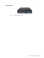
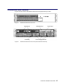
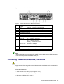
Figure 8 shows back panel switches, indicators and connectors.
Figure 8.
Item
A
B
C
D
E
F
G
H
I
Table 2.
NovaScale 4020 Server Back Panel Features
Description
PCI Slots
Slot 1
100 MHz, 64–bit PCI–X slot, full length
Slot 2
100 MHz, 64–bit PCI–X slot, full length
Slot 3
133 MHz, 64–bit PCI–X slot, full length
Two AC input power connectors
External SCSI connector1
System ID switch
System ID LED (blue)
Two LAN ports, RJ45 connector (LAN1 on bottom, LAN2 on top)
LAN port LEDs:
Green LED
On – ethernet link is detected
Off – no ethernet connection
Blinking – ethernet link is active
Green/Amber
Ethernet speed indicator
dual color LED
Green On – 100 Mbps
Amber On – 1000 Mbps
Serial port2, RJ45 connector
Two USB 1.1 ports, 4–pin connectors (USB0 on bottom, USB1 on top)
Video port, standard VGA compatible, 15–pin connector
Back Panel Switches, Indicators and Connectors
Note:
1. External SCSI bus supports both LVDS and SE signals via the external SCSI connector.
2. EMP access is provided via shared serial port.
Connecting the Monitor, Keyboard, and Mouse
CAUTION:
Unplug server before connecting external devices, make sure the server is not plugged in or
equipment could be damaged.
Before powering on the server, you must connect these devices to the back of the
NovaScale 4020 Server.
1. Video monitor to the video port (I in Figure 7. or 8 )
2. Keyboard to a USB port (G in Figure 7. )
3. Mouse to a USB port (G in Figure 7. )
NovaScale 4020 Quick Start Guide
17
Powering On the Server for the First Time
The first time you power on the server, you need to enter the BIOS Setup Utility and set the
correct date and time values. The server then executes its Power–On Self Test (POST)
sequence and passes control to the Boot Manager. From the Boot Manager, you can mount
the DVD/CD–RW device to block zero and then load the operating system.
For further information about the Boot Manager, the EFI Shell, and the BIOS Setup Utility,
refer to the NovaScale 4020 User’s Guide.
Warning:
The EFI shell can only manage QWERTY keyboards. If you have an AZERTY
keyboard, please refer to the AZERTY/QWERTY keyboard lookup table on page 22.
Follow these steps to power up the NovaScale 4020 Server for the first time:
1. Ensure that all external devices are connected (monitor, keyboard, mouse, disk racks,
printers, etc).
2. Plug the female ends of both AC power cords into the back of the chassis (B 1 and 2 in
Figure 8)
3. Plug the male ends of the server AC power cords into outlets at the front of the Power
Distribution Unit when rack–mounted or into wall outlets otherwise.
4. Power on the video monitor.
5. Press the Power button on the front control panel (A in Figure 7. Front Panel View). The
server fans start up and POST begins.
6. When POST displays the message:
“Hit <F2> if you want to run SETUP,”
enter <F2>. The system will enter the BIOS Setup Utility.
If you see a prompt asking for a system password, press the <ENTER> key for direct
access to the BIOS Setup Utility.
7. From the BIOS Setup Utility Main menu, use the arrow keys to move the cursor down to
system date and time selections. Position the cursor over the date and time values and
enter appropriate values. Use the <tab> key to move within the date and time fields.
8. Use the arrow key to access the Exit menu and select Save changes and exit the
BIOS Setup Utility. After you exit the utility, the boot procedure resumes. You can
monitor the remainder of the boot progress on the video display.
Note:
POST checks the processors, memory, keyboard, and most installed peripheral devices.
During the memory test, POST displays the amount of memory it is able to access and test.
The length of time needed to test memory depends on the amount of memory installed.
POST is stored in flash memory.
9. The AMI* BIOS banner displays the loaded versions of the BIOS, PAL, SAL, and EFI.
10.The LSI* banner appears and indicates the recognized drives. Note that a Platform
Configuration EFI based configuration utility is required to enter the LSI SCSI utility. The
LSI* SCSI utility enables you to manage and configure the server’s SCSI devices.
11. POST concludes and passes control to the Boot Manager.
18
NovaScale 4020 Quick Start Guide
12.From the Boot Manager, you can use the arrow keys to highlight and select the option
that invokes the EFI Shell or the Boot Maintenance Menu. Booting to the EFI Shell
causes the following prompt to appear:
Shell>
13.Mount the DVD/CD–RW device as block zero. See “Mounting the DVD/CD–RW Device”
below.
14.Boot the operating system that you want to run on the server.
Mounting the DVD/CD–RW Drive
You must mount the DVD–CD–RW drive before you can use it to read media:
1. Ensure that you are in the EFI Shell. You should see the following prompt:
Shell>
2. For the mount command in the next step to work, the drive must be loaded with media.
3. At the shell prompt, enter the following command:
mount –r
The media in the DVD/CD–RW drive is mapped to one of the file systems, i.e., FS0:, FS1:,
FS2. Change to the appropriate file system and enter the following command:
ls
The NovaScale 4020 Server Resource CD
The NovaScale 4020 Resource CD has the following contents: System Maintenance Utility
(SMU), EFI* Platform Diagnostics, the NovaScale 4020 Quick Start Guide (this guide), the
NovaScale 4020 User’s Guide and Adobe Acrobat* Reader.
The Resource CD comes with a menu driven program that can be used for the following:
1. Create a CD containing drivers for various operating systems.
2. Create a CD containing utilities, service partition and diagnostics.
3. Install EFI* Service Partition. The EFI service partition supports remote access to the
NovaScale 4020 Server, via modem or LAN, for the purpose of executing
configuration/setup utilities and diagnostics.
4. Run EFI–based utilities.
How to invoke the Resource CD menu.
1. Insert the Resource CD into the DVD/CD–RW drive before booting to EFI Shell.
2. Boot the system into EFI Shell; the EFI CD Menu program will launch automatically. If
the EFI CD Menu program does not launch in the EFI Shell, mount and map to the CD
drive, type ‘startup’ and press <Enter> to launch the EFI CD Menu.
3. Arrow key over to the Utilities and select the utility you want to run.
The NovaScale 4020 User’s Guide
The NovaScale 4020 User’s Guide comes as a single .PDF file shipped on the Resource
CD. You can use Adobe* Acrobat* Reader to view the guide.
NovaScale 4020 Quick Start Guide
19
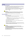
Handling the Black Cover on Desktop Models
On desktop models the server is equipped with a black cover. Figure 9 shows the black
cover removed.
Front
Rear
Figure 9.
NovaScale 4020 desktop Black Cover
Before accessing inside the server, for example to add PCI boards, this black cover must be
removed.
Removing the Black Cover
To remove the black cover, follow these instructions:
1. Remove the front bezel from the server
2. Using a screwdriver, remove the 6 screws located on the sides of the black cover (3 on
each side).
3. Push the black cover back towards the back of the system, approximately 1 centimetre
towards the rear.
4. Lift the black cover, first at the rear, then at the front; and remove it.
CAUTION:
The black cover is somewhat heavy (8 kgs)
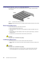
Installing the Black Cover
To install the black cover on the server chassis, follow these instructions:
1. Hold the black cover at the front and at the rear and position it above the chassis of the
server.
CAUTION:
The black cover is somewhat heavy (8 kgs)
2. Carefully lower the black cover, first at the front, in order that both sides of the black
cover position against the J–rails (see figure 2) located on each side of the server.
20
NovaScale 4020 Quick Start Guide
Figure 10.
J–rails
The front of the black cover must be about 1 centimetre back from the front of the server in
order that the 6 pins on the sides of the black cover insert inside the corresponding notches
located on the J–rails
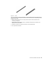
3. After the front of the black cover is fully lowered, lower the rear of the black cover,
finishing by snapping it.
4. Slide the black cover forward by about 1 centimetre until the front of the black cover
aligns the front of the server
5. Install the 6 screws on the sides of the black cover and tighten them.
6. Put in place the front bezel.
NovaScale 4020 Quick Start Guide
21
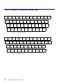
AZERTY/QWERTY Keyboard Lookup Table
1
2
3
&
é
~ ”
A
Z
Q
E
S
>
# ’
R
D
6
7
8
9
0
°
+
{ (
[ –
| è
‘ _
\ ç
^ à
@ )
] =
T
F
X
W
5
4
Y
G
C
U
H
V
I
J
B
K
N
<
Figure 11.
O
P
L
¨
£
^
$
M
¤
%
µ
ù
*
?
.
/
§
,
;
:
!
AZERTY keyboard
~
!
@
#
$
%
^
&
*
(
)
_
+
‘
1
2
3
4
5
6
7
8
9
0
–
=
Q
W
A
E
S
Z
R
D
X
Figure 12.
22
}
T
F
Y
G
C
V
U
H
B
QWERTY keyboard
NovaScale 4020 Quick Start Guide
I
J
O
K
N
M
P
L
{
}
|
[
]
\
:
”
;
’
<
>
?
,
.
/
NovaScale 4020 Server Cabinet Specifications
Rack–mounted NovaScale 4020 servers are delivered in a 19U or 36 U cabinet.
Note:
A Desktop version of the NovaScale 4020 Server is also available.
36U Cabinet Dimensions / Weight
Unpacked
Packed
Height: 174.0 cm (68.5 in)
Height: 200.5 cm (80.7 in)
Width: 65.0 cm (25.6 in)
Depth: 113.6 cm (44.7 in)
Weight (empty): 225 kg (496 lb)
Weight (full): 680 kg (1280 lb)
Width: 80.0 cm (31.5 in)
Depth: 120.0 cm (47.2 in)
Weight (empty): 255 kg (562 lb)
Weight (full): 610 kg (1345 lb)
19U Cabinet Dimensions / Weight
Unpacked
Packed
Height: 100.0 cm (39.4 in)
Height: 118.0 cm (46.49 in)
Width: 65.0 cm (25.6 in)
Depth: 113.6 cm (44.7 in)
Weight (empty): 200 kg (440 lb)
Weight (full): 390 kg (860 lb)
Width: 80.0 cm (31.5 in)
Depth: 120.0 cm (47.2 in)
Weight (empty): 230 kg (507 lb)
Weight (full): 420 kg (927 lb)
Service Clearance
Front
Rear
Side (left and right)
150 cm
100 cm
100 cm
Power Cables
AC (20A)
Cable type
Connector type
1 per PDU
3 x 4mm / AWG # 12 (US)
C22 Appliance Coupler
It is mandatory for power lines and terminal boxes to be located within the immediate vicinity of the system and to be easily accessible. Each power line must be
connected to a separate, independent electrical panel and bipolar circuit breaker.
The PDU requires an extra cable length of 1.5 meters for connection inside the cabinet.
NovaScale 4020 Quick Start Guide
23
Electrical Specifications
(power supplies are auto–sensing and auto–ranging)
Current draw
Power consumption
Thermal dissipation
24 A max. at 240 VAC input per PDU
8800 VA (max. 36U cabinet)
5500 VA (max. 19U cabinet)
5700 VA (max. per PDU)
1500 VA / 5100 BTU (per NovaScale 4040 CPU drawer)
650 VA / 2300 BTU (per NovaScale 4020 CPU drawer)
Europe
Nominal voltage
Voltage range
Frequency
230 VAC (Phase / Neutral)
207 – 244 VAC
50 Hz 1%
United States of America
Nominal voltage
Voltage range
Frequency
208 VAC (Phase / Neutral)
182 – 229 VAC
60 Hz 0.3%
Japan
Nominal voltage
Voltage range
Frequency
200 VAC (Phase / Neutral)
188 – 212 VAC
60 Hz 0.2%
Brazil
Nominal voltage
Voltage range
Frequency
220 VAC (Phase / Neutral)
212 – 231 VAC
60 Hz 2%
Breaker Protection
Mains power PDU
Maximum inrush current
Table 3.
24
20A Curve C
210A / per quarter period
NovaScale 4020 Server cabinet specifications
NovaScale 4020 Quick Start Guide
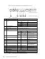
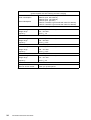
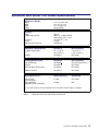
NovaScale 4020 Server CPU Drawer Specifications
Dimensions / Weight
Height
Width
Depth
Weight
Electrical
Power
Voltage range (V ac)
Frequency
current
Thermal output (typical)
Temperature Requirements
Dry Bulb Temperature
8.77 cm (3.5 in, 2U)
44.9 cm (17.7 in)
74.7 cm (29.4 in)
30 kg (65 lbs)
650 VA
200 V ac to 240 nominal,
autoranging +6%, –10%
50 to 60 Hz 5%
3 amps
2300 Btu/hr
Gradient
Operating
10 to 35C
(50 to 95F)
Not stated
Non–Operating
–40 to 70C
(–40 to 158F)
Not stated
Humidity Requirements
(noncondensing)
Gradient
Operating
Not stated
Not stated
Non–Operating
95% RH at 25 to 30°C
Not stated
Max. Wet Bulb Temperature
Not stated
Not stated
Moisture Content
Not stated
Not stated
Noise Emissions (1)
System Running
System Idle
Sound Power
(Dome method)
Sound Pressure
(Bystander, Floor–standing)
6.7 BA
Not stated
55 dBA
N/A
(1) Acoustic tests at room temperature of 28°C (82°F) without failure condition.
Table 4.
NovaScale 4020 Server CPU drawer specifications
NovaScale 4020 Quick Start Guide
25
26
NovaScale 4020 Quick Start Guide
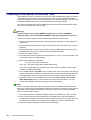
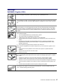
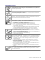
Warnings
WARNING: English (USA)
The power supply in this product contains no user–serviceable parts. There may be more
than one supply in this product. Refer servicing only to qualified personnel.
Do not attempt to modify or use the supplied AC power cord if it is not the exact type required.
A product with more than one power supply will have a separate AC power cord for each supply.
The power button on the system does not turn off system AC power. To remove AC power
from the system, you must unplug each AC power cord from the wall outlet or power supply.
The power cord(s) is considered the disconnect device to the main (AC) power. The socket
outlet that the system plugs into shall be installed near the equipment and shall be easily accessible.
SAFETY STEPS: Whenever you remove the chassis covers to access the inside of the system, follow these steps:
1.
2.
3.
4.
5.
6.
Turn off all peripheral devices connected to the system.
Turn off the system by pressing the power button.
Unplug all AC power cords from the system or from wall outlets.
Label and disconnect all cables connected to I/O connectors or ports on the back of the
system.
Provide some electrostatic discharge (ESD) protection by wearing an antistatic wrist
strap attached to chassis ground of the system—any unpainted metal surface—when
handling components.
Do not operate the system with the chassis covers removed.
After you have completed the six SAFETY steps above, you can remove the system covers.
To do this:
1.
2.
3.
Unlock and remove the padlock from the back of the system if a padlock has been
installed.
Remove and save all screws from the covers.
Remove the covers.
For proper cooling and airflow, always reinstall the chassis covers before turning on the system. Operating the system without the covers in place can damage system parts. To install
the covers:
1.
2.
3.
4.
5.
Check first to make sure you have not left loose tools or parts inside the system.
Check that cables, add–in boards, and other components are properly installed.
Attach the covers to the chassis with the screws removed earlier, and tighten them firmly.
Insert and lock the padlock to the system to prevent unauthorized access inside the system.
Connect all external cables and the AC power cord(s) to the system.
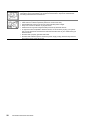
A microprocessor and heat sink may be hot if the system has been running. Also, there may
be sharp pins and edges on some board and chassis parts. Contact should be made with
care. Consider wearing protective gloves.
NovaScale 4020 Quick Start Guide
27
Danger of explosion if the battery is incorrectly replaced. Replace only with the same or
equivalent type recommended by the equipment manufacturer. Dispose of used batteries
according to manufacturer’s instructions.
The system is designed to operate in a typical office environment. Choose a site that is:
•
•
•
•
•
Clean and free of airborne particles (other than normal room dust).
Well ventilated and away from sources of heat including direct sunlight.
Away from sources of vibration or physical shock.
Isolated from strong electromagnetic fields produced by electrical devices.
In regions that are susceptible to electrical storms, we recommend you plug your system
into a surge suppresser and disconnect telecommunication lines to your modem during an
electrical storm.
• Provided with a properly grounded wall outlet.
• Provided with sufficient space to access the power supply cord(s), because they serve as
the product’s main power disconnect.
28
NovaScale 4020 Quick Start Guide
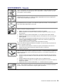
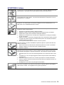
AVERTISSEMENTS : Français
Le bloc d’alimentation de ce produit ne contient aucune pièce pouvant être réparée par l’utilisateur. Ce produit peut contenir plus d’un bloc d’alimentation. Veuillez contacter un technicien qualifié en cas de problème.
Ne pas essayer d’utiliser ni modifier le câble d’alimentation CA fourni, s’il ne correspond pas
exactement au type requis. Le nombre de câbles d’alimentation CA fournis correspond au
nombre de blocs d’alimentation du produit.
Notez que le commutateur CC de mise sous tension /hors tension du panneau avant n’éteint
pas l’alimentation CA du système. Pour mettre le système hors tension, vous devez débrancher chaque câble d’alimentation de sa prise.
CONSIGNES DE SÉCURITÉ –Lorsque vous ouvrez le boîtier pour accéder à l’intérieur du
système, suivez les consignes suivantes:
1.
2.
3.
4.
5.
6.
Mettez hors tension tous les périphériques connectés au système.
Mettez le système hors tension en mettant l’interrupteur général en position OFF (bouton–poussoir).
Débranchez tous les cordons d’alimentation c.a. du système et des prises murales.
Identifiez et débranchez tous les câbles reliés aux connecteurs d’E–S ou aux accès derrière le système.
Pour prévenir les décharges électrostatiques lorsque vous touchez aux composants,
portez une bande antistatique pour poignet et reliez–la à la masse du système (toute
surface métallique non peinte du boîtier).
Ne faites pas fonctionner le système tandis que le boîtier est ouvert.
Une fois TOUTES les étapes précédentes accomplies, vous pouvez retirer les panneaux du
système. Procédez comme suit:
1.
2.
3.
Si un cadenas a été installé sur à l’arrière du système, déverrouillez–le et retirez–le.
Retirez toutes les vis des panneaux et mettez–les dans un endroit sûr.
Retirez les panneaux.
Afin de permettre le refroidissement et l’aération du système, réinstallez toujours les panneaux du boîtier avant de mettre le système sous tension. Le fonctionnement du système en
l’absence des panneaux risque d’endommager ses pièces. Pour installer les panneaux, procédez comme suit:
1.
2.
3.
4.
5.
Assurez–vous de ne pas avoir oublié d’outils ou de pièces démontées dans le système.
Assurez–vous que les câbles, les cartes d’extension et les autres composants sont bien
installés.
Revissez solidement les panneaux du boîtier avec les vis retirées plus tôt.
Remettez le cadenas en place et verrouillez–le afin de prévenir tout accès non autorisé à
l’intérieur du système.
Rebranchez tous les cordons d’alimentation c. a. et câbles externes au système.
Le microprocesseur et le dissipateur de chaleur peuvent être chauds si le système a été sous
tension. Faites également attention aux broches aiguës des cartes et aux bords tranchants
du capot. Nous vous recommandons l’usage de gants de protection.
NovaScale 4020 Quick Start Guide
29
Danger d’explosion si la batterie n’est pas remontée correctement. Remplacer uniquement
avec une batterie du même type ou d’un type équivalent recommandé par le fabricant. Disposez des piles usées selon les instructions du fabricant.
Le système a été conçu pour fonctionner dans un cadre de travail normal. L’emplacement
choisi doit être:
•
•
•
•
•
Propre et dépourvu de poussière en suspension (sauf la poussière normale).
Bien aéré et loin des sources de chaleur, y compris du soleil direct.
A l’abri des chocs et des sources de vibrations.
Isolé de forts champs électromagnétiques géenérés par des appareils électriques.
Dans les régions sujettes aux orages magnétiques il est recomandé de brancher votre système à un supresseur de surtension, et de débrancher toutes les lignes de télécommunications de votre modem durant un orage.
• Muni d’une prise murale correctement mise à la terre.
• Suffisamment spacieux pour vous permettre d’accéder aux câbles d’alimentation (ceux–ci
étant le seul moyen de mettre le système hors tension).
30
NovaScale 4020 Quick Start Guide
WARNUNG: Deutsch
Benutzer können am Netzgerät dieses Produkts keine Reparaturen vornehmen. Das Produkt
enthält möglicherweise mehrere Netzgeräte. Wartungsarbeiten müssen von qualifizierten
Technikern ausgeführt werden.
Versuchen Sie nicht, das mitgelieferte Netzkabel zu ändern oder zu verwenden, wenn es sich
nicht genau um den erforderlichen Typ handelt. Ein Produkt mit mehreren Netzgeräten hat
für jedes Netzgerät ein eigenes Netzkabel.
Der Wechselstrom des Systems wird durch den Ein–/Aus–Schalter für Gleichstrom nicht ausgeschaltet. Ziehen Sie jedes Wechselstrom–Netzkabel aus der Steckdose bzw. dem Netzgerät, um den Stromanschluß des Systems zu unterbrechen.
SICHERHEISMASSNAHMEN: Immer wenn Sie die Gehäuseabdeckung abnehmen um an
das Systeminnere zu gelangen, sollten Sie folgende Schritte beachten:
1.
2.
3.
4.
5.
6.
Schalten Sie alle an Ihr System angeschlossenen Peripheriegeräte aus.
Schalten Sie das System mit dem Hauptschalter aus.
Ziehen Sie den Stromanschlußstecker Ihres Systems aus der Steckdose.
Auf der Rückseite des Systems beschriften und ziehen Sie alle Anschlußkabel von den
I/O Anschlüssen oder Ports ab.
Tragen Sie ein geerdetes Antistatik Gelenkband, um elektrostatische Ladungen (ESD)
über blanke Metallstellen bei der Handhabung der Komponenten zu vermeiden.
Schalten Sie das System niemals ohne ordnungsgemäß montiertes Gehäuse ein.
Nachdem Sie die oben erwähnten ersten sechs SICHERHEITSSCHRITTE durchgeführt haben, können Sie die Abdeckung abnehmen, indem Sie:
1.
2.
3.
Öffnen und entfernen Sie die Verschlußeinrichtung (Padlock) auf der Rückseite des Systems, falls eine Verschlußeinrichtung installiert ist.
Entfernen Sie alle Schrauben der Gehäuseabdeckung.
Nehmen Sie die Abdeckung ab.
Zur ordnungsgemäßen Kühlung und Lüftung muß die Gehäuseabdeckung immer wieder vor
dem Einschalten installiert werden. Ein Betrieb des Systems ohne angebrachte Abdeckung
kann Ihrem System oder Teile darin beschädigen. Um die Abdeckung wieder anzubringen:
1.
2.
3.
4.
5.
Vergewissern Sie sich, daß Sie keine Werkzeuge oder Teile im Innern des Systems
zurückgelassen haben.
Überprüfen Sie alle Kabel, Zusatzkarten und andere Komponenten auf ordnungsgemäßen Sitz und Installation.
Bringen Sie die Abdeckungen wieder am Gehäuse an, indem Sie die zuvor gelösten
Schrauben wieder anbringen. Ziehen Sie diese gut an.
Bringen Sie die Verschlußeinrichtung (Padlock) wieder an und schließen Sie diese, um
ein unerlaubtes Öffnen des Systems zu verhindern.
Schließen Sie alle externen Kabel und den AC Stromanschlußstecker Ihres Systems
wieder an.
Der Mikroprozessor und der Kühler sind möglicherweise erhitzt, wenn das System in Betrieb
ist. Außerdem können einige Platinen und Gehäuseteile scharfe Spitzen und Kanten aufweisen. Arbeiten an Platinen und Gehäuse sollten vorsichtig ausgeführt werden. Sie sollten
Schutzhandschuhe tragen.
NovaScale 4020 Quick Start Guide
31
Bei falschem Einsetzen einer neuen Batterie besteht Explosionsgefahr. Die Batterie darf nur
durch denselben oder einen entsprechenden, vom Hersteller empfohlenen Batterietyp ersetzt
werden. Entsorgen Sie verbrauchte Batterien den Anweisungen des Herstellers entsprechend.
Das System wurde für den Betrieb in einer normalen Büroumgebung entwickelt. Der Standort
sollte:
• sauber und staubfrei sein (Hausstaub ausgenommen);
• gut gelüftet und keinen Heizquellen ausgesetzt sein (einschließlich direkter Sonneneinstrahlung);
• keinen Erschütterungen ausgesetzt sein;
• keine starken, von elektrischen Geräten erzeugten elektromagnetischen Felder aufweisen;
• in Regionen, in denen elektrische Stürme auftreten, mit einem Überspannungsschutzgerät
verbunden sein; während eines elektrischen Sturms sollte keine Verbindung der Telekommunikationsleitungen mit dem Modem bestehen;
• mit einer geerdeten Wechselstromsteckdose ausgerüstet sein;
• über ausreichend Platz verfügen, um Zugang zu den Netzkabeln zu gewährleisten, da der
Stromanschluß des Produkts hauptsächlich über die Kabel unterbrochen wird.
32
NovaScale 4020 Quick Start Guide
AVVERTENZA: Italiano
Rivolgersi ad un tecnico specializzato per la riparazione dei componenti dell’alimentazione di
questo prodotto. È possibile che il prodotto disponga di più fonti di alimentazione.
Non modificare o utilizzare il cavo di alimentazione in c.a. fornito dal produttore, se non corrisponde esattamente al tipo richiesto. Ad ogni fonte di alimentazione corrisponde un cavo di
alimentazione in c.a. separato.
L’interruttore attivato/disattivato nel pannello anteriore non interrompe l’alimentazione in c.a.
del sistema. Per interromperla, è necessario scollegare tutti i cavi di alimentazione in c.a.
dalle prese a muro o dall’alimentazione di corrente.
PASSI DI SICUREZZA: Qualora si rimuovano le coperture del telaio per accedere all’interno
del sistema, seguire i seguenti passi:
1.
2.
3.
4.
5.
6.
Spegnere tutti i dispositivi periferici collegati al sistema.
Spegnere il sistema, usando il pulsante spento/acceso dell’interruttore del sistema.
Togliere tutte le spine dei cavi del sistema dalle prese elettriche.
Identificare e sconnettere tutti i cavi attaccati ai collegamenti I/O od alle prese installate
sul retro del sistema.
Qualora si tocchino i componenti, proteggersi dallo scarico elettrostatico (SES), portando
un cinghia anti–statica da polso che è attaccata alla presa a terra del telaio del sistema –
qualsiasi superficie non dipinta – .
Non far operare il sistema quando il telaio è senza le coperture.
Dopo aver seguito i sei passi di SICUREZZA sopracitati, togliere le coperture del telaio del
sistema come seque:
1.
2.
3.
Aprire e rimuovere il lucchetto dal retro del sistema qualora ve ne fosse uno installato.
Togliere e mettere in un posto sicuro tutte le viti delle coperture.
Togliere le coperture.
Per il giusto flusso dell’aria e raffreddamento del sistema, rimettere sempre le coperture del
telaio prima di riaccendere il sistema. Operare il sistema senza le coperture al loro proprio
posto potrebbe danneggiare i componenti del sistema. Per rimettere le coperture del telaio:
1.
2.
3.
4.
5.
Controllare prima che non si siano lasciati degli attrezzi o dei componenti dentro il sistema.
Controllare che i cavi, dei supporti aggiuntivi ed altri componenti siano stati installati appropriatamente.
Attaccare le coperture al telaio con le viti tolte in precedenza e avvitarle strettamente.
Inserire e chiudere a chiave il lucchetto sul retro del sistema per impedire l’accesso non
autorizzato al sistema.
Ricollegare tutti i cavi esterni e le prolunghe AC del sistema.
Se il sistema è stato a lungo in funzione, il microprocessore e il dissipatore di calore potrebbero essere surriscaldati. Fare attenzione alla presenza di piedini appuntiti e parti taglienti
sulle schede e sul telaio. È consigliabile l’uso di guanti di protezione.
NovaScale 4020 Quick Start Guide
33
Esiste il pericolo di un esplosione se la pila non viene sostituita in modo corretto. Utilizzare
solo pile uguali o di tipo equivalente a quelle consigliate dal produttore. Per disfarsi delle pile
usate, seguire le istruzioni del produttore.
Il sistema è progettato per funzionare in un ambiente di lavoro tipo. Scegliere una postazione
che sia:
• Pulita e libera da particelle in sospensione (a parte la normale polvere presente nell’ambiente).
• Ben ventilata e lontana da fonti di calore, compresa la luce solare diretta.
• Al riparo da urti e lontana da fonti di vibrazione.
• Isolata dai forti campi magnetici prodotti da dispositivi elettrici.
• In aree soggette a temporali, è consigliabile collegare il sistema ad un limitatore di corrente. In caso di temporali, scollegare le linee di comunicazione dal modem.
• Dotata di una presa a muro correttamente installata.
• Dotata di spazio sufficiente ad accedere ai cavi di alimentazione, i quali rappresentano il
mezzo principale di scollegamento del sistema.
34
NovaScale 4020 Quick Start Guide
ADVERTENCIA: Español
El usuario debe abstenerse de manipular los componentes de la fuente de alimentación de
este producto, cuya reparación debe dejarse exclusivamente en manos de personal técnico
especializado. Puede que este producto disponga de más de una fuente de alimentación.
No intente modificar ni usar el cable de alimentación de corriente alterna, si no corresponde
exactamente con el tipo requerido.
El número de cables suministrados se corresponden con el número de fuentes de alimentación de corriente alterna que tenga el producto.
Nótese que el interruptor activado/desactivado en el panel frontal no desconecta la corriente
alterna del sistema. Para desconectarla, deberá desenchufar todos los cables de corriente
alterna de la pared o desconectar la fuente de alimentación.
INSTRUCCIONES DE SEGURIDAD: Cuando extraiga la tapa del chasis para acceder al
interior del sistema, siga las siguientes instrucciones:
1.
2.
3.
4.
5.
6.
Apague todos los dispositivos periféricos conectados al sistema.
Apague el sistema presionando el interruptor encendido/apagado.
Desconecte todos los cables de alimentación CA del sistema o de las tomas de corriente
alterna.
Identifique y desconecte todos los cables enchufados a los conectores E/S o a los puertos situados en la parte posterior del sistema.
Cuando manipule los componentes, es importante protegerse contra la descarga electrostática (ESD). Puede hacerlo si utiliza una muñequera antiestática sujetada a la toma
de tierra del chasis — o a cualquier tipo de superficie de metal sin pintar.
No ponga en marcha el sistema si se han extraído las tapas del chasis.
Después de completar las seis instrucciones de SEGURIDAD mencionadas, ya puede extraer las tapas del sistema. Para ello:
1.
2.
3.
Desbloquee y extraiga el bloqueo de seguridad de la parte posterior del sistema, si se ha
instalado uno.
Extraiga y guarde todos los tornillos de las tapas.
Extraiga las tapas.
Para obtener un enfriamiento y un flujo de aire adecuados, reinstale siempre las tapas del
chasis antes de poner en marcha el sistema. Si pone en funcionamiento el sistema sin las
tapas bien colocadas puede dañar los componentes del sistema. Para instalar las tapas:
1.
2.
3.
4.
5.
Asegúrese primero de no haber dejado herramientas o componentes sueltos dentro del
sistema.
Compruebe que los cables, las placas adicionales y otros componentes se hayan instalado correctamente.
Incorpore las tapas al chasis mediante los tornillos extraídos anteriormente, tensándolos
firmemente.
Inserte el bloqueo de seguridad en el sistema y bloquéelo para impedir que pueda accederse al mismo sin autorización.
Conecte todos los cables externos y los cables de alimentación CA al sistema.
NovaScale 4020 Quick Start Guide
35
Si el sistema ha estado en funcionamiento, el microprocesador y el disipador de calor pueden
estar aún calientes. También conviene tener en cuenta que en el chasis o en el tablero puede haber piezas cortantes o punzantes. Por ello, se recomienda precaución y el uso de
guantes protectores.
Existe peligro de explosión si la pila no se cambia de forma adecuada. Utilice solamente pilas iguales o del mismo tipo que las recomendadas por el fabricante del equipo. Para deshacerse de las pilas usadas, siga igualmente las instrucciones del fabricante.
El sistema está diseñado para funcionar en un entorno de trabajo normal. Escoja un lugar:
•
•
•
•
•
Limpio y libre de partículas en suspensión (salvo el polvo normal).
Bien ventilado y alejado de fuentes de calor, incluida la luz solar directa.
Alejado de fuentes de vibración.
Aislado de campos electromagnéticos fuertes producidos por dispositivos eléctricos.
En regiones con frecuentes tormentas eléctricas, se recomienda conectar su sistema a un
eliminador de sobrevoltage y desconectar el módem de las líneas de telecomunicación
durante las tormentas.
• Provisto de una toma de tierra correctamente instalada.
• Provisto de espacio suficiente como para acceder a los cables de alimentación, ya que
éstos hacen de medio principal de desconexión del sistema.
36
NovaScale 4020 Quick Start Guide
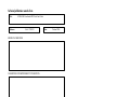
Technical publication remarks form
Title :
NOVASCALE NovaScale 4020 Quick Start Guide
Reference:
86 A1 70EG 01
Date:
October 2006
ERRORS IN PUBLICATION
SUGGESTIONS FOR IMPROVEMENT TO PUBLICATION
Your comments will be promptly investigated by qualified technical personnel and action will be taken as required.
If you require a written reply, please include your complete mailing address below.
NAME :
COMPANY :
ADDRESS :
Please give this technical publication remarks form to your BULL representative or mail to:
Bull - Documentation Dept.
1 Rue de Provence
BP 208
38432 ECHIROLLES CEDEX
FRANCE
[email protected]
Date :
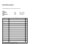
Technical publications ordering form
To order additional publications, please fill in a copy of this form and send it via mail to:
BULL CEDOC
357 AVENUE PATTON
B.P.20845
49008 ANGERS CEDEX 01
FRANCE
+33 (0) 2 41 73 72 66
+33 (0) 2 41 73 70 66
[email protected]
Designation
Reference
_ _
_ _
_ _ _ _
_
[ _ _ ]
_ _
_ _
_ _ _ _
_
[ _ _ ]
_ _
_ _
_ _ _ _
_
[ _ _ ]
_ _
_ _
_ _ _ _
_
[ _ _ ]
_ _
_ _
_ _ _ _
_
[ _ _ ]
_ _
_ _
_ _ _ _
_
[ _ _ ]
_ _
_ _
_ _ _ _
_
[ _ _ ]
_ _
_ _
_ _ _ _
_
[ _ _ ]
_ _
_ _
_ _ _ _
_
[ _ _ ]
_ _
_ _
_ _ _ _
_
[ _ _ ]
_ _
_ _
_ _ _ _
_
[ _ _ ]
_ _
_ _
_ _ _ _
_
[ _ _ ]
[ _ _ ]
Phone:
FAX:
E-Mail:
Qty
: The latest revision will be provided if no revision number is given.
NAME:
Date:
COMPANY:
ADDRESS:
PHONE:
E-MAIL:
For Bull Subsidiaries:
Identification:
For Bull Affiliated Customers:
Customer Code:
For Bull Internal Customers:
Budgetary Section:
For Others: Please ask your Bull representative.
FAX:
BLANK
BULL CEDOC
357 AVENUE PATTON
B.P.20845
49008 ANGERS CEDEX 01
FRANCE
REFERENCE
86 A1 70EG 01