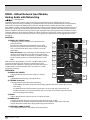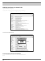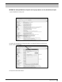
1
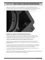
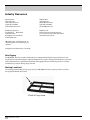
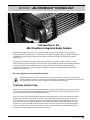
VT4887ADP
VT4887ADP-AN
Product User’s Guide
Compact Powered Line Array Systems
VT4887ADP-CN
VT4881ADP
VT4881ADP-AN
VT4881ADP-CN
2
VERTEC User’s Guide
TABLE OF CONTENTS
Section 1. Safety Instructions.....................................................................................Page 4
Section 2. Before You Begin .......................................................................................Page 7
Section 3. Introduction to VERTEC® DP Series
Compact Powered Line Array Systems ...................................................Page 8
Specifications by model
Section 4. VERTEC® DP Series Transducers ..............................................................Page 10
Section 5. Enclosure Care and Maintenance ............................................................Page 11
Section 6. Rigging and Suspension ...........................................................................Page 12
Safety Precautions
Industry Resources
Section 7. JBL DrivePack® Technology .....................................................................Page 15
AC Power Module, Electrical Information
Input Modules (DPIP, DPAN, DPCN)
Protective Jackets & installation
Section 8. HiQnet System Architect™ Software Configuration Guide .....................Page 26
Configuring your PC
Ethernet Network connections
Appendix A: Configuring CobraNet devices
Appendix B: Setting Microsoft Windows to standard font size
Appendix C: Setting Regional Language Options to US English
Section 9. JBL Professional Warranty .......................................................................Page 37
Section 10. Factory Contact Information ....................................................................Page 39
JBL Professional
3
SECTION 1 : SAFETY INSTRUCTIONS
Important
1. Read these instructions.
2. Keep these instructions.
3. Heed all warnings.
4. Follow all instructions.
5. Do not use this apparatus near water.
6. Clean only with dry cloth.
7. Do not block any ventilation openings. Install in accordance with the manufacturer’s instructions.
8. Do not install near any heat sources such as radiators, heat registers, stoves, or other apparatus
(including amplifiers) that produce heat.
9. Do not defeat the safety purpose of the polarized or grounding-type plug. A polarized plug has
two blades with one wider than the other. A grounding-type plug has two blades and a third
grounding prong. The wide blade or the third prong are provided for your safety. If the provided
plug does not fit into your outlet, consult an electrician for replacement of the obsolete outlet.
10. Protect the power cord from being walked on or pinched, particularly at plugs, convenience
receptacles, and the point where they exit from the apparatus.
11. Only use attachments/accessories specified by the manufacturer.
12. Use only with the cart, stand, tripod, bracket, or table specified by the manufacturer, or
sold with the apparatus. When a cart is used, use caution when moving the cart/apparatus
combination to avoid injury from tip-over.
13. Unplug this apparatus during lightning storms or when unused for long periods of time.
14. Refer all servicing to qualified service personnel. Servicing is required when the apparatus has
been damaged in any way, such as power supply cord or plug is damaged, liquid has been
spilled or objects have fallen into the apparatus, the apparatus has been exposed to rain or
moisture, does not operate normally, or has been dropped.
15. WARNING: To reduce the risk of fire or electric shock, do not expose this apparatus
to rain or moisture.
16. Do not expose this equipment to dripping or splashing and ensure that no objects filled with
liquids, such as vases, are placed on the equipment.
17. To completely disconnect this apparatus from the AC Mains, disconnect the power supply
cord plug from the AC receptacle.
18. The mains plug of the power supply cord shall remain readily operable.
4
VERTEC User’s Guide
�������
����������������������
������������
THIS APPARATUS CONTAINS POTENTIALLY LETHAL VOLTAGES. TO PREVENT ELECTRIC SHOCK OR
HAZARD, DO NOT REMOVE DRIVEPACK CHASSIS, INPUT MODULE OR AC INPUT COVERS. NO USER
SERVICEABLE PARTS INSIDE. REFER SERVICING TO QUALIFIED SERVICE PERSONNEL.
WATCH FOR THESE SYMBOLS
The lightning bolt triangle is used to alert the user to the risk of electric shock.
The exclamation point triangle is used to alert the user to important operating or
maintenance instructions.
FCC COMPLIANCE NOTICE
This device complies with part 15 of the FCC rules. Operation is subject to the following two conditions: (1)
This device may not cause harmful interference, and (2) this device must accept any interference received,
including interference that may cause undesired operation.
CAUTION: Changes or modifications not expressly approved by the party responsible for compliance could
void the user’s authority to operate the equipment.
CSA COMPLIANCE NOTICE
CSA Certification Applies to Amplifier Module Only
JBL Professional
5
JBL DRIVEPACK® DECLARATION OF CONFORMITY
Safety and EMC Compliance Specifications
EN 55103-1:1997 Electromagnetic Compatibility - Product Family Standard for Audio, Video, AudioVisual and Entertainment Lighting Control Apparatus for Professional Use, Part 1: Emissions
EN 55103-1:1997 Magnetic Field Emissions-Annex A @ 10 cm and 1 M
EN 55022:2003 Limits and Methods of Measurement of Radio Disturbance Characteristics of ITE:
Radiated, Class B Limits; Conducted, Class A
EN 55103-2:1997 Electromagnetic Compatibility - Product Family Standard for Audio, Video, AudioVisual and Entertainment Lighting Control Apparatus for Professional Use, Part 2: Immunity
EN 61000-4-2:1995 + A1:1999 & A2:2001 Electrostatic Discharge Immunity (Environment E2-criteria B, 4
kV Contact, 8 kV Air discharge)
EN 61000-4-3:2003 Radiated, Radio-frequency, Electromagnetic Immunity (Environment E2, criteria A)
EN61000-4-4:2005 Electrical Fast Transient/Burst Immunity (criteria B)
EN 61000-4-5:2001 Surge Immunity (criteria B)
EN 61000-4-6:1996 Immunity to Conducted Disturbances Induced by Radio-Frequency Fields (criteria A)
EN 61000-4-11:2004 Voltage Dips, Short Interruptions and Voltage Variation
UL 60065:2003, 7th edition: Audio/Video and Musical Instrument Apparatus for Household, Commercial
and Similar General Use
IEC 60065, 2001: Audio, Video and Similar Electronic Apparatus - Safety Requirements
CAN/CSA E60065-03: Audio, Video and Similar Electronic Apparatus – Safety Requirements
6
VERTEC User’s Guide
SECTION 2 : BEFORE YOU BEGIN
The VERTEC® DP Series systems covered by this manual are not intended for fixed installation
in outdoor or high moisture environments. Moisture can damage the speaker cone and surround
and cause corrosion of electrical contacts and metal parts. Avoid exposing the speakers to direct
moisture. Keep loudspeakers out of extended or intense direct sunlight. The driver suspension will
prematurely dry out and finished surfaces may be degraded by long-term exposure to intense ultraviolet (UV) light.
VERTEC® DP Series Compact Powered Line Array loudspeakers can be suspended with available
array frames (P/N VT4887-AF, VT4887-SF) or they can be ground-stacked. These systems can
generate considerable energy. When placed on a slippery surface such as polished wood or
linoleum, a single speaker may move due to its acoustical energy output. Precautions should be
taken to assure that the speaker does not fall off a stage or scaffold platform on which it is placed.
While it is unlikely that a ground-stacked array will move when properly attached to its array frame,
precautions should be taken to assure that the array assembly cannot fall from any surface on
which it is placed. Hearing damage, prolonged exposure to excessive SPL VERTEC® DP Series
loudspeakers are easily capable of generating sound pressure levels (SPL) sufficient to cause
permanent hearing damage to performers, production crew and audience members. Caution should
be taken to avoid prolonged exposure to SPL in excess of 90 dB.
Package Contents
• Product User’s Guide (this document)
• JBL DrivePack® compatible loudspeaker
• CD containing System Architect™ software (DPAN/DPCN only), DXF files, and spec sheets
• AC Power North America/Europe Cord-Set
• Protective Jacket Set
• Warranty Card
JBL Professional
7
SECTION 3 : INTRODUCTION TO VERTEC® DP SERIES
COMPACT POWERED LINE ARRAY SYSTEMS
Shown: VT4881ADP over VT4887ADP
VERTEC® DP Series Compact Powered Systems
The VERTEC DP Series compact models are part of a family of powered integrated audio loudspeaker
systems featuring the JBL DrivePack® amplifier modules, designed in cooperation with Crown International.
The JBL DrivePack features cutting-edge technology such as patented high efficiency Class-I power
amplifier circuitry. Loudspeaker components include patented JBL Differential Drive® woofers.
This guide covers the following models:
VT4881ADP.................................................... 1x18” subwoofer system
VT4881ADP-AN........................................... with optional DPAN network input module, analog audio
VT4881ADP-CN .......................................... with optional DPCN network input module, digital audio
VT4887ADP.................................................... 2x8” bi-amplified three-way full range system
VT4887ADP-AN........................................... with optional DPAN network input module, analog audio
VT4887ADP-CN .......................................... with optional DPCN network input module, digital audio
8
VERTEC User’s Guide
VERTEC DP SERIES, COMPACT POWERED SYSTEMS SPECIFICATIONS
Product Acoustics
VT4887ADP
VT4881ADP
Frequency Response (±3 dB): 67 Hz – 20 kHz
34 Hz - 125 Hz
Frequency Range (-10 dB): 55 Hz – 22 kHz
25 HZ - 160 Hz
Horizontal Coverage
Angle (-6 dB): 100 deg. nominal (500 Hz – 16 kHz)
Vertical Coverage
Angle (-6 dB): Varies with array size and configuration
Maximum Peak Output: 136 dB SPL, 1m
N/A
N/A
131 dB SPL, 1m
Transducer Sections
Low Frequency Two 2168H-1, 203 mm (8 in) dia., 76 mm
(3 in) Dual Coil, Differential Drive®, Direct
Cooled
Bandpass Nominal Impedance: 4 Ohms (LF woofers wired in parallel)
Mid & High Frequency: MID: Four 2104H 101 mm (4 in) with 25.4 mm
(1 in) dia. voice coil
HF: Two JBL 2408H 25 mm (1 in) exit compression drive, 38 mm (1.5 in) voice coil
Bandpass Nominal Impedance: 8 ohms (drivers wired in series-parallel)
One 2269G, 457 mm (18 in) dia., 100 mm
(4 in) Dual Coil, Differential Drive®, Direct
Cooled, 2000W Cont./8000W Peak
4 Ohms
N/A
N/A
System Electronics
DP Internal Amplification
Output (at load): DP2; 2200W Peak, 1100W Continuous
DP Output Topology: DP2; 2-Channel, Class-I
DP1; 3600W Peak, 1800W Continuous
DP1; 1-Channel, Class-I
Signal Processing: dbx Type IV Conversion System, Precision bandpass filters, limiting, pre-equalization
filters and automatic self-test functions
System Management: DSP based limiters for mechanical and thermal protection
Signal Input: F-XLR Active 20K Ohms Balanced, 10K Ohms Unbalanced
Signal Loop-Through: M-XLR (passive pass-through)
Controls: Precision 0.5 dB increment Detented 16 dB input attenuator
AC Power Operating Range: Auto Select 90-132/VAC 50/60 Hz
AC Line Voltage: 50/60 Hz, Auto-Detect; 120V/240V (±10%)
AC Input Connector: Neutrik PowerCon (Blue)
AC Power Loop-thru: Neutrik PowerCon (Gray)
AC Current Requirement: 4A per system at 120V, 3A per system at
240V
5A per system at 120V, 3.2A per system
at 240V
Enclosure
Box Construction: Wedge frustum 5 degree side angle enclosure. PlyMax™ engineered composite structure, DuraFlex finish, 2 handles
Rectangular enclosure. PlyMax™ engineered wood composite
structure. DuraFlex™ finish, 6 handles
Suspension System: S.A.F.E. hardware, integral hinge bars nest
in rigging tubes on box ends. Quick release
pins with restraining lanyards
S.A.F.E. hardware, as per VT4887ADP.
Suspend with VT4887-AF Array Frame.
Set of 4 hinge bars included with
VT4881ADP system.
Grille: Black perforated steel, foam backed
Dimensions (W x H x D): 787 mm X 279 mm X 563 mm
(31 in X 11 in X 22.1 in)
Net Weight: 39.7 kg (87.5 lb)
787 mm X 569 mm X 800 mm
(31 in X 22.4 in X 31.5 in)
62.2 kg (137 lb)
JBL Professional
9
SECTION 4 : VERTEC® DP SERIES TRANSDUCERS
2408H High Frequency Compression Driver
JBL’s 2408H features a lightweight neodymium magnet structure, annular
polymer diaphragm and a 1” exit. Coupled to a proprietary waveguide
engineered to be part of the system’s thermal-transfer mechanism, it is
designed to deliver crystal-clear sound with superb dynamic range. The 2408H
is an 8 Ohm device. Two are included in each VT4887ADP system.
2168H-1 Low Frequency Loudspeaker
The 2168H-1 is an 8” transducer engineered with JBL’s patented Differential
Drive® technology. These low frequency drivers dramatically reduce driver
weight while greatly enhancing all critical performance parameters: frequency
response, power output, and distortion. Differential Drive technology features
a unique design with heat sinks integrated into the cast aluminum frame for
a highly improved performance to weight ratio. The dual voice coil design
places the neodymium magnets inside the voice coil assembly, completing the
magnetic circuit without the heavy surrounding steel structure of conventional
drivers. 8 Ohm device.
For more information, see JBL Tech Note Vol. 1 Number 33, “Differential
Drive Transducers”
2269G Ultra Long Excursion, Differential Drive®
Low Frequency Drivers
Ultra Long Excursion 460mm (18”) transducer features 2000 watts continuous
(AES), 8000 watts peak power handling capacity. It’s the latest example of JBL’s
patented Differential Drive® dual voice-coil loudspeaker technology, fitted with
dual neodymium magnets, JBL’s exclusive Vented Gap Cooling™, and an ultrarobust composite cone with a peak-to-peak maximum excursion of 89 mm
(3.5”).
10
VERTEC User’s Guide
SECTION 5 : ENCLOSURE CARE AND MAINTENANCE
VERTEC DP Series enclosures are constructed of JBL PlyMax™, an exclusive hybrid engineered-wood
technology designed to reduce enclosure weight while offering exceptional panel rigidity with the appropriate
acoustical properties. The exterior of each enclosure is covered with JBL’s exclusive DuraFlex™ finish.
PAINTING JBL VERTEC DP SERIES SYSTEM PRODUCTS
Each JBL Professional VERTEC DP Series system model is readily paintable. The DuraFlex finish provides
a lightly textured surface that any household or industrial paint readily adheres to. The result is a speaker
enclosure that is able to blend unobtrusively into the decor of any stage set or environment.
Instructions for painting wood enclosures (do not paint the JBL DrivePack®):
1. Prepare the enclosure surface by cleaning and wiping off dust and film with a damp cloth. It may be
necessary to use a mild household cleaner to remove grease. Avoid using a cloth that will deteriorate over
the textured surface.
2. Apply as many coats of paint as is required. Application can be by rolling, brushing or spraying. Care must
be taken when painting the grille. Avoid any paint or type of application that will clog the open cells in the
foam of the front grille. Depending on the type of paint, it may not be wise to spray the grille.
3. For painting systems that are installed in environmentally-hostile locations, it is recommended that an
automotive paint should be used for maximum protection.
Note: for systems that will be transported on a regular basis, oil-based paints or Krylon-type spray paints will
give better long-term results than water-based Latex type paints.
JBL Professional
11
SECTION 6 : RIGGING AND SUSPENSION
Safety Precautions
Before attempting to suspend your speakers, read and understand the following safety information.
IMPORTANT RIGGING SAFETY WARNING!
The information in this section has been assembled from recognized engineering data and is intended for
informational purposes only. None of the information in this section should be used without first obtaining
competent advice with respect to applicability to a given circumstance. None of the information presented
herein is intended as a representation or warranty on the part of JBL. Anyone making use of this information
assumes all liability arising from such use.
All information presented herein is based upon materials and practices common to North America and may
not directly apply to other countries because of differing material dimensions, specifications, and/or local
regulations. Users in other countries should consult with appropriate engineering and regulatory authorities
for specific guidelines.
Correct use of all hardware is required for secure system suspension. Careful calculations should always be
performed to ensure that all components are used within their rated workload before the array is suspended.
Never exceed maximum recommended load ratings.
Before suspending any speaker system always inspect all components (enclosure, rigging frames, pins, etc.)
for cracks, deformations, corrosion, missing, loose or damaged parts that could reduce strength and safety
of the array. Do not suspend the speaker until the proper corrective action has been taken. Use only loadrated hardware when suspending VERTEC® DP Series loudspeakers.
12
VERTEC User’s Guide
Are You New to Rigging?
If you are new to rigging, you should do the following:
• Read and study JBL Technical Note Volume 1, Number 14: Basic Principles for Suspending Loudspeaker
Systems (available at http://www.jblpro.com/pub/technote/tn_v1n14.pdf ).
• Know the Rules for Safe Rigging.
• Attend a safe rigging seminar, such as that presented by professionals like Rigging Seminars™ or by
Chain Motor Hoist manufacturers like Columbus McKinnon Corp. (manufacturers of the C/M Lodestar).
• Meet and establish a relationship with a licensed mechanical or structural engineer. Get in the habit of
asking them questions instead of guessing about their answers. Learn from what they tell you.
• Meet and discuss this aspect of your business with your Insurance Agent.
• Research and understand the codes, practices, and requirements in the venues where you intend to
operate your sound system.
General Hardware Information
Any hardware used in an overhead suspension application must be load rated for the intended use.
Generally, this type of hardware is available from rigging supply houses; industrial supply catalogs and
specialized rigging distributors. Local hardware stores do not usually stock these products.
Attachment to Structures
A licensed Professional Engineer must approve placement and method of attachment to structures prior
to installation of any overhead object. The following performance standards should be provided to the
Professional Engineer for design purposes: Uniform Building Code as applicable, Municipal Building Code as
applicable, Seismic Code as applicable. Installation of hardware and method of attachment must be carried
out in the manner specified by the Professional Engineer. Improper installation may result in damage, injury
or death.
Rigging Hardware Inspection & Maintenance
Suspension systems are comprised of mechanical devices and, as such, they require regular inspection
and routine maintenance to insure proper function ability. JBL VERTEC® DP Series loudspeakers must
be inspected for fatigue at least annually. The inspection shall include a visual survey of all corners and
load bearing surfaces for signs of cracking, water damage, de-lamination, or any other condition that may
decrease the strength of the loudspeaker enclosure. Accessory rigging hardware provided with or for JBL
VERTEC DP Series loudspeakers must be inspected for fatigue at least annually. The inspection shall include
a visual material survey for signs of corrosion, bending or any other condition that may decrease strength of
the fastener. For other fittings used, refer to the manufacturer’s inspection and maintenance guidelines for
process.
JBL is not responsible for the application of its products for any purpose or the misuse of this information
for any purpose. Furthermore, JBL is not responsible for the abuse of its products caused by avoiding
compliance with inspection and maintenance procedures or any other abuse. Prior to suspending the
system, an expert, trained and experienced in flying loudspeaker systems should inspect all rigging parts and
components.
JBL Professional
13
Industry Resources
Allen Products
(562) 424-1100
1635 E. Burnett Street
Signal Hill, CA 90806
www.allenproducts.com
ATM Fly-Ware
(562) 424-1100
1635 E. Burnett Street
Signal Hill, CA 90806
www.atmflyware.com
M.A.N. Flying Systems
20 Sidar Road
Brook Road
Industrial Estate
Rayleight, Essex SS6 7XF U.K.
www.manfly.co.uk
McMaster Carr
Various locations through the U.S.A.
For a location near you, visit them online:
www.mcmastercarr.com
JBL Professional - Tech Note V1 No. 14
“Basic Principles for Suspending Loudspeakers”
www.jblpro.com/technote/tn_v1n14.pdf
Safe Rigging
The JBL VERTEC® DP Series arrayable loudspeakers are equipped with integral suspension hardware and
should only be suspended using the supplied equipment. The system is designed to facilitate the suspension
of the loudspeakers by a qualified person familiar with rigging hardware and industry practices. Improper
installation may result in damage, injury or death.
Working Load Limit
The working load limit (WLL) for any group (“array”) of JBL VERTEC DP Series system products is noted on
the appropriate VERTEC Array Frame.
VT4887-AF Array Frame
14
VERTEC User’s Guide
SECTION 7 : JBL DRIVEPACK® TECHNOLOGY
Introduction to the
JBL DrivePack Integrated Audio System
JBL DrivePack equipped loudspeakers are a family of fully integrated audio systems, coupling industryleading loudspeaker technology to a combination of comprehensive digital signal processing and advanced
amplifier technology, perfectly matched to the enclosures to deliver superb audio quality and powerful
performance.
The DrivePack is attached to the back of each DP-compatible loudspeaker enclosure, creating a seamless
electro-mechanical system that offers both convenience and portability along with the unmatched reliability,
accuracy and superb sound of JBL loudspeakers. The DrivePack includes onboard DSP functionality to
communicate readiness and operational status, including a self-test cycle and lighted indicators for fault
detection upon power-up.
DrivePack Signal-Processing & Amplification Unit
The DrivePack electronics unit is intended to be used when mounted to a speaker enclosure of 5/8”
minimum thickness of wood or composite material and with load impedances of 4 Ohms, 8 Ohms for low
and mid frequency channels, and 8 or 16 Ohms for the high frequency channel.
OPERATING INSTRUCTIONS
All that is required to get your DP compatible loudspeaker system up and running is to connect an AC power
source to the AC Power module via the Neutrik PowerCon™ inlet connector, and a full range line level audio
signal to the Input module via the AUDIO IN XLR connector.
Upon initial power-up of the DrivePack, the Blue Power LED will illuminate and the Green DP Ready indicator
(located to the left of the input module input level control) will flash during the boot-up and AC line autoselect soft-start process. The JBL DrivePack is equipped with Auto-Sensing Universal AC Voltage Selection
and can operate anywhere in the world that has an available 100-120VAC or 200-240VAC power source. On
the power-up sequence the JBL DrivePack® input module senses line voltage and sets the high voltage line
select relay within about 2 seconds. The system is ready for operation when the Green Ready LED on both
the AC Input module and DPIP module is steadily illuminated.
JBL Professional
15
AC POWER REQUIREMENTS
Standard JBL DrivePack systems are equipped with a DP multi-channel Crown Class-I power amplifier and
loudspeaker specific DSP electronics and require appropriate AC power.
CAUTION: In compliance with safety agency criteria and proper system operation, it is critical that the
system installer observe all electrical safety practices at all times and provide proper earth grounding for
all AC Power connections.
AC POWER CORD KIT
Convenience 120VAC North America NEMA 5-15 Edison type AC plug to PowerCon® connector and
240V Europe CEE 7/7 Schuko type AC plug to PowerCon connector cord sets are provided with this JBL
DrivePack product for light-duty shop testing or system configuration type use.
One spare gray Neutrik (P/N NAC3FCB) PowerCon connector is included in the AC Power Cord Set for your
convenience to create a pass-through AC power cable. To create a pass-through cable the system installer
may choose to simply cut off the AC plug from one of the provided AC cord sets and replace it with the
provided Gray PowerCon AC Outlet connector. Follow the wiring convention indicated in Table 1.
NOTE: Tighten set screws to 2.5Nm (1.8lb-ft) torque to prevent opening by hand.
USER-FABRICATED AC POWER DISTRIBUTION
System owners may choose to fabricate or purchase a custom AC Power cable infrastructure optimized for
their specific JBL DrivePack system configuration. See Table 1 for custom application wiring and connector
information.
NOTE: Parts not provided.
CAUTION: Do not exceed 80% current rating of any AC connector at any time! See AC Power Rating
Tables for current draw information.
Table 1. User-Fabricated AC Cable and Connector Information
AC Inlet Cable Connector
Neutrik PowerCon® NAC3FCA quick lock 3-pole A-type
cable connector for power inlet. Rated current per contact:
20 A (rms), Rated Voltage: 250VAC.
AC Outlet Cable Connector
Neutrik PowerCon® NAC3FCB quick lock 3-pole B-type
cable connector for power outlet. Rated current per contact:
20 A (rms), Rated Voltage: 250VAC.
Wiring
Cable: screw-type terminals or soldering nom. wire size/
contact: 2.5 mm² / 14 AWG
Wiring convention
Ground – Ground, Neutral – Neutral, AC Hot – AC Hot
With the two non-interchangeable types of connectors (A-type, B-type) it is impossible to produce a short
circuit. Mating connectors (combination) are identified by mechanical keyways and by color.
Table 2. Power Connector Coding
A-type (POWER INLET);
Cable connector: Blue
B-type (POWER OUTLET)
Cable connector: Gray, with
Blue bushing
16
VERTEC User’s Guide
DP2 AC Power Ratings
Description
120VAC
240VAC
Idle (Sleep Mode)
< 20W
Quiescent Power Draw
< 75W
1/8th Power, Pink Noise (UL/CSA)
1/3rd Power, Pink Noise
400W, 4A rms
400W, 3A rms
8A
4.6 A
Maximum Power Draw
Inrush Current
3950W
Inrush current limiting via PTC soft-start
AC Power Module Connectors: 12A Max, 100-120VAC/220-240VAC, 50-60 Hz. Class 1
Wiring
Inlet Connector Rating
4A
3A
Outlet Connector Rating
8A
9A
120VAC
240VAC
16 AWG
(1.5 mm2)
DP1 AC Power Ratings
Description
Idle (Sleep Mode)
< 10W
Quiescent Power Draw
< 60W
1/8th Power, Pink Noise (UL/CSA)
1/3rd Power, Pink Noise
600W, 5A rms
600W, 3.2A rms
9A
6A
Maximum Power Draw
Inrush Current
4500W
Inrush current limiting via PTC soft-start
AC Power Module Connectors: 12A Max, 100-120VAC/220-240VAC, 50-60 Hz. Class 1
Wiring
Inlet Connector Rating
5A
3.2A
Outlet Connector Rating
7A
8.8A
16 AWG
(1.5 mm2)
Line Voltage Selection: The DrivePack® features an international Auto-Sensing power supply and will
automatically select the correct operating voltage range window. Automatic voltage selection is between 100120VAC and 200-240VAC operation, 50/60Hz.
Line Voltage Tolerance: The amp will operate normally (with expected de-rating in power output during low
line conditions) over a range of 100-120VAC +/-10% or 200-240VAC +/-10% AC input voltage. The amp will
shut down for voltages below nominal line and self protect for over-voltage beyond 15% nominal line.
CAUTION: Continuous voltages 10% beyond high line at either 120VAC or 240VAC operation ranges can
disrupt performance of the JBL DRIVEPACK! To avoid activation of amplifier low line/high line protection
which will interrupt audio performance, the system operator should maintain AC supply voltages within
the rated voltage windows.
JBL Professional
17
AC Power Module
POWER Indicator:
Blue LED – located near power inlet lights when AC power is applied.
Amp READY Indicator:
Green LED near power inlet, ON during normal operation, long pulse
during sleep mode.
Sleep Mode:
If audio input signals are not detected for 2 hours, the amplifier will
go into sleep/standby mode; the amplifier output section is turned
off while the supply powering the DP Input Module and DSP logic
remains active. This mode reduces current draw and heat loss.
While in sleep mode the READY indicator pulses slowly. Recovery
from sleep mode is instantaneous when an audio signal is detected
.
Thermal Management:
JBL DrivePack® systems are cooled by Passive Convection. No fans
are used in any part of the thermal management system. To maintain
efficient cooling it is a good practice to assure open space around the DrivePack units.
Operating Temperature:
The system will remain touchable during quiescent operation and will not provide a burn hazard during any
operating condition.
Input Module Controls, Indicators and Connectors
JBL DrivePack® systems are equipped with a modular input bay and input modules are available in three
versions in the VERTEC DP Series: the DPIP, DPAN and the DPCN.
Audio Signal Distribution
Connecting source audio signals to the input modules on JBL
DrivePack systems is similar to daisy-chaining multiple external
amplifier channels together.
Assuming an output device source impedance of 100 Ohms and a
10:1 load to source ratio, up to 20 JBL DrivePack units typical can be
linked together on one output source without using a distribution
amp.
NOTE: Please refer to VERTEC DP Series spec sheets for additional
features and specifications of the DPIP, DPAN and DPCN input
modules.
18
VERTEC User’s Guide
DPIP – Standard Input Module
See Figure 1
The standard DPIP input module features analog audio inputs and sophisticated onboard digital signal processing
technology. Precision Bandpass limiting, pre-equalization filters and automatic self-test functions ensure optimized
performance. JBL engineers have calibrated DSP speaker management and limiter parameters to insure smooth
phase response and transfer function curves right out of the
box.
CONTROLS
1) Subwoofer Filter Enable Select Switch
a) Momentary, Enables or disables the selected
function. On subwoofer applications the low-pass
frequency is set to 80 Hz and for full range systems
the high-pass is raised to 80 Hz. (Knee shape and
slopes are model dependent).
7) Input Sensitivity/Attenuation Control:
a) 16 dB Precision Detented rotary control, 0.5 dB
steps. Sensitivity +4 dBu nominal (+23 dBu clip)
with the control fully counter clockwise, and -10
dBv nominal (+4 dBu clip) with the control fully
clockwise.
INDICATORS
2) Subwoofer Filter Enable
a) Orange LED, illuminates when the
function is enabled.
�
�
�
�
�
�
�
�
3) FAULT
a) Red LED, illuminates during any
fault condition.
�
4) THERMAL PROTECTION
a) Orange LED, illuminates during
thermal limiting:
ai) PULSING indicates first stage of thermal
Figure 1
limiting, amplifier output level is reduced to prevent overheating.
aii) FLASHING indicates transducer thermal limits have been exceeded. Further reduction in
output level is applied.
aiii) SOLID illumination indicates thermal protection is in the third stage of
protection and amplifier shut down may occur if immediate
action is not taken to correct the external reason for excessive heating of the amplifier.
5) Ready
a) Green LED, illuminates when the system is
ready for operation.
6) SIGNAL/CLIP
a) (Signal) Green LED, detects input signal above the threshold set at –70 dBu. b) Yellow indicates
that the audio drive signal has exceeded limits preset in DSP on any channel and compression/
limiting is active.
c) (Clip) Red LED, Clip detection monitors input, DSP, and each amplifier output channel. The LED
changes from Green to Red when clipping THD at any point is detected.
CONNECTORS
8) Audio In
a) F-XLR Active 20K Ohm Balanced, 10K Ohm Unbalanced.
b) Pin 2 Hot (Positive voltage produces outward cone motion of L.F. Transducers).
9) Audio Out
a) M-XLR Passive Audio Pass-through.
b) Pin 2 Hot (Positive voltage produces outward cone motion of L.F. Transducers).
JBL Professional
19
DPAN – HiQnet Network Input Module,
Analog Audio with Networking
See Figure 1a
The DPAN input module features analog audio inputs and sophisticated onboard digital signal processing
technology. Precision band pass limiting, pre-equalization filters and automatic self-test functions ensure optimized
performance. In addition, the DPAN input module adds 100 Mb Ethernet networking functionality and HiQnet
compatibility. It enables remote control and monitoring via HiQnet System Architect™ software. Network Control and
Monitoring is enabled by the JBL DP-DCP (DrivePack Device Control Panel) supplied within HiQnet System Architect.
Network capabilities include monitoring of status, input and output levels, clipping, temperature, load faults and gain
reduction. Additional control features available in software include load supervision, dynamic processing, ten internal
user defined presets, delays, onboard noise and sine-wave generators, network device event logging, and user alert
messaging.
CONTROLS
1) ENABLE ALT PRESET button
a) Momentary, Enables or Disables the selected function.
Factory ALT Preset:
On subwoofer applications, the subwoofer low-pass filter
frequency is set to 80 Hz and for full range systems the highpass is raised to 80 Hz. (Knee shape and slopes are model
dependent).
Internal Controls - Input Sensitivity 2-Position Switch: Located
on the back side of the front panel, full output is achieved by
selecting either +4 dBu in one position or +20 dBu in the other
position. Switch positions are marked with silkscreen on the
PWB.
NOTE: Product is shipped factory set to the +20 dBu switch position
to provide optimal input gain structure and headroom for most
professional audio equipment. Changing the sensitivity switch to the
+4 dBu setting is not recommended unless connection to -10 dBV
equipment is required.
��
��
�
��
�
��
�
�
�
�
�
INDICATORS
2) ENABLE ALT PRESET
a) Orange LED illuminates when the function is enabled.
�
��
3) FAULT
a) Red LED illuminates during any fault condition.
4) THERMAL Protection
a) Orange LED illuminates during thermal limiting:
ai) FLASHING indicates first stage of thermal limiting, amplifier output level is reduced to prevent
overheating.
aii) SOLID illumination indicates thermal protection is in the second stage of protection and
amplifier shut down may occur if immediate action is not taken to correct the external reason for
excessive heating of the amplifier.
5) READY
a) Green LED, illuminates when the system is ready for operation
6) SIGNAL/CLIP
a) (Signal) Green LED, detects input signal above the threshold set at –70 dBu
b) (Clip) Red LED, Clip detection monitors input, DSP, and each amplifier output channel. The LED
changes from Green to Red when clipping THD at any point is detected.
11) NETWORK 100MB ACTIVITY
a) The Activity LED indicates data activity on the network line.
20
VERTEC User’s Guide
Figure 1a
12) NETWORK 100MB LINK
a) The LINK LED indicates that the data is at 100 Megabits.
13) DATA
a) Yellow LED Flashes for received data packet addressed to this DPAN device.
CONNECTORS
XLR connectors allow connectivity to an analog audio source. This input can be used as a back-up to CobraNet®
or as a primary audio source in the absence of CobraNet®.
8) AUDIO IN
a) F-XLR Active 20K Ohm Balanced, 10K Ohm Unbalanced.
b) Pin 2 Hot (Positive voltage produces outward cone motion of L.F. Transducers).
9) AUDIO OUT
a) M-XLR Passive Audio Pass-through.
b) Pin 2 Hot (Positive voltage produces
outward cone motion of L.F. Transducers).
10) HiQnet 100MB NETWORK Connector
a) The network connector is a standard RJ-45 connector that allows the DPAN to connect to an Ethernet
network. Connection is made using a standard Category 5 cable to a network switch port.
MAC ADDRESS WINDOW
14) The MAC address is a unique 12 digit hexadecimal hardware address assigned to every network device
by the manufacturer and is not changeable by the user. This unique physical address enables each device on the
network to identify and communicate directly with other devices connected to the network.
JBL Professional
21
DPCN – Optional HiQnet Network Input Module
with CobraNet™ Digital Audio
See Figure 1b
In addition to all features included on the DPAN, the DPCN input module adds CobraNet and offers
the ability to direct up to 64 audio channels on one network, with digital audio and remote control and
monitoring via Ethernet combined on a single cable.
DPCN modules include the option to use an analog input as a backup audio source providing complete
reliability and flexibility to cover any situation.
The HiQnet System Architect™ software user interface provides remote access to digital speaker preset files
in the JBL DrivePack®. As with the DPAN, user-addressable features include ten user defined presets, up
to 2 seconds of delay per channel, onboard noise and sine-wave generators, network device event logging,
and user alert messaging.
CONTROLS
1) ENABLE ALT PRESET button
Momentary, Enables or disables the selected function. Factory ALT Preset: On subwoofer applications
the subwoofer low-pass filter frequency is set to 80 Hz and for full range systems the high-pass is raised
to 80 Hz. (Knee shape and slopes are model dependent).
2) INTERNAL CONTROLS - Internal +4 dBu or +20 dBu sensitivity select switch. See NOTE on DPAN for details.
INDICATORS
2) ENABLE ALT PRESET
a) Orange LED, illuminates when the
function is enabled.
3) FAULT
a) Red LED illuminates during any fault condition.
4) THERMAL Protection
a) Orange LED illuminates during thermal
limiting: See DPAN for details.
5) READY
a) Green LED illuminates when the system is
ready for operation.
�
��
�
�
6) SIGNAL/CLIP
a) (Signal) Green LED indicates a detected input signal
above the threshold set at –70 dBu.
b) (Clip) Red LED indicates clipping
at any point is detected.
�
11a & 11b) CobraNet™
NETWORK 100MB ACTIVITY
a) The Activity LED on the RJ-45 connectors
display network information concerning the Ethernet
and CobraNet™ connections.
ai) Flashing Green indicates network activity.
aii) Flashing Orange on Activity and Link LEDs
simultaneously indicates a network FAULT.
�
�
�
�
12a & 12b) NETWORK 100MB LINK
a) The LINK LED on the RJ-45 connectors displays network information concerning the Ethernet and
Figure 1b
CobraNet™ connections.
ai) Solid Orange indicates the device is linked to a CobraNet™ Network.
aii) Flashing Orange on the LINK indicator-only indicates this device is the CobraNet™ Conductor.
aiii) Flashing Orange on Activity and Link LEDs simultaneously indicates a network FAULT.
13) DATA
a) Yellow LED Flashes for received data packet addressed to this DPAN device.
22
VERTEC User’s Guide
���
���
���
���
���
���
��
CONNECTORS
XLR connectors allow connectivity to an analog audio source. This input can be used as a back-up to
CobraNet™ or as a primary audio source in the absence of CobraNet™.
8) AUDIO IN
a) F-XLR Active 20K Ohm Balanced, 10K Ohm Unbalanced, PIN 2 HOT.
9) AUDIO OUT
a) M-XLR Passive Audio Pass-through.
10a & 10b) CobraNet™ PRIMARY and SECONDARY NETWORK CONNECTORS
a) The dual RJ-45 CobraNet™ connectors allow a Primary & Secondary connection to the 100Mb Ethernet
network and provide device control and monitoring as well as CobraNet™ digital audio on the same
CAT5 cable. Should the Primary connection (10a) lose Link activity with the network, the DPCN will
automatically switch to the Secondary connection (10b) to ensure uninterrupted audio and control/
monitoring. Use the Primary connector as your main CobraNet™ and Ethernet port.
NOTE: These dual RJ-45 connectors CANNOT be used to daisy-chain Ethernet cables. An external
Ethernet Switch is required to “distribute” Ethernet connections. See Section 7 for details.
MAC ADDRESS WINDOW
14) The MAC address is a unique 12 digit hexadecimal hardware address assigned to every network
device by the manufacturer and is not changeable by the user. This unique physical address
enables each device on the network to identify and communicate directly with other devices
connected to the network.
JBL Professional
23
Protective Jackets for Input and AC Power Modules
Each VERTEC Series system is supplied with a pair of protective jackets that are designed to fit snugly onto the input
and AC power modules of the DP2 or DP1 electronics assembly. These jackets are made of reinforced, weatherized
nylon fabric with Velcro attachment strips and drawstrings to secure the opening once installed. They can be used by
the system operator or installer to provide a degree of protection from dirt, dust, and moisture and to protect cables
and connectors.
Protective Jacket Installation
Complies with IEC 60529 - IPX-3, not evaluated for outdoor use.
1. Remove two protective jackets from the protective jacket kit. To
install, open the jacket by “unzipping” the Velcro strip and locate two
smaller Velcro tabs on the inside of the jacket. See Figure 1
Figure 1
2. Open the center Velcro tab and insert through the opening in the
module riser. See Figure 2
Figure 2
3. Next, wrap the left side of the cover around the bottom edge of the
riser. Insure that the bottom of the jacket is tucked into the riser ring
crevice between the top of the chassis and the bottom of the riser ring
rim. See Figure 3.
4. Pull the second Velcro tab through the second opening in the riser
ring. See Figure 3
Figure 3
24
VERTEC User’s Guide
5. Wrap the opposite end of the open jacket around the riser ring as
shown in Figure 4. Be certain that the bottom of the protective jacket
is tucked-in all the way around the riser ring as shown.
Figure 4
6. “Zip” up the Velcro strip and pull the draw cord closed as required
as shown in Figure 5. The protective jacket should now be securely
fastened all the way around the riser ring at the bottom and top end of
the jacket and should be closed securely forming a protective closure
around the connector panel.
7. Repeat the process for the other connector panel.
Figure 5
JBL Professional
25
SECTION 8 : SYSTEM ARCHITECT SOFTWARE
The VERTEC DP Series has optional advanced network control capabilities with the DPAN or DPCN input
modules. VERTEC DP Series loudspeaker systems so equipped utilize Harman Professional’s HiQnet™
protocol to enable a complete configuration, control, and monitoring solution. HiQnet protocol provides
remote access to loudspeaker preset files in the JBL DrivePack® input modules making system setup
easy yet powerful, via the DrivePack Software Device Control Panel with its intuitive, user-friendly graphical
interface. HiQnet System Architect™ provides complete software control of not only your JBL DrivePackequipped loudspeakers, but also other HiQnet-compatible audio components within the total system.
It is recommended to visit www.harman.com for the most up to date version of HiQnet System Architect.
QUICK-START CONFIGURATION GUIDE
For JBL DrivePack-equipped loudspeaker Systems using System Architect software
INTRODUCTION:
This guide applies to all JBL loudspeaker models powered by DrivePack DP1, DP2 or DP3 amplifier
assemblies which incorporate DPAN or DPCN input modules.
Each loudspeaker must be connected to a 100BaseT Ethernet switch using a standard CAT-5 cable. The
control computer which will run System Architect must also be connected by a 100BaseT connection to a
switch on the same physical network.
If managed Ethernet switches are a part of the network, additional knowledge of TCP/IP protocols and
Ethernet-switch manufacturer-specific configurations may be required. This is beyond the scope of this
document. It is assumed that unmanaged switches are used in the networking examples discussed below.
Special requirements exist for CobraNet™ - compliant products using the DPCN input module. This is
addressed in Appendix A.
A Glossary of networking terminology used is provided at the end of this document.
AS-SHIPPED ETHERNET CONFIGURATION:
Each loudspeaker product is shipped from the JBL factory with the following configuration:
- DHCP is enabled. (See glossary for details)
- Auto IP address negotiation is enabled (See glossary for details)
- Auto HiQnet device setting is enabled. (See glossary for details)
- The default IP address for all products shipped is 169.254.127.1 with subnet mask 255.255.0.0
QUICK-START: CONFIGURING YOUR PC WITH SYSTEM ARCHITECT™ SOFTWARE:
1) Install System Architect software on the Microsoft Windows 2000 or XP-equipped computer that will
control/monitor the HiQnet™ - compliant products.
2) Note that System Architect will only display graphics correctly when the Windows PC display is set to
standard, small font size. If Windows is set to “large” fonts, then the displays within System Architect may
become unreadable. To correct this problem change Windows to the standard font size. (See Appendix B for
details)
3) Note that System Architect will only display graphics correctly when the Windows PC. Regional and
Language settings are set to standard US English language. If Windows is set to any language other than
US English, objects in custom control panels will not display or function properly. To correct this problem
change Windows to the standard font size. (See Appendix C for details)
4) If you are using a CobraNet™ - compatible product see Appendix A for special instructions now before
proceeding further.
26
VERTEC User’s Guide
QUICK-START -- CONNECTING PC TO A JBL HiQNet DEVICE FOR THE FIRST TIME:
If this your first experience connecting a control computer running System Architect to a HiQnet-compliant
JBL product, then this initial test configuration will be useful. It will greatly help to resolve simple networking
issues before you connect to multiple devices or connect to a larger network:
Step 1) Connect one networked loudspeaker to an unmanaged 100BaseT network switch with a standard
CAT5 cable. Don’t apply AC power to the loudspeaker just yet.
Step 2) Connect the control computer to the Ethernet switch with a standard CAT5 cable.
Setting up a Simple Isolated Ethernet Network Using DHCP
In this configuration DHCP will automatically assign an IP address to the device on the network and your
computer.
Step 1) Open Network Connections on your computer and confirm that DHCP is Enabled. To do this
click Start, point to Settings, click Control Panel, and then double-click Network Connections. When
your Network Connections Window opens, double click on the Local Area Network icon. A Local Area
Connections Status window will open. Click on the Properties button and the Local Area Connection
Properties window open. Next scroll through the items window, select the Internet Protocol (TCP/IP) item
and click on the Properties button. The Internet Protocol (TCP/IP) Properties window will open. Select the
“Obtain an IP address automatically” option. Click OK through all your open network windows to close
them.
Step 2) Apply power to your JBL DrivePack and wait for it to boot up. With DHCP enabled, the DrivePack
and your computer should both automatically negotiate an IP Address.
Step 3) Launch System Architect. The DrivePack system should appear in the Venue View within a few
minutes.
Step 4) If nothing comes up, you should first check that your System Architect™ application has the
‘Network Active when the application starts’ and ‘Auto Populate venue view with detected devices’ boxes
checked; these are found in the Tools menu under Options/General Network Information.
Step 5) If Auto Populate is checked and the network is active (look at the network status icon located at
the bottom left corner of the Venue View window) and the devices are still not showing in the Venue View,
select the Network Wizard in the Tools menu and change the IP address of the devices so they can be on
the same network as your computer.
Set up with a Static IP address
Step 1) Go back through Step 1 above, except select “Use the following IP Address:’ option.
Step 2) Change the TCP/IP address of the control computer to 169.254.1.y and change the subnet mask
set to 255.255.0.0.
Note: The placeholder “y” in the last segment of the IP address represents a number anywhere in the range
of 1 to 254. The only requirement in your number selection is that no two devices on the same network can
share the same IP address. Depending upon PC operating system configuration a reboot may be needed
now.
Step 3) Avoid connecting the switch to any other Ethernet equipment other than the PC and the
loudspeaker just yet. You’re creating a network with only two devices -- the PC and the loudspeaker. This is
useful for a first test as it avoids any additional networking configuration issues.
JBL Professional
27
Step 4) Now launch System Architect in Windows. Once you see the Venue View of System Architect
appear, then proceed as follows.
Step 5) Verify that the HiQnet™ network is active by observing the network status icon located at the
bottom left of the Venue window. The icon should indicate “Network Active”. If it shows inactive status,
double click on the icon and the network will activate.
Step 6) Power up the loudspeaker connected to the network. Recheck the network status and verify that
the HiQnet network is Active. The loudspeaker will automatically determine an IP address and a HiQnet
Address. This can require up to 2 minutes in some cases. Once completed an Icon in the venue view will
appear representing the JBL Loudspeaker system connected to the network.
Step 7) Now double-click on the JBL loudspeaker to see the product specific control panel within System
Architect. From here you can control and change parameters and configuration of the JBL loudspeaker as
required.
ALTERNATE QUICK-START -- USING SYSTEM ARCHITECT’S NETWORK WIZARD:
Step 1) Once you have connected a powered up one DrivePack device to the network, verify that the
HiQnet network is active by observing the network status icon located at the bottom left of the Venue
window. The icon should indicate “Network Active”. If it shows inactive status, double click on the icon and
the network will activate.
Step 2) On the menu bar of System Architect™, click on Tools and then select Network Wizard. The
Network Wizard will open up. Click on Next to go to the next screen.
Step 3) The Wizard will detect the device on the network and a device icon appears in the Wizard window.
Select it and then click on the Configure button at the bottom of the screen.
Step 4) The ‘Configure Node’ window will open. Uncheck the ‘Use DHCP” button and verify that the
‘Readdress Automatically’ box at the top of the screen is unchecked.
Step 5) Exit the wizard by clicking on Finish.
Step 6) The JBL loudspeaker system will have appeared in the System Architect Venue view by this time.
Now double-click on the JBL loudspeaker to see the product-specific device control panel within System
Architect. From here you can control and change parameters and configuration of the JBL loudspeaker as
required.
WORKING WITH A NETWORK OF MULTIPLE JBL DEVICES:
Network Setup with DHCP
With the computer set to DHCP Enabled, connect devices to the network and apply power to devices one
or two at a time. The devices should AUTO-IP and populate Venue View as they are discovered by the
network. If they do not or seem to take too long to come up on the network, go back and use Static IP.
Static IP
Step 1) After completing the quick start procedure with one DrivePack device go back and verify that the
host PC’s Static IP address is set to an address in the auto IP range, such as:
IP Address:
169.254.1.Y (Y is a number between 1 and 254)
Subnet Mask: 255.255.0.0
28
VERTEC User’s Guide
Step 2) With System Architect running in Windows, power up the remaining loudspeakers connected to
the network one or two at a time. System Architect will automatically determine an IP address and a HiQnet
Address for each loudspeaker on the network assuming the devices populating the network are new units
(DHCP ENABLED). This can require up to 2 minutes in some cases. Once completed an Icon in the venue
view will appear representing the JBL Loudspeaker system connected to the network.
Step 3) If System Architect fails to recognize network devices within about two minutes, make sure all of
your connections are good and verify IP addressing. Launch the Network Wizard and repeat steps 3 - 4 in
the above procedure.
Note: If a device does not auto populate in Venue View or come up in Network Wizard, it is possible that
the device may have been previously configured for a subnet out of the IP range of your network. To find
these network devices you may need to launch Crown’s TCP/IQ utility that is bundled with System Architect
software. The TCP/IQ utility will find any device present on the network and will allow you to reconfigure the
device IP address and subnet mask to the same range as your network.
DISABLE DHCP/AUTO HIQNET ADDRESS IN SYSTEM ARCHITECT™:
Step 1) Click on any previous VP Series icons showing in venue view, and press the Delete key.
Step 2) Select Menu TOOLS->NETWORK WIZARD, click NEXT
Step 3) The master computer should discover the HiQnet™ products powered up on the network. If not,
please make sure all of your connections are good. and verify IP addressing.
Step 4) Once the Network Wizard Utility has launched and found devices on the network, select a single
component (It will highlight) - click on the CONFIGURE button located on the bottom of the window.
Step 5) System Architect will have detected the device, automatically assigned a HiQnet address and
disabled the “Readdress Automatically” function. You can manually assign a HiQnet address if desired.
Step 6) Un-check the box labeled “Use DHCP”
Step 7) The IP Address entry box will un-dim.
Step 8) In the Set Address window, set up a Static IP address—The IP address consists of a set of 4 threedigit numbers separated by a dot and must be unique. Network wizard will have already assigned an IP
address in the 169.254.X.Y range. You can start by leaving the IP address assigned by network wizard
or perhaps just change the X (third) number segment value to the same number in all devices. Start with
an address for example 169.254.1.Y. Enter the same number sets in the Subnet mask field for all of the
components as well as the master computer. Set the HiQnet address on each device sequentially. You can
change the IP address to a completely unique range at a later time, for example 126.126.0.Y or 192.168.1.Y
etc. You may want to create a network system log and write down all of your device IP addresses in your log
for future reference.
Step 9) Click OK. The Configure Node window will close.
Step 10) Repeat the procedure for all remaining devices on the network.
JBL Professional
29
30
VERTEC User’s Guide
GLOSSARY OF TERMS
Auto HiQnet Address: When devices boot up, System Architect software, when configured to do so, will
automatically negotiate and assign a unique HiQnet™ address to each device. The devices will then keep this address
until there is a conflict at start up or the user manually assigns the device a new address.
Auto-IP Address: Devices and computers, if set to use a DHCP server, and a DHCP server is not present on the
network, will automatically negotiate a default IP address in the form of 169.254.xxx.xxx. This can cause problems if
you have some devices or PC’s set with static IP addresses. It is possible that addresses manually assigned to Static
IP devices may intentionally fall outside of the default Auto-IP address range and may now be on a separate subnet
and will no longer be able to communicate with devices in the Auto-IP address range. However, if there isn’t a
DHCP server on the network, then having all devices/PC’s using an Auto-IP address will not cause any problems. In
summary: all devices and PC’s on a network will need to exist on the same subnet, whatever that may be.
DHCP: (Dynamic Host Configuration Protocol) An established Ethernet protocol for assigning IP addresses
automatically to physical hardware devices. A DHCP server must be present on the network to provide an IP address
to each device when power is applied. With dynamic (DHCP) addressing, a device might have a different IP address
every time it connects to the network. If a DHCP Server is not installed on the network, a computer will place a
default network ID (See Auto-IP Address) into the TCP/IP address and Subnet Mask.
HiQNet: The networking protocol established by Harman Professional to provide communication between products
for the purposes of: control, monitoring, and providing interaction between products. The protocol is independent of
the physical connection type. Typical physical connections include: Ethernet, USB, RS232, RS422, Infrared, and others.
For info go to http://www.harmanpro.com/hiqnet/
HiQnet Address: The HiQnet™ address is a unique number that allows System Architect software, the PC in use, and
the connected devices, to keep track of each other on the network. The HiQnet address is completely independent of
Ethernet IP addresses.
IP Address: (Internet Protocol address) Identifier for a computer or device on a TCP/IP network. Each device in
a network has its own identifying IP address. Example: 169.254.17.42. Networks using the TCP/IP protocol route
messages based on the destination’s IP address. An IP address is made of four numbers separated by periods. Each
number can be zero to 255. The last number can never be a zero or 255. For example, 126.126.17.1 could be an IP
address. 126.126.17.0 would not be a valid IP address.
Subnet Mask (short for Subnetwork Mask): Large networks may require subdivision into smaller groups or
subnets to keep the network more manageable. A subnet is a portion of a network that shares a common address
component. On TCP/IP networks, subnets are defined as all devices whose IP addresses have the same prefix.
For example, all devices with IP addresses that start with 126.126.126. would be part of the same subnet. IP networks
are divided using a subnet mask. A mask is a filter that selectively includes or excludes certain values. Values that
do not conform to the mask are not visible to each other. A mask is used to determine what subnet an IP address
belongs to. An IP address has two components, the network address and the host address. Like IP addresses, a
subnet mask contains four bytes (32 bits) and is often written using the same “dotted-decimal” notation. A very
common default subnet mask for example is 255.255.0.0 A subnet mask neither works like an IP address, nor does it
exist independently from them. Instead, subnet masks accompany an IP address and the two values work together.
Applying the subnet mask to an IP address splits the address into two parts, an “extended network address” and
a host address. The subnet mask is the network address plus the bits reserved for identifying the subnetwork.
Dividing a network into subnets is useful for both security and performance reasons.
System Architect: A software application for use on Windows PC’s that provides control of HiQnet compliant
products. System Architect integrates HiQnet-compliant products within a unified control application program. This
program allows grouping, cutting and pasting of settings, custom control panels, and more. It integrates products
from Harman Professional brands using the HiQnet protocol.
JBL Professional
31
APPENDIX A: CONFIGURING COBRANET
General
CobraNet is a licensed technology developed by Peak Audio, Inc. consisting of proprietary communications
protocol, firmware and hardware. It allows reliable, deterministic (i.e. real-time) transmission of high quality
(i.e. un-compressed) digital audio over standard 100Base-T Fast-Ethernet network. CobraNet will also operate on faster versions of Ethernet (e.g. Giga-bit and 10Giga-bit).
A CobraNet system is comprised of CobraNet devices and the Ethernet network that connects them. PCs or
other system controllers may also be connected to the network for setup but are not required for operation.
Ethernet
Ethernet is a hardware and signaling specification developed by Xerox in 1970 for data networking. The IEEE
(Institute of Electrical and Electronics Engineers) standardized the technology in the IEEE 802.3 standard
and its variants.
With over 50 million nodes installed, Ethernet is easily the most dominant data networking technology in use
today. It is carried over inexpensive CAT-5 UTP cables or fiber. Typical Ethernet cabling limitations are: 100
meters over CAT-5 copper cable, 2 kilometers over multimode fiber.
The CobraNet™ Device
Each CobraNet device embeds specialized hardware and firmware. The hardware includes a standard
100MB Fast-Ethernet interface along with custom high-speed DSP chips and clock circuitry. The DSP and
its embedded software are used to encode and decode the Ethernet network messages using the proprietary protocol. The clock circuitry is used to accurately decode the system master clock timing needed for
high-quality real-time audio delivery.
Audio Specs
All CobraNet devices operate at a fixed sample rate of 48kHz. The audio data may be transmitted at 16, 20
or 24 bit data as desired. For reliable operation, each CobraNet device must implement transmit and receive
buffering. This buffering is fixed at 256 samples and results in a minimum audio network latency of 5.333ms.
(256 samples at 1/48kHz per sample)
Bundles and Audio Channels
Routing of digital audio between CobraNet devices is accomplished through Bundles. A Bundle is the name
given to the proprietary encoded message (a.k.a. “packet”) transmitted between CobraNet devices that include multiple channels of digital audio. Each CobraNet device can transmit and receive up to four Bundles.
Each Bundle includes up to 8 Audio Channels. Therefore, each device is capable of transmitting and receiving up to 32 Audio Channels to and from the network.
Bundles can be transmitted using Ethernet multicast or Ethernet unicast methods. Multicast Bundles are
sent to all CobraNet devices on the network, while unicast Bundles are sent to one and only one CobraNet
device. Since each device can send and receive four Bundles, great flexibility is allowed in the routing of
audio over the network. Up to 8 multicast Bundles (64 Audio Channels) can be transmitted on a simple repeater based Ethernet network. Up to 4 multicast Bundles (32 Audio Channels) along with up to 421 unicast
Bundles (>3000 Audio Channels) can be transmitted simultaneously on a full-duplex switch-based CobraNet
network.
Assignment of Bundles is accomplished through the selection of a Bundle number. Bundles between 1-255
are always multicast, while Bundles between 256 - 65,279 are unicast. Bundle assignments must not be
duplicated. Only one CobraNet transmitter is allowed per bundle.
The Conductor
On a CobraNet network, the Conductor coordinates transmission of audio packets throughout the entire
network. When two or more CobraNet devices are interconnected properly, one of them will be selected the
Conductor based on their respective Conductor.
32
VERTEC User’s Guide
Priority
A higher Conductor Priority over-rides a lower priority. If an operating Conductor is removed from the network for any reason (e.g. power turned off ), the remaining devices again arbitrate and select a new Conductor. All CobraNet devices have the capacity to serve as the Conductor.
The Conductor periodically broadcasts a well-defined message to all CobraNet™ devices. This allows each
CobraNet device to recover the master clock timing information needed for high quality audio delivery.
The Conductor also recognizes each CobraNet device on the network and assumes the responsibility to
assign transmitter positions and priorities for each Bundle of each CobraNet device. Like a conductor of an
orchestra, the Conductor signals the beginning of a synchronous transmission cycle, and then each device
sends its Bundle(s) in lock step.
Primary and Secondary Network Ports (Dualink)
Some CobraNet devices implement two network connections. This provides for added reliability in the event
of problems with network hardware or cabling. If the primary connection is lost, the secondary connection
can be enabled using an entirely separate network hardware path in less than a few seconds.
Repeater Networks
CobraNet can operate on simple repeater-based networks and more complex switch-based networks.
Repeater networks use low-cost Ethernet hubs. On a repeater-based network, all packets are broadcast to
all connected nodes. CobraNet multi-cast and unicast Bundles can be assigned but because of the simpler
repeater-type hubs, even unicast transmissions are broadcast to all nodes. Therefore, a maximum of 8 fullloaded Bundles (64 audio channels) are allowed on the entire network. More Bundles may be allowed if they
are loaded with less than the full eight audio channels. There is no limit to the number of active receivers on
a repeater network. Generally, a repeater based CobraNet network must be dedicated to CobraNet traffic
only to guarantee reliable transmission of audio packets.
See Tested Ethernet Products on the Peak Audio website for a list of recommended Ethernet repeaters.
http://www.peakaudio.com/CobraNet/tested_Ethernet.html
Switched Networks
Larger CobraNet networks can be built using Ethernet switches. Ethernet switching technology is more sophisticated than hubs. Switches do not simply broadcast each and every packet to all nodes. Instead, they
examine the destination address of each packet received on each port, and then “switch” that data to the
identified recipient. CobraNet unicast Bundles exploit this feature to allow more overall network traffic. In effect each port has 100MB of bandwidth and the overall network can be as large as 100MB times the number
of ports on the network. Multicast Bundles are allowed on a switched network, but they must be used with
care. Peak recommends that not more than four multicast Bundles be used in a switched CobraNet network.
Another enhancement available with most new Ethernet switches is “full-duplex” links. A full-duplex link allows simultaneous send and receive over the same Ethernet connection. This enables a CobraNet device to
simultaneously send and receive up to 64 channels per node for a total of 128 channels.
The combination of switching and full-duplex technologies in switched CobraNet networks allows up to 128
channels per 100Mbit Ethernet link and greater than 3000 individual audio channels. There is no limit to the
number of active receivers on a switched CobraNet network. Switched networks also eliminate the potential
for Ethernet collisions. This allows general PC network traffic and CobraNet traffic to coexist on the same
network.
See Tested Ethernet Products on the Peak Audio website for a list of recommended Ethernet switches.
http://www.peakaudio.com/CobraNet/tested_Ethernet.html
JBL Professional
33
APPENDIX B: Setting Windows to the Standard Font Size
1. Open the Windows control panel.
2. Double click on the Display panel, the Display Properties panel will open.
3. Next click on the Appearance tab.
4. Go to the ‘Font size’ drop-down menu and select “Normal”.
5. Click on the Apply button, then “OK” to close the Display Properties panel.
6. End.
34
VERTEC User’s Guide
APPENDIX C: Setting MS Windows Regional and Language Options to U.S. (United States) English
1. Open the Windows control panel.
2. Double-click on Regional and Language Options icon; Regional Options panel will open.
3. Click on the Languages tab.
4. Next, click on the ‘Details’ button.
JBL Professional
35
5. The Text Services and Input Languages panel will open.
6. Go to the Default input language drop-down menu and select English (United States), U.S... Click on the
OK button to close the Text Services and Input Languages panel.
7. End.
36
VERTEC User’s Guide
SECTION 9 : JBL LIMITED WARRANTY
The JBL Limited Warranty on professional loudspeaker products (except for enclosures) remains in effect for
five years from the date of the first consumer purchase. JBL DrivePack® amplifiers are warranted for three
years from the date of original purchase. Enclosures and all other JBL products are warranted for two years
from the date of original purchase.
Who Is Protected by This Warranty?
Your JBL Warranty protects the original owner and all subsequent owners so long as: A.) Your JBL product
has been purchased in the Continental United States, Hawaii or Alaska. (This Warranty does not apply
to JBL products purchased elsewhere except for purchases by military outlets. Other purchasers should
contact the local JBL distributor for warranty information.); and B.) The original dated bill of sale is presented
whenever warranty service is required.
What does the JBL Warranty cover?
Except as specified below, your JBL Warranty covers all defects in material and workmanship. The
following are not covered: Damage caused by accident, misuse, abuse, product modification or neglect;
damage occurring during shipment; damage resulting from failure to follow instructions contained in your
Instruction Manual; damage resulting from the performance of repairs by someone not authorized by JBL;
claims based upon any misrepresentations by the seller; any JBL product on which the serial number has
been defaced, modified or removed.
Who Pays for What?
JBL will pay all labor and material expenses for all repairs covered by this warranty. Please be sure to save
the original shipping cartons because a charge will be made if replacement cartons are requested. Payment
of shipping charges is discussed in the next section of this warranty.
How to Obtain Warranty Performance
If your JBL product ever needs service, write or telephone us at JBL Incorporated (Attn: Customer Service
Department), 8500 Balboa Boulevard, PO. Box 2200, Northridge, California 91329 (818/893-8850). We may
direct you to an authorized JBL Service Agency or ask you to send your unit to the factory for repair. Either
way, you’ll need to present the original bill of sale to establish the date of purchase. Please do not ship your
JBL product to the factory without prior authorization. If transportation of your JBL product presents any
unusual difficulties, please advise us and we may make special arrangements with you. Otherwise, you are
responsible for transporting your product for repair or arranging for its transportation and for payment of
any initial shipping charges. However, we will pay the return shipping charges if repairs are covered by the
warranty.
Limitation of Implied Warranties
ALL IMPLIED WARRANTIES, INCLUDING WARRANTIES OF MERCHANTABILITY AND FITNESS FOR
PARTICULAR PURPOSE, ARE LIMITED IN DURATION TO THE LENGTH OF THIS WARRANTY.
EXCLUSION OF CERTAIN DAMAGES
JBL’S LIABILITY IS LIMITED TO THE REPAIR OR REPLACEMENT, AT OUR OPTION, OF ANY DEFECTIVE
PRODUCT AND SHALL NOT INCLUDE INCIDENTAL OR CONSEQUENTIAL DAMAGES OF ANY KIND.
SOME STATES DO NOT ALLOW LIMITATIONS ON HOW LONG AN IMPLIED WARRANTY LASTS AND/OR
DO NOT ALLOW THE EXCLUSION OF INCIDENTAL OR CONSEQUENTIAL DAMAGES, SO THE ABOVE
LIMITATIONS AND EXCLUSIONS MAY NOT APPLY TO YOU. THIS WARRANTY GIVES YOU SPECIFIC
LEGAL RIGHTS, AND YOU MAY ALSO HAVE OTHER RIGHTS, WHICH VARY, FROM STATE TO STATE.
JBL Professional
37
SECTION 10 : JBL CONTACT INFORMATION
Mailing Address:
JBL Professional
8500 Balboa Blvd.
Northridge, CA 91329 USA
Shipping Address:
JBL Professional
8370 Balboa Blvd., Dock D
Northridge, CA 91329 USA
(Do not return product to this address without
first obtaining prior authorization from JBL)
Outside the USA:
Contact the JBL Professional Distributor in
your area. A complete list of JBL Professional
international distributors is provided at our
U.S.A. website - www.jblpro.com
Product Registration:
Register your product online at:
www.jblpro.com/registration
Customer Service:
Monday through Friday
8:00am - 5:00pm
Pacific Coast Time In the U.S.A.
(800) 8JBLPRO (800.852.5776)
www.jblproservice.com
On the World Wide Web:
www.jblpro.com
WEB LINKS
JBL Professional:
VERTEC® Products:
JBL Customer Service:
VERTEC E-mail Address:
Harman Pro Portal:
38
VERTEC User’s Guide
www.jblpro.com
www.jblpro.com/vertec1/new_vertec/
www.jblproservice.com/
[email protected]
www.harmanpro.com
JBL Professional
39
Part Number: 362870-001
VTDP-C PROD GUIDE
0706
8500 Balboa Boulevard
Northridge, CA 91329 USA
Visit us online at www.jblpro.com