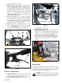
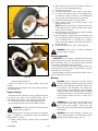
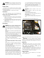
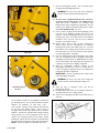
1
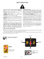
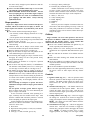
Hustler Model 50
22” Walk Behind
Greens Mower
Owner’s Manual
•••••••
Hustler Turf Equipment
•••••
P.O. Box 7000
•••
Hesston, Kansas
•
67062-2097
111132_0409
WARNING:
The engine exhaust from this product
contains chemicals known to the State
of California to cause cancer, birth
defects or other reproductive harm.
WARNING:
The
engine exhaust
fromARRESTER
this product
NOTICE OF
REQUIREMENT
OF SPARK
MUFFLER
chemicals
to theCalifornia
State Public Resources Code SecThis equipment may create sparkscontains
that can start
fires aroundknown
dry vegetation.
tion 4442.6 provides that it is unlawfulof
to California
use or operate
internalcancer,
combustion
engine on any forest-covered,
toancause
birth
brush-covered, or grass-covered land unless the engine is equipped with a spark arrester maintained in effective
working order. A spark arrester is a device
constructed
of nonflammable
defects
or other
reproductivematerials
harm.specifically for the purpose of
removing and retaining carbon and other flammable particles over 0.0232 of an inch in size from the exhaust flow of
an internal combustion engine that uses hydrocarbon fuels or which is qualified and rated by the United States Forest Service. Other states or federal areas may have similar laws. The Operator Should Contact Local Fire Agencies
For Laws or Regulations Relating to Fire Prevention Requirements. THIS EQUIPMENT DOES NOT HAVE A
SPARK ARRESTER AND YOUR SHOULD CONTACT YOUR AUTHORIZED HUSTLER DEALER FOR THE PURCHASE OF A SPARK ARRESTER.
IMPORTANT: This engine is not equipped with a spark arrester muffler. It is a violation of California Public Resource Code
Inspect
daily;this
replace
hours or as
needed. or grass-covered unimproved land. Other
Section spark
4442 toarrester
use or operate
engine every
on any500
forest-covered,
brush-covered,
states or federal areas may have similar laws.
TheEngine
Engine Owner’s
Owner’s Manual
information
regarding
the U.S.
Environmental
Protection
AgencyAgency
(EPA) and the
The
Manualprovides
provides
information
regarding
the U.S.
Environmental
Protection
California
Emission
Control
Regulation
of emission
systems,
and warranty.
(EPA)
and the
California
Emission
Control
Regulation
of maintenance
emission systems,
maintenance and warranty.
KeepEngine
Engine Owner’s
Owner’s Manual
the the
Engine
Owner’s
Manual
become
damaged
or illegible,
reKeep
Manualwith
withyour
yourunit.
unit.Should
Should
Engine
Owner’s
Manual
become
damaged
or illegiplace
immediately.
Replacements
may be ordered
per
the information
found in the Product
section
of the
ble,
replace
immediately.
Replacements
may be
ordered
per the information
found inInformation
the Product
Informaowner’s
manual.
tion
section
of the owner’s manual.
GENERAL INFORMATION
This manual applies to the following Hustler equipment
line:
Hustler Model 50 (22”)
Walk Behind Greens Mower
To the new owner
The purpose of this manual is to assist owners and operators in
maintaining and operating the Hustler Model 50 Greens Mower.
Please read it carefully; information and instructions furnished
can help you achieve years of dependable performance.
A separate Engine Owner’s Manual is included with your
owner’s packet which contains additional engine information
that will not be repeated in this manual. You are urged to read it
before attempting any operation or repair of the engine.
It is the owner’s responsibility to make certain that the
operators and mechanics read and understand this manual and
all decals before operating this machine. It is also the owner’s
responsibility to make certain that the operators and mechanics
are qualified and physically able individuals, properly trained in
the operation of this equipment. All operator and mechanics
must become familiar with the safe operation of the equipment,
operator controls and safety signs.
Never let children or untrained people operate or service the
equipment. Local regulations may restrict the age of the
operator.
IMPORTANT: For more detailed maintenance and adjustment information refer to the proper parts manual for your
machine. Refer to the “Product Literature” section of this manual for ordering information.
The owner/user can prevent and is responsible for accidents or
injuries occurring to themselves, other people or property.
Using this manual
General operation, adjustment and maintenance guidance is
outlined for both the experienced and novice Hustler user.
Operating conditions vary considerably and cannot all be
addressed individually. Through experience, however, operators
should find no difficulty in developing good operating skills
suitable to most conditions.
Directions used in this manual, for example RIGHT or LEFT,
refer to directions when seated on tractor facing forward, unless
otherwise stated.
111132_0409
1-1
Photographs and illustrations used were current at the time of
printing, but subsequent production changes may cause your
machine to vary slightly in detail. Hustler Turf Equipment
reserves the right to redesign and change the machine as deemed
necessary, without notification. If a change has been made to
your machine which is not reflected in this owner’s manual, or
the parts manual, see your Hustler dealer for current information
and parts.
Warranty registration
The Delivery and Warranty Registration form must be
completed and signed to validate your warranty protection. As
the new equipment owner, you are expected to see that the form
is completed and forwarded to Hustler Turf Equipment at time
of delivery.
Be sure to register the machine plus each attachment that
displays a model and serial identification number plate with
Hustler Turf Equipment.
IMPORTANT: Any unauthorized modification, alteration,
or use of non-approved attachments voids the warranty and
releases Hustler Turf Equipment from any liability arising from
subsequent use of this equipment.
Model and serial number
Tractor model and serial numbers are found on the serial
identification plate, located on the rear of the frame directly
below the engine.
These numbers are required on the Warranty Registration
form. They will also assure you of the correct service parts
when replacement becomes necessary.
Parts and service
Use original Hustler replacement parts only. These parts are
available through your local Hustler dealer. To obtain prompt,
efficient service, always provide the following information
when ordering parts:
1. Correct part description.
2. Correct model number.
3. Correct serial number.
All warranty repair and service must be handled through an
authorized Hustler dealer. Arrangements should be made
through your local service center.
1-2
111132_0409
HUSTLER MODEL 50 (22”) WALK BEHIND GREENS MOWER
THREE YEAR LIMITED WARRANTY
WHAT IS COVERED BY THIS WARRANTY
Hustler Turf Equipment, makes the following warranty to the
original purchaser only:
a. Three Year: Hustler Turf Equipment Model 50 (22”)
Walk Behind Greens Mowers are warranted for three
(3) years from date of delivery on all materials and
workmanship.
If the Purchaser discovers within this warranty period a
defect in materials or workmanship:
O He must promptly notify Hustler Turf Equipment, or
an authorized dealer, in writing of the defect. In no
event shall such notification be received by Hustler
Turf Equipment, or an authorized dealer later than
thirty-six (36) months from date of delivery.
O Within a reasonable time after such notification, Hustler Turf Equipment, will correct any defect in material or workmanship on the Hustler Turf Equipment,
by repairing or replacing part(s) with either new or
used replacement parts.
O Such repair, including parts and labor shall be at the
expense of Hustler Turf Equipment, and,
b. The engine is covered by a two (2) year limited
warranty, by the engine manufacturer, to the original
owner (commercial or residential) only, and,
WHO MUST PERFORM THE WARRANTY SERVICE
All warranty service will be performed by dealers authorized by
Hustler Turf Equipment. Service calls and/or transportation
expense of the product to and from the authorized dealer, for
warranty work, will be paid by the owner of the product. For
warranty service contact an authorized dealer or write Hustler
Turf Equipment, 200 South Ridge Road, Hesston, Kansas
67062, or call 1-620-327-4911.
WHAT IS NOT COVERED BY THIS WARRANTY
Hustler Turf Equipment, does not warranty:
O Some product, components or parts not manufactured
by Hustler Turf Equipment
O Repairs made by unauthorized persons
O Damage caused by use of the Hustler Turf Equipment
for purposes other than those for which it was
designed
O Damages caused by disasters such as fire, flood,
wind, and lightening
O Damages caused by neglect, abuse, abnormal use,
improper or unreasonable use, accident, negligence or
misuse
O Repairs or replacement resulting from the use of
unauthorized parts, accessories or attachments
O Repairs or replacement as the result if any alterations
or modifications, in the determination of Hustler Turf
Equipment, which adversely affects the operation,
performance or durability of the equipment.
O Hustler Turf Equipment which has the serial number
removed or made illegible
O Depreciation or damage caused by normal wear, lack
of reasonable and proper maintenance, failure to fol111251_0409
1-3
low the product’s owner’s manual operating, maintenance and adjustment instructions or other
operational instructions provided by Hustler Turf
Equipment.
O Normal maintenance parts and service including, but
not limited to, filters, fuel, lubricants, tune-up parts,
belts, reels, bedknife, reel sharpening, bearings, brake
adjustments
O Repairs necessary due to improper fuel, contaminates
in the fuel system, or failure to properly prepare the
fuel system prior to any period of non-use over three
months
DISCLAIMER OF WARRANTY
The foregoing warranties are in lieu of all other warranties,
expressed or implied, including but not limited to the
implied warranties of merchantability and fitness for a particular purpose. However, if the Hustler Turf Equipment is
purchased as a consumer product, any implied warranty of
merchantability or fitness for a particular purpose is limited
to the duration of this limited warranty. Some states do not
allow limitations on how long an implied warranty lasts, so
the above limitation may not apply to you. This warranty
gives you specific legal rights, and you may also have other
rights which vary from state to state.
LIMITATION OF REMEDIES
In no case shall Hustler Turf Equipment, be liable for any special, incidental, or consequential damages based upon breach of
warranty, breach of contract, negligence, strict liability in tort,
or any other legal theory.
Such damages include, but are not limited to:
O Loss of profits
O Loss of savings or revenue
O Loss of use of Hustler Turf Equipment or any associated equipment
O Cost of capital
O Cost of any substitute equipment, facilities, services
or downtime
O The claims of third parties including customers, and
injury to property
Some states do not allow the exclusion or limitation of incidental or consequential damages, so the above limitation or exclusion may not apply to you.
TIME LIMIT
Any action for breach of warranty must be commenced within
twenty-five (25) months following delivery of the goods in a
residential application. Any action for breach of warranty
must be commenced within 120 days following delivery of the
goods in a rental application.
NO OTHER WARRANTIES
Unless modified in writing, signed by both parties, and
approved by the President of Hustler Turf Equipment, this
agreement is understood to be the complete and exclusive agreement between the parties, superseding all prior agreements, oral
or written, and all other communications between the parties
relating to the subject matter of this agreement. No employee of
Hustler Turf Equipment, or any other party is authorized to
make any warranty in addition to those made in this agreement.
ALLOCATION OF RISKS
This agreement allocates the risks of product failure between
Hustler Turf Equipment, and the purchaser. This allocation is
recognized by both parties and is reflected in the price of the
goods.
OWNER'S RESPONSIBILITY
You must maintain your Hustler Turf Consumer Product following the maintenance procedures described in your owner's manual. Such routine maintenance, whether performed by a dealer
or by you, is at your expense.
This machine like any other powered equipment is potentially dangerous unless properly operated. Any operator
must be cautious and keep safety in mind at all times. Any
1-4
operator, prior to using the Hustler Turf Equipment, should thoroughly familiarize himself with the owner's manual regarding
operation and safety of the machine, as well as all safety warnings on the machine itself.
WARRANTY REGISTRATION
1. Dealers must register the unit on-line at
www.Hustlerdealer.com or by filling out the Warranty
registration form, provided in the owner’s packet. If
using the Warranty registration form it MUST be
completed and signed by the authorized dealer and
original purchaser.
2. For validation, the completed Warranty registration form
MUST be forwarded to Hustler Turf Equipment, within
ten (10) days following date of purchase.
3. The date of purchase constitutes delivery.
111251_0409
SAFETY PRECAUTIONS
This safety alert symbol is used to call attention to a message
intended to provide a reasonable degree of PERSONAL
SAFETY for operators and other persons during the normal
operation and servicing of this equipment.
DANGER – denotes immediate hazards which WILL result
in severe personal injury or death.
WARNING – denotes a hazard or unsafe practice which
COULD result in severe personal injury or death.
This manual uses two other words to highlight information.
IMPORTANT calls attention to special mechanical information
and NOTE: emphasizes general information worthy of special
attention.
All operators should read this manual, or be instructed about
safe operating and maintenance procedures. This is the owner’s
responsibility.
Improper use or maintenance by the operator or owner
can result in injury. To reduce the potential for injury,
comply with these safety instructions and always pay
attention to the safety alert V symbol, which means
DANGER or WARNING - “personal safety instructions.”
Failure to comply with the instructions may result in
personal injury or death.
Incorrect usage of this machine may result in severe
injury. Personnel operating and maintaining it should be
trained in the proper use and should read the manuals
completely and thoroughly before attempting to set-up,
operate, adjust, or service this machine.
It is the owner’s responsibility to make certain that the
operators and mechanics read and understand this manual and
all decals before operating this machine. It is also the owner’s
responsibility to make certain that the operators and mechanics
are qualified and physically able individuals, properly trained in
the operation of this equipment. All operators and mechanics
must become familiar with the safe operation of the equipment,
operator controls and safety signs. Local regulations may
restrict the age of the operator.
The owner should also ensure that the operator/mechanic
know that they are responsible for their own safety as well as the
safety of other persons within the vicinity. Remember, the
operator is responsible for accidents or hazards occurring to
other people or their property.
Safety and Instruction Decals
V Specific safety warning decals are located on the equipment near the immediate areas of potential hazards. These decals should
not be removed or obliterated. Replace them if they become non-readable.
The following illustrations show the various safety decals that are located on the machine. A brief explanation is shown to help the
operator understand the meanings of these decals.
Disengage
Read Owner’s Manual and decals before
attempting to operate this machine.
Traction
drive
engaged
Cutting reel
engaged
WARNING:
Hot surface!
602060
602058
Engage
• Avoid skin contact
with hot surface
602057
727453CE
DANGER:
Rotating pulleys and belts!
111132_0409
2-1
• Keep hands, feet and clothing away.
• Keep shields or covers in
place while machine is in
operation.
DANGER:
Rotating reel knife!
Cutting hazard!
WARNING:
Thrown
objects!
WARNING:
Falling!
STOP
STOP
602058
Read Operator’s Manual
before attempting to
operate this machine.
Read Operator’s Manual
before servicing this machine.
• Disconnect spark plug
before servicing.
• Before and while backing,
• Keep hands, feet and
• Always maintain a
safe distance from
people and pets
when mowing.
•
clothing away.
Keep shields and covers
in place while machine is
in operation.
look behind and down for
small children and obstacles.
• Keep grass
catcher in place
while machine is
in operation
• Stop engine and
• Traverse across slopes.
• Avoid driving the machine
straight up and down slopes.
mower reel before
servicing this
machine.
A
C
G
B
602059
D
E
F
A.
B.
C.
D.
Fast
Slow
Park brake
Read Operator’s Manual before attempting to operate this
machine.
E. Read Operator’s Manual before attempting to service this
machine. Disconnect spark plug before servicing
F. Wear ear protection, eye protection and safety shoes when
operating this equipment.
G. Service brake
2-2
111132_0409
WARNING:
Fire!
• Do not smoke while refueling.
• Do not remove the fuel tank cap or fill with engine running or
while the engine is hot.
• Allow engine to cool before storing machine inside a building.
• Store away from open flame or spark if there is fuel in tank.
• Clean up any gasoline spills.
Read owner’s manual before
operating
WARNING:
Carbon monoxide
poisoning
• Never run the engine in an enclosed area
unless exhaust is vented to the outside.
Exhaust gases contain carbon monoxide
which is an odorless and deadly poison.
WARNING
FAILURE TO FOLLOW SAFE OPERATING MAY RESULT IN INJURY.
1. Read operator’s manual.
Operation of this equipment may create sparks
that can start fires around dry vegetation. A spark
arrestor may be required. The operator should
contact local fire agencies for laws or regulations
relating to fire prevention requirements.
601908
2. Keep guards and safety devices in place and working.
3. Wait for all movement to stop before servicing machine.
4. Keep hands and clothing away from rotating blades and belts.
WARNING
AVOID INJURY FROM ROTATING BLADES
1. Keep hands and feet away from rotating blades.
2. Shut off engine before servicing or lubricating.
111132_0409
2-3
2-4
111132_0409
SLOPE GUIDE
Use this diagram when determining the degree of slope to be mowed.
E (15o)
Slope Guide Lines
D (10o)
Line B
C (5o)
Line A
1.
2.
3.
4.
Hold this sheet of paper in front of you. Make sure that Line A is horizontal.
Align Line B with a vertical surface such as pole, tree or building.
Fold the paper along the slope guide lines (C, D or E).
Align the closest slope guide line with the ground slope. This will give you a close estimation of the ground slope
111132_0409
2-5
2-6
111132_0409
OPERATION
Safe Operating Practices
This product is capable of amputating hands and feet and
throwing objects. Always follow all safety instructions to avoid
serious injury or death.
Operation
V Never leave a running machine unattended. Always disengage transmission drive, cutting reel drive, and stop
engine when leaving the unit. Wait for engine and all
moving parts to come to a complete stop before leaving
the machine for any reason.
V Do not change the engine governor setting or overspeed
the engine. Operating the engine at excessive speed may
increase the hazard of personal injury.
V Always keep safety shields and covers in place, except
for servicing.
V Always maintain a safe distance from people and pets
when mowing. Always stop machine if someone enters
the area.
V Always operate machine in daylight or with adequate
working lights.
V Follow daily and weekly checklists, making sure all hardware is tightened.
V Always observe traffic laws while driving machine from
one location to another. Watch for traffic when operating
near or crossing roadways.
V Use care when approaching blind corners, shrubs, trees or
other objects that may obscure vision.
V Using this machine demands attention. To prevent loss of
control:
• Do not drive close to sand traps, ditches, creeks, or
other hazards.
• Reduce speed when making sharp turns. Avoid sudden
stops and starts.
• When near or crossing roads, always yield the right-ofway.
• Apply, the service brakes when going downhill to keep
forward speed slow and to maintain control on the
machine.
V Always keep engine and machine clean, removing accumulated dirt, trash and other material from machine.
Clean up oil or fuel spillage. Allow machine to cool
before storing.
V Inspect area to be mowed for hazards such as rocks,
metal objects and other debris which may be thrown or
entangled by cutting reel. Remove these objects before
mowing.
V Always be alert for hazards such as rocks, metal objects
and other debris which may be thrown or entangled by
cutting reel. Watch out for holes or deep depressions.
V Always wear adequate ear protection, such as earplugs,
when operating this equipment as prolonged exposure to
uncomfortable or loud noises can cause impairment or
loss of hearing. Do not wear radios or music headphones
while operating the machinery. Safe operation requires
your full attention.
111132_0409
3-1
V Do not operate the equipment while wearing sandals, tennis shoes, sneakers, shorts or any type of loose fitting
clothing. Do not use a towel as a headband or neck wrap
and do not hang towel from the waist. Long hair, loose
clothing or jewelry may get tangled in moving parts.
Always wear long pants, safety glasses, ear protection
and safety shoes when operating this machine.
V Always wear safety goggles or safety glasses with side
shields when operating the mower.
V Always inspect machine for damage after striking a foreign object. If damage is found, repair machine immediately. Be sure to stop on level ground, always disengage
transmission drive, cutting reel drive, stop engine, and
remove ignition key when leaving the unit. Wait for
engine and all moving parts to come to a complete stop
before leaving the machine for any reason.
V Always be aware of what is behind the machine before
backing up.
V Never operate a poorly maintained machine.
V Make sure all fasteners and mounting hardware are
tightly assembled to basket.
V Inspect grass catcher daily for wear or cracks and make
sure it is mounting properly and in good condition.
V Do not operate without entire exhaust system in place
and in proper working condition.
V Never attempt high speed maneuvering, especially in
crowded or congested areas.
V Never allow persons to operate this machine without
proper instruction or allow children to operate machine.
Allow only responsible adults who are familiar with
these instructions to operate this machine.
V Never put hands or feet under any part of the machine
while it is running.
V Never carry passengers. They can be struck by foreign
objects or fall off machine and be seriously injured. They
can interfere with the safe operation of the machine.
V Never direct discharge of material from mower towards
bystanders. Do not operate the mower without grass
catcher in place.
V Always disengage the cutting reel and wait for it to stop
before crossing gravel drives, walks or roads..
V Always keep clear of the cutting reel during operation.
V Slow down and use caution when making turns and
crossing roads and sidewalks. Stop reel if not mowing.
V Stop the engine before removing the grass catcher. Turn
off the engine and be sure the cutting reel has stopped
before cleaning. Never use your hand to clean the cutting reel area!
V Do not operate the machine if you are fatigued, sick or
while under the influence of alcohol or drugs, you are
pregnant or under 18 years old. Local regulations may
restrict the age of the operator.
V Exercise caution when loading or unloading the machine
onto a trailer or truck.
V Data indicates that operators, age 60 years and above, are
involved in a large percentage of mower-related injuries.
These operators should evaluate their ability to operate
the mower safely enough to protect themselves and others from serious injury.
V Never cover the machine with a tarp or cover of some
type until the engine and muffler have cooled.
V Clean flammable material from machine. Prevent
fires by keeping the top of the unit, engine compartment and exhaust area clean of accumulated trash,
grass clippings, and other debris. Always clean up
spilled fuel and oil.
Slope operation
Slopes are a major factor in loss-of-control and tip-over
accidents, which can result in severe injury or death. All
slopes require extra caution. If you feel uneasy on it; do not
mow it.
V Use extreme caution when operating on slopes.
• Be extremely careful changing directions on a slope.
Slow down.
• Do not operate where the machine could slip or tip.
V Always be sure of your footing. Keep a firm hold on the
handle and walk - never run.
V Block or chock the machine when parked on a slope or
when trailering.
V Watch for holes, ruts or bumps. Uneven terrain could
overturn the machine. Tall grass can hide obstacles.
V Remove obstacles such as rocks, tree limbs, etc.
V Keep all movement on slopes slow and gradual. Do not
make sudden changes in speed or direction.
V Avoid starting and stopping on a slope. If traction is lost,
disengage the cutting reel drive and proceed slowly
straight down the slope.
V Never operate the machine on a slope fro a position
below the mower!
V Do not mow near drop-offs, ditches, or embankments.
The machine could suddenly turn over if a wheel goes
over the edge of a cliff or ditch, or if an edge caves in.
V The Model 50 Greens Mower is capable of driving on
slopes up to 15 degrees, when the transport wheels are
attached. Be aware of any conditions that may cause the
transport wheels to lose traction resulting in possible loss
of control of the machine. Operators should not operate
on a slope until they are thoroughly familiar with the
equipment.
Do not attempt to transport or operate the mower
without the transport wheel on slopes greater than 10
degrees.
Do not operate on slopes greater than 15 degrees.
Refer to Slope Guide, page 2-5, when determining the
degree of slope to be mowed.
If loss of traction is detected, when operating on a
slope, cautiously drive the machine off the slope. Wait
until the condition that caused the problem is resolved
before attempting to operate on the slope again.
Terrain conditions can affect traction resulting in possible loss of control of the machine. Some of the conditions to be aware of are:
1. Wet terrain
2. Depressions in the ground; i.e. holes, ruts, washouts
3. Mounds of dirt
4. Soil type; i.e. sand, loose dirt, gravel, clay
3-2
5. Grass type, density, and height
6. Extremely dry conditions of grass
Another consideration to safe mowing on slopes is to
be aware of what is located at the bottom of the slope.
Extreme caution should be used when there is a hazard
located at the bottom of the slope. Some examples are:
1. Water; i.e. lake, river
2. Cliffs, retaining walls
3. Roads, highways
4. Buildings
5. Rocks
These are just a few examples of situations when caution must be used when operating on a slope. There are
many other possibilities too numerous to mention. Just
remember to always exercise extreme caution when operating on any slope.
Children
Tragic accidents can occur if the operator is not alert to
the presence of children. Children are often attracted to the
machine and the mowing activity. Never assume that
children will remain where you last saw them.
V Never leave machine unattended with ignition key in
switch, especially with children present.
V Keep children out of the mowing area and under the
watchful care of a responsible adult other than the operator.
V Be alert and turn the machine off if children enter the
area.
V Before and while backing, look behind and down for
small children.
V Never carry children, even with the cutting reel off. They
may fall off and be seriously injured or interfere with safe
machine operation.
V Never allow children to operate the machine.
V Use care when approaching blind corners, shrubs, trees,
the end of a fence or other objects that may obscure
vision.
Controls
A. Ignition switch (Fig. 3-1) — This two position switch
allows the operator to shut the engine off at the operating
position. The RUN position allows the engine to be
started and to run. The OFF position will shut off the
engine.
B. Throttle control (Fig. 3-1) — The throttle control lever
is mounted off the RH operator handle. This lever
controls the engine speed via a cable. Push the lever
forward to increase engine speed and pull it rearward to
decrease engine speed.
C. Cutting reel drive lever (Fig. 3-1) — This lever engages
the cutting reel. Push the lever forward to engage the
cutting reel and pull it back to disengage the cutting reel.
NOTE: The cutting reel will rotate ONLY when the
traction drive is engaged.
D. Traction drive lever (Fig. 3-1) — This lever engages the
traction drive. Push the lever forward to engage the
traction drive, and pull it back to disengage the traction
drive. NOTE: If cutting reel drive lever is in the
engaged position, the cutting reel will begin rotating
111132_0409
when the traction drive is engaged.
E. Brake lever (Fig. 3-1 & Fig. 3-2) — The brake lever is
mounted off the LH operator handle. This brake has two
levers. The longer lever is pulled to engage the brake.
To set the park brake, pull this long lever back toward the
handlebar until the park brake lever snaps into the locked
position. Release the long brake lever, and the park
brake is set. To release the park brake, pull on the
shorter park brake lever and the long brake lever
returns to the released position
F. Choke control (Fig. 3-3) — The choke is controlled
directly on the engine. As the decal indicates, the choke
is on when the lever is pushed to the forward direction of
the machine, and off when the lever is pulled to the rear.
Choke should only be used when starting the engine, and
shall remain off when in normal operation.
G. Fuel valve (Fig. 3-3) — Push fuel valve lever forward to
open fuel valve and push lever rearward to shut fuel
valve off. IMPORTANT: Fuel valve should be shut off
when engine is not running and machine is stopped.
C
A
D
B
G Fuel valve shown in “OFF” position
F Choke shown in “OFF” position
Fig. 3-3
used and shall remain unplugged.
C. Engine coil kill wire (Fig. 3-4)
D. Ignition switch wire (Fig. 3-4) — This single green wire
connects to the ignition switch located at the operator
handlebars. It is to remain plugged into the female bullet
connector from engine coil kill wire at all times.
E. Braided wire loom - optional light power (Fig. 3-4) —
These wires provide power to the optional light kit.
Leave bundled with the tape in place if light kit is not
installed.
E
B
Fig. 3-1
C
A
E
E
D
Fig. 3-4
Grass catcher
Park brake lever
When attaching the grass catcher make sure that the catcher’s
mounting pins are seated firmly in place on the mower. Make
sure that it is down in the positioning slots as far as it will go and
is not sitting at an angle. Fig. 3-5 & Fig. 3-6
Fig. 3-2
Electrical - Engine wiring
A. Engine switch (Fig. 3-4) — There is an “ON - OFF”
switch located on the front of the engine. This switch is
not used and shall remain in the off position.
B. Wire lead - engine switch (Fig. 3-4) — This wire is not
111132_0409
3-3
WARNING: Attach the grass catcher prior to starting
the engine to prevent injury. Grass catcher should be
attached to machine at all times when in operation!
on the stand.
2. Press down on the stand and push the machine forward.
The stand will release. Do not release pressure from
the stand until the stand is fully raised to prevent
injury to the operator’s foot or leg.
Stand in down position
Stand in up position
Grass catcher
Fig. 3-7
Fig. 3-5
Transport wheels (optional)
Catcher pin
Fig. 3-6
Stand setting
The unit is equipped with a stand to raise the unit’s drive
roller off the ground to allow the unit to be worked on or the
optional transport wheels to be installed.
To raise the machine (Fig. 3-7):
1. Park the unit on a flat, level surface, shut off engine and
set the brakes.
2. Place both hands on the machine’s handles and one foot
on the stand.
3. Push the stand down, with one foot, until it contacts the
ground.
NOTE: Make sure to keep pressure on the stand as it can
spring back and hit the operator’s foot or leg.
4. While holding the stand in place, pull back on the handles
until the machine pivots up and back onto the stand. The
machine will then be supported by the stand and the front
roller.
5. Place a block in front of the front roller to prevent the
machine from moving forward and releasing the stand.
To lower the machine (Fig. 3-7):
1. Place both hands on the machine’s handles and one foot
3-4
A transport wheel option is available for the Model 50. These
wheels are used when transporting the unit from one location to
another or when loading on a trailer or truck.
To attach the wheels use the following procedure:
1. Raise the unit using the stand setting procedure outlined
elsewhere in this manual.
2. Hold the transport wheel with one hand while rotating
clockwise on the locking lever with the other hand.
Fig. 3-8
3. Align the three holes in the wheel with the three bolt
heads on the axle hub. Slide the wheel onto the shaft and
release the locking lever. It should lock in place on the
shaft. Fig. 3-9
4. Repeat for other side.
5. Lower the machine per the stand setting procedure
outlined elsewhere in this manual.
To remove the wheels use the following procedure:
1. Raise the unit using the stand setting procedure outlined
earlier.
2. Hold the transport wheel with one hand while rotating
clockwise on the locking lever with the other hand.
3. Slide the wheel off the shaft and release the locking lever.
4. Repeat for other side.
5. Lower the machine per the stand setting procedure
outlined elsewhere in this manual.
Safety Interlock circuit operation
The safety interlock system on this machine does not allow
the engine to be started when the traction drive is engaged. This
system must be checked daily to make sure it is working
properly.
1. Park the machine on level ground and pull it up on the
stand to keep the traction drive drum (and wheels if
equipped) raised off the ground.
2. Make sure the park brake is disengaged.
3. Engage the traction drive lever. Set the ignition switch to
the run position.
4. Try to start the engine. The engine should NOT start. If
the engine starts, then the safety interlock switch needs to
be checked to make sure it is adjusted properly or the
111132_0409
2. Make sure the traction drive lever and the cutting reel
drive lever are in the disengaged position.
3. Attach the grass catcher.
4. Turn the fuel shutoff valve to the “open”or “on” position.
5. Use choke when engine is cold, or if warm engine fails to
start within 5 seconds of cranking. Avoid flooding and
operate engine without choking as soon as possible.
6. Set throttle at approximately 1/2 open position.
7. Rotate ignition switch to the “RUN” position. Pull
engine recoil start rope.
NOTE: Pull the recoil start rope to about 4/5 of the maximum length of the rope. Allow the starter rope to return
slowly to the recoil housing.
8. Allow the engine to idle a few minutes before advancing
the throttle and operating the unit.
9. Before stopping the engine, place the traction drive lever
in the disengaged position, disengage the cutting reel
drive, and throttle back to 1/2 throttle for a couple of
minutes; then rotate ignition switch counter-clockwise to
the OFF position.
10. Turn the fuel shutoff valve to the “closed” position.
Locking lever
Transport wheel
Fig. 3-8
Transport wheel
WARNING: Never leave the machine unattended
when the engine is running.
General operation
Bolt
heads
Holes
IMPORTANT: Do not operate or transport the mower using
the drive drum on any surfaces other than the turf to be mowed.
When transporting, always use the transport wheels (optional)
or a transport vehicle/trailer to move the mower.
Keep cutting reel knives and bedknife sharp and make sure
the clearance between the cutting reel and bedknife is properly
adjusted prior to each mowing.
Check the height of cut before each mowing to make sure it is
properly adjusted and set evenly.
Fig. 3-9
Mowing
problem identified and fixed.
Contact your dealer if you cannot identify and fix the
problem.
Do not operate the machine if the safety interlock circuit is
not working properly.
Engine starting
The Model 50 safety interlock system is designed to protect
the operator and others from accidental injury due to
unintentional engine starting. The engine will not start until:
A. Traction drive lever is in the “Disengaged” position.
B. The ignition switch is turned to the “RUN” position.
WARNING: The safety interlock system must not be
disconnected or bypassed.
The following steps are the correct procedures for starting the
engine. If difficulty is encountered, contact the Authorized
Hustler Dealer in your area.
1. Before starting mower, perform daily pre-operation
checking.
111132_0409
3-5
DANGER: Prior to operating the unit the operator
should be thoroughly familiar with the proper use and
operation of the equipment, should have read the manual completely and thoroughly, and should have
attempted slow moving maneuvers to become familiar
with the operation of the equipment before attempting
normal speed operation. An untrained and inexperienced operator should not mow on slopes or on
uneven terrain.
WARNING: Do not operate the equipment while
wearing sandals, tennis shoes, sneakers, shorts or any
type of loose fitting clothing. Always wear long
pants, safety glasses and safety shoes when operating
this machine.
WARNING: Never direct discharge of material from
mower towards bystanders. Do not operate the mower
without the grass catcher in place. Fig. 3-5
WARNING: Make sure there are no bystanders close
to the unit, especially in front of the machine, when
the traction drive lever is engaged. When the traction
drive lever is engaged the machine will immediately
move forward.
WARNING: Attach the grass catcher prior to starting
the engine to prevent injury. Do not operate the unit
without the grass catcher.
IMPORTANT: Before mowing, check to make sure the cutting reel knives and bedknife are sharp and clearance between
the reel and bedknife is properly adjusted. Do not operate the
unit with the cutting reel engaged for a long period of time when
not cutting grass - this can damage the reel and bedknife. Grass
provides a natural lubrication of the reel knives and bedknife.
1. Always check area to be mowed and remove any debris,
rocks or other foreign objects. Take special note of
locations of hazards or potential objects that could
damage the mower or cause potential safety issues.
2. Check mower over to make sure it is operating properly,
the grass catcher is properly attached and all the guards
and shields are properly installed.
3. Transport the mower to the collar of the green. Remove
the transport wheel (if attached).
4. To begin mowing, the throttle should be set at a speed
where the operator feels comfortable operating the unit.
Transport the mower to the collar of the green and
position it in the direction to be mowed. Engage the
cutting reel drive lever, raise the cutting reel by pushing
the handles down and engage the traction drive lever. Set
the cutting reel down at the proper location to start
mowing and mow in a straight line.
5. There are marks located on each side of the grass catcher
to indicate the mowing width. Align one of the marks
with the outside edge of the uncut grass and mow using
the mark as a guide. Fig. 3-10
6. To stop mowing at the end of the green when
approaching the collar, disengage the cutting reel drive
lever, drive off the green and disengage the traction drive
lever.
7. To turn the unit at the end of a row, when approaching the
end of the row, push down on the handles to raise the
cutting reel and turn the mower by pivoting it on the
traction drum. When the turn has been completed, locate
the last row mowed and position the mower straight with
the last row. Set the cutting reel down at the proper
location to begin mowing the next row.
8. When the grass catcher becomes full, stop the mower and
turn off the engine. Remove the grass catcher and dispose
of the grass clippings in an appropriate location. Treat the
grass clippings as combustible waste, keeping it away
from any possibility of a fire hazard.
Transporting
Transporting the Model 50, using the optional transport
wheels, under its own power, requires considerable skill.
Practice maneuvering in an open area before attempting to drive
it from one location to another.
3-6
Marks
Fig. 3-10
WARNING: Make sure there are no bystanders close
to the unit, especially in front of the machine, when
the traction drive lever is engaged. When the traction
drive lever is engaged the machine will immediately
move forward.
WARNING: Do not drive the machine, without transport wheels, when it is on anything but turf if the
transport wheels are not installed. The rear roller and
the roller shaft may become damaged resulting in
abnormal rotation.
1. Set the throttle to the “slow” position.
2. Grip the operator handle with one hand and engage the
traction drive lever slowly.
3. As soon as the traction drive is engaged the machine will
move forward. Grip the operator handles securely with
both hands.
4. To stop the machine; disengage the traction drive lever
then engage the brake.
Transporting the Model 50, on a vehicle, requires two or
more people to load and unload the machine onto the transport
vehicle.
WARNING: Make sure there are no bystanders close
to the unit when loading or unloading to prevent
injury.
WARNING: When loading or unloading onto a transport vehicle the engine must be shutoff. The unit must
not be loaded or unloaded using it’s own power. It
should be maneuvered manually.
WARNING: Do not attempt to grab the unit in the
area near the cutting reel or bedknife when lifting the
unit by hand. The reel and bedknife are very sharp
and can cause injury.
WARNING: Take care that the machine does not fall
from the loading ramp or off of the transport vehicle.
111132_0409
IMPORTANT: Attach the transport tires before the machine
is loaded or unloaded onto a transport vehicle. Otherwise, the
rear roller and it’s shaft may become damaged.
To load or unload on a transport vehicle use the following
procedure:
1. Make sure the traction drive lever and the cutting reel
drive lever are in the disengaged position.
2. The engine is turned off and the fuel shutoff valve is in
the “closed” position.
111132_0409
3-7
3. Use a full width ramp to load/unload the machine.
4. With one person controlling the brake lever, both people
should carefully pull the machine up the ramp and onto
the vehicle.
IMPORTANT: Pull the machine, do not push it, up the
ramp.
5. Secure the machine to the transporting vehicle.
3-8
111132_0409
MAINTENANCE & ADJUSTMENTS
Safe Servicing Practices
This product is capable of amputating hands and feet and
throwing objects. Always follow all safety instructions to avoid
serious injury or death.
V
Service
V
V Unless specifically required, DO NOT have engine running when servicing or making adjustments to mower.
Park the machine on level ground. Always disengage
traction drive, cutting reel drive, stop engine and disconnect spark plug wire before doing any maintenance. Wait
for engine and all moving parts to come to a complete
stop before adjusting, cleaning or repairing. Repairs or
maintenance requiring engine power should be performed by trained maintenance personnel only. To prevent carbon monoxide poisoning, be sure proper
ventilation is available when engine must be operated in
an enclosed area. Read and observe safety warnings in
front of manual.
V Before working on any part of this machine, make certain
engine cannot be accidentally started. Repairs or maintenance requiring engine power should be performed by
trained personnel only.
V Except when changing or checking belt, always keep belt
covers on mower for safety as well as cleanliness.
V Keep your machine clean and remove any deposits of
trash and clippings, which can cause engine fires and
excessive belt wear. Clean up oil or fuel spillage. Allow
machine to cool before storing.
V Clean flammable material from machine. Prevent
fires by keeping the top of the unit, engine compartment and exhaust area clean of accumulated trash,
grass clippings, and other debris. Always clean up
spilled fuel and oil.
V Always wear adequate eye protection when servicing the
unit and removing accumulated debris.
V Use extra caution when handling gasoline and other
fuels. They are flammable and vapors are explosive.
V Never attempt to start engine when there is a strong odor
of gasoline fumes present. Locate and correct cause.
V Never remove fuel cap or refuel machine while engine is
running; never refuel near an open flame or near devices
which can create a spark. Allow the engine to cool down
before refueling. Refuel outdoors. Never refuel or drain
the fuel from the machine indoors.
V Never run the engine in an enclosed area unless exhaust
is vented to the outside. Exhaust gases contain carbon
monoxide which is odorless and deadly poison.
V Never attempt to make any adjustments or repairs to the
traction drive system or reel while the engine is running
or cutting reel drive is engaged. Reel knife cannot be
seen and are located very close to the cutting reel housing. Fingers and toes can be cut off instantly. Repairs or
111132_0409
4-1
V
V
V
V
V
V
V
maintenance requiring engine power should be performed by trained maintenance personnel only.
Be careful during adjustment of the machine to prevent
entrapment of the fingers between reel and fixed parts of
the machine.
Never work under the machine or attachment unless it is
safely supported. Make certain machine is secure.
Do not touch hot parts of machine. Be careful of hot
muffler.
Keep nuts and bolts tight, especially the bedknife attaching bolts. Keep equipment in good working condition.
Never tamper with safety devices. Check their proper
operation regularly.
Stop the engine before removing the grass catcher. Turn
off the engine and be sure the cutting reel has stopped
before cleaning.
Use caution when cleaning around cutting unit. Wear
gloves and use the proper tools to clean debris from the
reel area.
Grass collection system components are subject to wear,
damage and deterioration, which could expose moving
parts or allow objects to be thrown. Frequently check
components and replace with manufacturer’s recommended parts, when necessary.
Use only genuine Hustler replacement parts to ensure that
original standards are maintained
Introduction
WARNING: Before working on the mower, make certain engine cannot be accidentally started. Shut engine
off and disconnect spark plug wire. Repairs or maintenance requiring engine power should be performed by
trained personnel only.
WARNING: Exercise caution when working around
the cutting reel, the reel blades and bedknife are
extremely sharp. Wearing gloves is advisable when
working around or with the blades.
WARNING: Except when changing or checking belt,
always keep belt covers on mower for safety as well
as cleanliness.
Regular maintenance is the best prevention for costly
downtime or expensive, premature repair. The following pages
contain suggested maintenance information and schedules
which the operator should follow on a routine basis. For more
detailed information order the correct parts manual for your
unit. Refer to the Product Literature section of this manual.
Remain alert for unusual noises, they could be signaling a
problem. Visually inspect the machine for any abnormal wear
or damage. A good time to detect potential problems is while
performing scheduled maintenance service. Correcting the
problem as quickly as possible is the best insurance.
WARNING: Keep your machine clean and remove
any deposits of trash and clippings, which can cause
engine fires, poor cut quality and excessive belt wear.
Torque values
For all torques refer to the Model 50 parts manual for standard
torque chart. See the Product Literature section of this manual
for ordering information.
For engine torque values, see engine owner’s manual.
Lubrication
Use a SAE multi-purpose grease when lubricating this
machine. Refer to the Maintenance Locator Chart, found
elsewhere in this manual, for all lubrication points. .
To lubricate these points:
1. Wipe away all old grease and dirt from the lubrication
fittings to prevent dirt or foreign material from entering
as new grease is applied.
2. Use a high pressure grease gun to force in the new grease.
Apply pressure until clean grease oozes from each
lubrication point.
3. Wipe away any excess grease.
zle. If a gasoline dispenser nozzle must be used, keep
the nozzle in contact with the rim of the fuel tank or
container opening at all times until fueling is complete. Do not use a nozzle lock-open device.
Read and observe safety precautions elsewhere in this
manual.
WARNING: Gasoline is harmful or fatal if swallowed.
Long-term exposure to vapors can cause serious
injury and illness.
Avoid prolonged breathing of vapors.
Keep face away from nozzle and gas tank or fuel container opening.
Keep gas away from eyes and skin.
If fuel is spilled on clothing, change clothing immediately.
The fuel tank is located on top of the engine. Fig. 4-1
Fuel tank
Air filter
Fuel system
DANGER: Observe usual fuel handling precautions:
Do not smoke while refueling. Extinguish all cigarettes, cigars, pipes and other sources of ignition.
Do not remove fuel cap or fill tank with engine running or while engine is hot. Clean up any gasoline
spills.
Allow engine to cool before storing machine inside a
building.
Keep fuel away from open flame or spark and store
machine away from open flame or spark or pilot light
such as on a water heater or other appliances.
Use extreme care when handling gasoline and other
fuels. They are extremely flammable and vapors are
explosive. A fire or explosion from gasoline can burn
you and others and can damage property.
Never refuel or drain the fuel from the machine
indoors.
Never attempt to start engine when there is a strong
odor of gasoline fumes present. Locate and correct
cause.
Store gasoline in an approved container and keep it
out of the reach of children. Never buy more than a
30 day supply of gasoline.
Always place gasoline containers on the ground away
from your vehicle before filling.
Do not fill gasoline containers inside a vehicle or on a
truck or trailer bed with interior carpets or plastic
truck bed liners. Always place gasoline containers on
the ground away from your vehicle before filling.
When practical, remove gas-powered equipment from
the truck or trailer and refuel the equipment with its
wheels on the ground. If this is not possible, then
refuel such equipment on the truck or trailer using a
portable container and not a gasoline dispenser noz4-2
Fig. 4-1
Use regular unleaded gasoline with an octane rating of 87 or
higher.
IMPORTANT: Never use methanol, gasoline containing
methanol, or gasohol containing more than 10% ethanol because
the fuel system components could be damaged. Do not mix oil
with gasoline.
Engine oil
Check engine oil daily and after every 4 hours of operation.
The machine must be setting level when checking oil. Refer to
engine manual and maintenance schedule for oil
recommendation and capacities. Fig. 4-2
Change the engine oil after the first 5 hours of operation, per
the engine manufacturer’s recommendations after that. If
machine is being operated in extremely dirty conditions, then it
is recommended oil be changed more frequently.
Engine air filter
Perform engine air filter maintenance per the engine’s
owner’s manual. Fig. 4-1
111132_0409
Engine oil
dipstick and fill
Main drive
belts
Fig. 4-3
Fig. 4-2
General engine maintenance
Detailed instructions and recommendations for break-in and
regular maintenance are specified in the Engine Owner’s
manual. Please refer to this manual for engine servicing,
lubricating oil levels with quality and viscosity
recommendations, bolt torques, etc. The engine warranty is
backed by the manufacturer. Special attention should be paid to
applicable data which will not be duplicated here.
Reel drive belt
Belts
Inspect belts frequently for wear and serviceability. (Fig. 4-3
& Fig. 4-4) Replace a belt that shows signs of severe cuts, tears,
separation, weather checking and cracking, or burns caused by
slipping. Slight raveling of belt covering does not indicate
failure, trim ravelings with a sharp knife.
Inspect the belt pulley grooves and flanges for wear. A new
belt, or one in good condition, should never run against the
bottom of the groove. Replace the pulley when this is the case,
otherwise belt will lose power and slip excessively.
Never pry a belt to get it on a pulley as this will cut or damage
the fibers of the belt covering.
Keep oil and grease away from belts and never use belt
dressings.
Main drive belt adjustment
1. Park the machine on level ground, disengage traction
drive, cutting reel drive, stop engine and disconnect spark
plug wire before proceeding with this adjustment. Pull
the unit up on the stand.
2. Remove the front cover locking bolt and raise the front
cover.
3. Turn the cable lock nut counter-clockwise to loosen.
Fig. 4-5
4. Engage the traction drive lever. The spring should
measure 3.38” (86mm) from hook to hook. (Fig. 4-6)
Adjust the adjusting nut as necessary to obtain this spring
length. Tighten the cable lock nut.
5. Disengage the traction drive lever.
6. With the traction drive lever disengaged, check to make
111132_0409
4-3
Traction drive
belts
Fig. 4-4
sure there is no tension on the belts and that there is space
between the belts and the idler tensioning pulley. Fig. 4-5
7. Lower the front cover and secure in place with the
locking bolt.
8. Lower the unit to the ground from the stand, reconnect
the spark plug wire onto the spark plug, make sure the
traction drive lever is disengaged, and start the unit. Test
to make sure that the main drive belt is engaging properly
and the belts are not slipping.
NOTE: The cable may also be adjusted at the traction drive
lever end. Adjust here if more adjustment is necessary and can
not be attained at the drive belt end.
Reel drive belt adjustment
1. Park the machine on level ground, disengage traction
drive, cutting reel drive, stop engine and disconnect spark
Cable
Lock nut
Lock nut
Spring
Cable
Adjusting nut
Spring
Adjusting nut
Idler tension pulley
Fig. 4-5
Fig. 4-7
3.38” (86mm)
Fig. 4-6
2.
3.
4.
5.
6.
7.
plug wire before proceeding with this adjustment. Pull
the unit up on the stand.
Remove the front cover locking bolt and raise the front
cover.
Turn the cable lock nut counter-clockwise to loosen.
Fig. 4-7
Engage the cutting reel drive lever. The spring length
should measure 3.38" (86mm) from hook to hook.
(Fig. 4-6) Adjust the adjusting nut as necessary to obtain
this spring length. Tighten the locknut.
Disengage the cutting reel drive lever.
Lower the front cover and secure in place with the
locking bolt.
In an area of suitable turfgrass where the unit can be
tested, make sure no debris, obstructions, or bystanders
are present. Test the unit to make sure the cutting reel is
working properly and the cutting reel drive belt is
engaging and disengaging correctly.
Adjusting the bedknife to cutting reel
clearance
WARNING: Always disengage traction drive, cutting
reel drive, stop engine and disconnect spark plug wire
before performing maintenance on the unit. Wait for
engine and all moving parts to come to a complete
stop
WARNING: Use the blade alignment tool when turning the reel blade. Do not touch the reel with your
hand.
4-4
1. Park the machine on a level surface so it will not roll.
Set the park brake.
2. Tilt the machine back and secure into position to easily
access the bedknife and cutting reel.
3. In order to check the cutting reel to bedknife clearance,
tear newspaper strips approximately 2" (50mm) wide x
12" (300mm) long.
4. Check the bedknife to reel clearance. Insert a strip of
newspaper between the cutting reel knife and bedknife on
the right hand end of the cutting unit. Turn the reel in
the cutting direction using the blade rotating tool to
cut the newspaper. If the reel knives and bedknife are
sharp, and the clearance is properly adjusted, the
newspaper strip should shear off cleanly. When properly
adjusted, the clearance should be very light bedknife to
reel contact, up to 0.002" (0.05mm) clearance. Do not
adjust bedknife to contact cutting reel excessively.
Fig. 4-8
5. Check the center and left hand end of the reel by the same
process of shearing the newspaper strip.
6. If the clearance needs to be adjusted, locate the bedknife
adjusting screws on the RH and LH sides of the cutting
unit. (Fig. 4-9) To adjust the bedknife closer to the
cutting reel (decreasing clearance), turn the adjusting
screw clockwise. To adjust the bedknife away from the
cutting reel (increase clearance), turn the adjusting
screws counterclockwise.
7. Once adjusted, repeat step 4 to check clearance and cut
quality at the RH, LH, and center locations of the reel.
8. If good cut quality cannot be achieved, but the bedknife
to cutting reel clearance is properly adjusted, then the
bedknife and reel need to be backlapped or ground to
restore the edges.
Mowing height adjustment
WARNING: Always stop the engine and disengage
the traction drive and cutting reel drive before adjusting the mowing height.
Here we describe how to adjust the cutting height to .10”
(2.54 mm).
111132_0409
3.
4.
5.
Reel blade
6.
Bedknife
Newspaper
Blade alignment tool
7.
Fig. 4-8
8.
9.
10.
provide good access to the bedknife, front roller, and
drive roller. Secure the machine in position so it will not
move.
Loosen the height adjustment lock nut on both sides.
(Fig. 4-13)
Loosen the jam nut on the threaded adjusting rod on both
sides. (Fig. 4-13)
Raise the front roller by turning the roller height
adjusting knobs on both sides in the clockwise direction.
On the right hand side, install the HOC bar with the rear
of bar pressed up against the drive roller in the rear, then
hook the bolt head over the bedknife cutting edge. The
HOC bar should be perpendicular to the bedknife.
Fig. 4-14 & Fig. 4-15
Lower the front roller down, evenly turning both
adjusting knobs, to the HOC bar so it comes into contact
with the HOC bar, but still allows the HOC bar to be
removed.
Install the HOC bar on the LH side and adjust the front
roller as necessary to come in contact with the HOC bar.
Re-check the center, RH and LH sides again to make sure
the front roller is properly adjusted and the height is set
correctly across the full width of the unit.
Tighten the jam nuts on the threaded adjusting rod on
both sides.
Tighten the height adjustment locknuts on both sides..
Height of cut bar
Bedknife adjusting screws
Screw head
Fig. 4-9
Lock nut
Fig. 4-11
Backlapping operation
Bed bar pivot bolt
Fig. 4-10
1. Locate the height of cut bar and loosen the locknut.
Adjust the screw to the desired height of cut by
measuring the distance between the top of the HOC bar
and the bottom of the screw head as shown. (Fig. 4-11 &
Fig. 4-12) Once adjusted, tighten the lock nut.
2. Park the machine on a level surface. Tilt it back to
111132_0409
4-5
WARNING: Always stop the engine and disengage
the traction drive and cutting reel drive before backlapping.
WARNING: When using the backlapping machine
and turning the reel blade do not allow your hand,
foot, or any part of your clothing, near the cutting
range.
Reel
Screw head
Screw head
bedknife
HOC bar
Lock nut
Fig. 4-14
Fig. 4-12
Roller height
adjusting knob
Front roller
HOC bar
Rear roller
Fig. 4-15
IMPORTANT: For backlapping, always use lapping compound #180 to #220.
Jam nut
WARNING: Stay clear of the reel knife during the
backlapping procedure.
Height adjusting lock nut
Fig. 4-13
WARNING: Apply abrasive to the reel blade with a
brush, not your fingers. Never use a short handle brush
to apply backlapping compound. Be sure to coat the
reel with backlapping compound using a brush with an
extension handle of at least 16 inches (40.64cm).
DANGER: Contact with the reel during backlapping
will cause personal injury. Always use a blade rotating
tool to rotate the reels.
4-6
For backlapping, prepare 2.0” (50 mm) wide strips of
newspaper and a lapping compound mixed with oil or a neutral
detergent as abrasive.
The mixing ratio is based on volume.
Lapping Compound 1: Oil (neutral detergent) 3 to 4
1. Place the machine on a flat, level surface. Tilt it
backwards to provide good access to the cutting reel and
bedknife. Secure machine into position so it will not
move.
2. Remove the cutting reel end cap located on the left side
of the cutting reel to expose the reel blade shaft bolt head.
Fig. 4-16 & Fig. 4-17
3. Setup the backlapping machine and attach it to the
cutting reel as explained in the backlapping machine's
installation instructions.
4. Once the backlapping machine is setup and in the correct
position, turn the backlapping machine on momentarily
to make sure it is rotating in the backlapping direction
(opposite of the cutting direction).
5. Make sure the backlapping machine is turned off, and the
cutting reel is stopped.
6. Determine the cutting quality of cutting unit. Adjust the
111132_0409
7. Start the backlapping machine. The reel should begin
rotating in the backlapping direction
WARNING: Be sure to stay clear of the cutting unit
and use extreme caution around rotating reels!
8. Be sure to have a qualified mechanic show you how to
do this for the first time before you attempt this on
your own. Using a minimum 16" (40.64cm) long
handled brush, apply backlapping compound to the reel
starting at one end and working toward the other. Never
use a short handled brush. Fig. 4-18
9. Once you have completed the initial backlapping of the
reel, the reel to bedknife clearance may need to be
adjusted. Turn the backlapping machine off, be sure all
moving parts come to a rest, and reset the reel to bedknife
clearance. Once you have reset the reel to bedknife
clearance, repeat steps 8 and 10.
10. Repeat steps 8 thru 11 until you have achieved the
desired results and the reel/bedknife are uniformly
backlapped across the full width of the reel. You will
hear that the reel is making contact all the way across by
the sound when you move the brush across the spinning
reel when applying the compound.
11. Once the cutting unit has been backlapped, the cutting
unit, reel, and bedknife must be completely cleaned and
all lapping compound removed. Do not allow the cutting
unit to be operated in the cutting direction until they are
completely clean and free of lapping compound.
12. With the backlapping machine running in the
backlapping direction at low idle, use a water hose to
remove all lapping compound on the reel, bedknife and
cutting unit assembly components.
IMPORTANT: Do not use high pressure washer when
removing lapping compound.
Reel shaft cap
Fig. 4-16
WARNING: Be sure to stay clear of the cutting unit
and use extreme caution around the rotating reel!
13. After the unit is completely clean, turn off the
backlapping machine.
14. Re-adjust and/or check the reel to bedknife clearance to
determine that the reel is cutting properly.
15. Remove the backlapping machine and reinstall the reel
shaft cap.
Reel blade shaft
bolt head
Fig. 4-17
reel to bedknife clearance so the bedknife is parallel and
just touching the reel. In very small increments, back the
bedknife off EVENLY on both sides (.001” .002”)(.03mm - .05mm) so it has minimal clearance from
the reel and is not making contact. Insert a piece of
newspaper between the rotary blades of the reel and the
bedknife. Turn the reel with the blade rotating tool in the
cutting direction to cut the newspaper and test the cut
quality. The newspaper should be cut cleanly without
pinching or tearing. Note the cut quality to determine the
need for clearance adjustment and required backlapping.
NOTE: Test the cut quality for each blade of the reel.
111132_0409
4-7
Reel
Brush
Bedknife
Fig. 4-18
Maintenance Schedule
Hustler Model 50 Greens Mower
Maintenance Schedule
Refer to Maintenance Locator Chart
SERVICE AT
INTERVALS INDICATED
WEEKLY
OR 50
HOURS
Verify safety start interlock system
MONTHLY
OR 100
HOURS
ANNUALLY
OR 300
HOURS
Prior to each use
Visually inspect unit for loose
hardware and/or damaged parts
Prior to each use
Check oil level, engine (1)
Prior to each use or every 4 hours
Check air filter (2)
Prior to each use or every 4 hours
Check fuel level
Prior to each use
Check cutting reel and bedknife
clearance and sharpness
Prior to each use
Replace air filter element
As needed
Clean machine
Daily
Grease all lubrication points (6
places)
X
Change engine oil (1)
X
Clean cylinder & head fins (a)
X
Clean engine exterior (a)
X
Clean & regap spark plugs (a)
X
Check belt tension and condition
X
Change fuel filter
X
Replace spark plug
X
NOTES:
1. Initial oil change is after 5 hours of operation. Thereafter, change
oil per engine manufacturer’s recommendations. Refer to engine
owner’s manual for recommendations and other engine
maintenance. Change more often under dusty or dirty conditions
and during hot weather periods.
2. Service more often under dusty or dirty conditions.
REFERENCES:
a—Refer to Engine Owner’s Manual
NOTE: After completing maintenance cycle (50 hours), repeat cycle.
4-8
111132_0409
Maintenance Locator Chart
3
5
2
8
8
7
4
1
7
6
9
6
7
1.
2.
3.
4.
5.
6.
7.
8.
9.
10.
Engine oil fill & dipstick
Fuel filter
Engine air cleaner
Engine oil drain plug
Fuel tank
Traction drive belt (2)
Grease zerk (6 places)
Front roller mount bracket
Cutting reel drive belt
Main drive belts (2)
111132_0409
10
4-9
4-10
111132_0409
STORAGE
When storing the unit at the end of the mowing season, the
following steps should be taken to ensure readiness for the next
mowing season.
1. Remove all grass, dirt, and trash from mower. Clean
tractor and mower and touch up all scrapes with Hustler
spray paint.
IMPORTANT: Wash the machine with a mild detergent
and water. Do not pressure wash the machine. Avoid
excessive use of water, especially near the control panel
and engine.
2. Install new air filter per Engine Owner’s Manual.
3. Check thoroughly for any worn or damaged parts that
need replacing and order them from your dealer.
4. Thoroughly lubricate machine, according to lubrication
instructions.
5. Perform separate engine preparation as listed below.
6. Store tractor in a clean, dry place.
Preparation of engine for storage
When engine is to be unused for long periods, proceed as
follows:
1. Run engine for a minimum of 15 minutes.
2. Drain oil from crankcase while engine is still warm.
3. Refill with fresh oil of proper viscosity.
4. Drain fuel tank and run the engine until it stops from lack
of fuel. Gasoline evaporates if left in carburetor for long
periods, forming gum and varnish deposits in carburetor.
These deposits will cause engine flooding and loss of
power.
5. Remove and replace fuel filter if not done in previous
100 hours.
6. Remove spark plug and pour a tablespoon of engine oil
into the spark plug hole, Install plug, but do not
reconnect plug lead.
7. Pull recoil starter handle and stop it at the position where
it feels heavy and resistant. This is to distribute oil over
cylinder walls and valve mechanism.
8. Clean exterior surface of engine. Spread a light film of
oil over any exposed metal surfaces of engine that are
subject to corrosion.
9. Clean dirt and chaff from cylinders and fins, blower
housing and muffler.
10. Check oil filler cap and fuel tank cap to make certain they
are securely in place.
11. Refer to engine manual for more information.
Preparation of cutting unit for storage
1.
2.
3.
4.
Make sure cutting unit is clean and dry.
Grease all reel grease fittings.
Backoff reel to bedknife clearance adjustment.
Spray cutting reel and bedknife with a rust inhibitor.
New season preparation
Before starting the machine following post season storage, the
following servicing is required:
1. Clean tractor, removing trash and dirt accumulation.
2. Check engine oil level.
3. Check safety interlock system to make sure it is
functioning properly.
4. Fill fuel tank with fresh gasoline. Run machine at half
speed for 5 minutes, checking operation of machine.
Stop engine and check for oil leaks, loose hardware and
so forth.
5. Tighten any bolts that have loosened and make sure all
hair pins, cotter pins and clevis pins are in place.
6. Check cutting reel knives and bedknife for sharpness.
7. Check the clearance between the cutting reel and
bedknife for proper adjustment.
8. Install all safety shields and review safety precautions
listed in this manual.
9. Refer to engine manual for more information.
PRODUCT LITERATURE
If you would like to view or print a copy of the Hustler Model
50 Greens Mower Parts Manual go online to
www.hustlerturf.com and click on the MANUALS button.
111132_0409
5-1
5-2
111132_0409
TROUBLESHOOTING
SYMPTOMS
The engine will not
start, starts hard or
fails to keep
running
Engine:
Runs with
continuous
misfiring or engine
runs unevenly or
erratically
Overheating
High oil
consumption
111132_0409
PROBABLE CAUSES
SUGGESTED
REMEDIES
No fuel or line plugged
Fill tank or replace line
Fuel valve is turned off
Open the fuel valve
There is incorrect fuel in
the fuel system
Drain the tank and
replace the fuel with the
proper type
There is dirt in the fuel
filter
Replace the fuel filter
Dirt, water or stale fuel in
the fuel system
Contact your Hustler
Dealer
The choke is not on
Move the choke lever to
ON
Traction drive lever is
engaged
Disengage traction drive
lever
Safety interlock system
is malfunctioning
Contact Hustler dealer
Numerous
See engine manual
Air intake screen or
cleaning fins clogged
Clean screen and fin
For additional causes
See engine manual
Numerous
See your dealer
6-1
6-2
111132_0409
INDEX
PAGE
PAGE
Adjusting the bedknife to cutting reel clearance . . . . 4-4
New season preparation . . . . . . . . . . . . . . . . . . . . . 5-1
Backlapping operation . . . . . . . . . . . . . . . . . . . . . . . 4-5
Operation safety . . . . . . . . . . . . . . . . . . . . . . . . . . . 3-1
Belts . . . . . . . . . . . . . . . . . . . . . . . . . . . . . . . . . . . . . 4-3
Parts and service . . . . . . . . . . . . . . . . . . . . . . . . . . . 1-1
Children . . . . . . . . . . . . . . . . . . . . . . . . . . . . . . . . . . 3-2
Preparation of cutting unit for storage . . . . . . . . . . . 5-1
Controls . . . . . . . . . . . . . . . . . . . . . . . . . . . . . . . . . . 3-2
Preparation of engine for storage . . . . . . . . . . . . . . 5-1
Electrical - Engine wiring . . . . . . . . . . . . . . . . . . . . . 3-3
Safe Operating Practices . . . . . . . . . . . . . . . . . . . . 3-1
Engine air filter . . . . . . . . . . . . . . . . . . . . . . . . . . . . . 4-2
Safe Servicing Practices . . . . . . . . . . . . . . . . . . . . . 4-1
Engine oil . . . . . . . . . . . . . . . . . . . . . . . . . . . . . . . . . 4-2
Safety and Instruction Decals . . . . . . . . . . . . . . . . . 2-1
Engine starting . . . . . . . . . . . . . . . . . . . . . . . . . . . . . 3-5
Safety Interlock circuit operation . . . . . . . . . . . . . . . 3-4
Fuel system . . . . . . . . . . . . . . . . . . . . . . . . . . . . . . . 4-2
Service safety . . . . . . . . . . . . . . . . . . . . . . . . . . . . . 4-1
General engine maintenance . . . . . . . . . . . . . . . . . . 4-3
Slope guide . . . . . . . . . . . . . . . . . . . . . . . . . . . . . . . 2-5
General operation . . . . . . . . . . . . . . . . . . . . . . . . . . 3-5
Slope operation . . . . . . . . . . . . . . . . . . . . . . . . . . . . 3-2
Grass catcher . . . . . . . . . . . . . . . . . . . . . . . . . . . . . . 3-3
Stand setting . . . . . . . . . . . . . . . . . . . . . . . . . . . . . . 3-4
Lubrication . . . . . . . . . . . . . . . . . . . . . . . . . . . . . . . . 4-2
To the new owner . . . . . . . . . . . . . . . . . . . . . . . . . . 1-1
Maintenance introduction . . . . . . . . . . . . . . . . . . . . . 4-1
Torque values . . . . . . . . . . . . . . . . . . . . . . . . . . . . . 4-2
Maintenance locator chart . . . . . . . . . . . . . . . . . . . . 4-9
Transport wheels (optional) . . . . . . . . . . . . . . . . . . . 3-4
Maintenance schedule . . . . . . . . . . . . . . . . . . . . . . . 4-8
Transporting . . . . . . . . . . . . . . . . . . . . . . . . . . . . . . 3-6
Model and serial number . . . . . . . . . . . . . . . . . . . . . 1-1
Using this manual . . . . . . . . . . . . . . . . . . . . . . . . . . 1-1
Mowing . . . . . . . . . . . . . . . . . . . . . . . . . . . . . . . . . . . 3-5
Warranty registration . . . . . . . . . . . . . . . . . . . . . . . . 1-1
Mowing height adjustment . . . . . . . . . . . . . . . . . . . . 4-4
111132_0409
7-1