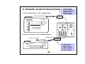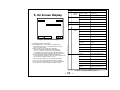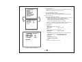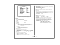
1
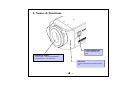
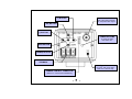
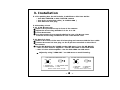
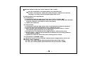
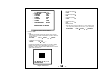
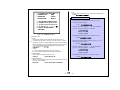
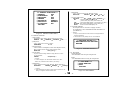
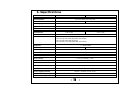
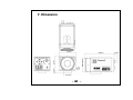
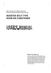
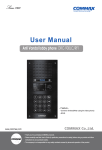
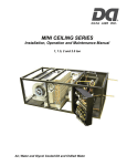
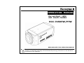
OPERATION MANUAL
Day and Night / WDR
OSD COLOR CAMERA
HCC-745NTW/PTW
READ AND KEEP THIS OPERATION MANUAL
The exclamation point within an equilateral triangle is intended to alert the user to the
presence of important operating and maintenance(servicing) instructions in the literature
- 1 accompanying the appliance.
CAUTION
RISK OF ELECTRIC SHOCK
DO NOT OPEN
CAUTION:
TO REDUCE THE RISK OF ELECTRIC
SHOCK, DO NOT REMOVE COVER
(OR BACK). NO USER SERVICEABLE
PARTS INSIDE.
PREFER SERVICING TO QUALIFIED
SERVICE PERSONNEL.
Indicate a potentially hazardous situation which if not avoided,
may result in minor or moderate injury. It may also be used to
alert against unsafe practices.
Warning:
This equipment generates and uses radio frequency energy
and if not installed and used properly, I.e., in strict accordance
with the instruction manual, may cause harmful interference
to radio communications. It has been tested and found to comply
with the limits for a Class A computing device pursuant to Subpart
J of Part 15 of FCC Rules, which are designed to provide reasonable
protection against such interference when operated in a commercial
environment.
Warning:
TO PREVENT FIRE OR SHOCK HAZARD, DO NOT EXPOSE THIS
APPLIANCE TO RAIN OR MOISTURE.
- 2 -
CAUTION FOR SAFE OPERATION
1. Water and Moisture
To prevent fire or shock hazard, do not expose this camera
to rain or moisture.
2. Servicing
Do not attempt to disassemble or repair by yourself.
You may be exposed to dangerous voltage or other hazards.
Note that all servicing is qualified service personnel.
Modifications not approved by manufacturer could
void the user's authority to operate the equipment.
3. Power Sources
To prevent electric shocks and risk of hazards, do NOT use
more than the specified power source.
4. Environment
Do not install too warm or too cold place. Recommended
operation temperature is between -5℃ and 60℃
5. Sunlight
Do not point the camera at the sun. CCD can be damaged.
6. Heavy Shock and Vibration
Do not drop the camera or subject it to heavy shock of
vibration.
7. Install on an Unstable Place
Do not place or install this camera on an unstable place,
stand, tripod, bracket or table. That may cause serious injury
to people or damage to appliance.
8. When operation is incorrect or a malfunction is observed
While operating, if any abnormal condition (strange sound,
smell or smoke) or a malfunction (no pictures, etc.) is
observed, stop using the camera immediately, turn the
power off, then contact your supplier.
9. Cleaning
Turn the power off and wipe off the dirt with a dry soft
cloth. If it is extremely dirty, use furniture cleaner to wipe it
off. To clean the lens, use a blower or lens cleaning
tissue. (available from any camera dealer)
10. Do not shoot any source of bright light.
If the objects contain very bright areas, bright vertical or
horizontal lines may appear on the screen. This is called
"smear" , a Phenomenon which often occurs with solid
- state pickups, and is not a malfunction.
11. Damage Requiring service
Unplug the camera from the power source and refer
servicing to qualified service personnel under the following
condition:
a. If the power-supply cord or plug is damaged.
b. If the camera has been exposed to rain or water.
c. If liquid has been spilled, or objects have fallen into the camera.
d. If the camera does not operate normally by following the operating
instructions. Adjust only those controls that are covered by the
operating instructions as an improper adjustment of other controls
may result in damage and will often require extensive work by a
qualified technician to restore the camera to its normal operation.
e. If the camera has been dropped or the cabinet has been damaged.
f . If the camera exhibits a distinct change in performance.
Warranty is not covered in case of natural disaster or wrong
Installation.
- 3 -
CONTENTS
1. Features
-----------------------
5
2. Names & Functions
-----------------------
6
3. Installation
-----------------------
8
4. Remote Control Connections
----------------------- 10
5. On Screen Display
----------------------- 11
6. Specifications
----------------------- 19
7. Dimensions
----------------------- 20
Thank you for using this OSD Color Camera with Day and Night, WDR. To
get the best efficiency, read carefully all instructions in this manual before
use, and keep this manual for reference. If you have any problems with
this camera, contact your supplier to service.
- 4 -
1. Features
Honeywell’s HCC-745NTW/PTW Series is a high sensitivity CCD color camera with high
sensitivity function
of Day & Night function and field integration technique.
▣ 1/3” Double Scan Color CCD ( NTSC: 410,000 / PAL: 470,000 )
▣ Outstanding BLC implementation with WDR(Wide Dynamic Range) function.
( 3 steps available : OFF / BLC / WDR )
▣ Adapted CS/C mount lens adjustable.
▣ Excellent signal-to-noise ratio of more than 50dB.
▣ High Sensitivity : Minimum illumination of 0.001lx @ F1.2, 50IRE, DSS On X510, Night mode
▣ 2-WAY Auto Iris : Video iris or DC iris lens can be used.
▣ 2-WAY Auto Iris : Video iris or DC iris lens can be used.
▣ OSD Control :
Flickerless, AGC, Manual shutter control, Maximum Fields Select,
WDR, BLC, Title and Camera ID setting, Sync Mode
▣ External synchronization with LINE LOCK(L/L) and Auto Detection.
▣ Auto White Balance : Auto white balance realizes true color reproduction within various
light sources.
▣ Remote Control through RS485 / RS232C
-. Camera ID : 0 ~ 255
-. Title : 10 characters
-. Camera ID & Title Display Position : Bottom Right, Bottom Left, Top Right, Top Left, No Display
-. AWB Mode : ATW, AWC, INDOOR, USER FIX, OUTDOOR, Fluorescent, MWB
-. BLC Mode : OFF, ON
-. WDR Mode : OFF, ON
-. ELC / ALC Mode : ELC (AUTO/Manual), ALC (VSD Lens/DC Lens)
-. Max Fields Control : x2 ~ x510
-. Sync. Control : AUTO, Internal, L/L (V.PH control)
-. Shutter Speed Control : 8 steps including Flickerless
-. Max AGC Control : OFF ~ 38dB
- 5 -
2. Names & Functions
LENS CONNECTOR
Connect Auto Iris Lens
plug
C/CS Mount Adaptor
• C-Mount lens : Turn Counterclockwise
• CS-Mount lens : Turn Clockwise
Set Screw
Loosen Locking Ring to adjust mounting
ring
- 6 -
(+) BUTTON
VIDEO OUTPUT
This is the output terminal
for composite video signal
(UP) BUTTON
(-) BUTTON
POWER ON LAMP
In power ON state,
this LED is ON .
MENU BUTTON
(DOWN) BUTTON
POWER INPUT
TERMINAL
Lens Type Select Switch
DC Lens : with no iris amp.
VSD Lens : with iris amp.
CAMERA CONTROL CONNECTOR
( Refer to 4. Camera Control Methods )
- 7 -
3. Installation
3.1 The packing box should include, in addition to this User Guide:
-. One HCC-745NTW or HCC-745PTW camera
-. One 6-pin connection cable ( G-113510-200 )
-. One Auto Iris lens plug
3.2 Mounting a Lens
3.2.1 C/CS Mount Lens
① Remove the protective cap in front of the camera.
② Adjust the mount ring whether it is for C or CS.
③ Loosen Set Screw.
④ Turn the mount ring counterclockwise in case of C-Mount Lens.
Turn the mount ring clockwise in case of CS-Mount Lens
3.2.2 Auto Iris Lens
① Remove the cover of the auto iris lens plug and connect with the lens cable.
② Connect the auto iris lens plug to the 4-pin lens terminal on the side of
the camera.
③ Set the EE MODE to ALC MODE on the OSD menu ( see 5.6 AE MODE)
-. Auto iris lens with no amplifier : Set the DC LENS on the OSD menu
-. Auto iris lens with amplifier : Set the VSD LENS on OSD menu
☞ Adjust by using “LENS ADJ.” on OSD menu to avoid hunting.
VSD LENS PIN CONFIGURATION
3
4
1
2
1. POWER(12V)
3. VIDEO SIGNAL
DC IRIS LENS PIN CONFIGURATION
3
4
1
2
①③
②④
2. NO CONNECTION
4. GND
Set the select switch to VSD
①③
②④
1. CONTROL- 2. CONTROL+
3. DRIVE+
4. DRIVESet the select switch to DC
- 8 -
④ Set the switch on the rear of the camera to DC or VSD.
☞ Use the connection recommended by the manufacturer.
(E4-191, Chuo Musen, Japan) For best practices, read the lens manual
carefully. You may need to set the flange back focus.
3.3 Flange back focus adjustment
3.3.1 Fixed Lens
a. Loosen the setscrew and set the lens focus ring to infinity ( ∞ ) .
b. Turn the back focus adjustment ring until you see a clear image (the distance
from the camera to the object is more than 23m).
c. Tighten the setscrew.
3.3.2 Zoom lens
a. Loosen the setscrew and set the lens to the maximum telephoto position.
b. Turn the back focus adjustment ring to adjust the focus.
c. Auto iris lens: Aim the camera at a comparatively dark object or reduce
the ambient light so that the iris is fully open.
d. Set the lens to its maximum wide angle position, then set the focus.
e. Repeat step b, c and d until the difference between the focusing positions
is as small as possible.
f. Tighten the setscrew when the best focusing point is found.
3.4 Connection of POWER supply
☞ Check the power source from the external power supply before power on.
☞ Power source capacity :
AC 24V, more than 500mA (Recommended Honeywell HAC-2450)
DC 12V, more than 500mA (Recommended Honeywell HDC-1260R)
- 9 -
4. Remote Control Connections
4.1 RS-232C connection ( HCC-745NTW/PTW )
Connect to Serial PORT
Serial Cable
RS232C
Serial Cable
( 9 Pin D-Sub )
1.
2.
3.
4.
5.
6.
Red : Not Use
Blue : RD(TxD)
Yellow : TD(RxD)
Black : GND
Red : Not Use
Black : Not Use
1.
2.
3.
4.
5.
6.
Red : Not Use
Blue : TRxYellow : TRx+
Black : Not Use
Red : Not Use
Black : Not Use
6P Cable
6P Cable
RD
2
2
RD ( TxD )
TD
3
3
TD ( RxD )
SG
5
4
GND
4
6
7
Connect internally
for communication
8
4.2 RS-485 connection ( HCC-745NTW/PTW-VR )
RS485 Converter
Connect to Serial PORT
Serial Cable
6P Cable
RS485
RS485 Converter
6P Cable
TRx+
3
TRx +
TRx-
2
TRx-
- 10 -
FUNCTION
5. On Screen Display
②
②, ③
ZOOM
DISPLAY
①
CAMERA ID
②, ③
⑤
①
④
⑥
DESCRIPTION
Dx2.5 >>TELE
Zoom TELE
Dx1.0 << WIDE
Zoom WIDE
None display
ID : 0
ID : 002
ID : 1 ~ 255
③
TITLE
■■…■■
See 5.11
④
Back Light
Non display
Back Light OFF
BL
Back Light ON
⑤
Shutter
Speed
1/60 (1/50)
NTSC:1/60, PAL :1/50
FL
NTSC:1/120, PAL:1/100
1/250
1/250
1/500
1/500
1/1000
1/1000
1/2000
1/2000
1/4000
1/4000
1/10000
1/10000
1/20000
1/20000
1/50000
1/50000
ATW
Auto Trace White Balance
AWC
One Push mode
IN
Indoor Preset (3200°K)
FRS
Fluorescent (4200°K)
USR
User mode
OUT
Outdoor preset (5400°K)
MWB
Manual mode
②, ③
<Fig5-1. OSD Information Display>
5.1 Understanding the On-Screen Display
a. Press MENU briefly to confirm the current operation setup.
The information (see Fig 5-1) will disappear after five seconds
if there is no button action.
b. When it zoom in or out pressing UP or DOWN key,
whole OSD Information will appear and then disappear.
Press (+) , (-) button, only upper part of OSD Information
( for displaying camera mode ) will appear and then disappear.
(It is for checking current whole camera mode and zoom position )
c. Even though the OSD message disappears the Camera ID
or Title will continue to display. If you do not wish to display the ID,
you can change the display position. (see 5.11)
Options are: Bottom Right, Top Left, Top Right, Non display.
OSD Format
⑥
WB MODE
* If you do not need to display the Operating OSD (for example,
for an external text overlay board), it can be set to OFF at all times
through a remote control using RS232C or RS485 connection.
<Table5-1. Operating OSD description>
- 11 -
<< SETUP MENU >>
GENERAL SETTING
AE MODE
WB MODE
NIGHTSHOT MODE
BLC/WDR MODE
PZM SETTING
CAMERA ID SETTING
SPECIAL FUNCTION
FACTORY DEFAULT
EXIT MENU
<<GENERAL SETTING>>
0
SYNC. LEVEL
98
BURST LEVEL
AUTO
SYNC. MODE
L/L
RETURN
5.2 Display SETUPMENU
a. Press and hold the MENU (center) button for 2 seconds to display the Setup
menu.
b. Press the UP or DOWN buttons to select a menu item.
5.3 Move from SETUPMENU to submenu
a. Press the MENU button to enter the selected submenu.
b. Press the + or – buttons to increase/decrease the value of the selected item.
5.4 Saving your Settings
When you are satisfied with your settings:
a. Press MENU for two seconds. The submenu is replaced by one of two messages:
① “QUIT?” : displays when you have not changed any settings.
Selecting QUIT exits OSD menu without saving any changed values.
② “SAVE?” : displays when values have been changed.
Selecting SAVE exits OSD menu and saves your changes.
b. Press + or – to select SAVE or QUIT and press MENU to exit OSD. Press UP or
DOWN buttons to cancel the SAVE/QUIT and return to the OSD.
5.5 General Setting
① SYNC. Level
: Adjust the proper SYNC. Level from 0~15.
SYNC. LEVEL
0 → 1 → … → 15
<Fig5-2. SETUP MENU change>
①
②
③
④
<<GENERAL SETTING >>
SYNC. LEVEL
0
BURST LEVEL
98
SYNC. MODE
L/L
V. PHASE
000
RETURN
② BURST Level
: Adjust the proper BURST Level from 0~255.
BURST LEVEL
0 → 1 → … → 255
③ SYNC. Mode
: To synchronize the vertical interval sync pulse of your camera with other
equipment to reduce the effect of picture roll on the monitor.
SYNC. MODE
AUTO → INTERNAL → L/L
④ Vertical Phase
: Adjust the proper phase in L/L.
V. PHASE 0 → 1 → … → 524
☞ Notice
L/L mode is not available in DC 12V power.
<Fig5-3. General Setting >
- 12 -
⑤ LENS ADJUSTMENT
: Adjust level for DC / VSD lens. While it is adjusting, it displays “Adj-ing”,
after it is completed, it displays “Done”.
LENS ADJ. Adj-ing → Done
<< AE MODE >>
ELC
① MODE
AUTO
② CONTROL
1/60
③ MAN. SHUTTER
OFF
④ MAN. AGC
Done
⑤ LENS ADJ.
60
⑥ BRIGHTNESS
34dB
⑦ MAX GAIN
510FLDS
⑧ MAX FIELDS
RETURN
☞ Notice
For the better adjustment, set LEVEL on VSD lens to middle value.
⑥ BRIGHTNESS
: Adjust level of Auto Iris. The smaller brightness value is, the darker it is,
because iris is closed more. On the contrary the bigger brightness value
is, the brighter it is, because iris is opened more.
BRIGHTNESS
⑦ MAX AGC
: Adjust maximum value of AGC gain.
MAX GAIN
OFF → 8dB → . . . . → 38dB
<Fig5-5. Setting Camera Linghting>
⑧ MAX FIELDS
: Compensate for low illumination. Adjust the maximum integration
fields to get a brighter dynamic image. The scene will be slower
than when set to OFF. The larger this field, the greater the noise
of the image. For more dynamic range, adjust the MAX FIELD and
increase the MAX AGC. .
OFF → 2FLDS → 3FLDS → 4FLDS → . . . .
MAX FLDS
5.6 AE mode
① MODE
: ELC – for a manual (fixed) lens.
ALC – for an automatic iris lens.
MODE
ELC → ALC
② CONTROL
CONTROL
0 ~ 99
→ 18FLDS → 19FLDS → 20FLDS → 40FLDS
→ 80FLDS → 160FLDS→ 320FLDS -> 510FLDS
AUTO
♦ ELC MODE
-. AUTO : Iris operates elctronic exposure automatically.
-. MANUAL : Adjust the iris by changing the high shutter speed
or AGC manually.
♦ ALC MODE
-. VSD LENS : Select for video-type lens
-. DC LENS : Select for direct drive-type lens.
③ MANUAL SHUTTER
: Adjust brightness with high shutter speed.
This field is not adjustable when the camera is set to ELC MODE, Auto.
MAN. SHUTTER
1/60 → 1/100 → . . → 1/50000
④ MANUAL AGC
: Adjust AGC gain at ELC MODE, Manual.
MAN. AGC OFF → 10dB → . . . → 34dB
☞ Notice
Accoring to mode, some menu will skip, not to adjust.
- 13 -
② CONTROL
ATW
IN
OUT
MANUAL
AWC
AWC
FLUORES.
USER
<< WB MODE >>
USER
① MODE
R/B CONT
② CONTROL
1
③ RED GAIN
2
④ BLUE GAIN
RETURN
AUTO
3200°K
5400°K
R<-->B
LOCK → PUSH
AUTO
4200°K
R/B CONT
1. MANUAL : Press + or – button to adjust RED GAIN, BLUE
GAIN automatically to fit Black Body.
2. PUSH : Press + or – button to start the AWC operation.
LoCK : Release the key to fit the present shooting scene’s
white balance
③ RED GAIN (USER mode)
RED GAIN
0 → 1 → …. → 254 → 255
<Fig5-6. White Balance Control>
5.7 White Balance Mode
① MODE
: To set how the camera tracks to accept different lighting conditions
within the color range of 2,500°K ~ 8,000°K.
ATW (Auto Trace White Balance Mode)
: Feedback system that automatically aligns the white balance
(2,500°K ~ 8,000°K).
IN (Indoor)
: General indoor scenes preset (3200°K)
OUT (Outdoor)
: Preset for outside environments and high contrast scenes where the
camera is focused on the darker (5400°K)
MANUAL
: RED GAIN, BLUE GAIN are changed depending Black Body
AWC (Auto/PushAuto)
: Performs faster action than ATW mode without an operating range
FLUORES. (Fluorescent)
: Office environments with fluorescent or tungsten lighting. Provides
lowest dynamic range of all presets (4200°K)
USER
: RED GAIN, BLUE GAIN are adjustable (0 ~ 255)
④ BLUE GAIN (USER mode)
BLUE GAIN
0 → 1 → …. → 254 → 255
- 14 -
⑤ NIGHT COLOR
: Set the color mode as B/W (monochrome) or COLOR in Night mode.
NIGHT COLOR
B/W → COLOR → ….
<< NIGHTSHOT MODE >>
AUTO
① MODE
3sec.
② DETECT TIME
3
③ D→N LEVEL
7
④ N→D LEVEL
B/W
⑤ NIGHT COLOR
RETURN
☞ Notice
MODE must be set to AUTO or ON.
<< BLC/WDR MODE >>
WDR
① MODE
8
② LEVEL
RETURN
<Fig5-7. NIGHTSHOT Control>
5.8 NIGHTSHOT MODE
① MODE
: The Nightshot menu allows you to set how the camera reacts to
changes in low light illumination and to set when the camera switches
between Night and Day modes.
AUTO – The camera removes or inserts IR cut filter by auto detecting
luminance.
ON – IR cut filter is removed (Night mode)
OFF – IR cut filter is inserted (Day mode)
MODE
OFF → AUTO → ON → ….
② DETECT TIME
: Sets the time – 1 to 10 seconds – before the camera switches to Day
or Night mode after detecting a low light condition.
DETECT TIME
1 sec. → 2 sec. → …. → 10 sec.
③ DAY to NIGHT threshold
: Determines the low light detection level – 1 to 10 – when the camera
switchs to Night mode. The lower the value, the darker the lighting
conditions befroe the camera switches.
D→N LEVEL
1 → 2 → 3 → …. → 15
④ NIGHT to DAY threshold
: Determines the low light detection level – 1 to 10 – when the camera
switches to Day mode. The higher the value, the brighter the lighting
conditions before the camera switches.
N→D LEVEL
15 → 9 → 8 → …. → 1
<Fig5-8. BLC/WDR MODE >
5.9 BLC/WDR MODE
① MODE
: Prevents the object in the center of the image from darkening
(silhouette effect) when there is excessive light from behind.
MODE
OFF → BLC → WDR → ….
WDR [Wide Dynamic Range] is one of Backlight Compensation,
you can watch not only the object in the center but also the objects
around clearly.
② LEVEL
: Adjust the proper level for WDR.
LEVEL
0 → 1 → 2 → …. → 15
☞ Notice
☞ Notice
MODE must be set to AUTO. D->N LEVEL must be set at least 2 less than
the N->D LEVEL setting.
- 15 -
If you set WDR ON, you will not be able to digital zoom in or out.
③ Horizontal Start position
H START
200
<< PRIVACY ZONE >>
ZONE 1
① ZONE NUM.
ON
② CONTROL
200
③ H START
300
④ H END
50
⑤ V START
100
⑥ V END
BLACK
⑦ PZM MASKING
RETURN
④ Horizontal End position
H END
300
⑤ Vertical Start position
V START
50
⑥ Vertical End position
V END
100
⑦ MASKING COLOR
: Choose the color to mask the PZM zone. 10 color (Black,Gray,
Light Gray,White,Red,Blue,Green,Yellow, Cyan, Magenta).
PRESS MENU TO MOVE
PZM MASKING
<Fig5-10. Privacy Zone Masking>
5.10 PRIVACY ZONE
① ZONE
:PZM(Privacy Zone Mask) is to hide the unwanted view to protect
privacy invasion. It works with Zoom/PAN/TILT operation. Select PZM
zone upto 8 zones.
ZONE NUM.
ZONE 1 → ZONE 1 → …. → ZONE 8
② CONTROL
: Set ON/OFF for each PZM Zone.
CONTROL
OFF → ON → ….
Press and hold the MENU (cernter) button for 2 seconds to display
PZM move menu. Move PZM to appropriate position by using
UP/DOWN/-/+ button. Press and hold the MENU button for 2 seconds
again to return previous menu.
UP:↑,DOWN:↓,-:←,+:→
RETURN:MENU
<Fig5-9. PZM move>
- 16 -
BLACK →D.GRAY → .. → MAGENTA
④ Title
: It is the name of Camera. It enters 10 characters including blank..
TITLE: ■ ■ ■ ■ ■ ■ ■ ■ ■ ■
<< CAMERA ID SETTING >>
① CAMERA ID
000
TITLE
② DISPLAY
③ POSITION
R.BOT
ⓐ
ⓑ
ⓒ
ⓓ
④
▣ How to Enter the Title ▣
Let’s enter the Title as “R1” , example
-. Select the position of title character by using (+) or (-) key.
The chosen position is blinking.
ABCDEFGHIJKLMNOPQRST
UVWXYZabcdefghijklmn
opqrstuvwxyz12345678
9!?#$%&<>*,.:;/+-=~■
TITLE: □ ■ ■ ■ ■ ■ ■ ■ ■ ■
-. Select the character “R” among ⓑ ~ ⓕ by using UP,DOWN,
(+),(-) key. The chosen character “R” is blinking.
TITLE : HONEYWELL
RETURN
7 8 9 AB C D E F
N PQ R S T U VW
e fgh i j k lm
<Fig 5-11. CAMERA ID SET >
-. Press MENU key, the character “R” is entered in the Title.
5.11 Camera ID SET
① ID SET
: Camera ID is indicating number assigned each Camera in case of
controlling many Cameras. It is from 0 to 255. But in case of 0, that is
not
displayed on screen. It is always displayed even though whole Operating
OSD is disappeared on the screen. But it is possible to make non display
and to choose display position (BOTTOM RIGHT, TOP RIGHT, TOP
LEFT) by RS-232C communication.
CAMERA ID
0 ~ 255
☞ caution
TITLE: R ■ ■ ■ ■ ■ ■ ■ ■ ■
-. Select the next position of title character by using (+) or (-) key.
The chosen position is blinking.
TITLE: R □ ■ ■ ■ ■ ■ ■ ■ ■
-. Select the character “7” among ⓑ ~ ⓕ by using UP,DOWN,
(+),(-) key. The chosen character “7” is blinking.
7 8 9 AB C D E F
N PQ R S T U VW
e fgh i j k lm
1. In case of Camera ID FIX model, it cannot be selected..
2. ID is not changed by MENU control through communication.
② DISPLAY MODE
: Choose which is to display Camera ID or Title.
DISPLAY
CAM ID → TITLE → ….
-. Press MENU key, the character “7” is entered in the Title.
TITLE: R 7 ■ ■ ■ ■ ■ ■ ■ ■
③ DISPLAY POSITION
: Choose where is to display Camera ID or Title on Right Bottom, Left Top,
Right Top or not to display.
POSITION
R.BOT → L.TOP → R.TOP → NONE
- 17 -
<< SPECIAL FUNCTION >>
OFF
① MIRROR
10
② SHARPNESS
OFF
③ NEGATIVE
OFF
④ FREEZE
9600bps
⑤ BAUDRATE
DEFAULT
⑥ PROTOCOL
ALL
⑦ F.OSD DISP
RETURN
⑥ PROTOCOL
: Use to communicate through RS232C, RS485.
PROTOCOL
DEFAULT → VCL → KD6 → P/D → ....
⑦ Function OSD Display
OSD DISP
ALL → NONE → TOP → BOTTOM → ....
ALL
: Whole Function OSD display
( Focus Mode, Key state, Zoom Ratio, ID )
TOP
: Only Upper OSD display ( Focus Mode, key state )
BOTTOM : Only Lower OSD display ( Zoom Ratio, ID )
NONE
: Whoe Function OSD display not.
5.13 FACTORY DEFAULT
: All changed data are returned to shipping condition.
For Initialization, select “RESTORE FACTORY SETTING” and
push MENU key.
<Fig5-12. SPECIAL FUNCTION >
5.12 SPECIAL FUNCTION
① Mirror Mode
: Mode ON is Mirror Mode, OFF is general screen state.
MIRROR
OFF → H MIRROR → V MIRROR → FLIP . . . .
☞ caution
1. Keep in mind that this mode return all changed data to
shipping condition.
2. Some menu as ID,TITLE, etc are not initialized.
<< RESTORE DEFAULT >>
① RESTORE FACTORY SETTING
RETURN
② Sharpness
: Use to change the contour of Scene.
SHARPNESS
0 ~ 15
③ Negative Mode
: Use for Positive and Negative mode. ON is Negative mode,
OFF is Positive mode namely general screen state.
NEGATIVE
OFF → ON → ….
<Fig5-13. RESTORE DEFAULT>
5.14 EXIT MENU
① SAVE AND EXIT
: Exit OSD MENU with saving all changed data.
④ Freeze Mode
: It pause current image. ON is to stop, OFF is to return
to normal state.
FREEZE
ON → OFF → ….
② EXIT
: Exit OSD MENU withoout saving all changed data.
☞ caution
1. Freeze image is not saved after Power OFF / ON .
That’s why it doesn’t have memory for saving.
⑤ BAUD RATE
: Use to communicate through RS232C, RS485, RS232TTL .
BAUDRATE
4800bps → 9600bps → …. → 312kbps
☞ caution
1. When Baud Rate of Camera and external system is not
same, it happens Communication fail.
- 18 -
<< EXIT MENU >>
① SAVE AND EXIT
② EXIT
RETURN
<Fig5-14. EXIT MENU>
6. Specifications
Model Name
HCC-745NTW
HCC-745PTW
Pick-up Device
Total/Effective Pixels
1/3” Sony Double Scan Color CCD
410,000 / 380,000
Scanning System
525 lines, 2:1 Interlace
Digital Zoom Ratio
Sync System
H.Resolution
X1.0 ~ x2.5 can be adjustable
Internal / External (L/L ), Auto detecting selectable
480 TV lines
S/N Ratio
Min. illuminance
470,000/440,000
470 TV lines
more than 50 dB ( AGC OFF )
0.2lx @50IRE, AGC 38dB, Night OFF;
0.01lx @50IRE, AGC 38dB, Night OFF, DSS 510fields;
0.01lx @50IRE, AGC 38dB, Night ON;
0.001lx @50IRE, AGC 38dB, Night ON, DSS 510fields;
Brightness
Shutter Speed
Field Integration
Mirror
0 ~ 99 adjustable
1/60 ~ 1/10,000
1/50 ~ 1/10,000
x2 ~ x510 adjustable
Horizontal / Vertical / Filp (Horizontal + Vertical)
Day & Night Mode
Privacy Zone
AGC
White Balance
ON / OFF / AUTO
ON ( up to 8 Zones ) / OFF
ON ( 8 ~ 38dB ) / OFF
ATW / AWC / OnePush / Indoor / Outdoor / MWB / User / Fluorescent
BLC / WDR
BLC : ON / OFF, WDR : ON / OFF
Remote Control
RS-232C (basic) / RS-485 (option)
Power Supply/Consump.
DC12V ± 2V,AC24V ±10% (5.0 W)
Operation/Storage Temp.
-10 ~ 60 ℃( Recommended -5 ~ 50 ℃) / -20 ~ 60 ℃
Dimension / Weight
68 x 56 x 120 (mm) / less than 410g
- 19 -
7. Dimension
- 20 -
MEMO
Honeywell Co., Ltd.
Address : 17F, Kukje Center Building 191,
Hankangro -2ga, Yongsan-gu,
Seoul 140-702, Korea
Phone : 82-2-799-6109, 6108, 6107, 6292
Fax : 82-2-749-6119
Printed in Korea
http : //www.honeywell.co.kr/security/english
E-mail : [email protected]
- 21 -
G-113608-001