1
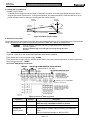
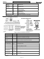
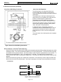
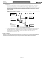
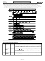
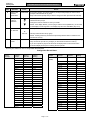
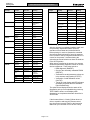
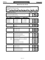
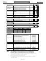
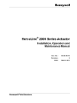
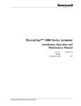
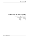
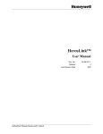
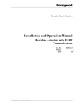
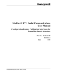
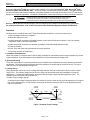
62-86-25-14
February 2007
Quick Start Guide for Herculine 2000 Series Actuators
Honeywell’s HercuLine® 2000 series actuators are available in four versions: HercuLine® 2000, HercuLine® 2001,
HercuLine® 2002, and HercuLine® 2003. All are low torque, precision electric rotary actuators. This guide provides
you with mechanical and electrical installation information required to mount and connect the HercuLine® 2000 Series
Actuator to your specific application. Installation considerations, electrical and safety precautions should be observed.
An external disconnect switch must be installed to break all current carrying
conductors connected to the actuator. Turn off power before working on
conductors. Failure to observe this precaution may result in serious personal injury.
Refer to the Model Selection Guide on Pages 9 and 10 to determine which features and functions are on your model.
For additional information, refer to HercuLine Series 2000 Installation/Operation Manual # 62-86-25-10
Overview
The procedures to install the HercuLine® 2000 Series actuator and place it in service require that you:
1. Select a suitable location for installation.
2. Mount the actuator securely.
3. Install mechanical connections or linkage between control arm and final control element. Use HAL software
application to aid in mechanical installation.
4. Make all electrical connections for actuator according to local and national electrical codes.
5. Power up actuator.
6. Enter, verify and adjust set up parameters for proper operation.
7. Check the operation of the Actuator
1. Installation Considerations
Mount the actuator in a location where it will be easily accessible for maintenance and for manual operation by means
of the hand wheel. The exact location must be determined in accordance with the linkage used.
2. Actuator Mounting
Firmly bolt the actuator to a mounting surface that will not distort when subjected to the torque stresses generated by
the actuator. The output shaft of the actuator should be parallel to the output shaft of the driven device. The output
shaft crank arm is fully adjustable through 360°.
3. Linkage Set-up
Many applications require the use of a linkage assembly and often the final control element does not have a linear
torque curve. The actuator linkage can be set up to achieve an optimal delivered torque distribution for specific
applications. To assist with linkage design, Honeywell offers a linkage analysis software application (HAL). The
software can be ordered as P/N 51197910-001.
Constant Torque Linkage (typical)
A constant torque linkage is employed when it is desired to provide a linear torque profile throughout the full range of
final control element travel. In this situation, the actuator and driven crank arms will be set-up proportionally with
respect to each other.
Vertical
Centerline
45°
Vertical
Centerline
45°
45°
45°
Linkage
Start
Drive Unit
Crank Arm
Stop
Close
Horizontal Offset
Open
Damper
Crank Arm
a/n 23199
Figure 1 Constant Torque Linkage
Page 1 of 10
62-86-25-14
February 2007
Quick Start Guide for Herculine 2000 Series Actuators
3. Linkage Set-up (continued)
Variable Torque Linkage
A variable torque linkage is employed when it is desired to provide a non-linear torque profile throughout the full
range of final control element travel. In this general situation, the actuator and driven crank arms will be set up to
provide a higher torque for seating or unseating the final control element.
Vertical
Centerline
Vertical
Centerline
45°
Actuator
Crank Arm
45°
Linkage
Close
5°
Open
Damper
Crank Arm
Horizontal Offset
a/n 23200
Figure 2 Variable Torque Linkage
4. Electrical Connections
The actuator terminal connections for the field wiring are located behind the cover on the actuator case. Power and field
wiring is brought into the actuator through two access holes located on the side of the actuator case.
Use both openings: one for low level wiring (control signal) and the other for high
level wiring (120Vac).
Do not run both the High Level and Low Level wiring through the same
opening.
Recommended Minimum Wire Size
In general, copper wire used unless locally applicable codes dictate otherwise.
Earth ground wire to common power supply -14AWG
Earth ground wire to single actuator. 120/240 Vac line leads. +24 V and common signal leads. Common signal leads,
relays, and aux switches – 18AWG
HercuLine® 2000 Wiring Connections
158 ohm
158 ohm
Install resistors to convert 1000 ohm
potentiometer to 135 ohms
1
1 REQUIRED ONLY IF AUTO/MANUAL
SWITCH IS PRESENT
Figure 3 HercuLine® 2000 connections
Connection
Terminal
Description
Hot
1
Hot wire for 120/240VAC main supply.
NOTE:Use only if Auto/Manual switch is present.
Neutral
2
Neutral wire for 120/240VAC main supply
Auto/Manual
Switch Contact
3
Switch contact to indicate setting of actuator AUTO/MANUAL
switch.
4
Switch is closed when actuator is “NOT-IN-AUTO”
Page 2 of 10
62-86-25-14
February 2007
Quick Start Guide for Herculine 2000 Series Actuators
CW from
Controller
5
CW Motor Drive
CCW from
Controller
6
CCW Motor Drive
Potentiometer #1
7
8
9
Clockwise-End
Slidewire feedback
Counterclockwise-End
Potentiometer #2
10
11
12
Clockwise-End
Slidewire feedback
Counterclockwise-End
Protective Ground
Ground wire connection for main supply
HercuLine® 2001/2002 Wiring Connections
HART
Communications
Connection
+
_
HART connection using
external Turck connector
Auxiliary
Connector
_
+
Brown
Blue
Black
Black Wire Not Used
Figure 3 HercuLine® 2001/2002 Connections
Connection
Terminal
TB1
Description
Hot
1
Hot wire for 120/240VAC main supply
Neutral
2
Neutral wire for 120/240VAC main supply
Protective Ground
3
Ground wire connection for main supply
Auto/Manual Switch
Contact
4
5
Switch contact to indicate setting of actuator AUTO/MANUAL switch.
Switch is closed when actuator is “NOT-IN-AUTO”
6
TB3
4 to 20mA Output*
1 (+)
2 (-)
Analog signal output
Feedback
3
Feedback signal used in conjunction with 4 to 20mA OUTPUT voltage
when using Slidewire Emulation
4 to 20mA Input
4 (+)
5 (-)
Analog signal input
Modbus
Communication
6 (+)
7 (-)
8 Shield
Connection for RS485 Modbus loop wires
HART
Communications
4 (+)
5 (-)
HART Communication is
4-20 mA only.
Digital Input
9 Com
10 Input
Customer’s contact closure
* Optional
Page 3 of 10
62-86-25-14
February 2007
Quick Start Guide for Herculine 2000 Series Actuators
4. Electrical Connections (continued)
HercuLine® 2003 Wiring Connections
HercuLine® 2003 Operation
The 2003 actuator is uni-directional (it does not
reverse rotation with a reversal in control action).
Figure 5 illustrates the internal wiring and the external
connections.
The smaller insert of the figure describes the limit
switch action for one complete cycle. When the twoposition controller detects a sufficient fall in
temperature in a heating application, the switch
portion between the “4” and “5” terminals will close.
The motor then rotates for 180º or until the opening
switch breaks (stops are adjustable, factory set at
180º), and stops in full open position.
A subsequent rise in temperature causes the
controller to close the switch between the “4” and “6”
terminals when the motor will start to rotate (in the
same direction) for 180º or until the closing switch
breaks.
The motor stops in the closed position and completes
one cycle.
Figure 5 HercuLine® 2003 Wiring Connections
Series 90 Control – HercuLine® 2001 model only
Series 90 Controls are commonly used in building environmental systems and flame safeguard systems to provide
modulating control. The control is affected by balancing a 135 ohm potentiometer. The HercuLine 2001 provides
an emulation of this system as follows. The current output is used to excite the potentiometer in the controller. To
do this it is set permanently at 11 mA. This produces a 1.5 volt span. The wiper is then connected to the
HercuLine 2001 input, which is operating in voltage mode. The returns from both the input and the output are tied
together.
Series 90 terminals are typically color coded white, red and blue. Conventionally, red is the wiper and white and
blue are the two ends of the potentiometer. On a drop in temperature, the wiper moves toward the blue terminal.
Connections
TB3
4-20mA output
1+
White
2-
4-20mA input
4+
Red
5-
Blue
Figure 6 Series 90 connections
Page 4 of 10
62-86-25-14
February 2007
Quick Start Guide for Herculine 2000 Series Actuators
Considerations
1. This connection performs an emulation of a series 90 motor. If the controller being used is also an
emulation of a Series 90, the connections required may be different. Shown in Figure 7are the
connections found necessary to connect a T775 controller through an S443A S90 Auto/Manual Control.
If the controller has the capability to provide a 4/20 or voltage output, it is easier to use that mode. It
will require only two wires and it will allow the independent use of the 4/20 output. If help is required,
contact Honeywell.
2. Due to variations in the definition of rotation directions, it may be necessary to reverse the action of the
actuator from CCW to CW or vice versa.
Auto
I out from
HercuLine2001
W
W
T775 B 3
W
T775 W 1
R
+ Signal to
HercuLine2001
R
Man
GND to
HercuLine2001 (2)
B
B
T775 R 2
Figure 7 T775 Controller connections
3. In the T775 controller manual there are several examples of using resistances or potentiometers as
high and low limit controls. Because of the mode of emulation of Series 90, it is likely that these
connections will not work as intended. Instead, use the output or input limits which are
programmable in the HercuLine® 2001.
5. Power up actuator.
Depending on which power supply selection is ordered for your actuator, wire the power input (MAIN POWER) as
described in the previous tables and figures. Wiring must conform to national and local electrical codes.
Page 5 of 10
62-86-25-14
February 2007
Quick Start Guide for Herculine 2000 Series Actuators
6. Enter, verify and adjust set up parameters for proper operation. (2001/2002 with optional display)
Pressing the SET UP key on the keypad provides access to the various set up groups and allows you to set up
operating parameters, (such as input types and alarms), set communications, and check actuator status. The Table
below lists the set up groups that are available by using the SET UP and FUNCTION keys on the keypad.
Setup Groups
INPUT
Function Prompts
IN TYP
INP HI
FSTYPL
RELAYn
INP LO
FsVALL
CHAR
Y0 VAL
…
Y20 VAL
RTYPny
Rny VAL
Rny E*
Rny HL
RLYnHY
CUROUT
CUROUT
COMM
COMM
ADDRES
DIGINP
DIGINP
EndPos
DISPLA
DECMAL
LOCK
LOCKID
STATUS
FAILSF
RAMTST
VERSON
SPEED
DRVINF
MAINT
FILTYP
EUNITS
LOCK
LREP
LCAL
TEMP
TEMPHI
Direct
CUSTOM
Rny HL
Dband
FSTYPH
X0 VAL
RTYPny
…
FsVALH
X20 VAL
Rny VAL
Rny E*
n = 1,2,3 or 4 y = 1 or 2
BAUD
XmtDLY
DBLBYT
UNITS
MAENAB
SEETST
POWER
CFGTST
CALTST
ROTATE
TAG
ACSTAL
STARTS
MFGDAT
REPTYP
TEMPLO
RL2CNT
RL3CNT
RL4CNT
REGN0
DATSAV
PASSWD
MANRST
LD CAL
…
LD CFG
RL1CNT
REGN9
TOTDEG
RESTRT
You can use this procedure to access the set up groups and select all parameters.
Set Up Procedure Using Display and Keypad
Step
Operation
Press
Result
1
Enter Set Up
Mode
SET UP
Upper Display = SET UP-Lets you know you are in the set up mode and a set up group
title is being displayed in the lower display.
Lower Display = INPUT-This is the first set up group you see when you press SET UP.
2
Select any
Set Up
Group
SET UP
Successive presses of the SET UP key will display the other set up group titles. You can
or
keys to scroll through the set up groups in both directions. Stop
also use the
at the set up group title that describes the group of parameters you want to configure.
Then proceed to the next step.
3
Select a
Function
Parameter
FUNCTION
Upper Display - Shows the current value or selection for the function prompt in the
selected set up group.
Lower Display - Shows the first function prompt within the selected set up group.
Page 6 of 10
62-86-25-14
February 2007
Quick Start Guide for Herculine 2000 Series Actuators
Step
Operation
Press
4
Select other
function
parameters
FUNCTION
5
Change the
Value or
Selection
Result
Successive presses of the FUNCTION key will sequentially display the other function
prompts of the selected set up group.
Stop at the function prompt that you want to change, and then proceed to the next step.
These keys increase or decrease the value, or display the next available selection for the
selected function prompt.
or
Change the value or selection to meet your needs.
NOTE: If the display flashes, you are trying to make an unacceptable entry, or the value
on the display is at its range limit. The display may also show “KEYERR” (Key error).
6
Enter Value
or Selection
FUNCTION
This key selects another function prompt.
or
SET UP
This key selects another set up group.
NOTE: Pressing either key will cause the previously selected value or selection to be
entered into memory.
7
Exit Set Up
mode
DISPLAY
Exits set up mode and returns actuator to the same state it was in immediately preceding
entry into the set up mode. Any changes you have made are stored in memory.
If you do not press any keys for 30 seconds, the display times out and reverts to the
mode and display shown prior to entering the set up mode.
Record your selections on the Configuration Record Sheet
.
Configuration Record Sheet
Factory
Setting
Group
Prompt
Function
Prompt
IN TYP
From MSG
INPUT
(CONT)
X14 VAL
70
INP HI
100
X15 VAL
75
INP LO
0.0
X16 VAL
80
FILTYP
LPAS
X17 VAL
85
LPFILT
0.5
X18 VAL
90
DIRECT
CCW
X19 VAL
95
DBAND
0.5
X20 VAL
100
FSTYPH
UP
FSVALH
100
FSTYPL
DOWN
FSFVALL
0
CHAR
LINR
CUSTOM
EQUL
X1 VAL
5
X2 VAL
10
X3 VAL
15
X4 VAL
20
X5 VAL
25
X6 VAL
30
X7 VAL
35
X8 VAL
40
X9 VAL
45
X10 VAL
50
X11 VAL
55
X12 VAL
60
X12 VAL
65
Group
Prompt
Function
Prompt
INPUT
Value or
Selection
Page 7 of 10
Value or
Selection
Factory
Setting
Y1 VAL
5
Y2 VAL
10
Y3 VAL
15
Y4 VAL
20
Y5 VAL
25
Y6 VAL
30
Y7 VAL
35
Y8 VAL
40
Y9 VAL
45
Y10 VAL
50
Y11 VAL
55
Y12 VAL
60
Y13 VAL
65
Y14 VAL
70
Y15 VAL
75
Y16 VAL
80
Y17 VAL
85
Y18 VAL
90
Y19 VAL
95
Y20 VAL
100
62-86-25-14
February 2007
Quick Start Guide for Herculine 2000 Series
Group
Prompt
Function
Prompt
RELAYn
CU OUT
COMM
DIGINP
DISPLA
LOCK
STATUS
DRVINF
Value or
Selection
Factory
Setting
Group
Prompt
Function
Prompt
Value or
Selection
Factory
Setting
RTYP
NONE
MAINT
TEMP
NONE
RnyE
X1
TEMPHI
X1
RnyVAL
0.0
TEMPLO
RnyHL
LO
hh:mm:ss
ACST
Read Only
RLYnHY
0.0
STARTS
Read Only
CUROUT
NONE
Depends on
MSG
Accumulated
Motor Starts
RnCNT
n=1,2,3,or4
Read Only
Relay Cycle
Counts
REGNn
n= 0 to 9
Read Only
Accumulated
Motor Starts
TOTDEG
Read Only
Total Degrees of
Motor Travel
0.0
COMM
DIS
ADDRES
1
BAUD
19.2
XmtDLY
20ms
DATSAV
DIS
DBLBYT
FP B
PASSWRD
Nnnn
DIGINP
NONE
MANRST
NONE
EndPos
0
LD CAL
NONE
DECMAL
8888
EUNITS
PCNT
UNITS
ENGL
LOCKID
0
LOCK
NONE
MAENAB
ENAB
FAILSF
Read Only
Read Only
RAMTST
Read Only
Read Only
SEETST
Read Only
Read Only
CFGTST
Read Only
Read Only
CALTST
Read Only
Read Only
VERSON
Read Only
Read Only
SPEED
Read Only
Read Only
POWER
Read Only
Read Only
ROTATE
Read Only
TAG
Read Only
Read Only
Factory Set
Factory Set
LCAL
Factory Set
Factory Set
REPTYP
Factory Set
Factory Set
DIS
After the actuator is completely installed, wired, and
the preliminary adjustments made, check the
operation of the actuator and controlled device
before placing it in service. Operate the controlled
device and check its direction of travel in response
to an increase of the input signal and make sure it is
correct for the process. Actuators having the
optional auto-manual switch must have the knob set
in the AUTO position.
When power is applied to the actuator, the actuator
electronics performs a diagnostic routine on various
device components. These tests include a:
• RAM diagnostic (RAMTST),
• Check of the electrically eraseable PROM
(SEETST),
• Verification that valid parameter values are
in the actuator configuration (CFGTST),
• Verification of valid calibration values
(CALTST)
• Test of the local display and LED indicators
(all display segments and LED indicators
light simultaneously).
Read Only
LREP
DIS
RESTRT
7. Start up/Operation
6 alpha
characters
MFGDAT
LD CFG
The optional local display shows the status of the
diagnostics as they are completed during power up.
TEST DONE is shown on the display when
diagnostics are complete and actuator should be in
AUTO mode.
If the Actuator Motor is “Hunting” (Motor does not
drive to a position and stop) the process control
loop is not tuned correctly. Refer to the Instruction
Manual for your controller on how to tune a loop.
Page 8 of 10
62-86-25-14
February 2007
Quick Start Guide for Herculine 2000 Series
Model Selection Guide
Instructions
Select the desired key number. The arrow to the right marks the selection available.
Make the desired selections from Tables I thru VIII using the column below the arrow.
A dot ( ) denotes unrestricted availability.
Key Number
____
I
___
II
-
___
III
-
___
IV
-
___
V
- __
VI
- ______
KEY NUMBER - Motor Selection
Basic Motor Unit (no electronics)
Basic Motor Unit plus Digital Electronics
Enhanced Performance Motor Unit with Non-contact Position Sensing
Unidirectional Motor (M640D Replacement)
VII
-
VIII
-
_
90 degrees
150 degrees
360 degrees
IX
-
050
100
200
400
600
090
150
360
TABLE III - POWER SUPPLY
Single Phase
100 - 130 Vac, 60 Hz
100 - 130 Vac, 50 Hz
200 - 240 Vac, 60 Hz
200 - 240 Vac, 50 Hz
126
125
246
245
TABLE IV - ANALOG INPUT/OUTPUT SIGNALS
Input
3 Wire Drive up/down
0/4-20 mA, 0/1-5 Vdc, 0-10 Vdc
0/4-20 mA, 0/1-5 Vdc, 0-10 Vdc
0 to 135 ohm input (Series 90 control)
Contact Input for 2003
Output
None
Dual 1000 Ohm (1000 ohms over 150 degrees)
(Note 1)
Dual 1000 Ohm (1000 ohms over 90 degrees)
(Note 1)
Slidewire Emulation
Slidewire Emulation
0/4-20mAdc (0/1-5 Vdc, 0-16 Vdc)
0/4-20mAdc (0/1-5 Vdc, 0-16 Vdc)
0__
2__
3__
4__
6__
_ 00
_ 15
_ 19
_ 60
_ 65
_ 80
_ 85
TABLE V - SWITCH AND RELAY OUTPUTS (2 end-of-travel limit switches are standard)
Auxiliary Outputs
No Auxiliary Switches
2 Auxilliary Switches
4 Auxilliary Switches
Relay Outputs
No Relays
2 Programmable Relay Outputs
2 Programmable Relay Outputs
4 Programmable Relay Outputs
0_
2_
4_
_0
_2
_3
_4
Page 9 of 10
__
Availability
Selection
2000
2001
2002
2003
TABLE I - TORQUE & SPEED SELECTION (speed per 150 degree rotation)
Torque, lb-in/(N-M)
50Hz (90°/150°)
60Hz (90°/150°)
50 / (6.0)
4.5 / 7.5 sec
4 / 6 sec
100 / (11.5)
9 / 15 sec
7 / 12 sec
200 / 22.5)
18 / 30 sec
15 / 25 sec
400 / (45.0)
36 / 60 sec
30 / 50 sec
400 / (45.0)
54 / 90 sec
45 / 75 sec
TABLE II - ROTATION
Travel
_
a
b
c
62-86-25-14
February 2007
Quick Start Guide for Herculine 2000 Series
Availability
2000 2001 2002 2003
TABLE VI - OPTIONS
Local keypad/
display
Local Auto/
manual switch
Handwheel
Certificates
Approvals
Shipped Rotation
(Note 2)
No local display interface supplied
Integrally mounted local display/keypad interface
No auto/manual switch
Auto/manual switch with "Out of Auto Contact"
Auto/manual switch with "Out of Auto Contact"
No Handwheel
Handwheel
None
Certificate of Conformance
UL Type 4/IP66, CSA
(Note 4)
CE
Counter clockwise shaft rotation on increasing signal
Clockwise shaft rotation on increasing signal
Selection
0_ _ _ _ _
1_ _ _ _ _
_ 0_ _ _ _
_ 1_ _ _ _
_ 2_ _ _ _
_ _ 0_ _ _
_ _ 1_ _ _
___0__
_ _ _ 1_ _
_ _ _ _ 0_
_ _ _ _ 1_
_ _ _ _ _0
_ _ _ _ _1
TABLE VII - COMMUNICATIONS/PROTOCOL
None
No communications option board or protocol
Modbus RTU RS485 RS-485 Modbus compliant - standard with EEU
HART 5
HART Communications Protocol
0
1
2
TABLE VIII - MANUALS
Standard
English
0
TABLE IX - FACTORY OPTIONS
Factory Options
None
Restrictions
Restriction
Letter
a
b
c
ACCESSORIES
Mounting Hardware
Linkage Assembly
HART
Handheld Config.
(Note 3)
Remote Mount
Control
V51 Valve Kits
Notes:
00
Available Only With
Table
Selection
IV
_ 00
150
II
II
090
Not Available With
Table
Selection
IV
_ 60, _ 80
090
II
II
150
Mounting plate adapter for Barber Colman Series MP495
Mounting plate adapter for Landis & Staefa SQM53/56
Direct Couple Valve Hardware
North American Valve Retrofit Kit
Ball joint for 5/16" dia. Pushrod
Pushrod 12 in. (304,5 mm) long, 5/16 " dia.
Pushrod 18 in. (457,2 mm) long, 5/16 " dia.
Pushrod 24 in. 609,6 mm) long, 5/16 " dia.
Pushrod 48 in. (1219,2 mm) long, 5/16 " dia.
Turk Cable for Handheld Connection
TM
HercuLink PC and Palm PDA Software
Battery powered 232/485 converter with cable
Remote 4-20 mA requires 135 ohm fdbk, 120V 50/60Hz
Remote 4-20 mA requires 1000 ohm fdbk, 120V 50/60Hz
Remote 4-20 mA requires 135 ohm fdbk, 220V 50/60Hz
Remote 135 ohm input requires 135 ohm fdbk, 120V 50/60Hz
51452354-501
51452354-502
51452354-503
51452354-511
51452354-504
51452354-505
51452354-506
51452354-507
51452354-508
51452352-501
51452354-509
51452354-510
R7195A1031
R7195A1056
R7195A1064
R7195B1021
HercuLine 2000 V51 2.5" - 3" Valve Mounting Kit
51452354-513
HercuLine 2000 V51 4" Valve Mounting Kit
51452354-514
1. 135 ohm available by parallelling 1K potentiometer with 158 Ohm resistor (supplied).
2. HercuLinkTM software (pn 51452354-509), RS232/485 converter (pn 51452354-510),
customer supplied PalmTM PDA running OS3.5 or higher and Palm serial cable are required
for the 2001 and 2002 actuators if no display is selected.
3. Requires PDA manufacturer's serial interface cable.
4. CSA approval is good for 75°C and a maximum relay load of 3.5 amps or 70°C with a
relay load of 5 amps.
Page 10 of 10