1
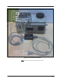
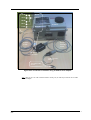
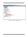
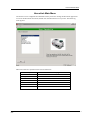
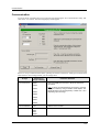
HercuLink™ PC
User Manual
Industrial Measurement and Control
Doc. No.:
62-86-25-13
Release:
1
Last Revision Date:
8/06
Notices and Trademarks
Copyright 2006 by Honeywell
Release 1 August 2006
Warranty/Remedy
Honeywell warrants goods of its manufacture as being free of defective materials and faulty workmanship.
Contact your local sales office for warranty information. If warranted goods are returned to Honeywell during the
period of coverage, Honeywell will repair or replace without charge those items it finds defective. The foregoing
is Buyer's sole remedy and is in lieu of all other warranties, expressed or implied, including those of
merchantability and fitness for a particular purpose. Specifications may change without notice. The information
we supply is believed to be accurate and reliable as of this printing. However, we assume no responsibility for its
use.
While we provide application assistance personally, through our literature and the Honeywell web site, it is up to
the customer to determine the suitability of the product in the application.
CE Conformity
This product conforms with the protection requirements of the following European Council Directive:
89/336/EEC, the EMC directive and 73/23/EEC, the Low Voltage Directive. Conformance of this product with
any other “CE Mark” Directive(s) shall not be assumed.
Attention
The emission limits of EN 50081-2 are designed to provide reasonable protection against harmful interference
when this equipment is operated in an industrial environment. Operation of this equipment in a residential area
may cause harmful interference. This equipment generates, uses, and can radiate radio frequency energy and
may cause interference to radio and television reception when the equipment is used closer than 30 m to the
antenna(e). In special cases, when highly susceptible apparatus is used in close proximity, the user may have to
employ additional mitigating measures to further reduce the electromagnetic emissions of this equipment
Industrial Measurement and Control
Honeywell
1100 Virginia Drive
Fort Washington, PA 19034
HercuLink and HercuLine are trademarks of Honeywell
Palm is a trademark of Palm Inc.
Other brand or product names are trademarks of their respective owners.
Release 1
8/06
HercuLink™ User Manual
iii
About This Document
Abstract
This manual describes the installation, set up, and operation of HercuLink PC software for use with
Honeywell actuators.
References
The following list identifies all documents that may be sources of reference for material discussed in this
publication.
Document Title
Doc ID
HercuLine 2000 Series Actuator Specification
61-86-03-14
HercuLine 2000 Series Actuator Model Selection Guide
62-86-16-21
®
51-52-25-66
®
Modbus RTU Serial Communications User Manual
Configuration/Remote Calibration Interfaces for HercuLine
Actuators
51-52-25-103
HercuLine 2000 Series Actuator Installation, Operation and
Maintenance Manual
62-86-25-10
10260S HercuLine® Smart Actuator Installation, Operation and
Maintenance Manual
62-86-25-08
11280S HercuLine® Smart Actuator Installation, Operation and
Maintenance Manual
61-86-25-09
Modbus RTU Serial Communications User Manual
Contacts
World Wide Web
The following lists Honeywell’s World Wide Web sites that will be of interest to our customers.
Honeywell Organization
WWW Address (URL)
Corporate
http://www.honeywell.com
Industrial Measurement and Control
http://www.honeywell.com/imc
Telephone
Contact us by telephone at the numbers listed below.
Organization
United States and Canada
iv
Phone Number
1-800-423-9883
1-800-525-7439
Honeywell
HercuLink™ PC - User Manual
Tech. Support
Service
Release 1
8/06
Symbol Definitions
The following table lists those symbols that may be used in this document to denote certain conditions.
Symbol
Definition
This DANGER symbol indicates an imminently hazardous situation, which,
if not avoided, will result in death or serious injury.
This WARNING symbol indicates a potentially hazardous situation, which, if
not avoided, could result in death or serious injury.
This CAUTION symbol may be present on Control Product instrumentation
and literature. If present on a product, the user must consult the
appropriate part of the accompanying product literature for more
information.
This CAUTION symbol indicates a potentially hazardous situation, which, if
not avoided, may result in property damage.
WARNING
PERSONAL INJURY: Risk of electrical shock. This symbol warns the user of a
potential shock hazard where HAZARDOUS LIVE voltages greater than 30 Vrms,
42.4 Vpeak, or 60 Vdc may be accessible. Failure to comply with these
instructions could result in death or serious injury.
ATTENTION, Electrostatic Discharge (ESD) hazards. Observe precautions for
handling electrostatic sensitive devices
Protective Earth (PE) terminal. Provided for connection of the protective earth
(green or green/yellow) supply system conductor.
Functional earth terminal. Used for non-safety purposes such as noise immunity
improvement. NOTE: This connection shall be bonded to protective earth at the
source of supply in accordance with national local electrical code requirements.
Earth Ground. Functional earth connection. NOTE: This connection shall be bonded
to Protective earth at the source of supply in accordance with national and local
electrical code requirements.
Chassis Ground. Identifies a connection to the chassis or frame of the equipment
shall be bonded to Protective Earth at the source of supply in accordance with
national and local electrical code requirements.
Release 1
8/06
HercuLink™ User Manual
v
Contents
Contents
About This Document .................................................................................................. iv
Symbol Definitions........................................................................................................v
Contents ..................................................................................................................... vii
Tables ........................................................................................................................ viii
Figures......................................................................................................................... ix
Figures......................................................................................................................... ix
HercuLink .....................................................................................................................1
Overview.......................................................................................................................1
Why use a PC? ......................................................................................................................1
Preparation ...................................................................................................................1
HercuLink Main Menu...................................................................................................5
Communication.............................................................................................................6
Configuration ................................................................................................................8
How to configure your actuator ............................................................................................10
Configuration Examples: Input Group ..................................................................................10
Calibration ..................................................................................................................14
Input Calibration ...................................................................................................................14
Motor Calibration..................................................................................................................21
Current Output Calibration ...................................................................................................27
Position Sensor Calibration ..................................................................................................34
Upload......................................................................................................................................38
Download .................................................................................................................................41
Maintenance ............................................................................................................................44
Manual Position........................................................................................................................51
Index ........................................................................................................................................53
Release 1
8/06
HercuLink™ User Manual
vii
Tables
Tables
Table 1 Configuration Set Up Group details ................................................................................................... 9
viii
HercuLink™ PC - User Manual
Release 1
8/06
Figures
Figures
Figure 1 PC connection to actuator………………………………………………………………………2
Figure 2 PC connection to actuator using an USB to serial adapter……………………………………..3
Figure 3 Virtual serial port using USB to serial adapter…………………………………………………4
Release 1
8/06
HercuLink™ User Manual
ix
HercuLink PC
HercuLink PC
Overview
Why use a PC?
You can operate your actuator from a PC running HercuLink software. Advantages:
•
Upload/download configurations from/to the actuator to the PC. If configuring multiple actuators
similarly, configure one and re-use it in the others.
•
Upload performance/maintenance data to your PC to track and schedule maintenance
Preparation
Perform these steps to use a PC with your actuator.
Step
Action
1
Install the HercuLink software on your PC.
2
At the actuator, disconnect all wires going to any active master Modbus device.
Communication problems will occur if the actuator is simultaneously connected to any
active master Modbus device and the PC. To locate your actuator’s Modbus terminals,
see your actuator manual’s wiring section.
3
Connect PC to actuator
Starting at the PC and working toward the actuator, connect as follows:
*USB – 232 Converter (Recommended Model is Manhattan #205146)
Note: Needed in case there is no serial port on the PC else start from Step 2.
2.
Serial interface cable (Cross cable)
3.
B & B Electronics RS-422/485 to Palm / PC converter (model 485BAT3) (which
can be used as RS 485 –RS 232 converter). Set DIP switches to 485 and Echo
OFF.
4.
Turck cable (part # RK4T)
See Figure 1 or Figure 2
4
Configure Communications. See page 6.
*Note: If you are using a PC without a serial port, the actuator can be connected using an USB to
serial adapter. This adapter creates a virtual serial port, which can be used to connect to an
actuator similar to a normal COM port. It is illustrated in Figure 2. Figure 3 shows how another
serial port gets added by a USB to a serial adapter which can be seen in the device manager.
Recommended USB to 232 Converter: Model No 205146 from Manhattan
Release 1
8/06
HercuLink™ User Manual
1
TD B+
BLUE
TD A-
BROWN
RD B+
RD AGND
BLACK
Actuator
Turck
Cable
RS 485 to 232
Converter
Serial
Interface
Cable
TO COM
PORT OF PC
Figure 1 PC connection to actuator
Note: This set up is for a PC with a built in serial port.
2
HercuLink™ PC - User Manual
Release 1
8/06
TD B+
BLUE
TD A-
BROWN
RD B+
RD AGND
BLACK
Actuator
Turck
Cable
Serial
Interface
Cable
RS 485 to 232
Converter
USB to Serial
Adapter
TO USB PORT
OF PC
Figure 2 PC connection to actuator using an USB to serial adapter
Note: This set up is for a PC without a built in serial port, for which you need to use an USB
to serial adapter
Release 1
8/06
HercuLink™ User Manual
3
Figure 3 Virtual serial port using USB to serial adapter
4
HercuLink™ PC - User Manual
Release 1
8/06
HercuLink Main Menu
HercuLink Main Menu
The actuator can be configured and calibrated remotely with a PC running the HercuLink application.
To access the HercuLink main menu, double click the HercuLink icon on your PC. The following
menu appears:
Main menu items are explained in the sections that follow.
Prompt
Release 1
8/06
For details see page
Communication
6
Configuration
8
Calibration
14
Upload
38
Download
41
Maintenance
44
Manual Position
51
HercuLink™ User Manual
5
Communication
Communication
To access the PC Communication set up select the line displaying the “PC Communication setup” and
click on the “Go” button. The following display should appear.
Be sure to set up Communications before operating the actuator with the PC. Settings must match those
of the actuator. Once settings match, you can change them.
Prompt
PC Comm Port
Parameter Definition
Selections or
Range of Setting
COM1
COM2
COM3
COM4
This is the COM port of the PC to which the actuator is
connected.
Note: It can be an actual serial port on the PC or a virtual
serial port created by using an USB to serial adapter. The
virtual serial port can be assigned any number from 1 to 8
depending upon the usage.
COM5
COM6
COM7
COM8
6
Device Address
1-99
Address of the actuator
Baud Rate
2400
4800
9600
19200
Baud rate of the actuator
HercuLink™ PC - User Manual
Release 1
8/06
Communication
Prompt
Parameter Definition
Selections or
Range of Setting
Test Connection
After selecting Device Address and Baud Rate, click “Test
Connection” to verify that communications are functioning. If
the device is identified, the Device Type and the tag name, if
any, is displayed.
Device Identify
Type:
Name:
If the connection fails, the result will say “No Response”
indicating the PC is not communicating with the actuator.
Check for matching address and baud rate between the PC
and actuator.
If the query succeeds, the result will show:
Device type (e.g. SA2001)
Software version (e.g. 1.0)
Tag Name of the device (e.g. SA2000)
You are now ready to operate the actuator with the PC. Click
on “Done”, when the device has been successfully
connected, to save the device address and baud rate setup.
Release 1
8/06
HercuLink™ User Manual
7
Configuration
Configuration
On Home page, select the line displaying the “Configuration” prompt. The following display should
appear:
ATTENTION
Your actual menu may be different depending on how the actuator is configured and what
hardware options are present in the actuator.
The HercuLink prompts are unabbreviated versions of the abbreviated prompts on the actuator. (The
actuator display has 10 characters maximum.) For “Configuration Set Up Group” prompt choices and
descriptions, see the Set Up Groups in your actuator manual (see Table 1).
8
HercuLink™ PC - User Manual
Release 1
8/06
Configuration
Table 1 Configuration Set Up Group details
Set Up Group
Input
For details see the corresponding Set Up Group
section of your actuator manual.
Characterizer
Relay 1-4 Alarms
Current Output
Communications
Digital Input
Display
Lockout
Read Status
Drive Data
Maintenance
Release 1
8/06
HercuLink™ User Manual
9
Configuration
How to configure your actuator
To make a change or view any function within any set up group, do the following:
1. Select the function prompt within the group to be changed. This will display either an enumerated
list or a numerical value.
2. Make a selection from a presented list, or enter a numeric value.
Note: Not Valid with Read Only Parameters.
3. Select the “Write” button.
Note: Not Valid with Read Only Parameters.
See the configuration examples below.
Configuration Examples: Input Group
Selecting the “Input” prompt from the Setup Group list will display a list of the input functions.
10
HercuLink™ PC - User Manual
Release 1
8/06
Configuration
Example 1: Change the Input type
Select the “Input Type” prompt from the function list by clicking on “Go to function prompt>”. This
will display the screen below.
Since this parameter is an enumeration type, it shows a list of possible selections from which to choose.
Highlight a selection and click the “Write” button. The value displayed should change to the selection
that was made.
Release 1
8/06
HercuLink™ User Manual
11
Configuration
Example 2: Change the Input Hi value.
Select the “Input Hi” prompt from the function list. This will display the screen below.
Since this parameter is a numeric type, it expects a numeric value to be entered on the dotted line. Once
the value is entered, click the “Write” button. The value displayed should change to the value that was
just entered.
12
HercuLink™ PC - User Manual
Release 1
8/06
Configuration
Communication Status Field
The status of communication between the PC and the actuator is shown in the status tab. At any point
of time it becomes disconnected, it means that there is some problem with the communication. Check
the connections between the PC and the actuator.
Release 1
8/06
HercuLink™ User Manual
13
Calibration
Calibration
Input Calibration
Step
14
Action
1
Prepare for calibration by performing the steps shown in your actuator manual’s calibration
section, then return here.
2
From the Home page, select the “Calibration” prompt.
3
Select the input type to be calibrated. This calibration procedure can be used for each input
type. Note: “Input” does not appear if input type is RSP (remote setpoint).
4
Connect a variable DC voltage source to the input terminals.
HercuLink™ PC - User Manual
Release 1
8/06
Calibration
Step
5
Action
Select the “Input” prompt. The functionality of each button is described below:
Setup – Has no functionality in the input calibration procedure.
Function – Sequences you through the calibration states.
Auto /Man – Has no functionality in the input calibration procedure.
Display – Has no functionality in the input calibration procedure.
Increment – Has no functionality in the input calibration procedure.
Decrement – Has no functionality in the input calibration procedure.
Close – Exits from the input calibration.
Note: If calibration is locked out, then accessing the input calibration will display an
error message “The device sent an invalid response”.
Release 1
8/06
HercuLink™ User Manual
15
Calibration
16
Step
Action
6
Click the “Function” button to access the “Calibration Disabled” state. Notice the only change
in the screen information is the upper and lower display lines. This lets you know what step of
the calibration process that you’re currently on.
7
Click the “Function” button to access the “Begin Calibration” state.
HercuLink™ PC - User Manual
Release 1
8/06
Calibration
Step
Action
8
Click the “Function” button to access the “Apply Input Zero” calibration state.
9
Set the external DC voltage source to the low limit for the input type being calibrated.
Note: If at any time error message is displayed saying loss of communication, this is an
indication that communications between the PC and the unit have been lost. To check
communications, see Preparation on page 1.
Release 1
8/06
HercuLink™ User Manual
17
Calibration
Step
Action
10
Click the “Function” button to access the “Apply Input Span” calibration state.
11
Set the external DC voltage source to the high limit for the input type being calibrated.
Note: If at any time an error message is displayed, this is an indication that
communications between the PC and the unit have been lost. To check
communications, see Preparation on page 1.
18
HercuLink™ PC - User Manual
Release 1
8/06
Calibration
Release 1
8/06
Step
Action
12
Click the “Function” button to access the “Calibration Complete” state and to save the
calibration. If the unit was in AUTO mode before calibration was started, it will be placed back
into AUTO mode. If the unit was in MAN mode it will stay in MAN mode.
HercuLink™ User Manual
19
Calibration
Step
13
Action
Click the “Close” button to exit the “Input Calibration” procedure. This will return you to the
Home page.
ATTENTION: If you click the “Close” button without clicking the “Function” button (see previous
step), the unit will remain in MAN mode. To change to AUTO mode, go to Main menu,
Configuration, Lockout, and then select MODE CHG.
20
HercuLink™ PC - User Manual
Release 1
8/06
Calibration
Motor Calibration
Step
Action
1
From the Home page, select the “Calibration” prompt. Select the “Motor” prompt from the list of
calibration functions.
Note: If calibration is locked out, then accessing the motor calibration will display an
error message “The device sent an invalid response”.
Release 1
8/06
HercuLink™ User Manual
21
Calibration
Step
2
Action
Below is a picture of the “Motor Calibration” screen.
Setup – Has no functionality in the motor calibration procedure.
Function – Sequences you through the calibration states.
Incr + 10% – Causes the motor to move 10% or 15 degrees up from its current position.
Decr – 10% –Causes the motor to move 10% or 15 degrees down from its current position.
Increment – Causes the motor to move 1% or 1 degree up from its current position.
Decrement – Causes the motor to move 1% or 1 degree down from its current position.
Close – Exits from the motor calibration.
22
HercuLink™ PC - User Manual
Release 1
8/06
Calibration
Step
3
Action
Click the “Function” button to access the “Calibration Disabled” state.
Notice the only change in the screen information shown below is the upper and lower display
lines. This lets you know what step of the calibration process you are currently on.
4
Release 1
8/06
Click the “Function” button to access the “Begin Calibration” state.
HercuLink™ User Manual
23
Calibration
Step
5
Action
Click the “Function” button to access the “Apply Motor Lo” Calibration state.
The motor can be positioned to its low limit by using the Decr - 10% as a coarse adjust. Click it
several times to get close to the actual position desired. Then, click the “Decrement” button to
fine-tune the final low calibration point. The motor can also be positioned with the optional
auto/manual switch on the side of the unit, or with the optional handwheel.
Note: If at any an error message is displayed, this is an indication that communications
between the PC and the unit have been lost. To check communications, see Preparation
on page 1.
24
HercuLink™ PC - User Manual
Release 1
8/06
Calibration
Step
6
Action
Click the “Function” button to access the “Apply Motor Hi” Calibration state.
The motor can be positioned to its high limit by using the Incr + 10% as a coarse adjust. Click
it several times to get as close to the actual position desired. Then click the Increment button
to fine-tune the final high calibration point. The motor can also be positioned with the optional
auto/manual switch on the side of the unit, or with the optional handwheel.
Note: If at any time an error message is observed, this is an indication that
communications between the PC and the unit have been lost. To check
communications, see Preparation on page 1.
Release 1
8/06
HercuLink™ User Manual
25
Calibration
Step
Action
7
Click the “Function” button to access the “Calibration Complete” state and to save the
calibration. If the unit was in AUTO mode before calibration was started, it will be placed back
into AUTO mode. If the unit was in MAN mode it will stay in MAN mode. Click “Close” button to
return to Home page.
8
Click the “Close” button to exit the “Motor Calibration” procedure. This will return you to the
Home page.
ATTENTION: If you click the “Close” button without clicking the “Function” button (see previous
step), the unit will remain in MAN mode. To change to AUTO mode, go to Main menu,
Configuration, Lockout, and then select MODE CHG.
26
HercuLink™ PC - User Manual
Release 1
8/06
Calibration
Current Output Calibration
Step
Action
1
Prepare for calibration by performing the steps shown in your actuator manual’s calibration
section, then return here.
2
From the Home page, select the “Calibration” prompt. Select the “Output” prompt from the list
of calibration functions.
Note: If calibration is locked out, then accessing the output calibration will display an
error message “The device sent an invalid response”.
Release 1
8/06
HercuLink™ User Manual
27
Calibration
Step
3
Action
Select the “Output” prompt from the list of calibration functions.
The functionality of each button is described below:
Setup – Has no functionality in the output calibration procedure.
Function – Sequences you through the calibration states.
Incr + 10% – Causes the output count value to increase 10% from its current count value.
Decr – 10% – Causes the output count value to decrease 10% from its current count value.
Increment – Causes the output count value to increase by 1 from its current count value.
Decrement – Causes the output count value to decrease by 1 from its current count value.
Close – Exits from the output calibration.
28
HercuLink™ PC - User Manual
Release 1
8/06
Calibration
Step
4
Action
Click the “Function” button to access the “Calibration Disabled” state.
Notice the only change in the screen information shown below is the upper and lower display
lines. This lets you know what step of the calibration process you’re currently on.
5
Release 1
8/06
Click the “Function” button to access the “Begin Calibration” state.
HercuLink™ User Manual
29
Calibration
Step
6
Action
Click the “Function” button to access the “Apply Zero Count” Calibration state.
The output voltage can be adjusted up or down by clicking the Incr + 10%, Decr – 10%,
Increment and Decrement buttons. Click any button as many times as necessary to get to the
output voltage level desired. Typically 1.00vdc for 4–20mA and 0.0vdc for 0–20mA.
Note: If at any time an error message is displayed, this is an indication that
communications between the PC and the unit have been lost. To check
communications, see Preparation on page 1.
30
HercuLink™ PC - User Manual
Release 1
8/06
Calibration
Step
7
Action
Click the “Function” button to access the “Apply Span Count” Calibration state.
The output voltage can be adjusted up or down by clicking the Incr + 10%, Decr – 10%,
Increment and Decrement buttons. Click any button as many times as necessary to get to the
output voltage level desired. Typically 5.00Vdc for 4–20mA and 0 –20mA.
Note: If at any time an error message is displayed, this is an indication that
communications between the PC and the unit have been lost. To check
communications, see Preparation on page 1.
Release 1
8/06
HercuLink™ User Manual
31
Calibration
32
Step
Action
8
Click the “Function” button to access the “Calibration Complete” state and to save the
calibration. If the unit was in AUTO mode before calibration was started, it will be placed back
into AUTO mode. If the unit was in MAN mode it will stay in MAN mode. Click the “Close”
button to return to Home page.
HercuLink™ PC - User Manual
Release 1
8/06
Calibration
Step
9
Action
Click the “Close” button to exit the “Output Calibration” procedure. This will return you to the
Home page.
ATTENTION: If you click the “Close” button without clicking the “Function” button (see previous
step), the unit will remain in MAN mode. To change to AUTO mode, go to Main menu,
Configuration, Lockout, and then select MODE CHG.
Release 1
8/06
HercuLink™ User Manual
33
Calibration
Position Sensor Calibration
Step
Action
1
Prepare for calibration by performing the steps shown in your actuator manual’s calibration
section, then return here.
2
From the Home page, select the “Calibration” prompt.
3
Select the “NCS” prompt from the list of calibration functions.
The functionality of each button is described below.
Setup – Has no functionality in the NCS calibration procedure.
Function – Sequences you through the calibration states.
Auto/Man – Has no functionality in the NCS calibration procedure.
Display – Has no functionality in the NCS calibration procedure.
Increment – Has no functionality in the NCS calibration procedure.
Decrement – Has no functionality in the NCS calibration procedure.
Close – Exits from the NCS calibration.
Note: If calibration is locked out, then accessing the NCS calibration will display an
error message “The device sent an invalid response”.
34
HercuLink™ PC - User Manual
Release 1
8/06
Calibration
Step
4
Action
Click the “Function” button to access the “Calibration Disabled” state.
Notice the only change in the screen information shown below is the upper and lower display
lines. This lets you know what step of the calibration process you are currently on.
5
Release 1
8/06
Click the “Function” button to access the “Begin Calibration” state.
HercuLink™ User Manual
35
Calibration
Step
6
Action
Click the “Function” button to access the “POS Output Value” Calibration state.
The output value can now be viewed as the sensor adjustment is made.
Typical output value = 2.500Vdc when motor position = 50%.
Note: If at any time an error message is displayed, this is an indication that
communications between the PC and the unit have been lost. To check
communications, see Preparation on page 1.
7
36
Click the “Function” button to access the “Calibration Complete” state. If the next state can not
be achieved, then the POS output is not calibrated correctly.
HercuLink™ PC - User Manual
Release 1
8/06
Calibration
Step
8
Action
Click the “Close” button to exit the “NCS” Calibration procedure. This will return you to the
Home page.
ATTENTION: After you click the “Close” button the unit will remain in MAN mode, whether or
not you clicked the “Function” button. To change to AUTO mode, go to Main menu,
Configuration, Lockout, and then select MODE CHG.
Release 1
8/06
HercuLink™ User Manual
37
Upload
Upload
Upload lets you copy the actuator’s configuration to the PC. You can then download that configuration
to other actuators.
Step
1
Action
From the Home page, select the “Upload” prompt. Below is a picture of the Upload screen
page which will appear.
To exit the upload function, click the “Cancel” button.
To perform an Upload, click the “Start” button.
38
HercuLink™ PC - User Manual
Release 1
8/06
Upload
Step
Action
2
When the “Start” button is clicked, the configuration data is uploaded from the actuator to the
PC in 6 different packets. You can watch the Status line for messages reflecting which packet
is currently being uploaded. The packets should have names associated to them like Config
and Config5. Each packet also has a byte size associated with it.
See the picture below indicating the currently uploading Config Data5 packet.
Release 1
8/06
HercuLink™ User Manual
39
Upload
Step
3
Action
After all 6 packets have been uploaded successfully, the following message should appear.
Choose the location in which to save the uploaded file.
Select the file name and click the “Save” button. The uploaded file will then be saved to the
selected location.
4
40
After saving the file, Home page is displayed again.
HercuLink™ PC - User Manual
Release 1
8/06
Download
Download
Download lets you download a configuration from the PC to the actuator.
Step
1
Action
From the Home page, select the “Download” prompt. Below is a picture of the Download
screen.
Browse and select the file to be downloaded.
Click the “Open” button.
Release 1
8/06
HercuLink™ User Manual
41
Download
Step
42
Action
2
To perform a Download, click the “Start” button.
3
When the “Start” button is clicked, the configuration data is downloaded in 6 different packets
to the unit. You can watch the Status line for messages reflecting which packet is currently
being downloaded. The packets should have names associated to them like Config and
Config5. Each packet also has a byte size associated with it. See the picture below indicating
the currently downloading Config Data4 packet.
HercuLink™ PC - User Manual
Release 1
8/06
Download
Release 1
8/06
Step
Action
4
After all 6 packets have been downloaded successfully, the following message should appear.
5
Click the “OK” button dialog box above, and then click “Cancel” to return to the home page.
HercuLink™ User Manual
43
Maintenance
Maintenance
Step
1
Action
From the Home page, select the “Maintenance” prompt. The Maintenance Data screen
appears.
See your actuator manual’s Maintenance Set Up section for prompt descriptions.
The parameter list shown above allows you to view various characteristics about the unit’s
operation.
44
HercuLink™ PC - User Manual
Release 1
8/06
Maintenance
Step
2
Release 1
8/06
Action
Clicking on any parameter in the list will result in a parameter value display as shown in the
example for “Total Degrees” below.
HercuLink™ User Manual
45
Maintenance
Step
Action
3
You can also archive these data values to a PC. This can be accomplished by clicking the
“Read and Save All” button on the “Maintenance Data” screen. When the button is clicked, the
following screen appears.
Click the “Start” button to begin uploading the data.
4
46
While the data is uploading, you can monitor the status line. This reflects the current
parameter being accessed as shown in the screen example below.
HercuLink™ PC - User Manual
Release 1
8/06
Maintenance
Step
5
Action
When all the data has been uploaded, the following display screen will appear.
Select the location in which to save the maintenance data file. The file will be saved under the
current tag name unless you wish to change it to something else. Change the name if needed
and click “Save”.
Clicking the “Save” button will return you to the parameter list screen. Clicking the “Home”
button will return you to the Home page.
Release 1
8/06
HercuLink™ User Manual
47
Maintenance
The grayed configuration maintenance group functions are protected from inadvertent access by a
required password. Even if there is no password configured in the LOCKOUT group, you must select
PassWord and enter 0000 to be able to access most of these special functions. See the picture below for
the list of functions.
ATTENTION
The password entered should be 4 digits long. Even if the password is 0, it should be entered
as 0000.
The “SaveData” function access is not restricted, it is always accessible. The Data Reset Type, Cal
Restore, Config Restore and the System Reset functions have access restrictions. This means that if an
active password is in effect, you must enter that password before access to these functions is granted.
If no active password is in effect, you must enter 0000 to gain access to these functions. If a password
is not entered, the following message will appear when one of the prompts in the list is selected.
48
HercuLink™ PC - User Manual
Release 1
8/06
Maintenance
Note: The System Reset function is only visible in the list when the “Data Reset Type” has been set to
“SYST”. See picture below.
When you set the “Data Reset Type” to “SYST”, a new function list appears as shown on the next
page.
Release 1
8/06
HercuLink™ User Manual
49
Maintenance
The active password or 0000 must be entered again to gain access to any of the functions.
50
HercuLink™ PC - User Manual
Release 1
8/06
Manual Position
Manual Position
Step
Action
1
From the Home page, select the “Manual Position” prompt. Note: If the message "Operation
Is Prohibited" gets displayed, exit the manual positioning routine to return to the Home page
Main Menu. Select Configuration, Lockout, and then select MAENAB. Set the MAENAB
function to ENAB. Return to the Home page Main Menu and select the “Manual Position”
prompt again. When entering into the manual positioning procedure, if the unit is currently in
AUTO mode, it will be placed into MANUAL mode.
Setup – Has no functionality in the manual positioning procedure.
Function – Sequences you through the manual positioning states.
Incr + 10% – Causes the motor to move 10% or 15 degrees up from its current position.
Decr – 10% – Causes the motor to move 10% or 15 degrees down from its current position.
Increment – Causes the motor to move 1% or 1 degree up from its current position.
Decrement – Causes the motor to move 1% or 1 degree down from its current position.
Close – Exits from the manual positioning procedure.
Note: If at any time an error message is displayed, this is an indication that
communications between the PC and the unit have been lost. To check
communications, see Preparation on page 1.
Release 1
8/06
HercuLink™ User Manual
51
Manual Position
Step
2
Action
The value shown on the top line is the current motor position. To move it in either direction
click one of the “Inc / Dec” buttons.
When the motor positioning has been completed, click the “Function” button. If the unit was in
AUTO mode before manual positioning was started, it will be placed back into AUTO mode. If
the unit was in MAN mode it will stay in MAN mode. Click the “Close” button to return to Home
page.
ATTENTION: If you click the “Close” button without clicking the “Function” button, the unit will
remain in MAN mode. To change to AUTO mode, go to Main menu, Configuration, Lockout,
and then select MODE CHG.
52
HercuLink™ PC - User Manual
Release 1
8/06
Index
PC interface
Calibration ........................................................................................................................................................ 14
Communication .................................................................................................................................................. 6
Configuration...................................................................................................................................................... 8
Download ......................................................................................................................................................... 41
HercuLink main menu ........................................................................................................................................ 5
Maintenance ..................................................................................................................................................... 44
Manual Position................................................................................................................................................ 51
Preparation.......................................................................................................................................................... 1
Upload .............................................................................................................................................................. 38
Release 1
8/06
HercuLink™ PC - User Manual
53
Industrial Measurement and Control
Honeywell
1100 Virginia Drive
Fort Washington, PA 19034
62-86-25-13 0806
Printed in USA
www.honeywell.com/imc