1
Thank you for purchasing
a Honda generator.
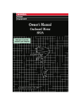
This manual covers operation and maintenance of EM5000SX/EM5000X
generators. All information
in this publication
is based on the latest product
information
available at the time of approval for printing.
Honda Motor Co., Ltd. reserves the right to make changes at any time.without
notice and without incurring any obligation.
No part of this publication
may be reproduced. without
This manual should be considered a permanent
main with the generator when sold.
Pay special attention
to statements
m
Indicates a strong possibility
life if instructions are not followed.
NOTE:
Indicates a possibility
are not followed.
Gives helpful
injury
or death
of severe personal
of personal
permission.
part of the generator,and
preceded by the following
ADANGER:
Indicates severe personal
structions are not followed.
CAUTION:
instructions
written
re
words:
will
result
if in-
injury
or loss of
injury or equipment
damage if
information.
If a problem should arise, or if you have any questions
consult an authorized Honda dealer.
about the generator,
m
The Honda generator is designed to give safe and dependable service if operated according to instructions.
Read and understand this Owner’s
Manual before operating the generator. Failure to do so could result in personal injury or equipment damage.
NOTE:
This generator is equipped with a U.S.D.A. qualified spark arrester
which requires periodic maintenance to ensure its effectiveness. It is illegal in
some areas to operate an engine without
a spark arrester. Check local laws
and regulations.
1
CONTENTS
.’
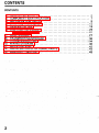
CONTENTS
3.
4.
5.
6.
7.
8.
9.
10.
11.
12.
13..
GENERATOR’SAFETY:.
..................................
COMPONENT
IDENTIFICATION
............................
PRE-OPERATION
CHECK .....
: .............................
STARTING
THE ENGINE ..................................
GENERATOR
USE. ......................................
STOPPING THE ENGINE ...................................
l High altitude operation
;. ......................
...........
MAINTENANCE..........................................2
; .............
TRANSPORTING/STORAGE
.................
TROUBLESHOOTING.
...................................
WIRING DIAGRAM.......................................4
SPECIFICATIONS......‘..................................4
INSTALLATION
OF OPTIONAL
PARTS .....................
WARRANTY
FERVICE .......................................
’
.:.
2
: ;.
.,:
3
7
9
.13
.18
.25
.26
7
.36
~38’
0
2
.43
.49
1.
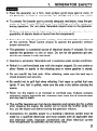
GENERATOR
SAFETY
l
Place the generator on a firm, level surface; avoid loose sand or snow. If
the generator is tilted or overturned,
fuel spillage and a fire may result.
l
To prevent fire hazards and to provide adequate ventilation,
keep the generator at least 1 meter (3 feet) -away from buildings and other equipment
during operation.
Do not place flammable objects close to the generator.
l
Children and pets must be kept away from the area of operation
possibility of electric shock or burns from hot components.
l
Know how to stop the generator quickly, and understand the operation of
all the controls.
Never permit anyone to operate the generator without
proper instruction.
l
The generator is a potential source of electrical shocks if misused. Do not
operate the generator in rain or snow. Do not let the generator get wet,
and do not operate it with wet hands.
0 Gasoline
is extremely
flammable
and is explosive
due to a
under certain conditions.
l
Refuel in a well-ventilated
area with the engine stopped. Do not smoke or
allow flames or sparks in the refueling area or where gasoline is stored.
l
Do not overfill
closed properly
l
Be careful not to spill fuel when refueling. Fuel vapor or spilled fuel may
ignite. If any fuel is spilled, make sure the area is dry before starting the
engine.
l
Never run the engine in an enclosed or confined area. Exhaust contains
poisonous carbon monoxide gas; exposure may cause loss of consciousness
and may lead to death.
l
The muffler becomes very hot during operation and remains hot for a while
after stopping the engine. Be careful not to touch the muffler while it is
hot. Let the engine cool before storing the generator indoors.
l
Connections
for standby power to a building’s electrical system must be
made by a qualified electrician
and must comply with all applicable laws
and electrical
codes. Improper connections
can allow electrical
current
from the generator to backfeed into the utility lines.
the fuel tank.
and securely.
After
refueling,
make sure the tank cap is
3
Such backfeed may electrocut6
utility company workers or others who
contact the lines during a power outage, and when utility power is restored,
the generator may explode, burn, or cause fires in the building’s electrical
system.
CAUTION:
Equipment damage and corrosion from sand, dirt, and water may
occur if the generator is overturned or sinks into a soft surface.
‘4
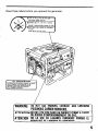
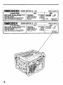
Read these labels before you operate the generator.
/
FWARNING
DO NOT USE INDOORS.EXHAUST GAS CDNTAlNS>
POISONOUSCARBONMONOXIDE.
ATTENTION NE,PASUTlLlSERDANSUNENDROlT FERMEACAUSE
DU RISQUED'EMPOISONNEMENTDU GAZ.
ATENCl(')N NO LO USE EN LUGARES CERRADOS PORQUEEL
MONOXIDEDE CARBON0 ESVENENOSO.
\
//
5
? CO.. LTD.
EM5000X
-
IAl.
CAUTLUN
6
MADE IN JAPAN Gl
HONDA MOTOR CO., LTD.
II
II
am
AL
II
II
MADE IN JAPAN @
Ah
Ub
1
II
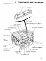
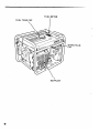
2.
COMPONENT
IDENTIFICATION
ENGINE SWITCH (EM5000X)
PILOT LAMP
-.lYlL,Lrl
.‘\’ I
VOLT R/lCl-CD
OIL ALERT
VOLTAGE
SELECTOR
SWITCH
LAMP
ENGINE SWITCH
CHOKE ROD
\
1,\
\
\
\I
\
FUEL VALVE
AIR
CLEANER
:EPTACLES
RECOIL
STARTER
GRIP
TERMINAL
DC CIRCUIT
PROTECTOR
OIL FILLER
DC OUTPUT
TERMINAL
CAP
SWITCH (EMSOOOSX)
OIL DRAIN
PLUG
7
FUEL TANK CAP
FUEL METER
I
SPARK PLUG
CAP
MUFFLER
i
8
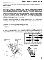
3.
Perform the pre-operation
engine stopped.
PRE-OPERATION
CHECK
check with the generator on a level surface and the
i’
,
1. Engine Oil
CAUTION:
Engine oil is a major factor affecting engine performance and
service life. Non detergent oils, ‘castor-based oils, and 2-stroke engine dils are
not recommended
because they have inadequate lubrictitihg
characteris!ics.
Use Honda 4-stroke oil an equivalent high-detergent,
premium quality motor
oil certified to meet or exceed U.S. automobil
manufacture’s.requirements
for Service Classification
SG-SF/CC-CD.
Motor oils classified SG.SF/CCCD
will show this designation on the container,
SAE lOW/30 is recommended for general, all-temperature
use. Other viscosities shown in the chart may be used when the average temperature
in your
area is within the indicated range.
)
,. :
.’
, ”
1. Remove the oil filler cap and check the oil level.
,
2. ,lf the. level is low, fill to the top of the oil filler,neck
with the recornmel
nded oil.
.,
I:
NOTE: The Oil Alert System will automatically
stop the engine before the
oil level fails below the safe limit. However,.to avoid the inconvenie,nce of an
unexpected shutdown, it is advisable,to visually inspect the oil level regularly.
OIL FILLER
CAP
OIL FILLER
HOLE
-20
-30
,o
-20
, 20
-10.
40
0
Ambient
60
10
20
temperature
80
30
lOOoF
4o”c
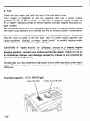
2. Fuel
Check the fuel meter and refill the tank if the fuel level is low.
Your engine is designed to use any gasoline that has a pump octane
number (-1
of 86 or higher, or that has a research octane number of
91 or higher. Gasoline pumps at service station normally display the pump octane number.
We recommend that you use unleaded fuel because it produces fewer engine
and spark plug deposits and extends the life of exhaust system components.
Never use stale or contaminated gasoline or an oil/gasoline mixture. Avoid getting dirt, dust or water in the fuel tank. Use of a lower octane gasoline can
cause persistent “pinging”
or heavy “spark knock” (a metallic rapping noise)
which, if severe, can lead to engine damage.
CAUTION:
If “spark
knock”
or “pinging”
occurs at a steady engine
speed under normal load, change brands of gasoline.
If spark-knock
or
pinging persists, consult your authorized
Honda dealer. Failure to do so
is considered
misuse, and damage caused by misuse is not covered by
Honda’s Limited Warranty.
Occasionally you may exp’erience light spark knock while operating under heavy
loads. This is no cause for concern, it simply means your engine is operating
efficiently.
Fuel tank capacity:
17.0 II (4.5 US gal)
FUEL METER
10
FUEL FILLER
CAP
‘m
,:
l
I
~
i
’ Gasoline
is extremely
.flammable
and is explosive
under certain
conditions.
l
Refuel in a well-ventilated
area with the engine stopped.
Do not
smoke or allow flames or sparks in the area where the engine is refuel-’
’
ed- or where .gasoline is stored.
l
Do not overfill the fuel tank (there should be no fuel in the filler neck).
After
refueling,
make sure the tank cap is closed properly
and
securely.
l
Be careful not to,spill fuel when refueling.
Spilled fuel or fuel vapor
may ignite. If any fuel is spilled, make sure the area is dry before starting, the engine.
0 Avoid repeated or prolonged
contact with skin or breathing
of vapor.
KEEP OUT OF .REACH OF CHILDREN.
GASOLINES
CONTAINING
ALCOHOL
If you’decide to use a gasoline containing alcohol (gasohol), be sure it’s octane
rating is at least as high as that recommended by Honda. There are two types
of “gasohol”:
one containing ethanol, and the other containing methanol. Do
not use gasohol that contains more than 10% ethanol. Do not use gasoline
containing
methanol .(methyl or wood alcohol) that does not also contain
cosolvents and corrosion inhibitors for methanol. Never use gasoline containing
more than 5% methanol, even if it has cosolvents and corrosion’ inhibitors.
NOTE:
Fuel system damage or engine performance problems resulting from the use
of fuels that contain alcohol is not covered under the warranty. Honda cannot endorse the use of fuels containing methanol since evidence of their
suitability is as yet incomplete.
l
Before buying fuel from an unfamiliar station, try to find out if the fuel contains alcohol, if it ,does, ‘confirm the type and percentage of alcohol used.
If you notice any undersirable operating symptoms while using a gasoline
that contains alcohol, or one that you think contains alcohol, switch to a
gasoline that you know does not contain alcohol.
l
11
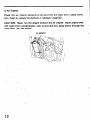
3. Air Cleaner
Check the air cleaner elements to be sure they are clean and in good condition. Clean or replace the elements if necessary (page30).
CAUTION:
Never run the engine without the air cleaner. Rapid engine wear
will result from contaminants,
such as dust and dirt, being drawn through the
carburetor, into the engine.
ELEMENT
.’
. .
.,
”
12
r
e
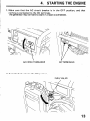
4.
STARTING
THE ENGINE
1. Make sure that the AC circuit breaker is. in the OFF position,
nothing is connected to the DC terminals.
The generator may be hard to start if a load is connected.
AC ClkUlT
BREAKER
DC TERM’IidALS
2. Turn the fuel valve to the ON position.
FUEL VALVE
and that
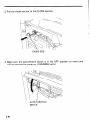
3. Pull the choke rod out td the CLOSE position.
CHOKE ROD
4. Make sure the auto-throttle
switch is’ in the.O.FF
will be required for warm up. (ERi15000SX only)
AU’TO-TH ROTTLE
SW I’TCH
‘14
position,
or more time
I,
:
.,
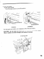
5. Start the engine
l With recoil starter:
Turn the engine switch to the ON position.
ITCH
I,
.,
\y
ENGINE SWITCH
(EM5000SXI
(EM5000X)
Pull the starter grip lightly
until resistance is felt, then pull briskly.
CAUTION:
Do not allow the starter grip to snap back against the engine.
Return it gently to prevent damage to the starter or housing.
.STARTER
GRIP
15
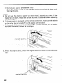
l
With electric starter (EM5000SX only):
Turn the engine switch to the START
the engine starts.
position
and hold it there until
NOTE:
Do not use the electric starter for more than 5 seconds at a time. If the
engine fails to start, release the switch and wait 10 seconds before operating
the starter again.
l If the generator is equipped with a remote control
kit, make sure the switch
on the relay box is turned off, or the engine will not start.
0 If the speed of the starter motor drops after a period of time, it is an indication that the battery.should
be recharged.
l
,ENGlNE SWITCH
;
6. When the engine starts, allow the engine switch
tion.
16
to return
to the ON posi-
‘I
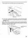
7. Push the choke rod to the OPEN position
CHdKE
as the engine warms up.
RQD
8. If you wish to use the auto-throttle
system, turn the auto-throttle
switch
to the AUTO position after the engine has warmed up for 2 or 3 minutes.
(EM5000SX only)
NOTE: When a battery is connected for electric starting, choke operation is
automatic, but you can override the automatic choke by manually pulling the
choke rod. If the choke is closed manually, you must also push in the choke
rod manually to allow the choke to open.
:
AUTO-THROTTLE
SWITCH
17
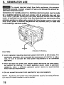
5.
GENERATOR
USE
m
To prevent electrical shock from faulty appliances, the generator
should be grounded. Connect a length of heavy wire between.the ground terminal and the ground source.
Connections
for standby power to a building’s electrical system must be made
by a qualified
electrician’ and must comply with all applicable laws and electrical codes. Improper connections
can allow electrical current from the generator to backfeed into the utility lines. Such backfeed may electrocute utility
company workers or others who contact the lines during a power outage, and
when utility power is restored, the generator may explode, burn, or cause fires
in the building’s electrical s
s
CL
.
CAUTION:
GROUNdTERillNiL
l
Limit operation requiring maximum power (5.0 kVA). to 30 minutes. For
continuous
operation, do not exceed the rated power of 4.5 kVA. In either
case, be sure to consider the total power requirements
of all connected
appliances.
l
Most appliance and power tool motors require more than the rated,operating current for start-up. To match appliance“power
needs to generator
capability,
allow a sufficient
generator power reserve to ‘accommodate
motor start-up requirements.
-z
0 Do not exceed the current
limit specified
for any one receptacle.
NOTE:
Appliance and power tool manufacturers
tion near the model number or serial number.
18
usually
list rating informa-
i
Oil Alert System
The Oil Alert system is designed to prevent engine damage caused by an insufficient amount of oil in the crankcase. Before the oil level in the crankcase
falls below a safe limit, the Oil Alert system will automatically
shut down the
engine (the engine switch will remain in the ON position).
If the Oil Alert system shuts down the engine, the Oil Alert lamp will flash
when you operate the starter, and the engine will not run. If this occurs, add
engine oil (P. 9 1.
OIL ALERT
LAMP
19
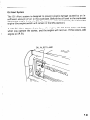
Auto-throttle
System (EM5000SX
only)
With .the switch in the-AUTO
position, engine speed is automatically
reduced
to an idle when all. loads are turned off or disconnected. When appliances are
turned cn or reconnected, the engine resumes the rated speed. At OFF, the
auto-throttle
system does not operate.
2:
NOTE:
q AUTO. is, recommended
to minimize fuel consumption
when no load is
applied.
l The auto-throttle
system will not respond to electrical loads of less than
1 ampere.
l The system is not-effective
for use with appliances that require only momentary power. To avoid extended warm-up periods, keep the switch OFF
until the engine reaches operating temperature.
AUTO-THROTTLE
SWITCH
20
I
AC applications
1. Start the engine and make sure the pilot
ment may be burnt out.
lamp comes on. If not, the fila-
2. Turn the voltage selector switch to either position
:
as required.
NOTE: With the voltage selector switch in the “12OV/24OV”
position, y.ou
can use the 120V and 240V receptacles simultaneously.
If you are not using
the 240V receptacle, but you require more power from the 120V twrst-lock
receptacle, then turn the switch to the “12OV” position.
VOLTAGE
SWITCH
PILOT
LtMP
3. Switch
on the AC Circuit
SELECTOR
Breaker.
AC CIRCUIT
BREAKER
21
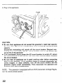
4. Plug in the appliance.
PLUG
CAUTION
0 Be sure that appliances do ‘not exceed the generator’s rated load capacity
for more than 30 .minutes and that they never exceed .the maximum load
capacity.
Substantial
overloading
will, switch off the circuit breaker. Marginal over.
loading may not switch off the circuit breaker, but it will shorten the
service life of the generator.
0 If an overloaded circuit causes the AC circuit breaker to switch off, reduce
the electrical load on. the ckcuit, and wait a few minutes before resetting
the circuit breaker.
l Be sure that all appliances
are in good working order before connecting
them to the generator. If an appliance begins to operate abnormally,
becomes sluggish, or stops suddenly, turn off the circuit breaker and the
generator engine switch immediately.
Then disconnect the appliance and
examine it for signs of malfunction.
NOTE:
This generator,is equipped
tor) for stable voltage supply.
22
with an AVR
(Automatic
Voltage
Regula-
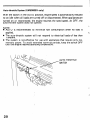
DC operation
The DC terminals
only.
may be used for charging
12 volt automotive-type
batteries
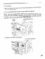
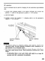
1. Connect both charging cables to the battery terminals and connect
positive (+ 1 cable to the generator’s positive (+ 1 DC terminal.
?
the
2. Start the engine.
i
3. Carefully connect the negative
negative (-1 DC terminal.
(- 1 charging
cable to to the generator’s
DC CIRCUIT
PROTECTOR
NEGATIVE TERMINAL
(BLACK)
l
l
POSITIVE TERMINAL
(RED)
The battery
gives off explosive
gases; keep
cigarettes
away. Provide adequate ventilation
ing batteries
in an enclosed
space.
The battery contains sulfuric
acid (electrolyte).
eyes may cause severe burns. Wear protective
shield.
- If electrolyte
gets on your skin, flush with
- If electrolyte
gets in your eyes, flush with
minutes and call a physician
immediately.
sparks,
flames
and
when charging
or usContact
clothing
with skin or
and a face
water.
water for at least
15
23
Electrolyte
is poisonous.
- If swallowed,
drink large quantities
of water or milk and follow
with milk of magnesia
or vegetable
oil and call a physician.
. KEEP OUT OF,REACH
OF CHILDREN.
0 To prevent the possibility
of creating a spark near the battery,
connect charging
cables first to the. battery,
then to the generator.
Disconnect
cables first at the generator.
l
Before connecting
charging
cables to a battery that is installed
in a
vehicle, disconnect
the vehicle’s
grounded
battery cable. Reconnect
‘the vehicle’s
grounded
.battery cable after the charging
cables are
removed. This procedure
will prevent the possibility
of a short circuit
and sparks if you make accidental
contact
between
a battery terminal and the vehicle’s
frame or body.
l
Never lean over the battery when making connections.
l
Never attempt
to charge a frozen battery. The battery could rupture
and explode. If you suspect that a battery may be frozen, remove the
vent caps and check the f!uid. If there seems to be no fluid, or if you
see ice, do not attempt
to charge the battery until the fluid thaws.
l
CAUTION:
Be careful to connect the,charging
cables to the correct battery and
generator
terminals
(positive to positive and negative to negative).
If
the charging
cables are connected
positive to negative,
it may cause
serious battery or generator
damage.
l
Do not attempt to start an automobile
engine with the generator
still
connected
to the battery;
this may damage the generator.
l
NOTE:
The DC terminals may be used while the AC power is in use.
An overloaded DC circuit will trip the DC circuit protector (push button
comes out). If this happens, wait a few minutes before pushing the circuit
protector to resume operation.
l
l
24
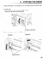
6.
To stop the engine in an emergency,
tion.
STOPPING
THE ENGINE
turn the ehgine switch to.the OFF posi-
In normal use:
1. Turn the AC circuit breaker to the OFF position.
Disconnect DC battery charging cables.
AC ~RCUIT
BREAKER
2. Turn the engine switch to the OFF position.
(EM5000SX)
(EM5000X)
ENGINE SWITCH
25
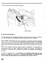
3; Turn the fuel valve to the OFF position.
.
l
High altitude
.
FUEL VALVE
operation
At high altitude,
rich. Performance
the standard carburetor air-fuel mixture will be excessively
will descrease, and fuel consumption
will increase.
High altitude performance
can be improved by installing a smaller diameter
main fuel jet in the carburetor and readjusting the pilot screw. If you always
operate the Generator at altitudes higher than 6,000 feet above sea level, have
your authorized
Honda Generator dealer perform these carburetor modifications.
Even with suitable carburetor jetting, engine horsepower will descrease approximately
3.5% for each 1,000 foot increase in altitude.
The affect of
altitude on horsepower will be greater than this if no carburetor.modification
is made.
CAUTlON:
Operation
of the Generator at an altitude lower than the carburetor is jetted foi- may result in reduced performance,
overheating,
and
serious engine damage caked ‘by an excessively lean air/fuel mixture.
26
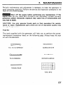
7.
MAINTENANCE
Periodic maintenance and adjustment is necessary to keep the generator, in
good operating condition. Perform the service and inspection scheduled in the
table on the following page.
m.
Shut off the engine before performing
any maintenance.
If the
engine must be run, make sure the area is well ventilated.
Exhaust contains
poisonous carbon monoxide;
exposure may cause loss of consciousness and
may lead to death.
CAUTION:
Use only genuine Honda parts or their equivalent
nance or repair. Replacement parts which are not of equivalent
damage the generator.
for maintequality may
Tool Kit
The tools supplied with
maintenance procedures
kit with the generator.
the generator will help you to perform the ownerlisted on the following
page. Always keep this tool
D
10 x 12 mm WRENCH
1
SCREW DRIVER’
: .,
PLUG WRENCH
HANDLE
DRIVER
>
HANDLE
BAR
TOOL BAG
27
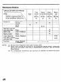
Maintenance
Schedule
Each
use
~~~
First
month
20’Lrs.
(3)
Engine oil
Air cleaner
Check level
Change
Check
Clean
Sediment cup and
Clean
fuel valve filter
Soark olug
Clean-Readjust
Soark arrester
Valve clearance
Clean
Check-Readiust
Fuel tank, strainer,Clean
and tank filter
Check (Replace
Fuel line
if necessary)
NOTE:
28
Every 3 years (2)
(1) Service more frequently when used in dusty areas.
(2) These items should be serviced by an authorized Honda dealer, unless the
owner has the proper tools and is mechanically proficient. See the Honda
Shop Manual.
(3) For professional commercial use, log hours of operation to determine proper
maintenance intervals.
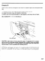
Changing Oil
Drain the oil while the engine is still warm to assure rapid and complete
ing.
drain-
1. Remove the oil filler cap and drain plug to drain the oil.
2. Install the drain plug, and tighten it securely.
3. Refill with the recommended oil (see page 9), and check the oil level.
OIL CAPACITY:
1.1 Q (1.16 US qt )
DRAIN
PLUG
CAUTION:
Used motor oil may cause skin cancer if repeatedly left in contact
with the skin for prolonged periods. Although this is unlikely unless you handle
used oil on a daily basis, it is still adviseable to thoroughly wash your hands with
soap and water as soon as possible after handling used oil.
NOTE: Please dispose of used motor oil in a manner that is compatible with the
environment. We suggest you take it in a sealed container to your local service
station for reclamation. Do not throw it in the trash or pour it on the ground.
29
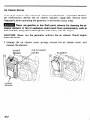
Air Cleaner Service
.
A dirty air cleaner will, restrict air flow to the carburetor. To prevent carburetor malfunction,
service the air cleaner regularly ,(page 28). Service more
frequently when operating the generator in extremely dusty areas.
m
Never use gasoline or low flash point solvents for .cleaning the air
cleaner element. A fire or explosion could’ result from contaminants,
such as
dust and dirt, being drawn through the carburetor, into the engine.
CAUTION:
Never
wear will result.
run the generator
1. Unsnap the air cleaner
remove the element.
COVER
without
cover springs,
AIR
the air cleaner.
remove the air cleaner
CLEANER
ELEMENT
COVER
SPRING
30
‘.
Rapid
engine
cover, and
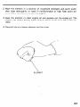
2. Wash the element in a solution of household detergent and warin water,
then rinse thoroughly,
or wash in nonflammable
or high flash point sol,vent. Allow the element to dry thoroughly.
3. Soak the element in clean engine oil and squeeze out the excess oil. The
engine will smoke during initial start-up if too much oil is left in the element.
4. Reinstall
the air cleaner element and the cover.
ELEMENT
31
Sediment
Cup and Filter Cleaning
The sediment cup and filter prevent dirt or water which may be in the fuel
tank from entering the carburetor.
If the engine has not been run for a long
time, the sediment cup and filter should be cleaned.
1. Turn the fuel valve to the OFF position. Remove the sediment cup, O-ring,
and filter.
2. Clean the sediment cup, O-ring, and filter in nonflammable
or high flash
point solvent.
3. Reinstall the filter, O-ring, and sediment cup.
l
l
Gasoline
After
is extremely
installing
area is dry
flammable
the sediment
before
starting
and is explosive
under certain conditions.
cup, check for fuel leaks, and make sure the
the engine.
Fuel vapor
or spilled
FUEL VALVE
CUP
FUEL
FILTER
0
32
SEDIMENT
/
CUP
-O-RING
fuel may
ignite.
Spark Plug Service
Recommended
I
spark plug:
BPR5ES (NGK)
WlGEPR-U (ND)
To ensure proper engine operation,
and free of deposits.
the spark plug must be properly
m
If the engine has been running, the muffler
careful not to touch the muffler while it is hot.
will
gapped
be very hot. Be
1. Remove the spark plug cap.
2. Clean any dirt from around the spark plug base.
3. Use the wrench
supplied
in the tool
kit to remove
the spark
plug.
4. Visually
inspect the spark plug. Discard it if the insulator is cracked or
chipped. Clean the spark plug with a wire brush if it is to be reused.
5. Measure the plug gap with a feeler gauge. The.gap should be 0.7-0.8 mm
(0.028-0.031
in).
0.7-0.8 mm
(0.028-0.031
in)
33
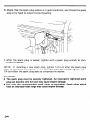
6. Check that the spark plug washer is in good condition,
plug in by hand to prevent cross-threading.
7. After the spark plug is seated, ,tighten
press the washer.
with
and thread the spark
a spark plug wrench
to com-
NOTE:
If installing a new spark plug, tighten l/2 turn after the spark plug
seats to compress the washer. I,f. reinstalling a used spark plug,. tighten l/81/4 turn after the spark plug seats to compress the washer.
CAUTION:
The spark plug must be securely tightened. An impropefly
tightened spark
plug can become very hot and-may cause engine damage.
0. Use only the recommended
spark plugs or equivalent. Spark plugs which
have an improper heat range may cause engine damage.
l
34
I
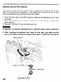
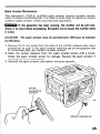
Spark Arrester
Maintenance
This generator’s U.S.D.A., qualified spark arrester requires periodic maintenance to ensure’ its effectiveness. It is illegal in some areas to operate an engine
without a spark arrester. Check local laws and regulations.
m
If the generator has been running, the muffler will be very hot.
Allow it to cool before proceeding. Be careful not to touch the muffler while
it is hot.
CAUTION:
its efficiency.
The spark arrester must be serviced every 100 hours to maintain
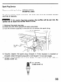
1. Remove the 4 mm screw from the side of the muffler exhaust pipe. Use a
screwdriver to push in the spark arrester retaining tab on the opposite side
of the exhaust pipe, and remove the spark arrester.
2. Clean the carbon deposits from the spark arrester screen with a brush.
Check .the spark arrester screen for damage. Replace the spark arrester if
the screen is torn or punctured.
3. Reinstall the spark arrester, and tighten the screw securely.
ARRESTER
/
SPARK ARRESTER
35
8.
l
l
TRANSPORTING/STORAGE
Let the engine cool before transporting
the generator or storing it indoors.
When,transporting
the generator, turn the engine switch and the fuel valve
to the OFF position, and keep the generator level to prevent fuel spillage.
Fuel vapor or spilled fuel may ignite.
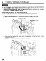
Before storing the unit for an extended period:
1. Be sure the storage area is free of excessive humidity and dust.
2. Drain the fuel a. With the fuel valve OFF, remove and empty the sediment cup.
FUEL VALVE
SEDIMENT
b. Turn the fuel valve ON, and drain the gasoline
suitable container.
c. Replace the sediment cup and tighten securely.
36
CUP
in the fuel tank into a
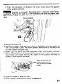
d. Drain the carburetor by loosening
into a suitable container.
the drain
screw. Drain the gasoline
m
Gasoline is extremely
flammable and is explosive under certain
conditions.
Perform this task in a well-ventilated
area with the, engine stopped. Do not smoke or allow flames or sparks in, the area during this procedure.
DRAIN SCREW
3. Change the engine oil.
4. Remove the spark plug, and pour about a tablespoon of clean engine oil
into the cylinder.
Crank the engine several revolutions
to distribute
the
oil, then reinstall the spark plug.
5. Slowly pull the starter grip until resistance is felt. At this point, the position is coming up on its compression stroke and both the intake and exhaust valves are closed. Storing the engine in this position will help to
protect it from ‘internal corrosion.
6. Cover the engine to keep out dust.
7. Once a month, recharge the battery.
(EM5000SX)
37
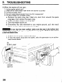
9.
TROUBLESHOOTING
A.When the engine will hot start:
1. Is the engine switch on?
,_
2. Does the oil alert lamp flash when the starter is pulled?
3. Is there enough fuel?
4. Are all loads disconnected from the AC receptacles?
5. Is there a spark atthe spark plug?
a. Remove the spark plug cap, Clean any dust from around the spark
plug base, then remove the spark plug.
b. Install the spark plug in the plug cap.
c.‘Turn the engine switch on.
d. Grounding
the side electrode to any engine ground, pull the recoil
starter to see if sparks jump across the gap.
m
If any fuel has been spilled, make sure the area is dry before testing the spark plug. Fuel vapor or spilled fuel may ignite. Perform this test in
a well-ventilated
area.
e. If there are no sparks, replace’the plug.
f. If the new spark plug does not spark, take the generator to an authorized Honda dealer.
OIL
ALERT
ENGINE
SWITCH
38
LAMP
I
I
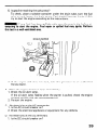
6. Is gasoline reaching the carburetor?
To check, place a suitable container under the drain tube, turn the fuel
valve on and loosen the drain screw. Fuel should flow out freely. If OK,
try to start the engine according to the instructions.
m
If any fuel has been spilled, make sure the are is dry before attempting to start the engine. Fuel vapor or spilled fuel may ignite. Perform
this test in a well-ventilated
area.
DRAINsSCREW
1.
/
.
7. If the engine still does not start, take the generator
Honda dealer.
B. When the engine starts but stops immediately;
1. Check the oil alert lamp.
If the oil alert lamp flaslies when the starter is pulled,
oil level and fill with the recommended oil.
2. Restart the engine.
C. No electricity at the AC receptacles:
1. Is the AC circuit breaker on?
2. Check the electrical appliance or equipment
to an authorized
check the engine
for any defects.
D. No electricity at the DC terminals.
1. Is the DC circuit breaker on?
39
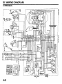
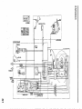
10. WIRING DIAGRAM
(‘EM5000SX)
3
-
..- _............
*,NOAozL-mz/mL
I
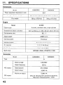
11.
SPECIFICATIONS
Dimensions
EM5000SX
Model
Power equipment
description
Length x Width’x
EM5000X
code
Height
Dry weight
EA7
655 x 510 x 490 mm (25.8 x 20.1 x 19.3 in)
80 kg (176.4 lb)
78 kg (171.9 lb)
Engine
GX340
Model
4-stroke, overhead valve, single cylinder
Engine type
Displacement
(Bore x Stroke)
337 cc (20.6 cu in) 182 x 64 mm (3.2 x 2.5 in)]
Compression ratio
8.0 : 1
Engine speed
3,600 r.p.m.
Cooling system
Forced air
Ignition system
Transistorized
magneto
Oil capacity
1.1 ]z (1.16 USqt)
Fuel tank capacity
17.0 Q (4.5 US gal)
Spark plug
IBPRSES (NGK), WlGEPR-U
(ND)
Generator
Model
:A
Type
Rated voltage
Rated frequency
AC output
DC output
42
EM5000X
EM5000SX
120/24OV
60 Hz
Rated ampere
37.5118.8A
Rated output
4,500 VA
Maximum
5,000 VA
ourtput
Only for charging 12V automotive batteries.
Maximum charging output = 8.3A
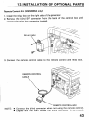
‘l2JNSTALLATION
Remote Control
Kit (EM5000SX
OF OPTIONAL
only)
1. Install the relay box on the right side of the generator.
2. Remove the blind 8-P connector from the back of the control
connect the relay box connector instead.
3. Connect
the remote
control
PARTS
cable to the remote control
box and
and relay box.
REMOTE CONTROL
CARI
F
’
NOTE:
l
l
REMOTE CONTROL
BOX
Connect the blind connector when not using the remote control.
Engine will not start unless the blind connector
is connected.
43
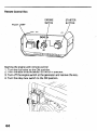
Remote Control Box
ENGINE
SWITCH
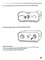
Starting
1. Turn
2. Turn
3. Turn
4. Turn
the
the
the
off
the
STARTER
BUTTON
engine with remote control
fuel valve to the ON position.
auto-throttle
switch to the OFF position.
the engine switch at the generator and remove the key.
relay box switch to the ON position.
5. Turn the engine switch at the remote control
6. Press the starter button
box to the ON position.
until the pilot lamp comes on.
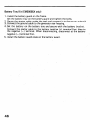
Stopping the engine
1. Turn the engine switch at the remote control box to the OFF position.
2. Turn the relay box switch to the OFF position.
3. Turn the fuel valve to the OFF position.
45
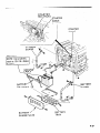
Battery
Tray Kit (EM!jOOOSX only)
1. Install the battery guard on the frame.
Set the battery tray on the battery guard and tighten the bolts.
2. Route the starter cab!e under the tank and connect it to the starter solenoid.
3. Connect the ground cable to the generator rear housing.
4. Set the battery on the battery tray and secure with the battery bracket.
Connect the starter cable to the battery positive (+) terminal first, then to
the negative (-) terminal. When disconnecting,
disconnect at the battery
negative (-) terminal first..
5. Install the battery guard plate on the battery guard.
_
STARTER
STARTER
lor more
\
CABLE
BATTERY
-GUARD
BATTERY /
GUARD PLATE
\
BATTERY
45
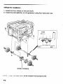
4-Wheel Kit Installation
1. Install the four wheels on the axle shaft.
2. Install the axle ak’mbly
on the generator
using four bolts and nuts.
Inside.
WHEEL! STOPPER
NOTE:
48
Install the shaft with wheel stopper facing engine side.
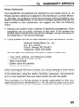
13.
WARRANTY
SERVICE
Owner Satisfaction
Your satisfaction
and goodwill
are important
to your dealer and to us. All
Honda warranty
details are explained in the Distributor’s
Limited Warranty. Normally, any problems concerning
the product will be handled by your
dealer’s service department.
If you have a warranty
problem that has not
been handled to your satisfaction,
we suggest you take the following
action:
l
l
Discuss your problem with a member of dealership management.
Often
complaints
can be quickly resolved at that level. If the problem has
already been reviewed with the Service Manager, contact the owner of
the dealership
or the General Manager.
If your problem
still has not been resolved
to your satisfaction,
contact:
American
Honda Motor Co., Inc.
P.O. Box 100021
Duluth, Georgia 30136-9421
Telephone:
(404) 497-6400
We will need the following
-.
-
information
Your name, address, and telephone
Product model and serial number
Date of purchase
Dealer name and address
Nature of the problem
in order to assist
you:
number
After reviewing
all the facts involved,
you will be advised of what action
can be taken. Please bear,in mind that your problem will likely be resolved
at the dealership,
using the dealer’s facilities,
equipment,
and personnel,
so it is very important
that your initial contact be with the dealer.
Your purchase
of a Honda product is greatly appreciated
by both your
dealer an’d American Honda Motor Co., Inc. We want to assist you in every
way possible to assure your complete satisfaction
with your purchase.
49
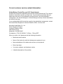
Current customer service contact information:
United States, Puerto Rico, and U.S. Virgin Islands:
Honda Power Equipment dealership personnel are trained professionals. They should
be able to answer any question you may have. If you encounter a problem that your
dealer does not solve to your satisfaction, please discuss it with the dealership's
management. The Service Manager or General Manager can help. Almost all problems
are solved in this way.
If you are dissatisfied with the decision made by the dealership's management, contact
the Honda Power Equipment Customer Relations Office. You can write:
American Honda Motor Co., Inc.
Power Equipment Division
Customer Relations Office
4900 Marconi Drive
Alpharetta, GA 30005-8847
Or telephone: (770) 497-6400 M-F, 8:30 am - 7:00 pm EST
When you write or call, please provide the following information:
•
Model and serial numbers
•
Name of the dealer who sold the Honda power equipment to you
•
Name and address of the dealer who services your equipment
•
Date of purchase
•
Your name, address, and telephone number
•
A detailed description of the problem
MEMO
50
MEMO
51
MEMO
52