1
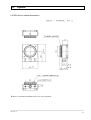
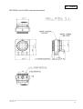
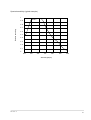
BE-IR20 / 21 Infrared B/W Camera Module Operation Guide Please read this operation Guide carefully for proper operation, and keep it for future refernce. Table of Contents 1. Introduction ・・・・・・・・・・・・・・・・・・・・・・・・・・・・・・・・・・・・・・・・・・・ 2 2. General ・・・・・・・・・・・・・・・・・・・・・・・・・・・・・・・・・・・・・・・・・・・・・・・ 2 3. Composition ・・・・・・・・・・・・・・・・・・・・・・・・・・・・・・・・・・・・・・・・・・・ 2 4. Specifications・・・・・・・・・・・・・・・・・・・・・・・・・・・・・・・・・・・・・・・・・・ 2 5. Notes to users ・・・・・・・・・・・・・・・・・・・・・・・・・・・・・・・・・・・・・・・・・ 4 6. External view ・・・・・・・・・・・・・・・・・・・・・・・・・・・・・・・・・・・・・・・・・・ 6 7. Optical dimensions ・・・・・・・・・・・・・・・・・・・・・・・・・・・・・・・・・・・・・ 6 8. Installation ・・・・・・・・・・・・・・・・・・・・・・・・・・・・・・・・・・・・・・・・・・・・ 7 9. Typical connection ・・・・・・・・・・・・・・・・・・・・・・・・・・・・・・・・・・・・・ 8 10. External sync (BE-IR21) ・・・・・・・・・・・・・・・・・・・・・・・・・・・・・・・・ 10 11. Function settings and changes 11-1 AGC on / off ・・・・・・・・・・・・・・・・・・・・・・・・・・・・・・・・・・・・・・ 12 11-2 Gamma response ・・・・・・・・・・・・・・・・・・・・・・・・・・・・・・・・・ 13 11-3 Auto electronic shutter on / off ・・・・・・・・・・・・・・・・・・・・・・ 14 11-4 Changes to fixed shutter mode ・・・・・・・・・・・・・・・・・・・・・・ 15 11-5 BE-IR20 external sync ・・・・・・・・・・・・・・・・・・・・・・・・・・・・・ 16 11-6 BE-IR21 internal sync ・・・・・・・・・・・・・・・・・・・・・・・・・・・・・・ 17 11-7 HD and VD output (BE-IR20 only) ・・・・・・・・・・・・・・・・・・・ 18 12. Options Mount adapter LA-IR20 ・・・・・・・・・・・・・・・・・・・・・・・・・・・・・・・・・・ 19 Attachment : Spectral sensitivity characteristic ・・・・・・・・・・・・・・・ 21 BE-IR20 / 21 1 1. Introduction Thank you very much for your purchase of the Hitachi BE-IR20/21 Black and White Camera Module. Prior to using this camera , read this manual carefully. 2. General The Hitachi BE-IR20/21 are black and white camera modules using a 1/4 inch interline CCD. The BE-IR20/21 are so small that they are most suitable for use with the equipment provided with limited space. BE-IR20 : Internal sync BE-IR21 : External sync 3. Composition 1) Black and white camera module ・・・・・・・・・・・・・・・・・・ 1 2) Interface cable ・・・・・・・・・・・・・・・・・・・・・・・・・・・・・・・・・ 1 Note : The standard accessory cable is 300 mm signal conductor. Different length cable requires shielding to avoid external noise. 4. Specifications 1) Imaging device No. of pixels 1/2 inch interline CCD EIA : 811(H)×508(V) CCIR : 795(H)×596(V) No. of effective pixels EIA : 768(H)×494(V) CCIR : 752(H)×582 Pixel pitch EIA : 8.4(H)×9.8(v)µm CCIR : 8.6(H)×8.3(V)µm 2) Sensing area EIA : 6.45(H)×4.84(V)mm CCIR : 6.47(H)×4.83(V)mm 3) Signal format Conforming to EIA or CCIR. 4) Scanning system 2:1 interlaced 5) Hor. scanning frequency EIA : 15.734 kHz CCIR : 15.625 kHz 6) Vert. scanning frequency EIA : 59.94 Hz CCIR : 50 Hz 7) Sync system BE-IR20 : Internal sync BE-IR21 : External sync BE-IR20 / 21 2 4. .Specifications 8) External sync input HD & VD : 5V peak-to-peak negative Input impedance : 1kΩ Frequency deviation : ±1% 9) Video output 1.0 Vp-p, 75Ω, unbalanced Video component : 0.7 Vp-p Sync component : 0.3 Vp-p negative 10) Resolution EIA : 570(H)×380(V) TV lines CCIR : 560(H)×380(V) TV lines 11) Signal to noise ratio 56 dB 12) Auto electronic shutter Provided (factory setting OFF) 13) Automatic gain control (AGC) Max. 32 dB approx. Fixed gain(factory setting) 14) Integration mode Field integration mode 15) Gamma correction 0.45 ON (factory setting) or OFF Selected by changing chip parts 16) Sensitivity 30 lux , F4, 3200k 17) Minimum illumination 0.3 lux , F1.4 , AGC and gamma on 18) Power supply voltage 9 ± 0.5 VDC 19) Power consumption Approx. 160mA 8) Operating : -5 to 45℃ , 90% RH or less Ambient conditions Storage : -10 to 60℃ , 70% RH or less 21) External dimensions 34(W)×34(H)×20(D) mm 22) Mass Approx. 17 grams (w/o cable) 23) Options Mount adaptor LA-IR20 BE-IR20 / 21 3 5. Notes to users Power supply z Connect a 9V DC voltage (8.5 to 9.5V) from an external regulated DC power supply. z Use a stable power supply without ripple and noise. z Prior to turning on the power switch , check that the polarities of the power cable are correct , referring to the connection diagram (Page 8 , 9) To protect CCD (sensor) z Do not touch the glass surface of the CCD sensor to avoid deterioration in picture quality due to dirt and scratches. z If the glass surface of the sensor should become dusty or dirty , remove dust or dirt carefully with a cotton-tipped applicator. Do not wipe the surface with dry cloth or paper tissue to avoid possible damage to the glass surface by static electricity. Protection of camera z Do not use or store the camera under direct sunlight , at a place exposed to rain or snow , or at a place where flammable or corrosive gas is present. z When housing the camera in a camera case , use the utmost care regarding rise of internal temperature. When casing the camera , the temperature normally rises by 10 to 20℃ , compared with the outside air temperature. The camera operates in the temperature range from -5 to 45℃. If the camera is used or left in high temperature environment for hours , the life of the camera may be shortened. z Do not drop the camera. Do not apply strong shock or vibration to the camera. z Before connecting or disconnecting a connector , turn off the camera and be sure to hold connector body to connect or disconnect the connector. Camera arrangement z Mutual interference noise can occur if multiple cameras are arranged in close proximity. Separate the cameras to the extent possible. When camera units are installed directly into other equipment , external noise can prevent a normal picture. In such cases , shield the camera units. The camera can be damaged by static electricity. Use ample care when installing and arranging. Auto electric shutter z In regions using 50 Hz power line frequency , flicker can appear on the monitor screen from light sources such as fluorescent or mercury. In such cases , release the auto electronic shutter. BE-IR20 / 21 4 5. Notes to users Phenomena inherent to CCD imaging device Following are phenomena inherent to a CCD imaging device , and not defects. z Smear and blooming When strong light (lamp , fluorescent lamp , reflected light , etc.) is shot , pale bands are displayed vertically above and below the light. In this case , change the angle of the camera so that such strong light does not enter the camera through the lens. z Fixed pattern noise When the camera is operated in a high temperature , fixed pattern noise may appear on the entire screen. The higher the sensitivity of camera , the more this fixed pattern noise appears. z Moire When fine patterns are shot , moire may be displayed. z The CE mark is required when exporting to Europe. Obtain the necessary authorization for the customer’s system. Enclose the camera in a shielded case and use shielded cable. BE-IR20 / 21 5 6. External view Dimensions 7. Optical dimensions Lens Lens-mount 19.2 ± 0.5 (C-mount) Extension of optical path due to the thickness of CCD glass is considered. CCD 1.4 ± 0.2 Base plate Imaging face BE-IR20 / 21 6 8. Installation When installing the camera in a housing or unit of equipment, secure with two M2 screws inserted into the 2.5 mm diameters holes of the SENS board base plate. Two 2.5 mm Dia. SENS board 1. Use the SENS board holds to install the camera. Avoid using only the Main board, Notes : due to risk of damage to the board connector. 2. Avoid unnecessary stress on the printed board when engaging and disengaging the connectors. 3. The screws securing the base plate and SENS board protrude a maximum of 2 mm from the base plate. Observe these screws do not contact the housing or installed equipment. BE-IR20 / 21 7 9. Typical connection BE-IR20 Connector B7B-ZR Image processor or Video monitor IN VIDEO OUT 75Ω ON OFF Housing ZHR-7 N.C N.C N.C +9V GND Video OUT Video GND 7 6 5 4 3 2 1 (Note 1) BLK GRN YEL Regulated power supply (More then 300 mA) RED Note1 : • When more than one video monitor is connected in series , set the 75Ω termination switch on the last unit − + to ON. Note2 : • Supply voltage range : 8.5 to 9.5V • Be sure to check the polarities of the power source DC9V (Note 2) before turning on the external DC power supply. BE-IR20 / 21 8 9. Typical connection BE-IR21 Connector B7B-ZR Image processor or Video monitor IN VIDEO OUT 75Ω ON OFF Housing ZHR-7 GND V.D H.D +9V GND Video OUT Video GND 7 6 5 4 3 2 1 (Note 1) BLK GRN YEL Regulated power supply (More then 300 mA) RED HD VD GND External sync signal − + Note1 : • When more than one video monitor is connected in series , set the 75Ω termination switch on the last unit to ON. DC9V (Note 2) Note2 : • Supply voltage range : 8.5 to 9.5V • Be sure to check the polarities of the power source before turning on the external DC power supply. BE-IR20 / 21 9 10. External sync (BE-IR21) Supply sync signals (HD and VD) for BE-IR21 operation. Refer to connection on page 9. z z z Horizontal and vertical drive signal inputs HD EIA: f(H) = 15.734 kHz ±1 % VD EIA: f(V) = 59.94 Hz (f(V) = f(H) ÷ 262.5) Input level HD 4 to 6 Vp-p negative VD 4 to 6 Vp-p negative Input impedance 1 kΩ z Drive signal input waveform z Horizontal drive signal (HD) T=1/f(H) z Vertical drive signal (VD) T=1/f(V) 4∼6Vp-p 4∼6Vp-p Approx. 6.7µs Approx. 0.6ms z HD and VD phase relationship VD Set HD and VD fallings edges to the same phase (0 ± 5 µs) HD BE-IR20 / 21 10 11. Function setting and changes When changing the function settings , perform the work with thorough care. Be sure to use anti-static measures such as a grounding band. Also observe safety precautions when soldering to avoid burn and fire hazards. Hitachi Denshi assumes on liability for damage or injury resulting from such work. Since the function setting can be provided at the time of shipment , consult a Hitachi Denshi representative. 11-1 AGC on / off Factory setting is AGC off (fixed gain). If necessary in the application, AGC can be set to on. When the AGC is off, the gain can be changed by turning RV201. Set AGC on by changing the indicated chip parts. Gain R211 R212 fixed gain 0Ω Absent AGC Remove 0Ω Factory setting Location of chip resistor (Main board side A) BE-IR20 / 21 11 11. 11-2 Function setting and changes Gamma response The factory setting is gamma on. If necessary , the gamma response can be changed as follows. Change the gamma response by changing the chip part. Gamma(γ)response R217 R218 R219 ON Absent 0Ω 0Ω OFF 0Ω Remove Remove 0Ω : Part code Description Factory setting RME1784 ERJ3GEYJ0R00V Location of chip capacitors (Main board side B) BE-IR20 / 21 12 11. 11-3 Function setting and changes Auto electronic shutter on / off Factory setting for auto electronic shutter is off. If necessary , it can be set to on. Absent the R259 , R260 chip to set the auto electronic shutter to on. Auto electronic shutter R259 R260 OFF 0Ω 0Ω ON Absent Absent 0Ω : Part code Description Factory setting RME2068 ERJ2GE0R00X Location of chip resistors (Main board side B) BE-IR20 / 21 13 11. 11-4 Function setting and changes Changes to fixed shutter mode The fixed shutter mode can be changed by replacing the chip parts indicated below. Mode R259 R260 R261 R262 R263 R264 R265 R266 R267 R268 R269 Normal mode 0Ω 0Ω Absent 0Ω Absent 6800 10k 27k 10k 10k 27k Auto electronic Remove Remove Absent shutter mode 0Ω Absent ↑ ↑ ↑ ↑ ↑ ↑ Remove Absent 0Ω 0Ω Remove 0Ω 0Ω Remove ↑ ↑ ↑ ↑ 0Ω ↑ ↑ ↑ ↑ ↑ ↑ ↑ Factory setting EIA 1/100 Remove 0Ω 0Ω 1/250 ↑ ↑ ↑ 1/500 ↑ ↑ 1/1000 ↑ ↑ CCIR Fixed shutter mode 1/120 Absent Remove ↑ 1/2000 0Ω 1/5000 ↑ 1/10000 ↑ ↑ Remove Absent Remove Remove ↑ Absent Remove ↑ 1/100000 R259 , R260 Others ↑ ↑ 0Ω 0Ω 0Ω ↑ 0Ω 0Ω Part code Description : 0Ω Part code Description : 0Ω 0Ω Remove Remove 0Ω 0Ω Remove 0Ω Remove Remove 0Ω 0Ω Remove 0Ω Remove Remove 0Ω 0Ω Remove Remove Remove 0Ω RME2068 ERJ2GE0R00X RME1784 ERJ3GEYJ0R00V (Main board side A) (Main board side B) Location of chip resistors BE-IR20 / 21 14 11. 11-5 Function setting and changes BE-IR20 external sync The BE-IR20 factory setting is for internal sync. If required, this can be changed to external sync by changing chip parts. Change the following chip parts for external sync operation. Sync system R280 R281 R282 R284 Internal 100 Ω Absent Absent 0Ω External Delete 0Ω 100 Ω Delete 0 Ω: 100 Ω: Part code RME1784 Type ERJ3GEYJ0R00V Part code RME1797 Type ERJ3GEYJ101V (Main board side A) Factory setting (Main board side B) Location of chip resistors BE-IR20 / 21 15 11. 11-6 Function setting and changes BE-IR21 internal sync The BE-IR21 factory setting is for external sync. If required, this can be changed to internal sync by changing chip parts. Change the following chip parts for internal sync operation. Sync system R280 R281 R282 R284 External Absent 0Ω 100 Ω Absent Internal 100 Ω Delete Delete 0Ω 0 Ω: 100 Ω: Part code RME1784 Type ERJ3GEYJ0R00V Part code RME1797 Type ERJ3GEYJ101V (Main board side A) Factory setting (Main board side B) Location of chip resistors BE-IR20 / 21 16 11. 11-7 Function setting and changes HD and VD output (BE-IR20 only) The BE-IR20 can be provided with horizontal and vertical drive outputs by changing chip parts. Change the following chip parts to provide HD and VD outputs. R233 R239 R240 R241 R242 Factory setting 0Ω Absent 0Ω Absent 0Ω Absent 0Ω Absent HD & VD output Delete 0Ω Delete 0Ω Delete 0Ω Delete 0Ω 0 Ω: Part code RME1784 Type ERJ3GEYJ0R00V R248 R249 R250 Connector pin assignments after change Pin No. Signal 1 Video out 2 Video GND 3 GND 4 +9V 5 HD out 6 VD out 7 HD/VD GND Note: The accessory cable cannot be used for signal outputs. Location of chip resistors(Main board side B) BE-IR20 / 21 17 12. Options LA-IR20 Mount adapter dimensions Remove c-mount attachment to use as cs-mount. BE-IR20 / 21 18 12. Options BE-IR20/21 and LA-IR20 combined dimensions BE-IR20 / 21 19 Spectral sensitivity (typical example) 1 0.9 0.8 Relative sensitivity 0.7 0.6 0.5 0.4 0.3 0.2 0.1 0 400 500 600 700 800 900 1000 Wavelength(nm) BE-IR20 / 21 20 Caution The specifications of this equipment are subject to change without notice for improvement. Prior to placing your order , be sure to confirm that these specifications are the latest ones. Hitachi Denshi guarantee that the equipment shipped from our factory conforms to the Hitachi Denshi’s standard warranty conditions and perform quality control within the range necessary to perform the warranty. Warranty and After-sales Service (1) The guarantee period is one year after the date of purchase. However , the defects due to erroneous use or intentional act are excluded. (2) As the defect after expiration of the guarantee period , Hitachi Denshi will repair the equipment if the intended function is restored by the repair work , and the cost is changed to a customer. (3) Hitachi Denshi is not liable for the losses caused when the equipment is used in a system used for business trades , production process , medical fields , crime prevention applications , etc. (4) The parts used in the equipment have their respective lives. The lives of such parts will be shortened under the environments of high temperature or high humidity. When the stable operation is required for a long time , it is recommended to perform periodical maintenance and inspection every year or every two years. Dec 27 2000 Jul 24 2000 Dec 9 1999 Aug 5 1999 BE-IR20 / 21 21