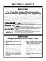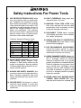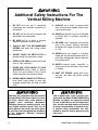
1
VERTICAL MILLING MACHINE
MODEL G1004/G1008
INSTRUCTION MANUAL
COPYRIGHT © 1999 BY GRIZZLY INDUSTRIAL, INC.
WARNING: NO PORTION OF THIS MANUAL MAY BE REPRODUCED IN ANY SHAPE
OR FORM WITHOUT THE WRITTEN APPROVAL OF GRIZZLY INDUSTRIAL, INC.
REVISED OCTOBER, 1999. PRINTED IN U.S.A.
Table Of Contents
PAGE
1. SAFETY
SAFETY RULES FOR POWER TOOLS ..................................................................................3-4
ADDITIONAL SAFETY FOR MILLING MACHINES ....................................................................5
2. CIRCUIT REQUIREMENTS
110 VOLT OPERATION ..............................................................................................................6
EXTENSION CORDS ..................................................................................................................6
GROUNDING ..............................................................................................................................6
220 VOLT OPERATION ..............................................................................................................7
EXTENSION CORDS ..................................................................................................................7
GROUNDING ..............................................................................................................................7
3. INTRODUCTION
COMMENTARY............................................................................................................................8
UNPACKING ................................................................................................................................9
PIECE INVENTORY ....................................................................................................................9
CLEAN UP..................................................................................................................................10
SITE CONSIDERATIONS ..........................................................................................................10
4. ASSEMBLY
BEGINNING ASSEMBLY ..........................................................................................................11
LEVELING ..................................................................................................................................11
MOUNTING HANDLES ..............................................................................................................11
COLLET OR ARBOR INSTALLATION ................................................................................11-12
FLY CUTTER ............................................................................................................................12
KNEE CRANK HANDLE ............................................................................................................12
5. OPERATIONS
SPEED CHANGES ....................................................................................................................13
TEST RUN..................................................................................................................................13
6. ADJUSTMENTS
GRADUATED DIALS..................................................................................................................14
SPINDLE HEIGHT......................................................................................................................14
DEPTH STOP ............................................................................................................................14
7. MAINTENANCE
GENERAL ..................................................................................................................................15
BEARINGS ................................................................................................................................15
LUBRICATION............................................................................................................................15
GIBS ..........................................................................................................................................15
8. CLOSURE
COMMENTARY..........................................................................................................................16
WARRANTY AND RETURNS ................................................................................................................17
G1004/1008 Vertical Milling Machine
-2-
SECTION 1: SAFETY
For Your Own Safety Read Instruction
Manual Before Operating This Equipment
The purpose of safety symbols is to attract your attention to possible hazardous conditions.
This manual uses a series of symbols and signal words which are intended to convey the level
of importance of the safety messages. The progression of symbols is described below.
Remember that safety messages by themselves do not eliminate danger and are not a substitute for proper accident prevention measures.
Indicates an imminently hazardous situation which, if not
avoided, WILL result in death or serious injury.
Indicates a potentially hazardous situation which, if not avoided, COULD result in death or serious injury.
Indicates a potentially hazardous situation which, if not avoided, MAY result in minor or moderate injury. It may also be
used to alert against unsafe practices.
NOTICE
This symbol is used to alert the user to useful information
about proper operation of the equipment.
Safety Instructions For Power Tools
1.
KEEP GUARDS IN PLACE and in working
order.
2.
REMOVE ADJUSTING KEYS AND
WRENCHES. Form habit of checking to
see that keys and adjusting wrenches are
removed from tool before turning on.
3.
KEEP WORK AREA CLEAN. Cluttered
areas and benches invite accidents.
4.
DON’T USE IN DANGEROUS ENVIRONMENT. Don’t use power tools in damp or
wet locations, or where any flammable or
noxious fumes may exist. Keep work area
well lighted.
-3-
5.
KEEP CHILDREN AND VISITORS
AWAY. All children and visitors should be
kept a safe distance from work area.
6.
MAKE WORK SHOP CHILD PROOF with
padlocks, master switches, or by removing
starter keys.
7.
DON’T FORCE TOOL. It will do the job
better and safer at the rate for which it was
designed.
8.
USE RIGHT TOOL. Don’t force tool or
attachment to do a job for which it was not
designed.
G1004/1008 Vertical Milling Machine
Safety Instructions For Power Tools
9.
USE PROPER EXTENSION CORD. Make
sure your extension cord is in good condition. Conductor size should be in accordance with the chart below. The amperage
rating should be listed on the motor or tool
nameplate. An undersized cord will cause a
drop in line voltage resulting in loss of
power and overheating. Your extension
cord must also contain a ground wire and
plug pin. Always repair or replace extension cords if they become damaged.
Minimum Gauge for Extension Cords
AMP RATING
0-6
7-10
11-12
13-16
17-20
21-30
LENGTH
25ft 50ft 100ft
18
16
16
18
16
14
16
16
14
14
12
12
12
12
10
10
10
No
10. WEAR PROPER APPAREL. Do not wear
loose clothing, gloves, neckties, rings,
bracelets, or other jewelry which may get
caught in moving parts. Non-slip footwear
is recommended. Wear protective hair covering to contain long hair.
11. ALWAYS USE SAFETY GLASSES. Also
use face or dust mask if cutting operation is
dusty. Everyday eyeglasses only have
impact resistant lenses, they are NOT safety glasses.
13. DON’T OVERREACH. Keep proper footing and balance at all times.
14. MAINTAIN TOOLS WITH CARE. Keep
tools sharp and clean for best and safest
performance. Follow instructions for lubricating and changing accessories.
15. DISCONNECT TOOLS before servicing
and changing accessories, such as blades,
bits, cutters, and the like.
16. REDUCE THE RISK OF UNINTENTIONAL STARTING. Make sure switch is in off
position before plugging in.
17. USE RECOMMENDED ACCESSORIES.
Consult the owner’s manual for recommended accessories. The use of improper
accessories may cause risk of injury.
18. CHECK DAMAGED PARTS. Before further use of the tool, a guard or other part
that is damaged should be carefully
checked to determine that it will operate
properly and perform its intended function.
Check for alignment of moving parts, binding of moving parts, breakage of parts,
mounting, and any other conditions that
may affect its operation. A guard or other
part that is damaged should be properly
repaired or replaced.
19. NEVER LEAVE TOOL RUNNING UNATTENDED. TURN POWER OFF. Don’t
leave tool until it comes to a complete stop.
12. SECURE WORK. Use clamps or a vise to
hold work when practical. It’s safer than
using your hand and frees both hands to
operate tool.
G1004/1008 Vertical Milling Machine
-4-
Additional Safety Instructions For The
Vertical Milling Machine
1.
DO NOT use until unit is completely
assembled and installed according to
instructions.
9.
2.
DO NOT use the mill until all controls and
adjustments are understood.
10. NEVER operate mill if any part is damaged
or broken until it is properly repaired or
replaced.
3.
BE SURE drill bit or cutter is securely
locked in the chuck, collet or holder.
4.
ALWAYS USE THE RECOMMENDED
SPEEDS and feeds with milling cutters
and drill bits.
5.
ADJUST TABLE OR DEPTH STOP to
prevent drilling into table work surface.
6.
KEEP FLOOR AREA around the mill free
from oil, tools, and chips.
7.
8.
NEVER USE YOUR HANDS TO HOLD
WORKPIECE during milling or drilling.
Clamp it to work surface or use a vise to
secure workpiece and prevent rotation.
NEVER HANDLE SHARP CUTTERS with
bare hands. Paper towels or shop rags
wrapped around them will help to avoid
injury.
Operating this equipment has the potential
to propel debris into the air which can cause
eye injury. Always wear safety glasses or
goggles when operating equipment.
Everyday glasses or reading glasses only
have impact resistant lenses, they are not
safety glasses. Be certain the safety glasses you wear meet the appropriate standards
of the American National Standards
Institute (ANSI).
-5-
ALWAYS use a brush to remove chips
after the cutter has stopped. Never use a
rag to remove chips.
11. BE SURE cutter, workpiece and machine
parts have proper working clearance
throughout the range of motion you intend
to use.
12. NEVER place your fingers in a position
where drill or cutter could contact them if a
part shifts unexpectedly. Serious personal
injury could result.
13. NEVER perform layout, assembly, or
setup work on the mill while a bit or cutter
is rotating.
14. SHUT OFF POWER, remove drill or cutting tool, and clean tool before leaving
machine.
Like all power tools, there is danger associated with the Model G1004/G1008 Milling
Machine. Accidents are frequently caused
by lack of familiarity or failure to pay attention. Use this tool with respect and caution
to lessen the possibility of operator injury.
If normal safety precautions are overlooked or ignored, serious personal injury
may occur.
G1004/1008 Vertical Milling Machine
SECTION 2: CIRCUIT REQUIREMENTS
110V Operation
Grounding
The motor supplied with the G1004/G1008 is a
dual-voltage 110/120V or 220/240V motor. (For
information on operating at 220V, see the section
following entitled 220V Operation.) Under normal
use, the motor draws approximately 16 amps @
110V, therefore it should be connected to a circuit
that is protected by a 20 amp fuse or circuit
breaker. This should be satisfactory for normal
use, while providing enough protection against
motor damage caused by power surges. Grizzly
recommends that the circuit you use should be
dedicated, (i.e., the G1004 or G1008 should provide the only draw from that circuit). If frequent
circuit failures occur when using the milling
machine, contact our service department or your
local electrical contractor. You are cautioned that
equipment returned to us for service that shows
evidence of being over-fused will be repaired or
replaced totally at the customer’s expense,
regardless of the present warranty status.
In the event of a malfunction or breakdown,
grounding provides a path of least resistance for
electric current to reduce the risk of electric
shock. This tool must be equipped with an electric cord having an equipment-grounding conductor which must be properly connected to a
grounding plug. The plug must be plugged into a
matching outlet that is properly installed and
grounded in accordance with all local codes and
ordinances.
It is also necessary to connect a cord and plug to
the machine. Be sure that both the plug and cord
are rated at 20 amps and must include a grounding wire. See Figure 1.
Figure 1. Grounded plug configuration.
Extension Cords
If you find it necessary to use an extension cord
with the Model G1004/G1008, make sure the cord is rated Hard Service (grade S) or better.
Refer to the chart in the standard safety instructions to determine the minimum gauge for the
extension cord.
The extension cord must also contain a ground
wire and plug pin. Always repair or replace extension cords when they become worn.
G1004/1008 Vertical Milling Machine
Potential for electrical shock hazard, this
equipment must be grounded. Verify that
any existing electrical outlet and circuit you
intend to plug into is actually grounded. If it is
not, it will be necessary to run a separate 12
A.W.G. copper grounding wire from the outlet
to a known ground. Under no circumstances
should the grounding pin from any threepronged plug be removed. Serious personal
injury may occur.
-6-
220V Operation
Extension Cords
The Model G1004/G1008 has a motor which can
be operated on a 220V single phase circuit. In
order to operate at 220V it is necessary to rewire
the motor connections (refer to the wiring diagrams at the back of this manual) and to add a
220V capable cord and plug. The style of plug
you require will depend upon the type of service
you currently have or plan to install. Figure 2
shows recommended plug styles.
We do not recommend the use of extension cords
on 220V equipment. It is much better to arrange
the placement of your equipment and the
installed wiring to eliminate the need for extension cords. Should it be necessary to use an
extension make sure the cord is rated Hard
Service (grade S) or better.
The motor will safely draw about 8 amps at 220V
under load, therefore it should be connected to a
circuit that is protected by a 15 amp fuse or circuit
breaker. This should be satisfactory for normal
use, while providing enough protection against
motor damage caused by power surges. Grizzly
recommends that the circuit you use should be
dedicated, (i.e., the G1004 or G1008 should provide the only draw from that circuit). If frequent
circuit failures occur when using the milling
machine, contact our service department or your
local electrical contractor. You are cautioned that
equipment returned to us for service that shows
evidence of being over-fused will be repaired or
replaced totally at the customer’s expense,
regardless of the present warranty status.
Grounding
Standard
In the event of a malfunction or breakdown,
grounding provides a path of least resistance for
electric current to reduce the risk of electric
shock. This tool must be equipped with an electric cord having an equipment-grounding conductor which must be properly connected to a
grounding plug. The plug must be plugged into a
matching outlet that is properly installed and
grounded in accordance with all local codes and
ordinances.
Locking
Figure 2. Two typical outlet/plug configurations.
Potential for electrical shock hazard, this
equipment must be grounded. Verify that
any existing electrical outlet and circuit you
intend to plug into is actually grounded. Under
no circumstances should the grounding pin
from any three-pronged plug be removed.
Serious personal injury may occur.
We have covered some basic electrical
requirements for the safe operation of your
Milling Machine. These requirements are
not necessarily comprehensive. You must
be sure that your particular electrical configuration complies with local and state
codes. Ensure compliance by checking
with your local municipality or a licensed
electrician.
-7-
G1004/1008 Vertical Milling Machine
SECTION 3: INTRODUCTION
Commentary
Most importantly, we stand behind our machines.
If you have any service questions or parts
requests, please call or write us at the location
listed below.
Grizzly Industrial, Inc. is proud to offer the Model
G1004/G1008 Milling Machine. These Milling
Machines are a part of Grizzly’s growing family of
fine metalworking machinery. When used according to the guidelines stated in this manual, you
can expect years of trouble-free, enjoyable operation.
Grizzly Industrial, Inc.
2406 Reach Road
Williamsport, PA 17701
Phone: (570) 326-3806
Fax: (800) 438-5901
E-Mail: [email protected]
Web Site: http://www.grizzly.com
The Model G1004/G1008 is intended for home
and medium-duty professional use. This mill features a 1,720 R.P.M., 11⁄2 HP capacitor-start
motor and push button ON/OFF switch.
We are also pleased to provide this manual with
the Model G1004/G1008. It was written to guide
you through assembly, review safety considerations, and cover general operating procedures. It
represents our effort to produce the best documentation possible. If you have any comments
regarding this manual, please write to us at the
address below:
Grizzly Industrial, Inc.
/O Technical Documentation
P.O. Box 2069
Bellingham, WA 98227-2069
The specifications, drawings, and photographs
illustrated in this manual represent the Model
G1004/G1008 as supplied when the manual was
prepared. However, owing to Grizzly’s policy of
continuous improvement, changes may be made
at any time with no obligation on the part of
Grizzly. Whenever possible, though, we send
manual updates to all owners of a particular tool
or machine. Should you receive one, we urge you
to insert the new information with the old and
keep it for reference.
C
Like any complex milling machine, the
Models G1004/1008 is an extremely powerful tool and there are some inherent dangers which could result in serious personal
injury. We strongly recommend that you DO
NOT attempt to operate this machine without first reading this manual. We also highly recommend that you learn as much from
books, magazines, classes and other
sources of milling knowledge before you
use this machine. Always consider safety
first when using this or any other metalworking machinery.
G1004/1008 Vertical Milling Machine
To operate this, or any power tool, safely
and efficiently, it is essential to become as
familiar with its characteristics as possible.
The time you invest before you begin to use
your Model G1004/G1008 will be time well
spent. DO NOT operate this machine until
you are completely familiar with the contents of this manual. Make sure you read
and understand all of the safety procedures. If you do not understand something,
DO NOT operate the machine.
-8-
Unpacking
Piece Inventory
This Milling Machine is shipped from the manufacturer in a carefully packed crate. If you discover the machine is damaged after you’ve signed
for delivery, and the truck and driver are gone,
you will need to file a freight claim with the carrier. Save the containers and all packing materials
for possible inspection by the carrier or its agent.
Without the packing materials, filing a freight
claim can be difficult. If you need assistance
determining whether you need to file a freight
claim, or with the procedure to file one, please
contact our Customer Service.
After all the parts have been removed from the
crate, you should have:
• Milling Machine
• Tool Box
-Fly Cutter
-Oil Bottle
-Screwdriver
-Wheel Handles
-Open End Wrench
1
1
1
3
1
Other featured items will be already mounted to the
machine. They include:
The G1004/G1008 is a heavy machine, 1,010
lbs. shipping weight. DO NOT over-exert
yourself while unpacking or moving your
machine – you will need assistance. Serious
personal injury may occur if safe moving
methods are not followed. When moving,
always insure that you have enough clearance in the path way you intend to take and
that floor and stair structures are capable of
supporting the combined weight of the
machine and the people moving it.
When you are completely satisfied with the condition of your shipment, you should inventory its
parts.
-9-
-Flood Coolant Pump
-Draw Bar
-Fly Cutter Arbor
-Powerfeed (G1008 only)
-Light Fixture
In the event that any non-proprietary parts are
missing (e.g. a nut or a washer), we would be
glad to replace them, or, for the sake of expediency, replacements can be obtained at your local
hardware store.
NOTICE
A full parts list and breakdown can be found
toward the end of this manual. For easier
assembly, or to identify missing parts,
please refer to the detailed illustrations.
G1004/1008 Vertical Milling Machine
Clean Up
The unpainted surfaces are coated with a waxy
oil to protect them from corrosion during shipment. Remove this protective coating with a solvent cleaner or citrus-based degreaser. Avoid
chlorine-based solvents as they may damage
painted surfaces should they come in contact.
Always follow the usage instructions on the product you choose for clean up.
Do not use gasoline or other petroleumbased solvents to remove this protective
coating. These products generally have low
flash points which makes them extremely
flammable. A risk of explosion and burning
exists if these products are used. Serious
personal injury may occur.
Many of the solvents commonly used to
clean machinery can be highly flammable,
and toxic when inhaled or ingested. Always
work in well-ventilated areas far from
potential ignition sources when dealing
with solvents. Use care when disposing of
waste rags and towels to be sure they do
not create fire or environmental hazards.
Keep children and animals safely away
when cleaning and assembling this
machine.
All die-cut metal parts have a sharp edge
(called “flashing”) on them after they are
formed. This is generally removed at the
factory. Sometimes a bit of flashing might
escape inspection, and the sharp edge may
cause cuts or lacerations when handled.
Please examine the edges of all die-cut
metal parts and file or sand the edge to
remove the flashing before handling.
G1004/1008 Vertical Milling Machine
Site Considerations
FLOOR LOAD
Your G1004/G1008 Milling Machine represents a
large weight load in a 28" x 20" footprint. Most
commercial or garage shop floors should be sufficient to carry the weight. Before moving this
milling machine onto a residential floor inspect it
carefully to determine that it will be sufficient to
carry the load. If you question the strength of your
floor, you should consider having it inspected for
possible reinforcement.
WORKING CLEARANCES
Working clearances can be thought of as the distances between machines and obstacles that
allow safe operation of every machine without
limitation. Consider existing and anticipated
machine needs, size of material to be processed
through each machine, and space for auxiliary
stands and/or work tables. Also consider the relative position of each machine to one another for
efficient material handling. Be sure to allow yourself sufficient room to safely run your machines in
any foreseeable operation.
LIGHTING AND OUTLETS
Lighting should be bright enough to eliminate
shadow and prevent eye strain. Electrical circuits
should be dedicated or large enough to handle
combined motor amp loads. Outlets should be
located near each machine so power or extension cords are not obstructing high-traffic areas.
Be sure to observe local electrical codes for proper installation of new lighting, outlets, or circuits.
Make your shop “child safe”. Ensure that
your workplace is inaccessible to youngsters by closing and locking all entrances
when you are away. Never allow visitors in
your shop when assembling, adjusting or
operating equipment.
-10-
SECTION 4: ASSEMBLY
Beginning Assembly
Assembly of the G1004/G1008 is straightforward.
We have organized the assembly process into
steps. Please follow them in sequence.
ORDER OF ASSEMBLY
A.
B.
C.
D.
E.
Leveling
Mounting Handles
Install Collet or Arbor
Fly Cutter
Knee Hand Crank
Tools Required: A complete set of metric Allen®
wrenches will be necessary for most of the
assembly and adjustments. A rubber mallet and a
set of open ended, metric wrenches will also be
needed.
Leveling
Before attempting to use your mill, make sure that
it is sitting firmly in place and that the work table
is level. Should you find that the machine rocks or
is not level, use mild steel shim stock or leveling
pads, such as those sold by Grizzly Industrial
(G7159).
Mounting Handles
Three handles are supplied with the
G1004/G1008. They are black and have a slotted
head screw through them. On the threaded portion is a nut. Tighten the nut so that the black handle does not spin. Screw the handles into the
handwheels until they are tight. Loosen them one
full turn. While maintaining the orientation of the
slotted screw, turn the nut so that it now tightens
against the handwheel.
Collet or Arbor
Installation
Disconnect the power before changing collets or arbors on the G1004/G1008. Serious
personal injury may occur.
The Models G1004/08 feature an R-8 spindle
which accepts many industrial collets and arbors.
To install a collet or an arbor:
1. Release the latches on the head lid and
open it.
2. Determine the location of the pin inside the
spindle.
3. Align the keyway of the collet to the side
where you found the pin and insert the collet or cutting tool’s arbor up into the spindle
housing. Rotate the collet slightly to line up
the keyway with the pin in the spindle bore.
-11-
G1004/1008 Vertical Milling Machine
4. Turn the hex head at the top of the drawbar
(located on the top, front of the head) clockwise until the threads at the bottom of the
drawbar mesh with the female threads in
the top of the collet or arbor.
5. When using a collet: Insert the cutter in the
hole at the bottom of the collet and continue to tighten the drawbar until both the collet and cutter are tightly in place. Do not
over-tighten the collet. Grasp the rim of
the front pulley. Hold it tight while tightening the draw bar.
To remove a collet or an arbor:
1. Loosen the hex head at the top of the drawbar (2 or 3 turns).
2. Tap on the top of the drawbar with a soft
faced mallet to loosen the collet from the
spindle. Hold the collet/cutter with a
shop towel from the bottom to prevent it
from dropping completely out of the
machine.
3. Continue to turn the drawbar counterclockwise until it is free from the collet. Once
loose, remove and replace with your
desired collet. Remove cutting tools from
spindle when not in use.
Fly Cutter
Your mill comes equipped with a fly cutter that fits
on the 1" stub end of the R-8 arbor (this comes
installed in the spindle).
To install the fly cutter:
1. Clean any accumulated grease, oil, or
debris off of the R-8 arbor.
2. Fit the fly cutter onto the stub end of the
arbor so the keys on the arbor and the keyways on the fly cutter come together.
3. Secure the fly cutter to the arbor with the
cap screw and washer provided. Tighten
with an 8mm Allen® wrench.
4. Install the arbor with fly cutter into the mill
as described under the heading “Collet or
Arbor Installation.”
Knee Crank Handle
The Knee hand crank is located to the left of the
Y-axis. It is shipped from the factory with the handle installed on the knee gear shaft backwards.
To install properly begin by removing the external retaining ring on the end of the shaft. Slide
the handle off of the shaft and re-install so that
the handle faces outward.
G1004/1008 Vertical Milling Machine
-12-
SECTION 5: OPERATIONS
Test Run
DO NOT attempt to investigate or adjust the
machine while it is running. Wait until the
machine is turned off, unplugged and all
working parts have come to a rest before
you do anything! Serious personal injury
could occur.
Speed Changes
The motor is mounted on a plate hinged to the
column. The motor assembly can be released by
turning the handle at the side of the motor. Once
the motor tension is released, the belts can be
easily re-positioned to change speeds. See the
speed chart below for belt settings. A speed chart
is also located inside the pulley cover.
Turn on the power supply at the main panel.
Press the START button. Make sure that your
finger is poised on the STOP button, just in
case there’s a problem. The mill should run
smoothly, with little or no vibration or rubbing
noises. Strange or unnatural noises should be
investigated and corrected before operating the
machine further.
If noises occur that can not be found by visual
inspection, feel free to contact our service department for help.
BELT POSITIONING CHART
This diagram shows belts positioned at A and II. As
the chart shows, these positions will yield 1720 RPM.
-13-
G1004/1008 Vertical Milling Machine
SECTION 6: ADJUSTMENTS
Graduated Dials
The graduated dials on the handwheels for the
table and fine feed can be indexed or “zeroed” to
help make accurate and convenient movements.
Each dial can be reset or locked with the
setscrew or thumb screw provided.
Example:
Suppose you want to drill a series of holes
in a workpiece at 0.625" centers. After
locating the first hole’s placement and
drilling, you can set the dial of the appropriate axis to zero and move the table 0.625".
Drill the next hole and proceed as above.
3. Loosen the setscrew on the knurled surface
of the handwheel dial. Turn the dial until the
“0” lines up with the index line. Tighten the
setscrew.
4. Turn the handwheel according to the distance you want to move downward. Each
complete revolution equals 0.100".
Locking:
For milling operations, the spindle height
can be locked in by tightening the black
lever on the forward, right hand portion of
the head.
Depth Stop
Spindle Height
You have two options for spindle height adjustment: a drill press style, levered downfeed and a
micro adjustment handwheel. The lever is located
on the right, forward portion of the head. The
micro adjustment handwheel is to the left.
To operate the feed lever:
Pull the lever toward you. The spindle will go
down until you stop pulling or until it hits the depth
stop.
To operate the micro-adjustment handwheel:
1. Tighten the knurled locking knob located on
the left side of the headstock and just
behind the fine downfeed handwheel.
2. Locking out the levered downfeed will
transfer control to the handwheel. The
handwheel will not function if the knurled
locking knob is loose.
G1004/1008 Vertical Milling Machine
To calibrate the depth stop:
1. Roll the quill down using the lever handle
until you reach the desired depth shown on
the scale. Lock the quill with the lever lock
handle. Turn the depth stop nut until it
meets the bottom of the depth stop block.
Tighten the jam nut against the bottom of
the stop nut.
2. Roll the spindle up into the head. Place a
piece of paper on the workpiece. Loosen
the knee lock handle and raise the knee
until the drill bit or cutter just touches the
paper. Tighten the knee lock.
3. Begin drilling or milling. Note for precision
depth: set the depth stop shallow of the
desired depth by 1⁄16''. Drill the hole and
measure. Finish to depth using the fine
downfeed handwheel with its graduated
dial and use the procedure laid out in the
section above titled: Graduated Dials.
-14-
SECTION 7: MAINTENANCE
General
Lubrication
Your Model G1004/G1008 milling machine
requires very little maintenance. A thorough
cleaning, now and again, will increase the
machine’s durability and efficiency by removing
chips and grime that can gum up moving parts.
Spindle: Add oil to the oil cup after every 4 hours
of use. The cup is located on the right portion of
the milling head just under the belt guard. SAE 20
oil is recommended.
An occasional application of a protective spray
coating will keep the table and other bare metal
parts from rusting and pitting.
REMEMBER: When performing maintenance or
repairs on shop equipment, always disconnect
the machine from its power supply.
Bearings
Most of the bearings are factory-sealed. A sealed
bearing requires no lubrication during its lifetime.
Should a bearing fail, your mill will probably
develop a noticeable rumble, which will increase
when the machine is put under load. If allowed to
get worse, overheating of the journal containing
the bad bearing could occur. If the bad bearing is
not replaced, it will eventually seize – possibly
doing damage to other parts of the machine.
Bearings are standard sizes and can be replaced
through Grizzly.
Quill bearings are under a lot of pressure (preloading). If not maintained properly, they will wear
out prematurely. You will need to partially dismantle the machine once a year to repack the
bearings. Please call the service department for
instructions about repacking your quill bearings.
-15-
One Shot Lubricator: Located on the left side of
the knee. Check periodically and fill oil reservoir
as necessary with SAE 20. This lubricator will
supply oil to the knee, apron and table slides. By
pulling the lever you will apply enough oil for a 4
hour period of use.
Flood Coolant System: For best results it is recommended that a water soluble oil be used.
Replace coolant when it becomes noticeably contaminated or rancid. Take the time to clean the
sludge from the bottom of the tank annually.
Access to the tank may be made from the right or
left panels on the stand/base.
Table and Apron Lead Screws: Lubricate every
day with SAE 20 oil. A few drops applied on each
side of each nut.
Lead Screw Bearings: Lubricate the bearings
located at the ends of the table and just in front of
the Y axis hand crank. You will find oil ports with
a ball stopper. Lubricate daily. Apply small
amount of SAE 20 using an oil can with a pointed
nozzle to help push in the ball.
Gibs
The G1004/1008 milling machine table features
tapered gibs in the dovetail ways. To tighten the
table, loosen the screw at the small end of the
tapered gib and tighten the screw at the large
end. Use the same procedure for the saddle and
knee gib adjustments.
G1004/1008 Vertical Milling Machine
SECTION 8: CLOSURE
Commentary
The following pages contain parts diagram, parts
list and Warranty/Return information for your
Model G1004/1008 mill.
If you need parts or help in assembling your
machine, or if you need operational information,
we encourage you to call our Service
Department. Our trained service technicians will
be glad to help you.
If you have comments dealing specifically with
this manual, please write to our Bellingham,
Washington location using the address in Section
3 Introduction. The specifications, drawings, and
photographs illustrated in this manual represent
the Model G1004/G1008 as supplied when the
manual was prepared. However, due to Grizzly’s
policy of continuous improvement, changes may
be made at any time with no obligation on the part
of Grizzly. Whenever possible, though, we send
manual updates to all owners of a particular tool
or machine. Should you receive one, add the new
information to this manual and keep it for reference.
We have included some important safety measures that are essential to this machine’s operation. While most safety measures are generally
universal, Grizzly reminds you that each workshop is different and safety rules should be considered as they apply to your specific situation.
Operating this equipment has the potential
for flying debris to cause eye injury. Always
wear safety glasses or goggles when operating equipment. Everyday glasses or reading glasses only have impact resistant
lenses, they are not safety glasses. Be certain the safety glasses you wear meet the
appropriate standards of the American
National Standards Institute (ANSI).
G1004/1008 Vertical Milling Machine
We recommend you keep a copy of our current
catalog for complete information regarding
Grizzly's warranty and return policy. If you need
additional technical information relating to this
machine, or if you need general assistance or
replacement parts, please contact the appropriate regional Service Department listed in the
introduction.
Additional information sources are necessary to
realize the full potential of this machine. Trade
journals, metalworking magazines, and the
shelves of your local library are good places to
start. Knowledge and caution are vital components of successful milling machine operation.
The Model G1004/G1008 was specifically
designed for metal machining. DO NOT MODIFY AND/OR USE THIS MACHINE FOR ANY
OTHER PURPOSE. Modifications or improper use of this tool will void the warranty. If
you are confused about any aspect of this
machine, DO NOT use it until you have
answered all your questions. Serious personal injury may occur.
As with all powerful industrial machinery,
there is the potential for danger when using
the Model G1004/1008 Vertical Milling
Machine. Use this tool with respect and caution to lessen the possibility of operator
injury or mechanical damage. If normal
safety precautions are overlooked or
ignored, serious injury to the operator or
others in the area is possible.
-16-
WARRANTY AND RETURNS
Grizzly Industrial, Inc. warrants every product it sells for a period of 1 year to the original purchaser from
the date of purchase. This warranty does not apply to defects due directly or indirectly to misuse, abuse,
negligence, accidents, repairs or alterations or lack of maintenance. This is Grizzly’s sole written warranty
and any and all warranties that may be implied by law, including any merchantability or fitness, for any particular purpose, are hereby limited to the duration of this written warranty. We do not warrant or represent
that the merchandise complies with the provisions of any law or acts unless the manufacturer so warrants.
In no event shall Grizzly’s liability under this warranty exceed the purchase price paid for the product and
any legal actions brought against Grizzly shall be tried in the State of Washington, County of Whatcom.
We shall in no event be liable for death, injuries to persons or property or for incidental, contingent, special, or consequential damages arising from the use of our products.
To take advantage of this warranty, contact us by mail or phone and give us all the details. We will then
issue you a “Return Number’’, which must be clearly posted on the outside as well as the inside of the carton. We will not accept any item back without this number. Proof of purchase must accompany the merchandise.
The manufacturers reserve the right to change specifications at any time because they constantly strive to
achieve better quality equipment. We make every effort to ensure that our products meet high quality and
durability standards and we hope you never need to use this warranty.
Please feel free to write or call us if you have any questions about the machine or the manual.
Thank you again for your business and continued support. We hope to serve you again soon.
-17-
G1004/1008 Vertical Milling Machine