1
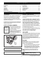
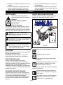
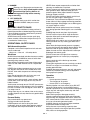
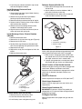
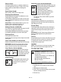
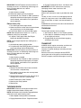
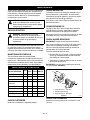
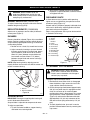
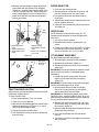
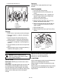
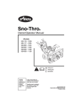
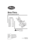
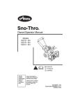
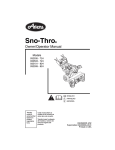
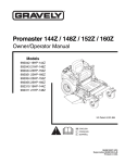
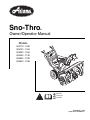
Sno-Thro
®
Owner/Operator Manual
Models
924119 - 1028
924120 - 1024
924333 - 1024
924334 - 1128
924502 - 1332
924503 - 1336
ENGLISH
FRANÇAIS
ESPAÑOL
02488001B 8/00
Supercedes 02488001,A
MODEL CERTIFICATE OF CONFORMITY ISSUED BY THE MANUFACTURER
Ariens Company
655 West Ryan Street
P.O. Box 157
Brillion, Wisconsin 54110-0157
USA
Telephone (920) 756-2141
Facsimile (920) 756-2407
CERTIFICAT DE CONFORMITÉ DU MODÈLE DÉLIVRÉ PAR LE FABRICANT
MODELL-KONFORMITÄTSBESCHEINIGUNG AUSGESTELLT DURCH DEN HERSTELLER
MODELCERTIFICAAT VAN OVEREENSTEMMING AFGEGEVEN DOOR DE FABRIKANT
CERTIFICATO DI COMFORMITÀ DEL MODELLO RILASCIATO DAL PRODUTTORE
CERTIFICADO DE CONFORMIDAD DEL MODELO PROVISTO POR EL FABRICANTE
MODEL KONFORMITETSERKLÆRING UDSTEDT AF FABRIKANTEN
MODELLSERTIFIKAT FOR OVERENSSTEMMELSE UTSTEDT AV FABRIKANT
TILLVERKARENS MODELLCERTIFIKAT OM ÖVERENSSTÄMMELSE
VALMISTAJAN ANTAMA VAKUUTUS MALLIN MÄÄRÄYSTEN MUKAISUUDESTA
We the undersigned, - Je soussigné, - Mit meiner Unterschrift - Wij de ondergetekenden, - Il sottoscritto, - El abajo firmante - Undertegnede, Undertecknaren av detta dokument, - Me, allekirjoittaneet,
ARIENS COMPANY, certify that the Sno Thrower - certifie que le chasse-neige - bestätigen daß die Schneefräse, verklaren dat de sneeuwschüiver certifica che lo spazzavere - certifica que el quita nieves - attesterer at sneslynger - bevitner at snøfreseren - försäkrar att snöslungan, vakuutamme,
että lumilinko:
Category: WALK BEHIND SNO THRO
Make and Trade Name: ARIENS
Model: 924333
Serial # Range: 000101 and up
924334
000101 and up
924502
000101 and up
924503
000101 and up
conform to the specifications of directive 98/37/EC and EC directive (EMC) 89/336/EEC as amended by EC directive 92/31/EEC.
est conforme aux spécifications de la directive 98/37/EC et de la directive EC (EMC) 89/336/EEC modifiée par la directive EC 92/31/EEC.
den Spezifikationen der Direktive 98/37/EC, sowie der EU-Direktive (EMC) 89/336/EEC, modifiziert durch die EU-Directive 92/31/EEC, entspricht.
in overeenstemming zijn met de specificaties in richtlijn 98/37/EG, en EG richtlijn (EMC) 89/336/EEG zoals gerectificeerd in EG richtlijn 92/31/EEG.
sono conformi alla direttiva CE 98/37 e la direttiva CE (EMC) CEE 89/336, emendata dalla direttiva CEE 92/31.
cumple con las especificaciones de la directiva 98/37/EC, 93/44/CEE y 93/68/CEE, y la directiva EC (EMC) 89/336/EEC reformada por la directiva
EC 92/31/EEC.
opfylder specifikationerne i direktiv 98/37/EC og direktiv 89/336/EEC (EMC) med ændringer i EC direktiv 92/31/EEC.
oppfyller spesifikasjonene i direktiv 98/37/EC og EC direktiv (EMC) 89/336/EEC med endringer i EC direktiv 92/31/EEC.
är i överensstämmelse med specifikationerna i direktiv 98/37/EC, och EC direktiv (EMC) 89/336/EEC med ändringar i EC direktiv 92/31/EEC.
On valmistettu 98/37/EC, mukään. Ja neuvostori määräysten, 84/538/EEC tarkennettu 87/252/EEC, 83/180/EEC ja 88/181/EEC mukaan, ja EC
määräysten (EMC) 89/336/EEC tarkennettu määräysten EC 92/31/EEC mukaan.
MAY, 2000
Date/Datum/Data/
Fecha/Dato/Päiväys
Manufacturers of
Outdoor Power Equipment
Manager of Product Conformance
Position/Qualité/Functie/Qualifica/
Puesto/Stilling/Titel/Arvo
2
Signature/Unterschrift/Handtekening/Firma/
Underskrift/Underskrift Handlekening/
Underskrift/Allekirjoitus
Printed in U.S. A. 8-00
CONTROLS AND FEATURES
18
12
11
27
17
14
4
5
3
19
1
6
28
8
29
2
20
15
26
21
13
23 24
30
25
22
16
7
9
10
OS1132
OS0592
Figure 1
ENGLISH
1. Traction Drive Clutch
Lever
2. Attachment Clutch Lever
3. Ignition Key (119, 120)
4. Primer Bulb
5. Choke
6. Throttle
7. Speed Selector
8. Recoil Starter Handle
9. Deflector Remote Control
(119, 502, 503)
10. Chute Crank
(119, 120, 333, 334)
11. Discharge Chute
Deflector
12. Discharge Chute
13. Auger
14. Impeller
15. Scraper Blade
16. Runner
17. Headlight
FRANÇAIS
1. Levier d’embrayage
de la traction
2. Levier d’embrayage de
l’outil
3. Clé de contact (119, 120)
4. Poire d’amorçage
5. Starter
6. Commande des gaz
7. Sélecteur de vitesse
8. Poignée du démarreur
à cordon
9. Commande à distance
du déflecteur
(119, 502, 503)
10. Manivelle de la goulotte
(119,120, 333, 334)
11. Déflecteur de la goulotte
d’évacuation
12. Goulotte d’évacuation
13. Rotor
14. Turbine
15. Lame racleuse
16. Patin
17. Phare
18. Muffler Guard
19. Differential Lock
(120, 333, 334, 502, 503)
20. Axle Lock Pin (119)
21. Battery Cover and
Battery
(333, 334, 502, 503)
22. Heated Handles
23. Heated Handles Switch
24. Chute Rotation Switch
(502, 503)
25. Ignition Key
(333, 334, 502, 503)
26. Solenoid Compartment
(333, 334, 502, 503)
27. Electric Chute Motor
(502, 503)
28. Wing Knobs
29. Electric Starter
(119, 120)
30. Auger Gearcase
18. Garant du silencieux
19. Blocage du différentiel
(120, 333, 334, 502, 503)
20. Broche de blocage de
l’essieu (119)
21. Couvercle de batterie
et batterie
(333, 334, 502, 503)
22. Poignées chauffées
23. Commande de poignées
chauffées
24. Commande de rotation
de la goulotte (502, 503)
25. Clé de contact
(333, 334, 502, 503)
26. Compartiment du
solénoïde
(333, 334, 502, 503)
27. Moteur électrique de la
goulotte (502, 503)
28. Boutons
29. Démarreur électrique
(119, 120)
30. Boîtier de renvoi du rotor
WARNING
The engine exhaust from this product
contains chemicals known to the State
of California to cause cancer, birth
defects or other reproductive harm.
3
ESPAÑOL
1. Palanca del embrague de la transmisión de la tracción
2. Palanca del embrague del accesorio
3. Llave de encendido (119, 120)
4. Botón del cebador
5. Estrangulador
6. Aceleración
7. Selector de velocidad
8. Manilla de retroceso del motor de arranque
9. Control remoto del deflector (119, 502, 503)
10. Manivela de la tolva (119, 120, 333, 334)
11. Deflector de la tolva de descarga
12. Tolva de descarga
13. Sinfín
14. Propulsor
15. Cuchilla raspadora
16. Guía
17. Luces delanteras
18. Protector del silenciador
19. Traba del diferencial (120, 333, 334, 502, 503)
20. Pasador de traba del eje (119)
21. Cubierta de la batería y batería (333, 334, 502, 503)
22. Manillas térmicas
23. Interruptor de las manillas térmicas
24. Interruptor de rotación de la tolva (502, 503)
25. Llave de encendido (333, 334, 502, 503)
26. Compartimento del solenoide (333, 334, 502, 503)
27. Motor de la tolva eléctrica (502, 503)
28. Perillas de mariposa
29. Arranque eléctrico (119, 120)
30. Caja de engranajes del sinfín
4
TABLE OF CONTENTS
Controls and Features . . . . . . . . . . . . . . . . . . . . . . 3
Storage . . . . . . . . . . . . . . . . . . . . . . . . . . . . . . . . . 20
Introduction . . . . . . . . . . . . . . . . . . . . . . . . . . . . . . 5
Accessories . . . . . . . . . . . . . . . . . . . . . . . . . . . . . 21
Safety . . . . . . . . . . . . . . . . . . . . . . . . . . . . . . . . . . . 6
Service Parts . . . . . . . . . . . . . . . . . . . . . . . . . . . . 21
Assembly . . . . . . . . . . . . . . . . . . . . . . . . . . . . . . . . 9
Troubleshooting . . . . . . . . . . . . . . . . . . . . . . . . . . 21
Operation . . . . . . . . . . . . . . . . . . . . . . . . . . . . . . . 11
Specifications. . . . . . . . . . . . . . . . . . . . . . . . . . . . 22
Maintenance . . . . . . . . . . . . . . . . . . . . . . . . . . . . . 15
Warranty . . . . . . . . . . . . . . . . . . . . . . . . . . . . . . . . 23
Service and Adjustments . . . . . . . . . . . . . . . . . . 17
INTRODUCTION
THE MANUAL
PRODUCT REGISTRATION
Before operation of unit, carefully and completely read
your manuals. If used improperly, this unit could be
dangerous and cause personal injury or property
damage. The contents will provide you with safety
instructions for the safe use of your unit during normal
operation and maintenance.
A warranty registration card must be filled out, signed,
and returned at time of purchase. This card activates
the warranty.
All reference to left, right, front, or rear are given from
operator standing in operation position and facing the
direction of forward travel.
MODEL AND SERIAL NUMBERS
Transfer
model & serial
number label
from product
registration
here.
When ordering replacement parts
or making service inquiries, know
the Model and Serial numbers of
your unit and engine.
Numbers are located on the product
registration form in the unit literature
package. They are printed on a
serial number label, located on the
frame of your unit.
UNAUTHORIZED REPLACEMENT PARTS
Use only Ariens replacement parts. The replacement of
any part on this vehicle with anything other than an
Ariens authorized replacement part may adversely
affect the performance, durability, or safety of this unit
and may void the warranty. Ariens disclaims liability for
any claims or damages, whether warranty, property
damage, personal injury or death arising out of the use
of unauthorized replacement parts.
For a brief list of replacement parts see Service Parts
in this manual. To obtain a complete parts manual, find
your model and serial number. Then go to
www.ariens.com or call 1-800-678-5443.
DISCLAIMER
Ariens reserves the right to discontinue, make changes
to, and add improvements upon its products at any time
without public notice or obligation. The descriptions
and specifications contained in this manual were in
effect at printing. Equipment described within this
manual may be optional. Some illustrations may not be
applicable to your unit.
DELIVERY
Serial
Number
Label
Figure 2
OS1890
•
Record Unit Model and Serial numbers here.
•
Record Engine Model and Serial number here.
Customer Note: If you have purchased this product
without complete assembly and instruction by your
retailer, it is your responsibility to:
1. Read and understand all assembly instructions in
this manual. If you do not understand or have
difficulty following the instructions, contact your
nearest Ariens Dealer for assistance. Make sure
all assembly has been properly completed.
NOTE: To locate your nearest Ariens Dealer, call
1-800-678-5443 or go to www.ariens.com on the
internet.
WARNING: Improper assembly or
adjustments can cause serious injury.
GB - 5
© Copyright 2000 Ariens Company
2. Understand all Safety Precautions provided in the
manuals.
3. Review control functions and operation of the
unit. Do not operate the Sno-Thro unless all
controls function as described in this manual.
4. Review recommended lubrication, maintenance
and adjustments.
5. Review Limited Warranty Policy. Fill out Original
Purchaser Registration Card and return the card
to Ariens Company.
SAFETY
SAFETY ALERTS
SAFETY DECALS AND LOCATIONS
Look for these symbols to point out
important safety precautions. They mean:
ALWAYS replace missing or damaged Safety Decals.
Refer to figure below for Safety Decal locations.
Attention!
1
Personal Safety Is Involved!
Become Alert!
Obey The Message!
08085000
The safety alert symbol is used in decals on the unit
and with proper operation procedures in this manual.
Understand the safety message. It contains important
information about personal safety on or near the unit.
3
2
DANGER: IMMINENTLY HAZARDOUS
SITUATION! If not avoided, WILL RESULT in
death or serious injury.
WARNING: POTENTIALLY HAZARDOUS
SITUATION! If not avoided, COULD RESULT
in death or serious injury.
4
CAUTION: POTENTIALLY HAZARDOUS
SITUATION! If not avoided, MAY RESULT in
minor or moderate injury. It may also be used
to alert against unsafe practices.
Figure 3
OS0573
1 & 2. DANGER!
Keep clear of auger while engine is running
NOTATIONS
NOTE: General reference information for proper operation and maintenance practices.
IMPORTANT: Specific procedures or information
required to prevent damage to unit or attachment.
Read Owner/Operator Manual.
•
PRACTICES AND LAWS
Practice usual and customary safe working
precautions, for the benefit of yourself and others.
Understand and follow all safety messages. Be alert to
unsafe conditions and the possibility of minor,
moderate, or serious injury or death. Learn applicable
rules and laws in your area. Always follow the practices
set forth in this manual.
Allow operation only by properly trained adult,
never children.
Stop engine and remove ignition key prior to
leaving operator’s position for any reason.
Read manual prior to servicing.
• Keep all controls, guards and safety devices properly
serviced and functional.
REQUIRED OPERATOR TRAINING
Original purchaser of this unit was instructed by the
seller on safe and proper operation by the seller. If unit
is to be used by someone other than original
purchaser; loaned, rented or sold, ALWAYS provide
this manual and any needed safety training before
operation.
GB - 6
Never direct discharge towards persons or
property that may be injured or damaged by
thrown objects.
Keep people away from unit while operating.
Keep children out of work area and under
watchful care of a responsible adult.
3. DANGER!
Rotating parts! Stop engine and remove key
before clearing. High speed impeller rotates
below discharge opening. Wait for all
moving parts to stop before removing
clogs or servicing.
4. HOT SURFACES!
DO NOT touch parts which are hot from
operation. ALWAYS allow parts to cool.
ASSEMBLY SAFETY RULES
Read, understand, and follow all safety practices in
Owner/Operator Manual before beginning assembly.
Failure to follow instructions could result in personal
injury and/or damage to unit.
ALWAYS remove key and/or wire from spark plug
before assembly. Unintentional engine start up can
cause death or serious injury.
OPERATIONAL SAFETY RULES
Walk Around Inspection
Complete a walk around inspection of unit and work
area to understand:
• Work area • Your unit • All safety decals
Work Area
ALWAYS check overhead and side clearances carefully
before operation. ALWAYS be aware of traffic when
operating along streets or curbs.
Keep children and people away. Keep children out of
work area and under watchful care of a responsible
adult.
NEVER allow children to operate or play on or near
unit. Be alert and shut off unit if children enter area.
DO NOT allow adults to operate unit without proper
training.
Keep area of operation clear of all toys, pets, and
debris. Thrown objects can cause injury.
Check for weak spots on dock, ramps or floors. Avoid
uneven work areas and rough terrain. Stay alert for
hidden hazards.
Avoid uneven and rough terrain. DO NOT operate near
drop offs, ditches, or embankments. Unit can suddenly
turn over if a wheel is over the edge of a cliff or ditch, or
if an edge caves in.
Falling snow, fog, etc. can reduce vision and cause an
accident. Operate unit only when there is good visibility
and light.
Personal Safety
Only trained adults may operate unit.
Training includes actual operation.
NEVER operate unit after or during the use of
medication, drugs or alcohol. Safe operation requires
your complete and unimpaired attention at all times.
NEVER allow anyone to operate this unit when their
alertness or coordination is impaired.
DO NOT operate unit without wearing adequate winter
outer garments. Wear adequate safety gear and
protective gloves. Wear proper footwear to improve
footing on slippery surfaces.
DO NOT wear loose clothing or jewelry and tie back
hair that may get caught in rotating parts.
Protect eyes, face and head from objects that may be
thrown from unit. Wear appropriate hearing protection.
Avoid sharp edges. Sharp edges can cut. Moving parts
can cut off fingers or a hand.
ALWAYS keep hands and feet away from all rotating
parts during operation. Rotating parts can cut off body
parts.
ALWAYS keep hands away from all pinch points.
DO NOT touch unit parts which might be hot from
operation. Allow parts to cool before attempting to
maintain, adjust or service.
NEVER place your hands or any part of your body or
clothing inside or near any moving part while unit is
running.
Never direct discharge towards persons or property
that may be injured or damaged by thrown objects. Use
extreme caution on gravel surfaces. Stay alert for
hidden hazards or traffic. Adjust Runners so Scraper
Blade does not contact gravel.
DO NOT throw snow any higher than necessary.
Deflected materials can cause injury and property
damage.
Always stand clear of the discharge area when
operating this unit.
Fumes from engine exhaust can cause injury or death.
DO NOT run engine in an enclosed area. Always
provide good ventilation.
ALWAYS disengage attachment, stop unit and engine,
remove key and allow moving parts to stop before
leaving operator’s position.
Operation
Understand:
• How to operate all controls
• The functions of all controls
• How to STOP in an Emergency
Rotating impeller can cause serious injury. DO NOT
unclog unit while engine is running. When leaving
operator’s position for any reason, ALWAYS disengage
auger, stop unit and engine, remove key and allow
moving parts to stop.
Before starting engine, disengage control(s).
Use only approved extension cords and receptacles
when starting units equipped with Electric starter. DO
NOT connect electric starter cord to any wiring system
that is not a three wire grounded system.
ALWAYS allow unit and engine to adjust to outdoor
temperatures before clearing snow.
Always be sure of your footing, especially when
operating in reverse or leaving the operator’s position.
Walk, never run during operation.
GB - 7
DO NOT operate at too fast a rate.
Slow down and turn corners slowly.
Do not operate in reverse unless absolutely necessary.
ALWAYS back up slowly. Always look down and behind
before and while backing.
Disengage attachment drive when traveling from one
work area to another.
Abnormal Vibrations are a warning of trouble. Striking a
foreign object can damage unit. Immediately stop unit
and engine. Remove key and wait for all moving parts
to stop. Remove wire from spark plug. Inspect unit and
make any necessary repairs before restart.
Before cleaning, removing clogs or making any
inspections, repairs, etc.: disengage clutch(es),
stop unit and engine, remove key, allow moving
parts to stop. Allow hot parts to cool.
Run unit a few minutes after clearing snow to prevent
freeze-up of attachment.
Disengage attachment when not in use. Before starting
engine: disengage all clutches and shift into neutral.
Adjust runners to clear gravel or crushed rock surfaces
safely.
Never leave a running unit unattended. ALWAYS shut
off engine before leaving unit. ALWAYS remove key to
prevent unauthorized use.
Never carry passengers.
Check clutch and brake operation frequently. Adjust
and service as required. All motion of drive wheels and
auger/impeller must stop quickly when control levers
are released.
Hazardous Slopes
DO NOT operate on steep slopes. DO NOT clear snow
across the face of slopes. Keep all movement on
slopes slow and gradual. DO NOT make sudden
changes in speed or direction. Use a slow speed to
avoid stops or shifts on slopes. Avoid starting or
stopping on a slope.
DO NOT park unit on a slope unless absolutely
necessary. When parking on a slope always block the
wheels.
Transport
Use extra care when loading or unloading unit onto
trailer or truck.
Secure unit chassis to transport vehicle. NEVER
secure from rods or linkages that could be damaged.
DO NOT transport machine while engine is running.
FUEL SAFETY RULES
Fuel is highly flammable and its vapors are explosive.
Handle with care. Use an approved fuel container.
NO smoking, NO sparks, NO flames. ALWAYS allow
engine to cool before servicing.
NEVER fill fuel tank when engine is running or hot from
operation.
NEVER fill or drain fuel tank indoors.
Replace fuel cap securely and clean up spilled fuel.
BATTERY
Avoid Electric Shock. Objects contacting both battery
terminals at the same time may result in injury and unit
damage. DO NOT reverse battery connections.
Explosive Gases from battery can cause death or
serious injury. Poisonous battery fluid contains sulfuric
acid and its contact with skin, eyes or clothing can
cause severe chemical burns.
No flames, No sparks, No smoking near battery.
ALWAYS wear safety glasses and protective gear near
battery.
DO NOT TIP battery beyond a 45˚ angle in any
direction.
ALWAYS keep batteries out of reach of children.
Battery posts, terminals and related accessories
contain lead and lead compounds, chemicals known to
the State of California to cause cancer and
reproductive harm. Wash hands after handling.
Battery Electrolyte First Aid
Follow First Aid directions for contact with battery fluid.
• External Contact: Flush with water.
• Eyes: Flush with water for at least 15 minutes and
get medical attention immediately!
• Internal Contact: Drink large quantities of water.
Follow with Milk of Magnesia, beaten egg or
vegetable oil. Get medical attention immediately!
In case of internal contact, DO NOT induce vomiting!
MAINTENANCE AND SERVICE SAFETY
RULES
Cleaning
Keep unit free of ice or other debris. Clean up oil or fuel
spills.
Spark Arrester
This product is equipped with an internal combustion
type engine. DO NOT use unit on or near any
unimproved, forest-covered or brush covered land
unless exhaust system is equipped with a spark
arrester meeting applicable local, state or federal laws.
A spark arrester, if it is used, must be maintained in
effective working order by operator.
Before tipping unit up onto housing, remove fuel so no
spills will occur and remove battery (if equipped).
Ensure unit is secure and will not tip over during
maintenance.
ALWAYS keep protective structures, guards, and
panels in good repair, in place and securely fastened.
NEVER modify or remove safety devices.
DO NOT change engine governor settings or
over-speed engine.
Before cleaning, removing clogs or making any
inspections, repairs, etc.: disengage clutch(es),
stop unit and engine, remove key, allow moving
parts to stop. Allow hot parts to cool.
GB - 8
Fumes from engine exhaust can cause injury or death.
DO NOT run engine in an enclosed area. Always
provide good ventilation.
ALWAYS maintain unit in safe operating condition.
Damaged or worn out muffler can cause fire or
explosion.
Keep all hardware properly tightened. Check shear
bolts frequently.
STORAGE SAFETY RULES
NEVER store unit with fuel in fuel tank, inside a
building where any ignition sources are present.
Allow engine to cool completely before storing in
closed area or covering unit.
For extended storage, clean unit thoroughly. See
Engine Manual for proper storage.
ACCESSORY AND ATTACHMENT SAFETY
RULES
Use only attachments or accessories designed for your
unit.
Check attachment components frequently. If worn or
damaged, replace with manufacturer’s recommended
parts.
ASSEMBLY
ASSEMBLY
WARNING: AVOID INJURY. Read and
understand Assembly, Fuel and Battery
Safety Rules before proceeding.
11
Tools Required:
• Pliers
• Open-End Wrenches: 3/8, 7/16, 1/2, 9/16 and/or
Adjustable Wrench
• Tire Gauge
2
4
10
3
UNPACKING UNIT
9
1
8
7
WARNING: Dropping or tipping over boxed
unit could result in personal injury or damage
to unit.
6
5
PACKAGE CONTENTS
Chute Crank
(119,120,333,334)
1. Chute Crank Handle
2. Speed Selector
Lever
3. Wing Knobs
4. Chute Deflector
Remote
5. Attachment Clutch
Arm
6. Clutch Cable Spring
Discharge
Chute
7. Clutch Cable
8. Shift Rod
9. Traction Clutch
Cable
10. Wiring Harness
(333,334,502,503)
11. Key Switch
(333,334,502,503)
Figure 5
DS0162
Handlebar and Shift Rod
1. Remove lower wing knobs on handlebar
assembly (Figure 5).
2. Remove upper wing nut and bolt on shift rod.
3. Loosen upper wing knobs on handlebar.
4. Loosen lower wing nut and bolt on shift rod.
5. Make sure speed selector lever is in 2nd or 3rd
position.
6. Rotate handlebar up so wing knob holes align.
Install and tighten all wing knobs.
Lit
er
Paatur
ck e
Sno-Thro
Unit
Figure 4
GB - 9
Deflector Remote (502,503,119)
7. Install wing nut and bolt removed in step 2 onto
shift rod and tighten hardware.
1. Slide cable end through hole on bracket on left
side of chute.
2. Attach cable eye to stud on deflector. Hold in
place with flat washer and e-ring.
3. Check deflector travel. Adjust nut on cable end
under handlebar to obtain full travel.
Install Discharge Chute and Crank
(119,120,333,334)
1. Grease discharge chute ring on blower housing
(if not already greased).
2. Slide chute ring under front clip on blower
housing and put chute on housing.
3. Remove mounting hardware from top of engine.
4. Secure chute by fastening chute strap to engine
with hardware just removed.
5. Slide chute crank rod through bracket under
handlebar and through hole in panel.
6. Align chute crank rod with the universal joint on
chute and fasten with spring clip.
1
2
3
Install Discharge Chute - Electric Rotation
(502,503)
1.
2.
3.
4.
Remove chute motor cover.
Remove the six (6) nuts from ring gear (Figure 6).
Remove two (2) half rings.
Position Discharge Chute over threaded studs
with the chute opening facing the electric motor.
5. Replace the half rings.
6. Replace the six (6) nuts and tighten to 120 in. lbs.
torque.
7. Replace chute motor cover.
3
1
2
1. Cable Eye
2. Flat Washer and E-Ring
3. Deflector Cable
Figure 7
OS1981
Check Attachment Clutch
Clutch cable spring should expand approximately 3/8”
(9mm) beyond free state when clutch is engaged.
1. When clutch is disengaged, lower end of clutch
arm should return to its maximum down position,
with slight amount of slack in control cable.
2. If proper spring extension is not obtained, adjust
Attachment Idler per Service and Adjustments.
Check Function of Dual Handle Interlock
Without the engine running, press down (engage) both
clutch levers. Release attachment clutch lever.
Attachment clutch should remain engaged until traction
clutch lever is released, then both clutches must
disengage.
Check Tire Pressure
Check tire pressure and adjust to 14 PSI (96.5 kNm2).
Check Auger Gearcase Oil
Check oil level in auger gearcase (see Service and
Adjustments).
1. Ring Gear Nuts
2. Half Rings
3. Discharge Chute
Figure 6
Connect Battery (333,334,502,503)
1. Remove wing nuts from battery cover.
2. Install wire lead to battery terminal.
3. Install battery cover and tighten wing nuts.
Check Engine Crankcase Oil
OS1930
IMPORTANT: Engines on all Sno-Thro models are
shipped with oil in crankcase. Refer to Engine Manual
for detailed instructions.
Fill Engine Fuel Tank
Refer to Engine Manual for proper fuel type and tank
capacity.
GB - 10
Check Function of all Controls
Ensure unit runs and performs properly. Refer to
Operation.
OPERATION
Ignition Key (12V start on dash panel)
WARNING: AVOID INJURY. Read and
understand Operational, Fuel and Battery
Safety Rules before proceeding.
1
2
3
STANDARD CONTROLS
OS0232
See Figure on page 3 for all Controls and Features
locations.
Primer Bulb
Pushing the Primer Bulb in adds fuel for
easier engine start (see Starting and Shut
Off).
Dual Handle Interlock
When Attachment Clutch and then Traction Drive
Clutch are engaged, the Attachment Clutch will remain
engaged (lever down) if released. To stop attachment,
release Traction Drive Clutch and both clutches will
disengage.
Traction Drive Clutch - Left Hand Lever
2
1
OL2701
Squeeze the Traction Drive Clutch
Lever against the Handlebar (1) to
engage wheel drive for propelling
unit. Forward speed will vary
according to snow depth and
moisture content.
Release lever to stop movement (2).
NOTE: When traveling to or from the area to be
cleared, press down on the handlebars enough to raise
the front of the unit slightly off the surface. Engage the
traction drive clutch without engaging the auger drive
clutch.
OS1321
Speed Selector
The Speed Selector controls the unit travel in a forward
or reverse direction when positioned in notch of speed.
Forward:
6
(6) “Fastest”
5
(1) “Slow” (Best used for removing deep
4
or
hard packed snow)
3
Reverse:
2
1
(1) “Slow”
(2) “Fast”
1
2
OS1190
Attachment Clutch - Right Hand Lever
Squeeze Attachment Clutch Lever
against Handlebar (1) to engage
attachment. Release both clutch
levers (2) to disengage power and
apply brake to attachment.
1
IMPORTANT: If the belt squeals
when the attachment clutch lever is
OL2691
engaged, the attachment drive may
be frozen. Immediately release the
attachment clutch lever and move the unit into a heated
area to thaw.
2
2
1
OS1431
IMPORTANT: DO NOT change motion
from forward to reverse with clutch
engaged. Forward speed can be
changed without declutching.
Choke Control Knob
1. Choke Closed position: chokes off
air to engine for easier start.
1 2. Choke Open position: allows for
normal operation.
IMPORTANT: Gradually open choke
after engine starts.
2
OS1300
Throttle
1
Ignition Key (120V start on engine)
Key Switch has two positions:
1. “Stop”
2. “Run”
NOTE: DO NOT twist key after it is
inserted.
The ignition switch is operated by a
removable key. It has three positions:
1.“Stop”
2.“Run”
3.“Start”
2
3
STOP
4
OL2720
GB - 11
The Throttle controls the engine speed. To
increase or decrease the engine speed,
adjust to:
1.“Fast” (normal or warm starts)
2.“Part-Throttle”
3.“Slow” (cold weather starts)
4.“Stop” (engine is off)
Electric Starter
Differential Lock (120,333,334,502,503)
The Electric Starter will start a properly choked and
cranked engine when the key is turned (12V) or start
button (120V) is pushed. Refer to Starting and
Shut-Off.
Differential Lock knob is located on the Left
Wheel Hub. With differential locked power is
applied equally to both wheels.
To engage differential lock:
2
• Pull and turn knob to LOCKED (1)
position and release (knob will snap in
OL2730
place when positioned correctly).
To resume differential action for transport:
• Pull and turn knob to UNLOCKED (2) position
and release.
1
Recoil Starter Handle
When pulled, handle will turn engine over.
Discharge Chute Deflector
ALWAYS position Discharge Chute Deflector at safe
angle before starting engine.
Push Deflector handle forward or down to throw snow
lower. Pull Deflector Handle up or to the rear to throw
snow higher.
IMPORTANT: If Chute Deflector does not stay in set
position, adjust as directed in Service and
Adjustments, or repair before operation.
Axle Lock Pin (119)
The axle lock pin is located on the right wheel hub.
Moving pin from the hub to the axle shaft allows the
right wheel to turn freely.
Scraper Blade
Deflector Remote (119,502,503)
Place Deflector into position before operation. DO NOT
throw snow any higher than necessary.
Push Deflector Remote forward to throw snow lower.
Pull Deflector Remote back to throw snow higher.
Discharge Chute
Discharge Chute rotates 220°.
ALWAYS position discharge chute straight ahead while
starting unit.
Chute Crank Handle (119,120,330,334)
Rotate the Chute with Discharge Chute Crank Handle.
IMPORTANT: DO NOT force frozen Chute controls.
Start engine and run for 3-5 minutes to thaw. If still
frozen, take to warm place until controls are free.
Chute Rotation Switch (502,503)
2
1
OS1970
Press the chute rotation
switch right (1) to rotate
chute clockwise. Press the
chute rotation switch left
(2) to rotate chute
counterclockwise.
The scraper blade allows the back of the housing to
keep better contact with the surface being cleared. It
also prevents damage to the housing from normal
wear.
IMPORTANT: DO NOT allow Scraper Blade to wear
too far or Auger/Impeller housing will become
damaged.
Runners
For operation on gravel surface, lower Runners so that
housing will not pick up gravel. On concrete, blacktop
or packed snow surfaces raise Runners so that
Scraper Blade scrapes clean.
Headlight
NOTE: Lamp remains on at all times for longer lamp
life. Lamp is more sensitive to fatigue when unlit.
FILLING FUEL TANK
WARNING: FLAMMABLE FUEL and its
EXPLOSIVE VAPORS can result in death or
serious injury.
Handle fuel with extreme care. ALWAYS use
an approved fuel container.
No Smoking! No Lighted Materials!
No Open Flames!
Allow engine to cool before any service.
Heated Handles
1
2
OS1950
Turn the heated handles switch to the
ON (1) position to activate. Turn the
switch to the OFF (2) position to
deactivate.
To add fuel to Fuel Tank:
1. ALWAYS place unit in open or well ventilated
area.
2. Stop engine and allow to cool.
3. Clean Fuel Cap and surrounding area to prevent
dirt from entering Fuel Tank.
4. Remove Cap.
GB - 12
IMPORTANT: DO NOT use gasohol or gasoline
containing alcohol. See Engine Manual for correct type
and grade of fuel.
5. Fill fuel tank to within 1/2" (1,2 cm) below bottom
of filler neck with unleaded gasoline. Tank
capacity is 1 gallon (3,8 liters).
6. Replace Fuel Cap and tighten.
7. ALWAYS clean up any spilled fuel.
PRE-START
Frozen Impeller
IMPORTANT: Before engine start check Impeller to be
sure it is not frozen. With key in “Stop” position,
squeeze Attachment Clutch Lever to Engaged position
and pull Recoil Starter Handle. If Impeller is frozen,
(cannot pull Starter Handle) move unit to a heated area
and thaw to prevent possible damage.
Differential Lock (120,333,334,502,503)
ALWAYS engage differential lock (located in left wheel
hub) for best traction when throwing snow.
Axle Lock (119)
Keep locking pin on the right wheel hub for best traction
when throwing snow.
Function of Clutches
IMPORTANT: Check Clutch/Brake function before
each use. If the Impeller does not stop quickly when
the Attachment Clutch Lever is released or there is no
noticeable increase in the Lever force before contacting
the Handlebar, adjust as directed in Service and
Adjustments Section, or repair before operation.
Dual Handle Interlock
Check by pressing down on Clutch Levers (engaging
both clutches). Release Attachment Clutch Lever;
attachment clutch should remain engaged until Traction
Clutch Lever is released, then both clutches must
disengage.
Crankcase Oil
Check and add crankcase oil if required. Refer to
Engine Manual.
Fuel Tank
Check and add fuel to fuel tank if required. Refer to
Filling Fuel Tank on page 12.
Runners
Check and adjust Runners (see Service and
Adjustments). Allow 1/8" (3mm) between scraper blade
and hard, smooth surface(s). Allow 1-1/4" (30mm)
between scraper blade and uneven surface(s).
STARTING AND SHUT OFF
Emergency Shut Off
Immediately release both control levers to stop unit in
an emergency. Stop engine, remove Key and wait for
all rotating parts to stop before leaving operator’s
position.
Manual Start
1. Turn discharge chute straight ahead.
2. Make sure that the traction clutch and attachment
drive clutch levers are fully disengaged.
3. Push Primer Bulb 2 or 3 times for cold engine.
NOTE: When temperature is below -15˚ F (-26˚ C)
additional priming may be needed.
4. If engine is cold, apply choke. A warm engine
requires less choking than a cold engine. See
Engine Manual for detailed instructions.
5. Set throttle to proper starting position.
6. Insert key into Ignition Switch.
7. Turn key into RUN position (12V). Push key on
engine into RUN position (120V).
8. Grasp starter handle and pull rope out slowly until
it pulls harder. Let rope rewind slowly.
9. Pull rope with a rapid continuous full arm stroke.
Let rope rewind slowly.
IMPORTANT: DO NOT let Starter Handle snap against
Starter.
10. Repeat until engine starts. (If engine does not
start, refer to Troubleshooting.)
11. Adjust choke as needed.
12. Set throttle to “Part Throttle” or “Slow” position for
adaptation to Ambient temperature or travel. Set
throttle to “Fast” position for normal operation.
Electric Start (120V)
1. Connect extension cord to prongs on starter. Plug
cord into 120V 3-wire, grounded outlet.
2. Turn discharge chute straight ahead.
3. Make sure that the traction clutch and attachment
drive clutch levers are fully disengaged.
4. Push Primer Bulb 2 or 3 times for cold engine.
NOTE: When temperature is below -15˚ F (-26˚ C)
additional priming may be needed.
5. Insert key into ignition switch on engine and push
into "Run" position. DO NOT twist key after it is
inserted.
6. If engine is cold, apply choke. A warm engine
requires less choking than a cold engine. See
Engine Manual for detailed instructions.
7. Set throttle to proper starting position.
8. Press starter button on engine until engine starts.
GB - 13
IMPORTANT: DO NOT operate starter more than 15
seconds per minute, as overheating and damage can
occur. (If engine does not start, refer to
Troubleshooting.)
9. Adjust choke as needed.
10. Disconnect power cord from receptacle.
11. Set throttle to “Part Throttle” or “Slow” position for
adaptation to Ambient temperature or transport.
Once achieved, set throttle to “Fast” position for
normal operation.
Electric Start (12V)
1. Turn discharge chute straight ahead.
2. Make sure that the traction clutch and attachment
drive clutch levers are fully disengaged.
3. Push Primer Bulb 2 or 3 times for cold engine.
NOTE: When temperature is below -15˚ F (-26˚ C)
additional priming may be needed.
4. If engine is cold, apply choke. See Engine
Manual for detailed instructions.
NOTE: A warm engine requires less choking than a
cold engine.
5. Set throttle to proper starting position.
6. Put ignition key into START position until engine
starts and release into the RUN position.
IMPORTANT: DO NOT operate starter more than 15
seconds per minute, as overheating and damage can
occur. (If engine does not start, refer to
Troubleshooting.)
7. Adjust choke as needed.
8. Set throttle to “Part Throttle” or “Slow” position for
adaptation to Ambient temperature or transport.
Once achieved, set throttle to “Fast” position for
normal operation.
3. Engage Traction Drive Clutch - Left Hand Lever.
IMPORTANT: DO NOT overload unit capacity by
attempting to clear snow at too fast a rate.
Tips for Operation
Snow is best removed as soon as possible after snow
fall.
To clear an area, run unit in an overlapping series of
paths. For large areas; start in the middle and throw
snow to each side, so snow is not cleared more than
once.
ALWAYS direct snow away from area to be cleared and
with direction of the wind.
TRAVELING
To travel from one work area to another:
1. Set Throttle to "Slow" or "Part-Throttle" position.
2. Press down on handlebars enough to raise front
of unit slightly off surface.
3. Engage wheel drive clutch without engaging
attachment drive clutch.
TRANSPORT
ALWAYS shut off engine, remove key and drain fuel
when transporting unit on a truck or trailer.
Use extra care when loading or unloading unit onto
trailer or truck.
Secure unit chassis to transport vehicle. NEVER
secure from rods or linkages that could be damaged.
DO NOT transport machine while engine is running.
Normal Shut Off
1. Release Traction Drive Clutch Lever and allow
unit to come to a complete stop.
2. Run Impeller a few minutes after use to prevent
freeze-up of Impeller.
3. Release Attachment Clutch Lever and wait for all
moving parts to come to a complete stop.
4. Move Throttle to the “Slow” Position.
5. Move key into “Stop” position.
6. Remove key.
THROWING SNOW
IMPORTANT: Allow unit and engine to adjust to the
outdoor temperatures before clearing snow.
NOTE: Attachment clutch should be engaged before
wheel drive clutch when throwing snow.
1. Select Speed Control position and direction.
2. Engage Attachment Clutch - Right Hand Lever.
GB - 14
MAINTENANCE
Ariens Dealers will provide any service or adjustments
which may be required to keep your unit operating at
peak efficiency. Should engine service be required,
contact an Ariens dealer or an authorized engine
manufacturer's service center.
WARNING: AVOID INJURY. Read and
understand Maintenance and Service and
Battery Safety Rules in Safety section before
attempting any maintenance.
Change oil after first 5 hours of operation, thereafter
change oil every 25 hours (more often if required).
Refer to Engine Manual for detailed instructions.
Run engine just prior to changing oil. Warm oil will flow
more freely and carry away more contamination.
WARNING: Before tipping unit up onto
housing, remove fuel so no spills will occur
and remove battery (if equipped). Ensure unit
is secure and will not tip over during
maintenance.
CHECK AUGER GEARCASE
Place unit in service position when required. Place unit
on a flat level surface. Tip unit forward onto front of
Impeller housing for service. Assure unit is secure and
will not tip over. Strap and clamp onto bench if needed.
MAINTENANCE SCHEDULE
The chart below shows the recommended
maintenance schedule that should be performed on a
regular basis. More frequent service may be required
due to working conditions (heavy loads, high ambient
temperatures, dusty conditions, or airborne debris).
MAINTENANCE SCHEDULE
Check Fasteners
Daily
The engine crankcase oil should be checked every 5
hours of operation. Oil level MUST be maintained in
safe operating range on dipstick at all times or engine
damage will result (See Engine Manual).
Park unit on a level surface. Refer to Engine Manual for
detailed instructions.
CHANGE ENGINE OIL
SERVICE POSITION
Service Performed
CHECK ENGINE OIL
IMPORTANT: Proper oil level must be maintained.
Gear cases are filled to the correct level at the factory.
Unless there is evidence of leakage, no additional
lubricant should be required. Check for evidence of
leakage every 25 hours of operation.
To ensure adequate lubricant level:
1. Remove filler plug (Figure 8). Lubricant must be
at least up to bottom of lubricant filler hole with
unit resting on a level-surface.
2. Add lubricant if required. Allow oil to drain to level
of plug and replace plug.
IMPORTANT: Use only Ariens special gear lubricant
L-2 (Part Number 00008000).
Every Every Every
5 hrs. 25 hrs. 100 hrs.
1
•
Check Engine Oil
•
Change Engine Oil
*
2
•
Check Auger
Gearcase
•
Check Tire Pressure
•
General Lubrication
•
Battery Maintenance
•
Clean Engine
3
2
1. Auger Gearcase - Cast Iron
2. Oil Fill and Drain Plug
3. Auger Gearcase - Aluminum
•
Figure 8
OS0620
* First Maintenance Only
CHECK TIRE PRESSURE
CHECK FASTENERS
Make sure all hardware is tightened properly.
Maintain the unit tire pressure at a maximum 14 PSI
(97 kPa).
GB - 15
GENERAL LUBRICATION
CLEAN BATTERY (Model 333,334,502,503)
Sno-Thro should be lubricated (Figure 9) at beginning
of season or every 25 operating hours.
IMPORTANT: DO NOT allow grease or oil to get on
friction wheel, drive disc or belts.
IMPORTANT: Wipe each fitting clean before and after
lubrication.
NOTE: Apply Stens Mix Hi-Temp Grease or equivalent
to the lubrication fittings. See Service Parts.
Auger Shaft
NOTE: To grease auger shaft, remove shear bolt nuts,
and shear bolts. Turn auger on shaft while applying
grease at zerk fittings. Replace shear bolt per instructions in Service and Adjustments.
2
WARNING: AVOID INJURY. Read and
understand Battery Safety Rules in Safety
section before attempting any maintenance.
IMPORTANT: Battery is maintenance free. Do not
tamper with or attempt to open battery. See Service
and Adjustments for charging procedures.
Terminals
Keep battery and its terminals clean.
IMPORTANT: Remove battery from unit before
cleaning.
Remove corrosion from battery terminals and cable
connections with a wire brush, then wash with a weak
baking soda solution.
After cleaning, apply a thin coat of grease or petroleum
jelly to terminals and cable ends to retard corrosion.
CLEAN ENGINE
1
1
1
Refer to Engine Manual for detailed instructions.
1
8
6
5
4
7
3
1. Auger and Shaft
2. Discharge Chute
3. Sprocket/Pinion
Assembly
4. Axle Shaft
5.
6.
7.
8.
Shift Lever Arm
Pinion Chain
Hex Shaft
Shift Link
Figure 9
GB - 16
SERVICE AND ADJUSTMENTS
2. With runners adjusted to their full up position,
reposition scraper blade down, flush with runners,
and tighten lock nuts.
WARNING: AVOID INJURY. Read and
understand Maintenance and Service and
Battery Safety Rules in Safety section before
attempting any maintenance.
DISCHARGE CHUTE
If Chute does not stay in position while operating,
tighten nut on carriage bolt at pivot point to increase
tension on spring (Figure 11).
Smooth and easy rotation of properly lubricated chute
with crank is obtained by adjusting pinion and chute
gear teeth so they mesh together.
Adjust, using adjustment slots in pinion bracket which
is secured to chute strap.
MANUAL DEFLECTOR (120,333,334)
To adjust, loosen then retighten hardware to desired
deflector drag force (Figure 5).
DEFLECTOR REMOTE (119,502,503)
Adjust nuts as required at end of cable just beneath
control panel (Figure 7).
1. Carriage Bolt
2. Spring
3. Pinion
Bracket
4. Pinion
5. Chute Strap
6. Chute Gear
7. Gear Strap
8. Mounting Nut
9. Chute Ring
10. Lower Ring
11. Retainer Clip
RUNNERS
Runners should be adjusted (Figure 10) as conditions
require. Raising or lowering runners controls distance
scraper blade (auger/impeller housing) is held above
surface being cleared.
1. Position unit on a hard, flat, smooth level surface.
2. Adjust runners by inserting a spacer of desired
thickness under center of scraper blade, loosen
runner hardware, slide runners to flat surface.
Allow 1/8" (3mm) between scraper blade and
hard smooth surfaces. Allow 1-1/4" (30mm)
between scraper blade and uneven surface(s).
Retighten hardware.
NOTE: Keep housing level by adjusting runners
equally. Uneven runners make unit difficult to steer and
results in uneven clearing.
5
1
6
4
7
2
8
11
9
10
Figure 11
DS0112
ATTACHMENT CLUTCH BRAKE
WARNING: AUGER / IMPELLER MUST
STOP within 5 seconds when Attachment
Clutch Lever is released or unit damage or
serious injury may result.
2
1
1. Runner
2. Runner Hardware
Figure 10
3
OS0485
SCRAPER BLADE
IMPORTANT: Damage to auger/impeller housing will
result if blade wears down too far.
Scraper blade is adjustable to compensate for wear.
To adjust scraper blade:
1. Tip unit back onto handlebar, support housing
and loosen nuts retaining blade.
To properly adjust attachment clutch:
1. Remove belt cover. When clutch is disengaged
there should be a slight amount of slack in the
auger cable to allow for brake wear.
2. Clutch cable spring should extend approximately
3/8" (9,5 mm) when clutch is engaged but allow
clutch arm to return to it's maximum down
position when clutch is disengaged. To increase
spring extension, loosen adjustment hardware
(Figure 14) and move the idler toward the belt .
Approximately 1/8" (3,2 mm) movement of the
idler will increase spring extension by 1/8" (3,2
mm).
3. To check impeller brake, place unit in service
position. Remove bottom cover by removing four
cap screws.
GB - 17
4. Measure distance between impeller brake shoe
pad and belt with attachment clutch engaged
(Figure 13). Impeller brake shoe should be 1/16"
(1,6 mm) minimum from belt. When attachment
clutch is disengaged, brake must contact belt. If
brake travel does not meet these requirements,
contact your Dealer.
3
5
3/8"
(9mm)
DRIVE CHAIN
Chain should be taut with little or no play in it. To
compensate for looseness or excessive tightness in
drive chain.
1. Put unit into service position.
2. Remove bottom cover by removing four cap
screws.
3. Loosen nuts on idler hex shaft (Figure 17). Adjust
the idler hex shaft in slot as necessary. Torque
the nut to 70-146 in. lbs. (7,9 - 16,5 Nm).
2
7
1. Attachment Clutch
Cable
2. Clutch Cable Spring
3. Traction Drive Clutch
Cable
1. Place unit into service position.
2. Remove cotter pin and washer (Figure 12) and
pull shift rod out of lever arm until it stops.
3. Put speed selector lever into fastest reverse
panel notch.
4. Adjust length of shift rod until rod end passes into
hole on selector lever arm.
5. Install rod into arm hole and secure with washer
and cotter pin.
1
4
6
SPEED SELECTOR
4. Adjustment Nut
5. Speed Selector Shift
Rod
6. Cotter Pin and Washer
7. Lever Arm
ATTACHMENT DRIVE BELT
Figure 12
OS1181
1. Drive Belt
2. Brake Shoe
and Pad
1
2
1/16" (1.6mm)
Figure 13
OS0660
TRACTION DRIVE CLUTCH
Adjust traction clutch to compensate for wear of friction
wheel when slippage occurs.
To adjust traction clutch:
1. Place speed selector in First (1) Forward.
2. Place unit in service position.
3. With traction clutch disengaged turn wheels while
tightening adjustment nut (Figure 12), at clutch
yoke, until wheels begin to drag.
4. Engage and release traction clutch.
5. Turn adjustment nut back three turns. Wheels will
then turn freely.
For Attachment Drive Belt Replacement:
1. Shut off engine and allow to cool completely.
2. Remove belt guard cover (Figure 15).
3. Remove spring clip from chute crank to remove
chute crank.
IMPORTANT: Disconnect remote cap deflector and/or
electric chute wire harness (if equipped) before
proceeding.
4. Loosen cap screws and carefully rotate belt
fingers out and away from belt and sheave
(Figure 14).
IMPORTANT: Use care when rotating the belt fingers.
DO NOT bend belt fingers out of shape.
5. Remove attachment drive belt from engine
sheave (it may be necessary to turn engine
sheave using recoil starter handle).
IMPORTANT: To avoid bending bottom cover, when
tipping unit apart, support handlebars firmly or tip unit
up on housing and remove bottom cover by removing
four cap screws before separating unit.
6. Remove cap screws securing housing to frame
(one on each side). Tip housing and frame apart
on pivot pins (Figure 15).
7. Remove auger drive belt from attachment sheave
(hold brake away from belt).
8. Place new attachment belt onto attachment
sheave.
9. Tip housing and frame back together and secure
with cap screws.
GB - 18
10. Place belt onto engine sheave.
11. Make sure engine and attachment sheaves align.
If alignment is necessary, loosen attachment
sheave set screws, reposition sheave and
retighten set screws.
12. Reposition and secure belt fingers.
IMPORTANT: Make sure belt fingers are 1/16" to 1/8"
(2-3mm) from belt when attachment clutch is engaged.
1
3
2
5 4
6
13. Check adjustment. See Attachment Clutch/Brake.
WARNING: AUGER / IMPELLER MUST
STOP within 5 seconds when Attachment
Clutch Lever is released or unit damage or
serious injury may result.
7
1.
2.
3.
4.
5.
14. Reconnect chute crank and secure with spring
clip. If equipped, reconnect remote cap deflector
cable and/or electric chute wire harness.
15. Replace belt guard cover.
Traction Belt Idler
Cap Screw
Belt Finger
Attachment Belt Idler
Traction Drive Belt
6. Attachment Drive
Belt
7. Attachment Idler
Adjustment
Hardware
Figure 14
TRACTION DRIVE BELT
NOTE: Housing and frame must be tipped apart and
attachment drive belt removed from engine sheave in
order to change traction drive belt.
1. Follow steps 1 through 7 under Attachment Drive
Belt.
2. Pull idler away from belt and remove belt from
idler pulley, engine and driven pulley (it may be
necessary to turn engine pulley using recoil
handle).
NOTE: To gain clearance engage traction clutch and if
necessary pull back attachment idler arm clevis pin.
3. Install new traction drive belt onto attachment and
engine sheaves.
4. Follow steps 8-15 under Attachment Drive Belt.
OS0601
3
2
1
8. Pivot Pin
9. Housing Cap Screws
10. Belt Guard Cover
Figure 15
OS0792
SHEAR BOLTS
IMPORTANT: Use only Ariens Shear Bolts for
replacement. Use of any other type of shear bolt may
result in severe damage to unit.
Occasionally a foreign object may enter the
auger/impeller housing and jam the auger, breaking
Shear Bolts (Figure 16) which secure the auger to the
shaft. This allows auger to turn freely on the shaft
preventing damage to gear drive.
For Replacement:
1. Slide auger outward against roll pin and align
hole in shaft with hole in auger (holes in shaft for
roll pins and Shear Bolts line up).
2. Drive shear bolt through hole (if shear bolt was
broken this will drive remaining part from shaft).
GB - 19
Replacing
3. Secure Shear Bolt with nut.
Use U1R or U1L; 340 to 350 CCA @ 0˚F type
batteries.
FRICTION WHEEL
1. Place unit into service position.
2. Remove bottom cover by removing four cap
screws.
3. Place Speed Selector in first (1) position and
depress Traction Clutch Lever to hold friction
wheel and hub into position.
4. Remove cap screws (Figure 17).
5. Release traction clutch lever, shift to third (3)
position, and remove friction wheel.
6. Secure new friction wheel on hub with five cap
screws and torque cap screws to 8-10 ft. lbs.
(10,6-13,3 Nm).
7. Replace bottom cover.
8. Adjust Traction Drive Clutch (see Traction Drive
Clutch).
2
1
3
1
1. Auger
2. Roll Pin
3. Shear Bolt(s)
Figure 16
OS0402
BATTERY
Charging
1. Place unit on a level surface and shut off engine.
2. Disconnect negative (-) cable first, then positive
(+) cable.
3. Loosen wing nut and remove battery. Place
Battery on bench or other well ventilated place.
4. Connect positive (+) lead of charger to positive
(+) terminal, and negative (-) lead to negative (-)
terminal.
5. Charge the battery at two and a half amps for ten
hours.
6. Reinstall battery into unit and connect positive (+)
cable first, then negative (-) cable.
5
1
2
4
3
1. Cap Screw
2. Friction Wheel
3. Shift Arm
4. Idler Hex Shaft
5. Cotter Pin
6. Chain
Figure 17
STORAGE
Keep all nuts, bolts and screws properly tightened and
know unit is in safe working condition.
Store unit in a cool, dry protected area.
WARNING: AVOID INJURY. Read and
understand Storage Safety Rules in Safety
section before proceeding.
LONG TERM
SHORT TERM
IMPORTANT: NEVER spray unit with water or store
unit outdoors.
IMPORTANT: The speed selector lever must be in 2nd
or 3rd position to fold handlebars down for storage.
Run with Attachment Clutch engaged a few minutes
after each use to free unit of any loose or melting snow.
Inspect unit for visible signs of wear, breakage or
damage.
Clean unit thoroughly and lubricate (see Maintenance).
Touch up all scratched painted surfaces.
Remove weight from wheels by putting blocks under
frame or axle.
When storing unit for extended periods of time, remove
all fuel from tank and carburetor (run dry). Refer to
Engine Manual.
GB - 20
.
ACCESSORIES
SERVICE PARTS
See your authorized Ariens dealer to add the
additional accessories available to your Sno-Thro.
Part No.
Description
71099700
Slicer Bar
72406400
Remote Deflector Control
Order the following parts through your Dealer:
Part No.
Description
00036800
Stens Mix Hi-Temp Grease (3, 3 oz.
cartridges)
21526400
Spark Plug
07236200
Impeller Belt (503)
07238300
Impeller Belt (502)
07238400
Impeller Belt (334,120,333)
07238500
Impeller Belt (119)
07211200
Traction Belt (119,120,333,334)
07236100
Traction Belt (502,503)
51001500
Shear Bolt Kit
To obtain a complete parts manual, find your model
and serial number. Then go to www.ariens.com or call
1-800-678-5443.
TROUBLESHOOTING
PROBLEM
PROBABLE CAUSE
CORRECTION
Engine will not
crank/start.
1. Fuel tank is empty.
2. Key Switch not in run position.
3. Ignition switch starter circuit not
functioning.
4. Battery discharged, wires loose.
5. Engine ignition problems.
1.
2.
3.
4.
5.
Engine stops.
1. Out of fuel.
2. Mechanical jam in blower rake or
impeller.
3. Polluted fuel supply.
4. Faulty spark plug.
1. Fill fuel tank.
2. Turn off engine, remove key, and wait for all
moving parts to stop. Check for and remove
obstruction and repair before restart.
3. Replace with clean fuel.
4. Replace or clean spark plug.
Engine problems.
1. See Engine Manual.
Does not operate in
Forward/Reverse.
1. Friction wheel not adjusted properly.
2. Traction belt not functioning.
1. Repair or replace friction wheel. See Service
and Adjustments.
2. Repair or replace traction drive belt. See
Service and Adjustments.
Unable to fold
handlebars.
1. Speed Selector Rod obstructing
handlebars.
1. Place Speed Selector Rod into 2nd or 3rd
position.
GB - 21
Fill fuel tank.
Put Key Switch into run position.
Check for a bad starter or connections.
Check battery and connections.
See Engine Manual.
SPECIFICATIONS
Model Number
924119
Description
Engine Tecumseh
924120
924333
924334
924502
924503
1332
1336
1028
1024
1024
1128
HMSK100159468W
OHSK100221608B
OHSK100221609B
OHSK110221716B
OHSK130-223815C
11 (8.2)
13 (9.7)
10 (7.46)
Power Max - HP (Kw/min-1)
3600 ± 150
Fast Idle Speed - RPM (min-1)
Displacement - in (cc)
3500 ± 150
21.82 (357.6)
Electric Start
19.43 (318.3)
21.82 (357.6)
Yes, 120V
Yes, 12V
Fuel
See Engine Manual
Tank Capacity - qt (Liters)
4 (3.8)
Snow Clearing Width - in (cm)
28 (71.2)
24 (61.0)
Snow Throwing Distance - ft (m)
28 (71.2)
32 (81.3)
5-45 (1.5-13.7)
36 (91.4)
5-50 (1.5-15.2)
Chute
Rotation Angle
220˚
Rotation Control at Handlebar
Yes
Remote Deflector Control
No
Yes
No
Yes
Dual Handle Interlock
Yes
Impeller
1280
Speed - RPM - Max (min-1)
Auger
Diameter - in (cm)
Speed - RPM - Max
15 (38.1)
16 (40.6)
110
(min-1)
Auger Brake
Yes
Attachment Clutch
Yes
Drive
Disc-O-Matic
Speeds
6 Forward and 2 Reverse
Lock Out Differential
Pneumatic Tires -
No
in (cm)
Yes
16/6.50 x 8
(40.6/16.5x20.3)
4.80/4.00 x 8 (12.2/10.2x20.3)
16/6.50 x 8 (40.6/16.5x20.3)
Size and Weight
Length - in (cm)
60 (152)
Height - in (cm)
40 (101.6)
Width - in (cm)
30.5 (77.6)
Weight - lbs (Kg)
272 (123.5)
26.3 (66.6)
266 (120.8)
290 (131.7)
30.5 (77.6)
34.5 (87.6)
38.5 (97.8)
308 (139.8)
323 (146.5)
326 (147.9)
CE Sound
Oper. Ear Sound Pressure (Lpa) in
dBA
N/A
Sound Power (Lwa) in dBA
N/A
90
102
103
Vibration Measure
X
N/A
3.3
2.5
<2.5
2.6
@ Operator Hands
Y
N/A
2.5
2.7
<2.5
3.3
Z
N/A
3.5
3
3.3
3.9
GB - 22
2 Year Limited Warranty
Ariens Company
655 West Ryan Street
P.O. Box 157
Brillion, WI 54110-0157
920-756-2141
Fax 920-756-2407
www.ariens.com
Ariens Company warrants to the original purchaser that consumer products manufactured
by Ariens Company will be free from defects in material and workmanship for a period
of two (2) years after the date of purchase, and will repair any defect in material or
workmanship, and repair or replace any defective part, subject to the conditions, limitations
and exclusions set forth herein.
The two year duration of this warranty applies only if the product is put to ordinary,
reasonable, and usual personal, family, or household uses. If the product is put to any
business, commercial, or industrial use such as, but not limited to, commercial landscaping,
mowing or snow removal services, or golf course or park maintenance, or agricultural
or farmstead use, then the duration of this warranty is ninety (90) days after the date
of purchase, or one (1) year after the date of purchase if the product is labeled as a
Professional/Commercial Product. If any product is rented or leased, then the duration
of this warranty is ninety (90) days after the date of purchase.
Genuine Ariens service parts and accessories not purchased with the product covered
by this warranty, but which are later purchased and used with that product, are warranted
to be free from defects in material and workmanship for a period of ninety (90) days
after date of purchase, and Ariens Company will repair or replace any such part or
accessory free of charge, except for labor, during that period.
This warranty is subject to the following conditions, limitations, and exclusions:
This warranty is valid only if the following conditions are
met:
• The warranty registration card must be completed and
returned to Ariens Company.
• The purchaser must perform maintenance and minor
adjustments explained in the owner’s manual.
• The purchaser must promptly notify Ariens Company or an
authorized Ariens service representative of the need for
warranty service.
This warranty is subject to the following limitations:
• The purchaser must transport the product to and from the
place of warranty service.
• Warranty service must be performed by an authorized Ariens
service representative. (To find an authorized Ariens service
representative, contact Ariens Company at the number or
address above.)
• Batteries are warranted only for a period of twelve (12)
months after date of purchase, on a prorated basis. For the
first ninety (90) days of the warranty period, a defective
battery will be replaced free of charge. If the applicable
warranty period is more than 90 days, Ariens Company will
cover the prorated cost of any defective battery, for up to
twelve(12) months after the date of purchase.
The following items are not covered by this warranty:
• Engines and engine accessories are covered only by the
warranty made by the engine manufacturer, and are not
covered by this warranty.
• If the product is equipped with a Peerless gearbox and/or
transmission, the gearbox and/or transmission are covered
only by the warranty made by Peerless, and are not covered
by this warranty.
• Parts that are not genuine Ariens service parts are not
covered by this warranty.
• Shoes, runners, scraper blades, shear bolts, mower blades,
mower vanes, trimmer line, headlights, light bulbs, are not
covered by this warranty.
• Any defect which is the result of misuse, alteration, improper
assembly, improper adjustment, neglect, or accident, is not
covered by this warranty.
• Products which were not purchased in the United States,
Puerto Rico, or Canada are not covered by this warranty. In
all other countries, contact place of purchase.
LIMITATION OF REMEDY AND DAMAGES
DISCLAIMER OF FURTHER WARRANTY
Ariens Company’s liability under this warranty, and under any
implied warranty that may exist, is limited to repair of any
defect in workmanship, and repair or replacement of any
defective part. Ariens Company shall not be liable for incidental,
special, or consequential damages (including lost profits).
Some states do not allow the exclusion of incidental or
consequential damages, so the above limitation or exclusion
may not apply to you.
Ariens Company makes no warranty, express
or implied, other than what is expressly made
in this warranty. If the law of your state provides
that an implied warranty of merchantability, or
an implied warranty of fitness for particular
purpose, or any other implied warranty, applies
to Ariens Company, then any such implied
warranty is limited to the duration of this
warranty. Some states do not allow limitations
on how long an implied warranty lasts, so the
above limitation may not apply to you.
This warranty gives you specific legal rights, and you may also have other rights
which vary from state to state.
Form: ALW2-051900
GB - 23
GB - 24
Ariens Company
655 West Ryan Street
P.O. Box 157
Brillion, WI 54110-0157
920-756-2141
Fax 920-756-2407
www.ariens.com