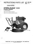
1
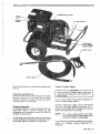
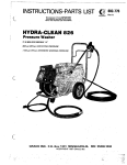
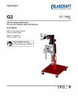
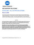
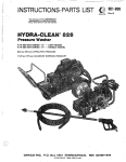
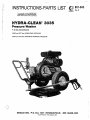
This manual contains IRllPORTAMT
V\IARMIMGS and INSTRUCTIONS
READ AND RETAIN FOR REFERENCE
PIN 800-065 SERIES B
._
3000 psi (207 bar) OPERATING PRESSURE
3400 psi 1234 bar) MAXIMUM WORKING PRESSURE
c._
..,. . .:I.
j. ::
. ~.
@.
B.0.50x .l44)1
NEEQBPOUS.
OCOPYRIGHT 1984 GRACO INC.
!55"14&3
%i FBWE
INJECTION HAZARD
Fluids under high pressure from spray or leaks can
penetratetheskinandcauseextremelyserious
injury, including the need for amputation.
Do not spray flammable liquids. Do not operate the
.engine where combustible fumes
or dust may be
present.
NEVER point the spray gun at anyoneor any part of
the body.
G A S ENQIINE PRECAUTIONS
NEVER put hand or fingers over the spray tip.
NEVER fill fuel tank while engine is running or hot.
Avoid the possibility of spilled fuel causing a fire.
Always refuel slowly to avoid spillage.
NEVER try to stop or deflect leak$with your.hand or
body.
ALWAYS have the tip guard in place when spraying.
MEDICAL TREATMENBi
Ifanyfluid
appears topenetrateyour
skin,get
E M E R G E N C Y M E D I C A L C A R E AT ONCE.
DO NOT TREAT AS A S I M P L E C U T .
Tell the doctor exactly what fluid was injected.
For
treatmentinstructionshaveyourdoctorcallthe
NATIONAL POISON CENTER NETWORK
($1 2)684-6669
~
NEVER operate enginein a closedbuilding unless the
exhaustispipedoutside.Theexhaustcontains
carbon monoxide, apoisonous. odorlessand invisible
gas, which, if breathed, may cause serious illness or
possibly death.
NEVER make adjustments on machinery while it is
connected to the engine; first remove the ignition
cable
from
the
spark plug.
Turning
over
the
machinery by handduringadjustingorcleaning
might.starttheengineandmachinery.causing
serious injury to the operator.
NEVER run the engine with governordisconnected,
or operate a t speeds in excess of 3600 RPM load:
AVOID COMPONENT RUPTURE
Even after you shut off the gasoline engine, there is
high p.ressure in the pump, hose and gun'until you
release it by triggering the gun. So before removing
the spray tip or servicing the unit, always shut offthe
unit and trigger the gun to release pressure.
Be sure
that
all
accessory
items
and
system
components will withstand the pressure developed,
of any component
NEVER exceed the pressure rating
in system.,NEVER alter or modify equipment -your
ofthe
personal safety, as well as thefunction
pressure
equipment, isatstake. Maximum working
3400 PSI (234 bar).
accident.
Precaution is the best insurance against an
When starting the engine, maintain a safe distance
.
.
from
moving
parts
of.the
equipment.
G
E
~
~
R
~
~
~
~
NEVER run the unit with the.belt guard
removed.
Keep clear of moving parts when the unit is running.
Before each use, check hose
for weak, worn ordamaged
conditions caused by traffic, sharp corners, pinching or
kinking.Tightenall fluid connectionssecurelybefore
each use. Replace any damaged hose.
O b s e r vdee t e r g e nmt a n u f a c t u r e r s' sa f e t y
precautions. Avoid~getting detergentor other liquids
in your eyes. Follow the directions on the.container
with eyes,, nose, and skin,
regarding
conract
breathing fumes, etc: Always wear full goggles to
protect your eyes from the sprayas well as any debris
dislodged by the spray. If necessary, wear gloves or
other protective clothing. If antidotes or treatment
are recommended,.be prepared to use them.
Do not usechemicalsoragentswhich are not compatible
with Buna-N and PIC or neoprene cover'of hose.
DON'T spray toxic chemicals such as insecticide or
weed killer.
Do not leave a oressurizedunit unattended. Shutoff the
unit and release pressure before leaving.
~~~
~
IMPORTANT
..
,
United States Government safety standards have been adopted under the Occupational Safety and Health Act.
These standards - particularly the GeneralStandards, Part 1910, and the Construction Standards, Part1926should be consulted in connection with your use of airless spray equipment,
..
2
801-643
Refer to the engine instruction booklet provided with
the unit.
Install Hose and SprayGun
Connect the spray hose to-thespray gun by inserting
thepin
at theendofthehoseintothequick
disconnect coupler on the gun. Connect the hose to
the fluid outlet in the same way.
..
CleaningAccessories
For spraying.detergent or other cleaning solution,
we
recommend.usingachemicalinjectorkit,
See
Accessories andinstructionmanual801-645for
installation and operation.
~
..
.
'
'
':.
..
.. .'
For removing rust and old paint we recommend using
a water sandblaster. See Accessories and instruction
manual 801-646 for installation and operation.
Connect To Water Supply
Do not exceed 160°F (7OoC) water.temperature to
pump in a direct supply system.
Connect a hose with at least a 3/4 in. (19 mm) ID
from your city water supply
to the unit's 314 in.
garden hose threaded inlet. The supply hose should
.not be more than 5 0 ft. (15 m) long.
MOTE:
Fora directsupply .system.your water
source at theunit must have a flow rate
of
A T LEAST.5 GPM (19 LITER/MIMI.
If you: operating conditions are different from
above.
contact ourCustomerService
Departmentfor
assistance.
,
801-643
3
.
__
..
,
OPERATION
Startup
Before starting, be sure to read the safety warnings and
setup instructions.
When shutting .down for the day or weekend, shut off
unit, shut off watersupply valve, andtriggergun to
release pressure. Wipe off the unit with a damp rag.
Check the oil'and gasoline levels daily.
-
CAUTION
Shut off cleaning unit when not actuallyspraying,
for longer pump life.The pump will overheat ifleft
running for over 10 minutes without spraying.
Turn on the water supply.
Trigger the gun to release any back pressure
Check the filter screen in the water inlet connection as
often as necessary, at least daily. Do not operate the
unit with the inlet and filter screen removed.
DO NOT try to adjust the unloadervalve or change the
engine speed. Changing these settings may
cause excessive pressure, intermittent unloader operation, wastedfuel
and increased wear on parts and will void the warranty.
Set the choke and open the fuel valve.
NOTE:
Foreasier starting, hold the gun trigger open
while pulling the rope.
Put your~footon the frame or wheel to steady the unit
when you pull the starter rope. Hold the gun
in your lefi
hand with the trigger open while starting the engine.
Grasp the starter rope grip and rapidly pull out the cord
two or three feet (1 m). Repeat if necessary with the
choke opened slightly. Whentheengine
starts, immediately release theguntrigger.
Open the .choke
gradually.
I
PUMP MUST NOT BE RUN DRY and must be drained
of water priorto exposure to freezing temperatures.Use
subjected to
and store theunit where it willnotbe
freezing temperatures. If water does freeze in the unit,
thaw before trying to start. A 50% anti-freeze solution
may be pumped prior to cold weather storage.
Use only spray tips that are matched to theunit to avoid
excessive cycling and wear of the unloader valve. See
ACCESSORIES.
CAUTION
Never run the cleaning unit dry. Costly damage to
the pumpwill result. Always be sure watersupply
is completely turned on before operating.
Inspect all connections for any
leaks.
necessary.
Tighten
if
Cleaning
For Hydra-Clean technique, see the Chemical Injector
manual, 801 -645.
For abrasive cleaning, see theWaterSandblaster
manual, 801-646.
WARNING
Follow these precautions when removing and installing nozzles:
1. . Shut off the cleaning unit and trigger the gun
to relieve pressure. Engage the trigger safety.
2.
Keep. the nozzleand thetubepointedaway
from you and everyone else.
3. Do not put your hand over the tip to push the
nozzle into place. Grasp it from the side and
keep your fingers away from the tip.
4.
Do not let anyone else touch the spray valve
while you are cleaning nozzles.
5.
Be sure the slip ring is pushed forward to lock
the nozzle in place before triggering thespray
gun.
Shutdown and Care Of Unit
When unit is not in use, turn off water supply
4
801-643
I
temperature
change
may
plungers.
crack the ceramic
~
~~
I
~
Do not pump caustic materials.
Before extended storage, flush the pump with light oil.
Avoid dragging hose over an abrasive surface such as
cement. This causes ex.cessive wear and shorter hose
life.
Clean the intake line strainer daily.
Lubrication and Care
100 hours of operaChange the engine oil after every
tion. Drain oil with.engine warm. Engine requires 3
pints (1.4 liters) 3 0 W oil. See separate instruction
manual for maintenance procedures.
Fill pump crankcase to dot on oil.gauge window with
34 oz. (1.0 liters)of crankcase oil (part no. 801-144)
or equivalent SA€ 40 weight hydraulic oil with anti-
.
wear and rust inhibitor additives. Change initial fill
after 50 hour running period. Change oil every 3
months or at 500 hour intervals.
valve.
Altering or adjusting unloader willnot increase
performance of unit,
st
be
performed
only by
,.
, . .
~
. .
.
SERVICE
TROUBLESHOOTING
~~
PROBLEM
CAUSE
Engine Will Not Start
Or Hard To Start.
No gasoline in fuel tank or
carburetor,
SOLUTION
Fill the tank with gasoline, open fuel shut-of
valve.
l Check fuel line and carburetor.
Drain fuel tank and carburetor. Use new fu
and dry spark plug.
Open choke and crank engine several times
clear out the gas.
Remove and clean.
Clean, adjust the gap or replace
Water in gasoline or old fuel.
Choked improperly. Flooded
engine.
Dirty carburetor air filter.
Spark plug dirty or improper
gap.
Spray gun closed.
ngine Misses Or Lacks
ower
Partially plugged air filter,
Spark plug dirty, wrong gap,
or wrong type.
Incorrect ignition timing.
~~
ow Pressure
Worn nozzle.
Belt slippage.
Trigger spray gun
Remove and clean.
Clean. adjust the gap, or replace.
I
Time engine.
Replace with nozzle of proper size
Tighten or replace;use correct belts and replac
both at same time.
Disassemble, reseal, and reassemble.
Clean, and adjust relief valve; check for wor,
and dirty valve seats. Kit available.
Air leak in inlet plumbing.
Relief valve stuck, partially
plugged or improperly
adjusted; valve seat worn.
Inlet suction strainer clogged or Clean. Use adequate size. Check more
improper size.
frequently.
WornpackinAbrasives,
in
Install proper filter. Check flow available to
pumped fluidgbr severe cavita- pump.
tion. Inadequate water supply.
Fouled or dirty inlet or discharge
Clean inlet and discharge valve assemblies.
valves.
Worn inlet or discharge valves. Replace worn valves, valve seats and/or
Leakv discharae hose
jischarge hose.
lrmp runs extremely rough,
'essure low.
Restricted inlet or air entering
the inlet plumbing.
nlet restrictions and/or air
eaks. Stuck inlet or discharge
lalve..
-caking H.P. seals.
I'roper size inlet plumbing; check for air tigh
!seal:
I:lean out foreign material, replace
worn valves
Replace seals
~
~~
~~~
~~~
rater leaka e from under
e rnanifod
Norn packing.
later in pump crankcase.
May be caused by humid,air
Change oil at 3 month or 500 Hour intervals usin(
:ondensing into water lnslde I the
Crankcase Oil (otherap roved oil every month 01
:rankcase.
?OO hours) P.N. 801-r44.
equent orprematurefailurc
the packing.
Scored plungers.
h e r pressure to inlet manifold.
lamaged or worn plungers.
ibrasivematerial in thefluid
leing pumped.
Lxcessive pressure and/or
emperature of fluid being
lumped.
h e r pressure
pumps.
of Reduce
pressure.
lunning
pump
dry.
rong surging at the inlet
d low pressure on the
;charge side.
I nstall. newpacking.
-
I
oreign particles in the inlet or
ischarge valve, or worn inlet
nd/or discharge valves.
Isplace plungers.
leduce inlet pressure
leplace plungers.
properfiltration on pumpinletplumbing
Check pressures and fluid inlet temperature;
be
sure they are within specified range.
Do not
run
pump
without
water.
Check for smooth lap surfaces on inlet and
dischar e valve seats. Discharge valve seats and
Inlet va ve seats maybe 1appe.don a veryflne
011
stone.
9
801-643
5
PARTS DRAWING
Pressure Washer Assembly, 800-065
2 0 - y
42%
''7
6
801-643
"-
~
-.
-
.
PARTS LIST
Pressure Washer Assembly. 800-065
REF. PART
I,
\.
.
DESCRIPTION
NO. NO.
1
GUN ASSEMBLY. see parts
drawing/list page 10
TIP. 0004 MEG, 1/4 thd., Oo
TIP, 1504 MEG. 1/4 thd., 15O
PUMP ASSEMBLY. see Darts
drawing/list page 9
ENGINE, 11 h.p.
CHASSIS WELDMENT
BOOT. lea
BELT,.dri;e
NIPPLE, hex, 3/8 x 3/8 NPT
LABEL warning
LABEL, warning
DECAL, GracoNangard
PLATE. serial no.
SCREW, hex, 5/16-18 x 1 - 3 / 4
SCREW. hex, 5/16-18 x 1"
SCREW, hex, 5/16-18 x 3"
SCREW. hex, 3/8-16 x 7"
SCREW, hex, 3/8-16 x 1-1/4"
SCREW, hex. M8 x 30 MM
WASHER, flat, 5/16
WASHER, flat, 1/4
WASHER, lock. 3/8
WASHER, lock. 5/16
NUT,hex. 5/16-18
NUT, locking, 3/8-16
NUT, locking. 1/2-13
GROMMET
HOSE, H.P.. 3/8 x 50 ft.
PULLEY, pump
PULLEY. enaine
HUB. pilley"
HUB. pulley
QUICKCOUPLE.male, 3/8
QUICK COUPLE. female. 3/8
HANDLE
800-130
2 "801 -599
3 '801 -600
4 800-068
5
6
7
8
9
10
11
12
13
14
15
16
17
18
19
20
21
22
23
24
25
26
27
28
29
30
31
32
33
34
35
801 -283
800-067
801-506
801 -003
801 -603
801-141
801-129
801 -543
801-131
801 -022
801-941
801 -942
801.531
801.546
801.559
801 -015
801-023
801-363
801 -025
801 -024
801 -499
801 -020
801 -548
801-571
801 -004
801-911
801-135
801-376
*801-568
*801-569
801-541
QTY.
1
1
1
REF. PART
NO. NO.
36
37
38
39
40
1
1
1
1
2
1
1
1
1
1
4
7
1
1
4
4
5
24
4
20
11
1
2
5
1
1
1
1
1
1
2
.-
41
42
43
44
45
46
47
48
49
50
51
52
53
54
55
56
57
58
59
60
61
62
63
64
65
66
601-3154
801-500
801 -539
801 -505
801 -537
801-556
801-504
801-593
801-550
"801-601
"801-602
801-132
801-130
801-610
801-608
801-605
801-875
801-606
801-367
801-612
801-676
801-090
801 -922
800-156
801-940
801-555
801-521
801-520
801-927
801-137
801-731
an.
DESCRIPTION
BELTGUARD COVER
BELTGUARD BASE
BUMPER
FOOT RETAINER
WELDMENT, leg suppon
.AX1
..." F
FOOT
SPRING. 6"
WHEEL
TIP, 2504 MEG, 1/4 thd., 25O
TIP. 4004 MEG, 1/4 thd.. 40°
RIVET, drive
LABEL. warning
BRACKET, support
PIN. roll
SCREW, hex, #lo-24 x 3/4
WASHER, lock, #lo
WASHER.. flat.. 3/16
BUMPER
WASHER, flat, 7/16
SPACER, beltguard
QUICK COUPLE, female thd.
NUT. adjusting
NUT. weldment
SCREW, hex. 5/16-18 x 3/4
LABEL; chk. oil
RAIL STIFFNER WELDMENT
RAILSTIFFNERBRACKET
LABEL, Model 3035
~~
1
1
1
1
1
1
1
1
2
1
1
2
1
1
1
1
1
1
1
2
4
4
3
1
,1
1
1
1
1
1
2
KEY
BUMPER
Order parrs by name and series'lerrer of the assembly for
which you are ordering.
"Recommended "roo1 box" spare parrs.
1
PARTS DRAWING
Unloader Asse
3000 PSI (207 bar)
REF. PART
NO. NO.
801-045
L
7
9
10
11
12
13
14
15
16
17
801-046
801-047
801 -048
801-049
801-050
800-123
801-059
801-412
801-432
801-062
801 -063
801-068
801-069
801-070
801-071
801-939
DESCRIPTION
CAGE,
valve
O-RING
SPRING
BALL
SEAT
O-RING
UNLOADER SUB-ASSEMBLY
O-RING
HOUSING
CYLINDER
O-RING
PLUG
HOUSING VALVE
1
2
1
1
1
1
1
VALVE
2
1
1
1
SEAT
1
O-RING
1
SPRING
Order parrs b y name and series letter of the assembly for
which you are ordering.
801-643
7
Pump (Refer to Parts Drawing, 'Page 9)
NOTE:
Two sizes of metric wrenchesare necessary
for servicing the pump; M13 and M30.
Valves:
1. Remove the hex plug (5)from manifold (6) using
M30
wrench.
8. Lubricate each plunger and carefully slide manifold
onto crankcase.
9.Replace the eightcapscrewsand
Torque to 21.7 ft. Ibs. (3 K/m).
snugthemup.
NOTE: The eightcapscrews
2. Examine O-ring (4) under plug.and replace if cutsor
distortion exist.
3. Remove valve unit and O-ring (3) from cavity
NOTE: Valve unit maycomeapartduringremoval.
must betorqued
evenlyto
apply equalpressure
onthe
manifold so that it seatsproperlyand
doesn't bind or jam. This is best done by
torquing bolts closest to the center of the
manifoid first and then working out from
those bolts.
4. Replace valve unit with P/N 801 -472
Servicing V-Packings:
to 75ft. Ibs. (1 0.3 K/m).
5. Replace hex plug and torque
NOTE: Use packing repair kit P/N 801 -486
NOTE: Hex plug shouldbere-torqued.after5
hours operation.
.
.
Pumping Section:
1. Remove the eight cap screws (I)
from the manifold
using the M13 wrench.
2. Carefully separate the manifold from the
crankcase.
NOTE:
It may be necessary to tap manifold lightly
with mallet to loosen.
1 . Afterremovingtheeightcapscrews
.andthe
manifold carefully pull packing
retainer(l9)from the
manifold.
Examine
O-ring
(10) and replace if
necessary.
2. Remove low pressure packing (8) and head ring (7).
3. Pull intermediate retainer ring (20) from manifold.
high pressure packing (8)
Remove long life ring (9).
and head ring (7).
4. Inspect all parts and replace if necessary
plungerswhenremoving
nlungers or seals.
to avoiddamageto
NOTE: If just the packings are needed use kit801 486. If rings or retainers need replacement
use kit 801 -487.
3. Carefully examine each plunger(16) for any scoring
and replace if necessary.
5. Thoroughly clean packing cavity in manifold and
examine. Lightly grease packing cavity.
Servicing Plungers:
1. Loosen plunger retaining screw(l2)5-6turns,using
"10 wrench.Pushplungertowardscrankcase.
Ttiis will separate plunger and retaining screw.
6.Replace packing assembly in the following order:
2. Remove retaining screw from plunger andexamine
O-ring (18). back-up ring (17). and copper
bearing/gasket washer (13). Replace if necessary
using plunger repair kit P/N 801 -474.
3. Removeplunger
fromplunger
rod and remove
copper flinger (15). Clean or replace if necessary.
4. Lightly grease flinger and replaceit on plunger rod.
5 . Replace plunger
6. Lightly grease retaining screw assembly
to avoid
cutting O-ring. Lightly grease outer end of plunger.
7. Install retaining screw assembly into plunger and
torque to 14.4 ft. Ibs. (2 K/m).
8
801-643
(7). packing (8).long life
ring
(9).
head
ring
intermediatering (20). head ring (7). packing(8).
packing retainer (1 9).and O-ring (10).
CAUTION
Carefully study the location of each part and the
position of the seals to assure proper reassembly
and operation.
7. Lubricate each plunger and carefully slide manifold
onto crankcase:
NOTE: When
replacing
the
manifold
onto
plungers,
extreme
caution
should
be
exercised to avoid damage to the seals.
8. Replace the eight capscrews in the manifold and
9 under
tighten as previously
described
(step
servicing plungers).
. .
PART§ DRAWING
UNLOADER ASSEMBLY
PACKING & RETAINER
KIT 801-487.
PLUNGER
REPAIR
KIT 801 -474
Includes:
VALVE UNIT
KIT 801-472
OIL SEAL KIT
801 -473
PACKING KIT
801 -486
Includes: Includes: Includes:
REF.
REF.
NO.
3
aTy.
6
NO.
QTY.
11
3
REF.
an.
NO.
8
6
REF.
NO.
12
13
17
18
QTY.
3
3
3
3
(Three kits needed
for entire pump.)
Includes:
REF.
NO.
QTY.
2
2
1
1
1
1
7
8
9
10
19
20
PARTS LIST
Pump Assembly, 800-068
REF. PART
NO. NO.
1 801-468
2
3
4
6
6
7
.
.
.i
\
801-469
801-852
801-470
801-648
801.647
801-479
8
801-478
9 801-481
10 801.476
1 i 801-777
12 801-493
13 801-492
14 801-475
15 801.489
16 801-490
17 801-491
18 801-488
19 801-477
20801-480
21
801-484
22
801-482
DESCRIPTION
SCREW, M8 x 70 mm
WASHER
VALVE UNIT
O-RING
HEXPLUG, M24 x 2 x 16
MANIFOLD
HEAD RING
PACKING
LONGLIFERING
PLUNGERRETAININGSCREW
BEARING/GASKET WASHER
OIL DIPSTICK
FLINGER
PLUNGER
BACK-UP RING
O-RING
PACKINGRETAINER
INTERMEDIATE RING
CAP, 318 NPT
CAP, 112 NPT
REF. PART
QTY
DESCRIPTION
NO. NO.
8
801-485
8
6
6
6
1
6
6
3
3
3
3
3
1
3
3
3
3
3
3
1
1
23 801-483
24
25 801-107
26 801-523
27
801.106
28 801-110
29
801-111
30801-112
31 801-597
32 800-122
ON
WASHER
WASHER
REDUCING
NIPPLE,
1/2 x 318
NIPPLE, 1/2 NPT x 2"
TEE, 112 NPT
HOSE ADAPTER
HOSECONN.NUT
INLET SCREEN
HOSE, low pressure
UNLOADER ASSEMBLY. see
1
1
1
1
pans drawing/list. page 7
QUICKCOUPLE, male, 3/8
33 801-568
TENSIONER. belt
34801-526
NIPPLE, 3/4 NPT X G 3 ~ esp
3
35 801-913
PUMP
36801-899
PLUG, plastic
37801-910
WASHER, aluminum
38
801.907
39801-143
TAG, caution
40801-524
LABEL, pump.
Order Dartsbv name andseries letter of the assembly for
'
which you ere ordering.
801-643 9
NOTE: Hose. Quick Couplers
E Spray Tips not included
with Gun Assembly - See
Pressure Washer Assembly
Parts Drawing/List. page 6 . 1.
Gun Assembly, 800-130
REF. PART
NO.
SERVICE
Gun, Cartridge Replacement
NO.
1
2
3
4
DESCRIPTION
TUBE. 32"
GRIP
801-134
801-674
801-009
801-638
COUPLER,female quick disconnect
'SPRAY
GUN,
(replaceable
pans include items 5-18)
. CARTRIDGE
. HOUSING
. HEX PLUG
. TRIGGERPIN
. TRIGGER
. OUTLET
. PINCOVER
ACCESSPIN
. HANDLE
. ACCESS
PLATE
. TUBE
. INLET FllTING
O-RING,
quick
couple
OW
1
1
1
1
1
801-639
1. Press accesspin (12) from gun handle and remove
1
6 801-671
access plate(14)byslidingplatebackwards.
1
7 801-670
Remove cartridge (5)from housing (6) by using a
1
8 801-256
19 mm socket wrench.
9 801-424
1
1
10 801-672
2
801-673
11
2. CheclCinside housing to be sure all O-rings came
1
12 801.428
out when cartridge was removed. If O-ring can be
801-419
13
1
seen inside the housing, remove it, being careful
1
14 801-427
not to damage internal threads in housing.
15 . 801-420
1
1
16 801-423
3. Throw away old cartridge and install new cartridge 17 '801-202
1
using a small amount of pipe sealant on threads.
Order parts by name and series lerrer of rhe assembly for
Be sure totighten cartridgefirmlyagainst housing.
5
'
which you are ordering.
4. Slide access plate into place and install
access pin.
10 801-643
*Recommended "roo1 box" spare parts.
.
,
. .
ACCESSORBES (Must be purchased separately)
,
. :.
@J&vg&g#.>;:.:
CHEIWICAL'IMJECTQWKIT 800-987
WATER SANDBLASTER 800-120
For injecting harsh cleaning chemicals downstream
from pump.
For abrasivecleaning of stubborndirt
Spray tip not included in kit.
BACK FLOW PREVENTOR 801-133
~
~
~ SPRAY
~ TIP 801-600
5
~
Preventback-up of contaminated water into fresh
supply. Install upstream from pump.
UECHMlCAb DAUA
ENGINE: WlSC
4 cycle. single cylinder.
air cwled. 11 hp
GASOLiNE TANK:
6.2 quarts (6 liter)
capacity
WATER PUMP: 3000 PSI (207bar)max.
pressure: 3.5 GPM
113.25 liter/min).
W E T E D PARTS: StainlessSteel, Aluminum.
Phenolic Plastic, Ceramic
Liners. Nitrile Rubber.
UNIT WEIGHT: 222 Ib (101 kg)
OVERALL DIMENSION: Length: W (1 1 I 8 mm)
Width: 31" (787 mm)
Height: 28" (711 mm)
MAX. WATER TEMPERATURE:
INLET HOSE CONNECTION
160" (70° Cl
3 / 4 garden hose
(f)
andpaint.
$
T
..
THE GRACO WARRANTY
GracoInc.warrantsallequipmentmanufacturadbyitandbearingitsnametobefreefromdefectsin
material and workmanship under normal use and seivice. This warranty extends to the original
p"r~haserforaperiodof12monthsfromthedateofpurchaseandappliasonlywhentheequipment
is installed and operated
in accordance with written factory recommendations. This warranty
does
not cover damage or wear which. in the reasonablejudgment of Graco. a w e s from misuse.
abrasion, corrosion. negligence, accident. substitution of nun-Graco parts. faulty installation or
tampering.
This warranty is conditioned upon the prepaid return
of the equipment claimedto be defective for
exammation by Graco to verify the claimed defect.
Ifthe claimed defectis verified. Graco will repalr
or replace free of charge. any defective pans. The equipment will be returned to the original
purchaser transportation prepaid. If inspection of the equipment does not disclose any defectin
wofkmanshipor material. r e p a n w i l l b e m a d e a t areasanablechargeand returntransportationwill
be charged.
THIS LIMITED WARRANTY IS EXCLUSIVE.ANDISIN LIEU OF ANY OTHER WA~RANTIESIEXPRESS
OR IMPLIED) INCLUDING WARRANTY OF MERCHANTABILITY OR WARRANTY OF FITNESS FOR A
PARTICULAR PURPOSE AND OFANY NON-CONTRACTUAL LIABILITIES INCLUDING PRODUCT
LIABILITIES BASED ON NEGLIGENCE OR STRICT LIABILIM. EVERY FORM OF LIABILITY FOR
DIRECT.SPECIAL OR CONSEOUENTIAL DAMAGES OR'LOSS IS EXPRESSLYEXCLUDED AND
DENIED.
EOUIPMENT NOT COVERED BY GRACO WARRANTY. Accessories or components of equipment
not manufactured by Graco (such
as electric motors. switches. hose.etc.)are
sold by Graco that are
subject to the warranty. if any. of their manufacturer. Graeo will prawde purchaser with reasonable
assistance in making such claims.
Factory Branches: Atlanta. Dallas, Detroit. Loa Angelar. West Caldwell IN.J.1
Subsidiary and Affiliate Companies: Canada; England; Switzerland; ~ r a n c e ~: e r m a n y ;Hang ~ o n g ~
; apan
GRACO INC.
B.Q. BOX 1441 MIIINIRIEAPOLRS, MSul 55440-'144.4
PRINTED IN U.S.A.45-10060
801
4/85
-643
REV D