1
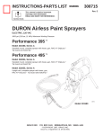
INSTRUCTIONS-PARTS LIST
This manual contains important
warnings and information.
READ AND RETAIN FOR REFERENCE
308237
Rev E
Supersedes B and PCN E
Silver Circulating
Airless Spray Gun
5000 psi (345 bar) Maximum Working Pressure
Model 235465, Series B
Includes the Standard (nonĆreversing) DripLesst
Tip Guard and 2 finger trigger.
Spray tip not included; order separately.
II 2 G
Patents Pending
INDEX
Warnings . . . . . . . . . . . . . . . . . . . . . . . . . . . . . . . . . 2
Installation/Operation . . . . . . . . . . . . . . . . . . . . . . . 4
ąSystem Requirements . . . . . . . . . . . . . . . . . . . . 4
ąHow to Use the Trigger Safety Latch . . . . . . . . 4
ąHow to Use the Gun . . . . . . . . . . . . . . . . . . . . . . 4
ąHow to Adjust the Spray Pattern . . . . . . . . . . . . 5
ąHow to Clean the Spray Tip
ąąand Clear a Spray Tip Obstruction . . . . . . . . 5
ąHow to Flush the Gun . . . . . . . . . . . . . . . . . . . . 6
ServiceĂ . . . . . . . . . . . . . . . . . . . . . . . . . . . . . . . . . . 7
PartsĂ . . . . . . . . . . . . . . . . . . . . . . . . . . . . . . . . . . . . 8
AccessoriesĂ . . . . . . . . . . . . . . . . . . . . . . . . . . . . . 10
Technical DataĂ . . . . . . . . . . . . . . . . . . . . . . . . . . . 11
Graco Phone Numbers . . . . . . . . . . . . . . . . . . . . 11
Warranty . . . . . . . . . . . . . . . . . . . . . . . . . . . . . . . . 11
GRACO INC.ąP.O. BOX 1441ąMINNEAPOLIS, MNą55440-1441
ECOPYRIGHT 1992, GRACO INC.
01482
WARNINGS
High Pressure Spray Can Cause Serious Injury. For Professional Use Only.
Observe All Warnings. Read and understand all instruction manuals before operating equipment.
FLUID INJECTION HAZARD
General Safety
This equipment generates very high fluid pressure. Spray from
the gun, leaks or ruptured components can inject fluid through
your skin and into your body, and cause extremely serious injury,
including the need for amputation. Also, fluid injected or
splashed into the eyes or on the skin can cause serious damage.
NEVER point the spray gun at any one or at any part of the body.
NEVER put your hand or fingers over the spray tip. NEVER try
to blow back" paint; this is not an air spray system.
ALWAYS have the tip guard in place on the spray gun when
spraying.
ALWAYS follow the PRESSURE RELIEF PROCEDURE, below,
before cleaning or removing the spray tip or servicing any sysĆ
tem equipment.
NEVER try to stop or deflect leaks with your hand or body.
Be sure equipment safety devices are operating properly before
each use.
Medical Alert--Airless Spray Wounds
If any fluid appears to penetrate your skin, get EMERGENCY
MEDICAL CARE AT ONCE. DO NOT TREAT AS A SIMPLE
CUT. Tell the doctor exactly what fluid was injected.
Note to Physician: Injection in the skin is a traumatic injury. It
is important to treat the injury surgically as soon as possible. Do
not delay treatment to research toxicity. Toxicity is a concern
with some exotic coatings injected directly into the blood stream.
Consultation with a plastic surgeon or reconstructive hand surĆ
geon may be advisable.
Spray Gun Safety Devices
This gun has several safety devices. Be sure all of them are operĆ
ating properly before each use. Do not remove or modify any
part of the gun; this can cause a malfunction and result in serious
injury.
Whenever you stop spraying, even for a moment, always set the
trigger safety latch in the engaged or safe" position, making the
gun inoperative. Failure to set the trigger safety latch can result
in accidental triggering of the gun. See Fig. 1.
ALWAYS have the tip guard in place on the spray gun while
spraying. The tip guard alerts you to the fluid injection hazard
and helps reduce, but does not prevent, the risk of accidentally
placing your fingers or any part of your body close to the spray
tip. See Fig. 2.
Always have the trigger guard in place on the gun when spraying
to reduce the risk of accidentally triggering the gun if it is
dropped or bumped. The fluid housing and heat shield act as a
trigger guard for this gun. See Fig. 2.
2
308237
Spray Tip Safety
Use extreme caution when cleaning or changing spray tips. If the
spray tip clogs while spraying, engage the trigger safety latch
immediately. ALWAYS follow the PRESSURE RELIEF PROCEĆ
DURE, below, and then remove the spray tip to clean it.
NEVER wipe off build-up around the spray tip until the pressure
is fully relieved and the gun safety is engageed.
Pressure Relief Procedure
To reduce the risk of serious bodily injury, including fluid
injection, splashing fluid or solvent in the eyes or on the
skin, or injury from moving parts or electric shock, always
follow this procedure whenever you shut off the sprayer,
when checking or servicing any part of the spray system,
when installing, cleaning or changing spray tips, and
whenever you stop spraying.
. Engage the trigger safety latch.
. Shut off the power supply to the pump and close any
bleedĆtype master air valves.
. Disengage the trigger safety latch. Hold a metal part of
the gun firmly to the side of a grounded metal pail, and
trigger the gun to relieve pressure.
. Engage the trigger safety latch.
. Open the pressure drain valve (required in system),
having a container ready to catch the drainage. Leave
the valve open until you are ready to spray again.
If you suspect that the spray tip or hose is completely
clogged, or that pressure has not been fully relieved after
following the steps above, VERY SLOWLY loosen the tip
guard retaining nut or hose end coupling to relieve presĆ
sure gradually, then loosen completely. Now clear the tip
or hose.
MOVING PARTS HAZARD
Moving parts can pinch or amputate your fingers or other body
parts. KEEP CLEAR of moving parts when starting or operating
the sprayer. Follow the Pressure Relief Procedure, above, beĆ
fore checking or servicing any part of the sprayer, to prevent it
from starting accidentally.
RECOIL HAZARD
Due to the high pressure fluid emitted, a strong recoil action may
occur when you trigger this gun. If you are unprepared, your
hand could be forced back toward your body or you could lose
your balance and fall, resulting in serious injury.
EQUIPMENT MISUSE HAZARD
General Safety
Any misuse of the spray equipment or accessories, such as
overpressurizing, modifying parts, using incompatible chemiĆ
cals and fluids, or using worn or damaged parts, can cause them
to rupture and result in fluid injection, splashing in the eyes or on
the skin, or other serious bodily injury, or fire, explosion or propĆ
erty damage.
NEVER alter or modify any part of this equipment; doing so
could cause it to malfunction.
CHECK all spray equipment regularly and repair or replace worn
or damaged parts immediately.
Always wear protective eyewear, gloves, clothing and respirator
as recommended by the fluid and solvent manufacturer. Wear
hearing protection when operating this equipment.
System Pressure
Do not exceed 5000 psi (345 bar) Maximum Working Pressure
to the gun. Be sure all spray equipment and accessories used
are rated to withstand this pressure. Do not exceed the maxiĆ
mum working pressure of any component or accessory used in
the system.
Fluid and Solvent Compatibility
All chemicals used in the sprayer must be chemically compatible
with the wetted parts shown in the TECHNICAL DATA on the
back cover. Consult your chemical supplier to ensure compatiĆ
bility.
HOSE SAFETY
High pressure fluid in the hoses can be very dangerous. If the
hose develops a leak, split or rupture due to any kind of wear,
damage or misuse, the high pressure spray emitted from it can
cause a fluid injection injury or other serious bodily injury or
property damage.
All fluid hoses must have strain reliefs on both ends! The
strain reliefs help protect the hose from kinks or bends at or close
to the coupling which can result in hose rupture.
Tighten all fluid connections securely before each use. High
pressure fluid can dislodge a loose coupling or allow high presĆ
sure spray to be emitted from the coupling.
Never use a damaged hose. Before each use, check the entire
hose for cuts, leaks, abrasion, bulging cover, or damage or
movement of the hose couplings. If any of these conditions exist,
replace the hose immediately. Do not try to recouple high presĆ
sure hose or mend it with tape or any other device. A repaired
hose cannot contain the high pressure fluid.
Handle and route hoses carefully. Do not pull on hoses to move
equipment. Keep hoses clear of moving parts and hot surfaces
of the pump and power supply. Do not use fluids or solvents
which are not compatible with the inner tube and cover of the
hose. DO NOT expose Graco hoses to temperatures above 180_
F (82_ C) or below -40_ F (-40_ C).
Hose Grounding Continuity
Proper hose grounding continuity is essential to maintaining a
grounded spray system. Check the electrical resistance of your
fluid hoses at least once a week. If your hose does not have a tag
on it which specifies the maximum electrical resistance, contact
the hose supplier or manufacturer for the maximum resistance
limits. Use a resistance meter in the appropriate range for your
hose to check the resistance. If the resistance exceeds the recĆ
ommended limits, replace it immediately. An ungrounded or
poorly grounded hose can make your system hazardous. Also
read FIRE OR EXPLOSION HAZARD, below.
FIRE OR EXPLOSION HAZARD
Static electricity is created by the flow of fluid through the pump
and hose. If every part of the spray equipment is not properly
grounded, sparking may occur, and the system may become
hazardous. Sparking may also occur when plugging in or unĆ
plugging a power supply cord or using a gasoline engine.
Sparks can ignite fumes from solvents and the fluid being
sprayed, dust particles and other flammable substances,
whether you are spraying indoors or outdoors, and can cause
a fire or explosion and serious bodily injury and property damĆ
age. Do not plug in or unplug any power supply cords in the
spray area when there is any chance of igniting fumes still in the
air.
If you experience any static sparking or even a slight shock while
using this equipment, stop spraying immediately. Check the
entire system for proper grounding. Do not use the system again
until the problem has been identified and corrected.
Grounding
To reduce the risk of static sparking, ground the sprayer and all
other spray equipment used or located in the spray area. Check
your local electrical code for detailed grounding instructions for
your area and type of equipment. Be sure to ground all of this
spray equipment:
. Pump or Sprayer: provide appropriate grounding as recomĆ
mended in your pump or sprayer instruction manual.
. Fluid hoses: use only grounded hoses with a maximum of
500 ft (150 m) combined hose length to ensure grounding
continuity. See Hose Grounding Continuity, above.
. Spray gun: obtain grounding through connection to a propĆ
erly grounded fluid hose and sprayer.
. Object being sprayed: according to local code.
. Fluid supply container: according to local code.
. All solvent pails used when flushing, according to local code.
Use only metal pails, which are conductive. Do not place the
pail on a non-conductive surface, such as paper or cardĆ
board, which interrupts the grounding continuity.
. To maintain grounding continuity when flushing or relieving
pressure, always hold a metal part of the gun firmly to the side
of a grounded metal pail, then trigger the gun.
Flushing Safety
To reduce the risk of fluid injection injury, static sparking, or
splashing, be sure the system is properly grounded, relieve
pressure, remove spray tip. Hold a metal part of the gun firmly
to the side of a grounded metal pail and use the lowest possible
fluid pressure during flushing.
IMPORTANT
United States Government safety standards have been adopted under the Occupational Safety and Health Act. These standards particularly the General Standards, Part 1910, and the Construction Standards, Part 1926 - should be consulted.
308237
3
Installation/Operation
System Requirements.
How to Use the Gun.
WARNING
Keep the walletĆsized warning card provided with
this gun with the operator at all times. The card
contains important treatment information should
an injection injury occur. Additional cards are
available at no charge from Graco Inc.
WARNING
Be sure your system has a bleedĆtype master air
valve (pneumatic pumps only) and a pressure
drain valve. These accessories help reduce the
risk of serious bodily injury, including fluid injecĆ
tion, splashing in the eyes or on the skin, or injury
from moving parts, if you are adjusting or repairing
the pump or gun.
1. The bleedĆtype master air valve (airĆpowered
pumps only) relieves air trapped between this
valve and the pump after the air regulator is shut
off. Trapped air can cause the pump to cycle
unexpectedly.
1. If an accessory inĆline filter is used, connect it to
the grounded fluid supply hose. Connect the
supply hose to one gun port and connect an elecĆ
trically conductive, fluid return hose to the other
port.
2. With no tip installed, start the pump. Flush the
pump according to the instructions supplied with
it. Prime the system with the fluid.
3. Follow the Pressure Relief Procedure on page
2. Be sure the trigger safety latch is engaged. See
Fig. 1.
4. Unscrew the tip guard (1) and install the tip (A)
and the gasket (2d) in the nut of the tip guard.
Screw the assembly firmly onto the gun. Tighten
the assembly with a wrench. See Fig. 2.
NOTE: If the gasket (2d) is not installed, the gun
will leak.
2. The pressure drain valve assists in relieving fluid
pressure in the displacement pump, hose and
gun: triggering the gun to relieve pressure may
not be sufficient.
1
A
2d
3. Strain the fluid you are spraying if it contains
particles which could clog the spray tip.
How to Use the Trigger Safety Latch
1. To engage the trigger safety latch, turn the latch
(A) to a right angle with the gun body. See Fig. 1.
2. To disengage the trigger safety latch, push the
latch (A) out and turn it parallel with the gun body.
ENGAGED
Fig. 2
01483
5. Start the pump.Adjust the back pressure valve or
the RestrictĆAĆFlo valve in the circulating system
return line. Adjust the fluid pressure until the
spray is completely atomized. Use the lowest
pressure necessary to get the desired results.
Higher pressure may not improve the spray
pattern and will cause premature tip wear and
pump wear.
6. If adjusting the pressure does not give a good
spray pattern, follow the Pressure Relief ProceĆ
dure on page 2 and then try another tip size.
DISENGAGED
Fig. 1
4
01484
308237
7. Use a fullĆopen, fullĆclose triggering action. Hold
the gun about 14 in. (350 mm) from and at right
angles to the work surface. Don't swing the gun
in an arc. Practice to find the best length and
speed of stroke.
How to Adjust the Spray Pattern.
1. Follow the Pressure Relief Procedure on page
2. Loosen the retaining nut (B). Turn the tip guard
so the groove in the tip is horizontal (C) for a horiĆ
zontal pattern and vertical (A) for a vertical
pattern. Tighten the retaining nut.
2. The orifice of the spray tip and the angle of the
spray pattern determines the coverage and the
size of the pattern. When more coverage is
needed, use a larger spray tip rather than
increasing the fluid pressure.
CAUTION
The openings in the tip guard reduce paint
buildup on the tip guard while spraying. Any
damage to the sharp edges of the openings
causes paint to collect at that area. Never hang
the gun by the tip guard.
How to Clean the Spray Tip
and Clear a Spray Tip Obstruction.
WARNING
To reduce the risk of fluid injection or splashing in
the eyes or on the skin, do not hold a hand, body
or rag in front of the spray tip when cleaning or
checking a clogged tip. Point the gun toward the
ground or into a waste container when checking
to see if the spray tip is cleared.
DO NOT try to blow back" paint; this is NOT an
air spray gun.
DO NOT wipe fluid buildup off the gun or spray tip
until pressure is relieved.
Cleaning during the day.
1. Follow the Pressure Relief Procedure, page 2.
2. Clean the front of the tip frequently during the day
to help reduce buildup. Also clean the tip and tip
guard at the end of each work day. Use a solventĆ
soaked brush to clean the spray tip.
Clearing an obstruction.
KEY
A
The tip guard is shown in the position for a
vertical spray pattern.
B
Retaining nut.
C
The tip guard is shown in the position for a
horizontal spray pattern.
Gun 235465 - with standard tip guard
1. Engage the trigger safety latch, open the presĆ
sure drain valve.
B
A
If the spray tip clogs while spraying, immediately stop
spraying, then:
C
2. Remove the spray tip and blow out the obstrucĆ
tion by applying air to the front of the spray tip.
Or, let the spray tip and gun nozzle soak to
dissolve the obstruction. If it won't dissolve, jar it
out by tapping the back of the spray tip against a
flat surface.
CAUTION
Fig. 3
Never soak the entire gun in solvent. Prolonged
exposure to solvent can ruin the packings.
Continued on page 6.
308237
5
Installation/Operation
If using the accessory RAC IV tip guard
1. Engage the trigger safety latch. Rotate the RAC IV
tip handle 180_. See Fig.4.
2. Disengage the safety latch. Trigger the gun into a
pail or onto the ground to remove the clog.
3. Engage the safety latch. Rotate the tip handle to
the spraying position.
4. If the tip is still clogged, engage the safety latch,
shut off the sprayer and disconnect the power
source, and open the pressure drain valve to reĆ
lieve pressure. Clean the spray tip as shown in
manual 307-848, supplied with the RAC IV.
KEY
A
Handle shown in
spraying position. Turn
handle 180° and
trigger gun to clear clog.
NOTE: If it is available, the flushing procedure
provided in your pump or sprayer manual should be
used instead of this procedure.
1. Follow the Pressure Relief Procedure, page 2.
2. Remove the tip guard and spray tip. Soak and
clean the parts.
3. Put the pump intake in a grounded pail of water
or solvent.
4. Start the pump at its lowest pressure.
5. Trigger the gun into the original pail. When
solvent appears, release the trigger.
6. With the gun trigger released, circulate the fluid
until the system is thoroughly flushed.
7. Follow the Pressure Relief Procedure, page 2.
WARNING
A
To reduce the risk of serious bodily injury,
including splashing fluid in the eyes or on the skin,
or static electric discharge when flushing:
Fig. 4
D Be sure the entire system, including flushing
pails, are properly grounded.
How to Flush the Gun.
D Remove the tip guard and spray tip.
WARNING
This gun uses a pre-orifice in the seat to
develop the type of spray pattern required in
most circulating systems. The preĆorifice does
not diffuse the spray from the nozzle into an
irregular pattern, as with the other airless spray
guns you may have used. Therefore, to reduce
the risk of an injection injury when the tip guard
is not installed, such as during cleaning, take
extra precautions to keep your hands and body
away from the nozzle of the gun.
Always flush the pump and the gun before the fluid
being sprayed can dry in it.
6
308237
D Maintain metal to metal contact between the
gun and the flushing pail.
D Use the lowest possible pressure.
ÂÂÂ
ÂÂÂ
ÂÂÂ
01485
Service
CAUTION
A
Do not attempt to install an old style needle in this
gun. The front of the new needle is marked with a
+ below the Graco symbol.
Fig. 7
Notes:
Use Needle Kit 235475.
Use all the new parts for the best results. Parts
included in the kit are shown with one asterisk, (2a*).
Keep parts very clean. Dried paint or other contamiĆ
nants cause friction which causes parts to wear faster.
Needle Replacement.
1. Follow the Pressure Relief Procedure, page 2.
2. Remove the hose, tip guard, spray tip and gasket.
B
2c
3. Remove the diffuser/seat (2a*) and gasket (2b*).
Remove the screw (12), pivot pin (10), and trigger
(8). See Fig. 5.
4. Insert a punch into the rear of the gun and tap it
to push the needle (2c*) out the front of the gun.
See Fig. 6.
5. Clean the internal passages of the gun.
6. Grease the rings (A) of the new needle (2c*). See
Fig. 7.
02357
Fig. 8
10
2b*
2a*
8
12
7. Slide the rear of the needle (2c*) into the front of
the gun. Slide the tool (B), provided with the
repair kit, into the gun, around the needle. Lightly
tap the tool with a hammer or lightly press the tool
against a flat surface to seat the needle. See Fig.
8. Remove the tool.
CAUTION
Tapping or pressing the tool too hard may jam the
tool and damage the needle.
Fig. 5
02355
8. Grease the end of the needle.
9. Grease the diffuser/seat threads. Place the new
gasket (2b*) on the diffuser/seat (2a*) and screw
the assembly into the fluid housing (6). Torque to
20-25 ftĆlb (27-34 N.m). See Fig. 5.
2c
10. Install the trigger (8), pivot pin (10) and screw
(12). See Fig. 5.
NOTE: No needle or trigger adjustment is needed.
Fig. 6
02356
308237
7
Parts
10
11
8
2
1
4
2a
3
12
6
2
2b
9
2c
2d
1
13
1
Lubricate, then
torque to 20Ć25 ftĆlb
(27Ć34 N.m)
2
Lubricate
3
Torque to 30Ć40 inĆlb
(3.4-4.5 N.m)
4
Purchase separately
14
01487
Model 235465, Series B
Includes items 1 to 16
Ref
No.
Part No.
Description
1
2
220222
235475
STANDARD TIP GUARD
NEEDLE KIT
2a*
2b*
2c*
2d*
6
8
9
10
11
12
Z
Z
Z
162863
235484
187985
102207
187965
235471
203953
. DIFFUSER/SEAT
. GASKET, copper
. NEEDLE
. TIP GASKET
FLUID HOUSING
TRIGGER
SETSCREW, 1/4-20
PIVOT PIN
GUN HANDLE
SCREW, hex washer hd, 10-24
8
308237
Includes items 2a to 2d
Qty.
1
1
1
1
1
1
1
1
1
1
1
1
Ref
No.
Part No.
Description
13
14
15Y
16Y
188128
107091
187987
222385
HEAT SHIELD
SCREW, 1/4-20
WARNING TAG not shown
WARNING CARD not shown
Qty.
1
2
1
1
*ąThese parts are also included in Repair Kit
235-475, which may be purchased separately. Kit
also includes installation tool.
Z Part not sold separately
Y Replacement Danger and Warning labels, tags and
cards are available at no cost.
Notes
308237
9
Accessories
FILTERS
TOOLS
3000 psi (210 bar) Maximum Working Pressure.
NYLON BRUSHES
Use to thoroughly clean the gun's fluid passages.
Adequate filtering is important for a good surface
finish and to minimize tip clogging. These filters
provide secondary filtering. Various screen meshes
are available.
101891ą
101892ą
0.375" (9 mm) dia.
0.625" (16 mm) dia.
Mounts in hose
213068
Includes filter body, spring and one
100 mesh screen.
213069
Includes filter spring and one
60 mesh screen.
Use with above filter body.
210742
Includes filter spring and one
100 mesh screen.
Use with above filter body.
210729
Includes assembly 213-068 plus a
3 ft (0.9 m) whip hose for more
flexible gun movement.
Mounts between hose and gun
210500
Includes swivel, adapter and one
100 mesh screen
WRENCH
171147
Fits all hexes on the gun.
TIP GUARDS
These tip guards fit all Graco airless spray guns.
Choose the one that's right for your application. One
of these tip guards is included with every Graco
airless gun.
220422
RAC® IV DripLesst Tip Guard. Includes
SwitchTip of choice. See your distributor
for available sizes.
220222
Standard DripLesst Tip Guard. Order
flat tip separately. See your
distributor for available sizes.
222674
Heavy Duty RAC® Tip Assembly.
Order SwitchTip separately. See your
distributor for available sizes.
Replacement screens for above filters
210731
210732
210733
Three 60 mesh (250 micron) screens
Three 100 mesh (149 micron) screens
Three 200 mesh (74 micron) screens
SWIVELS and WHIP HOSES
Swivels and whip hoses provide more flexible gun
movement for easier handling and less fatigue.
Working pressures are listed in the descriptions.
214925ą
Swivel, 1/4 npsm x 3/8 npt(f)
207946ą
Swivel, 1/2 npsm x 3/8 npt(f)
204940 ą
Swivel, 1/4 npt x 1/4 npsm
214701
Whip hose, nylon, coupled 1/4 npsm(f)
x 3/8 npt(m), spring guards both ends.
5000 psi (350 bar) Max. Working Pressure
5000 psi (350 bar) Max. Working Pressure
3000 psi (210 bar) Max. Working Pressure
3000 psi (210 bar) Max. Working Pressure
10
308237
Technical Data
Maximum Working Pressure . . . . . . 5000 psi (350 bar)
Fluid Orifice Size . . . . . . . . . . . . . . . 0.037 in. (0.94 mm)
Wetted Parts . . . . . . . . . . Stainless steel, Polyethylene,
Polyurethane, Nylon, Teflon®
Maximum Fluid Temperature . . . . . . . . . 150°F (71° C)
Weight . . . . . . . . . . . . . . . . . . . . . . . . . . . . . 19 oz. (510 g)
Inlet . . . . . . . . . . . . . . . . . . . . . . . . . . . . . . . 1/4 npsm(m)
Maximum material temperature . . . . . . . 120_F (50_C)
Sound Data
Sound Pressure Level . . . . . . . . . . . . . . . . 78 dB(A)*
Sound Power Level . . . . . . . . . . . . . . . . . . 87 dB(A)*
* Measured while spraying waterbase paint - gravity
1.36 through a 517 tip at 3,000 psi (207 bar).
Per ISO 3744
Graco Phone
Numbers
TO PLACE AN ORDER, contact your Graco distribĆ
utor, or call this number to identify the distributor
closest to you: 1-800-328-0211 Toll Free.
FOR TECHNICAL ASSISTANCE, service repair
information or assistance regarding the application of
Graco equipment: 1-800-543-0339 Toll Free.
Manual Change
Summary
Added CE logo to front page.
Teflon® is a registered trademark of the DuPont
Company.
Added Recoil Hazard and hearing protection data to
WARNINGS data to page 2 and 3.
Deleted Zinc-plated carbon steel from wetted parts
in Technical Data section on page 11.
Added Maximum Material Temperature and Sound
Data to Technical Data on page 11.
308237
11
The Graco Warranty and Disclaimers
WARRANTY
Graco warrants all equipment manufactured by it and bearing its name to be free from defects in material and workmanship on the
date of sale by an authorized Graco distributor to the original purchaser for use. As purchaser's sole remedy for breach of this warĆ
ranty, Graco will, for a period of twelve months from the date of sale, repair or replace any part of the equipment proven defective.
This warranty applies only when the equipment is installed, operated and maintained in accordance with Graco's written recomĆ
mendations.
This warranty does not cover, and Graco shall not be liable for, any malfunction, damage or wear caused by faulty installation, misĆ
application, abrasion, corrosion, inadequate or improper maintenance, negligence, accident, tampering, or substitution of nonGraco component parts. Nor shall Graco be liable for malfunction, damage or wear caused by the incompatibility with Graco
equipment of structures, accessories, equipment or materials not supplied by Graco, or the improper design, manufacture, installaĆ
tion, operation or maintenance of structures, accessories, equipment or materials not supplied by Graco.
This warranty is conditioned upon the prepaid return of the equipment claimed to be defective to an authorized Graco distributor
for verification of the claim. If the claimed defect is verified, Graco will repair or replace free of charge any defective parts. The
equipment will be returned to the original purchaser transportation prepaid. If inspection of the equipment does not disclose any
defect in material or workmanship, repairs will be made at a reasonable charge, which charges may include the costs of parts,
labor and transportation.
DISCLAIMERS AND LIMITATIONS
The terms of this warranty constitute purchaser's sole and exclusive remedy and are in lieu of any other warranties (express or
implied), including warranty of merchantability or warranty of fitness for a particular purpose, and of any non-contractual
liabilities, including product liabilities, based on negligence or strict liability. Every form of liability for direct, special or consequential
damages or loss is expressly excluded and denied. In no case shall Graco's liability exceed the amount of the purchase price. Any
action for breach of warranty must be brought within two (2) years of the date of sale.
EQUIPMENT NOT COVERED BY GRACO WARRANTY
Graco makes no warranty, and disclaims all implied warranties of merchantability and fitness for a particular purpose, with
respect to accessories, equipment, materials, or components sold but not manufactured by Graco. These items sold, but not
manufactured by Graco (such as electric motor, switches, hose, etc.) are subject to the warranty, if any, of their manufacturer.
Graco will provide purchaser with reasonable assistance in making any claim for breach of these warranties.
Sales Offices: Atlanta, Chicago, Dallas, Detroit, Los Angeles, Mt. Arlington (N.J.)
Foreign Offices: Canada; England; Korea; Switzerland; France; Germany; Hong Kong; Japan
GRACO INC.ąP.O. BOX 1441ąMINNEAPOLIS, MNą55440-1441
12
308237
PRINTED IN U.S.A.ą 308237ą12/92 Revised 7/2003