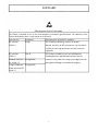
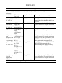
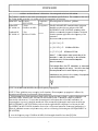
1
TRID
DENT
T POW
WER WHE
W ELCH
HAIR
R
Owneer's Opperatiion Manual
M
l
M
MODEL
# 2850-188 & 2850-220
#s
Read
d all precaautions andd instructioons in this manual before using this equiipment.
Savee this manuual for futu
ure referennce.
CONTENTS
FORWARD
-----------------------------------------------------------------------------------------------------------
6
PRODUCT
DIRECTION
----------------------------------------------------------------------------------------SPECIFICATION
-------------------------------------------------------------------------------------------------------
6
7
CAUTIONS BEFORE USE ------------------------------------------------------------------------------------------------
8
1. Driving
2. Terrain
3. Slope
4. Attendant
5. Other
UNPACKING
&
ASSEMBLY--------------------------------------------------------------------------------------
10
ADJUSTMENT----------------------------------------------------------------------------------------------------------------
14
1. Headrest height adjustment
2. Armrest Height Adjustment
3. Back angle adjustment
4. Retractable Joystick
5. Footplate height adjustment
OPERATION ---------------------------------------------------------------------------------------------------------------1. Sit On
2 Get Up
3. Clutch
4. Battery Charger and Battery Charging
5. Controller
6. Take off the battery cases
7. Wiring diagram
17
8. Flash code
9. Operation
10. Security Function:
TRANSPORTATION AND STORAGE------------------------------------------------------------------------------1. Transportation
2. Storage
MAINTENANCE --------------------------------------------------------------------------------------------------------1. Cleaning and Check-Up
2. Maintenance and Controller self-check
WARRANTY ---------------------------------------------------------------------------------------------------------------
2
28
29
31
FO
ORWAR
RD
Eleectromagnettic emissions informatioon
The Trident is intended
i
foor use in thee electromaagnetic enviironment sp
pecified bellow. The cuustomer of the
Trideent should aassure that itt is used in such
s
an enviironment.
Emisssions test
Com
mpliance
Electromagnetic envirronment - guuidance
RF emissions
Grouup 1
The Tridennt uses RF energy
e
only for its internnal
CISP
PR 11
function. Therefore,
T
itts RF emissiions are veryy low and arre
not likely to
t cause anyy interferencce in nearby electronic
equipmentt.
RF emissions
Classs B
including domestic
d
esttablishmentts and those directly
CISP
PR 11
Harm
monic emissions
The Tridennt is suitablee for use in all
a establishhments,
Not applicable
a
IEC 61000-3-2
6
Voltaage fluctuatiions / Not applicable
a
flickeer emissionss IEC
connected to the publiic low-voltaage power suupply netwoork
that suppliies buildingss used for doomestic purpposes.
6100
00-3-3
3
FORWARD
Guidance and manufacturer’s declaration - electromagnetic emissions information
The Trident Image Intensifier is intended for use in the electromagnetic environment specified below. The
customer or the user of the Trident Image Intensifier should assure that it is used in such an
environment.
IMMUNITY test IEC 60601
Compliance level
Electromagnetic environment - guidance
Test level
Electrostatic
Floors should be wood, concrete or ceramic
± 6 kV contact
± 6 kV contact
Discharge (ESD) ± 8 kV air
tile. If floors are contain synthetic
± 8 kV air
IEC 61000-4-2
material, the relative humidity should be at
least 30%.
Electrical fast
Not applicable
Mains power quality should be that of a
± 2kV for power
Transient/burst
typical commercial or hospital environment.
Supply lines
± 1kV for
IEC 61000-4-4
input/output lines
Surge
Not applicable
Mains power quality should be that of a
± 1 kV line(s) to
IEC 61000-4-5
typical
commercial or hospital environment.
line(s)
± 2kV line(s) to
earth
Voltage dips,
<5% U T
Mains power quality should be that of a
short
(>95% dip in U T)
typical commercial or hospital environment.
interruptions and for 0.5 cycle)
If the user of the (ME EQUIPMENT or ME
voltage variations
SYSTEM) requires continued operation
during power mains interruptions, it is
on power supply 40% U T
input lines
(60% dip in U T)
Not applicable
recommended that the (ME EQUIPMENT or
for 5 cycles
ME SYSTEM) be powered from an
IEC 61000-4-11
uninterruptible power supply or a battery.
70% U T
(30% dip in U T)
for 25 cycles
<5% U T
(95% dip in U T)
for 5 s
Power frequency 3 A/m
Not applicable
Power frequency magnetic fields should be at
(50/60 Hz)
levels characteristic of a typical location in a
magnetic field
typical commercial or hospital environment.
IEC 61000-4-8
NOTE U T is the a.c. mains voltage prior to application of the test level.
4
FO
ORWA
ARD
G
Guidance
annd manufactturer’s declaaration - elecctromagneticc emissions informationn
u in the electromagn
e
etic environnment specified below. The custom
mer or the user
u of
The Trident is suitable for use
T
shouuld assure th
hat it is usedd in such an electromagnnetic environment.
the Trident
IMM
MUNITY tesst IEC 606011
Compliaance Elecctromagneticc environmeent - guidancce
TEST LE
EVEL
level
Not appliccable
Radiated RF
3 V/rms
Portable and moobile RF com
mmunicationns equipmen
nt
n closer to and part of the (ME
shouuld be used no
6
IEC 61000-4-6
150 kHz to 80 MHz
EQU
UIPMENT or
o ME SYST
TEM), incluuding cabless,
thann the recomm
mended sepaaration distaance calculatted
ducted Rf
3 V/m
Cond
10 V/m
from
m the equatioon applicablle to the freqquency of thhe
IEC 61000-4-3
6
t 25 MHz
80 kHz to
transsmitter.
Recommended
d separation
n distance
d = [ 3,5 / V1 ] √P
d = [ 3,5 / E1 ] √P
80 MHz
M to 800 MHz
d = [ 7 / E1 ] √P
√
800 MH
Hz to 2.5 GHzz
wherre P is the
e maximum output
o
powerr rating of the
e
transsmitter in wa
atts (W) acccording to th
he transmitte
er
manuufacturer and d is the recoommended seeparation
distance in metress (m).
Fieldd strengths from
fr
fixed RF
R transmitterrs, as deter--mined
by an
a electroma
agnetic site survey,
s
ª should be lesss than
the compliance
c
e level in ea
ach frequency range. B
Interrference may occur in
n the vicinitty of equipment
marrked with the
e following symbol:
NOT
TE 1 At 80 M
MHz and 8000 MHz, the higher freqquency rangee applies.
NOT
TE 2 These guidelines may not appply in all situations.
s
E
Electromagn
netic propag
gation is afffected by
absorrption and reeflection froom structurees, objects annd people.
a Fiield strengthhs from fixeed transmitteers, such as base stationns for radio (cellular / cordless)
c
tellephones annd
land mobile radiios, amateurr radio, AM and FM raddio broadcasst and TV broadcast
b
can
nnot be preddicted
t electrom
magnetic envvironment du
ue to fixed RF
R transmittters, an
theorretically witth accuracy. To assess the
electrromagnetic site survey should be considered.
c
I the measuured field strrength in thhe location inn which the
If
(ME EQUIPME
ENT or ME SYSTEM) is
i used exceeeds the appplicable RF compliance
c
level abovee, the (ME
UIPMENT oor ME SYST
TEM) shoulld be observved to verifyy normal opeeration. If ab
bnormal perrformance iss
EQU
obserrved, additioonal measurres may be necessary,
n
such
s
as re-orrienting or relocating
r
th
he (ME EQU
UIPMENT or
o
ME SYSTEM).
S
b Over
O
the freqquency rangge 150 kHz to
t 80 MHz, field strenggths should be lsee than
n [V1] V/m.
5
FORWARD
FORWARD:
Thank you for choosing the Trident power wheelchair. For safety and others, please read this user's manual
carefully before operation.
(1) Please read every detail in the manual before operation and maintenance.
(2) Please carry the user's manual with you for reference and familiarity on how to operate/drive this power wheelchair.
(3) This user's manual is a part of the power wheelchair, please keep it with the chair at all times.
PRODUCT DIRECTION:
The maximum load capacity is (300 pounds) with damper and pneumatic tires to support user weight against
vibration from all terrains while driving. Be sure to read all instructions carefully before attempting to use. Being
familiar with the product operation and functionality will ensure the safety of operation for users and others.
Since the Trident power wheelchair consists of delicate electronic devices such as a joystick and controller, be
careful during transportation and storage. Be sure to keep it away from violent collision or high
humidity. Use a dry fabric to wipe up any moisture.
6
SPECIFICATIONS
SPECIFICATIONS
Trident
Seat width
49cm / 19"
Seat depth
49cm / 19"
Back height
48cm / 19"
Overall length
110cm / 43"
Overall height
116cm / 46"
Overall width
64cm / 25"
Ground clearance
5cm / 2"
Max. Speed
8km/h
Caster wheel
8"
Drive wheel
14"
Max.user weight
135 kgs / 300 lbs
Charger
24V/ 5A, off-board
Battery
12V 36Ah*2
Motor
DC 24V 320W* 32: 1*2
All specifications and designs are subject to change without notice.
7
CAU
UTION
NS BEFO
ORE US
SE
CAU
UTIONS BE
EFORE USE
E:
For th
he best perfformance annd safe operaation, read the
t followinng instructionns:
(1) Driving:
D
1. Be careful aand understaand the speeed buttons on
o the controol panel. Staart from slow
west level annd practice in
wide open spaaces.
2. Do not stepp directly onnto the footpplates when entering
e
or exiting from
m the powerr wheelchairr.
3. Make sure user's feet are on foottplates while sitting onn the power wheelchairr, and buckle up with
arm
ms on armreests.
4. Contact youur dealer im
mmediately inn case of an
ny abnormallity or operaational issuees.
5. Drive safelyy at steady speed.
s
DO NOT
N
make sharp
s
or quiick turns.
6. Be sure to ffollow the loocal traffic ruules while driving
d
outdooors.
7. Keep user's weight inclluding luggaage under liimit of (300llbs) all the time.
t
8. Each powerr wheelchaiir is for onlyy one user at
a a time. Ovverloading the
t power wheelchair
w
c
could
cause
dam
mage to thee product or battery, andd create an unsafe
u
operaational conddition.
(2) Teerrain:
1. Av
void driving in traffic.
2. Drriving on roaad instead off sidewalk/ppavement is not recomm
mended.
3. Do
o NOT drivee on grass, sand,
s
mud, gravel,
g
ice and
a other slipppery terrains.
4. DO
O NOT drivve outdoors in
i fog, rain, snowy or wet
w terrain.
(3) Slope:
S
1. Do
o NOT drivee on slope, sliding
s
or deeclining terrrains.
2. Bee sure to slow
w the speedd when comiing down ann incline or hill,
h lowest speed is reccommendedd.
3. Do
o NOT drivee on slope ovver 6 degreees at any tim
me.
4. Bee sure to keeep wheels inn vertical position againnst curbs or stairs
s
when crossing.
5. Keeep both cluutch levers inn the engageed position, parallel to the
t drive whheels, when climbing onn slopes. When
W
the
moto
or levers are in the disenngaged posittion (Fig.5-2
2), the vehiccle cannot bee operated by
b the controoller.
(Fig. 5-1 DRIVE)
(Fig. 5-2 PR
ROPEL)
8
CAU
UTION
NS BEFO
ORE US
SE
(4)Atttendant:
a. Make sure the
t user sits in the poweer wheelchaair, and havee the user's feet
f on the footplate.
f
b. Keep the motor
m
lever at engaged position (F
Fig. 5-1) to ensure brak
king when the
t power wheelchair
w
is
i
powered offf.
(5)Otther:
a. When
W
the w
wheelchair's power is in the ON possition, DO NOT
N
use a cell/mobile
c
p
phone
or anny wireless device
d
to
avoid possiible interferrence to conntroller by electro
e
feeddback. Also keep away
y from high voltage or radio
transmitter.
Bee sure to sw
witch off thee power whheelchair and ask for help in case of abnormaal movemennt resulting from
un
nexpected eleectro interfeerence.
b. Keep the poower wheelcchair away ffrom dampnness or storaage under hiigh humidityy. Wipe off moisture with
w
dry
y, clean withh soft fabricc as soon as possible.
c. Be
B sure to ppay attention
n to the warrnings, suchh as weight capacity waarning stickker on the reear of frame shown
by
y the followiing picture; keep them clean
c
on thee power wheeelchair.
9
UNP
PACKIN
NG & AS
SSEMB
BLY
PA
ARTS: (Stanndard) Contaains 1 of eachh of the follo
owing
Retractablee joystick X 1
Optional acccessories)
PARTS: (O
10
UNP
PACKIN
NG & AS
SSEMB
BLY
Warning: H
W
Have two peoople take caare of the seaat disassembbly and trannsportation. Unpack youur
pow
wer wheelchaair where it will be usedd. Be carefuul not to dam
mage anythinng during thhe unpackinng
p
process.
Plaace your pow
wer wheelchhair on a lev
vel flat surfaace. It is reco
ommended that you plaace a protective
c
covering
onn your floor..
1-1. T
Take out the left/ rightt armrests assemblies
a
f
from
carton and insert them into the
t adapterss
oon the back of seat fram
me as shown
n in the folloowing picturre. Tighten them
t
by thee knobs.
2-1. IInsert the jo
oystick bracce into the armrest
a
adaaptor and tig
ghten up wiith knob.
U
Use 3 pieces of the cable ties to fixx the joystickk cable to th
he armrest tuube.
11
UN
NPACKIING & ASSEM
A
MBLY
Warning: Have two
o people insstall the seatt assembly.
3-1. Plug inn the joystickk cable withh the controll module
whichh is located under
u
the seaat frame.
4-1. Takee the seat fraame out from
m carton. Pu
ut the seat frrame onto thhe power baase. (Fig.12--1)
4-2. Pushh the seat bacckward and make sure the
t pin locks with the
fixing brracket on booth sides. (Fig.12-2)
(F
Fig.12-2)
(Fig.12-1)
12
UNP
PACKIN
NG & ASSEMB
A
BLY
2
of 15m
mm screws tighten
t
the seat
s frame with
w power frame.
f
Optioonal “quick release” pinns may be
5-1. Use 2pcs
used for ffaster assem
mbly and disaassembly.
5mm X 2
15
6-1. Inssert the head
drest braces into the adaapters on seaat back.
13
ADJU
USTME
ENT
ADJU
USTMENT
T:
1. Heeadrest heighht adjustmen
nt:
Depress the buttoon latch; adjjust the headdrest to the proper
p
posittion.
2. Arrmrest Heighht Adjustment:
Heeight : Use Allen Key to release the
t armrest screws andd adjust arm
mrest height, maximum
m up to 1 ¾”,
¾ and
then fassten the screews.
h
Width
: Loosen the armrrest knobs annd adjust arm
mrest widthh, and then fasten
f
the knnobs. (Fig.144-1)
Flip-U
Up : For uuse's conven
nience whenn transit, the maximum fflip-up anglle is 90 degrree. (Fig.14--2)
(Fig.14-2)
(Fig.14-1)
14
ADJU
USTME
ENT
3. Baack angle adj
djustment:
Pull up
u the lever at left side of seat. Andd adjust the back to prooper position
n. (Range: 100°~125°)
TIONAL
4. Reetractable Joystick: OPT
1. Pull up the piin from bracket. (Fig.15--1)
2.Sw
wing the joyystick to thee bottom andd insert the pin
p again intto the brackket. (Fig.15-2)
(Fig.15-2)
Fig.15-1)
(F
15
ADJU
USTME
ENT
5. Footplate heigght adjustmeent:
Loosen the screw
w by Allen Keys,
K
adjustt the footplaate height acccording to user’s comffort.
16
OPE
ERATIO
ON
1. Sittting: It is im
mportant andd necessary to confirm the followinng instructio
ons for user''s safety.
(1
1)
Be surre to keep th
he power offf (power ind
dicate is off as well) beffore the userr sits down.
(2
2)
(3
3)
(4
4)
(5
5)
User may
m enter fro
om the frontt or the sides by lifting the
t arms outt of the wayy.
Have uuser's feet reest on footpllates.
Bucklee up the safeety belt; theen fasten thee belt to propper length upon
u
the user's comfort.
Switchh on the pow
wer.
Warning: Do NOT
T stand on footplates
f
w
when
sitting down or gettting up from
m the seat, which
w
will cauuse an unballanced conddition and jeopardize thee user's safeety. Be sure to switch
off the power
p
and make
m
sure th
he motor braake levers are
a in the enggaged positiion
before sitting
s
downn or getting up
u from the seat.
2. Staanding: It is important and
a necessarry to confirm
m the follow
wing instrucctions for usser's safety:
(1)Move thee power whheelchair andd user close to destinatioon.
(2)Be sure tto keep the power
p
off (ppower indiccate is off ass well) beforre the user gets
g up.
(3)User getss up by arm
mrest or otherr supporting
g method.
3. Cllutch:Wheen the pow
wer is off, tturn the cluutch to diseengaged po
osition by hand
h
to push the pow
wer
wheeelchair.
(1) Motor Driving:
D
Maake sure the power is off
ff, turn the cllutch lever to
t the engag
ged positionn, make the clutch
c
levvers headingg toward fronnt and paralllel to drive wheel, the power
p
wheeelchair can be
b
driv
ven by motoors and electtromagneticc brake workks when eng
gaged.
(2) Propelliing: Make sure
s
the pow
wer is off, turn
t
the cluttch lever too disengagedd position and
a let the llevers
vertical to the drivve wheels. Then
T
it is reaady to push the
t power wheelchair
w
b hand.
by
(DRIIVE)
(PUSH
H)
Warnning: Be surre to switch off the pow
wer before sw
witching thee clutch leveers, and keepp away from
m
others and
a childrenn. For user'ss safety, do not
n leave alone in the power
p
wheellchair
when thhe clutch levvers are in th
he disengagged position..
17
OPE
ERATIO
ON
4. Baattery Charger and Batteery Chargingg
Be
B sure to hhave the baatteries com
mpletely chaarged beforee using the power wheeelchair, esppecially forr long
distance
d
drivving. Check to see if thee power is loow accordinng to the pow
wer indicatoor on controlller.
Warrning: Do NOT
N
expose batteries too direct sunshine or closse to thermaal/heat sourcces.
Do NO
OT remove the batteriees of the pow
wer wheelchhair before unplugging.
u
Do NOT
N
switch on the pow
wer while chharging the batteries. Have the bbattery chargger
stoweed after charrging.
Follo
ow up these instructions to charge thhe battery:
(1) Take out the battery charrger; plug inn the round shape conneecter (Fig. 18-1)
1
to the socket on jooystick
(F
Fig. 18-2), hhave the cabble cord connnected to AC
A socket, annd switch onn the battery
y charger foor power
chharging.
Pow
wer cord
(Fig. 188-2)
(Fig. 18-1)
The battery
b
chargging usually
y takes 8 to 10 hours in case of usinng original battery
b
charrger, dependding on the
batterry age and ppower volum
me left in baatteries befoore charging. For best poower outputt, new batterries are
recom
mmended too be chargedd 24 hours att initial usagge.
(2) Sw
witch off thhe battery ch
harger; discoonnect plugss/connectorss from sockkets.
(3) To
T keep the batteries' working
w
life as long as possible, reegular batterry chargingg everyday is
i recommeended.
Week
kly battery ccharging is recommend
r
ded for long term periodds between use
u or storagge.
(4) Battery
B
damaage could bee dangerous. Contact your
y
dealer to
t change baatteries. Botth batteries are
a designed
d to be
chhanged sim
multaneously
y. Changing only one baattery will cause
c
a pow
wer imbalancce and conseequently jeoopardize
thhe new one.
w
use hermettically sealedd airtight leaad-acid batttery. For useer's
Warning: Power wheelchairs
conveniience, there is no need to
t add waterr or any liqu
uid; thereforre, DO
NOT oppen batteriess under any circumstannces, otherw
wise batteriess will absoluutely be
out of warranty
w
andd unable to use.
u
Makee sure of thhe battery charger
c
is thhe original. Contact yoour dealer in
i case of any
a battery questions or
o
probllems.
18
OPE
ERATIO
ON
5. Co
ontroller:
To Move Forward
M
Left
To Move
To Movve Right
Controoller Descrip
ption
On/off buutton
Maaximum
speeed / profile
inddicator
To Move
Bacckward
Speeed / profilee
deccrease buttonn
Joystick
Baattery level
inddicator
Horn butto
on
Speed / profile
p
Increase buutton
(1) Power
P
Switch: Press thhe power buttton on joysstick, both power indicaator and speeed indicatorr should be on
o
siimultaneoussly showingg battery vollume and sp
peed status. The
T power wheelchair
w
w fail to drive
will
d
if you
push the joysstick before the power indicator
i
flaashes; returnn the joystickk to the cen
nter position and then puush
it to
o drive after power indiicator flash sstops.
(2) Speed
S
Cheeck: Checkk the speeed indicatorr first: moore grades means hiigher speedd.
L
Lower
speedd is highly reecommendedd for indoorr driving.
(3) Forwarding: Control thee drive direcction by thee joystick. As
A the user'ss view, pushh joy stick away from user to
he faster.
movee forward; thhe farther th
(4) Reversing:
R
C
Control the drive
d
directioons by the jooystick. As the user's view, pull joyy stick closee to user to
movee backward;; the farther the faster. However,
H
thhe maximum
m reversing speed is a half
h to the maximum
m
fo
orwarding sppeed.
(5) Turning:
T
Conntrol the driive directionns by the jooystick. As the user's view,
v
push joy stick tow
ward right hand
h
side to
t turn rightt, and push joystick tow
ward left han
nd side to turrn left; the farther
f
the faster.
fa
(6) Electromagneetic Brake: Let
L go of jooystick back
k to center foor stop/parking by Electtromagneticc brake.
Warning: Conntrollers are all program
mmed for besst performan
nces in diffeerent circum
mstances by
maanufacturer before deliivery. Be sure
s
to conntact your dealer
d
or DRIVE
D
ME
EDICAL
techhnical centter to requeest your unnique needd by re-programming if necessarry. It is
exttremely danngerous to modify
m
or ree-program unofficially,
u
, it might caause mechaanical or
elecctronic errorrs and threatten the safetty of the useer.
C
(7) Climbing:
a. Do
o NOT drivve on any sllope over 122 degree; ottherwise, thhe wheels might
m
conseqquently get off ground even
thoug
gh there are anti-tippers on the pow
wer wheelchaair.
b. Meedium speedd drive is recommendedd for best maneuverabil
m
lity, high sppeed makes the
t power wheelchair
w
diffficult to conntrol and low
w speed willl cause the danger of motors
m
over heat
h and connsequently automatic
a
shu
ut-down by power-currrency-overlooad protectioon of controoller's self-m
monitoring system.
s
c. Do
o NOT makee U-turn or reversing
r
whhen climbinng.
(8) Descending:
D
a. Do
o NOT drivee on any slop
pe over 12 degree;
d
otheerwise it migght cause a dangerous situation.
s
b. Bee sure to keeep half-speed
ded when drriving downn hill.
c. Do
o NOT makee U-turn or reversing
r
w
when
driving
g down hill. An attendannt's help is required
r
in case
c of reveersing
when
n down a hill.
d. Bee sure to slow
w down andd drive straigght when gooing down a hill.
W
Warning: Bee sure to praactice on genntle/gradual slopes befoore driving onto
o steep asscent. Do NOT
N
ddrive over cuurbs or stairss or obstaclees over 3cm
m without cuurb climberss.
Driiving on sloppes over 12 degree is prrohibited forr safety reasson.
19
OPE
ERATIO
ON
Warning: Straap the powerr wheelchairr down firm
mly during traansportationn.
To av
void damagees to the carr or chair, bee sure to locate this prod
duct properlly.
6. Take
T
off the battery casees:
6-1. Disconnnect the joy
ystick cable & power caable from thhe control module.
m
6-2. Loosenn the Velcro holding thee battery cases.
Batteryy Case Velcrro
6-3. Disconnnect the baattery cable and control cable show
wn in .(Fig. 20-1)
2
64. Pull out tthe battery cases.
c
(Fig.220-2)
Circuit breaaker
Con
ntrol Modulee
C
Control Cablee
(Fig.220-1)
(Fig.200-2)
20
OPE
ERATIO
ON
CHA
ANGING T
THE BATTE
ERY
3-1.. Open the V
Velcro abovee the batteryy case cover..
4-1. Take off tthe case lid.. Use the crross screw driver,
d
loosens the screew of batterry connectinng
wires; theen take out the
t batteries.
21
OPE
ERATIO
ON
Reverse the steps
s
of takiing off batteries)
Insttall the batteery cases: (R
1-1. Put the neew Batteriess into the battery
b
casess. Connect the
t battery wires propeerly.
Cov
ver the case lids.
ve the case lids.
l
2-1.. Fasten the Velcro abov
22
OPE
ERATIO
ON
Reverse the steps
s
of takiing off batteries)
Insttall the batteery cases: (R
1-1.. Push the baatteries into the power base
b from reear side. (Figg.23-1)
1-2.. Connect thhe battery caables and control cable shown
s
in (Fig.23-2)
Note: Thee battery casse with circuuit breaker should
s
be installed innerr side of fraame.
C
Control
Modu
ule
Circuitt breaker
ntrol Cable
Con
(F
Fig.23-2)
(Fig.23-1))
F
the baattery cases by Velcro. Connect thee joystick caable & poweer cable to the
t control module.
m
2. Fasten
Batteery case Velccro
23
OPE
ERATIO
ON
7. Wiiring diagram
m:
Control systtem cable coonnections:
24
OPE
ERATIO
ON
8. Flaash code:
Flash
h codes indiccate the natu
ure of an abbnormal conndition directly from thee controller (fault
(
inform
mation Gaug
ge).
Without the use of any serviicing tools, the
t conditioon can be sim
mply diagno
osed.
PG / VR2 controoller:
batttery level inndicator
SYSTEM
M
co
ontrol system
m fault
HECK / ACT
TION
CH
FAULT
T
diag
gnostic guidde table
b
needss charging or
o there is a bad
b connecttion to the
The battery
Low batttery batterries. Check the
t connectiions to the batteries
b
andd the controlller
1 lightt flashing rappidly
powerr connector.. If the conn
nections are good,
g
try chharging the
voltagee
battery
y.
The left motor has
h a bad co
onnection. Ensure
E
that the motor is
Left motor
c
a secure. If
are
conneected properrly and the controller connectors
2 lightt flashing rappidly
disconneccted
probleem persists, see dealer. (Check mottor brushes)
The leeft motor haas a short circuit
c
to a battery
b
connnection. Seee dealer.
Left mootor (Checck motor bruushes)
wiring fauult
3 lightt flashing rappidly
The right
r
motor has a bad connection.
c
Ensure thatt the motor is
Right motor conneected properrly and the controller connectors
c
a secure. If
are
disconneccted probleem persists, see dealer.
4 lightt flashing rappidly
5 lightt flashing rappidly
Right mottor
wiring fauult
The riight motor has
h a short ciircuit to a baattery conneection. See
dealerr.
Inhibit acttive
The battery
b
chargger is preveenting the controller
c
froom driving the
wheellchair. Discoonnect chargger from whheelchair.
6 lightt flashing rappidly
Possiblee
A joysstick fault iss indicated. Ensure that joystick is in
i neutral beefore
joystick faault turninng ON/OFF switch on.
7 lightt flashing rappidly
A con
ntroller faullt is indicateed. Ensure that
t
all Conntroller conn
nections
are seecure. If probblem persistts, see dealeer.
8 lightt flashing rappidly
Possiblee
controlleer
fault
9 lightt flashing rappidly
Possiblee
park brakke
fault
Check the park
The park
p brakes have
h
a bad connection.
c
p brake &
motorr connectionns. Ensure thhat controlleer connectionns are securre.
If prob
blem persistts, call dealeer.
ht flashing raapidly
10 ligh
Excessivve
voltagee
This is
i usually caaused by a poor battery connection.
c
Check the
contro
oller and batttery connecctions.
Communicaation A com
mmunicationn fault is ind
dicated. Ensu
ure that handd control caable
fault
is secuurely conneccted and nott damaged.
7 lightts + S flashinng rapidly
25
OPE
ERATIO
ON
An Actuatoor Trip
8 lightts + A flashinng rapidly
Sleep Modde
Blink
Charging
Chargee step
Joystick Noot Centralizzed
Ripplee
Dynaamic shark controller:
c
Signall Status
Desccription
Insstruction
Wavy Signal
Slow Flashes
F
Flash once everyy
2.5 seccond
Conttroller lockeed up
Unnlock.
Low
w voltage
Prooceed batterry charging.
Chheck conneccters plugginng or bad
connnection, deepending onn flash frequuency.
Chheck the connnections to battery. If thhe connectioons
aree good, or trry charging. If it still hass problem,
conntact your dealer.
d
Chheck the connnections too the left haand side mo
otor. If it
stilll has probleem, contact your dealer.
1 Flashh
2 Flashh
3 Flashh
4 Flashh
5 Flashh
Sleepping
Needds Battery Charging or
o
Conn
nection probblem
Cablle connectinng problem
m on
left hand
h
side motor
m
Shorrt circuit onn left hand side
s
motoor
Cablle connectinng problem
m on
rightt hand side motor
m
Shorrt circuit onn right hand
d
side motor
6 Flashh
Malffunction
7 Flashh
Joystick Breakddown
8 Flashh
Conttroller out of order
Electtromagneticc
Brakkes Problem
m
Batteery Cable coonnecting
9 Flashh
10 Flash
Coontact your dealer.
d
Chheck the con
nnections to
o the right hand
h
modulle. If it
stilll has probleem, contact your dealer.
Coontact your dealer.
d
Peerhaps in baattery chargiing, removee the
batttery chargeer.
Maake sure thaat the joystiick is in thee center
position before switchinng on the control
sysstem.
Maake sure thaat all connecctions are seccure.
Maake sure the control syystem connections
aree secure.
Chheck the batttery connecttions.
26
OP
PERATIION
9. Op
peration
(1
1) Speed Adjustment: Push the sppeed increasse button foor speeding up; and thee decrease button
b
for slowing
s
down.
(2
2)Brake: Keeep the joystick in neutrral position,, the brake should
s
be appplied conseequently; whhen movingg, the
brake will bee applied auttomatically with a clickk sound wheen joystick is
i released.
(3
3) Forward//Backward/T
Turning: Thhe power chaair moves acccording to the directioon of joystick at
user's conntrol such as push to move forward
d, pull to moove backwar
ard, turn righ
ht to move too right side;;
turn left to
t move leftt side.
10. Security Function:
(1
1) The forw
ward/backwaard/turn speeed, accelerattion and decceleration caan be prograammable.
(2
2) Thermal overload
o
prootection.
(3
3) Current overload
o
prootection.
1. Do nott load over (300lbs)
(
to avoid
a
over loading
l
elecctric current.
2. Over 50A
5 current would causse the overlooad break.
3. Whilee over loadiing, please press the overload
o
buutton under the wheelcchair seat too reset the
overlooad breaker.
4) The fault diagnosticss of the contrroller.
(4
(5
5) The poweer-chair cann
not be moveed while chaarging the batteries.
27
TRANS
SPORTA
ATION
N & STO
ORAGE
1. Traansportationn:
Keep
p the clutch llevers at dissengaged poosition from possible sliiding damagge when trannsporting thhe power
wheeelchair. The clutch leveers should be
b parallel to
o the drive wheel and the power must
m be sw
witched off. Fix the
wheeels from movving if necessary when transportation.
T avoid anyy damage to the car or chair,
c
be surre to secure this
t productt properly.
Warning: To
orage:
2. Sto
a. Keep
K
the pow
wer wheelch
hair stored inn an area off good air cirrculation.
b. Keep
K
the pow
wer wheelchhair away frrom dampneess or high humidity
h
forr the sake off the electroonic devices.
c. Disconnect
D
thhe battery caables in casee of long terrm storage.
28
MAIN
NTENA
ANCE
1. Cleeaning and C
Check-up:
a. Cleaning: Use soft cleansers/cheemicals to cllean the pow
wer wheelchair. Do NO
OT use caustic cleanseers/
chemicals. Wipe shrouuds and tiress with clean and soft fabbrics.
b. Battery: R
Regular batttery chargiing is highhly recomm
mended to keep
k
powerr output perrformance and
saave battery hours.
h
Pleasse refer to V.10.
V
a Controlller check:
2. Maaintenance and
Main
ntenance andd Controllerr Check (rooutine, conttroller, signaal metaphorr) In case of
o malfunctiion or break
kdown
whilee in use, sw
witch off the power imm
mediately annd check ouut the probleem such as: completelyy out of pow
wer, or
the power
p
indicaator on the controller is not work
king, or looose connecteers. Contactt your dealeer immediattely in
case of
o failure too resume/reg
gain power or
o any further problem after havingg connecterss plugged inn again.
Warning: There is seelf-monitoriing installedd in the conttroller to moonitor motorr performance,
electromaggnetic brakees and the coontroller itseelf, errors will
w be indicaated by conttroller
signals.
29
MAIN
NTENA
ANCE
a. Maintenance
M
Check:
Checck Issue
Daily
Batteryy Charging
V
matic Tire Prressure (unleess flat free))
Pneum
Weeekly
Moonthly Quaarterly Annnually
V
Connecto
or cables
V
Slidin
ng Device
V
T
Tightness of screws and nuts
V
Uphoolsteries
V
Carbon Brrush of motoor
V
V
Baack to Officcial Maintennance
b. Co
ontroller Self-monitoring
g:
When
n the indicaators of the controller blinks,
b
it means
m
there aare somethiing wrong with
w the whheelchair. This
contrroller can auutomaticallyy detect thee abnormal componentts, such as Motors,
M
Maagnetic Brakkes, Batteriies,
Circu
uits and Conntroller itselff. Please advvise your deealer the frequency of thhe indicatorrs' blinks.
c. Th
he power chaair may be unable
u
to driive in case of
o a significcant error.
d. Some minor errrors allow the
t power wheelchair
w
too drive at low speed.
e. Th
he power whheelchair cann return to normal
n
usagge when erroors are repaiired or elimiinated.
f. Som
me other errrors may triigger autom
matic lock-upp protectionn, please swiitch off the controller for
fo 5 secondds and
sw
witch it on aagain.
Warning: The controller is NOT
T repairable but by techhnical speciialists. Conttact your deealer to repaair
your poweer wheelchaair controllerr.
Tire Usage:
U
1. If the
t air presssure is insuffficient, the tire
t will be damaged
d
annd may causse accident.
It is
i necessaryy to conduct regular cheecks of tire pressure
p
andd make sure it is properly filled.
(Main
ntain tire preessure at 60 psi)
2. Alw
ways checkk if the tires are crackingg, deforming
g or other obvious corro
osion.
3. To
o avoid damaages, keep the
t tires awaay from the sidewalk eddge or any obstacles
o
on
n road.
4. If you feel unnusual operaations or abnormal noisses/vibrationns, park vehhicle in a saafe place as soon as poossible,
and contact
c
yourr dealer or auuthorized shhop for repaiirs.
30
WARRANTY
There is a limited lifetime warranty on your new Trident power chair. The warranty covers the power chair for
parts only during this period. For more detail, please see the Warranty Conditions below.
Warranty Conditions:
Any work or replacement part installation must be carried out by an authorized Drive dealer / service agent.
31
To apply the warranty should your power chair require attention
please contact your service provider.
The warranty on your new Trident power chair is as follows:
a) Frame: Limited Lifetime Warranty
b) Electronics: 12 months limited warranty
c) Battery: 6 months
Note: The warranty is not transferable
Any replaced parts will be covered by this warranty for the balance of the warranty period on the power chair.
Parts replaced after the original warranty has expired will by covered by a three months warranty.
Wearable items will not generally be covered under the normal warranty period which includes but not limited
to the seat assembly or cover, tires, shroud, armrests, footplates, and lights.
The above warranty conditions apply to brand new power chairs purchased at the full retail price. If you are
unsure whether your power chair is covered, check with the service agent.
Under normal circumstances, no responsibility will be accepted where the power chair has failed as a direct
result of:
a) The power chair part not having been maintained in accordance with the manufacturer’s
recommendations.
b) Failure to use the manufacturer’s specified parts
c) The power chair or part having been damaged due to neglect, accident or improper use
d) The power chair or part having been altered from the manufacturer’s specifications or repairs having been
attempted before the service agent is notified
Please note your local service agent’s contact details in the box below. In the event of your power chair
requiring attention, contact them and give all relevant details so they can act quickly. The manufacturer
reserves the right to alter without notices any weights, measurements or other technical data shown in this
manual. All figures, measurements and capacities shown in this manual are approximate and do not constitute
specifications.
DRIVE authorized Service Agent
Name
Address
Tel
Postcode