1
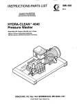
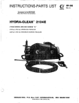
INSTRUCTIONS-PARTS LIST
This rnanulllmntains IMPORTANT
WARNINGS and INSTRUCTIONS
READ AND RETAINFOR REFERENCE
HYDRA-CLEAN8 710,720, I 01 0,1020
Pressure Washer
~~
Model 800-902, Series A 230/460 Volt, 3 Phase, 10 GPM
Model 800-904, SeriesA 230/460 Volt, 3 Phase, 20 GPM
700psi.(48bar) OPERATING PRESSURE .
1100 psi (75 bar) MAXIMUM WORKING PRESSURE
Model 800-903, Serles A 230/460 Volt, 3 Phase, 10 GPM
Model 800-905, Serles A 230/460 Volt, 3 Phase, 20 GPM
10oOpsi (69 bar) OPERATING PRESSURE
1300 p s i (91 bar) MAXlMUM WORKlNG PRESSURE
Water supply tank,gun & wand assembly,hose assembly and motor starlerare not included.
GRACO INC. RO.Box 1441 MINNEAPOLIS,MN 55440-1441
@COPYRIGHT1991, GRAGO INC.
HIGH PRESSURE SPRAY CAN CAUSE SERIOUS INJURY
FOR PROFESSIONAL USE ONLY. OBSERVE ALL WARNINGS.
Read and understand all instruction manuals beforeoperating equipment.
FLUID INJECTION HAZARD
General Safety
mis pressure washer generates very high fluid
pressure. Spray from the gun, leaks or ruptured
components can inject fluid through
your skin and into
your body and cause extremely seriousbodily injury
including the need for amputation. Also,fluid
injectedor
splashed into the eyes or on skin
the can cause serious
damage.
Pressure Relief Procedure
To reduce the risk of serious
bodily injury, includingfluid
injection and splashing in the eyesor on the skin,
always follow this procedure whenever you stop
10 minutes, when shutting down,
spraying for more than
and before checking
01 repairing any part
ofthe system.
1. Engage the trigger safety latch.
N N E R point the spray gun or wand at anyone or at any 2. Tum the sprayer off.
part of the body.NNER put hand or fingers over the
3. Disconnect the electrical supply.
spray tip.
ALWAYSfollow thePressure ReliefProcedure, before
cleaning or servicing any part of the sprayer.
N N E R try to stop or deflect leaks withyour hand or
body.
4. Shut off the water supply.
5. Disengage the trigger safety latch and trigger the
gun i o relieve pressure, and then engage the trigger
safety latch again.
Be sure equipment safety devices are operating
properly before each
use.
6. Before long-term (overnight) storage, disconnect
the water supply and disconnect the electricity.
Medical Treatment
If any fluid appears to penetrate your skin, get
EMERGENCY MEDICALTREATMENTATONCE.DO
NOT TREATAS A SIMPLE CUT. Tell thedoctor exactly
what fluid was injected.
Spray Gun Safety Devices
Be sure all gun safety devices are operating properly
before each use.Do not remove ormodify any part of
the gun; this can cause a malfunction and result in
serious bodily injury.
NOTE TO PHYSICIAN lnjectionin the skinis a
traumatic injur,! It Is Important to treat the injury
surglcaily as soon as possible. Do not delay
treatment to research toxicity Toxicity
is a
concern with some exotic coatings injected
direct& into the bloodstream. Consultationwith a
hand surgeon
plastic surgeon or reconstructive
may be advisable.
SAFETY LATCH: Whenever you stop spraying for a
moment, always set the gun Safety latch
in the engaged
or "safe"position, making the gun inoperative. Failureto
properly set the safety latch can resultin accidental
triggering of the gun.
SPRAY TIP SAFEPI: Use extreme caution when
cleaning or changing spray tips. If a spray tip clogs
while spraying, engage the gun safety latch
immediately. ALWAYS follow the Pressure Rellet
Procedure and then remove the spray tip
to clean it.
GROUNDING INSTRUCTIONS
mi s Droduct mustbe grounded. Ifit should malfunction or bieak down, grounding provides a path of least
resistance for electric current to reduce the risk of
electric shock. This equipment
is equipped witha cord
having an equipment-grounding conductor and a
grounding plug. The plug must be plugged into an
aooromiate outlet that is DroDerlv installed and
giunded in accordance with ail lbcal codes and
ordinances.
1
DANGER
improper connectionof the equipment- grounding
conductor can resultIn the risk of electrocution.
Check with a qualified electrician or service
person if you are in doubtas to whether the outlet
Is properly grounded.
GROUND FAULT CIRCUIT INTERRUPTER PROTECTION
To comply with the National Electrical Code
(NFPA 70)
and to provide additional protection from the risk
of
electric shock, connect this pressure washer
to a circuit
that is protected by a ground-fauit circuit-intempter
(GFCI).
EQUIPMENT MISUSEHAZARD
General Safety
Any misuse of the pressure washer or accessories,
such as overpressurizing, modifying parts, using
incompatible chemicals and fluids,
or using wom or
to rupture andresun in
damaged parts, can cause them
fluid injection, splashing in the eyes
or on the skin, or
other serious bodily injury, fire, explosion or property
damage.
NEVER alter or modify any part ofthis equipment;doing
so could cause it to malfunction.
CHECK ail spray equipment regularly and repair or
replace wom or damaged parts immediately.
ALWAYS wear protective eyewear and appropriate
clothing. If using a chemical injector, read andfollow
the
chemical manufacturer’s literature for
recommendations on additional protective equipment,
such as a respirator,
System Pressure
This sprayer can develophigh operating pressure. Be
sure thatall spray equipment and accessories are rated
to withstand the maximum working pressure of this
sprayer. DO NOT exceed the maximum working
pressure of any component or accessory used
in the
system.
Chemical Compatibility
BE SURE that ail chemicals used in the chemical
injector are compatible with the wetted parts of the
hose, gun, wand andtip, as givenin the Technical Data
(inside back cover). Always
read the chemical
manufacturer’s literature beforeusing any chemical in
this pressure washer.
308-533
3
..
HOSE SAFETY
High pressure fluid
in the hoses can
be very dangerous.
If the hose developsa leak, splitor rupture due to any
kind of wear, damage or misuse, the high pressure
spray emittedfrom it can causea fluid injectioninjury or
other serious bodily injury or property damage.
ALL FLUID HOSESMUST HAVE STRAlN RELIEFSON
BOTH ENDS. The strain reliefs help protect the hose
from kinks or bends at or close to the coupling, which
can resultin hose rupture.
TlGHTEN all fluid connections securely before each
use. High pressure fluid can dislodge
a loose coupling
or ailow high pressure spray to be emitted from the
coupling.
N N E R use a damaged hose. Before each use,'check
entire hosefor cuts, leaks, abrasion,bulging cwer, or
damage or movement of the hosecouplings. If any of
these conditions exist, replace the hose immediately.
DO NOT try to recouple high pressure hose or mend
it
with tape or any other device.A repaired hose cannot
contain the high pressure fluid.
HANDLEAND ROUTE HOS€S W F F U L L Y DO not pull
on hoses to move the pressure washer. Do not use
chemicals which are not compatible with the inner tube
and cover ofthe hose. DO NOT expose Graco hoseto
4
0
'
F
temperatures above 200" F (93' C) or below (-400 C).
MOVING PARTS HAZARD
Moving parts can pinch or amputate fingers or other
body parts.K€€P CLEAR of moving parts when starting
or operating the pressure washer.
Pressure Relief Procedure before checking or
servicing the pressure washer to prevent discharging
high pressure fluid from the gun.
N N E R operate the pressure washer without all guards
and interlocks installed and functioning. Follow the
TERMS
WARNING or DANGER Alerts userto avoid or correct
conditions that could causebodily injury.
NOTE
Identifies helpful procedures and information.
CAUTION: Alerts user to avoid or correct conditions
that could cause damageto the equipment.
IMPORTANT
UnitedStates Government safety standards have been adopted under the Occupational Safety and Health Act. These
standards-particularly the General Standards, Part 1910, and the Construction Standards, Part 1926-should be
consulted.
4
308-533
INSTALLATION
PUMP OIL
Check for Shipping Damage
Check the unit for any damage that may have occurred
in shipping. Notify the carrler Immediately If there Is
any damage.
Install the appropriate spray tip on the wand. See
Installing and Changing
Spray Tips. If you are using a
sandblaster kit, see its separate manual for installation
instructions.
Connect to Water Supply
Set UP.
Before connectingthe unit, be
sure theelectrical sewice
CAUTION
matches the specification in Technical Data (inside
Before attachingto the water supply, check your
back cover) and the voltage label on the unit. With the
local plumbing code regarding cross-connection
to a grounded,
unit off, connect the power supply cord
to
the water supply.
GFCI-protected circuit.
If you are using
a downstream chemical injector, install it
between the pump unloader and the high pressure
hose.
Connect the high pressure hose between the pump
outlet and the gun inlet.
CAUTION
Up to 100 ft (30 m) of high pressure hose may
beused. Longer hoses may affect sprayer
performance, and chemical injector performance,
if used.
A backflow preventer P/N 801-133 is availableto
prevent bacMlow of contaminated water into the
fresh water supply. Install it upstream from the
Pump.
Install a regulating water valve, P/N 800-258, if
inlet water pressure is Over60 psi (4.1 bar).
Do not exceed 1 6 0 "
temperature.
F (70' C) inlet water
NOTE The water source for the unit must have a
minimum 55 gallon float valve controlled
water holding tank.
308-533
5
STARTUP
Use this procedure whenever starting the pressure
washer to help insure that the unit
is ready to operate
and startingis done safely.
1. Check theoil level.
Pump: Add SA€ 20 or 30 weight non-detergentoil
as necessary.
2. lhm on the water supply.
CAUTION
Never run the unit dry. Costly damageto the
pump will result. Always be sure the water
supply is completely tumed on before
3. Trigger the gun until water sprays from the tip
indicating that the air
is purged from the system.
4.
Start the unit.
5. ALWAYS engage the gun’s trigger safety latch
to
vhenever you stop spraying, even for a moment
reduce the risk of fluid injection
or splashing in the
eyes or on the skin if theisgun
bumpedor triggered
accidentally.
6
308-533
6. ALWAYS observe the followingCAUTIONS to avoid
costly damageto the pressure washer.
CAUTION
DO NOT allow the pressure washer
to idle for
more than 10 minutes. Doingso may causethe
recirculating water to overheat and seriously
damage the pump. Tum
off the pressure washer
if it will notbe sprayingor cleaning at least every
10 minutes. If heated inlet water
is used, reduce
this timefurther.
DO NOT run the pumpdly. which will quickly
is
damage the pump.Be sure the water supply
fully tumed on before starting the pump.
DO NOT pump caustic materials; such
materials may corrode the pump components.
7. See the chemical injector or sandblaster kit manual
for detailed cleaning information
if these
accessories are used.
Trigger Safety Latch
Installing and Changing Spray Tips
WARNING
WARNING
To reduce the risk of serious bodily injury,
including fluid injection
or splashing inthe eyes
or onto the skin, use extreme caution when
changing spray tips. ALWAYS follow the
procedure below.
To reduce the risk of serious bodily injury,
includingfluid injection, splashinginthe eyes or
on the skin,ALWAYS engage the trigger safely
latch whenever spraying stops, even for a
moment.
in the engaged position, the trigger safety latch
prevents the gun from being triggered
accidentally by hand or if it is dropped or
bumped. Be sure the latch is pushed fully down
when engaging it or it cannot prevent the gun
2.
from being triggered. See Figure
1.
Follow thePressure Relief Procedure.
2. Point the gun and wand away from yourself and
anyone else.
3. Without holdingyour hand Over the spray tip(A),
pull back the quick coupler ring
(B), remove thetip
3.
and then release the ring. See Figure
4. Be sure the tip is secure before starting
to spray
again.
5. Tip holding holesare provided on the chassis
To avoid blowing theO-ring out of the quick
coupler, dueto the high pressurein the system,
never operate the pressure washer without
tip a
securely mountedin the quick coupler.
TRIGGER SAFETY LATCHSHOWN ENGAGED
TRIGGER SAFETY LATCH SHOWN DISENGAGED
Figure 2
Flgure 3
308-533
7
~
-
~~~~~
.~
~~
SHUTDOWN, FLUSHING AND STORAGE
1. Ifthe pressure washerwill be exposed to freezing
temperatures, drain all water out of the pump. If it
must be storedin freezing temperatures, flush the
unit with a 50% anti-freeze solution. Relieve
pressure. Flushthe pressure washer beforeusing it
again to remove the anti-freeze.
WARNING
PRESSURE RELIEF PROCEDURE
To reduce the risk of serious bodily injury,
including fluid injection and splashing in the
eyes, or on the skin, always follow this
procedurewhenever you stop
sprayingformore
than 10 minutes, when shutting down, and
before checking or repairing any part of the
system.
CAUTION
If water does freeze in the pressure washer,
thaw it ina warm room before trying to start
it.
DO NOT pour hot water on or into the pump;
it
1. Engage the trigger safely latch.
2. TUm the sprayer off.
3. Disconnect the electrical supply.
2. After each use, wipe all surfaces of the pressure
washer with a clean, damp cloth.
4. Shut off the water supply.
3. Perform the appropriate maintenance. See the
5. Disengage the trigger safety latch and
trigger the gun to relieve pressure, and then
engage the trigger safely latch again.
maintenance chart.
6. Before long-term (overnight) storage,
disconnect the water supply and
disconnect the electricity.
MAINTENANCE
Observing regular maintenance intervals helps ensure
that you get maximum performance andlife from the
pressure washer.
There is a break-inperiod for the pump. After changing
the oil initially, the interval between required changes
is
longer.
WARNING
To reduce the risk of serious bodily injury,
including fluid injection, splashing
in the eyes or
on the skin or injury from moving parts, always
follow the Pressure RellefProcedureWamlng
before proceeding.
.
Interval
What to do
Daily
Clean waterinlet screen and
filter. Check pumpoil level. Fill
as necessary.
Change pump break-inoil. Use
After first 50
hours of SAE
20 or 30 non-detergent oil.
operation
Each 500 hours Change pump oil. Use SAE 20 or
of operationor 30 non-detergent oil.
6 months
TROUBLESHOOTING CHART
WARNING
To reduce the risk of serious bodily injury, Includingfluid injection, splashingin the eyesor on the skin, or
injury frommoving parts, always follow the Pressure Relief Procedure Warning beforeproceeding.
ILow pressure andlor Wom or wrong size
PROBLEM
I
I
CAUSE
tip.
SOLUTION
Replace wiihtip of proper size.
Clean. Check more frequently.
Check fitter.Replace packings. See PUMP SERVICE.
pumpN n S rough Inlet filter clogged.
Worn packings, abrasives in water M
natural wear.
Inadequate water supply.
1
Check water flow rateto pump. Unit must havea
mlnimum55 gallon float valve controlled water holding
tank.
Tighten or replace.
Clean inlet and discharge valve assemblies. Check
filter.
Belt slippage.
Fouled ordirty inlet or discharge valves.
Even a small particle can
cause the valve
to stick.
Restricted inlet.
Worn inlet or discharge valves.
Leaking high pressure hose. . . .
Check garden hose, maybe collapsed or kinked.
Replace wom valves.
ReDlace hioh DreSSure hose.
Install new packings.See PUMP SERVICE.
-.
Water leakage from Wom packings.
under w m or manifold
Water in pump
Humid air condensing inside crankcase. Changeoil as specified in MAINTENANCE.
Install new packings.See PUMP SERVICE.
Worn packings.
Oil seals leakino.
Install new oil seals. See PUMP SERVICE.
Frequent or
damaged or wom plungers.
instali new plungers.~ e PUMP
e
SERVICE.
prematurefai'ure Of
in
the
fluid
being
pumped.
Abrasive
material
Install
proper
flltraiion
on
pump
inlet plumbing.
the packings
Inlet water temperaturetoo high.
exceed 1 W "
Check water temperature; may not
Overpressurizing pump.
Do not modify any faciory-set adJusimenis.
See
EQUIPMENT MISUSEHAZARD.
Excessive pressure dueto parilally plugged or replace
tip. See Installingand Changlng Spra)
or damagedtip.
Pump runningtoo longwithout spraylng.
Never run pumpmore than 10 minutes wiihout sprayin(
Do not run pump without water.
Running pump dry.
Strong surging at theForeign particlesin the inletM discharge
Clean or replace valves.See PUMP SERVICE.
inlet and low pressurevalve or wom Inlet and/or discharge valves.
on the discharge side
~
"
v-
~
~~
I
Scored.
I
IUnit
willnot start
Unit not plugged in.
Electrical sewice off/GFCi activated.
Thermal overload has tripped.
~~~~
I
Check powerwrd.
Check fuse/clrcuiI breaker. Check for proper
grounding.
Press resetb m non motor for 1 phase units. Press
stop button on the mdor siarter3for
phase unih.
308-533
9
PUMP SERVICE
To reduce the risk of serious bodily injury,
Servicing the Plungers
NOTE Plunger repair kit, P/N
803-677is available to
including fluid injection, splashing
in the eyes or replace retainers,
O-rings. washers and
on the skin, or injury from moving parts, always backup rings for three cylinders.
follow the Pressure Relief
ProcedureWarnlng
before proceeding.
1 . Loosen the plunger retaining screwtofive
six tums,
using an MlOwrench.Push theplungertowards the
NOTE The following metricwrenches are needed:
crankcase to separate the plunger and retaining
screw.
M10, M13 and M30. Repair
kits are available.
and the
Refer to the individual repair sections
2. Remove the screw fromihe plunger and examine
best
pump partspagefor more details. For the
the O-ring, backup ring and copper bearing/gasket
results, useall parts in the kits.
ifnecessary, usingkit
washer. Replace these parts,
801-474.
NOTE: There are Wo different tool kits to aid in
servicing the pump. P/N800-298 is used to
3. Remove the plunger and flinger from the plunger
ease installation of packings. P/N 800-271
shaft. Clean, examine and replace parts as
includes the items
in 800-298and tools to aid
necessary.
in the removalof packing retainers.
oil leakage from the
4. Inspect the plunger shaft for
Valves
crankcase. If leaking is obvious, replace theoil
as
seals. Otherwise,DO NOT remove these seals
NOTE: For a set of six valves, order P/N
803-664 or
they cannotbe reused. An oil seal kitis availableto
803-666.
replace the seals.
-
1. Remove the hex plug fromthe manifold
using an
M30 wrench.
2. Examine the O-ring under the hex
plug and replace
it if it is cut or distorted.
3. Remove the valve assembly from the cavity; the
assembly may come apart.
4.
NOTE: Retorque the plug after 5 hours of operation.
Pumping Section
5.
Lightly grease theoil seal, if it is being replaced,
and the flinger and replace them on the plunger
shaft. Theninstall the plunger.
6. Lightly grease the retaining screw and the outer end
oiihephger. Place the wisher,
O-ring and backup
ring around the screw and install the screw through
the plunger. Torqueto 14.4ft-lb (19.5 Nm).
7. Lubricate. the outside of each plunger. Slide the
manifold onto the crankcase, being careful to
not
damage the seals.
1. Remove the eight capscrews and lockwashers from
the manifold using an
M13 wrench.
8. Install the capscrews and washers finger-tight.
Torquethescrewsto21.7ft-lb(29Nm)followingthe
2. Carefully separate the manifold from the crankcase. tightening pattern (Figure4). Uneven tightening
may cause the manifold
to bind or jam.
NOTE: It may be necessaryto tap themanifold lightly
with asoft mallet to loosen.
I
CAUTION
Keep the manifold properly aligned with the
ceramic plungers when removing to avoid
damage to the plungeror seals.
3. Carefully examine each plunger for any scoring or
cracking and replace as necessary.
Figure 4
10
308-533
Servicing the V-Psckings
NOTE: mere are two types of packing kits: one is
packings only, the other includes the
packings, rings and retainers.
1. Remove the manifold as outlinedin the Pumping
Section.
2. Carefully pull the packing retainer from the
manifold. Examine the O-ring and
replace it if it is
cut or damaged.
3. Remove the v-packing andhead ring. Pullout the
intermediate retainer ring. Remove the second
v-packing and second head ring.
4.
inspect all parts and replace as necessary.
5. moroughly cleanthe packing cavities and examine
for debris and damage.
6. Lightly grease the packing cavities and then
replace the packings in the
following order: head
ring, v-packing, intermediate ' ring, head ring,
v-packing and packing retainer with the O-ring
installed in the retainer groove.
CAUTION
install the parts in the proper order and facing
the correct direction. Improperlyinstalled parts
will cause a malfunction.
7. Reassemble the manifold
as instructed in Servicing
the Plungers.
308-533 11
PARTS DRAWING
800-902 Hydra-Clean@710 Pressure Washer
800-903 Hydra-Clean@I010 Pressure Washer
For wiring diagrams, see pages 13 and
15
9’
12
308-533
7
PARTS LIST
800-902 Hydra-Clean@710 Pressure Washer
800-903 Hydra-Clean@1010 Pressure Washer
REF
NO.
1
2
PART
DESCRIPTION
NO.
803-566 BELT GUARD
801 -940 SCREW. CaD. hex hd.
3
4
5
6
7
8
9
10
11
12
13
14
100-21 4 WASHER, Lock, 5/16
100-527 WASHER, Flat, 5/16
800-447 CHASSIS
177-144 LABEL, Warning. belt guard 1
800-444 BRACKET, Rail Stiffener 1
803-mSCREW, Cap, hexhd, 3/8-16x5
802-845 FOOT, Rubber 4
801-020 NUT. Lock 1/2-13
172-981 LABEL, Waming,~chassis
176-250 LABEL, Warning, chassis
803-560 BRACKET, Rail Stiffener
801 -376 HUB. Motor. 5 hD
Afor 800-902 only) 1
803-576 H B, Motor, 7-1/2 hp
(for 800-903 only)
803-769 SHEAVE, Motor
(for 800-902 only)
801-91 1 SHEAVE, Motor
(for 800-903 only)
803-575 HUB, Pump
(for 800-902 only)
803-574 HUB, Pump
Afor 800-903 only)
803-770 S EAVE, Pump
(for 800-902 only)
803-088 SHEAVE, Pump
(for 800-903 only)
803-517 LABEL, Keep From Freezing 1
100-214 WASHER, Lock, 5/16
15
16
17
18
19
r
100-1 33 W SHER,
800-902
Lock, 3y8)
(for 800-903 only) 4
QTY
1
REF
NO.
20
5
5
1
21
2
22
2
1
1
1
~
1
1
1
1
1
23
24
25
26
27
28
29
30
31
32
33
34
35
1
1
4
36
37
38
39
40
41
PART
DESCRIPTION
NO.
100-527 WASHER, Flat, 5/16
(for 800-902 only)
100-023 WASHER, Flat, 3/8
QTY
4
803-579 MI TOR,
Y 800-903
5hp,TEF
Only ,
3 phase (for 800-902 only)
803-580 MOTOR, 7-1/2 hp, TEFC,
3 phase (for 800-903 only)
801-941 SCREW, Cap, hex hd
(for 800-902 only)
803-593 S C R W , Cap, hex hd
(for 800-903 only)
100-023 WASHER, Flat, 3/8
100-133 WASHER, Lock, 318
803-761 BELT, Drive (for 800-902 only
803-762 BELT, Drive (for 800-903 on14
802-784 WASHER, Lock, 1/2
803-591 WASHER, Flat, 112
803-396 DECAL, WamingKaution
800-445 BRACKET, Pump Support
803-577 PUMP, 10 GPM(see page 16)
802-084 NIPPLE, 3/4x2
801 -787 TEE, 314
803-791 PLUG, Plastic, 3/4
803-599 PLUG, Plastic, 1/2
800-687 UNLOADER, 700 PSI
(for 800-902 only)
800-688 UNLOADER, lo00 PSI
(for 800-903 only
159-239 NIPPLE, Hex 3/8x12
803-141
803-142 NIPPLE,B rex
=
112 NPSM x 318 NPT
801 -274 BUSHING, Hex, 3/8x1/4
803-872 LABEL, Graco G
802-096 BUSHING, Hex, 1/2x3/4
4
1
1
4
4
2
2
2
2
2
2
1
2
1
1
1
1
1
1
1
1
1
1
1
1
1
5 hp Wlrlng Diagram
230 Volt, 3 Phase
308-533
13
PARTS DRAWING
800-904 Hydra-Clean@720 Pressure Washer
800-905 Hydra-Clean@1020 Pressure Washer
13 and 15
For wiring diagrams, see pages
I
I
I
I
I
14
308-533
\
40
PARTS LIST
800-904 Hydra-Cleans 720 Pressure Washer
800-905 Hydra-Clean@1020 Pressure Washer
REF
NO.
1
2
3
4
5
6
7
8
9
10
11
12
13
14
15
16
17
18
19
PART
QTY
DESCRIPTION
NO.
1
803-566 BELT GUARD
801-940 SCREW, Cap, hexhd,
5
5/16-18X3/4
5
100-21 4WASHER, Lock, 5/16
5
100-527 WASHER, Flat, 5/16
1
800-447 CHASSIS
1
177-144 LABEL, Warning, belt guard
1
8w-444 BRACKET, Rail Stiffener
803-777 SCREW, Cap, hex hd, 3/8-16X5 2
4
802-845 FOOT. Rubber
2
801-020 NUT, Lock 1/2-13
'1
172-981 LABEL. Wamina.chassis
1
176-250 LABEL; Warnin& chassis
1
803-560 BRACKET. Rail Stiffener
603-767 HUB, Motor, 10hp
1
(for 800-904 only)
801 -623 HUB, Motor, 15hp
1
(for 800-905 only)
803-878 SHEAVE, Motor
1
(for 800-904 only)
803-879 SHEAVE, Motor
1
(for 800-905 only)
803-575 HUB, Pump
1
(for 800-904 only)
803-574 HUB, Pump
1
(for 800-905 only)
603-880 SHEAVE, Pump
1
(for 800-904 only)
803-776 SHEAVE. Pumo
1
(for 606-905 only)
803-517 LABEL, Keep From Freezing 1
100-133 WASHER, Lock, 3/8
4
(lor 800-004 on1 )
802-784 WASHER, Lock, 1&
6
(for 800-905 only)
REF
NO.
20
21
22
23
24
25
26
27
28
29
30
31
32
33
34
35
36
37
38
39
40
PART
NO.
DESCRIPTION
QTY
100-023 WASHER, Flat, 3/8
(for 800-904 only)
4
803-591 WASHER, Flat, 1/2
4
800-905 Only)
803-581 M TOR, 10 hp, TEFC,
3 phase (for 800-904 only) 1
803-582 MOTOR, 15 hp, TEFC,
3 phase(for 800-905 only)
1
803-593 SCREW, Cap, hexhd
(for 800-904 only)
4
803-592 SCREW, Cap, hex hd
(for 800-905 only)
4
100-023 WASHER, Flat, 3/8
2
100-133 WASHER, Lock, 3/8
2
803-677 BELT, Drive
2
802-784 WASHER, Lock, 1/2
2
803-591 WASHER, Flat, 1/2
2
803-396 DECAL, Warning/Caution
1
800-446 BRACKET, Pump Support
2
803-578 PUMP, 20 GPM (see page18)
1
803-585 NIPPLE, Hex, 1
1
1
803-586 TEE, 1
803-791 PLUG, Plastic, 1
1
803-599 PLUG, Plastic, 1/2
1
800-687 UNLOADER, 700 PSI
(for 800-904 only)
1
800-688 UNLOADER, loo0 PSI
1
(lor 800-905 only)
168-595 ADAPTER, Hex 3/4X1/2
1
1
21 4-956 HOSE, Bypass
202-965 SWIVEL, 1x3/4
1
1
157-191 NIPPLE, Hex, 1/2x3/4
1
803-872 LABEL, GracoG
S,,
7.5, 10 & 15 hp
Wring Diagram
230 Volt, 3 Phase
308-533
15
PARTS DRAWING
803-577 Pump Assembly, 10 GPM
16
308-533
REF
NO.
1
2
8
9
10
11
12
13
14
15
16
17
18
19
20
21
22
23
24
25
26
27
28
29
30
PART
DESCRIPTION
NO.
803-657 SCREW, Cap, socket hd.
803-639 WASHER, Lock 16
KIT 62 VALVE ASSEMBLY
803-630 O-RING
803-61 6 COVER, Valve
803-655 SCREW, Cap, sockethd.
SEAL, Oil
KTT 37
803-606 CRANKCASE
801-475 DIPSTICK
803-615 GASKET, Cover
KIT 74
SCREW, Piston
KIT74
O-RING
RING, Backup
KIT 74
KIT74
WASHER, Flat
803-609 PISTON
803-607 CRANKSHAFT
803-612 COVER, Crankcase
803-608 ROD, Connecting 3
801-652 WASHER, Lock
803-294 SCREW, Cap, socket hd.
802-344 O-RING
802-345 GAUGE, Sight
801-484 PLUG, Hex hd.
803-651 SCREW, Cap, socket hd. 9
803-645 PIN, Wrist
Repair Kit Ref
Part No. No.
803-660
Seal
Description
37 SEAL.
I I
Oil
QTY
8
6
6
2
8
3
REF
NO.
31
33
34
35
36
37
38
1
1
1 42
3
3
39
41
1
1
48
3
3
3
6
6
1
1
2
43
44
45
46
47
49
50
51
52
53
54
55
PART
NO.
DESCRIPTION
803-610 GUIDE, Piston
803-641 WASHER, Flinger
803-653 SCREW, Cap, hex hd.
803-605 COVER, Crankcase
803-613 SPACER
KIT 32
SEAL, Oil
803-632 O-RING
803-638 BEARING, Ball
803-633 BUSHING
802-317 WASHER, Lock 4
802-305 SCREW, Cap, socket hd. 4
803-647 PLUG, Hex hd. 1
803-643 WASHER, Flat
803-289 WASHER, Flat 1
803-61 1 HEAD, Pump
KIT 39 O-RING
KIT 39 RETAINER, Packing
KIT 38,39 PACKING 6
KIT 39 RING, Head
KIT 39 RING, Intermediate
803-635 KCI
802-357 RING, Retaining 1
803-614 SPACER
am
3
3
a
2
1
1
2
2
3
1
1
6
6
6
3
1
1
3
W.
Incl.
2
Oil Seal
Packina
Packing &
Retainer
RETAINER,
Packing
PACKING
RING. Head
Valve
Plunger O-RING
Repair
SCREW, Piston
RING, Back-up
308-533 17
PARTS DRAWING
803-578 Pump Assembly, 20 GPM
///-
18
308-533
22
27
PARTS LIST
803-578 Pump Assembly, 20 GPM
REF
NO.
1
2
8
9
10
11
12
13
14
15
16
17
18
19
20
21
22
23
24
25
26
27
28
29
PART
NO.
QTY
DESCRIPTION
803-659 SCREW, Cap, socket hd.
803-640 WASHER, Lock
KIT43 ' VALVE ASSEMBLY
803-631 O-RING
803-650 CAI? Valve
803-624 COVER, Crankcase
SEAL, Oil
KIT 44
803-617 CRANKCASE
803-648 DIPSTICK
803-627 GASKET, Cover
KIT 74 SCREW, Piston
KIT 74 O-RING
RING, Backup
KIT 74
KIT 74 WASHER, Flat
803-621 PISTON
803-618 CRANKSHAFT
803-625 COVER, Crankcase
803-620 ROD, Connecting
803-639 WASHER, Lock
803-656 SCREW, Cap, socket hd.
802-344 O-RING
802-345 GAUGE, Sight
801-484 PLUG, Hex hd.
803-652 SCREW, Cap, socket hd.
Repair KR
Part No.
803-660
Oil Seal
803-664
Valve
803-665
Oil Seal
803-667
Plunger
Repair
803-668
Packing
803-669
Packing &
Retainer
8
12
6
6
6
1
3
1
'1
1
3
REF
NO.
30
31
32
33
34
35
36
37
38
40
41
42
43
3
3
3
3
1
44
45
46
47
48
49
1
3
6
6
2
1
2
10
50
51
52
53
54
PART
NO. DESCRIPTION
803-646 PIN, Wrist
803-629 GUIDE, Piston
KIT 79,80 RING, Backup
803-641 WASHER, Flinger
803-654 SCREW, Cap, hex hd.
803-623 COVER, Crankcase
803-628 SHIM
802-353 O-RING
803-637 BEARING, Tapered Roller
803-634 BUSHING
803-658 SCREW, Cap, socket hd.
803-649 PLUG, Hex hd.
803-647 PLUG, Hex hd.
803-644 WASHER, Flat
803-643 WASHER, Flat
803-622 HEAD, Pump
O-RING
KIT 80
KIT 80 RETAINER, Packing
KIT 79,80 PACKING
RING, Head
KIT 80
RING, Intermediate
KIT 80
803-636 KEY
802-357 RING, Snap
KIT 32
SEAL, Oil
QTY
3
3
3
3
8
1
2
2
2
3
4
1
1
1
1
1
3
3
6
6
3
1
1
1
Ret
No.
54
8
12
16
17
18
19
32
49
32
47
48
49
50
51
RING, Back-up
WASHER. Flat
RING, Back-up
PACKING
RING, Back-up
O-RING
RETAINER,
Packing
PACKING
RING. Head
RING,
Intermediate
~
1; 1
I: I
I1 I
I
I
308-533
19
ACCESSORIES
(Must be purchased separately)
DOWNSTREAM CHEMICAL INJECTOR KIT BACKFLOW PREVENTOR 801-133
Prevent back-up of contaminated water into fresh
800-117 BRASS UP TO5.5 GPM (21 LPM)
supply. Install upstream of pump.
800-425 BRASS 5.6 TO 10.8 GPM (21 TO 41
INLET PRESSURE REGULATOR 800-258
Regulates inlet water pressure to 60 psi (4 bar)
maximum.
HOSE ASSEMBLY WITH QUICK COUPLERS
800-375
3/8” diameterx 50foot x 4OOO psi (276 bar) permanently
Includes 803-350 spray gun, 3 2 spray wand, quick
coupler for hose connection
and adjustable nozzle.
800-042
Includes 800-222 stainless steel spray gun, 3 2
stainless steel spraywand and stainless steel threaded
connections for hose and spray tip.
coupled hose with801-568 and 801-569 3/8” quick
couplers.
TECHNICAL DATA
Model 800-902
Motor (Totally Enclosed
:an Cooled)
IlectricalService 230
5.0 hp, 3 phase
v011/20
3 phaseor
amp/ 230
Model 800-903
Model 800-904
7.5 hp. 3 phase 10.0 hp,
volV20 amp/
3 phase or
3 phase
Model 800-905
15.0 hp.
230 volt/30 amp/
3 phaseM
3 phase
230 voItl40 amp/
3 phaseor
Acrylonitrile and Buna-Nwver and tube
Bypass Hose
Synthetic yam and EPDM
Pressure Washer
(including fittings)
Anodized aluminum, Aluminumor Bronze alloys, Brass, Copper, Nylon-PTFE composite.
Ceramic. Bunaon Phenolic, 303,304, and 316 Stainless Steel, P
de-12
or without Yellow Chromate Plate
Thermoplastic. PTFE Carbon Steel, Zinc with
PTFE is a registered trademarkof the DuPont Companfl