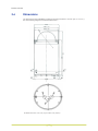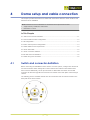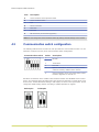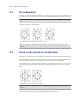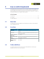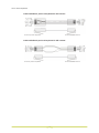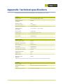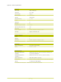
1
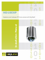
HD18EXP
Installation Manual
Explosion-proof analogue PTZ dome camera with Day/Night
Note: To ensure proper operation, please read this manual thoroughly before using the
product and retain the information for future reference.
Copyright © 2013 Siqura B.V.
All rights reserved.
HD18EXP
Installation Manual v1 (131311-1)
AIT55
Nothing from this publication may be copied, translated, reproduced, and/or published by
means of printing, photocopying, or by any other means without the prior written permission
of Siqura.
Siqura reserves the right to modify specifications stated in this manual.
Brand names
Any brand names mentioned in this manual are registered trademarks of their respective
owners.
Liability
Siqura accepts no liability for claims from third parties arising from improper use other than
that stated in this manual.
Although considerable care has been taken to ensure a correct and suitably comprehensive
description of all relevant product components, this manual may nonetheless contain errors
and inaccuracies. We invite you to offer your suggestions and comments by email via
[email protected]. Your feedback will help us to further improve our documentation.
How to contact us
If you have any comments or queries concerning any aspect related to the product, do not
hesitate to contact:
Siqura B.V.
Zuidelijk Halfrond 4
2801 DD Gouda
The Netherlands
General : +31 182 592 333
Fax : +31 182 592 123
E-mail : [email protected]
WWW : www.siqura.com
2
Contents
1
2
About this manual .....................................................................................
4
Safety and compliance ..............................................................................
5
2.1
2.2
2.3
3
4
Safety requirements ............................................................................
Cautions .............................................................................................
Regulations .........................................................................................
5
5
7
Product overview ......................................................................................
8
3.1
3.2
Features .............................................................................................
Models ...............................................................................................
8
8
3.3
3.4
3.5
3.6
Operation requirements ........................................................................
Package contents .................................................................................
HD18EXP mounting accessories .............................................................
Dimensions .........................................................................................
9
9
9
10
Dome setup and cable connection .............................................................
11
4.1
4.2
4.3
4.4
4.5
4.6
4.7
4.8
4.9
5
Switch and connector definition .............................................................
Communication switch configuration ......................................................
ID configuration ..................................................................................
Dome control protocol configuration .......................................................
Cable definition and requirements ..........................................................
22-Pin data cable .................................................................................
22-Pin connector definition ...................................................................
RS-485 connector definition ..................................................................
Cable wiring and connection ..................................................................
Use a control keyboard .............................................................................
5.1
5.2
5.3
11
12
13
13
14
15
15
16
16
18
Baud rate ...........................................................................................
Functions ............................................................................................
Cable definitions ..................................................................................
18
18
18
Appendix: Technical specifications ............................................................
20
3
1
About this manual
What this manual covers
This manual describes how to install and connect the HD18EXP, Siqura's explosion-proof,
analogue PTZ dome camera with Day/Night. Instructions for configuration and operation of
the HD18EXP can be found in the User Manual.
Who should read this manual
This manual is intended for technicians involved in the installation of HD18EXP cameras.
What you should already know
To be able to install and connect the HD18EXP properly, you should have adequate knowledge
and skills in the following fields.
●
CCTV systems and components
●
Electrical wiring and low-voltage electrical connections
●
Video, audio, data, and contact closure transmissions
●
Hazardous environments and ATEX regulations
Before you start the installation
We advise you to read and observe all instructions and warnings in this manual before you
proceed. Retain this manual with the original bill of sale for future reference and warranty
service. When you unpack your product, check for missing or damaged items. If any item is
missing, or if damage is evident, do not install or operate this product. Contact your supplier
for assistance.
Important: The printed manual referenced by DEX-MAN-11-138-A and the printed checklist
referenced by DEX-MAN-10-119-A are the governing documents for installation of the
HD18EXP. These must be followed to the letter by the installer. For additional installation
information, see also the printed Supplementary Installation Information document.
Why specifications may change
At Siqura, we are committed to delivering high-quality products and services. The information
given in this manual was current when published. As we are relentlessly working to improve
our products and user experience, all specifications are subject to change without notice.
We like to hear from you!
Customer satisfaction is our first priority. We welcome and value your opinion about our
products and services. Should you detect errors or inaccuracies in this manual, we would be
grateful if you would inform us. We invite you to offer your suggestions and comments via
[email protected]. Your feedback helps us to further improve our documentation.
4
2
Safety and compliance
This chapter contains safety instructions telling you what to do and what not to do when you
work with the HD18EXP. It also offers information on product compliance with environmental
regulations and explains how to dispose of the product at the end of its service life.
In This Chapter
2.1 Safety requirements................................................................................................5
2.2 Cautions................................................................................................................5
2.3 Regulations............................................................................................................7
2.1
Safety requirements
General
The safety information contained in this section, and on other pages of this manual, must be
observed whenever this unit is operated, serviced, or repaired. Failure to comply with any
precaution, warning, or instruction noted in the manual is in violation of the standards of
design, manufacture, and intended use of the module. Siqura assumes no liability for the
customer's failure to comply with any of these safety requirements.
Trained personnel
Installation, adjustment, maintenance, and repair of this equipment should conform to all
local codes and should be performed by trained and qualified personnel with adequate
expertise in hazardous area practice and ATEX requirements. For correct and safe use of the
equipment and in order to keep the equipment in a safe condition, it is essential that both
operating and servicing personnel follow standard safety procedures in addition to the safety
precautions and warnings specified in this manual, and that this unit be installed in locations
accessible to trained service personnel only.
2.2
Cautions
Reduce the risk of electric shock
To reduce the risk of electric shock, do not perform any servicing other than contained in the
operating instructions unless you are qualified to do so.
Reduce the risk of ignition of hazardous atmospheres
To reduce the risk of ignition of hazardous atmospheres, disconnect the equipment from the
supply circuit before opening. Keep assembly tightly closed when operating. Conduit runs
must have a sealing fitting connected within 2 inches of the enclosure.
Warning: TO REDUCE THE RISK OF IGNITION DO NOT OPEN WHEN AN EXPLOSIVE GAS
ATMOSPHERE MAY BE PRESENT.
5
Safety and compliance
Handle the camera carefully
Do not abuse the camera. Avoid striking, shaking, etc., as the camera can be damaged by
improper handling or storage.
Install electrical wiring carefully
Ask a qualified electrician to perform the wiring for the installation. For power specifications,
see Appendix: Technical specifications of the Installation Manual. Ground the camera
appropriately to prevent electric shock or damage. Do not block any ventilation openings.
Install in accordance with the manufacturer’s instructions.
Do not disassemble the camera
To prevent electric shock, do not remove screws or covers. There are no user-serviceable
parts inside. Consult technical support if a camera is suspected of malfunctioning.
Do not operate the camera beyond the specified temperature,
humidity, and power source ratings
Use the camera under conditions where the temperature, humidity, and power source do not
exceed the values and ranges given in Appendix: Technical specifications of the Installation
Manual.
Never face the camera towards the sun
Do not aim the camera at bright objects. Whether the camera is in use or not, never aim it at
the sun or other extremely bright objects, as this can damage the camera.
Do not use strong or abrasive detergents
Use a damp cloth to clean the camera when it is dirty. If the dirt is hard to remove, use a mild
detergent and wipe gently. To clean the lens, use lens tissue or a cotton tipped applicator and
ethanol. Do not clean the lens with strong detergents.
6
Safety and compliance
2.3
Regulations
This device complies with Part 15 of the FCC Rules.
Operation is subject to the following conditions.
●
This device may not cause harmful interference.
●
This device must accept any interference received, including
interference that may cause undesired operation.
This symbol on the product or on its packaging indicates that this
product shall not be treated as household waste in accordance with
Directive 2002/96/EC. Instead it shall be handed over to the
applicable collection point for the recycling of electrical and
electronic equipment. By proper waste handling of this product you
ensure that it has no negative consequences for the environment
and human health, which could otherwise be caused if this product is
thrown into the garbage bin. The recycling of materials will help to
conserve natural resources.
For more information on how to recycle this product, please contact
your local city office, your household waste disposal service or the
seller of the product.
Compliance is evidenced by written declaration from our suppliers,
assuring that any potential trace contamination levels of restricted
substances are below the maximum level set by EU Directive
2002/95/EC, or are exempted due to their application.
7
3
Product overview
The HD18EXP is a high-speed, explosion-proof, analogue PTZ dome camera which delivers
superb performance and durability in extremely harsh and hazardous environments, while
reducing the risk of explosion from, for example, electrical and dust ignition. This chapter
introduces the HD18EXP and its features.
In This Chapter
3.1 Features................................................................................................................ 8
3.2 Models.................................................................................................................. 8
3.3 Operation requirements........................................................................................... 9
3.4 Package contents....................................................................................................9
3.5 HD18EXP mounting accessories................................................................................ 9
3.6 Dimensions.......................................................................................................... 10
3.1
Features
Siqura HD18EXP PTZ Dome
3.2
●
1/4" CCD (Super HAD 2 CCD)
●
36x Optical zoom
●
12x Digital zoom
●
Preset speed up to 400°/sec
●
Preset position / Sequence / Autopan / Cruise
●
Multiple PTZ protocols supported
●
Digital slow shutter
●
Day/Night with IR-cut filter
●
Auto white balance
●
Wide dynamic range
●
Backlight compensation
●
16 Masking zones
●
4 Alarm inputs, 1 alarm output
●
Stainless steel housing
●
IP67 Ingress Protection
●
ATEX Approved for gas and dust
Models
The HD18EXP series includes models with NTSC ( /N) and PAL support ( /P).
8
Product overview
3.3
Operation requirements
A minimum of one control device is required for operation, such as a control keyboard, a DVR,
or a PC. The HD18EXP contains a built-in receiver that decodes commands originating from a
control device.
The built-in Pelco D protocol provides connectivity to other surveillance systems and allows
the HD18EXP to be integrated with the surveillance systems of other suppliers.
For more information, see Appendix: Technical specifications ( on page 20).
3.4
Package contents
Before you proceed, verify that the box contains the items listed here. If any item is missing
or has defects, do not install or operate the product. Contact your supplier for assistance.
3.5
Explosion-proof housing with dome
body inside
30 cm cable harness for power supply, video, and
RS-485
CD containing Installation Manual and
User Manual
Printed documentation:
- DEX-MAN-11-138-A
- DEX-MAN-10-119
- Supplementary Installation Information
- EC Declaration of Conformation
HD18EXP mounting accessories
The following products are available to mount the HD18EXP camera.
WMEX-01
Wall Mount, Stainless steel, Explosion-proof PTZ
CMEX-01
Ceiling (Pendant) Mount, Stainless steel, Explosion-proof PTZ
PMEX-01
Pole Mount, Stainless steel, Explosion-proof PTZ
9
Product overview
3.6
Dimensions
The dimensions of the HD18EXP including its housing are Ø195 x 373 mm (Ø7.7 x 14.7 in.).
See the following diagrams for detailed dimensions.
HD18EXP dimensions: side view (top) and base view (bottom)
10
4
Dome setup and cable connection
This chapter provides illustrations and tables with information about the switch locations and
definitions of the HD18EXP.
Note: Mechanical camera installation is described in these printed documents:
●
Supplementary Installation Information
●
DEX-MAN-11-138-A
In This Chapter
4.1 Switch and connector definition...............................................................................11
4.2 Communication switch configuration........................................................................ 12
4.3 ID configuration....................................................................................................13
4.4 Dome control protocol configuration........................................................................ 13
4.5 Cable definition and requirements........................................................................... 14
4.6 22-Pin data cable.................................................................................................. 15
4.7 22-Pin connector definition.....................................................................................15
4.8 RS-485 connector definition................................................................................... 16
4.9 Cable wiring and connection................................................................................... 16
4.1
Switch and connector definition
Before connecting the HD18EXP to other devices of a CCTV system, configure the camera ID
and communication switch settings first. These switches are located on the bottom of the
dome camera. Additionally, the 22-pin Connector for Data Cable connection and the ISP
Connector for firmware upgrade kit connection are located on the back plate of the analogue
camera.
The following picture and table describe the various switches and connectors located on the
back plate of the dome camera.
11
Dome setup and cable connection
Item
Description
A
Communication control protocol switch
B
Communication switch
C
N/A
D
22-Pin connector
E
ID Switch
F
Reserved
G
ISP Connector (for firmware upgrades)
Note: Do not change the Communication switch (B) factory-default settings of the camera.
4.2
Communication switch configuration
The following table shows the function of each pin within the Communication switch. You are
advised to verify the accuracy of the communication switch configuration.
Communication switch
Switch
1
Description
RS-485
2
3
Termination
4
Line lock
5
System initialisation. Switch 5 is mainly used to
restore the factory defaults of the camera.
6
Camera upgrade. Users must reset switch 6 after
firmware upgrades are carried out.
RS-485 is the interface which enables communication between the HD18EXP and its control
device. This means that the RS-485 setup of the camera and that of the control device must
be the same. The RS-485 default setting is half-duplex, as shown in the figure below. Do not
change the default setting without consulting a qualified specialist or supplier.
Half duplex
Full duplex
RS-485 settings
12
Dome setup and cable connection
4.3
ID configuration
If there is more than one camera installed on the same site, it is necessary to define the ID of
the camera. Use the dial switches to set the ID of the HD18EXP before you install the camera.
Important: No two cameras should be given the same ID or a communication conflict may
occur.
If, for example, the ID of your HD18EXP is 123, the arrow of each dial should point to the
respective number, as shown below.
Switch settings for a HD18EXP for which the ID is 123.
Note: The number "0" should be located straight up (as shown above) for correct switch
definition.
4.4
Dome control protocol configuration
Depending on the devices in your surveillance system, you need to define the protocol you are
going to use so that the devices can communicate with one another. Generally, just one
protocol should be used even if the devices on the network are from different manufacturers.
Use the dial switch to define the control protocol and baud rate of your HD18EXP.
For example, if you are using the Pelco D protocol, with a switch number of 01, then the baud
rate is 2400, and you must set the dials on the control protocol switch to 0 and 1, as shown
below.
An example of the control protocol set to Pelco D
Note: The number "0" should be located straight up (as shown above) for correct switch
definition.
Refer to the table below to select the appropriate protocol and baud rate.
13
Dome setup and cable connection
4.5
Switch #
Protocol
Baud Rate
00
VCL
9600
01
Pelco D
2400
02
Pelco P
4800
04
Chiper
9600
05
Phillips
9600
07
DSCP
9600
08
AD422
4800
09
DM P
9600
11
Pelco D
4800
12
Pelco D
9600
13
Pelco P
2400
14
Pelco P
9600
15
JVC
9600
21
Kalatel-485
9600
22
Kalatel-422
4800
Cable definition and requirements
For operation, the HD18EXP camera requires a video and cable harness which includes the
following cables.
●
Video
The video cable sends video signals to a remote viewing site. Using a coaxial BNC cable to
send the video signals is recommended.
●
Power
The power cable provides a 24 Vac power supply to the HD18EXP module.
●
RS-485 data
The RS-485 cable carries commands from a control device to the camera. A Cat 5 / 24
AWG cable is recommended.
●
Alarm
For connecting to alarm devices, such as sensors, sirens, or flashing lights.
Note: Make sure that the power supply corresponds with the power requirement of the
camera, or product impairment may ensue. If any mistake occurs, contact a qualified
maintenance engineer.
14
Dome setup and cable connection
4.6
22-Pin data cable
The cable harness of the HD18EXP includes the following cables.
AC 24 V data cable
Important: Do not use undue strain when pulling the cables during installation. Make sure
that the ground wire is inserted into the mid-pin of the terminal block when wiring the power
cable and only fasten the cables once they are connected to the camera.
4.7
22-Pin connector definition
With the 22-pin connector, installers can simply connect the power, video, and RS-485 cables
to the HD18EXP camera. See the table and figure below for the definition of each pin.
The alarm input and output devices, such as alarm sensors, sirens, or flashing lights, can be
easily connected to the alarm pins as necessary. For more information on connecting alarms,
see Cable wiring and connection ( on page 16).
Pin
Definition
Pin
Definition
1
AC 24-1/DC (+)
12
ALM-1
2
ALM NC
13
ALM-2
3
AC 24-2/DC (–)
14
ALM-3
4
ALM NO
15
ALM-4
5
FG
16
ALM-5
6
ALM COM
17
ALM-6
7
T+
18
ALM-7
8
R-
19
ALM-8
9
T-
20
ALM GND
10
R+
21
VGND
11
ISOG
22
Video
15
Dome setup and cable connection
4.8
RS-485 connector definition
RS-485 is the interface that allows the HD18EXP camera to communicate with its control
device. The recommended cables for the RS-485 communication are Cat 5 cables. The
maximum cable length for 24 AWG wire is 4000 feet (1219 metres). If the total cable length
exceeds 4000 feet, use a repeater to maintain the signals.
The camera and control keyboard are connected with a terminal block. See the figure and
table below for pin definition and wiring.
RS-485 connector
4.9
Pin
Corresponding pin(s) on the 22-pin connector
Definition
1
7, 10
T+, R+, (D+)
2-4
Reserved
5
8, 9
T-, R-, (D-)
Cable wiring and connection
Users may need to do cable wiring in the following instances.
●
Connecting self-provided cords to the connector housing instead of using the equipped
data cable
●
Connecting alarm input and output devices
See 22-Pin connector definition ( on page 15) for the exact position of each cord.
To wire a connection
1
Insert the terminal pin into the pin holes on the connector housing.
2
Connect the 22-pin connector to its mating port on the HD18EXP camera.
Make sure that the hook is facing outwards, as shown in the figure.
16
Dome setup and cable connection
Inserting a terminal into the connector
To unlock the terminal
●
Press the hook with an appropriate tool and pull it out gently.
Removing a terminal from the connector
17
5
Use a control keyboard
The HD18EXP camera can be integrated into the surveillance systems of other suppliers using
one of the many built-in protocols. For an overview of which protocols are available for use
with the HD18EXP, see the section entitled Dome control protocol configuration ( on page 13).
This chapter describes how to integrate a Pelco keyboard.
In This Chapter
5.1 Baud rate.............................................................................................................18
5.2 Functions............................................................................................................. 18
5.3 Cable definitions................................................................................................... 18
5.1
Baud rate
The default baud rate of the HD18EXP is set to 9600.Make sure that your control keyboard
uses a compatible baud rate.
5.2
5.3
Functions
Function
Instruction
Set Preset
Number key + press and hold the <Preset> button for three
seconds
Go Preset
Number key + <Preset> to command a dome camera to go to a
specific preset position
Display or hide an
OSD menu
7 7 <Preset>
Move cursor in OSD
menu
Move the cursor up/down/right/left by pushing the joystick up/
down/right/left, respectively
<ENTER>
7 7 <Preset>
Reset the dome
camera
7 8 <Preset>
Cable definitions
The following diagrams provide an overview of the cable definitions for connecting the
HD18EXP camera with a Pelco control keyboard.
18
Use a control keyboard
Cable definition P protocol keyboard to PTZ camera
For the P protocol keyboard
For the HD18EXP camera
Cable definition D protocol keyboard to PTZ camera
For the D protocol keyboard
For the HD18EXP camera
19
Appendix: Technical specifications
This appendix gives the technical specifications of the HD18EXP series cameras.
Camera
Image sensor
1/4” CCD (Super HAD 2 CCD)
Image resolution horizontal
650 TVL
Effective pixels
570 k
Electronic shutter
1~1/10000 s
Signal-to-noise ratio
>50dB (AGC off)
Minimum scene
illumination
0.1 lux colour, 0.01 lux (b/w)
Video output
1 Vpp, 75Ω
Angle of view
55.8° wide to 1.55° tele
Focal length
3.4 - 122.4 mm
Focus mode
Auto/manual
Image control
Wide dynamic range
On/off
Backlight compensation
On/off
White balance
Auto/manual
Iris control
Auto/manual
Automatic gain control
Auto/manual
Day/night (IR-cut filter)
On/off
Digital slow shutter
On/off
Digital zoom
12x
Optical zoom*
36x
Electronic image
stabiliser
On/off
*Maximum zoom operation can give optical distortion because of exd polycarbonate bubble.
Functions
Privacy masks
16
Directional on-screen
display
Compass direction, azimuth, elevation
PTZ coordinate data
Via Pelco D (set/get)
20
Appendix: Technical specifications
Pan/Tilt
Pan travel
360° continuous
Tilt travel
10°~190°
Preset speed
400°/s
Manual speed
0.5°~90°/s
Presets
256 presets
Preset accuracy
+/- 0.1°
Cruise
8
Sequence
8
Auto pan
4
Proportional pan and tilt
On/off
Resume after power loss
Yes
Zone title
16
Home function
Preset, sequence, auto pan, cruise
Auto flip
Digital, mechanical, off
Contact closures
Inputs
8
Outputs
1
Reactions
Preset, sequence, auto pan, cruise
Powering
Power consumption
20 W (45 W with heater)
Power
24 Vac +/- 20%
Environmental
Operating temperature
(camera)
Continuous -45 °C to +50 °C (-49 °F to +122 °F); 60
°C (140 °F) maximum
Certified temperature
(camera)*
Continuous -20 °C to +40 °C (-4 °F to +104 °F)
Ingress protection
IP66, IP67 (IP68 on request)
Certification*
ATEX, II 2 G/D, Exd IIB T5 T100 °C zone 1/21 and 2/22
Entries
1x M20 and 2x M25 (EExd)
*Certifications are site-specific. Consult factory with detailed requirements.
21
Appendix: Technical specifications
Mechanical
Dimensions
Ø195 x 373 mm (Ø7.7 x 14.7 in)
Weight
14 kg (30.9 lbs)
Housing
Stainless steel 316
Bubble
3 mm polycarbonate
Bubble coating
Factory-applied for up to 3 years maintenance-free
operation.
22