1
C
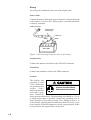
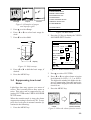
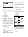
Yo u r L o c a l A g e n t / D e a l e r
9-52, Ashihara-cho,
Nishinomiya, Japan
Te l e p h o n e :
Te l e f a x :
0 7 9 8 - 6 5 - 2 111
0798-65-4200
All rights reserved.
Printed in Japan
PUB. No. OME-43861
(DAMI)
GP-1610CF
FIRST
EDITION
G
:
:
MAR. 1997
MAR. 7, 2001
SAFETY INSTRUCTIONS
Safety Instructions for the Operator
WARNING
CAUTION
Do not open the equipment.
Use the proper fuse.
Hazardous voltage which can
cause electrical shock, burn or
serious injury exists inside the
equipment. Only qualified
personnel should work inside
the equipment.
Use of a wrong fuse can result in fire or
permanent equipment damage.
Do not disassemble or modify the
equipment.
Fire, electrical shock or serious injury
can result.
Turn off the power immediately if water
leaks into the equipment or the equipment is emitting smoke or fire.
Continued use of the equipment can cause
fire or electrical shock.
GPS position and velocity accuracies
are controlled by the U.S. Department
of Defense. Position may be degraded
up to 100 meters.
Do not use the equipment for other than
its intended purpose.
Personal injury can result if the equipment
is used as a chair or stepping stool, for
example.
Do not place objects on the top of the
equipment.
The equipment can overheat or personal
injury can result if the object falls.
Do not place liquid-filled containers on
the top of the equipment.
Fire or electrical shock can result if a
liquid spills into the equipment.
Do not operate the equipment with wet
hands.
Electrical shock can result.
Keep heater away from equipment.
Heat can alter equipment shape and melt
the power cord, which can cause fire or
electrical shock.
About the TFT LCD
The TFT LCD is constructed using the
latest LCD techniques, and displays
99.99% of its pixels. The remaining 0.01%
of the pixels may drop out or blink, however this is not an indication of malfunction.
Safety Instructions for the Installer
WARNING
Do not work inside the
equipment unless totally
familiar with electrical
circuits.
Hazardous voltage which can
shock, burn or cause serious
injury exists inside the equipment.
Turn off the power at the
mains switchboard before
beginning the installation.
Post a sign near the switch
to indicate it should not be
turned on while the equipment is being installed.
Fire, electrical shock or
serious injury can result if the
power is left on or is applied
while the equipment is being
installed.
CAUTION
Ground the equipment to
prevent electrical shock
and mutual interference.
Confirm that the power supply voltage
is compatible with the voltage rating
of the equipment.
Connection to the wrong power supply
can cause fire or equipment damage. The
voltage rating appears on the label at the
rear of the display unit.
Use the correct fuse.
Use of a wrong fuse can cause fire or
equipment damage.
Keep the following compass safe
distance.
Standard Steering
Display Unit
0.7 m
0.6 m
TABLE OF CONTENTS BY SUBJECT
FOREWORD
A Word to GP-1610CF Owners .................iv
Features....................................................... v
System Configuration ................................ vi
INSTALLATION
1.1
1.2
1.3
1.4
1.5
1.6
Equipment Lists............................. 1-1
Installation of Standard
Equipment ..................................... 1-3
Installation of Transducers .......... 1-10
Installation of Optional
Sensors ........................................ 1-19
Connection of Optional
Equipment ................................... 1-21
Initial Settings ............................. 1-24
OPERATIONAL OVERVIEW
2.1
2.2
2.3
2.4
2.5
2.6
2.7
Control Description ....................... 2-1
Inserting Chart Cards .................... 2-2
Turning On/Off the Power ............. 2-2
Adjusting Tone and Brilliance ....... 2-3
Plotter Displays ............................. 2-3
Sounder Displays ........................... 2-5
Basic Menu Operation ................... 2-7
VIDEO SOUNDER OPERATION
3.1
3.2
3.3
3.4
3.5
3.6
3.7
3.8
3.9
3.10
3.11
3.12
3.13
Principle of Operation ................... 3-1
Automatic Sounder Operation ....... 3-2
Manual Sounder Operation ........... 3-2
Suppressing Low Level Noise ....... 3-3
Selecting Picture Advance
Speed ............................................. 3-4
Suppressing Interference ............... 3-4
Erasing Weak Echoes .................... 3-4
Changing Zoom Magnification
Factor ............................................. 3-5
Selecting Hue
(color arrangement) ....................... 3-5
Measuring Depth ........................... 3-5
Knowing Depth Change by
Audible Chime .............................. 3-5
Selecting Unit of Depth
Measurement ................................. 3-6
Offsetting the Depth Readout ........ 3-6
3.14 Displaying the Water Temperature
Graph ............................................. 3-6
3.15 Selecting Unit of Water
Temperature Measurement ............ 3-7
3.16 Offsetting Water Temperature
Readout .......................................... 3-7
3.17 Fish Alarm ..................................... 3-7
3.18 Bottom Alarm ................................ 3-8
3.19 Water Temperature Alarm ............. 3-8
3.20 Turning On/Off the Expansion
Range Marker ................................ 3-8
3.21 Receiver Sensitivity (gain)
Adjustment .................................... 3-9
3.22 Selecting Bottom-Lock
Expansion Width ........................... 3-9
3.23 Stopping Transmission .................. 3-9
3.24 Interpreting the Display ............... 3-10
GPS, CHART OVERVIEW
4.1
4.2
4.3
4.4
4.5
4.6
4.7
4.8
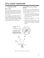
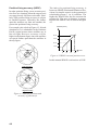
Principle of GPS ............................ 4-1
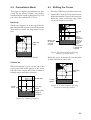
Presentation Mode ......................... 4-3
Shifting the Cursor ........................ 4-3
Selecting Screen Center by
Cursor ............................................ 4-4
Shifting the Display ....................... 4-4
Centering Position ......................... 4-4
Changing Chart Scale/Range ........ 4-4
Chart Cards .................................... 4-4
TRACK
5.1
5.2
5.3
5.4
5.5
Stopping/Restarting Plotting of
Track .............................................. 5-1
Changing Track Color ................... 5-1
Erasing All Track ........................... 5-1
Changing Track Plotting
Interval .......................................... 5-2
Smoothing Track ........................... 5-2
MARKS
6.1
6.2
6.3
6.4
6.5
6.6
6.7
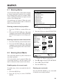
Entering Marks .............................. 6-1
Entering Event Marks .................... 6-1
Erasing Individual Marks .............. 6-2
Changing Mark Attributes ............. 6-2
Entering the MOB Mark ............... 6-3
Erasing All Marks.......................... 6-3
Radar Target Mark......................... 6-4
i
WAYPOINTS, ROUTES
7.1
7.2
7.3
7.4
7.5
7.6
7.7
Entering Waypoints .......................
Erasing Individual Waypoints .......
Changing Waypoint Position .........
Changing Waypoint Mark Size .....
Entering Routes .............................
Editing Routes ...............................
Erasing Routes...............................
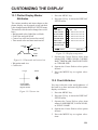
CUSTOMIZING THE DISPLAY
7-1
7-3
7-3
7-4
7-4
7-5
7-5
SETTING DESTINATION
8.1
8.2
8.3
Setting Destination ........................ 8-1
Skipping Route Waypoints ............ 8-3
Cancelling Destination .................. 8-3
PLOTTER-RELATED ALARMS
9.1
9.2
9.3
9.4
Arrival/Anchor Watch Alarm ........
XTE (Cross Track Error) Alarm ....
Speed Alarm ..................................
Trip Alarm .....................................
9-1
9-2
9-2
9-2
POSITION-RELATED
OPERATIONS
10.1
10.2
10.3
10.4
Displaying Position in LOPs ....... 10-1
Offsetting GPS Position .............. 10-1
Selecting Navaid ......................... 10-2
Displaying True or Magnetic
Bearings ....................................... 10-2
10.5 Magnetic Variation ...................... 10-2
10.6 Offsetting Chart Position ............. 10-3
GPS OPERATIONS
11.1 GPS Setup Menu ..........................11-1
11.2 Speed Averaging ...........................11-2
OPTIONAL EQUIPMENT
SETUP
12.1 Selecting Sensors......................... 12-1
12.2 Selecting Autopilot, Remote
Display ........................................ 12-1
12.3 Setting up DGPS Beacon
Receiver ....................................... 12-1
ii
13.1 Plotter Display Marker
Attributes .....................................
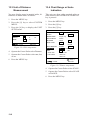
13.2 Chart Attributes ...........................
13.3 Unit of Distance Measurement ....
13.4 Chart Range or Scale Indication..
13-1
13-1
13-2
13-2
MAINTENANCE &
TROUBLESHOOTING
14.1
14.2
14.3
14.4
14.5
14.6
14.7
14.8
Maintenance ................................
Replacement of Fuse, Battery .....
Simple Troubleshooting ..............
Error Messages ............................
Diagnostic Tests ..........................
GPS Monitor Display ..................
Demonstration Display ................
Memory Card Operations
(for technicians)...........................
14.9 Clearing the Memory ..................
14-1
14-1
14-2
14-3
14-4
14-5
14-6
14-6
14-7
APPENDIX
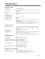
Specifications..........................................A-1
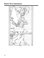
World Time Standards ............................A-2
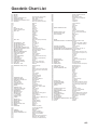
Geodetic Chart List .................................A-3
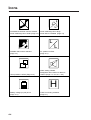
Icons .......................................................A-4
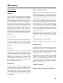
Glossary ..................................................A-5
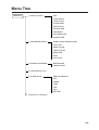
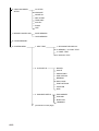
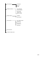
Menu Tree ...............................................A-9
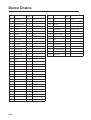
Decca Chains ........................................A-12
Packing List ..........................................A-13
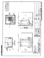
DRAWINGS
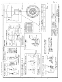
Antenna Unit...........................................D-1
Display Unit ............................................D-2
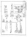
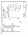
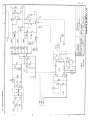
SCHEMATIC DIAGRAMS
GPS Plotter Interconnection Diagram .... S-1
GPS Plotter Schematic Diagram............. S-2
GPS Plotter Schematic Diagram............. S-3
INDEX
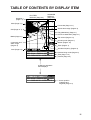
TABLE OF CONTENTS BY DISPLAY ITEM
Waypoint
(Page 7-1)
SOUNDER
DISPLAY
(Page 2-5)
PLOTTER
DISPLAY (Page 2-3)
0
01
Chart (Page 4-4)
Course bar (Page 13-1)
50
Grid (Page 13-1)
100
Marks (Page 6-1)
Flag (destination) (Page 8-1)
Course to destination (Page 8-1)
Fish school (Page 3-10)
150
Cross-track error
alarm range
(Page 9-2)
Own ship mark (Page 5-1)
Bottom (Page 3-10)
50k
Icons (Page A-4)
Arrival alarm range (Page 9-2)
L
200
H
CSE 350.0° SPD 16.8kt
2D
DEP 110 m TMP 1 6 . 0 °C 13:42
POS 34°26.345’N 135°41.232’E
L
Track (Page 5-1)
Sounder frequency (Page 2-5)
Position-fixing mode (Page 2-2)
Time (Page 11-2)
Position (Page 4-2)
CURS key alternates
these displays.
BRG+ 232.0° RNG+ 0.00nm 2D
DEP 110 m TMP 1 6 . 0 °C 13:42
+
34°43.801’N 135°21.163’E
Cursor position
in latitude and
longitude (Page 4-3)
iii
FOREWORD
A Word to GP-1610CF Owners
Congratulations on your choice of the FURUNO GP-1610CF
COLOR GPS PLOTTER SOUNDER. We are confident you will
see why the FURUNO name has become synonymous with quality and reliability.
For over 40 years FURUNO Electric Company has enjoyed an
enviable reputation for innovative and dependable marine electronics equipment. This dedication to excellence is furthered by
our extensive global network of agents and dealers.
This equipment is designed and constructed to meet the rigorous
demands of the marine environment. However, no machine can
perform its intended function unless installed, operated and maintained properly. Please carefully read and follow the recommended
procedures for installation, operation and maintenance.
We would appreciate hearing from you, the end-user, about whether
we are achieving our purposes.
Thank you for considering and purchasing FURUNO equipment.
iv
Features
The GP-1610CF is a totally integrated GPS receiver, color video
plotter and color video sounder. It mainly consists of a display unit
and a GPS antenna.
Navigation information is displayed on a bright 5.6-inch color TFT
LCD. On-screen information shown are position, range and bearing to cursor position, range, bearing, ETA and TTG to waypoint,
etc.
A high sensitivity receiver tracks up to eight satellites simultaneously. An 8-state Kalman filter ensures optimum accuracy in
determination of vessel position, course and speed.
The main features of the GP-1610CF are
• Comprehensive navigation data displays.
• Bright 5.6-inch color LCD with temperature compensated tone
and brilliance control.
• Automatic coastline chart loading.
• Position display in latitude and longitude, Loran C LOPs or
Decca LOPs.
• Outputs steering information to FURUNO autopilots (FAP-50/
55/300/330).
• Improved position accuracy with connection of DGPS beacon
receiver (option).
• FURUNO and NAVIONICS chart cards.
• Memory capacity: 2,000 points of track, 100 marks, 100 event
marks, 200 waypoints and 20 routes.
• Alarms: Arrival, Anchor Watch, Cross-track Error, Depth, Fish,
Speed, Trip, and Water Temperature.
• Man overboard feature records latitude and longitude coordinates at time of man overboard and provides continuous updates of range and bearing to that point.
• "Highway" display provides graphic presentation of ship's track
and is useful for monitoring cross track error.
• Automatic or manual video sounder operation.
v
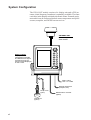
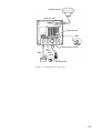
System Configuration
The GP-1610CF mainly consists of a display unit and a GPS antenna. A dual frequency transducer is optionally available. The chart
card drive in the display unit loads electronic charts. External equipment which can be connected include water temperature and speed
sensors, autopilot, and DGPS beacon receiver.
ANTENNA UNIT
Receives signal from
GPS satellite.
DISPLAY UNIT
Ship’s position is
calculated in longitude
and latitude from signal
received from the antenna unit and displayed
on the screen.
Ship’s mains
10.2—31.2 VDC
External equipment
(Autopilot, etc.)
Temp. sensor
(option)
Transducer
(option)
vi
DGPS beacon receiver
(option)
INSTALLATION
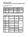
1.1 Equipment Lists
Standard supply
No.
Name
Type
Code No.
Qty
1
Display Unit
GP-1610CF-E
1
2
Antenna Unit
GPA-016
1
3
Installation
Materials
CP86-00300
000-041-038
1 set
4
Spare Parts
SP86-00300
004-394-640
1 set
Remarks
Optional equipment
No.
1
Name
Type
Code No.
Remarks
CP20-01700
004-372-110
30 m, for
antenna cable
extension
CP20-01710
004-372-120
50 m, for
antenna cable
extension
Antenna
cable set
2
Right-angle
antenna base
No.13-QA330
000-803-239
3
L-angle
antenna base
No.13-QA310
000-803-240
4
Antenna base
for rail
mounting
No.13-RC5160
000-806-114
5
Mast mount
fixture
CP20-01111
000-040-722
ST-02MSB
000-137-986
6
ST sensor
ST-02PSB
000-137-987
T-02MTB
000-040-026
With 8 m cable,
transom mount
T-03MSB
000-040-027
With 8 m cable,
thru-hull type
7
Temperature
sensor
For mounting
antenna unit
Thru-hull type
1-1
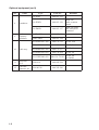
Optional equipment (con't)
No.
Name
Type
520-5PSD
8
9
10
1-2
Code No.
000-015-125
520-5PWD
000-015-126
With 8 m
cable, transom
mount
520-5MSD
000-015-127
With 8 m cable
and waterproof
connector
524ST-MSD
000-015-224
520ST-PWD
000-015-128
MJ-A6SPF0011-100
000-132-336
6P-4P, 10m
MJ-A6SPF0011-050
000-132-244
6P-4P, 5m
MJ-A6SPF0012-100
000-133-817
6P-6P, 10m
MJ-A6SPF0012-050
000-134-424
6P-6P, 5m
MJ-A7SPF0003-050
000-136-730-01
7P-6P, 5m
for DGPS
Transducer
Dual
frequency
transducer
Cable assy.
Remarks
11
Inner hull
kit S
22S0191-0
000-802-598
12
Converter
connector set
CP86-00310
004-395-280
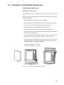
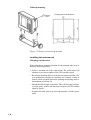
1.2 Installation of Standard Equipment
Installing the display unit
Mounting considerations
The display unit can be installed on a tabletop or on the overhead.
When selecting a mounting location for the display unit keep the
following in mind:
• Keep the display unit out of direct sunlight.
• The temperature and humidity should be moderate and stable.
• Locate the unit away from exhaust pipes and vents.
• The mounting location should be well ventilated.
• Mount the unit where shock and vibration are minimal.
• Keep the unit away electromagnetic field generating equipment
such as motor, generator.
• For maintenance and checking purposes, leave sufficient space
at the sides and rear of the unit and leave slack in cables.
• A gyrocompass will be affected if placed too close to the display unit. Observe the following compass safe distances to prevent disturbance to the gyrocompass:
Standard compass: 0.7 meters
Steering compass: 0.6 meters
Cover
Tabletop
Overhead
Figure 1-1 Display unit mounting methods
1-3
Tabletop mounting
Dummy
cover
Cutting size for flushmount
Figure 1-2 Display unit mounting methods
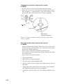
Installing the antenna unit
Mounting considerations
When selecting a mounting location for the antenna unit, keep in
mind the following points:
• Select a location out of the radar beam. The radar beam will
obstruct or prevent reception of the GPS satellite signal.
• Be sure the location offers a clean line-of-sight to satellite. Objects within line-of-sight to a satellite, for example, a mast or
funnel, block reception and cause prolonged acquiring time or
interruption of position fix.
• Mount the unit as high as possible. This will keep the unit free
of water spray, which can interrupt reception of GPS satellite
signal if frozen.
• Separate the unit well away from the antenna of radio equipment.
1-4
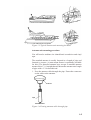
Figure 1-3 Typical antenna unit mounting locations
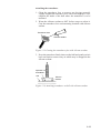
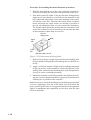
Antenna unit mounting procedure
You will need a medium size slotted-head screwdriver and vinyl
tape.
The standard antenna is usually fastened to a length of pipe and
fastened to a mast. (A mast mount fixture is optionally available
for this.) The threaded antenna base accepts a standard antenna
mount with a 1"-14 straight thread. Mount the antenna on a length
of pipe with a 1"-14 threaded end.
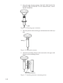
1. Pass the antenna cable through the pipe. Fasten the connector
on the cable to the antenna.
Antenna
Pipe
Antenna cable
Figure 1-4 Passing antenna cable through pipe
1-5
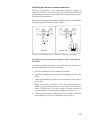
2. Screw the pipe into the antenna. DO NOT USE TOOLS TO
FASTEN THE ANTENNA TO ITS MOUNTING; ONLY
HAND TIGHTEN.
Pipe
Figure 1-5 Fastening pipe to antenna
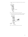
3. Tape the junction between the pipe and antenna unit with vinyl
tape.
Taping
Figure 1-6 Taping the antenna
4. Attach the mounting fixture to the mast and set the pipe with
antenna to the mounting fixture.
Mast
Mounting
fixture (note direction)
Figure 1-7 Attaching antenna to mounting fixture
1-6
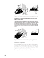
5. Tape the antenna unit, mounting fixture and mast with vinyl
tape.
Vinyl tape
Figure 1-8 Securing antenna to mast with vinyl tape
6. Attach a clamp to the antenna unit and tighten. Leaving some
slack in the antenna cable as shown, fix it with vinyl tape.
Slotted-head
screwdriver
Clamp
Leave slack
in cable.
Vinyl tape
Figure 1-9 Fixing the antenna cable with vinyl tape
1-7
Wiring
All wiring are terminated at the rear of the display unit.
Power cable
Connect the power cable to the power connector. Connect the leads
to the battery (12 or 24 VDC); white to plus(+) terminal and black
to minus(-) terminal.
Cable connector
Power cable
w/fuse (3A)
Lead wire
Black
White
BATTERY
Figure 1-10 Connecting the power cable to the battery
Antenna unit
Connect the antenna unit cable to the GPS ANT connector.
Transducer
Connect the transducer cable to the XDR connector.
Ground
The display unit
contains several
CPUs. While they
Ground the equipment to
are operating, they
prevent electrical shock
radiate
noise,
and mutual interference.
which can interfere
with radio equipment. Ground the
unit to prevent interference. The grounding wire should be 1.25 sq
or larger and as short as possible. Connect the grounding wire to
ship's ground by silver-alloy brazing. On a fiberglass boat, it is
best to install a ground plate that measures about 20 cm by 30 cm
on the outside of the hull bottom to provide a ground point. If this
is not practical, the engine block can be used.
CAUTION
1-8
ANTENNA UNIT
DISPLAY UNIT
Earth terminal
Earth
DPGS beacon receiver
Black
Ext.
equip.
White
Shield
TRANSDUCER
Figure 1-11 Display unit, rear view
1-9
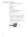
1.3 Installation of Transducers
Installing the inside-hull mount transducer
Necessary tools
You will need the following tools:
• Sandpaper (#100)
• Silicone sealant
• Silicone grease
Remarks on installation
• Do the installation with the boat hauled out of the water.
• Turn off the engine while installing the equipment.
• Install the transducer in the engine room.
Selecting the mounting location
Keep the following points in mind when selecting a mounting location:
• The mounting location should be where the hull is of singlehull thickness and is void of air or flotation materials other than
solid fiberglass between the transducer face and the water.
• Do not place the transducer over hull struts or ribes which run
under the hull.
• Avoid a location where the rising angle of the hull exceeds 15°,
to minimize the effect of the boat’s rolling.
• You will finalize the mounting location through some trial and
error. The procedure for this is shown later.
Center line
50cm
50cm
1/2
1/3
15cm
15cm
Mounting location
for transducer
Figure 1-12 Inside-hull transducer mounting location
1-10
Attaching the transducer
1. Clean the transducer face to remove any foreign material.
Lightly roughen the transducer face with #100 sandpaper. Also,
roughen the inside of the hull where the transducer is to be
mounted.
2. Warm the silicone sealant to 40°C before usage to soften it.
Coat the transducer face and mounting location with silicone
sealant.
Transducer face
Silicone sealant
Figure 1-13 Coating the transducer face with silicone sealant
3. Press the transducer firmly down on the hull and gently twist it
back and forth to remove any air which may be trapped in the
silicone sealant.
Squeeze out
air bubbles.
Hull
Silicone
sealant
Figure 1-14 Attaching transducer to hull with silicone sealant
1-11
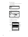
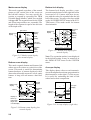
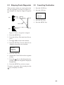
Observing the picture
1. Press the POWER key to turn on the display unit.
2. Press the PLTR key.
3. Press the AUTO key.
AUTO MODE
Cruise
Fish
Manual
Figure 1-15 Auto mode selection screen
4. Press ▼ twice to select Manual.
AUTO MODE
Cruise
Fish
Manual
Low
High
Gain
Range
5
10
40
80
160
Shift
0m
20
300m
Figure 1-16 Auto mode adjustment screen
5. Confirm that Gain is set at 5 (midpoint).
6. Press ▼ once to select Range.
7. Press t four times to select 10.
8. Note the depth to the seabed.
Reddish
brown
Zero
line
2
Color bar
Reddish
brown
4
Bottom
Red
6
Depth
scale
8
Depth
3.9
CSE 180.0°
DEP
3.9 m
SPD 16.8kt
TMP 16.0 °C
POS 34° 26.245' N
09:00
135° 41.232' E
Figure 1-17 Video sounder picture
1-12
10
2D
If the bottom is displayed in red and the light-blue color appears
the mounting location is suitable. You can leave the transducer
in position.
If the bottom is not displayed in reddish brown, the mounting
location is unsuitable. Relocate the transducer and do the
following.
1. Press the POWER key to turn off the power.
2. Gently dismount the transducer with piece of wood.
3. Do steps 1 through 5 in the previous procedure. Repeat until
a suitable location is found.
Final preparation
Support the transducer with a piece of wood to keep it in place
wile it is drying. Let the transducer dry 24–72 hours.
1-13
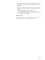
Installing the thru-hull mount transducer
Transducer mounting location
This type of mounting provides the best performance of all, since
the transducer protrudes from the hull and the effect of air bubbles
and turbulence neat the hull skin is reduced. When the boat has a
keel, the transducer should be at least 30 cm away from it. Typical
through hull mountings are shown in the figure on the next page.
The performance of the video sounder is directly related to the
mounting location of the transducer, especially for high-speed cruising. The installation should be planned in advance, keeping the
standard cable length (8 m) and the following factors in mind:
• Air bubbles and turbulence caused by movement of the boat
seriously degrade the sounding capability of the transducer. The
transducer should, therefore, be located in a position where water flow is the smoothest. Noise from the propellers also adversely affects performance and the transducer should not be
mounted nearby. The lifting strakes are notorious for creating
acoustic noise, and these must be avoided by keeping the transducer inboard of them.
• The transducer must always remain submerged, even when the
boat is rolling, pitching or up on a plane at high speed.
• A practical choice would be somewhere between 1/3 and 1/2 of
the boat's length from the stern. For planing hulls, a practical
location is generally rather far astern, so that the transducer is
always in water regardless of the planing attitude.
Transducer outline drawings
22
24
120
120
30
All dimensions 28
in millimeters
Ship's
bow
68
68
520-5PSD (option)
87
520-5MSD (option)
Figure 1-18 Transducer outline drawings
1-14
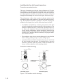
Acceptable transducer mounting locations
Deep-V hull
• Position 1/2 to 1/3 length of the hull from stern
• 15 to 30 cm off center line (inside first lifting strakes).
Figure 1-19 Transducer mounting location on deep-V hull
High speed V-planing hull
• Within the wetted bottom area
• Deadrise angle within 15°
Figure 1-20 Transducer mounting location on high speed
V-planing hull
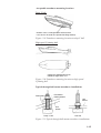
Typical through-hull mount transducer installations
Fairing block
Flat washer
Rubber washer
Hull
bottom
Hull
bottom
Deep-V Hull
Flat Hull
Figure 1-21 Typical through-hull mount transducer installations
1-15
Procedure for installing the thru-hull mount transducer
1. With the boat hauled out of the water, mark the location selected for mounting the transducer on the bottom of the hull.
2. If the hull is not level within 15° in any direction, fairing blocks
made out of teak should be used between the transducer and
hull, both inside and outside, to keep the transducer face parallel with the water line. Fabricate the fairing block as shown
below and make the entire surface as smooth as possible to
provide an undisturbed flow of water around the transducer.
The fairing block should be smaller than the transducer itself
to provide a channel to divert turbulent water around the sides
of the transducer rather than over its face.
Hole for
stuffing tube
Upper
half
BOW
Lower
half
Saw along slope of hull.
Figure 1-22 Construction of fairing block
3. Drill a hole just large enough to pass the threaded stuffing tube
of the transducer through the hull, making sure it is drilled vertically.
4. Apply a sufficient amount of high quality caulking compound
to the top surface of the transducer, around the threads of the
stuffing tube and inside the mounting hole (and fairing blocks
if used) to ensure watertight mounting.
5. Mount the transducer and fairing blocks and tighten the locking nuts. Be sure that the transducer is properly oriented and its
working face is parallel to the waterline.
Note: Do not over-stress the stuffing tube and locking nuts through
excessive tightening, since the wood block will swell when the
boat is placed in the water. It is suggested that the nut be tightened
lightly at installation and retightened several days after the boat
has been launched.
1-16
Installing the transom mount transducer
This type of mounting is very commonly employed, usually on
relatively small I/O or outboard boats. Do not use this method on
an inboard motor boat because turbulence is created by the propeller ahead of the transducer.
There are two methods of installation: flush with hull (for flat hulls)
and projecting from hull (for deep V-hulls).
D
D>50 cm
Flat Hull
Deep V-hull
Figure 1-23 Transom mount transducer mounting locations
Installing the transom mount transducer flush with hull (for
flat hulls)
A suitable mounting location is at least 50 cm away from the engine and where the water flow is smooth.
1. Drill four pilot holes in the mounting location.
2. Attach the transducer to the bracket with tapping screws (supplied).
3. Adjust the transducer position so the transducer faces right to
the seabed.
Note: If necessary, to improve water flow and minimize air
bubbles staying on the transducer face, incline the transducer
about 5° at the rear. This may require a certain amount of
experimentation for fine tuning at high cruising speeds.
4. Fill the gap between the wedge front of the transducer and transom with epoxy material to eliminate any air spaces.
1-17
M5 x 20
M5 x 20
5°
Tape
No. 1 M5 x 14
Figure 1-24 Transom mount transducer, mounting flush with hull
Installing the transom mount transducer projecting from
hull (for deep-V hulls)
This method is employed on deep-V hulls and provides good performance because the effects of air bubbles are minimal. Install
the transducer parallel with water surface; not flush with hull. If
the boat is placed on a trailer care must be taken not to damage the
transducer when the boat is hauled out of the water and put on the
trailer.
M5 x 20
M5 x 20
No. 2
M5 x 14
Figure 1-25 Transom mount transducer, projecting from hull
Transducer preparation
Before putting the boat in water, wipe the face of the transducer
thoroughly with a detergent liquid soap. This will lessen the time
necessary for the transducer to have good contact with the water.
Otherwise the time required for complete "saturation" will be
lengthened and performance will be reduced.
Do not paint the transducer. Performance will be affected.
1-18
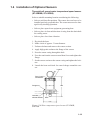
1.4 Installation of Optional Sensors
Through-hull mount water temperature/speed sensor
(ST-02MSB, ST-02PSB)
Select a suitable mounting location considering the following:
• Select a mid-boat flat position. The sensor does not have to be
installed perfectly perpendicular. The sensor must not be damaged in dry-docking operation.
• Select a place apart from equipment generating heat.
• Select a place in forward direction viewing from the drain hole
for cooling water.
• Select a place free from vibration.
1. Dry-dock the boat.
2. Make a hole of approx. 51 mm diameter.
3. Unfasten locknut and remove the sensor section.
4. Apply high grade sealant to the flange of the sensor.
5. Pass the sensor casing through the hole.
6. Face the notch on the sensor toward boat's bow and tighten the
flange.
7. Set the sensor section to the sensor casing and tighten the locknut.
8. Launch the boat and check for water leakage around the sensor.
Locknut
Face "notch"
toward bow.
51
Flange nut
Coat with
silicone sealant.
123
Brim
ø77
Figure 1-26 Water temperature/speed sensor ST-02MSB,
ST02PSB
1-19
Transom mount water temperature sensor
T-02MTB
• Fix the cable at a convenient location with cable clamp.
• When the cable is led in through the transom board, make a
hole of approx. 17 mm diameter to pass the connector. After
passing the cable, fill the hole with a sealing compound.
D
D>50 cm
M5 x 20
Mount sensor
flush with hull bottom.
Figure 1-27 How to install transom mount water temperature
sensor T-02MTB
Thru-hull mount water temperature sensor
T-03MSB
• Select a mid-boat flat position. The sensor does not have to be
installed perfectly perpendicular. The sensor must not be damaged in dry-docking operation.
• Select a place apart from equipment generating heat.
• Select a place in forward direction viewing from the drain hole
for cooling water.
• Select a place free from vibration.
1. Dry-dock the boat.
2. Drill a hole of 25 mm in the hull.
3. Pass the sensor cable through the hull.
4. Pass the rubber washer, washer and locknut onto the cable in
that order.
5. Apply high grade sealant to the sensor flange, sensor and locknut. Tighten the locknut. Do not overtighten it.
6. Launch the boat and check for water leakage around the sensor.
1-20
SENSOR HOLDER
Nut
Locknut
Washer
Rubber washer
Coat with
silicone sealant.
Thickness of wood
plate should be within
25 mm.
HOLDER GUIDE
Figure 1-28 Thru-hull mount water temperature sensor T-03MSB
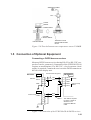
1.5 Connection of Optional Equipment
Connecting a DGPS beacon receiver
Most any DGPS beacon receiver having RS-422 or RS-232C output level can be connected. (Connection of the FURUNO FR-80
requires no modification.) For RS-232C, a level converter (local
supply) is required. Connect the receiver to the DGPS connector at
the rear of the display unit.
GP-1610CF
RS-422
MJ-A7SPF003-050 (option)
DGPS
RD-A
3
RD-B
4
GND
GR-80 DATA
YEL
2
TD-A
GRN
1
TD-B
5
7
GND
6
5
RX-H
7
6
RX-C
RS-422
Current Loop
Note 1
NMEA
Current Loop
TXD-H
1
WHT
TXD-C
2
BLK
3
4
5
6
Note 1:
This cable is required
for Auto L/L mode of
GR-80. It is not
required for Manual
mode.
Figure 1-29 Connection of the FURUNO GR-80 DGPS receiver
1-21
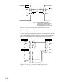
GP-1610CF
BEACON RCVR
DGPS
RD-A
3
YEL
TD-A
RD-B
4
GRN
TD-B
BLU
GND
RS-422
Note 2
5
GND
6
7
F.G
Note 2: The signal names depend on
equipment connected. If data is not
input to the GP-1610CF, change
connection between TD-A and TD-B.
Figure 1-30 Connection of other DGPS beacon receivers
Connecting a sensor
Connect the water temperature sensor or water temperature/speed
sensor to the XDR connector with the converter connector kit (option). This kit contains only a connector; a cable is required.
MJ-A6SRMD
SHIELD
TEMP
TEMP0V
NC
NC
NC
MJ-A10SPF
1
2
3
4
5
6
MJ-A10SRMD
NC
NC
NC
NC
NC
NC
NC
XDR+
XDR SHIELD
XDR-
1
2
3
4
5
6
7
8
9
10
1
4
7
3
2
5
6
8
9
10
Figure 1-31 Wiring of converter connector for water
temperature sensor
1-22
NC
TEMP
TEMP0V
NC
NC
NC
NC
XDR+
XDR SHIELD
XDR-
MJ-A6SRMD
MJ-A10SPF
SHIELD
1
TEMP
TEMP0V/SPD0V
2
4
7
3
3
TEMP0V
SPD0V/ SHIELD
SPD
4
5
1
SPD
2
5
+12.7V
NC
6
NC
XDR+
XDR SHIELD
XDR-
+V
NC
6
MJ-A10SRMD
NC
1
8
9
NC
NC
2
3
10
NC
4
NC
NC
5
6
7
NC
XDR+
XDR SHIELD
XDR-
TEMP
8
9
10
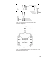
Figure 1-32 Wiring of converter connector for water
temperature/speed sensor
To connector at
rear of display unit
MJ-A10SPF
MJ-A6SRMD
MJ-A10SRMD
Tape connector with
self-vulcanizing tape
and then vinyl tape
to waterproof
connector. Bind tape
end with cable tie.
Water temp., water temp/speed
sensor connector
Transducer connector
Figure 1-33 Connection of transducer, water temperature sensor,
water temperature/speed sensor
1-23
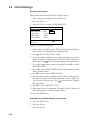
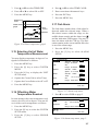
1.6 Initial Settings
Sensor connection
This section should be done with the boat in water.
1. Turn on the power and press the MENU key.
2. Press the [0] key.
3. Press the [5] key to select SENSOR SETUP.
SENSOR SETUP
SPD SENSOR
STW
SOG
TEMP SENSOR
OWN
NMEA
SPD CALIB
-00%(-50~+50)
TEMP CALIB
+000°C
DEPTH CALIB
+0.0m
: Cursor
: +/-
ESC : Esc
Figure 1-34 Sensor setup menu
4. Select source of ship's speed; STW (Speed-Through-Water):
local sensor, SOG (Speed-Over-Ground): GPS.
5. Press ▲ twice to select SPD CALIB.
6. If speed reading is higher or lower than actual speed you may
apply an offset to compensate for this. Enter offset with plus or
minus sign. The
key alternately displays plus and minus.
7. If a water temperature sensor is installed, press ▼ to select
TEMP SENSOR.
8. Press t to select OWN. (NMEA is for water temperature data
from external source.)
9. Press ▼ twice to select TEMP CALIB.
10. If temperature reading is higher or lower than actual temperature you may apply an offset to compensate for this. Enter offset with plus or minus sign. The
key alternately displays
plus and minus.
11. Press ▼ to select DEPTH CALIB.
12. Enter ship's draft, if applicable. Normally, depth is measured
from the transducer so enter positive figure.
13. Press the MENU key.
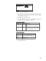
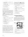
Autopilot or remote display connection
1. Press the MENU key.
2. Press the [0] key.
3. Press the [6] key.
1-24
NMEA SETUP
FORMAT
183V1.5
EXT DEVICE
REM
: Cursor
183V2.0
PILOT
ESC: Esc
Figure 1-35 NMEA setup menu
4. Press t or s to select data format of connected external equipment. If you are not sure, try both and select the one which
successfully receives data.
5. Press ▼ to select EXT DEVICE.
6. Press t or s to select type of external equipment (input and
output data); REMote display or AutoPILOT.
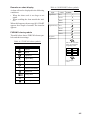
Table 1-1 Output data
Equipment
Talker
Sentences
Autopilot
GP
AAM, APB, BOD, GLL, VTG,
XTE
Remote
display
GP
BWR, DBT (version 1.5), DPT
(version 2.0), GLL, MTW, RMB,
RMC, VTG, ZDA
Table 1-2 Input data
Talker
Sentences
LC, DE, or all GLL, GGA, RMC, RMA, TLL,
talkers
VTG
None
MTW, TLL
7. Press the MENU key.
1-25
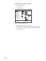
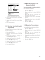
DGPS beacon receiver connection
1. Press the MENU key.
2. Press the [0] key.
3. Press the [8] key.
DGPS SETUP
DGPS
ON
RTCM VER
1.0
2.0
BYTE FORM
8-6
8-8
OFF
FIRST BIT
MSB
LSB
PARITY BIT
EVEN
ODD
STOP BIT
1
2
BIT RATES
7
8
BAUD RATES
300
600
2400
4800
NONE
1200
9600
: Cursor
ENT : Sel
ESC : Esc
Figure 1-36 DGPS setup menu
4. Press t to select ON in the DGPS line.
5. Change settings referring to the operator's manual of the DGPS
beacon receiver. Circumscribed options are standard settings.
6. Press the MENU key.
1-26
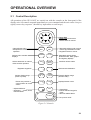
OPERATIONAL OVERVIEW
2.1 Control Description
All operations of the GP-1610CF are carried out with the controls on the front panel of the
display unit. All controls respond immediately to your command and the unit emits a beep to
signify correct key sequence. (Invalid key input emits several beeps.)
Cursor Pad
• Shifts cursor and screen.
• Selects items on menus.
• Opens/closes menu.
• Escapes from current
operation.
MENU
ESC
NU/CU
ENT
Selects video sounder
displays.
SNDR
1
PLTR
6
Selects automatic or manual
video sounder operation.
AUTO
2
EVENT
MOB 7
Inscribes various marks.
Registers waypoints.
WPT
3
GOTO
8
Sets/cancels destination.
ZOOM
IN 4
ZOOM
OUT 9
Shrinks display range
(blows up chart).
Places own position or
cursor position at screen
center.
• Adjusts brilliance.
• Switches +, -, North, South,
East and West.
CNTR
5
TONE
CURS
0
CLR
• Alternately selects north-up and
course-up presentation modes.
• Registers items on menus.
Alternately selects plotter,
plotter/sounder, data, graphic
and highway displays.
Expands display range
(shrinks chart).
Displays/erases cursor.
• Clears data.
• Erases selected waypoint,
mark.
• Silences audible alarm.
POWER
Turns power on/off.
Figure 2-1 Controls
2-1
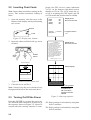
2.2 Inserting Chart Cards
Note: Insert chart card before turning on the
power. This enables automatic loading of
chart.
1. Open the memory card slot cover at the
bottom of the display unit by unfastening
two screws.
pleted, the GPS receiver status indication
"ACQ" (at the bottom right-hand corner)
changes to 2D (or 3D). ACQ means the receiver is acquiring the GPS signal, and 2D
(or 3D) means the position data is reliable.
ROM
RAM
VRAM
Battery
Displayed for
about one second.
OK
OK
OK
OK
Screws
Cover
Program No. = 02522530**
Base Chart No. =
** Program version
no.
Figure 2-2 Display unit, bottom
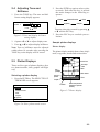
2. Insert the chart card label side up, arrow
forward.
EJECT
button
Chart
card
— — WARNING— —
NO NATIONAL HYDROGRAPHIC
OFFICE HAS VERIFIED THE
INFORMATION IN THIS COASTLINE
DATA CARD AND NONE ACCEPT
LIABILITY FOR THE ACCURACY OF
REPRODUCTION OR ANY
MODIFICATIONS MADE THEREAFTER.
THIS PRODUCT WITH THIS
COASTLINE DATA CARD DOES NOT
REPLACE THE REQUIREMENT TO
USE THE APPROPRIATE PRODUCTS
FOR NAVIGATION ACCORDING TO
NATIONAL AND INTERNATIONAL
REGULATONS.
Displayed for
about one minute.
FURUNO ELECTRIC CO., LTD.
Arrow forward
Plotter display
Figure 2-3 How to insert chart card
3. Close the cover and fix it.
Note: Always keep the cover closed to keep
foreign material out of the chart card drive.
2.3 Turning On/Off the Power
Press the POWER key to turn the power on/
off. When the unit is turned on, it proceeds in
the sequence shown in Figure 2-4. About 20
seconds after the start-up sequence is com-
2-2
BRG+ 232.0° RNG+ 0.00nm ACQ
DEP 110m
TMP 16 .0°C 13:41
+
34°43.801’N 135°21.163’E
GPS Fixing Status
ACQ (Acquiring)
is replaced by
2D or 3D when
position becomes
reliable.
Figure 2-4 Start-up sequence
2D: Ship's position is calcurated by using data
from 3 satellites.
3D: Ship's position is calcurated by using data
from 4 satellites.
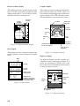
2.4 Adjusting Tone and
Brilliance
1. Press the TONE key. The tone and brilliance setting display appears.
2. Press the PLTR key again to select a plotter mode. Each time the key is pressed
the mode changes in the following sequence:
Plotter
LOW
HIGH
LOW
HIGH
Highway
TONE : 5
BRILL : 8
Figure 2-5 Tone and display brilliance
setting display
2. Operate t or s to adjust display tone.
Plotter/Sounder
Data
Graphic
You may also select a mode by pressing ▲
or ▼ and the ENT key.
3. Press the ESC key to conclude your selection.
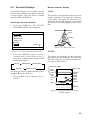
Sample plotter displays
3. Press ▲ or ▼ to adjust display brilliance.
Plotter display
Note: Tone or brilliance must be adjusted
within about 10 seconds after pressing the
TONE key or the display will be erased.
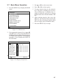
The plotter display mainly shows chart, ship's
track, waypoints, marks and various data.
2.5 Plotter Displays
Course bar
There are five types of plotter displays: plotter, plotter/sounder, data, graphic and highway.
Own ship
mark
Track
Selecting a plotter display
1. Press the PLTR key. The SELECT PLOTTER MODE screen appears.
Icon
(chart)
GPS status
Course,
speed
CSE 180.0° SPD 16.8kt
2D
DEP 110m TMP 16.0°C 12:13
POS 34°26.345’N 135°41.232’E
Depth
Position
SELECT PLOTTER MODE
Time
Water temperature
(Requires optional
sensor.)
Plotter
Figure 2-7 Plotter display
Plotter/Sounder
Data
Graphic
Highway
PLTR: Sel
ESC: Close
Figure 2-6 Select plotter mode screen
2-3
Plotter/sounder display
Graphic display
This display provides a plotter display on the
left 2/3 of the screen an the normal sounder
display on the right 1/3. It is useful for searching fish schools at cruising speed.
This display provides analog and digital displays of cross track error (XTE), course, etc.
It is useful for monitoring progress when steering by autopilot. The XTE scale shows direction and amount to steer to return to course.
Sounder
Display
Plotter
Display
Position
POS
0
50
34° 26.345°N
135° 38.417' E
W
Course
Course
indicator
S
100
150
Bearing to
waypoint
BRG
Course
set
248°
CSE
200k
200
Distance
run
CSE 180.0° SPD 16.8kt
2D
DEP 110m TMP 16.0°C 12:13
POS 34°26.345’N 135°41.232’E
Figure 2-8 Plotter/sounder display
323°
1nm
TRIP
ETA
21.0 nm
23: 20
RNG
112 nm
TTG
14H 20M
Estimated time of
arrival at waypoint
This display provides various navigation data,
such as position, course and speed, in digital
form.
Date
1997.01.21 12:13
34° 26.345' N
135°38.417' E
CSE
110m
Position
SPD
127.1 ° 16.8 kt
DEP
TMP
15.2 °C
WP 001
RNG 173.4 nm
BRG 180.0°
XTE
0.25 nm
Figure 2-10 Graphic display
Highway display
The highway display provides a graphic presentation of ship’s track along a course. It is
useful for monitoring XTE-the XTE scale
shows direction and amount in nautical miles
to steer to return to course.
Course,
speed
Depth, water
temperature
Waypoint
15
Waypoint no.
Range to waypoint
Bearing to waypoint
Cross-track error
Figure 2-9 Data display
01
10
Own ship
mark
5
North
mark
5
5
WP001 120.6° 2.2nm
CSE 180.0° SPD 16.8kt
2D
DEP 113.6 m TMP 16.0°C 12:13
POS 34°26.345'N 135°41.232'E
XTE
scale
Bearing and range
to waypoint
Figure 2-11 Highway display
2-4
Range to
waypoint
Time-to-go to
waypoint
Data display
POS
XTE
scale
1nm
2.6 Sounder Displays
Normal sounder display
Five sounder displays are available: normal,
marker zoom, bottom zoom, bottom-lock and
A-scope display. You may select a sounder
display with the SNDR key.
50 kHz
Selecting a sounder display
1. Press the SNDR key. The SELECT
SOUNDER MODE screen appears.
The sounder uses ultrasonic pulses to detect
seabed conditions. The lower the frequency
of the pulse, the wider the detection area.
Therefore, the 50 kHz frequency is useful for
general detection and judging seabed condition.
SELECT SOUNDER MODE
50 kHz
Normal
Marker Zoom
200 kHz
Bottom Zoom
Bottom Lock
A-Scope
50kHz
200kHz
SNDR: Sel
ESC: Close
Figure 2-12 Select sounder mode screen
2. Press the SNDR key again to select a
sounder mode. Each time the key is
pressed the sounder mode changes in the
following sequence:
Normal
A-Scope
Marker Zoom
Figure 2-13 Detection area
200 kHz
The higher the frequency of the ultrasonic
pulse the better the resolution. Therefore, the
200 kHz frequency is ideal for detailed observation of fish schools.
Bottom Zoom
Bottom-Lock
You may also select a sounder mode by pressing ▲ or ▼ and the ENT key.
3. Press the ESC key to conclude your selection.
Water temp. display
Temp.
scale
Water
temp.
graph
Depth scale
°C
30
0
20
50
10
68.3
0
100
Color
bar
Depth
150
200
162
Variable
Range
Marker
(white)
Fish
school
Bottom
200k
CSE 180.0°
SPD 16.8kt
2D
DEP 162m
TMP 16.0 °C
13:41
POS 34° 26.245' N
135° 41.232' E
Tx
frequency
Figure 2-14 Typical 200 kHz normal
sounder display
2-5
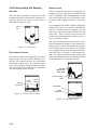
Marker zoom display
Bottom-lock display
This mode expands anywhere of the normal
picture to full vertical size of the screen on
the left-half window. You may specify the
portion to expand by operating the VRM
(Variable Range Marker), which you can shift
with ▲ or ▼. The segment between the VRM
and zoom range markers are expanded. The
length of the segment is equal to one division
of the depth scale.
The bottom-lock display provides a compressed normal picture on the right half of the
screen and a 5 or 10 meter wide layer in contact with the seabed is expanded onto the left
half of the screen. (You may select layer width
on the SOUNDER SETUP menu in the SYSTEM menu.) This mode useful for bottom
discrimination.
This part
is zoomed.
Fish school
Marker zoom
display
Normal
display
0
100
Fish
school
50
VRM
(white)
90.0
100
150
200k
CSE 180.0°
SPD 16.8kt
2D
DEP 162m
TMP 16.0 °C
13:41
POS 34° 26.245' N
Expansion
range
marker
(yellow)
135° 41.232' E
Figure 2-15 Marker zoom display
plus normal display
Bottom zoom display
This mode expands bottom and bottom fish
echoes two to five times to vertical size of the
screen. This mode is useful for determining
bottom hardness. A bottom displayed with a
short echo tail usually means it is a soft, sandy
bottom. A long echo tail means a hard bottom.
0
100
40.0
Bottom zoom
display
Fish
school
Fish
school
20
100
100
140
162
150
160
Normal
display
150
200
0
200k
CSE 180.0°
SPD 16.8kt
2D
DEP 162m
TMP 16.0 °C
14:02
POS 34° 26.245' N
135° 41.232' E
Figure 2-17 Bottom-lock display plus
normal display
Note: The expansion marker is not displayed
in the defualt setting. It may be turned on in
the SNDR SETUP menu in the SYSTEM
menu.
A-scope display
This display shows echoes at each transmission with amplitudes and tone proportional to
their intensities, on the right 1/3 of the screen.
It is useful for estimating the kind of fish
school and seabed composition.
Normal
display
Expansion
range
marker
(yellow)
Expansion
range
marker
(yellow)
10
0
A-scope
display
50
68.3
162
68.3
50
120
Bottom
100
Normal
display
150
200
200k
180
CSE 180.0°
SPD
Display is
DEP 162m
TMP
blown up
POS 34° 26.245' N
three times
larger than
normal display.
16.8kt
2D
16.0 °C
14:02
135° 41.232' E
Figure 2-16 Bottom zoom display plus
normal display
2-6
50
30
200
200
0
50
40
This part
is zoomed.
150
162
Bottom-lock
display
160
200
200k
CSE 180.0°
SPD 16.8kt
2D
DEP 160m
TMP 16.0 °C
14:02
POS 34° 26.245' N
135° 41.232' E
Figure 2-18 A-scope display (right side)
2.7 Basic Menu Operation
1. Press the MENU key to display the MAIN
menu.
MAIN MENU
1. DISPLAY SETUP
2. TRACK/MARK SETUP
3. ERASE TRACK/MARK
3. Press ▲ or ▼ to select menu item.
4. Press t or s to select option.
5. To enter numeric data use the numeric
keys. The entry of leading zero is necessary; trailing zero is optional. For example, to enter 050, press [0] [5]. Wrong
numeric data can be cleared with the CLR
key.
6. After entering numeric data, press the
ENT key. (It is not necessary to press the
ENT key after selecting an option which
does no require entry of numeric data.)
4. ROUTE/ROUTE LIST
5. ALARM SETUP
6. VIDEO SOUNDER SETUP
7. MEMORY SAVE/LOAD
8. CLEAR MEMORY
7. Press the MENU key to escape.
0. SYSTEM MENU
: Cursor
ESC: Esc
Figure 2-19 Main menu
2. Press appropriate numeric key or ▲ or ▼
and ENT key to select menu desired. The
highlighted cursor shifts with numeric key
or Cursor Pad operation. For example,
press the [1] key to display the DISPLAY
SETUP menu.
DISPLAY SETUP
1
HUE
2
LAND BRILL
BRT
DIM
LAND COLOR
RED YEL GRN BLU PPL WHT OFF
PLACE NAME
RED YEL GRN BLU PPL WHT OFF
GRID COLOR
RED YEL GRN BLU PPL WHT OFF
COURSE BAR
RED YEL GRN BLU PPL WHT OFF
TIME MARK
RED YEL GRN BLU PPL WHT OFF
WPT MARK SIZE L
S
CURSOR SIZE
S
: Cursor
L
OFF
ESC: Esc
Figure 2-20 Display setup menu
2-7
VIDEO SOUNDER OPERATION
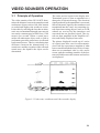
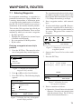
3.1 Principle of Operation
The video sounder of the GP-1610CF determines the distance between its transducer and
underwater objects such as fish, lake bottom
or seabed and displays the results on screen.
It does this by utilizing the fact that an ultrasonic wave transmitted through water travels
at a nearly constant speed of 4800 feet ( 1500
meters) per second. When a sound wave
strikes an underwater object such as fish or
sea bottom, part of the sound wave is reflected
back toward source. Thus by calculating time
difference between the transmission of a
sound wave and the reception of the reflected
sound wave, the depth to the object can be
determined.
The entire process begins in the display unit.
Transmitter power is sent to transducer as a
short pulse of electrical energy. The electrical
signal produced by the transmitter is converted
into an ultrasonic signal by the transducer and
transmitted into the water. Any returning signals from intervening objects (such as a fish
school) are received by the transducer and
converted into an electrical signal. The signals are then amplified in the amplifier section, and finally, displayed on screen.
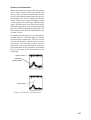
The picture displayed is made up of a series
of vertical scan lines, one for each transmission. Each line represents a snapshot of what
has occurred beneath the boat. Series of snapshots are accumulated side by side across
screen, and the resulting contours of the bottom and fish between the bottom and surface
are displayed.
Figure 3-1 Underwater conditions and video sounder display
3-1
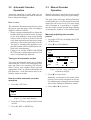
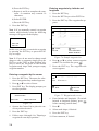
3.2 Automatic Sounder
Operation
3.3 Manual Sounder
Operation
Automatic operation is useful when you are
preoccupied with other tasks and do not have
time to adjust the display.
Manual operation is useful for observing fish
schools and bottom using fixed gain setting.
How it works
The automatic function automatically selects
the proper gain and range scale according to
depth. It works as follows:
• Range changes automatically to locate the
bottom on the lower half of screen. It jumps
to one step shallower range when bottom
echoes reach a half way point of the full
scale from top and to one step deeper range
when they come to the lower edge of scale.
• The gain is automatically adjusted to display the bottom echo in reddish brown (default color arrangement).
• Clutter level, (on the VIDEO SOUNDER
SETUP menu), which suppresses low level
noise, is automatically adjusted.
The gain, range and range shifting functions
used together give you the means to select the
depth you can see on screen. The basic range
can be thought of as providing a "window"
into the water column and the range shifting
as moving the "window" to the desired depth.
Manually adjusting the sounder
picture
1. Press the AUTO key to display the AUTO
MODE menu.
2. Press ▼ to select Manual.
AUTO MODE
Cruise
Fish
Manual
Low
Two types of automatic modes
Two types of automatic modes are available:
cruise and fish. Cruise is for tracking the bottom, and fish is for searching fish schools.
Since "Cruise" uses a higher clutter rejection
setting than "Fish," it is not recommended for
fish detection – weak fish echoes may be deleted by clutter rejection.
How to enable automatic sounder
operation
1. Press the AUTO key.
High
Gain
Range
40
Shift
5
10
80
160
0m
Figure 3-3 Gain, range and shift
adjustment display
3. Press ▼ to select Gain.
Normally, set the gain to the point where
excessive noise does not appear on screen.
Use a higher gain setting for greater depths
and a lower setting for shallower waters.
4. Press t or s to set level.
AUTO MODE
Cruise
Fish
Manual
Figure 3-2 Auto mode display
2. Press the AUTO key again to select Cruise
or Fish.
3. Press the ENT or MENU key.
3-2
20
300 m
MAIN MENU
1. DISPLAY SETUP
2. TRACK/MARK SETUP
3. ERASE TRACK/MARK
4. ROUTE/ROUTE LIST
5. ALARM SETUP
6. VIDEO SOUNDER SETUP
Too high
Proper
Too low
Figure 3-4 Examples of proper
and improper gain
5. Press ▲ to select Range.
7. MEMORY SAVE/LOAD
8. CLEAR MEMORY
0. SYSTEM MENU
: Cursor
6. Press t or s to select basic range desired.
7. Press ▼ to select Shift.
ESC: Esc
Figure 3-6 Main menu
2. Press the [6] key to display the VIDEO
SOUNDER SETUP menu.
VIDEO SOUNDER SETUP
CLUTTER 0 1 2 3
AUTO
ADVANCE STOP 1/8
1/4
1/2
1/1
2/1
NL1
NOISE LM OFF
NL2 NL3
Shift
DEP CHIME ON
TEMP GRP ON
SIG LEV
SL0
ZOOM
X2
Display
Figure 3-5 Shift concept
8. Press t or s to shift the basic range, if
desired.
9. Press the MENU key.
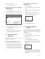
3.4 Suppressing Low Level
Noise
Light-blue dots may appear over most of
screen. This is mainly due to dirty water or
noise. This noise can be suppressed by adjusting CLUTTER on the VIDEO SOUNDER
SETUP menu.
1
HUE
3 4
40
80
OFF
OFF
SL1
X3
X4
2
0
SL2
120
X5
5
2D
5:55
65 E
: Cursor
ESC : Esc
Figure 3-7 Video sounder setup menu
3. Press ▲ to select CLUTTER.
4. Press t or s to select clutter rejection
level desired; 0 (OFF), 1, 2, 3 or AUTO.
The higher the number the higher the degree of suppression. Note that weak echoes may not be displayed when the clutter
circuit is on.
5. Press the MENU key.
When the sounder mode is Auto, the clutter
suppression setting is fixed at AUTO. To suppress low level noise in manual sounder operation do the following:
1. Press the MENU key.
Clutter
Clutter removed
Figure 3-8 How the clutter function works
3-3
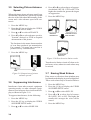
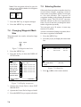
3.5 Selecting Picture Advance
Speed
When selecting a picture advance speed, keep
in mind that a fast advance speed will expand
the size of the fish school horizontally on the
screen and a slow advance speed will contract it.
4. Press t or s to select degree of suppression desired; OFF, NL1, NL2 or NL3. The
higher the number the greater the degree
of suppression.
5. Press the MENU key.
1. Press the MENU key.
2. Press the [6] key to display the VIDEO
SOUNDER SETUP menu.
3. Press ▲ or ▼ to select ADVANCE.
4. Press t or s to select advance speed (a
"fraction") desired, or STOP to suspend
advancement of the picture.
Electrical
interference
Interference from
other sounder
The fractions in the menu denote number
of scan lines produced per transmission.
For example, 1/8 means one scan line is
produced every 8 transmissions.
5. Press the MENU key.
Noise limiter
turned on
Figure 3-10 How the noise limiter works
Turn the noise limiter circuit off when no interference exists, otherwise weak echoes may
be missed.
Fast
Slow
Figure 3-9 Comparison of picture
advance speeds
3.6 Suppressing Interference
3.7 Erasing Weak Echoes
Dirty water or reflections from plankton may
be painted on the display in green or light blue.
These weak echoes may be erased as follows:
1. Press the MENU key.
Interference from other acoustic equipment
operating nearby or other electronic equipment on your boat may show itself on the display as shown in Figure 3-10.
2. Press the [6] key to display the VIDEO
SOUNDER SETUP menu.
To suppress interference, do the following:
4. Press t or s to select level of erasure;
SL0 (OFF), SL1 or SL2. The higher the
number the stronger the echo will be
erased.
1. Press the MENU key.
2. Press the [6] key to display the VIDEO
SOUNDER SETUP menu.
3. Press ▲ or ▼ to select NOISE LM.
3-4
3. Press ▲ or ▼ to select SIG LEV.
5. Press the MENU key.
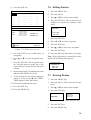
3. Press ▲ or ▼ to select HUE.
Weak
echoes
Signal level
adjusted
4. Press t or s to select hue arrangement
number. (A portion of the sounder display
appears so you may see the result of your
selection.)
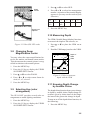
Hue
1
2
3
4
5
Bkgd
color
Blue
Light
blue
Black
Green
Black
5. Press the MENU key.
3.10 Measuring Depth
The VRM (Variable Range Marker) functions
to measure the depth to fish schools, etc.
Figure 3-11 How SIG LEV works
3.8 Changing Zoom
Magnification Factor
1. Press ▲ or ▼ to place the VRM on an
echo.
2. Read the VRM range just above the VRM.
0
You may select the zoom magnification factor for the marker and bottom zoom modes.
This the amount the zoomed picture is magnified in relation to the normal picture.
1. Press the MENU key.
2. Press the [6] key to display the VIDEO
SOUNDER SETUP menu.
3. Press ▲ or ▼ to select ZOOM.
4. Press t or s to select zoom factor desired; x2, x3, x4 or x5.
5. Press the MENU key.
3.9 Selecting Hue (color
arrangement)
The GP-1610CF provides several color arrangements to match lighting conditions.
Depth of
VRM
40
58.3
VRM
80
120
160
132
200k
CSE 180.0°
SPD 16.8kt
2D
DEP 132m
TMP 16.0 °C
14:32
POS 34° 26.245' N
135° 41.232' E
Figure 3-12 How to measure
depth with the VRM
3.11 Knowing Depth Change
by Audible Chime
The depth chime function alerts you to change
in depth by audible chime Depth change direction is given by chime interval; the longer
the interval the greater the change in depth.
1. Press the MENU key.
To turn on or off the depth chime function, do
the following:
2. Press the [6] key to display the VIDEO
SOUNDER SETUP menu.
1. Press the MENU key.
3-5
2. Press the [6] key to display the VIDEO
SOUNDER SETUP menu.
SYSTEM MENU
3. Press ▲ or ▼ to select DEP CHIME.
2. PLTR SETUP
4. Press t or s to select ON or OFF.
1. SELF TEST
3. SOUNDER SETUP
4. UNIT SETUP
5. Press the MENU key.
5. SENSOR SETUP
6. NMEA SETUP
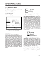
7. GPS SETUP
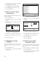
3.12 Selecting Unit of Depth
Measurement
You may display the depth in meters, feet or
fathoms as follows:
1. Press the MENU key.
2. Press the [0] key to select SYSTEM
MENU.
3. Press the [4] key to display the UNIT
SETUP menu.
UNIT SETUP
DISTANCE
nm
km
sm
DEPTH
m
ft
fa
TEMP
°C
°F
8. DGPS SETUP
9. CHART POSN CALIB
: Cursor
ENT: Sel
ESC: Esc
Figure 3-14 System menu
3. Press the [5] key to select SENSOR
SETUP.
SENSOR SETUP
SPD SENSOR
STW
SOG
TEMP SENSOR
OWN
NMEA
SPD CALIB
+00%(-50~+50)
TEMP CALIB
+00.0 °C
DEPTH CALIB
+0.0 m
: Cursor
: Cursor
ESC: Esc
: +/-
ESC: Esc
Figure 3-13 Unit setup menu
Figure 3-15 Sensor setup menu
4. Operate the Cursor Pad to select Depth.
4. Press ▲ or ▼ to select DEPTH CALIB.
5. Operate the Cursor Pad to select m, ft, or
fa.
5. Enter correction with numeric keys.
6. Press the MENU key.
7. Press the MENU key.
3.13 Offsetting the Depth
Readout
3.14 Displaying the Water
Temperature Graph
If the depth displayed is not correct you may
offset to it to correct the correct value as follows:
A water temperature graph can be displayed.
This function requires a water temperature
sensor.
1. Press the MENU key.
To turn on/off the water temperature graph:
2. Press the [0] key to select the SYSTEM
SETUP menu.
1. Press the MENU key.
6. Press the ENT key.
2. Press the [6] key to display the VIDEO
SOUNDER SETUP menu.
3-6
3. Press ▲ or ▼ to select TEMP GRP.
4. Press ▲ or ▼ to select TEMP CALIB.
4. Press t or s to select ON or OFF.
5. Enter correction with numeric keys.
5. Press the MENU key.
6. Press the ENT key.
7. Press the MENU key.
Water temp.
scale
°C
30
0
20
Water temp.
graph
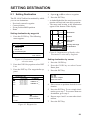
3.17 Fish Alarm
50
10
68.3
0
100
150
Fish
school
Bottom
200
162
200k
CSE 180.0°
SPD 16.8kt
2D
DEP 162m
TMP 16.0 °C
14:32
POS 34° 26.245' N
135° 41.232' E
Figure 3-16 Water temperature graph
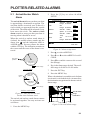
The fish alarm sounds when a fish school is
detected within the selected range. When a
fish school comes within the range set the
audible alarm sounds and the alarm icon
and the indication FISH appear. You may silence the alarm with the CLR key. The indication remains on the screen until the fish echo
is out of the alarm range.
1. Press the MENU key.
3.15 Selecting Unit of Water
Temperature Measurement
You may display temperature in degrees Centigrade or Fahrenheit as follows:
1. Press the MENU key.
2. Press the [0] key to select SYSTEM
MENU.
2. Press the [5] key to select ALARM
SETUP.
ALARM SETUP
ARRIVAL ANCHOR OFF
Range 00.500nm
XTE
ON
OFF
Range 00.250nm
SPEED
WITHIN
OFF
OVER
Speed 11.0~15.0kt
3. Press the [4] key to display the UNIT
SETUP menu.
TEMP
4. Operate the Cursor Pad to select Temp.
TRIP
WITHIN
Temp
ON
5. Operate the Cursor Pad to select °C or °F.
OVER
OFF
+11.0~+15.0°C
OFF
Range 0005.00nm
: Cursor
6. Press the MENU key.
3.16 Offsetting Water
Temperature Readout
1/2
ARRIVAL
ESC: Esc
Figure 3-17 Alarm setup menu
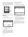
3. Press ▼ to select FISH on page 2.
ALARM SETUP
In some instances the water temperature readout may be off by a few degrees. You can offset it to the correct temperature as follows:
FISH
NORM
B/L
BOTTOM
3. Press the [5] key to select SENSOR
SETUP.
ON
B/L
OFF
003.4~004.6m
OFF
Range 003.4~004.6m
1. Press the MENU key.
2. Press the [0] key to select the SYSTEM
SETUP menu.
2/2
: Cursor
ESC: Esc
Figure 3-18 Alarm setup menu, page 2
3-7
4. Press s or t to select NORMAL or B/L
(Bottom Lock).
5. Press ▼ to send the cursor to the second
line (Range or B/L).
sounds and the alarm icon
and the indication TEMP appears on the display. The indication remains on the display until the
temperature is no longer in the alarm range.
6. Key in the depth desired.
1. Press the MENU key.
7. Press the ENT key.
2. Press the [5] key to select ALARM
SETUP.
8. Press the MENU key.
3.18 Bottom Alarm
The bottom alarm sounds when the seabed
depth is narrower than the alarm range set.
When the bottom echo enters the alarm range
set the audible alarm sounds and the alarm
icon
and the indication DEPTH appears.
You can silence the audible alarm with the
CLR key. The DEPTH indication remains on
the screen until the bottom echo goes out of
the alarm range.
1. Press the MENU key.
2. Press the [5] key to select ALARM
SETUP.
3. Press ▼ to select BOTTOM on page 2.
4. Press t to select ON.
5. Press ▼ to send the cursor to the fourth
line (Range).
3. Press ▲ or ▼ to select TEMP.
4. Press s or t to select WITHIN or
OVER.
5. Press ▼ to send the cursor to the eighth
line (Temp).
6. Key in the temperature desired.
7. Press the ENT key.
8. Press the MENU key.
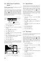
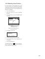
3.20 Turning On/Off the
Expansion Range Marker
The expansion range marker appears in the
normal display picture in the bottom marker
and bottom zoom displays and marks the area
which is expanded in the bottom marker and
bottom zoom pictures. You may turn the
marker on or off as follows:
Fish school
6. Key in the range desired.
7. Press the ENT key.
Marker zoom
display
0
100
Fish
school
8. Press the MENU key.
50
90.0
100
Normal
display
VRM
(white)
150
150
3.19 Water Temperature Alarm
162
CSE 180.0°
The water temperature alarm sounds when the
water temperature is within (or over) the preset temperature range. This alarm is useful for
searching for specific species of fish, since
each species of fish has its own habitable water
temperature. (This alarm requires connection
of a water temperature sensor.)
When the water temperature becomes within
(or over) the alarm range the audible alarm
3-8
DEP 162m
200
200
200k
SPD 16.8kt
TMP 16.0 °C
POS 34° 26.245' N
This part
is zoomed.
2D
13:41
135° 41.232' E
Expansion
range
marker
(yellow)
Figure 3-19 Marker zoom display
1. Press the MENU key.
2. Press the [0] key to select SYSTEM
MENU.
3. Press the [3] key to display the
SOUNDER SETUP menu.
SNDR SETUP
EXP MARKER ON
GAIN ADJ
OFF
(-20~+20)
50k
+00
200k
+00
BTM-LOCK
NARROW WIDE
TRANSMIT
ON
OFF
: Cursor
ESC: Esc
Figure 3-20 Sounder setup menu
4. Operate the Cursor Pad to select EXP
MARKER.
5. Operate the Cursor Pad to select ON or
OFF.
3.22 Selecting Bottom-Lock
Expansion Width
The expansion width for the bottom-lock display can be selected to narrow (5 meters) or
wide (10 meters) as follows:
1. Press the MENU key.
2. Press the [0] key to select SYSTEM
MENU.
3. Press the [3] key to display the
SOUNDER SETUP menu.
4. Operate the Cursor Pad to select BTMLOCK.
5. Operate the Cursor Pad to select NARROW or WIDE.
6. Press the MENU key.
6. Press the MENU key.
3.21 Receiver Sensitivity (gain)
Adjustment
If the gain effect is too low or too high, it may
be offset as follows:
1. Press the MENU key.
2. Press the [0] key to select SYSTEM
MENU.
3. Press the [3] key to display the
SOUNDER SETUP menu.
4. Operate the Cursor Pad to select 50k.
5. Press t or s to adjust level.
3.23 Stopping Transmission
You may disable transmission as follows:
1. Press the MENU key.
2. Press the [0] key to select SYSTEM
MENU.
3. Press the [3] key to display the
SOUNDER SETUP menu.
4. Operate the Cursor Pad to select TRANSMIT.
5. Operate the Cursor Pad to select OFF.
6. Press the MENU key.
6. Operate the Cursor Pad to select 200k.
7. Press t or s to adjust level.
8. Press the MENU key.
3-9
3.24 Interpreting the Display
Bottom echo
Zero line
Echoes from the bottom are normally the
strongest and are displayed in reddish brown
color (in default color arrangement) but the
color and width will vary with bottom composition, water depth, frequency, sensitivity,
etc.
The zero line (sometimes referred to as the
transmission line) represents the transducer’s
position, and moves off the screen when a
deep phased range is used.
In a comparatively shallow depth, a high gain
setting will cause a second or sometimes a
third or a fourth echo to be displayed at the
same interval between them below the first
echo trace. This is because the echo travels
between the bottom and the surface twice or
more in shallow depths.
Zero
line
Shift
Figure 3-21 Zero line
Fish school echoes
Fish school echoes will generally be plotted
between the zero line and the bottom. Usually the fish school/fish echo is weaker than
the bottom echo because its reflection property is much smaller compared to the bottom.
The size of the fish school can be ascertained
from the density of the display.
The color of the bottom echo can be used to
help determine the density of the bottom materials (soft or hard). The harder the bottom,
the wider the trace. If the gain is set to show
only a single bottom echo on mud, rocky bottom will show a second or third bottom return. The range should be chosen so the first
and second bottom echoes are displayed when
bottom hardness is being determined.
Intensity
difference in
water depth
Second bottom
echo
Size of
fish school
Small
school
Large
school
Rock base
Mud
and sand
Figure 3-22 Fish school echoes
Figure 3-23 Bottom echoes
3-10
Surface noise/aeration
When the waters are rough or the boat passes
over a wake, surface noise may appear near
the zero line. As surface turbulence is acoustically equivalent to running into a brick wall,
the bottom echo will be displayed intermittently. Similar noise sometimes appears when
a water temperature difference (thermocline)
exists. Different species of fish tend to prefer
different temperature zone, so the thermocline
may be useful to help identify target fish. 200
kHz tends to show shallow thermoclines better than 50 kHz.
In rough waters the display is occasionally interrupted due to below-the-ship air bubbles
obstructing the sound path. This also occurs
when the boat makes a quick turn or reverses
movement. Lowering the picture advance
speed may reduce the interruption. However,
reconsideration of the transducer installation
may be necessary if the interruption occurs
frequently.
Surface noise
Caused by
aerated water
Thermocline
Figure 3-24 Surface noise/aeration
3-11
GPS, CHART OVERVIEW
How the GPS receiver calculates
position
4.1 Principle of GPS
What is GPS?
The GPS receiver’s position is continuously
fixed by receiving 3 (or 4) satellites in lineof-sight of the GPS receiver. The basic steps
in position fixing are as below:
GPS is an acronym meaning Global Positioning System. GPS (sometimes referred to as
NAVSTAR) is a highly precise satellite navigation system developed by the U.S. Department of Defense.
1) GPS satellites continually transmit their
own precise orbital data called ephemeris.
The GPS receiver computes satellites’
position by this data.
A constellation of 24 satellites emplaced in
nearly 20,000-kilometer high 12-hour circular orbits provides highly precise, continuous,
worldwide, all-weather position plus time and
velocity information to GPS receiverequipped vehicles, vessels and aircraft.
2) The GPS receiver measures very accurate
distance to the satellites.
3) Satellite positions and their distances from
the GPS receiver are known. The point of
intersection of the satellites used in fixing
position.
1 Satellite locations are
calculated.
2 Distances are measured.
3 The GPS fix is the point
of intersection of three
spheres which are drawn
around the three satellites
with diameter d1, d2, and d3.
d2
d3
d1
GPS fix
Figure 4-1 How GPS determines position
4-1
Position-fixing accuracy (HDOP)
In radar position-fixing, most accurate position fixes are obtained when the targets used
are spaced nearly 90° from each other. Similarly, GPS position fixing accuracy is subject
to satellite location. Generally, the further
apart the satellites are from one another, the
greater the position-fixing accuracy.
For example, take a look at Figure 4-2. In both
situations a fix is obtainable in the Northern
Pacific region because three satellites are in
line-of-sight. However, accuracy will be
higher in the bottom figure since the satellites
are spread farther apart than the satellites in
the top figure.
The index for position-fixing accuracy is
known as HDOP (Horizontal Dilution of Precision). In simpler terms it is the geometrical
relationship among 3 (or 4) satellites. The
higher the HDOP value the less accurate the
position fix. The error in distance is proportional to the HDOP value as shown in Figure
4-3.
ERROR (RMS)
60 m
45 m
30 m
15 m
DOP
3
6
9
12
Figure 4-3 HDOP rate and position error
In this manual HDOP is referred to as DOP.
Low accuracy
High accuracy
Figure 4-2 Satellite positions and
accuracy of position fix
4-2
4.2 Presentation Mode
4.3 Shifting the Cursor
Two types of display presentations are provided for the plotter display and plotter/
sounder display: north-up and course-up. You
can select one with the NU/CU key.
l.
Press the CURS key to turn the cursor on.
2. Operate the Cursor Pad. The cursor moves
in the direction the Cursor Pad is pressed.
When the cursor reaches an edge of the
screen, the display is scrolled.
North-up
North (zero degrees) is at the top of the display and own ship is at the center of the screen.
This mode is useful for long-range navigation.
Own ship
mark
Own ship
mark
Bearing and
range from
own ship
to cursor
Cursor
(Size can
be selected
to large or
BRG+ 132.0° RNG+ 5.0mm 2D
small. Size
DEP 110m TMP 16.0°C 14:05
shown is
+
32°10.523’N 133°27.254’E
large.)
Cursor position
in latitude and
longitude
Figure 4-6 Plotter display, showing
location of cursor data
CSE 340.0° SPD 16.8kt
2D
DEP 110m TMP 16.0°C 14:05
POS 34°26.345’N 135°41.232’E
Figure 4-4 North-up display
When the cursor is turned off, own ship data
is shown instead of cursor data.
Course-up
When destination is set it is at the top of the
screen, the north mark appears at the lower
left side of the screen and points to north. A
triangle marks own ship's position.
01
North
mark
Destination
Own ship
mark
WP001 0° 10nm
CSE 10.0°
SPD 16.8kt
2D
DEP 110m TMP 16.0°C 14:08
POS 34°26.345’N 135°41.232’E
Own ship
mark
Course,
speed
CSE 340.0° SPD 16.8kt
2D
DEP 110m TMP 16.0°C 14:05
POS 34°26.345’N 135°41.232’E
Position
Figure 4-7 Plotter display, showing
location of own ship's data
Bearing and
range to
waypoint
Figure 4-5 Course-up display
4-3
4.4 Selecting Screen Center
by Cursor
1. Press the CURS key to display the cursor.
2. Operate the Cursor Pad to place the cursor where desired.
3. Press the CNTR key.
4.5 Shifting the Display
1. Press the CURS key to turn off the cursor.
2. Operate the Cursor Pad to shift the display.
4.6 Centering Position
When a wrong card is inserted or a wrong
chart scale is selected, the land will be hollow. Insert the proper card and select a suit
able chart scale. Chart icons appear to help
you select suitable chart scale. Table 4-1 explains the chart icons and their meanings.
Table 4-1 Chart icons and their meanings
Icon
Meaning
Proper card is not inserted
or chart scale is too small.
Press the ZOOM OUT key
to adjust chart scale.
Chart scale is too large.
Press the ZOOM IN key
to adjust chart scale.
Suitable chart scale is
selected.
1. Press the CURS key to turn off the cursor.
2. Press the CNTR key.
4.7 Changing Chart Scale/
Range
Chart scale (range) may be selected with the
ZOOM IN and ZOOM OUT keys. The
ZOOM IN key blows up the chart; the ZOOM
OUT key shrinks it.
Indices and chart enlargement
When the ZOOM OUT key is pressed you
will see several frames. These frames are
called indices and they show you what parts
of the chart can be enlarged in the current picture range. The areas circumscribed with
smaller frames can be enlarged, but the area
enclosed by the largest frame cannot.
Note: When the display is blown up or shrunk
beyond the range of the chart card in use the
message NO CHART appears to alert you.
4.8 Chart Cards
The chart cards contain nautical charts. When
you insert a suitable chart card in the drive
and your boat is near land, a chart appears
with the land portion arranged according to
the "land settings" in the DISPLAY SETUP
menu.
4-4
Figure 4-8 Sample chart (Japan and
South Korea) showing indices
Remarks on chart display
A chart will not be displayed in the following
conditions:
• When the chart scale is too large or too
small.
• When scrolling the chart outside the indices.
When this happens, the message NO CHART
appears for a couple of seconds. The icon also
appears.
Table 4-3 NAVIONICS chart symbols
Type
Lighthouse
Color
Symbol
Red
R
Green
G
White
W
Others
¡
Lighted-buoy Red
R
Green
G
White
FURUNO chart symbols
The table below shows FURUNO charts symbols and their meanings.
W
Others
Foghorn
★
Lighthouse
R
Table 4-2 FURUNO chart symbols
Symbol
Description
Summit
Wreck
Lighthouse
R
The arc is viewable
range and alphabet
is lighting color.
Red
Green
White
Orange
R Cyan
C
G Yellow Y
W Blue
B
O
R
Lighted Buoy
Buoy
For multiple
colors
Radio Station
Position of Sounding
Obstruction
Fishing Reef
Platform
Anchorage
4-5
Difference between FURUNO and
NAVIONICS charts
Table 4-4 Comparison of chart systems
Item
FURUNO
NAVIONICS
Dot scrolling
capability
YES
YES
Course-up
display
YES
NO
Lighthouse data
presentation
YES *3
YES
Zoom at cursor
position
YES
*1
Range at
Equator
1, 1.5, 2,
3, 4, 5, 6,
8,
12...8192
nm
0.125, 0.25,
0.5, 1, 2, 3, 4,
8...1024 nm
Chart offset
data entry
YES
NO
Centering
YES
You can find data of lighthouses and buoys
by placing the cursor on them. Lighthouse and
buoy data are displayed as shown in Figure
4-9.
Lighthouse or
buoy data
FL 12S 27M
Place the cursor on
a lighthouse or buoy mark.
Example of data displayed
FL(2) G 12S 15M
Visibility in nautical
mile (ex.: 15 miles)
*2
*1 NAVIONICS chart may not center cursor
perfectly.
*2 NAVIONICS chart may not center own
ship’s position perfectly.
*3 Newly designed chart cards containing
lighthouse data. Chart cards for North
America area are completed, and others
are in production.
4-6
Lighthouse and buoy data display
Period (ex.: 12 seconds)
Light color
Number of flashes per period (ex.:2)
FL
F
F FL
MO
Oc
: Flashing
: Fixed light
: Fixed and Flashing light
: Morse code light
: Occulting light
Figure 4-9 Lighthouse and buoy data
TRACK
5.1 Stopping/Restarting
Plotting of Track
Hollow own ship
mark means track
plotting has been
stopped.
When your boat is at anchor or returning to
port you probably won't need to record its
track. You can stop recording the track, to
conserve the track memory, as follows:
l.
Own ship mark
Track not
recorded
is not plotted.
Press the MENU key.
Track plotting
stopped
2. Press the [2] key to select TRACK/
MARK SETUP. The track/mark setup
menu appears.
Track plotting
restarted
Figure 5-2 Own ship mark appearance
when track is not being recorded/track is
being recorded
TRACK/MARK SETUP
MARK SHAPE
LINE TYPE
MARK COLOR
RED YEL GRN LBLU PPL BLU WHT
TRACK COLOR
RED YEL GRN LBLU PPL BLU WHT
MARK SIZE
L
S
PLOT
ON
OFF
PLOT INTVL
TIME
DIST
00 10
00.10nm
: Cursor
AUTO
ESC: Esc
Figure 5-1 Track/mark setup menu
3. Operate the Cursor Pad to select PLOT.
4. Press s to select OFF.
5. Press the MENU key to close the menu.
appears on the screen, and own ship mark
becomes hollow. (Note that the "H" icon does
not appear on the sounder, data, graphic or
highway display.) To resume recording and
plotting, display "PLOT ON" at step 4 in the
above procedure.
5.2 Changing Track Color
Track can be displayed in red, yellow green,
light blue, purple, blue or white. It can be useful to change track color on a regular basis to
discriminate between previous day's track, past
track, etc.
l.
Press the MENU key.
2. Press the [2] key.
3. Operate the Cursor Pad to select TRACK
COLOR.
4. Press t or s to select color desired.
5. Press the MENU key to close the menu.
H
5.3 Erasing All Track
You can erase all track. Be absolutely sure you
want to erase all track; erased track cannot be
restored.
1.
Press the MENU key.
2. Press the [3] key to select ERASE
TRACK/ MARK.
5-1
ERASE TRACK/MARK
MARK ERASE
NO
YESNO
TRACK ERASE NO
YES
MARK USED
15/100
TRACK USED
1200/2000 PT
: Cursor
: Go
PT
ESC: Esc
Figure 5-3 Erase track/mark menu
3. Operate the Cursor Pad to select TRACK
ERASE.
4. Press s to select YES. You are asked if
you are sure you want to erase all track.
Are you sure?
ENT: YES
ESC: NO
5. Press the ENT key.
6. Press the MENU key.
5.4 Changing Track Plotting
Interval
In drawing the track, first the ship's position
(fed from the GPS plotter) is stored into this
unit's memory at an interval of time, distance
or automatic recording. (The default setting
is l0 minutes.) A shorter interval provides better reconstruction of the track, but the storage
time of the track is reduced. When the track
memory becomes full, the oldest track is
erased to make room for the latest.
1. Press the MENU key.
2. Press the [2] key to select TRACK/
MARK SETUP.
3. Operate the Cursor Pad to select PLOT
INTVL.
4. Operate the Cursor Pad to select interval
desired; AUTO, TIME or DIST on the
PLOT INTVL line.
TIME: Plots ship's track at desired time
interval, from 0 to 99 min 59 sec.
5-2
DIST: Plots ship's track only when the
boat is moving, thus no track is saved to
the memory when your boat is dead in
water.
AUTO: Changes with chart scale automatically.
5. For time or distance, enter interval desired.
6. Press the MENU key to close the menu.
5.5 Smoothing Track
Even when the vessel is sailing a straight line
the track shown on the display looks crooked.
This is due to signal variation. To smooth out
this irregularity, change the smoothing factor.
1. Press the MENU key.
2. Press the [0] key.
3. Press the [2] key.
PLTR SETUP
NAVAID
OWN
LC
SCALE
SCALE
SMOOTHING
00 (00~15)
SPD AVERAG
00 min
BEARING
TRUE
MAG CALIB
AUTO
EVENT
POSITION
L/L
DISP
Chain: Sec
LOP CALIB
LC
ALL
RANGE
MAG
MAN
06.3°W
EVNT METHOD
DE
00.0°E
MARK
LOP
DE
7970: 11-26
+000.0 µs
+000.0 µs
: Cursor
: E/W, +/ESC: Esc
Figure 5-4 Plotter setup menu
4. Operate the Cursor Pad to select Smoothing.
5. Enter smoothing with numeric keys.
6. Press the ENT and MENU keys to register selections.
MARKS
6.1 Entering Marks
You can inscribe marks on the plotter display
to denote important locations; for example,
buoy, fishing point, wreck, etc. Further, marks
can be connected with lines to depict an area
such as a hot fishing spot.
100 marks may be entered. When the mark
memory is full the oldest mark is deleted to
make room for the latest.
SYSTEM MENU
1. SELF TEST
2. PLTR SETUP
3. SOUNDER SETUP
4. UNIT SETUP
5. SENSOR SETUP
6. NMEA SETUP
7. GPS SETUP
8. DGPS SETUP
9. CHART POSN CALIB
: Cursor
Entering a mark at ship's position
1. Press the CURS key to turn off the cursor.
2. Press the EVENT MOB key. The mark
currently selected on the TRACK/MARK
SETUP menu appears at own ship's position.
Entering a mark at cursor intersection
1. Press the CURS key to turn on the cursor.
2. Press the EVENT MOB key. The mark
currently selected on the TRACK/MARK
SETUP menu appears at the cursor intersection.
ENT: Sel
ESC: Esc
Figure 6-1 System menu
3. Press the [2] key to select PLTR SETUP.
PLTR SETUP
NAVAID
OWN
SCALE
SCALE
SMOOTHING
00 (00~15)
SPD AVERAG
00 min
BEARING
TRUE
MAG CALIB
AUTO
DE
ALL
RANGE
MAG
MAN
06.3°W
00.0°E
EVNT METHOD
EVENT
MARK
POSITION
L/L
DISP
Chain: Sec
LOP CALIB
LC
LOP
DE
7970: 11-26
+000.0 µs
+000.0 µs
6.2 Entering Event Marks
The event mark denotes a point of interest at
own ship’s position.
LC
: Cursor
: E/W, +/ESC: Esc
Figure 6-2 Plotter setup menu
100 event marks may be entered. When the
event mark memory is full the oldest event
mark is deleted to make room for the latest.
4. Press ▼ or ▲ to select EVNT METHOD.
Enabling entry of an event mark
6. Press the MENU key.
To enable entry of an event mark do the following:
Entering an event mark
1. Press the MENU key.
Press the EVENT MOB key. An event mark
is entered at own ship's position.
5. Press t to select EVENT.
2. Press the [0] key to select SYSTEM
MENU.
6-1
6.3 Erasing Individual Marks
Changing line type
Marks can be erased individually or collectively. How to erase marks collectively will
be discussed later.
Marks can be connected with solid or dashed
lines. This is useful for denoting an important
area such as a good fishing spot. To select line
type and connect marks do the following:
1. Press the CURS key to turn on the cursor.
2. Operate the Cursor Pad to place the cursor on the mark to erase.
3. Press the CLR key.
1. Press the MENU key.
2. Press the [2] key to select TRACK/
MARK SETUP.
3. Press ▲ or ▼ to select LINE TYPE.
Changing mark shape
4. Press t or s to select any line type other
than "single dot," the default setting,
which provides for no connection of
marks.
1. Press the MENU key.
5. Press the MENU key.
2. Press the [2] key to select TRACK/
MARK SETUP.
To enter marks without connecting them, select "single dot" in step 4 in the above procedure.
6.4 Changing Mark Attributes
TRACK/MARK SETUP
MARK SHAPE
Changing mark color
LINE TYPE
Marks can be displayed in red, yellow, green,
light blue, purple, blue or white.
MARK COLOR
RED YEL GRN LBLU PPL BLU WHT
TRACK COLOR
RED YEL GRN LBLU PPL BLU WHT
MARK SIZE
L
S
PLOT
ON
OFF
PLOT INTVL
TIME
DIST
00 10
00.10nm
: Cursor
AUTO
ESC: Esc
Figure 6-3 Track/mark setup menu
1. Press the MENU key.
2. Press the [2] key to select TRACK/
MARK SETUP.
3. Press ▲ or ▼ to select MARK COLOR.
4. Press t or s to select color desired.
5. Press the MENU key.
3. Press ▲ to select MARK SHAPE.
Changing mark size
4. Press t or s to select shape desired.
You may change the size of marks to small or
large.
5. Press the MENU key.
1. Press the MENU key.
2. Press the [2] key to select TRACK/
MARK SETUP.
3. Press ▲ or ▼ to select MARK SIZE.
4. Press t or s to select Large or Small.
5. Press the MENU key.
6-2
6.5 Entering the MOB Mark
The MOB mark functions to mark man overboard position. The range and bearing to the
MOB position are continuously updated on
the display, to help you navigate to the MOB
position.
Cancelling MOB position as
destination
1. Press the GOTO key.
SELECT GOTO MODE
WPT List
EVENT List
ROUTE List
Entering the MOB mark
Cursor/Route plan
1. Press the EVENT MOB key over 3 seconds. The MOB mark appears at own
ship's position along with a flag. The
MOB position is automatically selected
as destination and the range and bearing
from own ship to the MOB position are
displayed.
ENT: Sel
CLR: Release
ESC: Cancel
Figure 6-6 GOTO selection screen
2. Press the CLR key. You are asked if you
want to cancel MOB position as GOTO.
RELEASE GOTO
Saved MOB position !!
32˚ 59.660’N
130˚
00.066’E
ENT: Yes
ESC: No
Begin navigation
to the MOB waypoint
Are you sure?
ENT: Yes ESC: No
3. Press the ENT key.
4. Press the MENU key.
Figure 6-4 MOB position display
2. Press the MENU key. (If an autopilot is
connected press the ENT key.)
Destination
"flag"
MOB
mark
00
Range, bearing
Current
position
Bearing and range
to MOB position
All marks can be erased collectively. Be absolutely sure you want to erase all marks; they
cannot be restored once erased.
1. Press the MENU key.
M
Man
overboad
6.6 Erasing All Marks
WP
MOB 120.0° 0.8nm
CSE 180.0° SPD 16.8kt
2D
DEP 110m TMP 16.0°C 14:50
POS 34°26.345'N 135°41.232'E
2. Press the [3] key to select ERASE
TRACK/MARK.
ERASE TRACK/MARK
MARK ERASE
NO
YES
TRACK ERASE NO
YES
Figure 6-5 MOB concept
To erase the MOB mark, clear the memory
as shown in paragraph 14.9 Clearing the
Memory on page 14-7.
MARK USED
0/100
TRACK USED
0/2000 PT
PT
Figure 6-7 Erase track/mark menu
3. Operate the Cursor Pad to select MARK
ERASE.
6-3
3. Operate the Cursor Pad to select MARK
ERASE.
4. Press s to select YES. You are asked if
you are sure to erase all marks.
Are you sure?
ENT: YES
ESC: NO
5. Press the ENT key.
6. Press the MENU key.
6.7 Radar Target Mark
If a radar which has the radar target position
output function is connected to the GP1610CF, radar target position can be output
by the radar and marked on the screen of the
GP-1610CF with the radar target mark .
The following FURUNO radars can output
target position data:
Model
Cable
Connection procedure
Operation on radar
MODEL 821/841/841MARK-2
Press the [HM OFF] key.
MODEL 851/861
FMD-811
MODEL 1831/1941 MARK-2
MJ-A6SPF0012-050
(6P-6P, 5m) or
MJ-A6SPF0012-100
(6P-6P, 10m)
Make the connection
between NAV and radar.
Press the [HM OFF] key.
MODEL 1832/1932/1942
Press the [TLL] key.
FR-7041/7041R/7061
Press and hold down the
[ENTER] key about two
seconds.
Select one of the
following cables:
FR-1505/1510/1525 MARK-2
FR-8051/8111/8251
MJ-A6SPF0011-050
(6P-4P, 5m)
MJ-A6SPF0011-100
(6P-4P, 10m)
MJ-A6SPF0012-050
(6P-6P, 5m)
MJ-A6SPF0012-100
(6P-6P, 10m)
FMD-8010
This function requires gyrocompass or bearing sensor connection at the radar.
6-4
1. Connect the cable to the
navigation.
2. Shorten the other end of
the cable as necessary.
Press the [TRGT PLT]
control.
3. Solder the XH connector
assy. 03-1796 (supplied
with radar) to the cable.
Press the [VRM (TLL)]
control.
WAYPOINTS, ROUTES
The waypoint number shown is the youngest empty waypoint. If you want to enter
the waypoint under that number go to step
5. To change the number go to step 4.
7.1 Entering Waypoints
In navigation terminology, a waypoint is a
particular location on a voyage whether it be
a starting, intermediate or destination point.
A waypoint is the simplest piece of information the GP-1610CF requires to get you to a
destination, in the shortest distance possible.
This unit has 200 waypoints into which you
can enter position information. There are four
methods by which you can enter a waypoint:
• By ship's position
• Through the waypoint list (manual input
of latitude and longitude)
• By event position or MOB position
• By the cursor
4. Enter waypoint number with numeric
keys.
5. To select mark shape, press ▼. (If not selected the waypoint will be marked by a
yellow octagon with waypoint number in
its center. Waypoint color cannot be
changed.)
SP
SP
: Cursor
ENT: Enter
Entering a waypoint at own ship's
position
1. Press the WPT key. The menu for selection of waypoint entry method appears.
SELECT WPT MODE
ESC: Escape
Figure 7-3 Display for selection of
waypoint symbol
6. Operate the Cursor Pad to select mark
desired.
7. Press the ENT key.
Own Position
Cursor
WPT List
ABCDE
FGHIJ
KLMNO
Event to WPT
Z, - !?
/&=#
12345 67890
ENT: Sel
ESC: Cancel
abcde fghij
klmno
PQRST UVWXY
pqrst
uvwxy
z
Figure 7-1 Display for selection of
waypoint entry method
ENTER
2. Press ▲ or ▼ to select Own Position.
3. Press the ENT key. The following display
appears.
COMMENT: 970125 12
: Cursor
ENT: Enter
ESC: Escape
WPT at Own Position
32°59.685’N
LAT:
LONG:
130°00.177’E
No:
001
MARK:
__
CMNT:
970125 12
: Cursor
ENT: Enter
Figure 7-4 Display for entry
of waypoint comment
8. Enter a comment as follows:
: Column
MENU: Sel Mode
a) Operate the Cursor Pad to select desired
character. (You may enter numeric data
with the numeric keys. The CLR key
deletes last-entered character.)
Figure 7-2 Display for entry of waypoint
at own ship's position
7-1
b) Press the ENT key.
c) Repeat a) and b) to complete the comment. A comment may contain 10
characters.
d) Select ENTER.
e) Press the ENT key.
Entering waypoints by latitude and
longitude
1. Press the WPT key.
2. Press the WPT key to select WPT List.
3. Press the ENT key. The waypoint list appears.
9. Press the ENT key.
Note 1: If you manually entered a waypoint
number which already exists the following
message will appear on the display:
WAYPOINT LIST
LAT/LONG
No.
001
002
003
COMMENT
__°__.___’N
___°__.___’E
__°__.___’N
___°__.___’E
__°__.___’N
___°__.___’E
____________
__°__.___’N
___°__.___’E
____________
____________
____________
Overwrite?
ENT: YES
010
ESC: NO
In this case you may overwrite the waypoint
by pressing the ENT key or press the ESC
key to escape.
Note 2: If you do not need to change mark
shape or enter a comment, simply press the
ENT key at the "WPT at Own Position" display to enter the waypoint in the default
waypoint mark shape and youngest empty
waypoint number.
Entering a waypoint by the cursor
1. Press the WPT key. The menu for selection of waypoint entry method appears.
: Cursor
: Page
ENT: Edit
CLR: Delete WPT
MENU: Sel Mode
Figure 7-6 Sample waypoint list
4. Press ▲ or ▼ to select vacant waypoint
number. To scroll the list, press
.
5. Press the ENT key. The waypoint edit
screen appears.
Edit = Waypoint: 001
__˚__.___’N ___˚__.___’E
__
Mark:
Cmnt:
970125 12
2. Press ▲ or ▼ to select Cursor.
3. Press ENT key. The display prompts you
to select position.
: Cursor
ENT: Enter
: Column
: N/S, E/W
ESC: Escape
Place cursor on
desired location.
ENT: Enter
MENU: Sel Mode
Figure 7-5
4. Operate the Cursor Pad to place the cursor on position desired.
5. Press the ENT key.
6. Follow steps 4 through 9 in "Entering a
waypoint at own ship's position."
7-2
Figure 7-7 Waypoint edit screen
6. Enter latitude and longitude. (To switch
latitude or longitude polarity, press
before entering position data.)
7. Press ▼.
8. Select mark shape, if desired.
9. Press the ENT key.
10. Enter comment, if desired.
11. Press the ENT key.
Erasing waypoints through the
waypoint list
12. Press the MENU key twice.
1. Press the WPT key.
Entering waypoints by event position
or MOB position
2. Press the WPT key again to select WPT
List.
1. Press the WPT key.
2. Press the WPT key to select Evnt to WPT.
3. Press the ENT key. The waypoint list appears.
3. Press the ENT key. The event list appears.
4. Press ▲ or ▼ to select waypoint.
5. Press the CLR key. You are asked if you
want to erase the waypoint.
EVENT LIST
LAT
No.
LONG
MOB
32°59.892’N
129°59.893’E
001
32°59.954’N
130°00.236’E
Are you sure?
ENT: YES
ESC: NO
: Cursor
: Page change
MENU: Sel Mode
6. Press the ENT key.
7. Press the MENU key twice.
Figure 7-8 Event list
4. Press ▲ or ▼ to selection position to enter as a waypoint.
5. Press the ENT key.
6. Follow steps 4 through 9 in "Entering a
waypoint at own ship's position."
7.2 Erasing Individual
Waypoints
7.3 Changing Waypoint
Position
You may change the latitude and longitude
position, waypoint shape and comments of
waypoints you have entered, through the
waypoint list.
1. Press the WPT key.
2. Press the WPT key again to display the
WPT List.
Waypoints can be erased by the cursor or
through the waypoint list.
3. Press the ENT key.
Erasing waypoints by the cursor
5. Press the ENT key. You are asked if it is
alright to overwrite the contents of the
waypoint.
1. Press the CURS key to turn on the cursor.
2. Operate the Cursor Pad to place the cursor on the waypoint you want to erase.
3. Press the CLR key. The waypoint is erased
from both the screen and the waypoint list.
4. Press ▲ or ▼ to select waypoint.
Overwrite?
ENT: YES
ESC: NO
6. Press the ENT key. The edit display appears. Change data as necessary, following "Entering waypoints by latitude and
longitude."
7-3
Note: If the waypoint selected is part of a
route you are asked whether it is alright to
edit the waypoint.
ROUTE IN USE
DELETE?
ROUTE DELETE
ENT: YES
ESC: NO
ENT: YES
ESC: NO
When route is in use
7. Press the ENT key to register changes.
8. Press the MENU key to escape.
7.5 Entering Routes
Often a trip from one place to another involves
several course changes, requiring a series of
route points (waypoints) which you navigate
to, one after another. The sequence of
waypoints leading to the ultimate destination
is called a route. The GP-1610CF can automatically advance to the next waypoint on a
route, so you do not have to change the destination waypoint repeatedly.
You can store up to 20 routes. A route may
consist of 30 points.
7.4 Changing Waypoint Mark
Size
Waypoint mark size can be selected to large
or small.
Large
Small
01
×
1. Press the MENU key.
2. Press the [4] key to display the route/route
list.
ROUTE LIST
Figure 7-9 Waypoint mark size
l.
A route is constructed using waypoints, therefore enter waypoints beforehand.
No.
PTS
01
6
3 0 2 . 1 1 nm
41:36
02
4
2 0 1 . 2 7 nm
35:52
TTG
TOTAL
Press the MENU key.
2. Press the [l] key to show the DISPLAY
SETUP menu.
DISPLAY SETUP
1
: Cursor
2
HUE
LAND BRILL
BRT
LAND COLOR
RED YEL GRN BLU PPL WHT OFF
DIM
PLACE NAME
RED YEL GRN BLU PPL WHT OFF
GRID COLOR
RED YEL GRN BLU PPL WHT OFF
COURSE BAR
RED YEL GRN BLU PPL WHT OFF
TIME MARK
RED YEL GRN BLU PPL WHT OFF
WPT MARK SIZE L
S
CURSOR SIZE
S
: Cursor
L
OFF
ESC: Esc
Figure 7-10 Display setup menu
3. Operate the Cursor Pad to select WPT
MARK SIZE.
4. Operate the Cursor Pad to Large or Small.
5. Press the MENU key to register selection.
7-4
CLR : Delete Route
ENT: Sel
ESC: Esc
*: In Use
Figure 7-11 Route list
3. Press ▲ or ▼ to select route number.
4. Press the ENT key.
ROUTE LIST
___
___
___
___
___
___
___
___
___
___
___
___
01
7.6 Editing Routes
LEG: _ _ _ . _ _ _ nm
___
___
___
___
___
___
___
___
___
___
___
___
___
___
___
___
___
___
1. Press the MENU key.
2. Press the [4] key.
3. Press ▲ or ▼ to select route number.
4. Press the ENT key. You are asked if it is
alright to overwrite the contents of the
route.
WAYPOINT LIST
No.
LAT/LONG
001
004
007
23°00.000’N
123°00.000’E
32°21.154’N
135°27.321’E
30°19.721’N
132°21.321’E
COMMENT
Overwrite?
10MAR97 01_ _
10MAR97 01_ _
10MAR97 01_ _
ENT: YES
ESC: NO
5. Press the ENT key.
6. Press t or s to select waypoint.
: Cursor
ENT: Sel
: Page
ESC: Esc
7. Press the ENT key.
8. Press ▲ or ▼ to select new waypoint.
Figure 7-12 Route entry screen
5. Press the ENT key to enable entry of
waypoints.
6. Press ▲ or ▼ to select waypoint number.
7. Press the ENT key. The waypoint number selected appears at the top of the
screen and the cursor shifts to the next
column.
8. Repeat steps 6 and 7 to complete the route
and press the MENU key twice.
9. To set trial speed, the default setting of
which is 10 kts, press ▼ until TRIAL
TIME appears (after 20th route).
9. Press the ENT key.
10. Press the ESC key three times to escape.
Note: If the waypoint is currently the destination, the following alert appears.
ROUTE IN USE
OVERWRITE?
ENT: YES
ESC: NO
7.7 Erasing Routes
1. Press the MENU key.
10. Enter speed with numeric keys.
2. Press the [4] key. The route/route list appears.
11. Press the ENT key.
3. Press ▲ or ▼ to select route number.
12. Press the MENU key.
4. Press the CLR key.
ROUTE DELETE
ROUTE IN USE
DELETE?
ENT: YES
ESC: NO
ENT: YES
ESC: NO
When route is in use
5. Press the ENT key.
6. Press the MENU key.
7-5
SETTING DESTINATION
8.1 Setting Destination
The GP-1610CF offers four methods by which
you can set destination:
• Previously entered waypoint
• Cursor position
• Event position/MOB position
• Route
4. Operate ▲ or ▼ to select a waypoint.
5. Press the ENT key.
• A dashed light-blue line runs between destination selected and own ship's position.
• The range and bearing to the destination
appear at the bottom of the display.
01
Setting destination by waypoint
Destination
Course
1. Press the GOTO key. The following
menu appears.
Own ship’s
position
00
SELECT GOTO MODE
WP001 0° 10nm
CSE 10.0°
SPD 16.8kt
2D
DEP 110m TMP 16.0°C 14:30
POS 34°26.345’N 135°41.232’E
WPT List
EVENT List
ROUTE List
Cursor/Route plan
ENT: Sel
CLR: Release
Bearing and range
to destination
Figure 8-3 Appearance of display when
destination is selected by waypoint
ESC: Cancel
Figure 8-1 Destination waypoint
selection menu
Setting destination by cursor
1. Press the GOTO key.
2. Press the GOTO key again to select WPT
List.
2. Press the GOTO key to select Cursor/
Route plan.
3. Press the ENT key. The waypoint list appears.
3. Press the ENT key.
WAYPOINT LIST
No.
LAT/LONG
23°00.000’N
123°00.000’E
32°21.128’N
135°27.923’E
30°12.345’N
127°21.293’E
001
002
005
: Cursor
ENT: Set
COMMENT
10MAR97 01_ _
: Cursor
ENT: Set
ENT twice: complete
MENU: SEL Mode
10MAR97 01_ _
10MAR97 01_ _
: Page change
CLR: Release
MENU: Sel Mode
*: In Use
4. Place cursor on position desired for destination.
5. Press the ENT key. To set a single destination, go to step 7. To set more than one
destination, go to step 6.
6. Repeat steps 4 and 5 to enter other destinations.
7. Press the ENT key.
Figure 8-2 Waypoint list
8-1
Own ship's position is marked as "00." A lightblue line connects own ship with destination,
marked with a flag, and it shows the shortest
course to the destination. Range and bearing
from own ship to the destination appears at
the bottom of the screen.
Setting a route as destination
1. Press the GOTO key.
2. Press the GOTO to select ROUTE List.
3. Press the ENT key. The route list appears.
ROUTE LIST
Destination
(flag)
No.
PTS
01
6
3 0 2 . 1 1 nm
41:36
Course
02
4
2 0 1 . 2 7 nm
35:52
TTG
TOTAL
Own ship’s
position
00
WP801 0° 10nm
CSE 10.0°
SPD 16.8kt
2D
DEP 110m TMP 16.0°C 14:30
POS 34°26.345’N 135°41.232’E
Bearing and
range to
destination
: Cursor
Figure 8-4 Destination selected by cursor
CLR : Delete Route
ENT: Sel
ESC: Esc
*: In Use
Setting destination by event position/
MOB position
Figure 8-6 Route list
4. Press ▼ or ▲ to select a route.
1. Press the GOTO key.
2. Press the GOTO key to select EVENT
List.
3. Press the ENT key. The event list appears.
5. If you want to navigate the waypoints of
the route in the order reverse of which they
were entered, press the
key. Direction
selected appears at the top of the display.
6. Press the ENT key.
EVENT LIST
LAT
No.
LONG
MOB
32°59.892’N
129°59.893’E
001
32°59.954’N
130°00.236’E
: Cursor
ENT: Set
: Page change
CLR: Release
MENU: Sel Mode
Figure 8-5 Event list
4. Press ▼ or ▲ to select event position.
5. Press the ENT key.
Own ship's position is marked as "00." A lightblue line connects own ship with destination,
marked with a flag, and it shows the shortest
course to the destination. Range and bearing
from own ship to the destination appears at
the bottom of the screen.
8-2
Own ship's position is marked as "00." Lightblue lines run between route waypoints.
Range and bearing from own ship to the next
destination waypoint appears at the bottom of
the screen.
8.2 Skipping Route Waypoints
8.3 Cancelling Destination
There are times when you won't need to follow all waypoints in a route. In Figure 8-7,
for example, the ship has skipped waypoint
04.
1. Press the GOTO key.
,,,,
,,,,
,,,,
,,,,
,,,,
,,,,
RELEASE GOTO
WPT 01
Port
Port
,,,,
,,,,
,,,,
,,,,
,,,,
2. Press the CLR key.
WPT 02
WPT 03
ENT: Yes
WPT 04
ESC: No
3. Press the ENT key.
4. Press the MENU key.
New course
WPT 06
WPT 05
Figure 8-7 How a waypoint is skipped
1. Press the MENU key.
2. Press the [4] key. The route/route list appears.
3. Press ▲ or ▼ to select route number.
4. Press the ENT key. You are asked if it is
alright to overwrite route contents.
Overwrite?
ENT: Yes
MENU: No
5. Press the ENT key.
6. Operate the Cursor Pad to select waypoint
to skip.
7. Press the
key to skip that point temporarily. The route waypoint is displayed
in light blue.
8. Press the MENU key twice to escape.
To restore a waypoint, select it and press the
key to display it in white.
8-3
PLOTTER-RELATED ALARMS
9.1 Arrival/Anchor Watch
Alarm
The arrival alarm informs you that your boat
is approaching a destination waypoint. The
area that defines an arrival zone is that of a
circle which you approach from the outside
of the circle. The alarm will be released if your
boat enters the circle. The anchor watch
alarm sounds to warn you that your boat is
moving when it should be at rest.
When the arrival or anchor watch alarm is
violated, the audible alarm sounds and the
alarm icon
and the indication ARR or
ANCHR appear. You may silence the alarm
with the CLR key. The indication remains on
the screen until the cause of the alarm is corrected.
2. Press the [5] key to select ALARM
SETUP.
ALARM SETUP
1/2
ARRIVAL
ARRIVAL ANCHOR OFF
Range 00.500nm
XTE
ON
OFF
Range 00.250nm
SPEED
OFF
OVER
WITHIN
Speed 11.0~15.0kt
TEMP
OVER
WITHIN
Temp
TRIP
ON
OFF
+11.0~+15.0°C
OFF
Range 0005.00nm
: Cursor
ESC: Esc
Figure 9-2 Alarm setup menu
3. Press ▲ to select ARRIVAL.
4. Press s or t to select ARRIVAL or ANCHOR.
Own ship
position
5. Press ▼ to send the cursor to the second
line (Range).
Destination
waypoint
: Alarm range
Arrival alarm
Range
set
6. Key in the alarm range desired. The available range is 00.001 to 99.999 miles.
7. Press the ENT key.
8. Press the MENU key.
Own ship
position
When a destination is set and the arrival alarm
is activated a red dashed circle circumscribes
the destination waypoint and it denotes arrival
alarm range.
Destination
waypoint
: Alarm range
0
Anchor watch alarm
Figure 9-1 How the arrival and
anchor watch alarms work
Arrival alarm
range
Destination
The arrival and anchor watch alarms cannot
be activated together. You may activate one
as follows:
1. Press the MENU key.
Figure 9-3 Arrival alarm range
9-1
9.2 XTE (Cross Track Error)
Alarm
The XTE alarm warns you when your boat is
off its intended course.
When your boat goes off course by the alarm
range set, the audible alarm sounds and the
alarm icon and the indication XTE appears.
You may silence the alarm with the CLR key.
The indication remains on the screen until the
boat is put back on course.
9.3 Speed Alarm
The speed alarm sounds when your boat's
speed is within (or over) the alarm range set.
When the alarm setting is violated, the audible
alarm sounds and the alarm icon
and the
indication SPEED appears. You may silence
the alarm with the CLR key. The indication
remains on the screen until the cause of the
alarm is corrected.
1. Press the MENU key.
2. Press the [5] key to select ALARM
SETUP.
Starting
point
Range set
Own ship's
position
Destination
: Alarm range
Figure 9-4 How the XTE alarm works
3. Press ▲ or ▼ to select SPEED.
4. Press s or t to select WITHIN or
OVER.
5. Press ▼ to send the cursor to next line
(Speed).
1. Press the MENU key.
6. Key in speed desired.
2. Press the [5] key to select ALARM
SETUP.
7. Press the ENT key.
8. Press the MENU key.
3. Press ▲ or ▼ to select XTE.
4. Press t to select ON.
5. Press ▼ to send the cursor to the fourth
line (Range).
6. Key in alarm range desired. The available
range is 00.001 to 99.999 miles.
7. Press the ENT key.
8. Press the MENU key.
When a destination is set and the XTE alarm
is activated, a pair of dashed red lines denote
the XTE alarm range.
9.4 Trip Alarm
The trip alarm sounds when distance travelled
exceeds the trip alarm setting.
When the alarm setting is violated, the audible
alarm sounds and the alarm icon
and the
indication TRIP appears. You may silence the
alarm with the CLR key. The indication remains on the screen until the cause of the
alarm is corrected.
1. Press the MENU key.
2. Press the [5] key to select ALARM
SETUP.
0
3. Press ▲ or ▼ to select TRIP.
Destination
XTE
alarm
range
4. Press t to select ON.
5. Press ▼ to send the cursor to the last line
(Range).
6. Key in the range desired.
Figure 9-5 XTE alarm range
7. Press the ENT key.
8. Press the MENU key.
9-2
POSITION-RELATED OPERATIONS
10.1 Displaying Position in
LOPs
13. Press the
nus(-).
key to display plus(+) or mi-
14. Key in offset(s).
Position can be displayed in latitude and longitude, Loran C LOPs or Decca LOPs.
15. Press the ENT key.
16. Press the MENU key.
Displaying position in Loran C LOPs
Displaying position in Decca LOPs
1. Press the MENU key.
2. Press the [0] key to select the SYSTEM
menu.
3. Press the [2] key to select PLTR SETUP.
Follow the procedure in "Displaying position
in Loran C LOPs." At step 7 select DE instead of LC. Key in chain number and station
pair: 1 for R, 2 for G, 3 for P. See Decca Chains
in the Appendix for chain number.
PLTR SETUP
NAVAID
OWN
LC
SCALE
SCALE
SMOOTHING
00 (00~15)
SPD AVERAG
00 min
BEARING
TRUE
MAG CALIB
AUTO
EVENT
POSITION
L/L
DISP
Chain: Sec
LOP CALIB
LC
ALL
RANGE
MAG
MAN
06.3°W
EVNT METHOD
DE
00.0°E
10.2 Offsetting GPS Position
You may wish to offset the GPS position to
refine position accuracy. First, moor boat at a
pier and plot position shown by GP-1610CF
on a nautical chart. Then, enter offset.
MARK
LOP
DE
7970: 11-26
+000.0 µs
2. Press the [0] key to select the SYSTEM
SETUP menu.
3. Press the [7] key. The GPS SETUP menu
appears.
+000.0 µs
: Cursor
1. Press the MENU key.
: E/W, +/ESC: Esc
GPS SETUP
Figure 10-1 Pltr setup menu
4. Press ▲ or ▼ to select POSITION.
5. Press s to select LOP.
6. Press ▼ to select DISP.
GPS SMOOTHING
Posn
Speed
GEODETIC
000 (000~999)
000 (000~999)
POS CALIB
00.000’N
UNHEALTH
RSTR
WGS-84 OTHER (002)
7. Select LC.
8. Press ▼ to select Chain: Sec.
9. Key in Loran C GRI.
00.000’E
DISABLED ( _ _ )
__ __ __ __
__ __ __ __
TIME DIFF
+09: 00
: Cursor
: N/S, E/W, +/ESC: Esc
10. Key in Loran C slave code.
11. Key in other Loran C slave code.
12. If necessary, press ▼ to select LOP
CALIB.
Figure 10-2 GPS setup menu
4. Select POS CALIB.
10-1
5. Consulting a nautical chart, enter offset
with numeric keys.
10.5 Magnetic Variation
6. Press the ENT key.
The location of the magnetic pole is different
from the geographical North pole. This causes
a difference between the true and magnetic
North direction. The difference is called magnetic variation, and varies by the observation
point on the earth. This unit is programmed
with the earth's magnetic variations. However,
you may wish to further refine variation for a
particular area by entering them manually. If
you enter compensation manually, be sure to
change it when magnetic variation changes.
7. Press the MENU key.
L
L appears on the display. To remove the
offset, enter zeroes at step 5 in the above the
procedure.
10.3 Selecting Navaid
If your boat is equipped with other positionfixing equipment you may wish to use its position fixes instead.
1. Press the MENU key.
1. Press the MENU key.
3. Press the [2] key.
2. Press the [0] key.
4. Operate the Cursor Pad to select MAG
CALIB.
3. Press the [2] key.
4. Operate the Cursor Pad to select NAVAID.
5. Operate the Cursor Pad to select OWN
(internal GPS), LC (Loran C), DE
(Decca), or ALL. (Select ALL for multiple navaid connection. In this case position data is read in the order of GPS, Loran
C, Decca, etc.)
6. Press the MENU key.
10.4 Displaying True or
Magnetic Bearings
You may display bearing relative to true North
(true bearing) or relative to magnetic North
(magnetic bearing).
1. Press the MENU key.
2. Press the [0] key.
3. Press the [2] key.
4. Operate the Cursor Pad to select BEARING.
5. Operate the Cursor Pad to select TRUE
or MAG.
6. Press the MENU key.
10-2
2. Press the [0] key.
5. Operate the Cursor Pad to select AUTO
or MAN.
6. If you selected MAN in step 5, enter magnetic variation with the numeric keys.
7. Press the ENT key followed by the
MENU key.
10.6 Offsetting Chart Position
In some instances chart position may be off
by a few minutes. For example, the position
of the ship is shown to be at sea while it is in
fact moored at a pier. You can compensate for
this error as follows:
1. Press the MENU key.
2. Press the [0] key to select SYSTEM
SETUP.
3. Press the [9] key to select CHART POSN
CALIB.
CHART POSN CALIB
POSN CALIB
OFF
ON
GEODETIC: TOKYO
ENT: Ent
ESC: Esc
Datum of FURUNO chart card
inserted.
Does not appear when using
NAVIONICS chart card.
Figure 10-3 Chart position
calibration menu
4. Press s to select ON.
Set cursor on
correct position.
ENT: Set
ESC: Esc
5. Set the cursor on correct position.
6. Press the ENT key. The calibration values appear.
7. Press the MENU key.
The chart offset icon
appears on the display. To remove the correction, select OFF in
step 4 of the above procedure.
10-3
GPS OPERATIONS
11.1 GPS Setup Menu
Latitude
The GPS setup menu provides for the setting
up of GPS-related operations.
Raw position fix
after smoothing
1. Press the MENU key.
2. Press the [0] key.
Longitude
3. Press the [7] key.
Figure 11-2 GPS position smoothing
GPS SETUP
GPS SMOOTHING
Posn
Speed
GEODETIC
000 (000~999)
000 (000~999)
POS CALIB
00.000’N
UNHEALTH
RSTR
WGS-84 OTHER (002)
00.000’E
DISABLED ( _ _ )
__ __ __ __
__ __ __ __
TIME DIFF
: Cursor
+09: 00
: N/S, E/W, +/ESC: Esc
GPS SPEED SMOOTHING: During position fixing, ship's velocity (speed and course)
is directly measured by receiving GPS satellite signals. The raw velocity data may change
randomly depending on receiving conditions
and other factors. You can reduce this random
variation by increasing the smoothing. Like
with latitude and longitude smoothing, the
higher the speed and course smoothing the
more smoothed the raw data. If the setting is
too high, however, the response to speed and
course change slows. "000" is the default setting; increase the setting if the GPS speed
changes greatly.
Figure 11-1 GPS setup menu
Speed(kt)
GPS SETUP menu description
GPS POSITION SMOOTHING: When the
DOP or receiving condition is unfavorable,
the GPS fix may change greatly, even if the
vessel is dead in water. This change can be
reduced by smoothing the raw GPS fixes. A
setting between 0 and 9 is available. The
higher the setting the more smoothed the raw
data. Note however that too high a setting
slows response time to change in latitude and
longitude. This is especially noticeable at high
ship's speeds. "000" is the default setting; increase the setting if the GPS fix changes
greatly.
Raw position fix
after smoothing
Time
Figure 11-3 GPS speed smoothing
GEODETIC: Select the geodetic chart system you are using. WGS-84 (standard GPS
chart system) can be directly selected. For
other charts, select OTHER and enter chart
number referring to Geodetic Chart List in the
Appendix. For sake of accuracy, the chart system selected here should be the same as that
of the cart card used. (See page 10-3.)
POS CALIB: You may apply an offset to
position generated by the internal GPS receiver, to further refine position accuracy. For
further details, see "10.2 Offsetting GPS Position."
11-1
UNHEALTH: Every GPS satellite is broadcasting abnormal satellite number(s) in the
Almanac. Using this information, the GPS
receiver eliminates any malfunctioning satellite from the GPS satellite schedule. Once the
malfunctioning satellite is returned to on-line
status it is automatically restored to the satellite schedule when the Almanac is received.
In some instances however the Almanac may
not contain information which announces that
a satellite is now back on line. If you hear of
this through another source, you can manually restore the satellite to the satellite schedule. Conversely, you can manually disable a
healthy satellite if you hear it is unhealthy.
To restore or disable a satellite, select RSTR
or DISABLED on the UNHEALTH line and
then enter satellite number.
TIME DIFF (using local time): GPS uses
UTC time. If you want to use local time, enter time difference between local time and
UTC time here. The
key serves to designate plus or minus time. See the World Time
Standards chart on page A-3 for time differences.
11.2 Speed Averaging
Calculation of ETA and TTG is based on an
average ship's speed over a given period. If
the period is too long and the ship's speed is
changed suddenly, calculation error will result. Speed averaging may be increased or
decreased to offset calculation error. The default setting is 00.
1. Press the MENU key.
2. Press the [0] key.
3. Press the [2] key to display the PLOTTER
SETUP menu.
PLTR SETUP
NAVAID
OWN
LC
SCALE
SCALE
SMOOTHING
00 (00~15)
SPD AVERAG
00 min
BEARING
TRUE
MAG CALIB
AUTO
EVENT
POSITION
L/L
DISP
Chain: Sec
LOP CALIB
LC
ALL
RANGE
MAG
MAN
06.3°W
EVNT METHOD
DE
00.0°E
MARK
LOP
DE
7970: 11-26
+000.0 µs
+000.0 µs
: Cursor
: E/W, +/ESC: Esc
Figure 11-4 Pltr setup menu
4. Operate the Cursor Pad to select SPD
AVERAG.
5. Enter averaging with numeric keys.
6. Press the ENT and MENU keys to register selection.
11-2
OPTIONAL EQUIPMENT SETUP
12.1 Selecting Sensors
The sensor setup menu provides for selection
and calibration of speed and temperature sensors (optional equipment).
12.2 Selecting Autopilot,
Remote Display
The NMEA menu provides for selection of
autopilot or remote display and its format.
1. Press the MENU key.
1. Press the MENU key.
2. Press the [0] key.
2. Press the [0] key.
3. Press the [5] key.
3. Press the [6] key.
SENSOR SETUP
SPD SENSOR
STW
TEMP SENSOR OWN
NMEA SETUP
SOG
FORMAT
183V1.5
NMEA
EXT DEVICE
REM
SPD CALIB
+00% (-50~+50)
TEMP CALIB
+00.0 °C
DEPTH CALIB
+0.0 m
: Cursor
:+/-
ESC: Esc
Figure 12-1 Sensor setup menu
SENSOR SETUP menu description
SPD SENSOR: Select speed input source;
navaid or internal.
TEMP SENSOR: Select device (option)
which feeds temperature data; external or internal.
SPD CALIB: Enter offset to correct speed
data.
TEMP CALIB: Enter offset to correct water
temperature data.
DEPTH CALIB: Enter offset to correct
depth.
: Cursor
183V2.0
PILOT
ESC: Esc
Figure 12-2 NMEA setup menu
4. Select format of connected external device; NMEA format 0183V1.5 or
0183V2.0.
5. Select type of external device connected;
REMote display or autoPILOT.
6. Press the MENU key to register selections.
12.3 Setting up DGPS Beacon
Receiver
With connection of an external DGPS beacon receiver (option), GPS position accuracy
becomes within 5 to 10 meters.
The specifications of the DGPS beacon receiver should be set on the DGPS setup menu.
1. Press the MENU key.
2. Press the [0] key.
3. Press the [8] key.
12-1
DGPS SETUP
DGPS
ON
OFF
RTCM VER
1.0
2.0
BYTE FORM
8-6
8-8
FIRST BIT
MSB
LSB
PARITY BIT
EVEN
STOP BIT
1
ODD
2
BIT RATES
7
BAUD RATES
300
600
1200
2400
4800
9600
: Cursor
ENT: Sel
NONE
8
ESC: Esc
Figure 12-3 DGPS setup menu
4. Display DGPS ON and set other items
according to specifications of beacon receiver.
5. Press the MENU key to register selections.
12-2
CUSTOMIZING THE DISPLAY
13.1 Plotter Display Marker
Attributes
l.
2. Press the [l] key to show the DISPLAY
SETUP menu.
The various markers and items shown on the
plotter display can be turned on/off and their
color changed on the DISPLAY SETUP menu.
The markers which can be changed are as follows:
• Background color (light-blue or black)
• Grid color and grid on/off
• Course bar color and course bar on/off
• Time mark color and time mark on/off
Course
bar
T07
DISPLAY SETUP
Own ship
mark
T08
Time
mark
Figure 13-1 Time mark and course bar
• Waypoint mark size
• Cursor size
Large
Press the MENU key.
HUE
1
2
LAND BRILL
BRT
DIM
LAND COLOR
RED YEL GRN BLU PPL WHT OFF
PLACE NAME
RED YEL GRN BLU PPL WHT OFF
GRID COLOR
RED YEL GRN BLU PPL WHT OFF
COURSE BAR
RED YEL GRN BLU PPL WHT OFF
TIME MARK
RED YEL GRN BLU PPL WHT OFF
WPT MARK SIZE L
S
CURSOR SIZE
S
L
OFF
: Cursor
ESC: Esc
Figure 13-3 Display setup menu
3. Operate the Cursor Pad to select item
among HUE, GRID COLOR, COURSE
BAR, TIME MARK, WAYPOINT SIZE
or CURSOR SIZE.
4. Operate the Cursor Pad to select option
desired.
Small
5. Press the MENU key to register selections.
13.2 Chart Attributes
Cursor height
and breadth as
large as screen.
Figure 13-2 Cursor size
You may select the color and brightness of
the land on a chart and turn/off place-name
display as follows:
l.
Press the MENU key.
2. Press the [l] key to show the DISPLAY
SETUP menu.
3. Operate the Cursor Pad to select item
among LAND BRIGHT, LAND COLOR,
or PLACE NAME.
4. Operate the Cursor Pad to select option
desired.
5. Press the MENU key to register selections.
13-1
13.3 Unit of Distance
Measurement
13.4 Chart Range or Scale
Indication
You may display range in nautical miles, kilometers or statute miles as follows:
This unit can show either nautical miles or
scale whenever the ZOOM IN or ZOOM OUT
key is pressed.
1. Press the MENU key.
2. Press the [0] key to select SYSTEM
MENU.
3. Press the [4] key to display the UNIT
SETUP menu.
1. Press the MENU key.
2. Press the [0] key.
3. Press the [2] key.
PLTR SETUP
UNIT SETUP
DISTANCE
nm
km
sm
DEPTH
m
ft
fa
TEMP
°C
°F
: Cursor
NAVAID
OWN
SCALE
SCALE
SMOOTHING
00 (00~15)
SPD AVERAG
00 min
BEARING
TRUE
MAG CALIB
AUTO
ESC: Esc
Figure 13-4 Unit setup menu
4. Operate the Cursor Pad to select Distance.
5. Operate the Cursor Pad to select nm, km,
or sm.
LC
EVENT
POSITION
L/L
DISP
Chain: Sec
LOP CALIB
LC
ALL
RANGE
MAG
MAN
06.3°W
EVNT METHOD
DE
00.0°E
MARK
LOP
DE
7970: 11-26
+000.0 µs
+000.0 µs
6. Press the MENU key.
: Cursor
: E/W, +/ESC: Esc
Figure 13-5 Plotter setup menu
4. Operate the Cursor Pad to select SCALE.
5. Operate the Cursor Pad to select SCALE
or RANGE.
6. Press the MENU key.
13-2
MAINTENANCE & TROUBLESHOOTING
14.1 Maintenance
WARNING
Regular maintenance is essential for good performance. A maintenance program should be
established and should at least include the items
listed in Table 14-l.
Do not open the equipment.
Hazardous voltage which can
cause electrical shock, burn or
serious injury exists inside the
equipment. Only qualified
personnel should work inside
the equipment.
14-1 Recommended maintenance program
Item
Antenna
Antenna cable
Check point
Check for loosened and corroded
bolts.
Check connection point for
watertightness.
Check connector for tightness and
corrosion.
Check cables for damage.
Display unit
Check for tight connection.
connectors
Ground terminal Check for tight connection and
corrosion.
Display unit
Dust and foreign material on the
display unit and screen.
Transducer
Remedy
Tighten loosened bolts. Replace
heavily corroded bolts.
Replace damaged parts.
Tighten loosened connectors.
Clean or replace as necessary.
Dust on the display dims the picture.
Dust may be removed with a soft
cloth. If necessary anti-static cleaner
may be used. Never use chemical
solvents to clean the display; they can
remove paint and markings.
Check for marine life on transducer Carefully remove any marine life with
face, each time the boat is docked. a piece of wood or sandpaper.
14.2 Replacement of Fuse, Battery
The fuse on the power cable of the display unit protects the system from reverse polarity of the
ship's mains and equipment fault. If the fuse blows, find the cause before replacing the fuse.
Use only a 3A fuse. Using the wrong fuse will damage the unit and void the warranty.
14-1
A battery installed on a circuit board inside display unit preserves data when the power is turned
off. The life of the battery is about three years. When the battery voltage is low the battery icon
appears on the display. When this happens, contact your dealer to request replacement of
the battery.
Lithium Battery
Type
Code number
CR2450-F2 ST2
000-133-495
Note: Before replacing a
battery, save data into a
memory card. (See page
14-6.)
14.3 Simple Troubleshooting
Below are simple troubleshooting procedures which the user can follow to restore normal operation.
Table 14-2 Simple troubleshooting
If...
Then...
General
you cannot turn on the power check for blown fuse.
check that the power connector is firmly tightened.
check for corrosion on power cable connector.
check for damaged power cable.
power is on but nothing
appears
there is no response when a
key is pressed
check battery for proper voltage output (10.2 to 31.2 V).
press the TONE key and Cursor Pad to adjust display
brilliance and tone.
turn on the power again.
Plotter
position is not fixed within 3
minutes
check for loosened antenna connector.
check for frequency deviation of GPS receiver on GPS
monitor display.
check GPS receiver status indication.
position is wrong
check that the correct geodetic chart system is selected on the
GPS SETUP menu.
enter GPS position offset on the GPS SETUP menu.
track is not plotted
plotting is stopped. ("H" appears on the plotter display.)
bearing is wrong
Loran or Decca LOPs do not
appear
Loran LOPs are wrong
check that correct magnetic compensation is entered on the
PLOTTER SETUP menu.
check that proper Loran or Decca chain codes are entered on
the PLOTTER SETUP menu.
enter LOP offset on the PLOTTER SETUP menu.
ship's speed display is not
zero after ship is stopped
try to decrease GPS speed smoothing setting on the GPS
SETUP menu.
14-2
Table 14-2 Simple troubleshooting (con't)
If...
Then...
Video Sounder
no picture but marks and
characters appear
check if picture advance speed is set to "0" on the VIDEO
SOUNDER SETUP menu.
check for loosened transducer connector.
picture appears but no zero line If using manual video sounder operation, range is shifted;
set shifting to zero to correct.
picture sensitivity is too low
check gain setting, if using manual operation.
marine life or air bubbles may be clinging to transducer face.
water may be dirty.
bottom may be too soft to return a suitable echo.
depth is not displayed
adjust gain to display bottom echo in dark tone.
noise or interference obsructs
check if transducer cable is near ship's engine. If it is,
the display
relocate it.
check ground.
other video sounders may be operating nearby and on same
frequency.
water temperature graph appears check for loosened sensor cable.
but no or wrong readout
14.4 Error Messages
The GP-1610CF displays the following error messages to alert you to possible trouble:
Table 14-3 Error messages
Error Message
Reason
Remedy
GPS connector not Connection between MAIN
Have a technician check the set.
connected.
board and GPS MODULE
board has loosened.
Have a technician check the set.
Backup error
Almanac data on the GPS
MODULE board is corrupted.
In either case turn off the power,
wait two minutes and reapply
power.
14-3
14.5 Diagnostic Tests
Panel test
Memory, I/O port test
This test checks the keys for proper operation.
This test conduct a general check of the display unit and the antenna unit. The unit displays the check results for each device or
component checked as OK or NG (No Good).
1. Press the MENU key.
2. Press the [0] key to select SYSTEM
MENU.
1. Press the MENU key.
3. Press the [1] key to select SELF TEST.
2. Press the [0] key to select SYSTEM
MENU.
4. Press the [3] key to select PANEL TEST.
The following display appears.
3. Press the [1] key to select SELF TEST.
4. Press the [2] key to select MEMORY, I/O
PORT TEST.
PANEL TEST
Cursor Pad
MEMORY, I/O PORT TEST
ROM
OK
RAM
OK
VRAM
OK
Battery
OK
SIO (GPS)
OK
SIO (NMEA)
OK*
SIO (DGPS)
OK*
MEMORY CARD
OK*
SPEED
0.0kt
TEMP
+100.0°C
: ESC: Esc
* If applicable; NG for no connection
or error.
Figure 14-1 Sample memory,
I/O port test results
5. The test runs continuously. To return to
the self test menu, press the MENU key.
Program No.
02522530**
Press ESC key
3 times to escape
Figure 14-2 Panel test
5. Press any key except the POWER key.
The key's location on the display lights in
white if the key is functioning properly.
(The POWER key cannot be tested.)
6. To escape, press the ESC key three times.
14-4
Display test
1. Press the MENU key to display the main
menu.
2. Press the [0] key to select SYSTEM
MENU. The system menu appears.
3. Press the [1] key to select SELF TEST.
4. Press the [4] key to select DISPLAY
TEST.
5. Check that colors are properly displayed.
Press the ENT key to change test pattern.
6. To escape, press the ESC key three times.
14.6 GPS Monitor Display
The GPS monitor display provides information on all GPS satellites.
1. Press the MENU key.
DISPLAY TEST
WHT
RED
GRN
2. Press the [0] to select SYSTEM MENU.
BLU
BLK
3. Press the [1] key twice to display the GPS
monitor display.
Indicated at 3D mode
ENT: Change Mode
ESC: Esc
GPS MONITOR DISPLAY
Fix Mode
1
DOP
WHT
Alt ——— m
2D
Data Rx
:——
Ref Sta
:——
Program No.
48501030**
Status of
DGPS REF
station
Rx Status
RED
GRN
Status of
DGPS Rx
data
No.
ELV
AZM
SNR
23
77
278
40
12
16
042
70
29
30
100
40
27
50
050
60
1
21
303
30
17
18
220
50
26
27
095
35
5
52
142
60
GPS
Program no.
ESC: Esc
**: Version no.
BLU
Figure 14-4 Sample GPS monitor display
GPS monitor display description
BLK
Fix Mode: This shows current position-fixing mode; 2D or 3D (D2D or D3D appears in
DPGS mode).
Alt: Shows present altitude of GPS receiver
when position fixing mode is set to 3D.
Figure 14-3 Display test pattern
DOP: This is the index for position-fixing
accuracy. The lower the value the higher the
accuracy. If the index exceeds 20, position fixing may not be possible.
14-5
Data Rx: Shows DGPS beacon receiver is
normal or abnormal. Two dashes appear when
no DPGS beacon receiver is connected.
4. Enter ship's speed to use for the demonstration.
Program No.: Shows the program version
number of the unit.
5. Press the ENT key to start the demonstration display. The unit checks itself for
proper operation and then the plotter display appears. DEMO and 3D (or 2D) are
alternately displayed in the data window
at the bottom of the screen when the unit
is in the demonstration mode.
Rx Status: This section shows elevation
angle, azimuth and signal levels of GPS satellites.
6. To return to the normal mode, turn off the
power and then turn it on while pressing
and holding down the ENT key.
14.7 Demonstration Display
Note: When the memory is cleared while in
the demonstration mode, the unit starts up in
the normal mode.
Ref Sta: Shows status of DPGS transmitting
station. Two dashes appear when no DPGS
beacon receiver is connected.
The demonstration display provides simulated
operation of this unit. Own ship tracks, at the
speed selected, a figure eight course, starting
from position entered. All controls are operative; you may set destination, enter marks,
operate the video sounder, etc.
1. Turn on the power while pressing and
holding down the ENT key. Release hold
of the keys when the following display
appears.
14.8 Memory Card Operations
(for technicians)
Before changing the internal battery, save the
contents of the memory (waypoint, event,
mark, track, route data and menu setting data)
to a memory card (256 K bytes).
Saving data
DEMO SETTING
1. Press the MENU key.
2. Press the [7] key to select MEMORY
SAVE/LOAD.
BASE POSITION
_ _ ° _ _ . _ _ _ ’N _ _ _ ° _ _ . _ _ _ ’E
3. Press ▲ to select SAVE MEMORY.
MEMORY SAVE/LOAD
SPEED:
00.0kt
: Cursor
ENT: Enter
: N/S, E/W
2. Key in latitude and longitude for base position. If necessary, press
to switch
from North latitude to South latitude or
vice versa, or from West longitude to East
longitude or vice versa.
14-6
NO
YES
LOAD MEMORY
NO
YES
: Column
Figure 14-5 Demo setting screen
3. Press ▼.
SAVE MEMORY
: Cursor
: Go
ESC: Esc
Figure 14-6 Memory save/load menu
4. Press s to select YES.
Overwrite
memory card.
ENT: YES
ESC: NO
5. Press the ENT key. The card is formatted
and data are saved. When saving is completed, the cursor moves to NO at the
SAVE MEMORY line.
6. Press the MENU key.
Note: "Memory card err" appears in the following cases:
• No card is set
• Card is write protected
• Card error
Loading data
Data stored on a memory card can be loaded
as follows:
14.9 Clearing the Memory
The memory, which stores marks, tracks and
settings, can be cleared to start afresh. When
this done all default settings are restored.
1. Press the MENU key.
2. Press the [8] key. The following prompt
appears.
CLEAR MEMORY
ENT: YES
ESC: NO
3. Press the ENT key.
1. Press the MENU key.
2. Press the [7] key.
3. Press ▼ to select LOAD MEMORY.
4. Press s to select YES. The message window appears.
Overwrite
memory.
ENT: YES
ESC: NO
5. Press the ENT key. After the plotter data
is loaded, the system is reset and the initial display appears.
14-7
Specifications
Video Sounder
Frequency
Display range
Shift
Display mode
Alarms
50 kHz and 200 kHz
5, 10, 20, 40, 80, 160, 300 meter (feet, fathoms, and passi/braza
also available)
0 to 300 m
Normal, marker zoom, bottom zoom, bottom-lock zoom, A-scope
Bottom, Fish
GPS Receiver
Receiver format
Tracking system
Position accuracy
8 channels all in view
Parallel
Approx. 50 m, 95% of the time, Horizontal dilution of position
(HDOP) < 4
DGPS (option): Approx. 5 m, 95% of the time.
All GPS receivers are subject to degradation of position and
velocity accuracies under the U.S. Department of Defense.
Plotter Section
Chart projection
Display range
Chart display
Memory capacity
Alarms
Mercator (85° latitude or below) Land filled in Arrival, anchor
watch, bottom, fish, speed, trip, water temperature, XTE (cross
track error)
0.14 to 6144 nm (above Equator)
Land filled in
Track, 2000 pts; Mark, 100 pts; Event, 100 pts; Waypoint, 200 pts,
Route, 20 routes (30 waypoints/route)
Arrival, Anchor Watch, Speed, Trip, Water Temperature, XTE
I/O Data Format
Input format
Output format
NMEA 0183, Ver. 1.5 or 2.0
NMEA 0183, Ver. 1.5 or 2.0
Power and Environmental Conditions
Power
Useable temperature
10.2 to 31.2 VDC, less than 20 W
Display unit: -15°C to +55°C
Waterproofing standard
Antenna unit: -25°C to +70°C
Display unit: IEC529 IPX5
Antenna unit: IEC529 IPX6
Dimensions and Weight
Display unit
Dimensions and weight
5.6-inch color TFT LCD, 234 x 320 dots
Display unit: 182(W) x 188(H) x 102.5(D) mm, 2.0 kg
Antenna unit: 062 x 67(H) mm, 0.1 kg
A-1
World Time Standards
A-2
Geodetic Chart List
001:
002:
003:
004:
005:
006:
007:
008:
009:
010:
011
012:
013:
014:
015:
016:
017:
018:
019:
020:
021:
022:
023:
024:
025:
026:
027:
028:
029:
030:
031:
032:
033:
034:
035:
036:
037:
038:
039:
040:
041:
042:
043:
044:
045:
046:
047:
048:
049:
050:
051:
052
053:
054:
055:
056:
057:
058:
059:
060:
061:
062:
063:
064:
065:
066:
067:
068:
069:
070:
071:
072:
073:
074:
075:
076:
077:
078:
079:
080:
081:
082:
083:
084:
085:
086:
087:
088:
089:
090:
091:
092:
093:
WGS84
WGS72
TOKYO
NORTH AMERICAN 1927
EUROPEAN 1950
AUSTRALIAN GEODETIC 1984
ADINDAN
AFG
AIN EL ABD 1970
ANNA 1 ASTRO 1965
ARC 1950
ARC 1960
ASCENSION IS. 1958
ASTRO BEACON “E”
ASTRO B4 SOR. ATOLL
ASTRO POS 71/4
ASTRONOMIC STATION 1952
AUSTRALIAN GEODETIC 1966
BELLEVUE (IGN)
BERMUDA 1957
BOGOTA OBSERVATORY
GAUPO INCHAUSPE
CANTON IS. 1966
CAPE
CAPE CANAVERAL
CARTHAGE
CHATHAM 1971
CHUA ASTRO
CORREGO ALEGRE
DJAKARTA (BATAVIA)
DOS 1968
EASTER IS. 1967
EUROPEAN 1950 (Cont’d)
EUROPEAN 1979
GANDAJIKA BASE
GEODETIC DATUM 1949
GUAM 1963
GUX 1 ASTRO
HJORSEY 1955
HONG KONG 1363
INDIAN
IRELAND 1965
ISTS 073 ASTRO 1969
JOHNSTON IS. 1961
KANDAWALA
KERGUELEN IS.
KERTAU 1948
LA REUNION
L. C. 5 ASTRO
LIBERIA 1964
LUZON
MAHE 1971
MARCO ASTRO
MASSAWA
MERCHICH
MIDWAY ASTRO 1961
MINNA
NAHRWAN
NAMIBIA
MAPARIMA, BWI
NORTH AMERICAN 1927
:
:
:
:
:
:
:
:
:
:
:
:
:
:
:
:
:
:
:
:
:
:
:
:
:
:
:
:
:
:
:
:
:
:
:
:
:
:
:
:
:
:
:
:
:
:
:
:
:
:
:
:
:
:
:
:
:
:
:
:
:
:
:
:
:
:
:
:
:
:
:
:
:
:
:
:
:
:
:
:
:
:
:
:
:
:
:
:
:
:
:
Mean Value (Japan, Korea & Okinawa)
Mean Value (CONUS)
Mean Value
Australia & Tasmania
Mean Value (Ethiopia & Sudan)
Ethiopia
Mali
Senegal
Sudan
Somalia
Bahrain Is.
Cocos Is.
Mean Value
Botswana
Lesotho
Malawi
Swaziland
Zaire
Zambia
Zimbabwe
Mean Value (Kenya & Tanzania)
Kenya
Tanzania
Ascension Is.
Iwo Jima Is.
Tern Is.
St. Helena Is.
Marcus Is.
Australia & Tasmania
Efate & Erromango Islands
Bermuda Islands
Columbia
Argentina
Phoenix Islands
South Africa
Mean Value (Florida & Bahama Islands)
Tunisia
Chatham Is. (New Zealand)
Paraguay
Brazil
Sumatra Is. (Indonesia)
Gizo Is. (New Georgia Is.)
Easter Is.
Western Europe
Cyprus
Egypt
England, Scotland, Channel & Shetland Islands
England, Ireland, Scotland, & Shetland Islands
Greece
Iran
Italy, Sardinia
Italy, Sicily
Norway & Finland
Portugal & Spain
Mean Value
Republic of Maldives
New Zealand
Guam Is.
Guadalcanal Is.
Iceland
Hong Kong
Thailand & Vietnam
Bangladesh, India & Nepal
Ireland
Diego Garcia
Johnston Is.
Sri Lanka
Kerguelen Is.
West Malaysia & Singapore
Mascarene Is.
Cayman Brac Is.
Liberia
Philippines (excl. Mindanao Is.)
Mindanao Is.
Mahe Is.
Salvage Islands
Eritrea (Ethiopia)
Morocco
Midway Is.
Nigeria
Masirah Is. (0man)
United Arab Emirates
Saudi Arabia
Namibia
Trinidad & Tobago
Western United States
Eastern United States
Alaska
Bahamas (excl. San Salvador Is.)
Bahamas, San Salvador Is.
Canada (incl. Newfoundland Is.)
094:
095:
096:
097:
098:
099:
100:
101:
102:
103:
104:
105:
106:
107:
108:
109:
110:
111:
112:
113:
114:
115:
116:
117:
118:
119:
120:
121:
122:
123:
124:
125:
126:
127:
128:
129:
130:
131:
132:
133:
134:
135:
136:
137:
138:
139:
140:
141:
142:
143:
144:
145:
146:
147:
148:
149:
150:
151:
152:
153:
154:
155:
156:
157:
158:
159:
160:
161:
162:
163:
164:
165:
166:
167:
168:
169:
170:
171:
: Alberta & British Columbia
: East Canada
: Manitoba & Ontario
: Northwest Territories & Saskatchewan
: Yukon
: Canal Zone
: Caribbean
: Central America
: Cuba
: Greenland
: Mexico
NORTH AMERICAN 1983
: Alaska
: Canada
: CONUS
: Mexico, Central America
OBSERVATORIO 1966
: Corvo & Flores Islands (Azores)
OLD EGYPTIAN 1930
: Egypt
OLD HAWAIIAN
: Mean Value
: Hawaii
: Kauai
: Maui
: Oahu
OMAN
: Oman
ORDNANCE SURVEY OF GREAT BRITAIN 1936: Mean Value
: England
: England, Isle of Man & Wales
: Scotland, & Shetland Islands
: Wales
PICO DE LAS NIVIES
: Canary Islands
PITCAIRN ASTRO 1967
: Pitcairn Is.
PROVISIONS SOUTH CHILEAN 1963: South Chile (near 53˚ S)
PROVISIONAL SOUTH AMERICAN 1956: Mean Value
: Bolivia
: Chile-Northern Chile (near 19˚S)
: Chile-Southern Chile (near 43˚S)
: Columbia
: Ecuador
: Guyana
: Peru
: Venezuela
PUERTO RICO
: Puerto Rico & Virgin Islands
QATAR NATIONAL
: Qatar
QORNOQ
: South Greenland
ROME 1940
: Sardinia Islands
SANTA BRAZ
: Sao Maguel, Santa Maria Islands (Azores)
SANTO (DOS)
: Espirito Santo Is.
SAPPER HILL 1943
: East Falkland Is.
SOUTH AMERICAN 1969
: Mean Value
: Argentina
: Bolivia
: Brazil
: Chile
: Columbia
: Ecuador
: Guyana
: Paraguay
: Peru
: Trinidad & Tobago
: Venezuela
SOUTH ASIA
: Singapore
SOUTHEAST BASE
: Porto Santo & Madeira Islands
SOUTHWEST BASE
: Faial, Graciosa, Pico, Sao Jorge, & Terceira Is.
TIMBALAI 1948
: Brunei & East Malaysia (Sarawak & Sadah)
TOKYO
: Japan
: Korea
: Okinawa
TRISTAN ASTRO 1968
: Tristan da Cunha
VITI LEVU 1916
: Viti Levu Is. (Fiji Islands)
WAKE-ENIWETOK 1960
: Marshall Islands
ZANDERIJ
: Surinam
BUKIT RIMPAH
: Bangka & Belitung Islands (Indonesia)
CAMP AREA ASTRO
: Camp Mcmurdo Area, Antarctica
G. SEGARA
: Kalimantan Is. (Indonesia)
HERAT NORTH
: Afghanistan
HU-TZU-SHAN
: Taiwan
TANANARIVE OBSERVATORY 1925: Madagascar
YACARE
: Uruguay
RT-90
: Sweden
A-3
Icons
• Unsuitable chart/chart card not inserted. • Chart scale/range is too large.
• Chart scale/range is too small. (Page 4-4) • Chart data is unreliable. (Page 4-4)
L
L
• Suitable chart scale is selected.
(Page 4-4)
• L/L position is offset.
(Page 10-1)
• Chart position is offset. (Page 10-3)
• Alarm setting violated.
• Disappears when reason for alarm is
cleared. (Page 3-7—3-8, 9-1—9-2)
H
• Battery voltage (on pcb) is low.
(Page 14-1)
A-4
• Track is not being recorded.
(Page 5-1)
Glossary
GPS Plotter
Almanac
Each GPS satellite broadcasts its own orbital
data as well as general orbital data of all other
GPS satellites. This general orbital data is
called the Almanac. The GPS receiver receives
the Almanac and decodes it to calculate the
quantity and elevation angle of satellites in
view, to know when it can receive the GPS
signal. If there is no Almanac in the receiver
it cannot fix its position. The receiver is
shipped with no Almanac, thus when it is
turned on for the first time it starts receiving
the Almanac. Each time the unit is turned on
the previous Almanac is erased and the latest
received.
Beacon receiver
Differential GPS (DGPS)
The differential GPS system, consisting of
DGPS land stations and DPGS beacon receiver equipped marine vessels, further refines
the accuracy of the GPS measured position.
A DGPS land station knows its exact position. If there is a difference between GPS position and DGPS land stations position this is
called GPS error. The DPGS station transmits
GPS error data to a beacon receiver which
relays the data to the GPS receiver. The GPS
receiver uses this data to refine the accuracy
of the GPS position (within about 10 meters
under ideal conditions).
DGPS stations are strategically located
throughout America (including Hawaii and
Alaska), Europe, Canada, Bermuda and Brazil.
The DGPS (Differential GPS) station transmits a beacon signal which contains information about GPS error. The device which
receives the beacon signal is called a beacon
receiver.
Estimated time of arrival (ETA)
Cold start
A nautical chart is usually made by either
trigonometrical survey or astronomical survey and according to the geodetic chart standards of the country where it is used. The GPS
standard chart system is WGS-84.
When the GPS receiver is turned on for the
very first time, it starts receiving the Almanac. This condition is called cold start. In this
condition it takes about two minutes to find
position. Once the Almanac is stored in the
GPS navigator, it takes only about 20 seconds
to find position. (The normal start-up condition is called warm start.)
Destination
A destination can be either a single destination waypoint or a series of waypoints leading to the ultimate destination. When you set
a destination, the GPS receiver provides range
and bearing data to the destination, to help
you steer to the destination along the shortest
past possible.
The time at which you arrive at a destination.
Geodetic chart
Thus if you are using a chart different from
WGS-84, there will be error between GPS
position and nautical chart position. To get
correct position, the GPS receiver must know
what chart system you are using, to apply an
offset to GPS position.
Magnetic bearing
Bearing relative to magnetic north, with the
compass bearing corrected for deviation.
A-5
Magnetic variation offset
Time-to-go (TTG)
The location of the magnetic north pole is different from the geographical north pole. This
causes a difference between the true and magnetic north direction. This difference is called
magnetic variation, and varies with respect to
the observation point on the earth. This variation may be entered automatically or manually.
The amount of time necessary to get to a destination, maintaining current speed and course.
Navigation calculation
The GPS receiver calculates the range, bearing and cross- track error to next waypoint
when you select a destination. The calculation of that data is called navigation calculation.
Time differences
Time differences (or TDs) are the position
information generated by the Loran C and
Decca position-fixing systems. TDs are the
time in microseconds between the transmission of pulsed signals in the Loran C and
Decca systems.
Total distance
This is the number of miles from starting point
to end point in a route.
NMEA 0183
Trip distance
The National Marine Electronics Association's
signal format which enables connection of
electronic equipment of different marine electronics manufacturers.
The distance run from a position.
Plotting interval
The plotting interval determines both how the
track will be reconstructed on the display and
track storage time. The shorter the interval the
more accurate the reconstruction of track line,
however total storage time is reduced. The
plotting interval can be selected to time or
distance. Plotting by distance offers the advantage that the track is not stored when the
vessel is anchored.
S/A
GPS was developed by the US Department
of Defense mainly for use by its marine vessels and aircraft. For civil users the accuracy
of the system is purposely downgraded for
national security reasons. This intentional accuracy reduction is called S/A. Because GPS
position error may be greater than 100 meters
any GPS position should be double checked
against other sources to confirm position.
A-6
Trip elapsed time
The amount of time passed since departing a
starting point.
True bearing
Bearing relative to North; compass bearing
corrected for magnetic deviation. The GPS
receiver can display true or magnetic bearing.
Velocity to destination
The amount of speed in the direction (course)
of the desired destination.
Waypoint
A waypoint is a particular location on a voyage whether it be a starting, intermediate or
destination waypoint.
Video Sounder
Clutter
Cruising noise, polluted water or plankton can
clutter the screen with low signal level echoes. This situation can be improved by adjusting the CLUTTER function.
Detecting area
The detecting area varies with the main
beamwidth of the transducer. Objects out of
the main beam but close to the beam will be
presented less densely, smaller in size and at
a lower intensity.
Generally, beamwidth depends on Tx frequency; a narrower beamwidth is usually obtained at a higher frequency. The beamwidth
of the 200 kHz is narrow, thus it has the advantage of higher resolution. On the negative
side, fish at the sides of the boat can be overlooked because of the narrow beamwidth.
Gain
Gain adjusts the sensitivity of the receiver. It
should be set at the point where excessive
noise does not appear on the screen. Usually,
use a high gain setting for deep water; a low
one for shallow water.
Interference, noise
Interference can result from other acoustic
equipment which operates on the same frequency as your own or electrical equipment
on your boat which disturbs the video sounder.
In most cases interference can be suppressed
with the noise limiter.
Picture advance speed
Picture advance speed defines how fast the
video sounder picture moves across the display screen. Several speeds are available including freeze, which lets you stop
advancement to observe the picture more
closely.
Display color
Pulselength
A color video sounder displays an echo in a
color corresponding to its strength. The GP1610CF displays echoes in eight colors: reddish brown, red, orange, yellow, green,
light-blue, blue and black.
Frequency
The frequency of the ultrasonic pulse used in
video sounders is between 15 and 200 kHz,
and the GP-1610CF provides both 50 kHz and
200 kHz. The 200 kHz frequency offers a
sharp, clear-cut picture since its beamwidth
is narrow. However its use should be limited
to shallow waters since its pulse is easily attenuated in water. The 50 kHz frequency provides a longer sounding range since its pulse
it is not as easily attenuated.
Pulselength is the length of time the transmitter in the transducer is turned on each transmitted ultrasonic signal. Pulselength is linked
with range and thus cannot be selected. The
higher the range selected the longer the
pulselength.
Pulse repetition rate
The pulse repetition rate defines the number
of pulses transmitted within a certain period.
The more pulses transmitted the greater the
detection accuracy. The pulse repetition rate
is automatically changed with range.
Resolution
Resolution is the ability of the video sounder
transducer to discriminate returning signals.
The higher the transducer frequency the better the resolution.
A-7
Returning signal
Transducer
The ultrasonic pulse transmitted by the transducer "strikes" intervening objects such as the
bottom and fish schools and returns to the
transducer. The signal received at the transducer is called the returning signal.
A transducer converts an electrical signal into
an ultrasonic signal, transmits it in the water
and receives any returning signals from intervening objects. The higher the frequency of
the transducer the sharper its beamwidth.
Transducers are generally classified according to their method of installation. There are
three general classes: thru-hull, transom
mount or inside hull. The thru-hull type provides the best performance since the transducer protrudes from the hull and the effects
of air bubbles and turbulences are minimal.
Sounding range
Sounding range refers to the maximum depth
observable in the range in use. For example,
if the range selected is 0-100 meters, the maximum depth which you can observe is 100
meters. Of course, factors such as bottom composition and water conditions may affect the
sounding range.
Water temperature sensor
The water temperature sensor (option) measures water temperature near the transducer.
A combination water temperature and speed
sensor is also available.
A-8
Menu Tree
MENU key
1. DISPLAY SETUP
HUE
LAND BRIGHT
LAND COLOR
PLACE NAME
GRID COLOR
COURSE BAR
TIME MARK
WPT MARK SIZE
CURSOR SIZE
2. TRACK/MARK SETUP
EVENT SHAPE (MARK SHAPE)
LINE TYPE
MARK COLOR
TRACK COLOR
MARK SIZE
PLOT
PLOT INTVL
3. ERASE TRACK/MARK
MARK ERASE
TRACK ERASE
4. ROUTE/ROUTE LIST
5. ALARM SETUP
ARRIVAL/ANCHOR
XTE
SPEED
TEMP
TRIP
FISH
BOTTOM
(Continued on next page)
A-9
6. VIDEO SOUNDER
SETUP
CLUTTER
ADVANCE
NOISE LM
DEP CHIME
TEMP GRP
SIG LEV
ZOOM
HUE
7. MEMORY SAVE/LOAD
SAVE MEMORY
LOAD MEMORY
8. CLEAR MEMORY
0. SYSTEM MENU
1. SELF TEST
1. GPS MONITOR DISPLAY
2. MEMORY, I/O PORT TEST
3. PANEL TEST
4. DISPLAY TEST
2. PLTR SETUP
NAVAID
SCALE
SMOOTHING
SPD AVERAG
BEARING
MAG CALIB
EVNT METHOD
POSITION
DISP
3. SOUNDER SETUP
EXP MARKER
GAIN ADJ
BTM-LOCK
TRANSMIT
(Continued on next page)
A-10
4. UNIT SETUP
DISTANCE
DEPTH
TEMP
5. SENSOR SETUP
SPD SENSOR
TEMP SENSOR
SPD CALIB
TEMP CALIB
DEPTH CALIB
6. NMEA SETUP
FORMAT
EXT DEVICE
7. GPS SETUP
GPS SMOOTHING
GEODETIC
POS CALIB
UNHEALTH
TIME DIFF
8. DPGS SETUP
9. CHART POSN CALIB
A-11
Decca Chains
Chain
no.
Chain
Chain
code
Location
Chain
no.
Chain
Chain
code
Location
01
South Baltic
0A
Europe
34
Kanto
8C
Japan
02
Vestlandet
0E
"
35
Shikoku
4C
"
03
Southwest British
1B
"
36
Hokuriku
2C
"
04
Northumbrian
2A
"
37
Kita Kyushu
7C
"
05
Holland
2E
"
38
Namaqualand
4A
06
North British
3B
"
39
Cape
6A
"
07
Lofoten
3E
"
40
Eastern Province
8A
"
3F
"
41
South West Africa
9C
"
10C
"
08
Southern Africa
09
North Baltic
4B
"
42
Natal
10
North West
4C
"
43
Dampier
8E
11
Trondelag
4E
"
44
Port Headland
4A
12
English
5B
"
45
Anticosti
9C
13
North Bothnian
5F
"
46
East Newfoundland
2C
"
14
Southern Spanish
6A
"
47
Cabot Strait
6B
"
15
North Scottish
6C
"
48
Nova Scotia
7C
"
16
Gulf of Finland
6E
"
17
Danish
7B
"
18
Irish
7D
"
19
Finnmark
7E
"
20
French
8B
"
21
South Bothnian
8C
"
22
Hebridean
8E
"
23
Frisian Islands
9B
"
24
Helgeland
9E
"
25
Skagerrak
10B
"
26
North Persian Gulf
5C
27
South Persian Gulf
1C
"
28
Bombay
7B
"
29
Calcutta
8B
"
30
Bangladesh
6C
"
31
Saliyah
2F
"
32
Hokkaido
9C
Japan
33
Tohoku
6C
"
A-12
Persian Gulf & India
Australia
"
Northern Africa
INDEX
A
D
A-scope display 2-6
Alarms
arrival/anchor watch 9-1
bottom 3-8
fish 3-7
speed 9-2
trip 9-2
water temperature 3-8
XTE 9-2
Antenna unit installation 1-4
Arrival/anchor watch alarm 9-1
AUTO key 3-2
Data display 2-4
Decca chains A-12
Decca LOPs 10-1
Demonstration display 14-6
Depth
measuring 3-5
offsetting 3-6
unit of measurement 3-6
Depth chime function 3-5
Destination
cancelling 8-3
cancelling MOB as 6-3
setting cursor position as 8-1
setting event position as 8-2
setting MOB position as 8-2
setting route as 8-2
setting waypoint as 8-1
Display test 14-5
Display unit installation 1-3
Distance unit 13-2
B
Battery icon 14-1
Battery replacement 14-1
Bottom alarm 3-8
Bottom zoom display 2-6
Bottom-lock display 2-6
Brilliance adjustment 2-3
Buoy data 4-6
C
Charts
indices 4-4
inserting chart card 2-2
land brightness 13-1
land color 13-1
offsetting position of 10-3
place name on/off 13-1
range or scale indication 13-2
scale/range 4-4
selecting geodetic system 11-1
symbols 4-5
Clutter function 3-3
Color
chart land 13-1
course bar 13-1
grid 13-1
marks 6-2
plotter background 13-1
sounder picture 3-5
time mark 13-1
track 5-1
Course bar color 13-1
Course-up mode 4-3
CURS key 4-3
Cursor
shifting 4-3
size 13-1
E
Enter
event mark 6-1
mark at own ship's position 6-1
MOB mark 6-3
routes 7-4
waypoint at own ship's position 7-1
waypoint by cursor 7-2
waypoint by event position 7-3
waypoint by MOB mark position 7-3
waypoint by L/L 7-2
Erase
all marks 6-3
all track 5-1
individual marks 6-2
waypoint by cursor 7-3
waypoint through waypoint list 7-3
Error messages 14-3
Event mark
entering 6-1
entering its position as waypoint 7-3
setting its position as destination 8-2
Expansion range marker
turning on/off 3-8
F
Fish alarm 3-7
Fuse replacement 14-1
Index-1
G
Gain offset 3-9
Geodetic chart system 11-1
Glossary A-5
GPS
disabling satellites 11-2
monitor display 14-5
position smoothing 11-1
principle 4-1
speed smoothing 11-1
GPS Monitor Display 14-5
Graphic display 2-4
Grid color 13-1
H
Highway display 2-4
I
Icons A-4
Inside-hull transducer installation 1-10
Installation 1-1
connection of optional equipment 1-21–1-23
display unit 1-3
initial settings 1-24–1-26
inside-hull transducer 1-10
sensors 1-19–1-21
thru-hull transducer 1-14
transom mount transducer 1-17
Interference suppression 3-4
L
L/L icon 10-2
Lighthouse data 4-6
Local time 11-2
Loran C LOPs 10-1
M
Magnetic bearing 10-2
Magnetic variation 10-2
Maintenance
replacement of battery 14-1
replacement of fuse 14-1
Marker zoom display 2-6
Marks
color 6-2
connecting 6-2
entering at cursor position 6-1
entering at own ship's position 6-1
entering event mark 6-1
entering MOB mark 6-3
erasing all 6-3
erasing individual 6-2
radar target mark 6-4
shape 6-2
size 6-2
Index-2
Memory card (for technicians) 14-6–14-7
Memory clearing 14-7
Memory, I/O port test 14-4
Menu tree A-9
MOB mark
cancelling as destination 6-3
entering 6-3
entering its position as waypoint 7-3
setting its position as destination 8-2
N
Navaid selection 10-2
North-up mode 4-3
P
Panel test 14-4
Picture advance speed 3-4
Plotter
arrival/anchor watch alarm 9-1
background color 13-1
cancelling MOB mark as destination 6-3
cancelling route navigation 8-3
changing waypoint position 7-3
chart land brightness 13-1
chart land color 13-1
chart place-name on/off 13-1
chart scale/range 4-4
connecting marks 6-2
course bar color 13-1
cursor size 13-1
destination by cursor position 8-1
destination by event mark position 8-2
destination by MOB mark position 8-2
destination by waypoint 8-1
disabling GPS satellites 11-2
editing routes 7-5
entering event marks 6-1
entering marks 6-1
entering MOB mark 6-3
entering waypoint at own ship's position 7-1
entering waypoint by event mark 7-3
entering waypoint by L/L 7-2
entering waypoints by cursor 7-2
erasing all marks 6-3
erasing individual marks 6-2
erasing track 5-1
erasing waypoint through waypoint list 7-3
erasing waypoints by cursor 7-3
GPS position smoothing 11-1
GPS speed smoothing 11-1
grid 13-1
local time 11-2
magnetic bearing 10-2
magnetic variation 10-2
mark color 6-2
mark shape 6-2
mark size 6-2
navaid selection 10-2
offsetting GPS position 10-1
position in LOPs (Loran or Decca) 10-1
presentation mode 4-3
radar target mark 6-4
skipping route waypoints 8-3
smoothing track 5-2
speed alarm 9-2
track color 5-1
track plotting 5-1
track plotting interval 5-2
trip alarm 9-2
true bearing 10-2
unit of distance measurement 13-2
waypoint size 7-4
XTE alarm 9-2
Plotter/sounder display 2-4
Presentation mode 4-3
R
Radar target mark 6-4
Routes
editing 7-5
entering 7-4
setting as destination 8-2
skipping route waypoints 8-3
S
Sensor installation 1-19–1-21
Sounder
automatic operation 3-2
bottom alarm 3-8
bottom-lock expansion width 3-9
depth chime function 3-5
depth measurement 3-5
erasing weak echoes 3-4
expansion range marker on/off 3-8
fish alarm 3-7
gain offset 3-9
hue (color) 3-5
manual operation 3-2
offsetting depth readout 3-6
offsetting water temperature readout 3-7
picture advance speed 3-4
suppressing interference 3-4
suppressing low level noise 3-3
unit of depth 3-6
unit of water temperature 3-7
water temperature alarm 3-8
water temperature graph 3-6
zero line 3-10
zoom magnification factor 3-5
Specifications A-1
Speed alarm 9-2
Speed averaging 11-2
T
Tests
display 14-5
memory, I/O port 14-4
panel (keyboard) 14-4
Thru-hull transducer installation 1-14
Time mark color 13-1
Tone adjustment 2-3
Track
color 5-1
erasing 5-1
plotting interval 5-2
smoothing 5-2
starting/stopping plotting of 5-1
Transom mount transducer installation 1-17
Trip alarm 9-2
Troubleshooting 14-2–14-3
True bearing 10-2
W
Water temperature
activating alarm 3-8
displaying water temperature graph 3-6
offsetting readout 3-7
unit of measurement 3-7
Water temperature alarm 3-8
Water temperature graph 3-6
Waypoints
changing size 7-4
changing waypoint position 7-3
entering at own ship's position 7-1
entering by cursor 7-2
entering by L/L 7-2
entering MOB mark as 7-3
erasing through waypoint list 7-3
setting destination by waypoint 8-1
World time standards A-2
X
XTE alarm 9-2
Z
Zero line 3-10
ZOOM/ZOOM OUT keys 4-4
Index-3