1
FACSIMILE RECEIVER
FAX-410
IMPORTANT NOTICE
• This manual is intended for use by native speakers of English.
• No part of this manual may be copied or reproduced without written permission.
• If this manual is lost or worn, contact your dealer about replacement.
• The contents of this manual and equipment specifications are subject to change without
notice.
• The example screens (or illustrations) shown in this manual may not match the screens
you see on your display. The screen you see depends on your system configuration and
equipment settings.
• FURUNO will assume no responsibility for the damage caused by improper use or
modification of the equipment or claims of loss of profit by a third party.
• Store this manual in a convenient place for future reference.
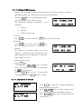
SAFETY INSTRUCTIONS
Safety Instructions for the Operator
WARNING
Do not open the equipment except to
replace paper.
Only qualified personnel should work
inside the equipment.
Immediately turn off the power at the
switchboard if water leaks into the
equipment or something is dropped
into the equipment.
WARNING
Use the proper fuse.
Use of a wrong fuse can result in damage
to the equipment or cause fire.
Handle the LCD with great care. Strong
shock may break it.
Continued use of the equipment can cause
fire or electrical shock. Contact a FURUNO
agent for service.
If the LCD breaks, LCD liquid may leak out.
Do not swallow or touch the liquid - it is
toxic if swallowed. If it is swallowed or
contacts eyes, rinse the contacted area
thoroughly with water and contact a
physician immediately.
Do not disassemble or modify the
equipment.
Dispose of the main unit according to
appropriate regulations.
Fire, electrical shock or serious injury can
result.
The main unit contains a battery. It should
also be disposed of according to
appropriate regulations.
Do not place liquid-filled containers on
the top of the equipment.
Fire or electrical shock can result if a liquid
spills into the equipment.
The power supply shall conform to
the recommended rating.
Fire or electrical shock may result if an
improper power supply is used.
Immediately turn off the power at the
switchboard if the equipment is emitting
smoke or fire.
Continued use of the equipment can cause
fire or electrical shock. Contact a FURUNO
agent for service.
Make sure no rain or water splash leaks
into the equipment.
Fire or electrical shock can result if water
leaks in the equipment.
CAUTION
Do not use commercial cleaners to
clean the main unit.
Commercial cleaners may remove paint
and markings. Remove dust from the main
unit with a soft cloth. For stubborn dirt, use
water-diluted mild detergent and a soft
cloth.
Be careful not to catch fingers between
upper lid and chassis when changing
recording paper.
Injury may result.
Safety Instructions for the Operator (con't)
WARNING LABEL
A warning label is attached to the main unit.
Do not remove the label. If the label is missing or
damaged, contact a FURUNO agent or dealer
about replacement.
WARNING
To avoid electrical shock, do not
remove cover. No user-serviceable
parts inside.
Name:
Warning Label 1
Type:
86-003-1011-1
Code No.: 100-236-231
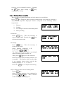
Safety Instructions for the Installer
CAUTION
WARNING
Securely attach protective
earth to the ship's body.
Observe the following compass safe
distances to prevent interference to a
compass:
The protective earth is required
to the power supply to prevent
electrical shock.
Main unit
Magnetic
compass
Steering
compass
1.0 m
0.7 m
Do not install the main unit in direct
sunlight or where it may be subjected
to vibration or shock.
Inappropriate mounting location may affect
performance or damage the unit.
CONTENTS
Page
1. OUTLINE
1.1
1.2
1.3
・・・・・ ・・・・・・・・・・・・・・・・・・・・・・・・・・・・・・・・
1
Characteristics ・・・・・・・・・・・・・・・・・・・・・・・・・・・・・
List of Standard Components ・・・・・・・・・・・・・・・・・・・・・
System Components ・・・・・・・・・・・・・・・・・・・・・・・・・・・・
1
2
3
2. OPERATION
2.1
2.2
2.3
Description of key ・・・・・・・・・・・・・・・・・・・・・・・・・・・
Contrast and brightness ・・・・・・・・・・・・・・・・・・・・・・・・
Basic operation ・・・・・・・・・・・・・・・・・・・・・・・・・・・・
4
2.3.1 Channel setting ・・・・・・・・・・・・・・・・・・・・・・・・・・・
2.3.2 Fine-adjustment of frequency,
and selection of a desired frequency ・・・・・・・・・・・・・・
2.3.3 Start and stop of recording ・・・・・・・・・・・・・・・・・・・
2.3.4 Manual phasing ・・・・・・・・・・・・・・・・・・・・・・・・・・・
2.3.5 Synchronization ・・・・・・・・・・・・・・・・・・・・・・・・・・・
2.3.6 Selection of reception mode ・・・・・・・・・・・・・・・・・・・・
2.3.7 Timer release and release of key lock in the timer mode ・・
7
2.4 Description of setting mode
2.4.1
2.4.2
2.4.3
2.4.4
2.4.5
2.4.6
2.4.7
2.4.8
2.4.9
7
7
7
8
8
8
9
9
・・・・・・・・・・・・・・・・・・・・・
10
Switching of receiver (audio) ・・・・・・・・・・・・・・・・・・
Setting of timer reception ・・・・・・・・・・・・・・・・・・・・・
Sleep timer setting ・・・・・・・・・・・・・・・・・・・・・・・・・
Registration of new frequency ・・・・・・・・・・・・・・・・・・・
Time setting ・・・・・・・・・・・・・・・・・・・・・・・・・・・・・
Setting of ISB frequency ・・・・・・・・・・・・・・・・・・・・・・
Adjustment of contrast ・・・・・・・・・・・・・・・・・・・・・・・
RAM clearance function ・・・・・・・・・・・・・・・・・・・・・・・
Attention at the time of operation ・・・・・・・・・・・・・・・・
10
11
12
13
14
15
15
16
16
2.5 Operation with external receiver
・・・・・・・・・・・・・・・・・・
17
Back-up battery ・・・・・・・・・・・・・・・・・・・・・・・・・・・・
Lubrication and Cleaning ・・・・・・・・・・・・・・・・・・・・・・・
18
3. MAINTENANCE
3.1
3.2
18
4. INSTALLATION
4.1
4.2
4.3
4.4
4.5
Main unit ・・・・・・・・・・・・・・・・・・・・・・・・・・・・・・・・・
Wiring ・・・・・・・・・・・・・・・・ ・・・・・・・・・・・・・・・・・・・
4.2.1 DC power supply built-in type ・・・・・・・・・・・・・・・
4.2.2 AC power supply built-in type ・・・・・・・・・・・・・・・
Terminal board ・・・・・・・・・・・・・・・・・・・・・・・・・・・・・
4.3.1 Connection of BK ・・・・・・・・・・・・・・・・・・・・・・・・
4.3.2 Connection with external receiver ・・・・・・・・・・・・・
Grounding ・・・・・・・・・・・・・・・・・・・・・・・・・・・・・・・・
Receiving antenna ・・・・・・・・・・・・・・・・・・・・・・・・・・・
i
19
20
20
20
21
21
21
22
22
4.6
Exchange of a recording paper
5. SPECIFICATIONS
5.1
5.2
5.3
5.4
・・・・・・・・・・・・・・・・・・・
23
・・・・・・・・・・・・・・・・・・・・・・・・・・・・・・・・ SP-1
Receiver ・・・・・・・・・・・・・・・・・・・・・・・・・・・・・・・・・・ SP-1
Recorder ・・・・・・・・・・・・・・・・・・・・・・・・・・・・・・・・・ SP-1
Automatic Control ・・・・・・・・・・・・・・・・・・・・・・・・・・・・ SP-1
Power, Dimension & Weight ・・・・・・・・・・・・・・・・・・・・・・ SP-1
APPENDIX
TABLE OF FACSIMILLE STATION
Area map of existing stations ・・・・・・・・・・・・・・・・・・・・・・ SP-2
Facsimile station table ・・・・・・・・・・・・・・・・・・・・・・・・・・ SP-3
PACKING LIST
・・・・・・・・・・・・・・・・・・・・・・・・・・・・・・・・・ A-1~2
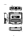
Outside view
・・・・・・・・・・・・・・・・・・・・・・・・・・・・・・・・・・・D-1
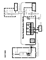
Layout diagram
・・・・・・・・・・・・・・・・・・・・・・・・・・・・・・・・・ D-2
ii
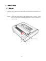
1.OUT LINE
FAX-410 is the high sensitive weather facsimile receiver using electronic scanning
thermal head recording system.
1.1 Characteristics
(1) Electronic scanning with thermal head recording system provides clear image, quiet
operation.
(2) Pre-programmed all existing weather facsimile stations in the world.
Vacant
channels for new station are provided, and rewriting of the memory data is possible
for changing frequency of existing station.
(3) 9-tones gradation recording function provides clear and detailed weather photo from
satellite.
(4) Timer programming function up to 16 programs in a week provides operation free
for reception of each program.
(5) ISB shift function is equipped for corresponding to simultaneous broadcasting of
fax/teletype by a multiple method of SSB by the station of the U.S. Marines
management to which the frequency irregularly changes by 1-2kHz.
(6) Possible to record the data receiving signal from external receiver.
(7) Automatic start/stop circuit is equipped in accordance with WMO standard.
(8) Easy operation by automatic selection of phase matching and recording speed.
1
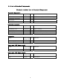
1.2 List of Standard Components
Facsimile receiver. List of Standard Components
Standard Components
Name
Main unit
Installation materials
Accessories
Spare parts
Installation materials
Name
Grounding wire
Coaxial connector
Self-tapping screw
Flat washer
Accessories
Name
Recording paper
Model nam
e/Code No.
Q’ty
Remarks
FAX-410
1 set
1
1 set
1 set
AC Power supply or DC Power supply
Model nam
e/Code No.
Q’ty
Remarks
343200G01
2m
2
4
5
With terminal
Q’ty
Remarks
M207-P
M5×25
M6
Model nam
e/Code No.
1
1
F220VP
Operator’s Manual
Spare parts(AC Power supply)
Name
Model nam
e/Code No.
Fuse
4
ST4-2AN1
Spare parts(DC Power supply)
Name
Model nam
e/Code No.
Fuse
Q’ty
Q’ty
4
ST6-7A
2
For Antenna cable
Clamp for Main unit
Adjust to Clamp for Main unit
257mm×30m
Remarks
250VAC2A
Remarks
125VAC7A
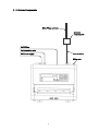
1.3 System Components
2.6m Whip antenna
Antenna
coupler,fax-5
To BK line
To Grounding wire
To Power supply
Coaxial cable
Main unit
3
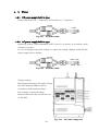
2.OPERATION
The unit, with antenna(s) and power supply, receives and records signal automatically
by the control of APSS when desired channels have been set.
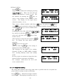
2.1 Description of key
Program key
PRG
: For preparation to mode setting.
One of following modes can be selected by pressing
PRG
key and next, a
N
0~9
key.
Be sure to follow instruction of the indicator in
selecting a mode.
To cancel a setting, press the PRG
key to reset to the initial display of selection mode.
Then, press a
N
0~9
key to reset or the
C
key
to set the standard operation mode.
: Switch the receiver, internal or external
1
1
key
2
2
key
3
3
key
: Set sleep timer
4
4
key
: Set a new frequency or change stored frequency
5
5
key
6
6
key
9
9
key
: Set timer reception
: Set clock time
: Set ISB
: Clear RAM
DIM
SPD
Dimmer key
: For adjusting a backlight brightness of the LCD
indicator, 4 levels selectable.
Speed key
: For selection of SPD (speed).
-4-
IOC
2
4
IOC key
: For selection of IOC.
Up key
: Channel up in the channel mode or frequency up in
the frequency mode.
Left key
: For manual phasing in recording (towards left).
A press of the key shifts 2.5% of the paper width.
6
Right key
: For manual phasing in recording (towards right).
A press of the key shifts 2.5% of the paper width.
8
Down key
: Channel down in the channel mode or frequency
down in the frequency mode.
REV
・
FRQ
Reverse key
or dot key
: (REV) For reversal of black-white of the recording.
( ) Decimal point in setting time or frequency.
A press of the key alternates the (REV)/( ).
.
.
Frequency key : For selection of frequency mode from channel mode
and for shift to frequency setting in the frequency
mode.
For frequency setting, press FRQ key and
enter frequency with
N
0~9
keys and
REV
・
key.
(unit: 0.1kHz, Available frequency for setting are
within 80-159.9kHz or 2-24.9999MHz.)
-5-
CH
Channel key
: For selection of
channel mode from frequency
mode, and for shift to the channel setting in the
channel mode. For setting a channel,
press
three
CH
N
0~9
key and enter channel number with
keys.
The channel covers 000~406 (existent frequency)
and 410~733 (new frequency).
C
Clear key
: For deletion of memorized value in a set mode and
for return to the standard operation mode from a
set mode.
RCD
Record key
: To start and stop recording.
mode, a press of
In the non-recording
RCD key sets automatic phasing
mode and recording starts when phasing is
completed.
In the automatic phasing, a press of
RCD key stops the automatic phasing and starts
recording.
A press of
RCD key while recording
stops recording.
5
N
0~9
E
○ key
: Time display (clock function)
Number key
: To enter number or mode.
Entry key
: To acknowledge setting.
-6-
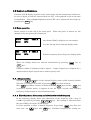
2.2 Contrast and brightness
Contrast of LCD display depends on the visual angle and the temperature and hence,
be sure to adjust it with the contrast knob (see Fig. 1) for optimum result at the time
of installation.
pressing the
The backlight brightness of the LDC can be adjusted in five stages by
key.
DIM
2.3 Basic operation
Power switch is on the left of the front panel.
When the power is turned on, the
channel at the last power off is displayed.
C000
S120
JMH
I576
3622.5
The channel [000] is displayed as an example.
C on the left top shows channel display mode.
000
S120
JMH F 3622.5
I576
F before frequency shows frequency display mode.
These two display modes are selected alternatively by pressing
CH
FRQ
key or
key.
Channel number is displayed with 3 figures.
Upper 2 figures are assigned for a
station and last figure represents its own frequency code.
2.3.1 Channel setting
A press of
▽ key in the channel display mode scrolls channel number.
Selection of a channel is possible by pressing REV
・ key first and next,
N
N
three 0~9 keys.When a station is chosen with two CH keys and the 0~9
key
△
is pressed, asterisk mark (*) appears in the 3rd figure and the most sensitive
frequency of that station is selected automatically.
2.3.2 Fine-adjustment of frequency, and selection of a desired frequency
In the frequency display mode, fine-adjustment of the frequency with a step of
0.1kHz is possible by pressing
△
▽
the green LED is lit on the TUNE display.
key.
Best tuning is indicated when
It is also possible to select a desired frequency by pressing
next, four~six
N
0~9
keys with
REV
-7-
・
FRQ
key first and
key (available frequency for setting are
within 2000.0~24999.9kHz).
2.3.3 Start and stop of recording
(1) Start
Recording starts automatically (Start/Stop, Phase, Speed, IOC) by receiving the
APSS signal.
To start halfway of the received picture, press RCD key once
and automatic speed setting and auto-phasing mode are set. Then, recording
starts upon phasing is completed.
When the phase signal for automatic start is
not received, recording does not start.
Then, press
RCD key again for manual
recording.
(2) Stop
Recording stops automatically when auto stop signal is received.
of auto stop signal or to stop halfway, press
In the absence
RCD key.
2.3.4 Manual phasing
In manual recording mode or when the phasing is not completed in the proper
position by auto phasing,
be sure to adjust the phase using the
key.
The phase signal shifts by 2.5% of the paper width or about 6.4mm per keying.
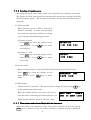
2.3.5 Synchronization
When a recorded picture (phase signal, etc.) drifts to left or right, be sure to adjust
the synchronization with SYNC knob to stop drift.
Turn counter-
SYNC
Turn
clockwise
clockwise
②
①
When the picture is such as shown in the left illustration ( ① ), turn the knob
counter-clockwise.
In case of the right illustration (②), turn the knob clockwise.
-8-
2.3.6 Selection of reception mode
The reception mode refers IOC, speed, and normal/reverse printing and modes.
The former two (IOC and speed) are automatically selected by receiving the APSS
signal and phase signal.
For the latter two modes, desired ones should be selected
manually.
(1) Speed and IOC
When incorrect speed or IOC is selected in
manual recording or when auto-recording
has started at improper position, its setting
can be changed with following procedure.
a) Change of speed
Press SPD key, then the display on the
N
right appears. Press 0~9
key to select
SPEED:120
1-120 2-90
3-60
correct speed.
b) Change of
IOC
Press IOC key, then the display on the
N
right appears. Press 0~9
key to select
IOC:576
1-576 2-288
correct IOC.
(2) Reverse mode
When recorded picture is reversed (white/black), follow the procedure below.
Press
REV
key, then the display on the
・
N
right appears. Press 0~9
key to select
REVERSE: OFF
1-OFF 2-ON
mode.
(3) Time display
A built-in clock is provided.
The present time is displayed by pressing
5
key
in the standard operation mode.
When the displayed time is not correct, be sure to
reset the time by following the instructions in 1.4.5.
C000 JMH
3622.5
APR 10 MON 12:00
Right display indicates April 10, Tuesday, 12:00.
2.3.7 Timer release and release of keylock in the timer mode
When the timer is in operation (except sleep timer), function of each key (except
DIM
key) is locked to keep set values and hence, ordinary keying is inhibited.
-9-
To release this timer or keylock in the timer mode, follow the procedure below.
(1) In the timer standby mode (time for the next recording is displayed):
Press PRG key then the message on the
TIMER RCV : OFF ?
PUSH E KEY
right is displayed. Then,
a press of
E
key releases the timer
operation and shifts the mode to the
standard operation mode.
C
By pressing
key before fix the timer release, the
timer standby mode is maintained.
(2) In the timer operation mode (standard operation being displayed):
Press the PRG key and the message on theright
appears.
Fixing with the
E
key releases the
keylock (even though in the timer operation mode,
KEY LOCK : OFF ?
PUSH E KEY
each key function is revised and all operations
are possible).
To release the timer mode in such a case, refer to 1.4.2.
displayed, it is possible to clear the keylock off with the
When the keylock off is
C
key.
2.4 Description of setting mode
Shift to a set mode is made by pressing the
PRG key. When the mode is set, the
message on the right is shown. Pressing the
C
key in this mode, the standard
operation mode is reset.
N
0~9
When a
key is pressed, it is possible to
set one of the following modes as explained in
1.4.1~1.4.6.
SET PRG. NO. 1-9
ESC PUSH C KEY
To cancel a setting after shifting to the setting
mode and before fix it, press the PRG key.
Pressing the
PRG key resets to the initial
setting mode (as displayed above).
2.4.1 Switching of receiver (audio)
Switching of the internal or external receiver is set by the following procedure.
Press
1
key.
Then the receiver switching
mode is set and message on the right appears.
The displayed number 1 is for internal
- 10 -
AF
IN : INT
1-INT
2-EXT
receiver, 2 is for external receiver.
the
key after setting a
E
Pressing
N
0~9
key,
completes the setting.
2.4.2 Setting of timer reception
This unit has 16 booking functions and each timer is set as follows.
Press
key. Then the timer reception setting mode is set and the message is
2
shown on the right.The displayed number correspond to the following entries
respectively.
TIMER RCV : 1-OFF
2-ON
3-RCL 4-STR
1 : Release
2 : Setting
3 : Re-calling (readout of the booking data)
4 : Entry booking
(1) Release
Press
key.
1
Then the message is
shown on the right. Pressing the
E
key
releases the timer mode
TIMER RCV : OFF?
PUSH E KEY
(2) Setting
Press
key.
2
Then the message is
shown on the right.
Select
booking
number(s),
0~F,
SET REG No. 0-F
PUSH / & &E KEY
by pressing
△
▽ key.
The display shown on the right is an example
when selecting booking number “0”.
Then, press
key to fix the selection
Plural selection of the booking numbers are
acceptable.
TIMER
0123
RCV
NO.: 4
The display shown on the right
is an example when select and fix the
booking number “0”, “1”, “2” and “3”.
Press the
E
key to complete the setting.
(3) Re-calling (readout of the booking data)
Press
3
key.
Select a booking number to be confirmed by
pressing
△
▽ key.
Then, contents
of the booking data is displayed.
- 11 -
RECALL TIMER REG
SET REG NO. 0- F
(4) Entry booking
Press
key.
4
Select a timer number for booking by pressing
▽ key. Then, the unit will ask
whether the number is correct or not. Fix
STORE
TIMER REG
SET REG NO. 0- F
△
the number by pressing the
E
key or
R1 SET
CHANNEL
NO. in 3 FIGURES
enter a new number if the number is not
correct.
The display on the right shows
when the number 1 is set.
Then, enter a channel number with three
and
REV
・
with the
the
C
keys (or press two
N
0~9
keys
key for automatic setting of the maximum sensitive frequency) and fix
E
key or reset a channel with
key.
Further, set a day of the week with
key and fix it with the
start and end time with
△
▽
key. Then, set
E
N
0~9
R1 C000 SET DAY
of THE WEEK by△ ▽
keys from
00:00 to 23:59.
After setting is competed, fix it with the
key.
N
0~9
E
R1 C000 MON
SET START/ STOP
To change the time while setting,
press the
C
key to reset the time.
After fix with the
E
key, the setting is
displayed as shown on the right.
The message on the right is for setting:
08: 00
PUSH
-
E
09: 00?
KEY
Channel No.000 at JMH 3MHz, booking
No.1, starting Monday 08:00 and ending
09:00.
Be sure to give one minute or longer for time
interval between start times of booking.
000
JMH
3622.5
1MON 08:00- 09:00
For example, 12:00~12:30 for No.1 and
12:31~13:00 for No.2.
2.4.3 Sleep timer setting
The sleep timer indicates the sleep mode after a specified time for reception has
passed and its setting is made as following.
Press
3
on the right.
key.
Then the message is shown
The displayed numbers refer to
- 12 -
the following operations.
SLEEP MODE : OFF
1-OFF 2-ON
1 : Release
2 : Setting
(1) Release
Select “1” in the above message, and fix with
key.
E
SLEEP MODE : OFF ?
PUSH E KEY
(display on the right)
Note: When the system is in the sleep mode,
press
PRG
&
keys to shift
E
the mode to the standard operation
mode.
(2) Setting
Select “2” in the above message, and enter
desired time to sleep by
N
0~9
23:59), and fix it with
E
SLEEP TIME :
SET SLEEP TIME
key (max.
key.
To
correct or change the entered time before
pressing
key, press the
E
for resetting.
C
key
2.4.4 Registration of new frequency
Registration of a new frequency (450~724) or re-writing of an existent frequency
(CH000~443) can be made in the following procedure.
Press the
key, and the frequency
5
registration mode is set.
Then, message
shown on the right appears.
Enter a channel
N
0~9
number with three
keys.
Right example is for channel 000.
To change
the entered number, use the
key. Then,
C
enter a call sign with the
the
the
△
CHANNEL PROGRAM
SET CH in 3 FIGS
C000 SET
IGN by
CALL S-
KEY
&
key, and fix it with
▽
key.
E
To correct call sign, press
C
key and
C000 AAA 0.0
SET FREQUENCY
re-enter a call sign before pressing
key.
E
The message on the right shows when AAA (3 figures) is entered.
Then, enter a frequency (3~6 figures) with
N
0~9
・ key with a unit
of 0.1kHz Available frequency for setting are within 80.0~159.9kHz or 2000.0~
24999.9kHz.
Press
halfway, use
C
E
keys and
key to fix the registration.
key for resetting.
decoder can besetin sequence.
- 13 -
REV
To correct the entry
Further, the speed, IOC, reverse and
SET SPEED
1-120
2-90
120-60
SET REVERSE
3-60
1-0FF
2-ON
SET IOC 576/288
1-576
2-288
2.4.5 Time setting
Clock time can be set by the following procedure.
Pressing the
5
key sets the time
setting mode and message shown on the
right appears.
Set month with
with
E
△
▽
key, and fix it
key.
The message on the right shows entering
April.
the
N
0~9
key, and fix it with the
Then, enter day of the week with
key, and fix it with the
E
key.
APR
SET DATE in 2FIG
E
key.
THE
SET
WEEK
C
To correct the setting halfway, press the
by
APR
10
SET
YEAR
in
2FIG
MON
SET
TIME
in
4FIG
’
key.
E
APR
10
MON ‘05
12:00
- 14 -
DAY
Message
(hour: 2 figures, minute: 2 figures) each with
key for resetting.
10
▽
Finally, enter year (last two figures) and time
key, and fix with the
APR
Of
△
shown on the right indicates Monday.
N
0~9
by / KEY
Next, enter date with 2 figures by
(e.g. April 10th)
the
SET MONTH
2.4.6 Setting of ISB frequency
Signals from multiplex-communication station are easily received by setting an
ISB (Independent side band) width as shown in the following.
Pressing
key sets the ISB setting mode
6
ISB +0.0KHz:OFF
and the message on the right is shown.
The displayed numbers correspond to the
1-OFF 2-ON 3-QTY
following.
1 : Release
2 : Setting
3 : Shift quantity entry
(1) Release
Press
1
key, and fix with the
E
key orelease the mode.
key, and fix with the
E
key,
(2) Setting
Press
2
then a displayed amount of frequency is
ISB +1.9kHz:ON
shifted.
PUSH ENT KEY
Be careful as a frequency shift is set in all
channels. When the power is turned on, the
shift frequency for all channels is indicated
when ISB has been set.
(3) Shift quantity entry
Press
3
key.
Then use the
key to decide
SET
plus (+) or minus (-), and enter a shift width
by
N
0~9
Press the
+/-
key (2 figures).
E
key to fix it.
entry halfway, use the
C
ISB
by
in
・
2FIGS
KEY
To correct the
key for re-entry.
2.4.7 Adjustment of contrast
SET CONTRAST
by △ / ▽ KEY
Press
key, then the contrast adjustment
display appears (upper left).
Press
CONTRAST : 9
By △ / ▽ KEY
7
△
▽
key to select contrast level
for 0 ~ 9. Larger value leads higher contrast.
C key to set and memorize the
E
Press
contrast level.
- 15 -
2.4.8 RAM clearance function
The unit has RAM to memorize the frequency data of the FAX transmitting
stations in the world and to retrieve such data.
Therefore, when a part or all of
RAM data is deleted in error so that the initial data in ROM (data at the time of
delivery) has to be retrieved, the following procedure is needed to clear the RAM
data.
Be careful since all the data in the RAM will be initialized, deleting the
data of registered frequencies, etc. when this procedure is performed.
Pressing
9
key sets the RAM clear mode
and pressing
key clears the RAM data.
E
To stop this procedure, press the
key
C
or the PRG key.
RAM CLEAR!!
PUSH ENT KEY
2.4.9 Attention at the time of operation
Be careful of the following thing when operation.
[CAUTION]
If operations other than normal operation are repeated, the keyboard may lock.
In such a case, turn the power switch OFF, and turn it ON again.
- 16 -
2.5 Operation with external receiver
(1) External receiver
When an external receiver is used, it should have a local oscillator with very good
frequency stability.
The A1 detected beat, a low-frequency output, can be
monitored with the unit when the signal is supplied through receiver jack of the
external receiver.
If the signal is supplied from the speaker terminal, it is
suggested to use a dummy resistor and supply signal from both ends of the dummy
resistor.
The signal enters the input terminal (EXT-IN) on the back of the unit
and should be 50mV or larger at the input terminal.
When an external receiver is
of ordinary type, there will be no problem of excessive input since there is a
protection circuit inside the unit.
However, if direct current is superposed, be
sure to input it through a non-polarized capacitor of about 1μF.
(2) Operation
a) Beat adjustment
When using an external receiver whose beat frequency is adjustable within a
range of ±2kHz or more by means of the beat knob, set the frequency dial so as
to maximize the deflection of the receiver’s “S” meter, and adjust the beat knob
so that the center LED of the tuning indicator of the unit is lit.
When a signal
from station with ISB communication from a U.S. Navy station, e.g., Guam,
Pearl Harbor or San Francisco, is received, sometimes an adjustment of the
frequency is necessary with a variable condenser or spread variable condenser,
because the frequency may shift within a range of ±2kHz from the specified
frequency of the station.
b) Band width
When noise is low, a wide bandwidth is advantageous to have good picture
quality.
However, a narrow bandwidth down to 1kHz is preferable in a noisy
condition.
c) Selection of external receiver
Refer to 1.4.1 to use an external receiver and also to return to the internal
receiver.
d) Recording
Refer to 1.3.3 for recording operations and for reverse reception. In reverse
reception, set the external receiver to the FBO, LSB or USB mode similarly.
NOTE
BFO : Beat frequency oscillator
LSB
:
Lower side band
USB : Upper side band
ISB
:
Independent side band
- 17 -
3. Maintenance
3.1 Back-up battery
This device uses a manganese lithium battery as a back-up battery.
Please exchange to new one after using for 5 years.
Ask to a service shop for replacing the back-up battery.
3.2 Lubrication and Cleaning
(1) Lubrication
Lubricate a paper sending gear with 1-2 drops of lubricating oil at every 2-3
months.
(2) Cleaning
Clean the thermal head with attached cotton cleaner at every month.
When garbage has adhered to the thermal head, soak a little ethyl alcohol on
cloth and wipe it off. Don't use other than ethyl alcohol.
- 18 -
4.INSTALLATION
4.1Main unit
Install the TF-711 main unit on a plane desk or a solid and plane wall with 4 pcs. of
screws and washers.
Caution: A print may become blurred if the installation place is uneven.
In that
case, put some washers or suitable attachment to adjust the flatness as
following figure.
Blurred part
Washer
- 19 -
4.2
4.2.1
Wiring
DC power supply built-in type
Connect black wire to “-“ (negative), and red wire to “+” (positive).
7A fuse
+ : Red
- : Black
Fig. 4.2.1
4.2.2
DC power cable
AC power supply built-in type
Operation voltage (100/115/200/230 VAC) is pre-set at factory in accordance with
customer’s request.
In case of changing operation voltage, re-adjust the voltage changer inside the AC
power supply unit as follows.
2A fuse
HOT : Gray
COLD : Gray
Fig. 4.2.2
AC power cable
Voltage setting:
Referring to drawing in the right, change
the short harness (ribbon wire) in
accordance with required voltage.
For example, connect the short
Harness Between CN4 and CN5 in case
of 100 VAC.
- 20 -
Fig. 4.2.3
AC power supply unit
4.3 Terminal board
Use terminal board on the rear panel of
the main unit for the connection between
BK, external receiver or decoder.
Insert a
connection wire in a terminal in the following ways.
Push knob
Press a push knob by
a screwdriver
Peel off vinyl sheath
of the wire about 10mm
Terminal board
Connection
wire
Wire hole
Insert a connection wire to a hole
while pressing the push knob
Note: Use connection wire with single core 0.4~1.0mmØ or standard twist
core 0.3mm2~0.7mm2.
4.3.1 Connection of BK
Connect BK referring to attached “Layout diagram” in the APPENDIX.
BK voltage is 12 ~ 24 VDC, no polarity.
BK cable is not included in the standard supply scope.
4.3.2 Connection with external receiver
Connect with external receiver referring to article 2.5 “Operation with external
receiver” (page 17).
- 21 -
4.4 Grounding
A GND terminal is on the rear panel of the main unit.
Be sure to ground the main unit using attached earth wire (3m KIV wire 50/0.45 with
copper tube terminal).
4.5 Receiving antenna
Following antennas are suitable to use as the receiving antenna for the FAX-410.
A) Antenna coupler FAX-5 + 2.6 m whip antenna (supplied by us as option)
B) Whip antenna (6 m ~ 8 m)
C) Wire antenna (Reverse-L or T type)
Note: Generally, whip antenna is suitable for reception over 6 MHz, and wire antenna is
suitable for reception under 6 MHz.
Receiving sensitivity would become worse when using one antenna for other receivers
and/or transmitters through multi-coupler. In that case, please use other antenna or
install exclusive antenna.
Be sure to connect BK especially for following case in order to avoid from burning trouble
of antenna coil/receiver circuit.
A) In case of using same antenna which is used for a transmitter
B) When a transmitting antenna is located near to receiving antenna of FAX-410
Use high frequency coaxial cable as an antenna cable.
When using optional antenna coupler FAX-5, turn ON the switch S1 on BK board inside
the main unit.
- 22 -
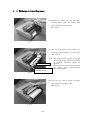
4.6 Exchange of a recording paper
(1) Remove the front cover, up the paper
①
cutting plate, slide the paper feed
lever in the direction of rear.
(Ref. Fig.1)
Fig.1
(2) Set the roll paper to the holder by
pressing a paper guide ② to left side.
(Ref. Fig.2)
Press
Note: The paper guide ② can be moved
about 3cm to left, and can be locked
by rotating clockwise (about 90
Paper guide ②
degree).
The lock can be released by rotating
the paper guide anti-clockwise
Spring (between paper
(about 90 degree).
guide and chassis)
Fig.2
(3) Pull out the end of paper upwards
from under the rubber roller.
(Ref. Fig.3)
Fig.3
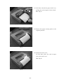
- 23 -
Fig.3
(4) Pull down ahead the paper feed lever,
③
pulling the end of paper a little ahead.
(Ref. Fig.4)
Fig.4
(5) Return the paper cutting plate to the
original position.
Fig.5
(6) Install the front cover.
At that time, place the end of paper
above the front cover.
(Ref. Fig.6)
Fig.6
- 24 -
5.SPECIFICATIONS
5.1 Receiver
Reception
: Synthesized double superheterodyne
Frequency range
: MF/HF 2.0000 ~ 24.99999 MHz
Mode
: F3C
Selectivity
: 2.0 kHz at –6 dB
Number of channels : 315 channels
Sensitivity
: MF/HF 2µV at 20 dB SINAD
Channel selection
: Automatic or manual, digital with ten-key pad
Tuning indicator
: 3 LEDs (light emitting diodes)
Display
: 32 characters in 2 lines with LCDs (liquid crystal display)
Audio input
: Impedance 600Ω, frequency 1900 ± 400 Hz level 0 dBm,
or high impedance
5.2 Recorder
Recording system
: Electronic scanning with thermal head
IOC
: Index of cooperation – 576 and 288
Recording speed
: 60, 90, 120 scans per minute
Gradation
: 9 tones (white, 7 gray levels and black)
Recording paper
: Thermal paper (257 mm X 60 m)
Line density
: 8 dots/mm (total number of dots: 2048)
5.3 Automatic Control
Start/stop
: Automatic start or stop by timer program and/or WMO
standard
remote control signal (or manual)
Recording rate
: Automatic selection of recording rate (or manual)
IOC
: Automatic selection of IOC by WMO start signal (or manual)
Phase
: Automatic selection of phase matching by passing signal
(or manual)
5.4 Power, Dimension & Weight
Power source
: DC 10 ~ 40 V,
max. 28 W
AC 100/115/200/230V, 50 or 60 Hz, max. 30 VA
Dimension
: 93(H) - 382(W) - 312.5(D) mm
Weight
: 7.4 kg ± 0.7 kg (AC type, including recording paper)
6.9 kg ± 0.7 kg (DC type, including recording paper)
SP - 1
TABLE OF FACSIMILE STATION
Table of pre-programmed frequencies and area map
This unit has a ROM (read only memory) which is pre-programmed 150 of
existing frequencies of transmitting stations.
Stations and frequencies are shown
in the map and table respectively.
This table is reference data and is subject to change without previous notice.
Area map of sxisting stations
RBW
VFA
VFF
GYA
■
AOK
OXT
DDK
SVJ
IMB
RCC
NOJ
RBV
RBX
ATP
CKN
BAF
3SD ■ HLL JMH
BDF
■
■JFC
BMF ■
JJC
NMC
OXT
CFH
NMF
■
■
NMG
KVM
HSW
6VU
VCO
■
5YE
ZSJ
VMW
PWZ
VMC
CBV
ZKLF
SP - 2
LOR
SP - 2
JJC
JJC
JJC
JJC
JFC
011
012
013
014
015
020
BAF
BAF
BAF
BAF
BAF
BAF
042
043
044
045
HLL
034
041
HLL
033
040
HLL
HLL
030
032
HLL
024
031
JFC
JFC
023
JFC
JJC
010
JFC
JJC
002
022
JMH
001
021
JMH
JMH
000
CALL SIGN
CHANNEL NO.
BEIJING
BEIJING
BEIJING
BEIJING
BEIJING
BEIJING
SEOUL
SEOUL
SEOUL
SEOUL
SEOUL
JAPAN
JAPAN
JAPAN
JAPAN
JAPAN
MALAYSIA
MALAYSIA
MALAYSIA
MALAYSIA
MALAYSIA
MALAYSIA
JAPAN
JAPAN
JAPAN
STATION
18236.9
16025.9
14366.9
10116.9
8121.9
5526.9
13570.0
9165.0
7433.5
5857.5
5385.0
16907.5
13074.0
8658.0
6414.5
4274.0
17430.0
22542.0
17069.6
16971.0
12745.5
8467.5
13597.0
7305.0
3622.5
[kHz]
FREQUENCY
SP - 3
094
093
092
091
090
084
083
082
081
080
074
073
072
071
070
064
063
062
061
060
052
051
050
CHANNEL NO.
VMC
VMC
VMC
VMC
VMC
ZKLF
ZKLF
ZKLF
ZKLF
ZKLF
BMF
BMF
BMF
BMF
BMF
BDF
BDF
BDF
BDF
BDF
3SD
3SD
3SD
CALL SIGN
FACSIMILE STATION TABLE
CHARLEVILLE
CHARLEVILLE
CHARLEVILLE
CHARLEVILLE
CHARLEVILLE
AUCKLAND
AUCKLAND
AUCKLAND
AUCKLAND
AUCKLAND
TAIPAI
TAIPAI
TAIPAI
TAIPAI
TAIPAI
SHANGHAI
SHANGHAI
SHANGHAI
SHANGHAI
SHANGHAI
BEIJING
BEIJING
BEIJING
STATION
20469.0
13920.0
11030.0
5100.0
2628.0
16340.1
13550.5
9459.0
5807.0
3247.4
18560.0
13900.0
8140.0
5250.0
4616.0
18940.0
11420.0
7420.0
5100.0
3241.0
16903.9
12831.9
8461.9
[kHz]
FREQUENCY
CALL SIGN
V MW
V MW
V MW
V MW
V MW
V LM
KV M
KV M
KV M
KV M
HSW
HSW
ATP
ATP
GYA
GYA
GYA
GYA
5YE
5YE
ZSJ
ZSJ
ZSJ
ZSJ
CHANNEL NO.
100
101
102
103
104
110
120
121
122
123
130
131
140
141
150
151
152
153
160
161
170
171
172
173
CAPE NAV AL
CAPE NAV AL
CAPE NAV AL
CAPE NAV AL
NAIROBI
NAIROBI
PERSIAN GULF
PERSIAN GULF
PERSIAN GULF
PERSIAN GULF
NEW DELHI
NEW DELHI
BANGKOK
BANGKOK
HONOLULU
HONOLULU
HONOLULU
HONOLULU
CASEY
WILUNA
WILUNA
WILUNA
WILUNA
WILUNA
STATION
18238.0
13538.0
7508.0
4014.0
17447.5
9044.9
18261.0
14436.0
6834.0
3289.5
14842.0
7404.9
17520.0
7396.8
23331.5
16135.0
11090.0
9982.5
7470.0
18060.0
15615.0
10555.0
7535.0
5755.0
[kHz]
FREQUENCY
SP - 4
NMG
CFH
CFH
243
CFH
242
CFH
NMF
NMF
NMF
NMF
NMG
241
240
233
232
231
230
223
NMG
221
222
NMG
CBV
220
CBV
212
CBV
PWZ
211
210
201
PWZ
LOR
191
200
LOR
6V U
6V U
6V U
CALL SIGN
190
182
181
180
CHANNEL NO.
HALIFAX
HALIFAX
HALIFAX
HALIFAX
BOSTON
BOSTON
BOSTON
BOSTON
NEW ORLEANS
NEW ORLEANS
NEW ORLEANS
NEW ORLEANS
V ALPARAISO
V ALPARAISO
V ALPARAISO
RIO DE JANEIRO
RIO DE JANEIRO
PUERTO BELGRANO
PUERTO BELGRANO
DAKAR
DAKAR
DAKAR
STATION
13510.0
10536.0
6496.4
4271.0
12750.0
9110.0
6340.5
4235.0
17146.4
12789.9
8503.9
4317.9
17146.4
8677.0
4228.0
16978.0
12665.0
12672.0
5705.0
19750.0
13667.5
4790.5
[kHz]
FREQUENCY
NOJ
NOJ
NMC
NMC
NMC
NMC
NMC
IMB
IMB
IMB
SV J
SV J
302
303
310
311
312
313
314
320
321
322
330
331
ATHENS
ATHENS
ROMA
ROMA
ROMA
PT.REYES
PT.REYES
PT.REYES
PT.REYES
PT.REYES
KODIAK
KODIAK
KODIAK
NOJ
301
AIRBORNE ICE T.
AIRBORNE ICE T.
KODIAK
XL17
282
NOJ
XL17
281
AIRBORNE ICE T.
300
XL17
280
INUV IK
COST GUARD ICE B.
V FA
270
SYDNEY,NOV A SCOTIA
SYDNEY,NOV A SCOTIA
IQALUIT & RESOLUTE
IQALUIT & RESOLUTE
STATION
290
V CO
V CO
V FF
251
261
V FF
250
260
CALL SIGN
CHANNEL NO.
8105.0
4481.0
13597.4
8146.6
4777.5
22527.0
17151.2
12786.0
8682.0
4346.0
12412.5
8459.0
4298.0
2054.0
14770.0
7708.1
6915.1
4616.0
8457.8
6915.0
4416.0
7710.0
3253.0
[kHz]
FREQUENCY
SP - 5
393
OXT
OXT
OXT
391
392
OXT
390
DDK
DDK
382
DDH
381
GYA
GYA
GYA
GYA
RBW
RBW
RBW
380
373
372
371
370
363
362
361
RBW
ROM
354
360
RCH
RIJ
RBX
RBX
353
352
351
350
RBV
345
RBX
RCH
344
343
RPJ
RBV
342
RBV
CALL SIGN
341
340
CHANNEL NO.
SKAMLEBAEK
SKAMLEBAEK
SKAMLEBAEK
SKAMLEBAEK
HAMBURG
HAMBURG
HAMBURG
NORTHWOOD
NORTHWOOD
NORTHWOOD
NORTHWOOD
MURMANSK
MURMANSK
MURMANSK
MURMANSK
TASHKENT2
TASHKENT2
TASHKENT2
TASHKENT2
TASHKENT2
TASHKENT
TASHKENT
TASHKENT
TASHKENT
TASHKENT
TASHKENT
STATION
17510.0
13855.0
9360.0
5850.0
13882.5
7880.0
3855.0
11086.5
8040.0
4610.0
2618.5
10130.0
7908.8
6445.5
5336.0
13947.0
9150.0
8083.0
5285.0
3280.0
14982.5
9340.0
7570.0
5890.0
4365.0
3690.0
[kHz]
FREQUENCY
CALL SIGN
RCC
RCC
RCC
RCC
RCC
RDD
RCC
PRIV
CHANNEL NO.
400
401
402
403
404
405
406
410~733
MOSCOW
MOSCOW
MOSCOW
MOSCOW
MOSCOW
MOSCOW
MOSCOW
STATION
×5
12961.0
11617.0
10980.0
7695.0
6987.0
5008.0
3830.0
[kHz]
FREQUENCY
SP - 6
CHANNEL NO.
CALL SIGN
STATION
[kHz]
FREQUENCY
(#:㧔#%
࡙࠾࠶࠻
70+6
#:: 㧼㧭㧯㧷㧵㧺㧳ޓ㧸㧵㧿㨀
(#:㧔#%
0#/'
੍ຠ
࡙࠾࠶࠻
&'5%4+26+10%1&'ͳ
176.+0'
36;
52#4'2#465
70+6
(#:
㩖㨱㩂㩆㩚㩢ฃ↹ⵝ⟎
(#%5+/+.'4'%'+8'4
ઃዻຠ
੍ຠ
#%%'5514+'5
52#4'2#465
#
▤ࠅ㩕㨷㨺㩇㩨
㧳.#5567$'(75'
Ꮏ᧚ᢱ
ઃዻຠ
+056#..#6+10/#6'4+#.5
#%%'5514+'5
(82
⸥㍳⚕
4'%14&+0)2#2'4
Ꮏ᧚ᢱ
+056#..#6+10/#6'4+#.5
/
㨻㨺㩇✢
)4170&+0)9+4'
/2
หゲ㩖㩩㩡㩂㩨
%1#:2.7)
:575
㩏㩗㩨㩊㨹㩕㩩㩧㩒㩆㩨
5'.(6#22+0)5%4'9
࿑ᦠ
&1%7/'06
/
ᐔᐳ㊄
(.#69#5*'4
࿑ᦠ
&1%7/'06
ขᛒ⺑ᦠ
12'4#6145/#07#.
䋨㪁䋩䈲䇮䍞䍼䍮䍎䍘䍎䍢䍼䈮ઃ䈐䇮ᵈᢥ䈪䈐䉁䈞䉖䇯
䋨㪁䋩䇭㪫㪟㪠㪪㩷㪚㪦㪛㪜㩷㪚㪘㪥㪥㪦㪫㩷㪙㪜㩷㪦㪩㪛㪜㪩㪜㪛㪅
䍘㪄䍢䍼⇟ภᧃየ䈱㪲㪁㪁㪴䈲䇮ㆬᛯຠ䈱ઍ䍘䍎䍢䍼䉕䈚䉁䈜䇯
㪚㪦㪛㪜㩷㪥㪬㪤㪙㪜㪩㩷㪜㪥㪛㪠㪥㪞㩷㪮㪠㪫㪟㩷㩹㪁㪁㩹㩷㪠㪥㪛㪠㪚㪘㪫㪜㪪㩷㪫㪟㪜㩷㪚㪦㪛㪜㩷㪥㪬㪤㪙㪜㪩㩷㪦㪝㩷㪩㪜㪧㪩㪜㪪㪜㪥㪫㪘㪫㪠㪭㪜㩷㪤㪘㪫㪜㪩㪠㪘㪣㪅
㧔⇛࿑ߩኸᴺߪޔෳ⠨୯ߢߔ&ޕ+/'05+105+0&4#9+0)(144'('4'0%'10.;㧕
#::
㧔⇛࿑ߩኸᴺߪޔෳ⠨୯ߢߔ&ޕ+/'05+105+0&4#9+0)(144'('4'0%'10.;㧕
A-1
(#:㧔&%
࡙࠾࠶࠻
70+6
#:: 㧼㧭㧯㧷㧵㧺㧳ޓ㧸㧵㧿㨀
(#:㧔&%
0#/'
࡙࠾࠶࠻
੍ຠ
&'5%4+26+10%1&'ͳ
176.+0'
36;
70+6
52#4'2#465
(#:
㩖㨱㩂㩆㩚㩢ฃ↹ⵝ⟎
(#%5+/+.'4'%'+8'4
੍ຠ
ઃዻຠ
52#4'2#465
#%%'5514+'5
#
▤ࠅ㩕㨷㨺㩇㩨
).#5567$'(75'
ઃዻຠ
Ꮏ᧚ᢱ
#%%'5514+'5
+056#..#6+10/#6'4+#.5
(82
⸥㍳⚕
4'%14&+0)2#2'4
Ꮏ᧚ᢱ
+056#..#6+10/#6'4+#.5
/
㨻㨺㩇✢
)4170&+0)9+4'
/2
หゲ㩖㩩㩡㩂㩨
%1#:2.7)
:575
㩏㩗㩨㩊㨹㩕㩩㩧㩒㩆㩨
5'.(6#22+0)5%4'9
࿑ᦠ
&1%7/'06
/
ᐔᐳ㊄
(.#69#5*'4
࿑ᦠ
&1%7/'06
ขᛒ⺑ᦠ
12'4#6145/#07#.
䋨㪁䋩䈲䇮䍞䍼䍮䍎䍘䍎䍢䍼䈮ઃ䈐䇮ᵈᢥ䈪䈐䉁䈞䉖䇯
䋨㪁䋩䇭㪫㪟㪠㪪㩷㪚㪦㪛㪜㩷㪚㪘㪥㪥㪦㪫㩷㪙㪜㩷㪦㪩㪛㪜㪩㪜㪛㪅
䍘㪄䍢䍼⇟ภᧃየ䈱㪲㪁㪁㪴䈲䇮ㆬᛯຠ䈱ઍ䍘䍎䍢䍼䉕䈚䉁䈜䇯
㪚㪦㪛㪜㩷㪥㪬㪤㪙㪜㪩㩷㪜㪥㪛㪠㪥㪞㩷㪮㪠㪫㪟㩷㩹㪁㪁㩹㩷㪠㪥㪛㪠㪚㪘㪫㪜㪪㩷㪫㪟㪜㩷㪚㪦㪛㪜㩷㪥㪬㪤㪙㪜㪩㩷㪦㪝㩷㪩㪜㪧㪩㪜㪪㪜㪥㪫㪘㪫㪠㪭㪜㩷㪤㪘㪫㪜㪩㪠㪘㪣㪅
㧔⇛࿑ߩኸᴺߪޔෳ⠨୯ߢߔ&ޕ+/'05+105+0&4#9+0)(144'('4'0%'10.;㧕
#::
㧔⇛࿑ߩኸᴺߪޔෳ⠨୯ߢߔ&ޕ+/'05+105+0&4#9+0)(144'('4'0%'10.;㧕
A-2
7C-2V 16m
(5C-2V)
M207-P/
(M205-P)
(M205-P)
M207-P
Turn ON switch S1 on RCV board in the main unit for
using optional active antenna coupler FAX-5.
【Caution】
Grounding
KIVWire
0.3m
Active
antenna
coupler
FAX-5
antenna(2.6m)
Whip
Option
Layout diagram
-
-
D-2
AF OUT
+
+
IN
2
IN
BK
1
EXT
BK
External
receiver
AF
OUT
+ -
Selectable AC or DC
when placing order
7A
FUSE
12-24VDC
FUSE
200 230 VAC 2A
100 115
3m
AC Power
supply unit
Grounding
Weather Facsimile Receiver FAX-410
+
Black -
Red
3m
DC Power
supply unit