1
00809-0100-4263
English
Rev. AA
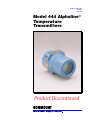
Model 444 Alphaline®
Temperature
Transmitters
Product Discontinued
Product Manual
1
Model 444 Alphaline®
Temperature Transmitters
NOTICE
Read this manual before working with the product. For personal and system
safety, and for optimum product performance, make sure you thoroughly
understand the contents before installing, using, or maintaining this product.
Within the United States, Rosemount Inc. has two toll-free assistance numbers.
Customer Central: 1-800-999-9307 (7:00 a.m. to 7:00 p.m. CST)
Technical support, quoting, and order-related questions.
North American
1-800-654-7768 (24 hours a day – Includes Canada)
Response Center: Equipment service needs.
For equipment service or support needs outside the United States, contact your
local Rosemount representative.
The products described in this document are NOT designed for nuclearqualified applications.
For information on Rosemount nuclear-qualified products, contact your local
Rosemount Sales Representative.
Rosemount, the Rosemount logotype, and Alphaline are registered trademarks of Rosemount Inc.
Chromel and Alumel are trademarks of Hoskins Mfg. Co.
Cover Photo: 444-005AC
Fisher-Rosemount satisfies all obligations coming from legislation
to harmonize product requirements in the European Union.
Rosemount Inc.
8200 Market Boulevard
Chanhassen, MN 55317 USA
Tel 1-800-999-9307
Telex 4310012
Fax (612) 949-7001
PR
ED
INT
IN
U. S. A.
00809-0100-4263
© Rosemount Inc. 1998.
http://www.rosemount.com
SNF-0004
Using non-nuclear qualified products in applications that require nuclearqualified hardware or products may cause inaccurate readings.
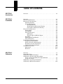
Table of Contents
SECTION 1
Introduction
Overview . . . . . . . . . . . . . . . . . . . . . . . . . . . . . . . . . . . . . . . . . . . . . .
1-1
SECTION 2
Installation
Overview . . . . . . . . . . . . . . . . . . . . . . . . . . . . . . . . . . . . . . . . . . . . . . 2-1
General Considerations . . . . . . . . . . . . . . . . . . . . . . . . . . . . . . . . . . 2-1
Mechanical Considerations . . . . . . . . . . . . . . . . . . . . . . . . . . . . . . . 2-2
Mounting Stability . . . . . . . . . . . . . . . . . . . . . . . . . . . . . . . . . . . 2-2
Access Requirements . . . . . . . . . . . . . . . . . . . . . . . . . . . . . . . . . 2-2
Housing Rotation . . . . . . . . . . . . . . . . . . . . . . . . . . . . . . . . . 2-2
Terminal Side of Electronics Housing . . . . . . . . . . . . . . . . . 2-2
Circuit Side of Electronics Housing . . . . . . . . . . . . . . . . . . 2-2
Electrical Considerations . . . . . . . . . . . . . . . . . . . . . . . . . . . . . . . . . 2-2
Power Supply . . . . . . . . . . . . . . . . . . . . . . . . . . . . . . . . . . . . . . . 2-2
Field Wiring . . . . . . . . . . . . . . . . . . . . . . . . . . . . . . . . . . . . . . . . 2-3
Sensor Connections . . . . . . . . . . . . . . . . . . . . . . . . . . . . . . . . . . 2-4
RTD Inputs . . . . . . . . . . . . . . . . . . . . . . . . . . . . . . . . . . . . . . 2-4
Thermocouple or Millivolt Inputs . . . . . . . . . . . . . . . . . . . . 2-6
Grounding . . . . . . . . . . . . . . . . . . . . . . . . . . . . . . . . . . . . . . . . . . 2-6
Multi-Channel Installations . . . . . . . . . . . . . . . . . . . . . . . . . . . 2-6
Surges/Transients . . . . . . . . . . . . . . . . . . . . . . . . . . . . . . . . . . . 2-6
Environmental Considerations . . . . . . . . . . . . . . . . . . . . . . . . . . . . 2-7
Temperature Environment . . . . . . . . . . . . . . . . . . . . . . . . . . . . 2-7
Moist or Corrosive Environments . . . . . . . . . . . . . . . . . . . . . . . 2-9
Hazardous Location Installation . . . . . . . . . . . . . . . . . . . . . . . . 2-9
Intrinsically Safe Installation . . . . . . . . . . . . . . . . . . . . . . . . . . 2-9
Installation Procedure . . . . . . . . . . . . . . . . . . . . . . . . . . . . . . . . . . . 2-10
Mechanical . . . . . . . . . . . . . . . . . . . . . . . . . . . . . . . . . . . . . . . . . 2-10
Electrical . . . . . . . . . . . . . . . . . . . . . . . . . . . . . . . . . . . . . . . . . . . 2-11
SECTION 3
Calibration
Overview . . . . . . . . . . . . . . . . . . . . . . . . . . . . . . . . . . . . . . . . . . . . . . 3-1
Safety Messages . . . . . . . . . . . . . . . . . . . . . . . . . . . . . . . . . . . . . . . . 3-1
Calibrating a RTD Transmitter . . . . . . . . . . . . . . . . . . . . . . . . . . . . 3-2
Calibrating a Thermocouple Transmitter
Using a Compensated Thermocouple Simulator . . . . . . . . . . . 3-5
Using an Ice Bath . . . . . . . . . . . . . . . . . . . . . . . . . . . . . . . . . . . . 3-7
Calibrating a Low-Power Transmitter . . . . . . . . . . . . . . . . . . . . . . 3-8
Calibrating a Millivolt Transmitter . . . . . . . . . . . . . . . . . . . . . . . . . 3-10
i
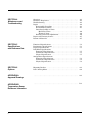
SECTION 4
Maintenance and
Troubleshooting
Overview . . . . . . . . . . . . . . . . . . . . . . . . . . . . . . . . . . . . . . . . . . . . . .
Hardware Diagnostics . . . . . . . . . . . . . . . . . . . . . . . . . . . . . . . . . . .
Troubleshooting . . . . . . . . . . . . . . . . . . . . . . . . . . . . . . . . . . . . . . . .
Repair . . . . . . . . . . . . . . . . . . . . . . . . . . . . . . . . . . . . . . . . . . . . . . . .
Disassembly Procedure . . . . . . . . . . . . . . . . . . . . . . . . . . . . . . .
Reassembly Procedure . . . . . . . . . . . . . . . . . . . . . . . . . . . . . . . .
Interchangeability of Parts
Mechanical Parts . . . . . . . . . . . . . . . . . . . . . . . . . . . . . . . . .
Electrical Parts . . . . . . . . . . . . . . . . . . . . . . . . . . . . . . . . . . .
Burnout Protection Adjustments . . . . . . . . . . . . . . . . . . . . . . . .
Repair and Warranty Service . . . . . . . . . . . . . . . . . . . . . . . . . . . . . .
Return of Materials . . . . . . . . . . . . . . . . . . . . . . . . . . . . . . . . . . . . . .
4-1
4-1
4-1
4-2
4-3
4-5
4-6
4-6
4-6
4-7
4-7
Functional Specifications . . . . . . . . . . . . . . . . . . . . . . . . . . . . . . . . .
Performance Specifications . . . . . . . . . . . . . . . . . . . . . . . . . . . . . . .
Physical Specifications . . . . . . . . . . . . . . . . . . . . . . . . . . . . . . . . . . .
LCD Meter Specifications
Functional Specifications . . . . . . . . . . . . . . . . . . . . . . . . . . . . . .
Performance Specifications . . . . . . . . . . . . . . . . . . . . . . . . . . . .
Physical Specification . . . . . . . . . . . . . . . . . . . . . . . . . . . . . . . . .
Analog Meter Specifications
Functional Specifications . . . . . . . . . . . . . . . . . . . . . . . . . . . . . .
Performance Specifications . . . . . . . . . . . . . . . . . . . . . . . . . . . .
Physical Specification . . . . . . . . . . . . . . . . . . . . . . . . . . . . . . . . .
5-1
5-3
5-3
Mounting Bracket . . . . . . . . . . . . . . . . . . . . . . . . . . . . . . . . . . . . . . .
LCD / Analog Meter . . . . . . . . . . . . . . . . . . . . . . . . . . . . . . . . . . . . .
6-1
6-2
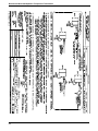
APPENDIX A
Approval Drawings
......................................................
A-1
APPENDIX B
Temperature Sensor
Reference Information
......................................................
B-1
SECTION 5
Specifications
and Reference Data
SECTION 6
Options
ii
5-7
5-7
5-7
5-8
5-8
5-8
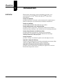
Section
1
OVERVIEW
Introduction
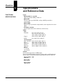
This manual is designed to assist in installing, operating, and
maintaining Rosemount® Model 444 Alphaline® Temperature
Transmitters.
Section 2 Installation
provides mechanical, electrical, and environmental considerations to
guide you through a safe and effective transmitter installation.
Section 3 Calibration
provides different Model 444 calibration procedures.
Section 4 Maintenance and Troubleshooting
provides hardware diagnostics, maintenance tasks, basic hardware
troubleshooting techniques, and considerations for returning materials.
Section 5 Specifications and Reference Data
provides functional, performance, and physical transmitter
specifications; also includes transmitter dimensional drawings,
ordering information, and spare parts.
Section 6 Options
provides a listing of transmitter options and a description of each.
Appendix A Approval Drawings
contains approval drawings for Canadian Standards Association (CSA)
and Factory Mutual (FM) instrinsic safety installation.
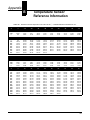
Appendix B Temperature Sensor Reference Information
provides reference information regarding the application of various
Rosemount temperature sensors.
1-1
Rosemount Model 444 Alphaline Temperature Transmitters
1-2
Section
2
OVERVIEW
Installation
This section includes the following transmitter installation
information:
• General Considerations
• Mechanical Considerations
Mounting Stability
Access Requirements
• Electrical Considerations
Power Supply
Field Wiring
Sensor Connections
Grounding
Multi-Channel Installations
Surges/Transients
• Environmental Considerations
Temperature Environment
Moist or Corrosive Environments
Hazardous Location Installation
Intrinsically Safe Installation
• Installation Procedure
Mechanical
Electrical
GENERAL
CONSIDERATIONS
Failure to follow these installation guidelines may result in
death or serious injury. Make sure only qualified personnel
perform the installation.
Explosions can cause death or serious injury. Verify that the
operating atmosphere of the transmitter is consistent with
the appropriate hazardous locations certifications.
Use the Rosemount Model 444 Alphaline Temperature Transmitter
when the temperature measurement point is remote from the control,
readout, or recording point, or where the measurement point is exposed
to environmental conditions that would be harmful to unprotected
signal conditioning equipment.
Electrical temperature sensors such as RTDs and thermocouples
2-1
Rosemount Model 444 Alphaline Temperature Transmitters
produce low-level signals proportional to their sensed temperature. Model 444
temperature transmitters convert the low-level sensor signal to a standard 4–20
mA dc signal that is relatively insensitive to lead length and electrical noise.
This current signal is then transmitted to the control room via two wires.
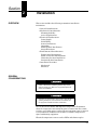
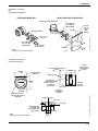
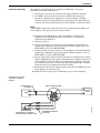
Figures 2-1, and 2-2 show recommended mounting configurations for
transmitter and sensor assemblies. See Section 6 Options for information
regarding Model 444 transmitter accessories.
MECHANICAL
CONSIDERATIONS
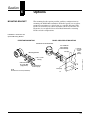
You can attach the transmitter directly to the sensor assembly as shown in
Figures 2-1 and 2-2. An optional mounting bracket permits the transmitter to be
mounted remotely from the sensor(s), either on a flat surface or attached to a
two-inch pipe (See Figure 2-11 on page 2-13). The choice of mounting method
must take into account a number of factors:
Mounting Stability
Mounting stability is an important consideration. The transmitter, though
rugged, may require supplementary support under high-vibration conditions,
particularly if extensive thermowell lagging or long extension fittings are used.
In such instances, the pipestand mounting technique shown in Figure 2-11 on
page 2-13 is preferable.
Access
Requirements
When choosing an installation location and position, take into account the need
for access to the transmitter.
Housing Rotation
You may rotate the transmitter in 90-degree increments to improve field access
to both compartments.
Terminal Side of
Electronics Housing
Make wiring connections through the conduit openings on the terminal side of
the electronics housing. Mount the transmitter so the terminal side is accessible,
and be sure to provide adequate clearance for cover removal.
Circuit Side of
Electronics Housing
The transmitter electronics are installed in the circuit side of the transmitter
housing. In case of electronic malfunction, provide adequate clearance for
circuit-side cover removal. Also, be sure to account for additional clearance if a
meter is to be installed. For more information regarding the meter option, refer
to Section 6 Options.
2-2
Installation
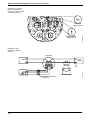
FIGURE 2-1. Recommended
Process Mounting.
Union or Coupling
Thermowell
Hex
Sensor Hex
Extension
Nipple
Transmitter
Conduit for
Field Wiring
(dc Power)
Extension
Length
444-0200C
Thermowell
3.2
(81.3)
NOTE
Dimensions are in inches (millimeters).
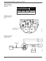
FIGURE 2-2. Recommended
Process Mounting with
Drain Seal.
Union or Coupling
Sensor Hex
Extension
Nipple
Coupling
Close Nipple
Street Ell
Transmitter
Terminal
Side
444-0200F
Drain Seal
Conduit for
Field Wiring
(dc Power)
2-3
Rosemount Model 444 Alphaline Temperature Transmitters
ELECTRICAL
CONSIDERATIONS
This section contains information that you should consider when preparing to
install Model 444 transmitters. Read this section carefully before going on to the
installation procedures. Metal conduit should be used to enclose cabling for best
results in electrically noisy environments.
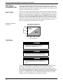
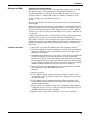
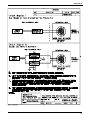
Power Supply
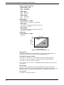
The dc power supply should provide power with less than 2% ripple. The input
voltage versus load limitation relationship for 4–20 mA transmitters is shown in
Figure 2-3. Figure 2-4 shows field wiring for a standard Model 444 transmitter.
Figure 2-5 shows field wiring for Models 444LL and 444LM low-power voltage
output units, which require 100K ohms minimum load. The total R-load is the
sum of the resistance of the signal leads and the load resistance of the controller,
indicators, and related devices. Note that the resistance of intrinsic safety
barriers, if used, must be included in the total load.
FIGURE 2-3. Model 444
Load Limits.
Power Supply Load Limitations
RLOAD (MAX.) = 50 3 (V(MIN.) – 12)
Load (Ohms)
1650
1500
Voltage
Too Low
1000
Operating
Region
500
0
12
20
30
40
Power Supply (V dc)
Field Wiring
Explosions may result in death or serious injury.
Do not remove the instrument cover in explosive
atmospheres when the circuit is alive.
High voltage that may be present on leads can cause
electrical shock. Avoid contact with leads and terminals.
Do not apply high voltage (e.g. ac line voltage) to the
transmitter terminals. Abnormally high voltage can damage
the unit.
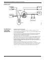
All power to the transmitter is supplied over the signal wiring. Signal wiring
need not be shielded, but use twisted pairs for best results. Do not run
unshielded signal wiring in conduit or open trays with power wiring, or near
heavy electrical equipment. To power the transmitter, connect the positive power
lead to the terminal marked “+” and the negative power lead to the terminal
marked “–” (see Figures 2-4 and 2-5). Tighten the terminal screws to ensure
adequate contact. No additional power wiring is required.
2-4
Installation
FIGURE 2-4. Field Wiring for
the Standard Model 444
Transmitters.
{
(+)
(–)
(+)
(–)
{
Meter Connections
and Signal
Test Points
+
dc Power
–
+
+ –
Optional
Ground
Zero Adjust
FIGURE 2-5. Field Wiring for
Low-Power Model
444 Transmitters
(444LL and LM).
–
+ +
–
Span Adjust
(+) dc Power
Output Voltage (+)
444-0000C02A
RTD Input
(typical)
Output Load Limitation
Minimum Load = 100K
(–) Common
Shield
A to D
Converter
444-0000A02A
Power
Supply
RTD Input
Optional
Ground
Zero Adjust
Span Adjust
Sensor
Connections
Explosion may result in death or serious injury. Do not
remove the instrument cover in explosive atmospheres
when the circuit is alive.
High voltage that may be present on leads can cause electrical
shock. Avoid contact with the leads and the terminals.
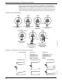
RTD Inputs
Various RTD configurations are used in industry; each configuration offers a
specific solution for compensating the effects of lead wire resistance. They
include 3- and 4-wire designs. The correct installation for each of these RTDs is
shown in Figures 2-6a and b on page 2-6.
If the transmitter is mounted remotely from the RTD, operation will be
satisfactory, without recalibration, for lead wire resistances of up to 2 ohms per
lead (equivalent to 200 feet of 20 AWG wire). In this case, the leads between the
RTD and transmitter should be shielded.
2-5
Rosemount Model 444 Alphaline Temperature Transmitters
The correct connections for a compensation loop RTD and a 2-wire RTD are
shown in Figure 2-6c and Figure 2-6d, respectively. In a 2-wire RTD, however,
both leads are in series with the sensor element, so significant errors (0.1 °C)
could occur if the lead lengths are greater than one foot. For longer runs when
using a 2-wire RTD, attach a third lead and connect as shown in Figure 2-6a.
FIGURE 2-6. Sensor Wiring Diagrams.
Model 444 with 4-Wire RTD
Figure 2-6a
Figure 2-6b
Jumper
Model 444 with
Comp. Loop RTD
White
Red
Signal
+
–
White
Red
Black
Model 444 with 3-Wire RTD
Black
Signal
+
–
White
Red
White
Red
Red
Signal
+
–
White
Red
Signal
+
–
Model 444 with 2-Wire RTD
Figure 2-6d
Figure 2-6c
Signal
+
–
+
Model 444LL or 444LM
with 3-Wire RTD
Figure 2-6e
+
Low T/C
High T/C
–
+ +
–
–
444-0203A;B;C;D
Red
Signal
+
–
White
Red
Signal
+ Output
Common –
–
Model 444MV with Millivolt
Input or Model 444T Series
with Grounded or
Ungrounded Thermocouple
Model 444MV used as
Differential Millivolt
Transmitter (T/C Junctions
must be ungrounded)
Figure 2-6g
Figure 2-6f
FIGURE 2-7. Characteristics of Thermocouple and RTD Input Wires.
Thermocouple Type
J
K
T
E
R
S
Single Element RTD
Red
Positive Lead
Negative Lead
Iron (Magnetic)
Chromel (Non-magnetic)
Copper (Yellow color)
Chromel (Shiny metal)
Platinum 13% Rhodium
Platinum 10% Rhodium
Constantan (Non-magnetic)
Alumel (Magnetic)
Constantan (Silver color)
Constantan (Dull metal)
Platinum
Platinum
Compensation Loop RTD
Red
Dual Element RTD
Red
Red
White
White
White
White
2-6
Black
Black
Black
Green
Green
444-0207A
White
Installation
Thermocouple or
Millivolt Inputs
In the case of thermocouples, make connections between the sensor and the
transmitter with thermocouple wire. For process mounting applications, connect
the thermocouple directly to the transmitter. For installations where the
transmitter is mounted remotely from the sensor, use appropriate thermocouple
extension wire. As with all low-level signal wiring, shielding is recommended for
long runs. Make input connections for the Model 444MV Millivolt Transmitter
using copper wires. The correct connections for thermocouple and millivolt
inputs are shown in Figures 2-6f and g.
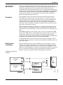
Grounding
The transmitter will operate with the current signal loop either floating or
grounded. However, many types of readout devices are affected by the extra
noise in floating systems. If operation appears noisy or erratic, grounding the
current signal loop at a single point may solve the problem. The negative
terminal of the power supply is the best place to ground the loop. Alternately,
either side of the readout device could be grounded. Do not ground the current
signal loop at more than one point.
Thermocouple and millivolt transmitters are isolated, so the input circuit also
may be grounded at any single point (when a grounded thermocouple is used,
this point is the grounded junction), and the signal loop may be grounded at any
point.
The 444RL transmitter is not isolated, so there can be no grounds in the RTD
circuit. Since RTDs must be well-insulated from ground in order to give correct
temperature readings, this is not normally an installation limitation. The
positive side of the power supply should not be grounded for use with RTD input
transmitters. The 444RI9 should be used with grounded RTDs.
If using shielded wire, connect the shield of the sensor-to-transmitter cable to
the shield of the transmitters-to-receiver cable. Ground the shielding only at the
signal loop ground.
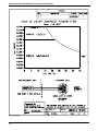
Figure 2-8 illustrates how several transmitters can be connected to a single
master power supply. In this instance, the system can be grounded only at the
negative power supply terminal. Since several channels are dependent on one
supply, an uninterruptible power supply or backup battery should be considered
if loss of all channels would pose operational problems. The diodes shown in
Figure 2-8 prevent unwanted charging or discharging of the battery.
Multi-Channel
Installations
FIGURE 2-8. Multi-Channel
Installation.
+
Transmitter
No. 1
+
Backup
Battery
Readout or
Controller No. 1
dc
Power
Supply
–
–
444-0202A
Transmitter
No. 2
Readout or
Controller No. 2
To Additional
Transmitters
2-7
Rosemount Model 444 Alphaline Temperature Transmitters
Surges/Transients
The transmitter will withstand electrical transients of the energy level usually
encountered in static discharges or induced switching transients. However, highenergy transients, such as those induced in wiring from nearby lightning strikes,
can damage both the transmitter and the sensor.
To protect against high-energy transients, install Model 444 transmitters in
conjunction with the Rosemount Model 470 Transient Protector. The Model 470
prevents damage from transients induced by lightning, welding, heavy electrical
equipment, or switch gears. Refer to the Model 470 Transient Protector product
data sheet, pub. no. 00813-0100-4191 for more information.
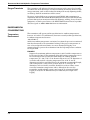
ENVIRONMENTAL
CONSIDERATIONS
Temperature
Environment
The transmitter will operate within specifications for ambient temperatures
between –25 and 85 °C. It will function, but not necessarily within specifications,
in ambient temperatures between
–40 and 100 °C.
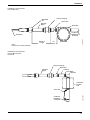
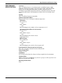
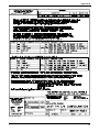
Aside from ambient temperature variations, heat from the process is transferred
from the thermowell to the transmitter housing. If the process temperature is
near or beyond specification limits, use excess thermowell lagging or an
extension nipple to protect the transmitter from the high temperature condition.
See Figure 2-10.
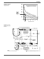
EXAMPLE:
Suppose the maximum ambient temperature is 40 °C and the temperature to
be measured is 540 °C. The maximum allowable housing temperature rise is
the rated temperature specification limit minus the existing ambient
temperature (85 – 40), or 45 °C. As shown in Figure 2-9, an “E” dimension of
3.6 inches will result in a housing temperature rise of 22 °C. An “E”
dimension of 4 inches would therefore be the minimum recommended length,
and would provide a safety factor of about about 25 °C. A longer “E”
dimension, such as 6 inches, would be desirable in order to reduce errors
caused by transmitter temperature effect, although in that case the
transmitter would probably require extra support. If a thermowell with
lagging is used, the “E” dimension may be reduced by the length of the
lagging.
2-8
Installation
FIGURE 2-9. Model 444
Transmitter Housing
Temperature Rise.
60
(108)
Transmitter Housing Temperature Rise
vs. E Length for a Test Installation
50
(90)
40
(72)
30
(54)
22
81
5
20
(36)
540
250
10
(18)
°C (
°C
482
°
°C
(
(10
0
F)
15
00
°
0 °F
F)
Ove
n Te
m pe
) Ove
n Te
ratu
re
mperatu
re
3044-0123A
HOUSING
RISE
ABOVE
AMBIENT
°C (°F)
Oven Temperatu
re
0
3
4
5
3.6
6
7
8
9
E Length in Inches
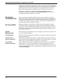
FIGURE 2-10. Sensor
Assembly Dimensional
Drawings.
Connection Head with Extended Cover
Bayonet Spring Loaded Sensor
½–14 NPT Thread
Sensor Installed in
Connection Head
(Extended Cover)
with Coupling and
Nipple Extension
0.25
(6)
L
Sensor X Length (Ref.)
5.5
(140)
3.5
(89)
1.0
(25)
Nominal Fitting
E
V
Length
2.2
(56)
0.53 (13) Max.
Thread
Engagement
Spring Loaded Sensor
¾–14 NPT
NOTE
Dimensions are in inches (millimeters).
Chain
T (1) + 1.75 (44)
Sensor Installed in
Connection Head (Flat
Cover) with Union and
Nipple Extension and
Thermowell
¾–14 NPT
on Thermowell
U
T (1)= 0.0 on Standard Assembly Thermowells
Sensors-0000A06A
Connection Head with
Flat Cover
2-9
Rosemount Model 444 Alphaline Temperature Transmitters
Moist or Corrosive
Environments
The transmitter is designed to resist attack by moisture and other corrosives.
The coated circuit boards are mounted in a compartment completely sealed from
the conduit entrances. O-ring seals protect the interior when the covers are
installed. In humid environments, however, it is still possible for moisture
“breathing” to occur in conduit lines. If the transmitter is mounted at a low point
in the conduit run, the terminal compartment could fill with water, causing
electrical shorting. The transmitter should be mounted so moisture from the
conduit will not drain into the housing. In some instances a drain seal, installed
as shown in Figure 2-2 on page 2-3, is advisable.
Hazardous Location
Installation
Explosions may result in death or serious injury. Verify that
the operating atmosphere of the transmitter is consistent
with the appropriate hazardous locations certifications.
Explosions may result in death or serious injury. Both
transmitter covers must be fully engaged to meet explosionproof requirements.
The Model 444 is designed with an explosion-proof housing and circuitry
suitable for intrinsically safe and non-incendive operation. Individual
transmitters are clearly marked with a tag indicating the approvals they carry.
The various approvals are available as options. Refer to Section 5
Specifications and Reference Data for a complete listing of available
approvals.
To maintain certified ratings for installed transmitters, install in accordance
with applicable installation codes and approval drawings. Refer to Appendix A
Approval Drawings for Model 444 installation drawings. For future orders,
refer to the current product price list for the most up-to-date information on
these approvals.
Intrinsically Safe
Installation
For explosion-proof installations, installation location must
be made in accordance with Rosemount drawing 004440261, Rev. E.
For intrinsically safe installations, installation location must
be made in accordance with Rosemount drawing 004440034, Rev. C (CSA) or 00444-0264, Rev. B (SAA).
You can use Intrinsically safe installations instead of explosion-proof
installations in hazardous areas. In such configurations, the transmitter and
sensor are located in a hazardous area, and the current signal leads are
connected to equipment in a non-hazardous area through intrinsic safety
barriers that limit the voltage and current fed into the hazardous area. Install in
accordance with the barrier manufacturer’s instructions for the specific barrier
used. For approval information, refer to Table 5-1 on page 5-4, and Table 5-2 on
page 5-5. For installation information, refer to the intrinsically safe barrier
systems reference drawings in Appendix A Approval Drawings.
2-10
Installation
INSTALLATION
PROCEDURE
Installation consists of mounting the transmitter and sensor assembly and
making electrical connections. If mounting the transmitter directly to the sensor
assembly, use the process mounting technique shown in Figure 2-1 or Figure 2-2,
on page 2-3. For transmitter locations remote from the sensor, use conduit
between the sensor and transmitter. Transmitter hubs will accept male conduit
fittings with ½–14 NPT; ½–14 NPSM; or ½–14 taper thread per ANSIC 80.4.
Explosion may result in death or serious injury. Do not
remove the instrument cover in explosive atmospheres
when the circuit is alive.
High voltage that may be present on leads may cause
electrical shock. Avoid contact with the leads and the
terminals.
Process leaks may result in death or serious injury. Install
and tighten thermowells or sensors before applying
pressure, or process leakage may result. Removing the
thermowell or sensor while in operation may cause process
fluid leaks.
Mechanical
1. Mount the thermowell to the pipe or process container wall.
2. Attach any necessary extension nipples and adapters. Seal the nipple and
adapter threads with silicone or tape.
3. Screw the sensor into the thermowell.
4. Install drain seals if required for severe environments or to satisfy code
requirements (See Figure 2-2 on page 2-3).
5. Attach the transmitter to the thermowell assembly. Seal the adapter
threads with silicone or tape.
6. Install conduit for field wiring to the remaining conduit entry of the
transmitter. Seal conduit threads with silicone or tape.
7. Pull field wiring leads through the conduit into the terminal side of the
transmitter housing.
Electrical
For explosion-proof installations, wiring connections must
be made in accordance with Rosemount drawing 004440261, Rev. E.
For intrinsically safe installations, wiring connections must
be made in accordance with ANSI/ISA-RP12.6, and
Rosemount drawing 00444-0034, Rev. C (CSA) or 004440264, Rev. B (SAA).
For all installations, wiring connections must follow the
National Electric Code.
2-11
Rosemount Model 444 Alphaline Temperature Transmitters
Preliminary Checkout
1. For any Model 444 unit, first verify that the transmitter is calibrated to
the required range. Calibration is usually performed by substituting an
input in place of the sensor, and this is most conveniently accomplished
prior to sensor connection. Refer to the calibration procedures in Section
4 Maintenance and Troubleshooting.
Input Connections
2. Model 444RL: Connect the RTD leads as shown in Figure 2-6a, b, c, d, or
e depending upon the lead compensation method used.
Model 444T series: Connect the thermocouple leads as shown in Figure
2-6f. Polarity is important; be sure to identify the leads accurately. The
negative lead is usually red; if there is no color coding, the characteristics
provided in Figure 2-7 may be helpful.
Model 444MV: If using the transmitter as a millivolt-to-milliampere
converter, use ordinary copper leads for input connections as shown in
Figure 2-6f. If using the transmitter with two thermocouples to measure
differential millivolt, connect the thermocouples as shown in Figure 2-6g.
The “high” thermocouple causes the transmitter output to increase when
its temperature increases relative to the “low” thermocouple. Grounded
thermocouples cannot be used for differential measurements.
Models 444LL and LM: In these low-power option packages, the RTD
leads are connected the same as in the conventional RTD arrangements
shown in Figure 2-6a, b, c, and d.
Output Connections
3. For all 4–20 mA models, use ordinary copper wire of sufficient size to
assure that the voltage across the transmitter power terminals does not go
below 12 V dc (See Figure 2-3). For multi-channel or intrinsically safe
installations, see applicable paragraphs in this section.
Model 444RL: Connect current signal leads as shown in Figure 2-6a, b, c,
or d.
Model 444T series: Connect current signal leads as shown in Figure 2-6f.
Model 444MV: Connect current signal leads as shown in Figure 2-6f or g.
Models 444LL and LM: Connect current signal leads as shown in Figure
2-6e.
Final Checkout
4. For all models, recheck the polarity and correctness of connections; then
turn the power on.
2-12
Installation
FIGURE 2-11. Model 444
with
Optional Mounting Bracket.
PANEL OR SURFACE MOUNTING
PIPESTAND MOUNTING
Transmitter can be Rotated 90°
5/16 -inch
Bolts
(four required,
not furnished)
Hole for
/16 -inch
Bolts
(four
places)
5
2.81 (81)
Mounting Bracket
Clearance Hole
for ¼-inch Bolt
(eight places)
444-1151G, 1151F04A
¼–20 3½-inch
Bolt (4)
5
/16 –18 U-bolt for
2-inch Pipe (2)
5.00 (127)
NOTE
Dimensions are in inches (millimeters).
FIGURE 2-12. Model 444
Dimensional Drawings
0.75 (19)
Clearance for
Cover Removal
(Typical)
7.5 (191) Max. with Optional
Meter
4.5 Max.
(114)
Permanent Tag
(Optional)
4.5 Max.
(114)
4.5 Max.
(114)
Meter Housing
½–14 NPT per
ANSI C80.4 for
Conduit or Sensor
Connection
(two places)
4.2
(117)
Terminal
Circuitry
this Side
Explosion Proof or
Intrinsic Safety Label
(Optional)
444-51LTE 05A, 51LTG 05A, 51LTF 05A
Terminal
Connections
this Side
Nameplate
0.36 (9)
0.72 (18)
Mounting Holes
¼–20 UNC–2B
0.375 (10) Min. Dp.
(four places)
NOTE
Dimensions are in inches (millimeters).
0.87 (22)
1.7
(44)
2-13
Rosemount Model 444 Alphaline Temperature Transmitters
2-14
Section
3
OVERVIEW
Calibration
Each transmitter is factory calibrated to the temperature range shown
on the nameplate. If calibration to a specific range is not specified on
the purchase order, the transmitter is calibrated to maximum span
with a base temperature of 0 °C, and the “Calibration” entry on the
transmitter nameplate is left blank. For more specific calibration
information and a complete breakdown of transmitter parts, refer to
Section 5 Specifications and Reference Data.
Only a few calibration laboratories have the kind of precision
temperature baths necessary for accurate direct calibration of a
temperature sensor or sensor/transmitter system. As a result, the
transmitter is normally calibrated by substituting a resistance decade
box for an RTD or a compensated thermocouple simulator for a
thermocouple.
This section contains the following transmitter calibration information:
• Calibrating a RTD Transmitter
• Calibrating a Thermocouple Transmitter
• Calibrating a Low-Power Transmitter
• Calibrating a Millivolt Transmitter
SAFETY MESSAGES
This section contains procedures that require removing the transmitter
covers and making electrical connections. The following safety
messages apply to all such procedures.
Explosion may result in death or serious injury. Do not
remove the instrument cover in explosive atmospheres
when the circuit is alive.
High voltage that may be present on leads can cause
electrical shock. Avoid contact with the leads and the
terminals.
3-1
Rosemount Model 444 Alphaline Temperature Transmitters
CALIBRATING A
RTD TRANSMITTER
Calibration Equipment Required:
Readout Resistor. The transmitter test terminals give a 40–200 mV signal. The
Models 444RL and444RL ___B0912 have a jumper-selectable 4–20 mA test
output option (2-board sets). If this is not suitable for the test equipment
available, a ±0.1% tolerance, 0.5 W precision wirewound resistor is needed.
Suggested values include a 100-ohm resistor to give a 0.4 to 2 volt output; or 500
ohms for 2 to 10 volts.
Voltmeter (such as a 5-digit DVM). Voltage rating is dependent upon the test
signal. Accuracy is ±0.01%; resolution is 1 mV.
dc Power Supply. Power capability is 24 V dc at 35 mA.
Resistance Decade Box. Precision type, 5-dial, with largest dial providing 100ohm steps. Accuracy is ±0.02 ohm. The decade box should be periodically
calibrated against a 5-dial Wheatstone bridge.
Lead Simulation Resistors. If the transmitter is to be mounted remote from the
RTD, and the lead resistance between the transmitter and the RTD is greater
than 2 ohms per lead (equivalent to 200 ft of 20 AWG wire), the transmitter
should be trimmed with simulated lead resistances for best accuracy. This
requires wirewound resistors with resistance values equal to the nominal lead
resistance of the RTD.
Calibration Procedure
To calibrate a model 444RL or 444RL___B0912, perform the following procedure:
1. The Models 444RL and 444RL ___B0912 have a jumper-selectable 4–20
mA test output option. If a 4–20 mA test output is required, reposition the
test terminal output jumper on the range board (the default setting is 40–
200 mV). Refer to steps 2 through 4 of the disassembly procedure, on page
4-4, for information on removing the circuit board assembly.
Place the jumper in the position labelled “A” for a 4–20 mA test output. See
Figure 3-1. Refer to steps 5 through 12 of the reassembly procedure, on
page 4-5, for information on reinstalling the circuit board assembly.
2. Remove the cover from the terminal side of the transmitter housing.
3. If an RTD is already connected, remove all RTD lead connections.
4. Attach the calibration test equipment as shown in Figure 3-2. Use
miniature banana plugs to make terminal connections. Use simulated lead
resistors only if necessitated by long lead wire lengths, as discussed above.
NOTE
If using RTD configurations other than the 3-wire design shown in Figure 3-2,
refer to Figure 2-6 on page 2-6 for the correct wiring.
5. If trimming the transmitter to a new range, you may have to reposition the
Coarse Zero Jumper on the Range Board. If so, see the disassembly
procedure on page 4-4. Position the jumper in the location shown in Table
3-1. (A transmitter with a Base Temperature outside the regions shown in
Table 3-1 is a special design, and does not contain a Coarse Zero Jumper.)
Reassemble the circuit boards.
3-2
Calibration
6. Determine the RTD resistance at the desired base and full scale
temperatures. For Calibration Code 1 (see Table 5-3, on page 5-9), these
resistances are listed in Table B-1.
7. Turn the power on.
8. Set the decade box to the resistance corresponding to the desired base
temperature. Adjust the zero potentiometer until the output is 4 mA.
Remember that recovery time of the unit from an underscale condition is
longer than from an over-scale condition. Therefore, set the box to a higher
resistance than that desired, then bring it down to the correct value.
9. Set the decade box to the resistance corresponding to the desired full scale
temperature. Adjust the span potentiometer until the output is 20 mA.
10. Repeat steps 8 and 9 until you obtain the 4 and 20 mA readings without
readjusting the span and zero potentiometers. Complete this process more
quickly by noting the full scale reading before readjusting the span pot,
using the span pot to overshoot the desired reading by 20%, and then
using the zero pot to readjust the full scale reading to 20 mA.
EXAMPLE:
To calibrate the Model 444RL1U1 for a range of 100 to 150 °F (38 to 66 °C),
first consult Table 3-1, and plug the jumper into pins Z2. From Table B-1,
trim points are 114.68 and 125.37 ohms corresponding to 100 °F and 150 °F
respectively. After adjusting the base to 4 mA, and setting the decade to full
scale resistance, output equals 22.5 mA, or 2.5 mA greater than desired. Set
the span pot to an output lower than 20 mA by the amount equal to 20% of
2.5 equals 0.5 mA, or 19.5 mA. Reset the zero pot so the output equals 20 mA.
Repeat steps 8 and 9 and this procedure until readjustments are no longer
necessary.
11. Disconnect the decade box and the readout resistor. Reconnect the RTD
and power leads. Replace the terminal cover.
12. Mark the correct range in the “Calibration” space on the nameplate
TABLE 3-1. Coarse Jumper
Location, Model 444R.
.
Base Temperature
Region
Jumper Location
°C
°F
444RL1
444RL2
444RL3
–50 to 0
0 to 50
50 to 100
100 to 150
–58 to 32
32 to 122
122 to 212
212 to 302
Z1
Z2
Z3
Z4
Z1
Z1
Z2
Z2
Continuously
adjustable
(no jumper)
NOTE
If the base temperature is at a dividing point between regions, use the
lower jumper position optimum performance; i.e., use location Z1 rather
than Z2 for Model 444RL1 with a base temperature of 0 °C.
3-3
Rosemount Model 444 Alphaline Temperature Transmitters
FIGURE 3-1. Location of
Test Input and Burnout
Protection Jumper on Model
444RL Range Board.
444-0002ACCA
Test Output
Jumper Position
Burnout Protection
Jumper Position
FIGURE 3-2. RTD
Transmitter Calibration
Diagram.
Transmitter
Power
Supply
DVM
Readout
Resistor
Decade Box
Alternate Readout
Lead Simulator Resistors
(If required)
3-4
444-0215A
DVM
Calibration
CALIBRATING A
THERMOCOUPLE
TRANSMITTER
Using a
Compensated
Thermocouple
Simulator
Calibration Equipment Required
Compensated Thermocouple Simulator. Precision voltage source providing
conformity to NIST Monograph 125 thermocouple curves. Reflect accuracy of
simulator to desired calibration span. A simulator accuracy four times better
than the transmitter is recommended (0.05% of calibrated span or 0.005mV
whichever is greater). Simulator inaccuracies greater than this will degrade
system accuracy and factory calibration is recommended.
Voltmeter. Such as a 5-digit DVM. Accuracy is ±0.01%; resolution is 1 mV.
dc Power Supply. Power capability is 24 Vdc at 35 mA.
Thermocouple Wire.Use the same type as that used in the construction of the
thermocouple.
Readout Resistor. The transmitter test terminals give a 40–200 mV signal. If
this is not suitable for the test equipment available, a ±0.1% tolerance, 0.5 W
precision wirewound resistor is needed. Suggested values include a 100-ohm
resistor to give a 0.4 to 2 volt output; 250 ohms for 1 to 5 volts; or 500 ohms for
2 to 10 volts.
Calibration Procedure
1. Remove the cover from the terminal side of the transmitter housing.
2. If a thermocouple is already connected, remove all thermocouple lead
connections.
3. Connect the equipment as shown in Figure 3-4. Be sure to maintain
polarity from the transmitter to the thermocouple simulator. Make
terminal connections using miniature banana plugs.
4. If trimming the transmitter to a new range, you may have to reposition the
Coarse Zero Jumper on the Range Board. If so, see the Disassembly
Procedure on page 4-4. Position the jumper in the location shown in Table .
(A transmitter with a base temperature outside the regions shown in Table
is a special design and does not contain a Coarse Zero Jumper. Also, Model
444 TR and TS transmitters do not have Coarse Zero Jumpers.)
Reassemble the circuit boards.
5. Determine the base and full scale temperatures.
6. Turn the power on.
7. Refer to the thermocouple simulator instructions for setting the
thermocouple type and engineering units. Set the simulator to the base
(zero) temperature and adjust the zero pot until the output is 4 mA (or 40
mV at the test terminals).
8. Set the simulator to the full scale temperature and adjust the span pot
until the output is 20 mA (or 200 mV at the test terminals).
9. Repeat steps 7 and 8 until you obtain the 4 and 20 mA readings without
readjusting the pots. Use the “overshoot” technique described in step 9 of
the RTD calibration procedure, if desired.
10. Disconnect the simulator leads. Reconnect the thermocouple and power
leads, if required. Replace the terminal side housing cover.
11. Mark the new range in the “Calibration” space on the nameplate.
3-5
Rosemount Model 444 Alphaline Temperature Transmitters
TABLE 3-2. Coarse Zero
Jumper Location, Model
444TJ, TK, TF, TT, and MV
Range Code 1.
Transmitter Base Region
°C
°F
mV
–50 to 50
50 to 100
–58 to 122
122 to 302
-2 to 3
3 to 8
Coarse Zero
Jumper Location
Z1
Z2
NOTE
Range Codes 2 and 3 are continuously adjustable over the range
shown in Table 1. (No Coarse Zero Jumper)
FIGURE 3-3. Location of
Burnout Protection Jumper
on Model 444T Range
Board.
FIGURE 3-4. Compensated
Thermocouple Simulator
Calibration Diagram.
444-0010ACCA
Burnout R2, R3
Protection Resistors
.
–
DVM
+
Thermocouple
Wire
+
Power
Supply
Readout Resistor
+
+
–
–
–
+
–
Transmitter
DVM
(Alternate Readout)
3-6
444-0216A
Thermocouple
Simulator
Calibration
Using an Ice Bath
Calibration Equipment Required
Millivolt Source. Precision voltage source providing outputs from –10 to 100
mV. Reflect accuracy of four times better that the 444 transmitter is
recommended (0.05% of calibrated span or 0.005 mV which ever is greater).
Voltmeter. Such as a 5-digit DVM. Accuracy is ±0.01%; resolution is 1 mV.
dc Power Supply. Power capability is 24 V dc at
35 mA.
Thermocouple Wire.Use the same type as that used in the construction of the
thermocouple.
Readout Resistor. The transmitter test terminals give a 40–200 mV signal. If
this is not suitable for the test equipment available, a ±0.1% tolerance, 0.5 W
precision wirewound resistor is needed. Suggested values include a 100-ohm
resistor to give a 0.4 to 2 volt output; 250 ohms for 1 to 5 volts; or 500 ohms for
2 to 10 volts.
Ice Bath. For highest accuracy, a stirred ice bath (such as a Rosemount 911A)
should be used, as well as ice made from deionized or distilled water.
Input Monitor Voltmeter. Use to monitor source when required. Resolution of
±0.001 mV for ranges up to 100 mV. This can be the same as voltmeter used to
measure transmitter output if rangeability and resolution are sufficient for
both levels.
Calibration Procedure
1. Remove the cover from the terminal side of the transmitter housing.
2. Install the equipment as shown in Figure 3-5 and allow the thermocouple
junctions to stabilize at the ice point. Make terminal connections with
miniature banana plugs.
3. If trimming the transmitter to a new range, you may have to reposition the
Coarse Zero Jumper on the Range Board. If so, see the disassembly
procedure on page 4-4. Position the jumper in the location shown in Table .
(A transmitter with a base temperature outside the regions shown in Table
is a special design and does not contain a Coarse Zero Jumper. Also, Model
444 TR and TS transmitters do not have Coarse Zero Jumpers.)
4. Determine the thermocouple millivolt levels at the desired base and full
scale temperatures. See NIST Monograph 125 or
Table B-1.
5. Turn the power on.
6. Set the millivolt source until the monitoring voltmeter reads the emf
corresponding to the desired base temperature. Adjust the zero pot until
the output is 4 mA.
7. Set the millivolt source until the monitoring voltmeter reads the emf
corresponding to the desired full scale temperature. Adjust the span pot
until the output is 20 mA.
8. Repeat steps 6 and 7 until you obtain the 4 and 20 mA readings without
readjusting the pots. Use the “overshoot” technique described in step 9 of
the RTD calibration procedure, if desired.
9. Mark the correct range in the “calibration” space on the nameplate.
3-7
Rosemount Model 444 Alphaline Temperature Transmitters
FIGURE 3-5. Ice Bath
Calibration Diagram.
Input
Monitor
DVM
+
–
DVM
+
–
Thermocouple
Wire
+
Power
Supply
Millivolt
Source
–
+
+
–
–
–
+
DVM
Ice Bath
CALIBRATING A
LOW-POWER
TRANSMITTER
Calibration Equipment Required
Voltmeter. Such as a 5-digit DVM. Accuracy is ±0.01%; resolution is 1 mV.
dc Power Supply. Power capability is 5 V dc at 1.5 mA for Model 444LL and 8 V
dc at 2 mA for Model 444LM.
Resistance Decade Box. Precision type, 5-dial, with largest dial providing 100ohm steps. Accuracy is ±0.02 ohm. The decade box should be periodically
calibrated against a 5-dial Wheatstone bridge.
Lead Simulation Resistors. If the transmitter is to be mounted remote from the
RTD, and the lead resistance between the transmitter and the RTD is greater
than 2 ohms per lead (equivalent to 200 ft of 20 AWG wire), the transmitter
should be trimmed with simulated lead resistances for best accuracy. This
requires wirewound resistors with resistance values equal to the nominal lead
resistance of the RTD.
Load Resistor. If the transmitter is to be operated with a load that is
significantly different from the DVM used for calibration, a load resistor can be
used for best calibration accuracy. A metal film, carbon comp, or wirewound
resistor, as well as a decade box can be used to simulate the actual load.
3-8
444-0217A
(Alternate Readout)
Calibration
Calibration Procedure
The following steps describe the procedure for calibrating a low-power
transmitter, as shown in Figure 3-6:
1. Remove the cover from the terminal side of the transmitter housing.
2. If an RTD is already connected, remove all RTD lead connections.
3. Attach the calibration test equipment as shown in Figure 3-6. Make
terminal connections using miniature banana plugs. Use simulated lead
resistors only if necessitated by long lead wire lengths, as discussed above.
NOTE
If using RTD configurations other than the 3-wire design shown in Figure 3-2,
refer to Figure 2-6 on page 2-6 for the correct wiring.
4. Determine the RTD resistance at the desired base- and full-scale
temperatures. For Calibration Code 1 (see Table 5-5), obtain these
resistances from Table B-1.
5. Turn the power on.
6. Set the decade box to the resistance corresponding to the desired base
temperature. Adjust the zero potentiometer until the output is 0.8 V for
Model 444LL or 1.0 V for Model 444LM.
7. Set the decade box to the resistance corresponding to the desired full-scale
temperature. Adjust the span potentiometer until the output is 3.2 V for
Model 444LL or 5.0 V for Model 444LM.
8. Repeat steps 6 and 7 until you obtain both the zero- and full-scale readings
without adjusting the span and zero potentiometers. Complete this process
more quickly by noting the full-scale reading before readjusting the span
pot, using the span pot to overshoot the desired reading by 20%, and then
using the zero pot to readjust the full scale reading.
9. Disconnect the decade box and the readout. Reconnect the RTD and power
leads. Replace the terminal cover.
10. Mark the correct range in the “Calibration” space on the nameplate.
FIGURE 3-6. Low-Power
Transmitter Calibration
Diagram.
Load Resistors ➀
(If required)
444LL and LM Transmitter
+
+
dc Power
Source
DVM
–
–
➀Transmitters are calibrated
at the factory with a 220 K V load.
444-0218A
Decade Box
Lead Simulator Resistors
(If required)
3-9
Rosemount Model 444 Alphaline Temperature Transmitters
CALIBRATING A
MILLIVOLT
TRANSMITTER
3-10
Calibration is identical to the thermocouple type (see Figure 3-5 on page 3-8),
except that a reference junction and ice bath are not used. The millivolt source is
connected directly to the transmitter input terminals with copper wire, and the
desired millivolt levels are entered directly. See Table 3-2 for Coarse Zero
Jumper locations.
Section
4
OVERVIEW
Maintenance and
Troubleshooting
This section contains the following transmitter maintenance and
troubleshooting information:
Hardware Diagnostics
• Troubleshooting
• Repair
Disassembly Procedure
Reassembly Procedure
Interchangeability of Parts
Burnout Protection Adjustments
• Repair and Warranty Service
• Return of Materials
Use only the procedures and new parts specifically
referenced in this manual. Unauthorized procedures or
parts can affect product performance and the output signal
used to control a process, and may render the instrument
dangerous. Direct any questions concerning these
procedures or parts to Rosemount Inc.
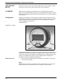
HARDWARE
DIAGNOSTICS
If you suspect a malfunction, refer to Table 4-1 to verify that
transmitter hardware and process connections are in good working
order. Under each of the seven major symptoms, you will find specific
suggestions for solving the problem. Always deal with the most likely
and easiest-to-check conditions first.
TROUBLESHOOTING
This section offers tips for troubleshooting several kinds of potential
malfunctions. To determine a malfunction, use pin-like probes to break
through the protective coating to make measurements on a circuit
board.
4-1
Rosemount Model 444 Alphaline Temperature Transmitters
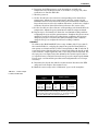
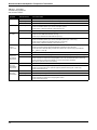
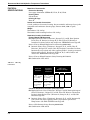
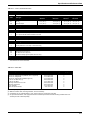
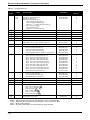
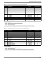
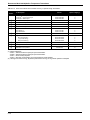
TABLE 4-1. Transmitter
Troubleshooting Symptoms
and Corrective Actions.
Symptom
High Output
Erratic Output
Low Output or
No Output
Excessive
Current
(over 30 mA)
Potential Source
Corrective Action
Sensor
Check for a sensor or thermocouple open circuit. (RL, MV, T-Series with upscale burnout protection only)
Loop Wiring
Check for dirty or defective terminals, interconnecting pins, or receptacles.
Electronics Assembly
Check for dirty or defective interconnecting pins.
Loop Wiring
Check for adequate voltage to the transmitter.
Check for intermittent shorts, open circuits, and multiple grounds.
Check for dirty or defective terminals or interconnection pins.
Electronics Assembly
Check for dirty or defective interconnecting pins.
Sensor
Check RTD leads to ensure that they are not shorting together or to ground. (RL only)
Check for correct RTD lead connection. (RL only)
Check for open RTD lead on double-lead side. (RL only)
Loop Wiring
Check for adequate voltage to the transmitter. (RL only)
Check for intermittent shorts, open circuits, and multiple grounds. (MV, T series only)
Check for proper polarity at the signal terminal. (MV, T series only)
Check for dirty or defective terminals or interconnection pins.
Loop Wiring
Check for short between current signal leads.
Check to ensure that current signal leads ARE NOT connected to sensor terminals.
Check that sensor leads ARE NOT grounded when positive side of power supply is grounded (RL,
RL___B0912, LL, and LM)
Electronics Assembly
Check for defective components in amplifier or current control section.
Excessive
Output Shift
with Ambient
Temperature
Sensor
Check for incorrect thermocouple type or Incorrect thermocouple polarity connection (T series only)
Electronics Assembly
Check to ensure that the burnout -protection jumpers positioned correctly (MV, T series only).
Check for defective components in voltage regulator or dc-to-ac converter section (MV, T series only).
Check for defective components in amplifier or current control section (all models).
May require replacement electronics assembly.
Unit Cannot be
Trimmed to
Desired Base
Temperature
Transmitter
Check to ensure that unit is capable of desired range.
Electronics Assembly
Check to ensure that the range board jumper is in the correct position.
Check to ensure that the burnout -protection jumpers positioned correctly. (MV, T series only).
Check for defective zero pot.
Unit Cannot be
Trimmed to
Desired Span.
Transmitter
Check to ensure that unit is capable of desired range.
4-2
Loop Wiring
Check for adequate voltage to the transmitter.
Electronics Assembly
Check for defective components in amplifier or current control section.
Check for defective components in voltage regulator section.
Check for defective span pot.
Maintenance and Troubleshooting
REPAIR
Exposure to hazardous substances can cause death or
serious injury. If a hazardous substance is identified, a
Material Safety Data Sheet (MSDS), required by law to be
available to people exposed to specific hazardous
substances, must be included with the returned materials.
In case of a failure, particularly one in which the transmitter’s output goes to
one extreme and stays there, the first step is to determine whether the fault lies
with the sensor(s) or the transmitter. Although only a careful calibration can
determine sensor shifts, catastrophic failures (such as an open or shorted sensor
element) can be checked with an ohmmeter at the time the transmitter is
disconnected from the sensor(s).
NOTE
The Resistance vs. Temperature and Millivolt vs. Temperature tables for the
standard Model 444 sensor input types are presented in Table B-1 in Appendix
B Temperature Sensor Reference Information.
RTD Test: A platinum RTD with an ice-point (°C) resistance of 100 ohms should
read approximately as shown in Table B-1 at other temperatures. The resistance
between the two leads on the same side of the sensing element should be low, a
few ohms at most. Resistance between any of the RTD leads and the sensor
sheath should be high
(1 megohm or greater).
Thermocouple Test: Thermocouple resistance should be low (10 ohms or less
for short runs of heavy wire). For longer runs of extension wire, resistance will
be roughly ten times the resistance of copper wire of the same diameter. If the
sensor and receiving equipment are functioning properly, the transmitter will
probably require repair.
The transmitter is designed for easy replacement of its plug-in, modular circuit
boards. A malfunction can be most easily isolated by substituting boards one at a
time until the unit functions properly.
It is recommended that customers return defective circuit boards to Rosemount
Inc. for repair (see “RETURN OF MATERIALS” on page 4-6). This ensures that
replacement parts meet the design criteria for the board and that the
malfunctioning board is completely checked and repaired.
Rosemount Inc. offers a circuit board repair/replacement program through its
many service centers. Please contact your Rosemount field sales office for price
and delivery information.
4-3
Rosemount Model 444 Alphaline Temperature Transmitters
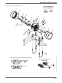
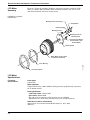
Disassembly
Procedure
Explosion can cause death or serious injury. Do not remove
the instrument cover in explosive atmospheres when the
circuit is alive.
High voltage that may be present on leads can cause
electrical shock. Make sure all power to the transmitter is off
before wiring.
NOTE
The numbers in parentheses refer to parts shown in the Illustrated Parts List,
Table 5-7, in Section 5 Specifications and Reference Data.
1. Terminal blocks for making all field wiring electrical connections are
located in a compartment identified as “Terminal Side” on the nameplate.
The sensor terminals, power supply and signal-test terminals, as well as
the zero and span adjustments are accessible by removing the Electronics
Housing Cover (2) from the terminal side. The terminals are permanently
attached to the housing and must not be removed.
2. The transmitter electronics Circuit Board Assembly (5, 6, 7) is located in a
separate compartment, identified as “Circuit Side” on the nameplate.
Make sure power is off. Then remove Circuit Side Cover (2).
NOTE
On the standard RTD input (Model 444RL), fast turn-on (Model 444RL
___B0912), and low-power (Models 444LL and LM) units, boards 5 and 6 are
integrated into one board.
3. Remove the three Circuit Board Assembly Screws (4).
4. Push equally on the zero and span adjustment pot shafts from the
terminal side. This will allow you to grasp and remove the Circuit Board
Assembly.
5. If troubleshooting is required, it is best to keep the Circuit Board
Assembly together for initial evaluation. Otherwise, the board assembly
may be disassembled by grasping the Output Board (5) around its
circumference and pulling it gently and evenly away from the other two
boards. Remove the Amplifier Board (6) in the same manner. Take care not
to bend the interconnection pins.
6. The adjustment pot shafts are sealed by two small O-rings (1D). Remove, if
necessary, by taking off the O-ring Retainer Plate (1B), which is held in
place by two small screws (1C).
7. The Nameplate (1E), Hazardous Service Certification Label (9), and
Instrument Tag (8) are held in place with Drive Screws (1F). Remove any
of these by gripping the head of the Drive Screw with pliers and carefully
turning counter-clockwise.
4-4
Maintenance and Troubleshooting
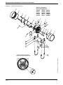
Reassembly
Procedure
Explosions can cause death or serious injury. Both
transmitter covers must be fully engaged to meet explosionproof requirements.
1. Inspect all O-rings (1D,3) and replace if necessary. Lightly grease new Orings with silicone grease to guarantee an adequate seal.
2. If the O-ring Retainer Plate (1B) has been removed, be sure the correct
side is facing outward. The resistor symbol should be visible on RTD
Transmitters, while a thermocouple symbol should be visible on
Thermocouple or Millivolt transmitters.
3. Inspect threaded connections on the housing and covers to make sure a
minimum of five undamaged threads will be fully engaged. If the threads
are shiny, apply a thin layer of molybdenum disulphide thread coating
(such as Moly-Kote) to prevent galling of the aluminum threads.
4. If the Range Board (7A) requires a Coarse Zero Jumper (7B) check to make
sure it is in the correct location for the desired temperature range. See
Table 3-1, on page 3-3 or Table 3-2, on page 3-6.
5. Orient the Range Board (7A) and Amplifier Board (6) as shown in the
Illustrated Parts List. Taking care not to bend the pins, plug the Amplifier
Board into the Range Board. Press together until all three standoffs on the
Amplifier Board rest against the Range Board.
6. Orient the Output Board (5) so its standoffs line up with the standoffs of
the Amplifier/Range Board combination. Carefully and evenly, plug the
output board into the Amplifier/Range Board. Take care not to bend the
pins. Press together until all three standoffs on the Output Board rest
against the Amplifier Board.
7. The circuit board assembly may be bench-tested, or calibrated outside the
housing through the use of Test Terminal Strips (11 and 12). See the
discussion of Calibration and Troubleshooting in this section.
8. If the circuit board assembly has been calibrated outside the housing, be
very careful to ensure the zero and span adjustment pots are not moved
while inserting the circuit board assembly into the housing.
9. Orient the circuit board assembly so the pot shafts line up with the pot
holes in the housing.
10. Insert the circuit board assembly firmly into the housing.
11. Replace the three Circuit Board Assembly Screws (4).
12. Replace the transmitter covers (2). Tighten the covers hand-tight.
Interchangeability
of Parts
Use only the procedures and new parts specifically
referenced in this manual. Unauthorized procedures or
parts can affect product performance and the output signal
used to control a process, and may render the instrument
dangerous. Direct any questions concerning these
procedures or parts to Rosemount Inc.
4-5
Rosemount Model 444 Alphaline Temperature Transmitters
Mechanical Parts
• All mechanical hardware is interchangeable among units without regard
to model numbers.
• Nameplates are interchangeable only among units that share the same
input types (i.e. RTD, Thermocouple, or Millivolt).
Electrical Parts
• Amplifier Board: Interchangeable among Models 444T and 444M.
• Output Board: 444T series (TE, TJ, TK, TT, TR, TS) and 444MV share a
common output board.
• Range Board: Interchangeable among units of the same input code (e.g.,
444RL1).
Burnout Protection
Adjustments
The Model 444T series (TE, TJ, TK, TT, TR, TS) and Model 444MV have a
resistor network that drives the output either upscale or downscale if an open
occurs in the input circuit. This option is identified in the model number. To
convert from upscale to downscale, disassemble the circuit board assembly and
remove R3 (22 meg, ¼WCC resistor) from the range board. To convert from
downscale to upscale, replace R3. If no burnout protection is desired (as in some
instances where the source has a high input impedance), remove both R2 and
R3. See Figure 3-3, on page 3-6.
Model 444RL has a jumper on the range board to select burnout protection.
Placing the jumper in the “U” position will cause the output to be driven upscale
if the RTD opens. If the jumper is in the “D” position the output will be driven
downscale. See Figure 3-1, on page 3-3. Models 444LL and 444LM have inherent
upscale burnout protection that cannot be changed. Model 444RL also has a
jumper on the range board to specify mA output at the transmitter test
terminals. Setting the jumper at the “V” position produces a 40–200 mV output
at the test terminals. Setting the jumper at the “A” position produces a
4–20 mA output at the test terminals. See Figure 3-1, on page 3-4.
REPAIR AND
WARRANTY
SERVICE
Repair and warranty service is available through the Rosemount Regional
Service Centers. Submit damage claims directly to the carrier.
RETURN OF
MATERIALS
Exposure to hazardous substances can cause death or
serious injury. If a hazardous substance is identified, a
Material Safety Data Sheet (MSDS), required by law to be
available to people exposed to specific hazardous
substances, must be included with the returned materials.
To expedite the return process, call the Rosemount North American Response
Center toll-free at 800-654-RSMT (7768). This center, available 24 hours a day,
will assist you with any needed information or materials.
The center will ask for product model and serial numbers, and will provide a
Return Material Authorization (RMA) number. The center will also ask for the
name of the process material the product was last exposed to.
The Rosemount North American Response Center will detail the additional
information and procedures necessary to return goods exposed to hazardous
substances.
4-6
Section
5
FUNCTIONAL
SPECIFICATIONS
Specifications
and Reference Data
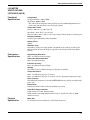
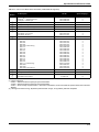
Inputs
Models 444RL, LL, and LM
100 V R0 platinum RTD per IEC 751.
Model 444T
Thermocouple types E,J,K,T,R, and S per NIST (grounded or
ungrounded).
Model 444MV
Millivolt input (grounded or ungrounded) source impedance less than
100 V.
R-numbers, specials
Special inputs other than standards, consult factory.
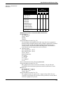
Spans
RTD
Platinum
45 to 135 °F (25 to75 °C).
125 to 380 °F (70 to 210 °C).
360 to 1080 °F (200 to 600 °C).
Copper
180 to 540 °F (100 to 300 °C).
Nickel
45 to 360 °F (25 to 200 °C).
Thermocouples
Type J, K, E, T
Type J
Type K, E
Type K
Type R, S
180 to 540 °F (100 to 300 °C).
504 to 1458 °F (280 to 810 °C).
504 to 1510 °F (280 to 840 °C).
845 to 2540 °F (470 to 1410 °C).
1467 to 3000 °F (815 to 1670 °C).
Millivolt
5 to 15 mV.
15 to 45 mV.
Outputs
Linear with temperature for RTD inputs.
Linear with millivolt input signal for thermocouple or millivolt inputs;
thermocouple and millivolt models input/output isolated to 500 V dc.
Models 444RL, T, MV
4–20 mA.
Model 444LL
0.8–3.2 V dc.
Model 444LM
1.0–5.0 V dc.
5-1
Rosemount Model 444 Alphaline Temperature Transmitters
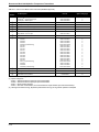
Output Limits (approximate)
Models 444RL, T, MV
Low: 3.9 mA dc.
High: 30.0 mA dc.
Model 444LL
Low: 0.1 V dc.
High: 4.2 V dc.
Model 444LM
Low: 0.125 V dc.
High: 6.2 V dc.
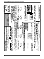
Power Supply
Models 444RL, T, and MV
12 to 45 V dc at terminals of transmitter.
Model 444LL
5 to 12 V dc (overvoltage protected to 24 V dc)
max current = 1.5 mA.
Model 444LM
8 to 12 V dc (overvoltage protected to 24 V dc)
max current = 2.0 mA.
Load Limits
Models 444RL, T, and MV
4–20 mA.
4–20 mA dc
Load (Ohms)
1650
1500
Voltage
Too Low
1000
Operating
Region
500
0
12
20
30
40
Power Supply (V dc)
Maximum Load = 50 3 (Supply Voltage – 12)
Span and Zero
Continuously adjustable, as defined in the ordering table. Adjustments are
accessible from the terminal side of the transmitter housing.
Transmitter Temperature Limits
–13 to 185 °F (–25 °C to 85 °C), transmitter operates within specifications.
–40 to 212 °F (–40 °C to 100 °C), transmitter operates without damage.
–58 to 248 °F (–50 °C to 120 °C), storage.
–13 to 149 °F (–25 °C to 65 °C), transmitter operates within specifications for
meter option.
Loss of Input
Upscale burnout indication standard for RTD inputs, downscale burnout
indication optional. Upscale burnout indication standard for thermocouple and
millivolt inputs; downscale burnout indication or no indication optional.
Turn-on Time
2 seconds. No warm-up required.
5-2
Specifications and Reference Data
PERFORMANCE
SPECIFICATIONS
Accuracy
±0.2% of calibrated span (or, for thermocouple and millivolt inputs, ±0.02
millivolts, whichever is greater). ±0.5% for copper, nickel, and isolated RTD
inputs, 0.1% for differential RTD inputs. Includes combined effects of
transmitter repeatability, hysteresis, linearity (conformity instead of linearity
for thermocouple input), and adjustment resolution. Does not include sensor
error.
Stability
±0.2% of calibrated span for six months.
Ambient Temperature Effect
Errors for 50 °F (28 °C) change in ambient temperature.
RTD Inputs
Zero: ±0.17 °C,
plus
Span: ±0.22%,
plus
Elevation/Suppression: ±0.083% of base temperature in °C.
T/C Inputs (Includes Effect of Cold Junction)
Zero: ±1.38 °C,
plus
Span: ±0.28% of span,
plus
Elevation/Suppression: ±0.11% of base
temperature in °C.
Millivolt Inputs
Zero: ±0.038 mV,
plus
Span: ±0.28% of span,
plus
Elevation/Suppression: ±0.11% of base input in mV.
Input Impedance (Thermocouple and mV Inputs)
More than 1 megohm—burnout resistors disconnected.
Power Supply Effect
±0.005% per volt.
Load Effect
No load effect other than the change in voltage supplied to the transmitter.
Vibration Effect
±0.05% of span per g to 200 Hz in any axis for 3 g’s up to 33 Hz, 2 g’s from 33 to
70 Hz and 1 g from 70 to 200 Hz.
Mounting Position Effect
None.
5-3
Rosemount Model 444 Alphaline Temperature Transmitters
PHYSICAL
SPECIFICATIONS
Materials of Construction
Electronics Housing
Low-copper aluminum. (NEMA 4X). IP 54, IP 65, IP 66.
Housing Paint
Polyurethane.
Housing O-rings
Buna-N.
Sensor and Conduit Connections
1/2-inch conduit on electronics housing. Screw terminals and integral test jacks
compatible with miniature banana plugs (Pomona 2944, 3690 or equal).
Weight
Transmitter: 3 lb (1.4 kg).
Transmitter with mounting bracket: 4 lb (1.8 kg).
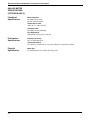
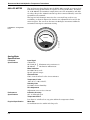
Hazardous Location Certifications
Factory Mutual (FM) Approvals
E5 Explosion Proof: Class I, Division 1, Groups B, C, and D. Dust Ignition
Proof: Class II, Division 1, Groups E, F, and G; Class III, Division 1
hazardous locations. Indoor and outdoor use. NEMA Enclosure Type 4X.
Refer to Factory Mutual Explosion Proof Drawing 00444-0261.
I5 Intrinsic Safety: Class I, Division 1, Groups A, B, C, and D; Class II,
Division 1, Groups E, F, and G; Class III, Division 1 hazardous locations;
Intrinsically safe system only when applying Table 5-1 entity parameters.
Nonincendive: Class I, Division 2, Groups A, B, C, and D; Indoor and
outdoor use. NEMA Enclosure Type 4X.
Refer to Factory Mutual Intrinsic Safety Drawing 01151-0214.
K5 Combination of E5 and I5.
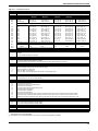
TABLE 5-1. FM Entity
Parameters.
Model 444
Parameters
FM Approved for
Class I, II, III,
Division 1, Groups
Associated
Equipment
Parameters
VMAX = 40 V
IMAX = 165 mA
Ci = 0.044µF
Li = 0
VOC or VT ≤ 40 V
ISC or IT ≤ 165 mA
CA > 0.044µF
LA > 0
VMAX = 40 V
IMAX = 225 mA
Ci = 0.044µF
Li = 0
VOC or VT ≤ 40 V
ISC or IT ≤ 225 mA
CA > 0.044µF
LA > 0
A
B
C thru G
•
•
•
NA
NA
•
Canadian Standards Association (CSA) Approvals
E6 Explosion Proof: Class I, Division 1, Groups C and D; Dust-ignitionproof
Class II, Division 1, Groups E, F, and G; Class III, Division 1 hazardous
locations; Suitable for Class I, Division 2, Groups A, B, C, and D; CSA
Enclosure Type 4X.
I6 Intrinsic Safety: Class I, Division 1, Groups A, B, C, and D. Intrinsically
safe system only when applying Table 5-2 parametric parameters.
Temperature code T2D. CSA Enclosure Type 4X.
Refer to CSA Intrinsic Safety Drawing 00444-0034.
C6 Combination of E6 and I6.
5-4
Specifications and Reference Data
TABLE 5-2. CSA Parametric
Parameters.
CSA Approved for
Class I,
Division 1 Groups
Barrier Manufacturer/Model
A
B
C
D
•
•
•
•
Foxboro Converters
2AI-I2V-CGB
2AI-I3V-CGB
2AS-I2I-CGB
2AS-I3I-CGB
3AD-I3IA CS-E/CGB-A
3A2-I2D CS-E/CGB-A,
3A2-I3D CS-E/CGB-A
3A4-I2DA CS-E/CGB-A
3F4-I2DA1 CS-E/CGB-A
NA
•
•
•
Any CSA approved zener barrier
≤30 V, ≥150V
NA
NA
•
•
Any CSA approved zener barrier
≤30 V, ≥330 V or
≤28 V, ≥300 V or
≤22 V, ≥180 V
Standards Association of Australia (SAA) Certifications
E7 Flameproof:
Ex d IIB+H2 T6
Class I, Zone 1.
DIP T6
Class II.
Special Conditions for Safe Use (“X”):
For transmitters having NPT or PG cable entry thread, an appropriate
flameproof thread adaptor shall be used to facilitate application of certified
flameproof cable glands. Only SAA-certified flameproof temperature
sensors shall be used with the Model 444 Temperature Transmitter if
fitted directly into the tapped entry of the enclosure.
I7 Intrinsic Safety:
Ex ia IIC T6 (Tamb = 40 °C)
Ex ia IIC T5 (Tamb = 70 °C)
Class I, Zone 0
Entity Parameters:
Ui = 30 V
Ii = 200 mA
Pi = 1.0 W
Ci = 0.024 mF
Li = 0
Refer to SAA Intrinsic Safety Drawing 00444-0264.
Special Conditions for Safe Use (“X”):
The equipment has been assessed to the “Entity” concept and upon
installation the barrier/entity parameters must be taken into account.
N7 Type “n”:
Ex n IIC T6 (Tamb = 40 °C)
Ex n IIC T5 (Tamb = 70 °C)
Class I, Zone 2
Special Conditions for Safe Use (“X”):
The equipment must be connected to a supply voltage which does not
exceed the rated voltage. The enclosure end caps must be correctly fitted
while the equipment is powered.
5-5
Rosemount Model 444 Alphaline Temperature Transmitters
Centro Elettrotecnico Sperimentale Italiano (CESI/CENELEC) Certifications
E8 Flameproof:
EEx d IIC T6
I8 Intrinsic Safety:
Model 444RL
EEx ia IIC T6 (Tamb = 40 °C) [Pi = 0.75 W]
EEx ia IIC T5 (Tamb = 55 °C) [Pi = 1.0 W]
EEx ia IIC T4 (Tamb = 80 °C) [Pi = 1.0 W]
Model 444T_ & MV
EEx ib IIB T6 (Tamb = 40 °C) [Pi = 0.75 W]
EEx ib IIB T5 (Tamb = 55 °C) [Pi = 1.0 W]
EEx ib IIB T4 (Tamb = 80 °C) [Pi = 1.0 W]
Entity Parameters:
Vi = 30 V dc
Ii = 200 mA
Pi = 0.75 W (T6)
Pi = 1.0 W (T5)
Pi = 1.0 W (T4)
Ci = 0.024 mF (Model 444RL)
Ci = 0.006 mF (Model 444T_ & MV)
Li = 0.
Special Conditions for Safe Use (“X”):
If the temperature sensor connected to the input circuit does not tolerate
an alternating tension of 500V for 60 seconds, the certified transducers
must be powered by galvanically-insulated equipment. Model 444RL
temperature transducers must be connected to associated electronic
equipment certified to EN 50.014/EN 50.020 standards.
British Approvals Service for Electrical Equipment Flammable Atmospheres
(BASEEFA) Type N Certification
N1 Ex N II T5
Maximum Voltage: 35 V dc
Maximum Current: 30 mA dc
An appropriate stainless steel tag will be supplied according to the certification
option selected.
5-6
Specifications and Reference Data
LCD METER
SPECIFICATIONS
(OPTIONS D AND E)
Functional
Specifications
Configuration
4 mA point limits: –999 to 1000.
Span limits: 0200 to 9999.
The sum of the 4 mA point and span must not exceed 9999. Adjustments are
made using non-interactive zero and span buttons.
Temperature Limits
Storage: –40 to 85 °C (–40 to 185 °F).
Operating: –20 to 70 °C (–4 to 158 °F).
Between –40 to –20 °C (–40 to –4 °F) loop is intact and the meter is not damaged.
Humidity Limitation
0 to 95% non-condensing relative humidity.
Update Period
750 ms.
Response Time
Responds to changes in input within a maximum of two update periods. If the
filter is activated, then the display responds to the change within nine update
periods.
Performance
Specifications
Digital Display Resolution
0.05% of calibrated range ±1 digit.
Analog Bar Graph Resolution
0.05% of calibrated range.
Indication Accuracy
0.25% of calibrated range ±1 digit.
Stability
Over Time: 0.1% of calibrated range ±1 digit per six months.
Temperature Effect
0.01% of calibrated range per °C on zero.
0.02% of calibrated range per °C on span over the operating temperature range.
Power Interrupt
All calibration constants are stored in EEPROM memory and are not affected by
power loss.
Failure Mode
LCD meter failure will not affect transmitter operation.
Under/Over Range Indication
Input current < 3.5 mA: Display blank.
Input current > 22.0 mA: Display flashes 112.5% of full scale value or 9999,
whichever is less.
Physical
Specification
Meter Size
2¼-inch diameter face with four, ½-inch high characters.
5-7
Rosemount Model 444 Alphaline Temperature Transmitters
ANALOG METER
SPECIFICATIONS
(OPTIONS B AND C)
Functional
Specifications
Meter Indication
0 to 100% linear scale.
Special optional ranges.
Temperature Limits
–40 to 65 °C (–40 to 150 °F).
Humidity Limits
0 to 100% relative humidity.
Zero Adjustment
Adjustment screw on face of meter.
Performance
Specifications
Indication Accuracy
±2% of calibrated span.
Temperature Effect
Less than 2% of full scale at any point within the temperature limits.
Physical
Specification
5-8
Meter Size
2¼-inch diameter face with 2-inch long scale.
Specifications and Reference Data
TABLE 5-3. 444 Model Structure.
Model
444
Code
RL1
RL2
RL3
Product Description
Alphaline Temperature Transmitter
Temperature Span
Minimum
Maximum
Input Type(1)
45 °F (25 °C)
125 °F (70 °C)
360 °F (200 °C)
Platinum RTD
100 V R0
linearized output
135 °F (75 °C)
380 °F (210 °C)
1080 °F (600 °C)
RL9
Special Input, Range or Accuracy (minimum span 3 V)
TJ1
TJ2
TK1
TK2
TK3
TE1
TE2
TT1
TR1
TS1
Thermocouple
Type J
Type J
Type K
Type K
Type K
Type E
Type E
Type T
Type R
Type S
T_9
Special Range or Accuracy (minimum span 3 mV, maximum span 100 mV)
MV1
MV2
MV9
Code
U
D
N
Code
1
2
3
Code
A
B
C
D
E
Code
1
2
Code
NA
E5
I5
E6
I6
E7
I7
N7
E8
I8
N1
Code
Q4
A1
A2
Code
RXXXX
180 °F (100 °C)
504 °F (280 °C)
180 °F (100 °C)
504 °F (280 °C)
845 °F (470 °C)
180 °F (100 °C)
504 °F (280 °C)
180 °F (100 °C)
1467 °F (815 °C)
1467 °F (815 °C)
Millivolt
Millivolt
540 °F (300 °C)
1458 °F (810 °C)
540 °F (300 °C)
1510 °F (840 °C)
2540 °F (1410 °C)
540 °F (300 °C)
1510 °F (840 °C)
540 °F (300 °C)
3000 °F (1670 °C)
3000 °F (1670 °C)
5 mV
15 mV
15 mV
45 mV
Base Temperature
Minimum
Maximum
–58 °F (–50 °C)
–58 °F (–50 °C)
–58 °F (–50 °C)
300 °F (150 °C)
300 °F (150 °C)
300 °F (150 °C)
–58 °F (–50 °C)
–58 °F (–50 °C)
–58 °F (–50 °C)
–58 °F (–50 °C)
–58 °F (–50 °C)
–58 °F (–50 °C)
–58 °F (–50 °C)
–58 °F (–50 °C)
0 °F (–18 °C)
0 °F (–18 °C)
300 °F (150 °C)
930 °F (500 °C)
300 °F (150 °C)
930 °F (500 °C)
930 °F (500 °C)
300 °F (150 °C)
930 °F (500 °C)
300 °F (150 °C)
1500 °F (815 °C)
1500 °F (815 °C)
–2 mV
–2 mV
Upper Range Limit
435 °F (225 °C)
680 °F (360 °C)
1380 °F (750 °C)
840 °F (450 °C)
1400 °F (760 °C)
840 °F (450 °C)
2440 °F (1340 °C)
2500 °F (1370 °C)
840 °F (450 °C)
1830 °F (1000 °C)
750 °F (400 °C)
3200 °F (1760 °C)
3200 °F (1760 °C)
8 mV
20mV
23 mV
65 mV
Special Range or Accuracy (minimum span 3 mV, maximum span 100 mV)
Loss of Input Indication
Upscale (standard for all input types)
Downscale
None (not available for platinum RTD inputs)
Calibration
Trim to IEC 751 Class B (RTD) or NIST Curve (thermocouple)
Trim to Specific Model 68/78/88 Calibration Schedule
Trim to Other Nominal Curve (customer must specify separately) (Note: Millivolt input must use Code 3.)
Meter Options
None
Integral Analog Meter, Special Scale (same as calibrated range)
Integral Analog Meter, 0–100% Scale
Integral LCD Meter, 0–100% Scale(2)
Integral LCD Meter, Special Scale (specify range, mode, and engineering units)(1)
Mounting Bracket
None
Mounting Bracket for 2-inch Pipe or Surface Mounting
Hazardous Area Certifications
No Certification Required
FM Explosion-Proof Approval
FM Intrinsic Safety and Non-incendive Approval
CSA Explosion-Proof Approval
CSA Intrinsic Safety Approval (444RL and 444T only)
SAA Explosion-Proof Certification
SAA Intrinsic Safety Certification
SAA Non-incendive Certification
CESI Explosion-Proof Certification (When ordering a transmitter with this option, place a W before the model number: W444.)
CESI Intrinsic Safety Certification (When ordering a transmitter with this option, place a W before the model number: W444.)
BASEEFA Non-incendive Certification (When ordering a transmitter with this option, place a T before the model number: T444.)
Options
2-Point Calibration Certificate
One (1) ½ NPT to M20 (CM 20) SST Thread Adapter
One (1) ½ NPT to M20 (CM 20) SST Thread Adapter
Special
Unique Range (use with RL9, T_9, and MV9 inputs)
Typical Model Number:
0444
RL3
U
1
A
2
E5
Q4
(1) Refer to Temperature Sensors, Assemblies , and Accessories Product Data Sheet, Rosemount pub. no. 00813-0100-2654 for information
about Rosemount sensor assemblies.
(2) LCD Meters are only available with RL1, RL2, or RL3. (may be reconfigured in the field.)
5-9
Rosemount Model 444 Alphaline Temperature Transmitters
TABLE 5-4. 444RL Fast Turn-on Model Structure.
Model
444
Code
RL1
RL2
RL3
Code
U
Code
1
2
3
Code
A
B
C
Code
1
2
Code
NA
E5
E6
I6
Code
Q4
A1
A2
Product Description
Alphaline Fast Turn-On Temperature Transmitter
Temperature Span
Minimum
Maximum
Input Type(1)
Platinum RTD
100 V R0
linearized output
linearized output
45 °F (25 °C)
125 °F (70 °C)
360 °F (200 °C)
135 °F (75 °C)
380 °F (210 °C)
1080 °F (600 °C)
Base Temperature (4mA Point)
Minimum
Maximum
Upper Range
Limit
–58 °F (–50 °C)
–58 °F (–50 °C)
–58 °F (–50 °C)
435 °F (225 °C)
680 °F (360 °C)
1380 °F (750 °C)
300 °F (150 °C)
300 °F (150 °C)
300 °F (150 °C)
Loss of Input Indication
Upscale (standard for all input types)
Calibration
Trim to IEC 751 Curve (RTD)
Trim to Specific Model 68/78/88 Calibration Schedule
Trim to Other Nominal Curve (customer must specify separately)
Meter Options
None
Integral Analog Meter, Special Scale (must specify range, mode, and engineering units)
Integral Analog Meter, 0–100% Scale
Mounting Bracket
None
Mounting Bracket for 2-inch Pipe or Surface Mounting
Hazardous Area Certifications
No Certification Required
FM Explosion-Proof Approval
CSA Explosion-Proof Approval
CSA Intrinsic Safety Approval
Options
2-Point Calibration Certificate
One (1) ½ NPT to M20 (CM 20) SST Thread Adapter
One (1) ½ NPT to M20 (CM 20) SST Thread Adapter
Code
Special
B0912
Fast Turn-on Electronics
Typical Model Number:
0444
RL3
U
1
A
2
NA
B0912
(1) Refer to Temperature Sensors, Assemblies , and Accessories Product Data Sheet, Rosemount pub. no. 00813-0100-2654 for information
about Rosemount sensor assemblies.
5-10
Specifications and Reference Data
TABLE 5-5. 444LL, LM Model Structure.
Model
444
Code
LL1
LM1
Code
U
Code
1
2
Code
A
Code
1
2
Code
NA
E5
E6
I6
Product Description
Alphaline Low-Power Temperature Transmitter
Temperature Span
Minimum
Maximum
Input Type(1)
Platinum RTD
100 V R0
Linearized Output
75 °F (42 °C)
75 °F (42 °C)
Base Temperature (4mA Point)
Minimum
Maximum
150 °F (83 °C)
150 °F (83 °C)
–25 °F (–32 °C)
–25 °F (–32 °C)
50 °F (10 °C)
50 °F (10 °C)
Loss of Input Indication
Upscale
Calibration
Trim to IEC 751 Curve (RTD)
Trim to Specific Model 68/78/88 Calibration Schedule
Meter Options
None
Mounting Bracket
None
Mounting Bracket for 2-inch Pipe or Surface Mounting
Options
No Certification Required
FM Explosion-Proof Approval
CSA Explosion-Proof Approval
CSA Intrinsic Safety Approval (444RL and 444T only)
Typical Model Number:
0444
LM1
U
1
A
2
E5
(1) Refer to Temperature Sensors, Assemblies , and Accessories Product Data Sheet, Rosemount pub. no. 00813-0100-2654 for information
about Rosemount sensor assemblies.
TABLE 5-6. Meter Kits.
Part Description
40–200 mV Analog Meter Kit(2)
40–200 mV Analog Meter Kit (CENELEC and I.S. approved) (2)
40–200 mV Analog Meter
40–200 mV Analog Meter (CENELEC approved)
4–20 mA LCD Meter Kit (2) (3)
4–20 mA LCD Meter
Mounting Hardware and Cover Kit
Mounting Hardware Kit
Cover Assembly
Meter with Special Scale(4)
(1)
(2)
(3)
(4)
Part Number
Spares Category(1)
00444-0194-0001
00444-0194-0005
01151-0687-0003
01151-0744-0003
00444-0194-0004
01151-1300-1000
00444-0194-0002
00444-0194-0003
01151-2610-0001
scale: XX to XX
C
C
C
C
C
C
C
C
C
C
Normally, no spare parts required for C classification.
Meter kit includes meter, mounting hardware, and cover assembly.
LCD Meters are only available with RL1, RL2, and RL3 (may be reconfigured in the field).
For Special Scale Meters, order appropriate meter and indicate special scale desired. Mounting hardware and cover
assembly must be ordered separately
5-11
Rosemount Model 444 Alphaline Temperature Transmitters
TABLE 5-7. Standard Parts List.
Item
Number
1
2
j
3
j
1
D
j
4
j
3
j
5
j
6
j
j
7A
j
7A
j
7A
j
7B
8
j
9
j
10
11
j
12
j
Part Number
Spares
Category(1)
Housing Kit—RTD Input
Housing Kit—Thermocouple Input
Housing kit—Millivolt Input
Electronics housing kit consists of:
1A )
1 each electronics housing (item j
1B )
1 each O-ring retainer plate (item j
1C )
2 each 6–32 3 3/16 retainer plate screws (item j
1D )
2 each pot O-rings (item j
1E )
1 each nameplate (item j
1F )
2 each #4–40 3 3/16 screws (item j
00444-0028-0001
00444-0028-0002
00444-0028-0003
C
C
C
ALL
Housing Cover—Quantity One
90032-0240-0003
C
ALL
Housing Cover O-ring
01151-0033-0003
C
ALL
Adjustment Potentiometer O-ring (pkg. of 12)
00444-0030-0001
B
ALL
Electronics Assembly Screws, 6–32 317/8 (pkg. of 12)
00444-0031-0001
C
ALL
Cover O-rings. (pkg. of 12)
00444-0030-0001
B
ALL
A/O Board—RTD Input (2 board set, Figure 5-1)
Output Board—T/C, mV Input (3 board set, Figure 5-2)
00444-0228-0001
00444-0015-0001
A
A
ALL
Amplifier Board—All Inputs (3 board set, Figure 5-2)
00444-0007-0003
A
444R
Range Board—RTD Inputs
25 to 75 °C Span (Input Code RL1)
70 to 210 °C Span (Input Code RL2)
200 to 600 °C Span (Input Code RL3)
Special Range RL9 (requires 3 board set – consult factory)
00444-0221-0001
00444-0221-0002
00444-0221-0003
00444-0003-XXXX
A
A
A
A
Range Board—Thermocouple Inputs
Type J, 100 to 300 °C Span (Input Code TJ1)
Type J, 280 to 840 °C Span (Input Code TJ2)
Type K, 100 to 300 °C Span (Input Code TK1)
Type K, 280 to 840 °C Span (Input Code TK2)
Type K, 470 to 1410 °C Span (Input Code TK3)
Type E, 100 to 300 °C Span (Input Code TE1)(2)
Type E, 280 to 840 °C Span (Input Code TE2)
Type T, 100 to 300 °C Span (Input Code TT1)
Type R, 815 to 1670 °C Span (Input Code TR1)
Type S, 815 to 1670 °C Span (Input Code TS1)
Special Range T-9 Kit (consult factory)
00444-0262-0002
00444-0262-0006
00444-0262-0003
00444-0262-0007
00444-0262-0008
00444-0262-0001
00444-0262-0005
00444-0262-0004
00444-0262-0009
00444-0262-0010
00444-0013-XXXX
A
A
A
A
A
A
A
A
A
A
A
Range Board—Millivolt Inputs
5 to 15 mV (Input Code MV1)
15 to 45 °C Span (Input Code MV2)
Special Range MV9 (consult factory)
00444-0023-0001
00444-0023-0002
00444-0023-XXXX
A
A
A
444R
Range Board Zero Jumpers (pkg. of 12)
00444-0036-0001
A
ALL
Instrument Tag (optional)
01151-0148
C
ALL
Certification Label
–
C
ALL
Mounting Bracket Kit
1 each mounting bracket (item 10A )
4 each ¼–20 3 ½ bolts(item 10B )
2 each U-bolts (item 10C )
4 each ¼ washers (item 10D )
4 each 5/16 –18 nuts (item 10E )
2 each washer plates (item 10F )
00444-0022-0001
C
ALL
Terminal Block, Three-position
Terminal Block, Four-position
C10448-0106
C10448-0109
D
D
Model
444R
444T
444M
444T
444M
Part Description
(1) Spares Categories (2) Thermocouple Range Board Kit Consists of:
Code A – Recommended 1 spare part per 25 transmitters. 1 each T/C Range Board.
Code B – Recommended 1 spare part per 50 transmitters. 1 each External CJC Block.
Code C – None normally required.
Code D – Not used on transmitters, but recommended for repair actiivities.
5-12
Specifications and Reference Data
TABLE 5-8. Parts List for Model W444 Transmitter (CESI/CENELEC Approval).
Item
Number
Part No.
Spares Category(1)
Housing Kit(2) — RTD Input
Housing Kit(2) — Thermocouple Input
Housing kit(2) — Millivolt Input
00444-0028-0001
00444-0028-0002
00444-0028-0003
C
C
C
Housing Cover—Quantity One
90032-0240-0003
C
Housing Cover O-rings
01151-0033-0003
B
Adjustment Potentiometer O-rings
00444-0030-0001
B
Electronics Assembly Screws
00444-0031-0001
C
A/O Board—RTD Input
Output Board—T/C, mV Input
Output Board—RD Input
00444-0228-0001
00444-0015-0002
00444-0111-0001
A
A
A
Amplifier Board
00444-0007-0003
A
Range Board
W444 RL1
W444 RL2
W444 RL3
W444 RL9 (consult factory)
W444 TJ1
W444 TJ2
W444 TK1
W444 TK2
W444 TK3
W444 TE1
W444 TE2
W444 TT1
W444 TR1
W444 TS1
W444 T_9 (consult factory)
W444 MV1
W444 MV2
W444 MV9 (consult factory)
00444-0221-0001
00444-0221-0002
00444-0221-0003
00444-0003-XXXX
00444-0262-0002
00444-0262-0006
00444-0262-0003
00444-0262-0007
00444-0262-0008
00444-0262-0001
00444-0262-0005
00444-0262-0004
00444-0262-0009
00444-0262-0010
00444-0013-XXXX
00444-0023-0001
00444-0023-0002
00444-0023-XXXX
A
A
A
A
A
A
A
A
A
A
A
A
A
A
A
A
A
A
j
7B
Range Board Zero Jumpers
00444-0036-0001
A
10
Mounting Bracket Kit
00444-0022-0001
C
11
j
12
j
Terminal Block, Three-position
Terminal Block, Four-position
C10448-0106
C10448-0109
D
D
1
2
j
3
j
1
D
j
4
j
5
j
6
j
j
7A
Part Description
(1) Spares Categories
Code A – Recommended one spare part per 25 transmitters.
Code B – Recommended one spare part per 50 transmitters.
Code C – None normally required.Code D – Not used on transmitters, but recommended for repair activities (see Instruction
Manual).
(2) Housing kit includes housing, adjustment potentionmeter O-rings, O-ring retainer plate and nameplate.
5-13
Rosemount Model 444 Alphaline Temperature Transmitters
TABLE 5-9. Parts List for Model T444 Transmitter (BASEEFA Approval).
Item
Number
1
2
j
3
j
1
D
j
4
j
5
j
6
j
j
7A
Part No.
Spares Category(1)
Housing Kit(2)—RTD Input
Housing Kit(2)—Thermocouple Input
Housing kit(2)—Millivolt Input
00444-0028-0001
00444-0028-0002
00444-0028-0003
C
C
C
Housing Cover—Quantity One
90032-0240-0003
C
Part Description
Housing Cover O-rings
01151-0033-0003
B
Adjustment Potentiometer O-rings
00444-0030-0001
B
Electronics Assembly Screws
00444-0031-0001
C
A/O Board—RTD Input
Output Board—T/C, mV Input
00444-0228-0001
00444-0015-0001
A
Amplifier Board
00444-0007-0003
A
Range Boards
T444 RL1
T444 RL2
T444 RL3
T444 RL9 (consult factory)
T444 TE1
T444 TJ1
T444 TK1
T444 TT1
T444 TE2
T444 TJ2
T444 TK2
T444 TK3
T444 TR1
T444 TS1
T444 T_9 (consult factory)
T444 MV1
T444 MV2
T444 MV9 (consult factory)
00444-0136-0001
00444-0136-0002
00444-0136-0003
00444-0136-XXXX
00444-0273-0001
00444-0273-0002
00444-0273-0003
00444-0273-0004
00444-0273-0005
00444-0273-0006
00444-0273-0007
00444-0273-0008
00444-0273-0009
00444-0273-0010
00444-0138-XXXX
00444-0139-0001
00444-0139-0002
00444-0139-XXXX
A
A
A
A
A
A
A
A
A
A
A
A
A
A
A
A
A
A
j
7B
Range Board Zero Jumpers
00444-0036-0001
A
10
Mounting Bracket Kit
00444-0022-0001
C
11
j
12
j
Terminal Block, Three-position
Terminal Block, Four-position
C10448-0106
C10448-0109
D
D
For meter information, see page 7.
(1) Spares Categories
Code A – Recommended one spare part per 25 transmitters.
Code B – Recommended one spare part per 50 transmitters.
Code C – None normally required.
Code D – Not used on transmitters, but recommended for repair activities (see Instruction Manual).
(2) Housing kit includes housing, adjustment potentiometer O-rings, O-ring retainer plate and nameplate.
5-14
Specifications and Reference Data
TABLE 5-10. Parts List for Model 444 RL Fast Turn On Transmitter (RTD Input).
Item
Number
1
2
j
3
j
1D
j
4
j
5
j
j
7A
Part No.
Spares Category(1)
Housing Kit(2)
00444-0028-0001
C
Housing Cover—Quantity One
90032-0240-0003
C
Part Description
Housing Cover O-rings
01151-0033-0003
B
Adjustment Potentiometer O-rings
00444-0030-0001
B
Electronics Assembly Screws
00444-0031-0001
C
Output Board 444 RL B0912
00444-0126-0001
A
Range Boards
RL1 B0912
RL2 B0912
RL3 B0912
00444-0221-0011
00444-0221-0012
00444-0221-0013
A
A
A
j
7B
Range Board Zero Jumpers
00444-0036-0001
A
10
Mounting Bracket Kit
00444-0022-0001
C
11
j
12
j
Terminal Block, Three-position
Terminal Block, Four-position
C104480106
C104480109
D
D
For meter information, see page 7.
(1) Spares Categories
Code A – Recommended one spare part per 25 transmitters.
Code B – Recommended one spare part per 50 transmitters.
Code C – None normally required.
Code D – Not used on transmitters, but recommended for repair activities (see Instruction Manual).
(2) Housing kit includes housing, adjustment potentiometer O-rings, O-ring retainer plate and nameplate.
TABLE 5-11. Parts List for Model 444 LL, 444 LM Low Power Transmitter (RTD Input).
Item
Number
1
j
3
j
1
D
j
4
j
5
j
2
Part No.
Spares Category(1)
Housing Kit(2)
00444-0028-0005
C
Housing Cover—Quantity One
90032-0240-0003
C
Housing Cover O-rings
01151-0033-0003
B
Part Description
Adjustment Potentiometer O-rings
00444-0030-0001
B
Electronics Assembly Screws
00444-0031-0001
C
Output Board 444 LL
Output Board 444 LM
00444-0159-0001
00444-0159-0002
A
A
Range Boards
444 LL
444 LM
00444-0157-0001
00444-0157-0002
A
A
j
7B
Range Board Zero Jumpers
00444-0036-0001
C
10
Mounting Bracket Kit
00444-0022-0001
C
11
j
12
j
Terminal Block, Three-position
Terminal Block, Four-position
C104480106
C104480109
D
D
j
7A
No meter available.
(1) Spares Categories
Code A – Recommended one spare part per 25 transmitters.
Code B – Recommended one spare part per 50 transmitters.
Code C – None normally required.
Code D – Not used on transmitters, but recommended for repair activities (see Instruction Manual).
(2) Housing kit includes housing, adjustment potentiometer O-rings, O-ring retainer plate and nameplate.
5-15
Rosemount Model 444 Alphaline Temperature Transmitters
TABLE 5-12. Parts List for Model 444 Increased Accuracy or Special Range Transmitters.
Item
Number
1
2
j
3
j
1
D
j
4
j
5
j
6
j
j
7A
Part No.
Spares Category(1)
Housing Kit(2)—RTD Input
Housing Kit(2)—Thermocouple Input
Housing kit(2)—Millivolt Input
00444-0028-0001
00444-0028-0002
00444-0028-0003
C
C
C
Housing Cover—Quantity One
90032-0240-0003
C
Part Description
Housing Cover O-rings
01151-0033-0003
B
Adjustment Potentiometer O-rings
00444-0030-0001
B
Electronics Assembly Screws
00444-0031-0001
C
Output Board RL9
Output Board T_9
Output Board MV9
00444-0005-0001
00444-0015-0001
00444-0015-0001
A
A
A
Amplifier Board
00444-0007-0003
A
Range Boards
RL9 (consult factory)
T_9 (consult factory)
MV9 (consult factory)
00444-0003-XXXX
00444-0013-XXXX
00444-0023-XXXX
A
A
A
j
7B
Range Board Zero Jumpers
00444-0036-0001
C
10
Mounting Bracket Kit
00444-0022-0001
C
11
j
12
j
Terminal Block, Three-position
Terminal Block, Four-position
C10448-0106
C10448-0109
D
D
For meter information, see below.
(1) Spares Categories
Code A – Recommended one spare part per 25 transmitters.
Code B – Recommended one spare part per 50 transmitters.
Code C – None normally required.
Code D – Not used on transmitters, but recommended for repair activities.
(2) Housing kit includes housing, adjustment potentiometer O-rings, O-ring retainer plate and nameplate.
5-16
Specifications and Reference Data
FIGURE 5-1. Transmitter Exploded View 1.
View Corresponds to
the Following Models:
2
j
444RL1
444RL2
444RL3
3
j
4
j
444LM1
444LL1
5
j
j
7A
8
j
9
j
j
1A
j
7B
1D
1B
j
j
1F
j
1C
j
3
j
2
j
1E
j
10E
10F
10D
10A
10B
444-1151C02A, 0071A01A, 0071B01A, 1151H02A
10C
Detail of Item 1B. O-Ring Retainer Plate Wiring Diagrams
Reversible
Thermocouple
or Millivolt
Side
Accessory Terminal Blocks For
Bench Testing
Models 444T, MV
RTD Side
Models 444RL, LL, LM
5-17
Rosemount Model 444 Alphaline Temperature Transmitters
FIGURE 5-2. Transmitter Exploded View 2.
View Corresponds to
the Following Models:
j
2
444RL9
444TJ1
444TJ2
444TK1
444TK2
3
j
4
j
5
j
444TK3
444TE1
444TE2
444TT1
444T_9
444TR1
444TS1
444MV1
444MV2
444MV9
6
j
j
7A
8
j
9
j
1A
j
j
7B
1D
j
1F
j
1B
j
1C
j
3
j
2
j
1E
j
10E
10F
10D
10A
10B
10C
3044-0X68C01A, 444-1151B02A, 0236D01A
Detail of Remote Cold Junction
Compensation Sensor. (Model 444T)
5-18
Section
6
Options
The mounting bracket option provides auxiliary configurations for
mounting the Model 444 transmitter. With this option you can either
mount the transmitter to a 2-inch pipe or a suitable flat panel. The
bracket is constructed of carbon steel with carbon steel U-bolts. See
Figure 6-1 for an exploded view of the Model 444 with a mounting
bracket in both configurations.
MOUNTING BRACKET
FIGURE 6-1. Model 444 with
Optional Mounting Bracket.
PANEL OR SURFACE MOUNTING
PIPESTAND MOUNTING
Transmitter can be Rotated 90°
5
/16 -inch Bolts
(four required,
not furnished)
2.81 (81)
Mounting Bracket
Hole for
/16 -inch
Bolts
(four
places)
5
Clearance Hole
for ¼-inch Bolt
(eight places)
444-1151G, 1151F04A
¼–20 3½-inch
Bolt (4)
5
/16 –18 U-bolt for
2-inch Pipe (2)
5.00 (127)
NOTE
Dimensions are in inches (millimeters).
6-1
Rosemount Model 444 Alphaline Temperature Transmitters
LCD / ANALOG
METER
The LCD and analog meters provide local indication of the transmitter output.
Both meters attach easily to the terminal side of the transmitter.
LCD METER
The Rosemount® LCD meter plugs directly into the Model 444 to provide a
highly accurate digital display of the process variable. The meter adds no voltage
drop in the 4–20 mA current loop when connected directly across the transmitter
test terminals.
Configuration
Configure the LCD meter to meet specific requirements by using the left and
right calibration buttons located on the meter face as shown in Figure 6-2. The
analog bar graph is also shown in Figure 6-2. The 20-segment bar graph is
factory calibrated and represents
4–20 mA directly.
FIGURE 6-2. LCD Meter.
.
Left Configuration
Button
Retaining
Ring
Right Configuration
Button
LCD-001AB
Analog
Bar Graph
No calibration equipment is required to configure the LCD meter, but between 4
and 20 mA must exist in the loop in order for the meter to operate. The actual
value of the current is not significant. In addition, meter configuration does not
affect the transmitter/loop current. Use the following meter configuration
procedure to properly configure the LCD meter.
Remove the Cover
1. Unscrew the retaining ring shown in Figure 6-2 and lift the transparent
cover off of the housing.
NOTE
The LCD meter time-out is approximately 16 seconds. If keys are not pressed
within this period, the indicator reverts to reading the current signal.
6-2
Options
Position the Decimal
Point and Select the
Meter Function
2. Press the left and right configuration buttons simultaneously and release
them immediately.
3. To move the decimal point to the desired location, press the left
configuration button. Note that the decimal point wraps around.
4. To scroll through the mode options, press the right configuration button
repeatedly until the desired mode is displayed. See Table 6-1.
TABLE 6-1. LCD Meter Modes.
Options
Relationship between Input Signal and Digital Display
L in
Linear
L inF
Srt
SrtF
Linear with five-second filter
Square root
Square root with five-second filter
Square root function only relates to the digital display.
The bar graph output remains linear with the current signal.
Square root response
The digital display will be proportional to the square root of the input current where 4 mA=0
and 20 mA=1.0, scaled per the calibration procedure. The transition point from linear to
square root is at 25% of full scale flow.
Filter response operates upon “present input” and “input received in the previous five second
interval” in the following manner:
Display = (0.75 3 previous input) + (0.25 3 present input)
This relationship is maintained provided that the previous reading minus the present reading is
less than 25% of full scale.
Store the Information
5. Press both configuration buttons simultaneously for two seconds. Note
that the meter displays “----” for approximately 7.5 seconds while the
information is being stored.
Set the Display
Equivalent
to a 4 mA Signal
6. Press the left button for two seconds.
7. To decrement the display numbers, press the left configuration button and
to increment the numbers, press the right configuration button. Set the
numbers between –999 and 1000.
8. To store the information, press both configuration buttons simultaneously
for two seconds.
Set the Display
Equivalent
to a 20 mA Signal
9. Press the right button for two seconds.
10. To decrement the display numbers, press the left configuration button on
the display and to increment the numbers, press the right configuration
button. Set the numbers between –999 and 9999. The sum of the 4 mA
point and the span must not exceed 9999.
11. To store the information, press both configuration buttons simultaneously
for two seconds. The LCD meter is now configured.
Replace the Cover
12. Make sure the rubber gasket is seated properly, replace the transparent
cover, and replace the retaining ring.
6-3
Rosemount Model 444 Alphaline Temperature Transmitters
LCD Meter
Assembly
Figure 6-3 shows the mounting hardware required to properly install the LCD
meter on a Model 444 transmitter. This mounting hardware may also be used
with the Rosemount universal (analog) meter.
FIGURE 6-3. LCD Meter
Exploded View
Mounting Screw into Housing
Strap Washer
Retaining Straps
Mounting Screws
Mounting Screw into
Mounting Plate
Terminal Screws (Mount
into Transmitter “Test”
Terminal Block)
Mounting Plate
Meter (Meter may be rotated
in 90 degree increments)
Cover Foam Spacer
LCD Meter
Specifications
Functional
Specifications
Input Signal
4–20 mA dc.
Meter Indication
4-digit LCD showing –999 to 9999. A 20-segment bar graph directly represents
the 4–20 mA current.
Scaling/Calibration
4 mA Point Limits: –999 to 1000.
Span limits: 0200 to 9999.
The sum of the 4 mA point and span must not exceed 9999.
Adjustments are made using non-interactive zero and span buttons.
Hazardous Locations Certifications
Approved for use with Rosemount Models 444, 751, 1135, 1144,
and 1151.
6-4
751-0264B
Cover Bushing
Options
Overload Limitation
666 mA.
Temperature Limits
Storage: –40 to 85 °C (–40 to 185 °F).
Operating: –20 to 70 °C (–4 to 158 °F).
Between temperatures –40 to –20 °C (–40 to –4 °F), the loop is intact and the
meter is not damaged.
Humidity Limitation
0 to 95% non-condensing relative humidity.
Update Period
750 ms.
Response Time
Responds to changes in input within a maximum of two update periods. If the
filter is activated, then the display responds to the change within nine update
periods.
Performance
Specifications
Digital Display Resolution
0.05% of calibrated range ±1 digit.
Analog Bar Graph Resolution
0.05% of calibrated range.
Indication Accuracy
0.25% of calibrated range ±1 digit.
Stability
Over Time: 0.1% of calibrated range ±1 digit per six months.
Temperature Effect
0.01% of calibrated range per °C on zero.
0.02% of calibrated range per °C on span over the operating temperature range.
Power Interrupt
All calibration constants are stored in EEPROM memory and are not affected by
power loss.
Failure Mode
LCD meter failure will not affect transmitter operation.
Under/Over Range Indication
Input current < 3.5 mA: Display blank.
Input current > 22.0 mA: Display flashes 112.5% of full scale value or 9999,
whichever is less.
Physical Specification
Meter Size
2¼-inch diameter face with ½-inch high characters.
6-5
Rosemount Model 444 Alphaline Temperature Transmitters
ANALOG METER
The analog meter plugs directly into the Model 444 to provide an accurate local
indication of user-specified units. It requires an analog 4–20 mA dc, 10–50 mA
dc, or 40–200 mV dc transmitter output from a two-wire transmitter, and adds
no voltage drop in the 4–20 mA current loop when connected directly across the
transmitter test terminals.
The large 2¼-inch diameter meter face has a two-inch long scale for easy
readability, as shown in Figure 6-4. A meter-zero adjustment is located on the
meter faceplate. You can rotate the meter in 90-degree increments within the
transmitter housing for convenient viewing.
FIGURE 6-4. Analog Meter
Face.
751-2534C01B
ÿþýüþûú
Analog Meter
Specifications
Functional
Specifications
Input Signal
4–20 mA dc.....
10–50 mA dc.
40–200 mV
series resistance is
}.Maximum
10 ohms for milliameters.
Meter Indication
0 to 100% linear scale.
Special optional ranges.
Overload Limit
150% of rated end scale value for two minutes.
Temperature Limits
–40 to 65 °C (–40 to 150 °F).
Humidity Limit
0 to 100% relative humidity.
Zero Adjustment
Adjustment screw on face of meter.
Performance
Specifications
Indication Accuracy
±2% of calibrated span.
Temperature Effect
Less than 2% of full scale at any point within the temperature limits.
Physical Specification
6-6
Meter Size
2¼-inch diameter face with 2-inch long scale.
Appendix
A
Hazardous Locations
Certifications Drawings
Rosemount Drawing 00444-0261, 2 Sheets:
Model 444 Explosion-proof Installation Drawing, Factory Mutual.
Rosemount Drawing 01151-0214, 6 Sheets:
Index of Intrinsically Safe Barrier Systems and Entity parameters for
444, 1135, 1144, 1151, and 2051 Transmitters and 751 Field Indicators.
Rosemount Drawing 00444-0034, 2 Sheets:
CSA Intrinsic Safety Approvals for Model 444.
Rosemount Drawing 00444-0264, 1 Sheet:
Model 444 SAA Intrinisc Safety Configuration
A-1
Rosemount Model 444 Alphaline Temperature Transmitters
A-2
Appendix A
A-3
Rosemount Model 444 Alphaline Temperature Transmitters
A-4
Appendix A
A-5
Rosemount Model 444 Alphaline Temperature Transmitters
A-6
Appendix
B
Temperature Sensor
Reference Information
TABLE B-1. Resistance Versus Temperature Curve Ro=100.00 Ω, a=0.00385 Reference Standard IEC 751.
°C
0
–10
–20
–30
°C
–40
–50
–60
–70
–80
–90
–200
–100
0
18.49
60.25
100
56.19
96.09
52.11
92.16
48.00
88.22
43.87
84.27
39.71
80.31
35.53
76.33
31.32
72.33
27.08
68.33
22.80
64.30
°C
0
10
20
30
40
50
60
70
80
90
0
100
200
300
400
500
600
700
800
100
138.50
175.84
212.02
247.04
280.90
313.59
345.13
375.51
103.90
142.29
179.51
215.57
250.48
284.22
316.80
348.22
378.48
107.79
146.06
183.17
219.12
253.90
287.53
319.99
351.30
381.45
111.67
149.82
186.82
222.65
257.32
290.83
323.18
354.37
384.40
115.54
153.58
190.45
226.17
260.72
294.11
326.35
357.42
387.33
119.40
157.31
194.07
229.67
264.11
297.39
329.51
360.47
123.24
161.04
197.69
233.17
267.49
300.65
332.66
363.50
127.07
164.76
201.29
236.65
270.86
303.91
335.79
366.52
130.89
168.46
204.88
240.13
274.22
307.15
338.92
369.53
134.70
172.16
208.45
243.59
277.56
310.38
342.03
372.52
°F
0
–10
–20
–30
°F
–40
–50
–60
–70
–80
–90
–300
–200
–100
0
25.18
48.46
71.00
93.03
22.80
46.17
68.77
90.85
20.41
43.87
66.54
88.66
18.01
41.56
64.30
86.47
39.25
62.05
84.27
36.93
59.80
82.07
34.60
57.55
79.87
32.26
55.28
77.66
29.91
53.02
75.44
27.55
50.74
73.22
°F
0
10
20
30
40
50
60
70
80
90
0
100
200
300
400
500
600
700
800
900
1000
1100
1200
1300
1400
1500
93.03
114.68
135.97
156.90
177.47
197.69
217.54
237.04
256.18
274.96
293.38
311.45
329.16
346.51
363.50
380.13
95.21
116.83
138.08
158.97
179.51
199.69
219.51
238.97
258.07
276.82
295.21
313.24
330.91
348.22
365.18
381.77
97.39
118.97
140.18
161.04
181.54
201.69
221.47
240.90
259.96
278.67
297.03
315.02
332.66
349.93
366.85
383.41
99.57
121.11
142.29
163.11
183.57
203.68
223.43
242.82
261.85
280.53
298.84
316.80
334.40
351.64
368.52
385.05
101.74
123.24
144.38
165.17
185.60
205.67
225.38
244.74
263.74
282.37
300.65
318.58
336.14
353.35
370.19
386.68
103.90
125.37
146.48
167.23
187.62
207.66
227.34
246.65
265.62
284.22
302.46
320.35
337.88
355.05
371.86
388.31
106.07
127.50
148.57
169.29
189.64
209.64
229.28
248.57
267.49
286.06
304.27
322.12
339.61
356.74
373.52
389.94
108.22
129.62
150.66
171.34
191.66
211.62
231.23
250.48
269.36
287.90
306.07
323.88
341.34
358.44
375.18
110.38
131.74
152.74
173.39
193.67
213.60
233.17
252.38
271.23
289.73
307.87
325.64
343.07
360.13
376.18
112.53
133.86
154.82
175.43
195.68
215.57
235.11
254.28
273.10
291.56
309.66
327.40
344.79
361.81
378.48
B-1
Rosemount Model 244P Head and Rail Mount Temperature Transmitters
B-2
Index
A
H
M
Accuracy 5-3
Ambient Temperature Effect 5-3
Analog Meter Specifications 5-8
Hazardous Location
Certifications 5-4
Hazardous Location Installation 2-10
Humidity Limitation 5-7
Maintenance 3-1, 4-1
Burnout Protection
Adjustments 4-6
Disassembly Procedure 4-4
Interchangeability of Parts 4-6
Reassembly Procedure 4-5
Repair 4-3
Warranty Service 4-7
Materials of Construction 5-4
Mechanical Installation 2-11
Millivolt Transmitter 3-10
Moist or Corrosive Atmospheres 2-10
Mounting 2-2
Mounting Bracket 2-2, 2-13, 6-1
Mounting Position Effect 5-3
Multi-Channel Installations 2-7
B
Burnout Protection Adjustments 4-6
C
Calibration
Low-Power Transmitter 3-8
Millivolt Transmitter 3-10
RTD Transmitter 3-2
Thermocouple Transmitter 3-5
Configuration 5-7
D
Digital Display Resolution 5-7
Dimensional Drawings
Sensor Assembly 2-9
Transmitter 2-13
Disassembly Procedure 4-4
E
Electrical Installation 2-12
Final Checkout 2-12
Input Connections 2-12
Output Connections 2-12
Preliminary Checkout 2-12
Exploded View
LCD Meter 6-4
Transmitter 5-17, 5-18
Transmitter with Mounting
Bracket 2-13, 6-1
G
Grounding 2-7
Current Signal Loop 2-7
RTD Circuit 2-7
Shielded Wire 2-7
Thermocouple and Millivolt
Transmitters 2-7
I
Input Impedance 5-3
Inputs 5-1
Installation 2-1
Electrical Considerations
Intrinsically Safe
Installations 2-10
Multi-Channel
Installations 2-7
Power Supply 2-4, 2-8
Mechanical Considerations 2-1
Hazardous Location
Installation 2-10
Moist or Corrosive
Atmospheres 2-10
Mounting 2-2
Temperature
Environment 2-8
Installation Procedure 2-11
Electrical 2-12
Mechanical 2-11
Interchangeability of Parts 4-6
Intrinsically Safe Installations 2-10
Introduction 1-1
L
LCD Meter
Assembly 6-4
Specifications 6-4
LCD Meter Specifications 5-7
Load Effect 5-3
Load Limitations 5-2
Loss of Input 5-2
Low-Power Transmitter 3-8
Calibration Equipment
Required 3-8
Calibration Procedure 3-9
O
Ordering Tables 5-9–5-11
Output Limits 5-2
Outputs 5-1
P
Power Supply 2-4, 2-8, 5-2
Power Supply Effect 5-3
R
Reassembly Procedure 4-5
Repair 4-3
Burnout Protection
Adjustments 4-6
Disassembly Procedure 4-4
Interchangeability of Parts 4-6
Reassembly Procedure 4-5
Warranty Service 4-7
Response Time 5-7
RTD Inputs 2-5
Remote RTD Mounting 2-5
RTD Transmitter 3-2
Calibration Equipment
Required 3-2
Calibration Procedure 3-2
I-1
Rosemount Model 444 Alphaline Temperature Transmitters
S
T
Sensor and Conduit Connections 5-4
Sensor Connections
Grounding 2-7
RTD Inputs 2-5
2-Wire RTD 2-6
3-Wire RTD 2-6
4-Wire RTD 2-6
Compensation Loop
RTD 2-6
Differential Millivolt 2-6
Differential RTD 2-5
Thermocouple or Millivolt
Inputs 2-7
Span and Zero 5-2
Spans 5-1
Spare Parts, List of 5-12–5-16
Specifications and Reference
Data 5-1
Analog Meter Specifications 5-8
LCD Meter Specifications 5-7
Configuration 5-7
Digital Display
Resolution 5-7
Humidity Limitation 5-7
Response Time 5-7
Temperature Limits 5-7
Update Period 5-7
Transmitter Specifications 5-1,
5-2
Accuracy 5-3
Ambient Temperature
Effect 5-3
Hazardous Location
Certifications 5-4
Input Impedance 5-3
Inputs 5-1
Load Effect 5-3
Materials of
Construction 5-4
Mounting Position
Effect 5-3
Power Supply Effect 5-3
Sensor and Conduit
Connections 5-4
Stability 5-3
Turn-on Time 5-2
Vibration Effect 5-3
Weight 5-4
Stability 5-3
Temperature Environment 2-8
Temperature Limits 5-2, 5-7
Testing
RTD Test 4-3
Thermocouple Test 4-3
Thermocouple or Millivolt Inputs 2-7
Thermocouple Transmitter 3-5
Calibration Procedure for a
Compensated Thermocouple
Calibration Equipment
Required 3-5
Calibration Procedure 3-5
Calibration Procedure
for Ice Bath
Calibration Equipment
Required 3-7
Calibration Procedure 3-7
Troubleshooting 4-2
Turn-on Time 5-2
I-2
U
Update Period 5-7
V
Vibration Effect 5-3
W
Warranty Service 4-7
Weight 5-4
Wiring 2-4
Index
I-3
Fisher-Rosemount
Heath Place
Bognor Regis
West Sussex PO22 9SH
England
Tel 44 (1243) 863 121
Fax 44 (1243) 867 5541
Singapore Pte Ltd.
1 Pandan Crescent
Singapore 128461
Tel (65) 777-8211
Fax (65) 777-0947
Tlx RS 61117 FRSPL
PR
Fisher-Rosemount Limited
8200 Market Boulevard
Chanhassen, MN 55317 USA
Tel 1-800-999-9307
Telex 4310012
Fax (612) 949-7001
INT
IN
U. S. A.
© 1998 Rosemount Inc.
ED
Rosemount Inc.
http://www.rosemount.com
¢00809-0100-4263z¤
00809-0100-4263, Rev. AA