1
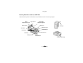
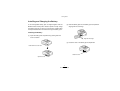
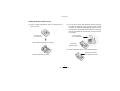
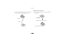
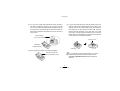
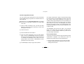
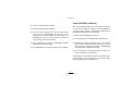
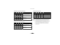
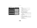
9(56$-(7 02%,/(35,17(5 036HULHV 8VHU¶V0DQXDO Proprietary Statement The information contained herein is proprietary and is provided sorely for the purpose of allowing customers to operate and maintain the equipment described herein. PC Worth Int’l Co., Ltd. reserves the right to make changes in specifications and other information contained in this document without prior notice. Liability Disclaimer PC Worth makes no warranty of any kind with regard to this publication, including, but not limited to, the implied warranty of merchantability and fitness for any particular purpose. PC Worth shall not be liable for technical or editorial errors or omissions contained herein; nor for incidental consequential damages in connection with the furnishing, performance, or use of this publication. This publication contains proprietary information that is protected by copyright. All rights are reserved. No part of this publication may be photocopied, reproduced or translated into any language, in any forms, in an electronic retrieval system or otherwise, without the prior written permission of PC Worth. No Liability for Consequential Damage In no event shall PC Worth or anyone else involved in the creation, production, or delivery of the accompanying product (including hardware and software) be liable for any damages whatsoever (including, without limitation, damages for loss of business profits, business interruption, loss of business information, or other pecuniary loss) arising out of the use of or the results of use of or inability to use such product, even if PC Worth has been advised of the possibility of such damages. Trademarks & Copyright All registered and unregistered trademarks used herein are the exclusive property of their respective owners. Copyright 1998-2005 PC Worth Int'l Co., Ltd. Copyright 1998-2005 Cino Group DOC NO : YMAUA4001000000 Agency Compliance and Regulatory Information This equipment has been tested and found to comply with the limits for a Class B digital device, pursuant to part 15 of the FCC rules. These limits are designed to provide reasonable protection against harmful interference in a residential installation. This equipment generates, uses and can radiate radio frequency energy and, if not installed and used in accordance with the instructions, may cause harmful interference to radio communications. However, there is no guarantee that interference will not occur in a particular installation. If this equipment does cause harmful interference to radio or television reception, which can be determined by turning the equipment off and on, the user is encouraged to try to correct the interference by one or more of the following measures: zReorient or relocate the receiving antenna. zIncrease the separation between the equipment and receiver. zConnect the equipment into an outlet on a circuit different from that to which the receiver is connected. zConsult the dealer or an experienced radio/TV technician for help. You are cautioned that changes or modifications not expressly approved by the party responsible for compliance could void your authority to operate the equipment. FCC RF Radiation Exposure Statement This equipment complies with FCC radiation exposure limits set forth for an uncontrolled environment. End users must follow the specific operating instructions for satisfying RF exposure compliance. This transmitter must not be co-located or operating in conjunction with any other antenna or transmitter The CE mark as shown above displayed on MP3200 series mobile printer indicates that this product has been tested in accordance with the procedures given in European Council R&TTE Directive (99/5/EC) and confirmed to comply with the European Standard EN 301 489-17, EN 300 328-2, EN 50371, EN 60950. פ܅ሽंᘿࡩሽᖲጥᙄऄ รԼԲය ᆖীڤᎁᢞٽհפ܅୴᙮ሽᖲΔॺᆖױΔֆΕᇆࢨࠌ݁ृشլᖐ۞᧢ޓ᙮ΕףՕפࢨ᧢ޓૠհࢤ֗פ౨Ζ รԼය פ܅୴᙮ሽᖲհࠌشլᐙଆڜ٤֗եឫٽऄຏॾΙᆖ࿇ڶեឫွழΔᚨܛمೖشΔࠀޏ۟ྤեឫழֱᤉᥛࠌشΖছႈٽऄຏॾΔ ਐࠉሽॾࡳ܂ᄐհྤᒵሽॾΖפ܅୴᙮ሽᖲႊٽ࠹ݴऄຏॾࢨՠᄐΕઝᖂ֗᠔᛭شሽंᘿ୴ࢤሽᖲໂհեឫΖ Table of Contents Getting Started................................ 1 Connecting MP3200 through RS232C...................... 17 Getting Familiar with Your MP3200............................ 2 Switch Functions.......................................................18 Installing and Charging the Battery ............................ 3 Indications.................................................................18 Installing the Battery ..................................................... 3 Intelligent Power Management .................................21 Charging the Battery ..................................................... 4 Using the Accessories .............................................. 22 Loading the Media Roll .............................................. 5 Maintenance and Troubleshooting........ 23 Loading Media Roll without Peeler ............................... 6 Loading Label Roll with Peeler ..................................... 7 Conduct Length Measurement...................................... 9 Verify MP3200 is Working ........................................ 10 Using Your MP3200 .......................... 11 Connecting MP3200 through IrDA ........................... 12 Decide IrDA Protocol and IrDA Port ............................ 12 Establish IrOBEX Connection ..................................... 13 Establish IrCOMM Connection.................................... 14 Connecting MP3200BT through Bluetooth............... 15 Cleaning Instructions ................................................ 24 Troubleshooting ........................................................25 Extending Battery Life...............................................25 Product Disposal....................................................... 26 Battery Disposal........................................................26 Getting Started Thank you for choosing VERSAJET MP3200 Series Mobile Printer. The MP3200 series mobile printer is designed with rugged yet lightweight architecture, delivering the ultimate convenience of mobility to meet your on-demand labels and receipts printing requirements. To meet various wireless communication requirements, the MP3200 series comes with two different models - MP3200 and MP3200BT. RS232C and IrDA communication interfaces are supported on both models. Moreover, the MP3200BT is compatible with most Bluetooth-enabled devices by incorporating Bluetooth 1.2 wireless technology. You can select the most suitable model to fulfill your demand. This user’s guide provides all of the information required for installation, operation, maintenance and troubleshooting. If you need more information, please contact your supplier or visit our web site for details. 1 Getting Started Getting Familiar with Your MP3200 Please familiarize yourself with the features of your MP3200 as shown in the following diagram. Media Compartment Cover Paper Sensor Platen Roller Media Width Adjustment Spacer RS232 Port Belt Clip DC Power Jack IrDA Port 2 POWER Button Feed Roller IrDA Port 1 Battery Cover LED Indicators PRESS Button Shoulder Strap Rings 2 MP3200 User’s Guide Getting Started Installing and Charging the Battery (2) Slide the battery pack into the battery pack compartment aligning with the arrow sign. A new rechargeable battery pack is shipped together with the MP3200 series mobile printer. Please unpack and fully charge the battery pack prior to using it for the first time. Please follow the steps indicated below to install and charge the battery pack : Installing the Battery (1) Open the battery pack compartment by pushing down the cover lock button. Align the Arrow Sign (3) Close the cover of the battery pack compartment. Push Down the Cover Lock Button Close the Cover Open the Cover 3 MP3200 User’s Guide Getting Started Charging the Battery Please refer to following table for detailed battery status. (1) Plug the power supply unit into the appropriate AC wall socket, then connect the DC plug of the power supply unit to MP3200(BT) DC power jack. a. Use of an unapproved power supply unit could damage the battery pack or MP3200(BT). b. For more information on the battery pack, please refer to “Extending Battery Life” and “Battery Disposal” for details. (2) Activate MP3200(BT) by pressing the POWER button. You will hear 3 short beeps in ascending tone to indicate power-on status. The LED indicators will flash 5 times to indicate current battery status. LED1 LED2 LED3 LED4 Battery Status Green Green Green Green More than 90% of battery remains Green Green Green Green Green More than 70% of battery remains More than 50% of battery remains Green More than 20% of battery remains Orange Less than 20% of battery remains Red Less than 10% of battery remains a. The MP3200(BT) gives 1 warning beep at 5 seconds intervals when the battery power is less than 20%. b. The MP3200(BT) gives 2 warning beeps at 5 seconds intervals when the battery power is less than 10%. (3) During battery status indication, the LED4 indicator will go on steady green after the LED indicators flash 3 times. This means MP3200(BT) is in charging state. You may check the battery status by pressing the POWER button during battery charging. While pressing the POWER button, the LED indicators will flash three times to indicate the battery status. (4) Following the battery status indication, the LED1 indicator of MP3200(BT) will flash green(red) at 2 seconds intervals. The MP3200(BT) is now ready to be connected. The MP3200(BT) battery pack has to be charged about 4~5 hours for the first time. You may check the battery status by pressing the POWER button. 4 MP3200 User’s Guide Getting Started Loading the Media Roll The MP3200(BT) is designed to print either receipt or label. Please decide the printing mode, media type and sensor type before loading the media roll. Sensor Type Printing Mode Both transmissive sensor and reflective sensor are available for page mode only : Transmissive Sensor This sensor is used to detect the different transmissive ratio between label and liner. The MP3200(BT) supports two printing modes : standard (line) mode and page mode. Reflective Sensor This sensor is used to detect the different reflective ratio between media and I-Mark (black mark). Standard (line) Mode - Default Setting In this mode, the MP3200(BT) prints data one line at a time. Page Mode In this mode, the MP3200(BT) prints data one page at a time. Media Type The following media types can be applied to MP3200(BT) : Continuous Receipt I-Mark Media (detected by reflective sensor) Gap Label (detected by transmissive sensor) 5 MP3200 User’s Guide Getting Started Loading Media Roll without Peeler (1) Open the media compartment cover by pushing down the cover lock knob. (2) You can find a media width adjustment spacer inserted in the media compartment groove. Push the spacer forward and pull it out. Adjust the width adjustment spacer to fit one of the grooves in accordance with the width of the media roll. Grooves are available for the width from 34 to 58 mm with 3 mm per pitch. Insert the Spacer in the Correct Direction Push Down the Cover Lock Knob Open the Media Compartment Cover (Upper) Media Width Adjustment Spacer (3) Set the media roll as shown in the following diagram. Make Sure the Direction of the Media Roll is Correct Media Compartment Cover (Front) 6 MP3200 User’s Guide Getting Started Loading Label Roll with Peeler (4) Pull out the media paper and thread it into the slot beneath the feed roller. Close the media compartment cover. (1) Open the media compartment cover by pushing down the cover lock knob. Push Down the Cover Lock Knob Feed Roller Open the Media Compartment Cover (Upper) Close the Cover Media Compartment Cover (Front) 7 MP3200 User’s Guide Getting Started (4) If you choose label printing by using the peeler function, the backing material will be peeled away from the label as it is printed. Tear the first label partially apart and thread the label edge into the slot beneath the feed roller, keep the backing material separated on the other side of the feed roller. Then, close the media compartment cover. Press the FEED button, the MP3200(BT) will forward the first label and remain ready in the next printing position. (2) You can find a media width adjustment spacer inserted in the media compartment groove. Push the spacer forward and pull it out. Adjust the width adjustment spacer to fit one of the grooves in accordance with the width of the label roll. Grooves are available for the width from 34 to 58 mm with 3 mm per pitch. Insert the Spacer in the Correct Direction Close the Cover Media Width Adjustment Spacer Feed Roller (3) Set the label roll as shown in the following diagram. Make Sure the Direction If you would like to use the peeler function, you have to conduct length measurement firstly. Please refer to “Conduct Length Measurement” before loading the label roll. of the Label Roll is Correct 8 MP3200 User’s Guide Getting Started Conduct Length Measurement You can conduct length measurement by using transmissive sensor (default setting) for gap label roll or reflective sensor for I-Mark media roll. If the length measurement is failed or executed without setting the correct media roll, the MP3200(BT) will issue a paper jam error. Please conduct length measurement once again. On condition that the length measurement is done successfully, the value will be stored into the flash memory. When you load the same media roll next time, the MP3200(BT) will perform top-of-form by feeding one label or one measured length of the receipt paper right after you close the media compartment cover in power-on state. Please refer to the Programming Reference for changing the sensor from transmissve to reflective, if the I-Mark media roll is used. (1) Open the media compartment cover, the LED1 and LED3 will light up orange and green respectively, and then start flashing after10 seconds. The MP3200(BT) will also feed one label or one measured length of the receipt paper while pressing the FEED button. However, if you load a different media roll, you will have to re-conduct length measurement. (2) Load the media roll. (3) Press the FEED button and release it. Revert to Standard Mode (4) Close the media compartment cover, the LED3 flashes green 3 times. The MP3200(BT) will feed four labels to execute length measurement. After the length measurement is completed, the MP3200(BT) will be ready in the next printing position and the LED1 of MP3200(BT) will flash green(red) at 2 seconds intervals. The printing mode will be switched to page mode after the length measurement is completed. If you would like to revert it to standard mode, please follow the steps indicated below : (1) Open the media compartment cover, the LED1 and LED3 will light up orange and green respectively, and then start flashing after10 seconds. (5) The MP3200(BT) is ready for page mode operation. 9 MP3200 User’s Guide Getting Started Verify MP3200 is Working (2) Load the receipt roll (without I-Mark). After fully charging the battery pack and loading the receipt roll, you can print a configuration message to verify MP3200(BT) is in proper working condition. A configuration message will be printed after executing the self-test procedure. (3) Press the FEED button and release it. (4) Close the media compartment cover, the LED3 flashes green 3 times. The MP3200(BT) will feed about 16 cm receipt paper and remain ready for the next printing. The MP3200(BT) will give two beeps, the LED1 and LED2 will light up orange and green respectively. (1) Make sure the MP3200(BT) is power off. (2) Press FEED button and POWER button simultaneously. (3) Release both POWER and FEED buttons. The LEDs will flash 5 times to indicate the battery status firstly, then the LED1 gives short orange blinks 10 times. The MP3200(BT) will start printing a configuration message. (5) Press “FEED” button, the LED1 of MP3200(BT) will flash green(red) at 2 seconds intervals. (6) The MP3200(BT) is now ready for standard mode operation. (4) Pull one edge of the receipt paper against the tear bar to tear the configuration message down. This message provides related information on firmware version, communications, power management, printer control setting, general specifications and head resistance. 10 MP3200 User’s Guide Using Your MP3200 The MP3200 series mobile printer has to establish communication with a host system which sends the data to be printed. There are three ways for connecting MP3200(BT) with the host system : By means of an IrDA wireless communication via IrOBEX or IrCOMM protocols. By means of a Bluetooth wireless communication via SPP protocol (MP3200BT only). By using a RS232C cable between printer and its host system. Please kindly note that the three communication interfaces can not be activated concurrently. If you select one of the communication interfaces, the other two will be disabled automatically. 11 Using Your MP3200 Connecting MP3200 through IrDA Decide IrDA Protocol and IrDA Port The MP3200(BT) is equipped with a standard IrDA interface. IrDA is an industry standard defined by the IrDA consortium (Infrared Data Association). It specifies a way to transfer data wirelessly via infrared radiation. The IrDA specifications include standards for both the physical devices and the protocols they use to communicate with each other. Before establishing an Infrared connection between MP3200(BT) and the host system, please decide the IrDA protocol and IrDA port in advance. The MP3200(BT) supports both IrOBEX and IrCOMM protocols. IrOBEX is enabled as the default setting. If you would like to use IrCOMM, you can use the printer command to change the default setting. Especially, the most popular IrOBEX and IrCOMM protocols are supported by the MP3200(BT). This allows MP3200(BT) to be compatible with most IrDA-enabled computing platforms, such as PC, laptop, PDA, PDT and mobile phone, etc. There are two IrDA ports available for communication. Port1 is on the upper side of the body, port2 is on the back side of the body. Both ports are enabled as the default setting. But sometimes the data might not be received correctly when transmission is in interruptive condition. If you wish to get a more reliable transmission, you are recommended to choose only the convenient one for your applications. You can use the printer command to change the default setting. IrOBEX stands for Infrared OBject EXchange and is an industry standard of the IrDA, which defines how “Objects” can be shared between different IrDA devices. The IrOBEX protocol has been built into the Microsoft Windows system and is supported by many various devices. Port 2 IrCOMM stands for Infrared COMMunications, which supports the legacy applications by emulating the RS232 serial port over the IrLMP/IrLAP protocol stack. Please note that the Microsoft Windows system does not support IrCOMM software driver, you have to obtain the IrCOMM driver from the third-party. Port 1 Please refer to the Programming Reference for changing the IrDA protocol and IrDA port. 12 MP3200 User’s Guide Using Your MP3200 Establish IrOBEX Connection (4) If the IrOBEX connection is built successfully, the LED2 will flash green and an IrOBEX connection icon will be displayed on the task bar with MP3200(BT)-0001 (0001 is the default setting of IrDA device ID). You can use the printer command to change the IrDA device ID. The following procedure of installation example describes how to connect MP3200(BT) with a host laptop in Windows 2000 using IrOBEX protocol for reference. Please note that the installation procedure may vary with each different host system and operating system. You have to follow the respective procedure to build the connection accordingly. IrOBEX Connection Icon (1) Make sure the battery pack is fully charged. You may refer to “Charging the Battery” for details. Please refer to the Programming Reference for changing the IrDA device ID. (2) Power on MP3200(BT) within the IrDA connection range. The LED indictors flash 5 times to indicate the battery status firstly. Following the battery status indication, the LED1 indicator of MP3200(BT) will flash green(red) at 2 seconds intervals. The MP3200(BT) is now ready to be connected. (5) The MP3200(BT) is now ready for print. a. Data may not be received correctly when transmission is under direct sun light, fluorescent lamps or strong lights. b. Data may not be received correctly if the MP3200(BT) has been left for an extended period in temperatures outside the recommended storage temperature range. (3) Direct the IrDA port of the host laptop towards the enabled IrDA port of MP3200(BT). Insure there is a direct line of sight and no obstacles between the host laptop and MP3200(BT) for properly sending and receiving signals. Communication o is available in the range of 15 up, down, left and right. c. Transmission distance varies according to the system used and the surrounding conditions. So it may not be possible to establish a connection within the connection range provided in the specifications. 13 MP3200 User’s Guide Using Your MP3200 Establish IrCOMM Connection (5) Please use the printer command to set the IrDA communication protocol as IrCOMM. The following procedure of installation example describes how to connect MP3200(BT) with a host laptop in Windows 2000 using IrCOMM protocol for reference. Please note that the installation procedure may vary with each different host system and operating system. You have to follow the respective procedure to build the connection accordingly. (1) (6) Direct the IrDA port of the host laptop towards the enabled IrDA port of MP3200(BT). Insure there is a direct line of sight and no obstacles between the host laptop and MP3200(BT) for properly sending and receiving signals. Communication o is available in the range of 15 up, down, left and right. Make sure the battery pack is fully charged. You may refer to “Charging the Battery” for details. (7) If the connection is built successfully, the LED3 will flash green and the IrCOMM icon will be changed as shown below. (2) Power on MP3200(BT) within the IrDA connection range. The LED indictors flash 5 times to indicate the battery status firstly. Following the battery status indication, the LED1 indicator of MP3200(BT) will flash green(red) at 2 seconds intervals. The MP3200(BT) is now ready to be connected. IrCOMM Icon Changed (8) The MP3200(BT) is now ready for print. (3) Install the IrCOMM driver supplied by the third-party. a. Data may not be received correctly when transmission is under direct sun light, fluorescent lamps or strong lights. (4) After completing the driver installation, an IrCOMM icon will be displayed on the task bar and a virtual COM port will be created automatically. b. Data may not be received correctly if the MP3200(BT) has been left for an extended period in temperatures outside the recommended storage temperature range. c. Transmission distance varies according to the system used and the surrounding conditions. So it may not be possible to establish a connection within the connection range provided in the specifications. 14 MP3200 User’s Guide Using Your MP3200 Connecting MP3200BT through Bluetooth Usually, the resident Bluetooth drivers will configure the SPP connection as one of the virtual COM ports in your host system that can be controlled and utilized by the user’s application programs. If your host system supports the functionality of PICONET, up to 7 units of MP3200BT can be connected to the same host system simultaneously. When a PICONET is formed, the host system acts as the master while the MP3200BTs act as slaves for the duration of the PICONET connection. The MP3200BT is equipped with a Bluetooth module which is compliant with the up-to-date Bluetooth£ 1.2 wireless technology. This enables wireless connectivity between MP3200BT and most Bluetooth-enabled devices, such as PC, laptop, PDA, PDT and mobile phone, etc. Usually, all actions between a program installed on your computer and a remote Bluetooth device are carried out by the Bluetooth services. A Bluetooth device can offer one or more services. These popular services include Serial Port (SPP), Dail-Up Networking (DUN), Human Interface Device (HID), Generic Object Exchange (GOEP), Personal Area Networking (PAN), Lan Access (LAP), Generic Access (GAP), and so on. The MP3200BT supports Serial Port service (SPP) which is one of the most popular Bluetooth services providing the serial radio link between Bluetooth master and slave devices. Under Bluetooth SPP, the remote Bluetooth system always acts as a master and MP3200BT always acts as a slave. The MP3200BT will only wait for the connection request issued by the remote Bluetooth master system to establish the radio link. Once the pre-built radio link is lost, the user has to re-build the radio link manually. 15 MP3200 User’s Guide Using Your MP3200 Establish Bluetooth Connection ® (3) Power on MP3200BT within the radio range. The LED indictors flash 5 times to indicate the battery status firstly. Following the battery status indication, the LED1 indicator of MP3200BT will flash red at 2 seconds intervals. The MP3200BT is now ready to be connected. Generally speaking, Widcomm provides complete Windows based Bluetooth software and its stacks have been broadly adopted by the Bluetooth industry. The following procedure of installation example describes how to connect MP3200BT with a host laptop in Windows 2000 using Widcomm Bluetooth driver for reference. The installation procedure may vary with each different remote Bluetooth host system, operating system and Bluetooth driver. You have to follow the respective procedure to build the connection accordingly. (4) Execute the Bluetooth Discovery procedure from the remote Bluetooth host laptop by following the steps indicated below : a. Right-click the Bluetooth icon at the taskbar, then select Explore My Bluetooth Places from the shortcut menu. (1) Make sure the battery pack is fully charged. You may refer to “Charging the Battery” for details. b. Double-click the Find Bluetooth Device. c. Check whether “MP3200BT-xxxx” is shown among the list of the discovered devices in the host laptop (xxxx is the last four numbers of the Bluetooth address). (2) Power on the remote Bluetooth host laptop and make sure the virtual COM port is available for connecting to MP3200BT. If the virtual COM port is not available, please follow the steps indicated below to add an additional COM port : (5) Establish the radio link between MP3200BT and the remote Bluetooth host laptop by following the steps indicated below : a. Select the Client Application tab from the Bluetooth configuration panel. a. Double-click MP3200BT-xxxx, you will find CINO SPP on MP3200BT-xxxx service in the Bluetooth host laptop. b. Click the Add COM Port button. c. Click OK. 16 MP3200 User’s Guide Using Your MP3200 Connecting MP3200 through RS232C b. Double-click “CINO SPP on MP3200BT-xxxx”, the PIN code or Passkey request balloon will appear over the notification area for security connection. Please enter “00000000”. The MP3200(BT) can communicate with a host system through a RS232C serial interface. The following procedure of installation example describes how to connect MP3200(BT) with a host laptop in Windows 2000 for reference. (6) You will hear 4 special beeps in ascending tone to indicate the radio link built. After that, the flashing LED1 will change the color from red to green. This means the MP3200BT is in radio-connected state. (1) Make sure the battery pack is fully charged. You may refer to “Charging the Battery” for details. (2) Plug the low-profile connector of RS232C cable into the serial port of MP3200(BT) with the arrow sign upward. The serial port is located on the right side of the body . (7) Your MP3200BT is now ready for print. If you would like to discontinue the radio link, you can either right-click the “MP3200BT-xxxx” to stop the CINO SPP service, or right-click the “CINO SPP on MP3200BT-xxxx” to stop the Bluetooth SPP service. You will hear 4 special beeps in descending tone when the radio link is disconnected. After that, the flashing LED1 will change the color from green to red. (3) Plug the other end of the RS232C cable into the serial port of the host laptop. (4) Power on MP3200(BT). The LED indicators flash 5 times to indicate the battery status. Following the battery status indication, the LED1 indicator of MP3200(BT) will flash green(red) at 2 seconds intervals. (5) The MP3200(BT) is now ready for print. 17 MP3200 User’s Guide Using Your MP3200 Switch Functions Indications The MP3200(BT) has two control buttons : POWER and FEED. The following tables show the status of MP3200(BT) by pressing each button in different states. The MP3200(BT) has two indicators, beeper and LED indicator. They will provide various indications according to the actual operating conditions and states. You may obtain necessary information to understand all details by referring to following descriptions. POWER Button State Operations Power Off zPress Power On zPress Beeping Indications to power on MP3200. No. and hold 2 seconds to power off MP3200. zPress to indicate the battery status. FEED Button State Power Off Operations zPress together with POWER button to run a self-test and print a configuration message. Normal Operation - Standard Mode zPress to feed around 20mm receipt paper. zPress to reprint the last print if a print stop caused by an error. - Page Mode zPress to feed one label. zPress to reprint the last print if a print stop caused by an error. Beeping Indications Descriptions 1 3 short beeps in ascending tone Power on indication 2 3 short beeps in descending tone Power off indication 3 1 beep at 5 seconds intervals Less than 20% of battery remains 4 2 beeps at 5 seconds intervals Less than 10% of battery remains 5 2 beeps Error warning 6 4 beeps in ascending tone Bluetooth radio link built 7 4 beeps in descending tone Bluetooth radio link lost 8 1 long beep Press POWER or FEED button 9 1 short beep Close the compartment cover 18 MP3200 User’s Guide Using Your MP3200 MP3200BT Communication Indications LED1 LED2 LED3 LED4 Red Blinking at 2 seconds intervals Battery Status Indications Status LED1 LED2 LED3 LED4 Battery Status MP3200BT is ready to be connected or is connected by RS232 interface. Green Green Green Green More than 90% of battery remains Green Green Green Green Green Green More than 70% of battery remains More than 50% of battery remains MP3200BT Bluetooth radio link built. Blinking at 2 seconds intervals Green More than 20% of battery remains Green Orange Less than 20% of battery remains Red Less than 10% of battery remains IrOBEX link built Blinking at 2 seconds intervals Green IrCOMM link built a. The MP3200(BT) gives 1 warning beep at 5 seconds intervals when the battery power is less than 20%. Blinking at 2 seconds intervals b. The MP3200(BT) gives 2 warning beeps at 5 seconds intervals when the battery power is less than 10%. MP3200 Communication Indications LED1 LED2 LED3 Green Blinking at 2 seconds intervals LED4 Status c. You may check the battery status by pressing the POWER button . MP3200 is ready to be connected or is connected by RS232 interface. Green IrOBEX link built Blinking at 2 seconds intervals Green IrCOMM link built Blinking at 2 seconds intervals 19 MP3200 User’s Guide Using Your MP3200 Error Indications LED1 LED2 Orange Green LED3 LED4 Start blinking after steady on for 10 seconds Orange (1) Paper jam : Open the media compartment cover and reload the media roll. Status Paper jam (*1) , or Label length measurement error (*2) (2) Label length measurement error : Check whether the sensor type and media type are correct. Green Media compartment cover opened (*3) Start blinking after steady on for 10 seconds Orange Green Green Green Re-conduct paper length measurement. Thermal head or motor overheated (*4) Start blinking after steady on for 10 seconds Red Green (3) Media compartment cover opened : Close the media compartment cover. Green Thermal head broken (*5) Start blinking after steady on for 10 seconds Red Green Green (4) Thermal head or motor overheated : The printer will automatically resume operation after the thermal head or motor cools down to the normal temperature. Green Thermal head or motor overcooled (*6) Start blinking after steady on for 10 seconds Red Green Green Command error (*7) Start blinking after steady on for 0.5 second (5) Thermal head broken : Call a qualified service technician to replace the thermal head. (*) Please refer to the following resolutions. (6) Thermal head or motor overcooled : The printer will automatically resume operation after the thermal head or motor comes to the normal temperature. (7) Command error : Reset MP3200(BT). Resend a correct command. 20 MP3200 User’s Guide Using Your MP3200 Intelligent Power Management The MP3200(BT) can be activated by one of the following actions : The power management of mobile printer is a critical essence to prolong battery life. This contributes to extend the duty cycle as long as possible to optimize the efficiency. The MP3200(BT) is powered by a high-capacity Li-Ion rechargeable battery pack. The advanced power management can make the entire operation intelligently for energy-saving to minimize the power consumption. Receive data through RS232C. Receive a printer command. Connected via IrDA or Bluetooth. Press POWER or FEED button. The unique power management scheme of the MP3200(BT) is accomplished by Power Saving, Auto Power Off and Auto Radio Off. Auto Power Off The MP3200(BT) will automatically power off in 5 minutes (default setting) after entering power saving state. You can use the printer command to set up the time frame from 00 to 255 minutes. If you set up the time frame to 00, the auto power off function will not be activated. When MP3200(BT) enters auto power off mode, you have to reactivate it by pressing the POWER button. Power Saving To conserve the power, the MP3200(BT) will enter power saving state by following two conditions indicated below : Press the POWER button to power on MP3200(BT), the LED indicators flash 5 times to indicate the battery status. Right after the battery status indication goes off, the MP3200(BT) will enter power saving state. Auto Radio Off For MP3200BT, the radio link will be disconnected after 20 minutes (default setting) of no operation in Bluetooth connected state. After that, the MP3200BT will enter power saving state. If there’s any error occurred, the MP3200(BT) will enter power saving state right after the steady LED warning indication turns into flashing. 21 MP3200 User’s Guide Using Your MP3200 Using the Accessories The MP3200(BT) is equipped with a belt clip and two shoulder strap rings for user’s convenience. Please refer to following figures for details. Belt Clip Hook the clip over your belt and ensure the clip is securely attached to the belt. Belt Clip Shoulder Strap Rings There are two shoulder strap rings on the top of MP3200(BT). You can snap each end of the shoulder strap into the rings. Shoulder Strap Rings 22 MP3200 User’s Guide Maintenance and Troubleshooting This Chapter provides some useful information for following topics: Cleaning Instructions Troubleshooting Extending Battery Life Product Disposal Battery Disposal 23 Maintenance and Troubleshooting Cleaning Instructions The MP3200(BT) should be cleaned after printing a few rolls of media or if there are voids in the printout. Thus, cleaning MP3200(BT) is a necessary maintenance activity to ensure optimum performance and life. Clean the Printer areas by using cleaning pen or cotton swabs moistened with isopropyl alcohol. Please refer to following procedure and figure to clean the Printer : Areas (1) Power off MP3200(BT). (2) Open the media compartment cover. (3) Remove the media roll. Methods Print Head Use the cleaning pen or a cotton swab moistened with isopropyl alcohol to clean the surface of the print head from end to end. Tear Bar Use the cleaning pen or a cotton swab moistened with isopropyl alcohol to clean the tear bar. Platen Roller Rotate the platen roller and clean the surface of the platen roller with cleaning pen or a cotton swab thoroughly. Interior Blow the paper dust by using a can of compressed air or by vacuuming. Ensure the paper sensor windows are free of dust. Exterior Use soft cloth moistened with water to clean the exterior of the printer. Paper Sensor Platen Roller Tear Bar Print Head a. Don’t use sharp objects to clean the print head. This may result in damage to the Printer. b. Let the print head cool to room temperature prior to cleaning, protecting yourself from burns. c. The tear bar has sharp edges. Please be careful when cleaning the tear bar to avoid possible injury. 24 MP3200 User’s Guide Maintenance and Troubleshooting Troubleshooting Extending Battery Life Please review following information to solve common problems you may encounter with MP3200(BT). If the problems are not covered in this section, please inquire to your supplier for technical support. Here are some tips for extending the overall life of your batteries : Problems No power Solutions zMake sure the battery pack is installed properly. zRecharge Media does not feed zEnsure Communication Error (3) Always use a Cino charger to charge. The use of any other kind of charger may damage the battery pack. the obstruction in paper path. zClean print head. zCheck and recharge the battery pack. zCheck the quality of media. zCheck if the media is loaded. zCheck baud rate. zReplace No print (2) Don’t disassemble, or modify a rechargeable battery pack. Otherwise, it will leak, overheat or crack. the battery pack. media cover is closed. zRemove Poor print quality (1) The battery storage temperature is 40°F to 104°F (4°C to 40°C). Don’t store a fully charged battery pack at temperature above this range for a long period – the battery pack may permanently lose charge capacity. (4) Remove the battery pack from MP3200(BT) if you will not use it for a long time. (5) Don’t touch or moisten the rechargeable battery pack with fresh water or seawater. If a battery pack is moistened, it will heat up or rust. cable to terminal. (6) Remember that any rechargeable battery pack will lose its ability to maintain a charge over time. It can only be recharged a finite number of times before it must be replaced. zMake sure the sensor and the media are set correctly. zVerify if the communication between the host system and the printer is established correctly. zReplace the battery pack. 25 MP3200 User’s Guide Maintenance and Troubleshooting Product Disposal Battery Disposal The MP3200(BT) complies with Directive 2002/69/EC of the European Parliament and of the Council of 27 January 2003 on Waste Electrical and Electronic Equipment (WEEE). Don’t dispose the used battery packs in unsorted waste. Please recycle them according to your local regulations. The Rechargeable Battery Recycling Corporation (RBRC) is a non-profit organization created to promote recycling of rechargeable batteries. For more information about how to recycle battery packs in your area, please visit www.rbrc.orgT This product has required the extraction and use of natural resources for its production. It may contain hazardous substances that could impact health and the environment, if not properly disposed. In order to avoid the dissemination of those substances in our environment and to diminish the pressure on the natural resources, we encourage you to use the appropriate take-back systems for product disposal. Those systems will reuse or recycle most of the materials of the product you are disposing in a sound way. The crossed out wheeled bin symbol informs you that the product should not be disposed of along with municipal waste and invites you to use the appropriate separate take-back systems for product disposal. If you need more information on the collection, reuse, and recycling systems, please contact your supplier for more information. 26 MP3200 User’s Guide ZZZFLQRFRPWZ