1
SERVICE MANUAL
Color Large Format Inkjet Printer
EPSON Stylus Pro 7600/9600
®
SEIJ01017
Notice:
All rights reserved. No part of this manual may be reproduced, stored in a retrieval system, or transmitted in any form or by any means, electronic,
mechanical, photocopying, recording, or otherwise, without the prior written permission of SEIKO EPSON CORPORATION.
The contents of this manual are subject to change without notice.
All effort have been made to ensure the accuracy of the contents of this manual. However, should any errors be detected, SEIKO EPSON would greatly
appreciate being informed of them.
The above not withstanding SEIKO EPSON CORPORATION can assume no responsibility for any errors in this manual or the consequences thereof.
EPSON is a registered trademark of SEIKO EPSON CORPORATION.
General Notice:
Other product names used herein are for identification purpose only and may be trademarks or registered trademarks of their
respective owners. EPSON disclaims any and all rights in those marks.
Copyright © 2002 SEIKO EPSON CORPORATION.
Imaging & Information Product Division
TPCS Quality Assurance Department
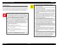
PRECAUTIONS
Precautionary notations throughout the text are categorized relative to 1)Personal injury and 2) damage to equipment.
DANGER
Signals a precaution which, if ignored, could result in serious or fatal personal injury. Great caution should be exercised in
performing procedures preceded by DANGER Headings.
WARNING
Signals a precaution which, if ignored, could result in damage to equipment.
The precautionary measures itemized below should always be observed when performing repair/maintenance procedures.
DANGER
1. ALWAYS DISCONNECT THE PRODUCT FROM THE POWER SOURCE AND PERIPHERAL DEVICES PERFORMING ANY MAINTENANCE
OR REPAIR PROCEDURES.
2. NO WORK SHOULD BE PERFORMED ON THE UNIT BY PERSONS UNFAMILIAR WITH BASIC SAFETY MEASURES AS DICTATED FOR
ALL ELECTRONICS TECHNICIANS IN THEIR LINE OF WORK.
3. WHEN PERFORMING TESTING AS DICTATED WITHIN THIS MANUAL, DO NOT CONNECT THE UNIT TO A POWER SOURCE UNTIL
INSTRUCTED TO DO SO. WHEN THE POWER SUPPLY CABLE MUST BE CONNECTED, USE EXTREME CAUTION IN WORKING ON
POWER SUPPLY AND OTHER ELECTRONIC COMPONENTS.
WARNING
1. REPAIRS ON EPSON PRODUCT SHOULD BE PERFORMED ONLY BY AN EPSON CERTIFIED REPAIR TECHNICIAN.
2. MAKE CERTAIN THAT THE SOURCE VOLTAGES IS THE SAME AS THE RATED VOLTAGE, LISTED ON THE SERIAL NUMBER/RATING
PLATE. IF THE EPSON PRODUCT HAS A PRIMARY AC RATING DIFFERENT FROM AVAILABLE POWER SOURCE, DO NOT CONNECT IT
TO THE POWER SOURCE.
3. ALWAYS VERIFY THAT THE EPSON PRODUCT HAS BEEN DISCONNECTED FROM THE POWER SOURCE BEFORE REMOVING OR
REPLACING PRINTED CIRCUIT BOARDS AND/OR INDIVIDUAL CHIPS.
4. IN ORDER TO PROTECT SENSITIVE MICROPROCESSORS AND CIRCUITRY, USE STATIC DISCHARGE EQUIPMENT, SUCH AS ANTISTATIC WRIST STRAPS, WHEN ACCESSING INTERNAL COMPONENTS.
5. REPLACE MALFUNCTIONING COMPONENTS ONLY WITH THOSE COMPONENTS BY THE MANUFACTURE; INTRODUCTION OF
SECOND-SOURCE ICs OR OTHER NON-APPROVED COMPONENTS MAY DAMAGE THE PRODUCT AND VOID ANY APPLICABLE EPSON
WARRANTY.
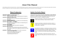
About This Manual
This manual describes basic functions, theory of electrical and mechanical operations, maintenance and repair procedures of the printer. The instructions and procedures included
herein are intended for the experienced repair technicians, and attention should be given to the precautions on the preceding page.
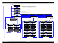
Manual Configuration
This manual consists of six chapters and Appendix.
CHAPTER 1.PRODUCT DESCRIPTIONS
Provides a general overview and specifications of the product.
CHAPTER 2.OPERATING PRINCIPLES
Describes the theory of electrical and mechanical operations of
the product.
CHAPTER 3.TROUBLESHOOTING
Describes the step-by-step procedures for the troubleshooting.
CHAPTER 4.DISASSEMBLY / ASSEMBLY
Describes the step-by-step procedures for disassembling and
assembling the product.
CHAPTER 5.ADJUSTMENT
Provides Epson-approved methods for adjustment.
CHAPTER 6.MAINTENANCE
Provides preventive maintenance procedures and the lists of
Epson-approved lubricants and adhesives required for servicing
the product.
APPENDIX Provides the following additional information for reference:
• Connector pin assignments
• Electric circuit boards components layout
• Electrical circuit boards schematics
• Exploded diagram & Parts List
Symbols Used in this Manual
Various symbols are used throughout this manual either to provide additional
information on a specific topic or to warn of possible danger present during a
procedure or an action. Be aware of all symbols when they are used, and
always read NOTE, CAUTION, or WARNING messages.
Indicates an operating or maintenance procedure, practice or
condition that is necessary to keep the product’s quality.
Indicates an operating or maintenance procedure, practice, or
condition that, if not strictly observed, could result in damage to,
or destruction of, equipment.
May indicate an operating or maintenance procedure, practice or
condition that is necessary to accomplish a task efficiently. It may
also provide additional information that is related to a specific
subject, or comment on the results achieved through a previous
action.
Indicates an operating or maintenance procedure, practice or
condition that, if not strictly observed, could result in injury or loss
of life.
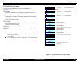
Revision Status
Revision
Date of Issue
A
May 10, 2002
Description
First release
EPSON Stylus Pro 7600/9600
Revision A
Contents
Chapter 1 Product Description
1.2.11.2 Accessories and Options for Stylus Pro 9600 .................................. 29
1.1 Product Description ............................................................................................ 12
1.1.1 Features ...................................................................................................... 12
1.1.2 Differences between Stylus Pro 7600 and Stylus Pro 9600 ...................... 13
1.2 Basic Specifications ............................................................................................
1.2.1 Print Specifications ....................................................................................
1.2.2 Character Specification ..............................................................................
1.2.3 Control Code ..............................................................................................
1.2.4 Paper Feed .................................................................................................
1.2.5 Paper Specifications ...................................................................................
1.2.5.1 Roll Paper ...........................................................................................
1.2.5.2 Sheet ...................................................................................................
1.2.5.3 Special Paper ......................................................................................
1.2.6 Mechanism Specifications .........................................................................
1.2.6.1 Printable Area .....................................................................................
1.2.6.2 Paper Set Lever ..................................................................................
1.2.6.3 Cutting Specification ..........................................................................
1.2.6.4 Acoustic Noise ...................................................................................
1.2.7 Electrical Specifications (TBD) .................................................................
1.2.8 Reliability ..................................................................................................
1.2.8.1 Total Print Volume .............................................................................
1.2.8.2 Print Head Life ...................................................................................
1.2.8.3 Maintenance Tank Life ......................................................................
1.2.8.4 Cutter Life average .............................................................................
1.2.8.5 Maintenance Parts (TBD) ...................................................................
1.2.9 Ambient Conditions ...................................................................................
1.2.9.1 Temperature/Humidity .......................................................................
1.2.9.2 Vibration .............................................................................................
1.2.9.3 Shock ..................................................................................................
1.2.9.4 Surrounding Space .............................................................................
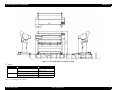
1.2.10 Overall Dimensions .................................................................................
1.2.11 Accessories ..............................................................................................
1.2.11.1 Accessories and Options for Stylus Pro 7600 ..................................
14
14
14
14
14
15
15
16
18
21
21
22
22
23
23
23
23
23
23
23
23
24
24
24
24
25
26
28
28
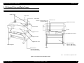
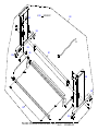
1.3 External View and Parts Names ......................................................................... 30
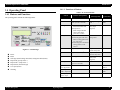
1.4 Operating Panel ..................................................................................................
1.4.1 Buttons and Functions ...............................................................................
1.4.1.1 Functions of Buttons ..........................................................................
1.4.1.2 LEDs ...................................................................................................
1.4.2 Indications on the Panel .............................................................................
1.4.2.1 lED Indications in Normal Mode .......................................................
1.4.2.2 LCD Indications in Normal Mode .....................................................
1.4.3 SelecType ..................................................................................................
1.4.3.1 Outline ................................................................................................
1.4.3.2 Panel Setting Menu Item ....................................................................
1.4.3.3 PG Setting ..........................................................................................
1.4.3.4 Page Lines ..........................................................................................
1.4.3.5 Interface Select ...................................................................................
1.4.3.6 Code Page Switching .........................................................................
1.4.3.7 Roll Paper Margin ..............................................................................
1.4.3.8 Detect Paper Width ............................................................................
1.4.3.9 Detect Skew Error ..............................................................................
1.4.3.10 Job Timeout Setting .........................................................................
1.4.3.11 No margin print setting ....................................................................
1.4.3.12 Cutter position adjustment ...............................................................
1.4.3.13 Auto margin refresh .........................................................................
1.4.3.14 Panel Setup Value Initialization .......................................................
1.4.3.15 Nozzle Check Pattern Printing .........................................................
1.4.3.16 Status Printing ..................................................................................
1.4.3.17 Job Information Print .......................................................................
1.4.3.18 Firmware version ..............................................................................
1.4.3.19 Printable pages of each ink cartridge ...............................................
1.4.3.20 Ink remaining ...................................................................................
1.4.3.21 Maintenance tank count ...................................................................
1.4.3.22 Use counter .......................................................................................
1.4.3.23 Clear use counter ..............................................................................
1.4.3.24 Job history display ............................................................................
31
31
31
32
33
33
34
35
35
36
40
41
41
41
41
42
42
42
43
44
44
45
45
46
48
49
49
49
49
50
50
50
6
EPSON Stylus Pro 7600/9600
1.4.3.25 Job history clear ................................................................................
1.4.3.26 Total prints .......................................................................................
1.4.3.27 Consumables life ..............................................................................
1.4.3.28 Suction adjustment for paper setting and indicator display .............
1.4.3.29 Ink remaining indicator display ........................................................
1.4.3.30 Job information .................................................................................
1.4.3.31 User Paper Setting ............................................................................
1.4.3.32 Power cleaning .................................................................................
1.4.3.33 Cutter Blade Replacement ................................................................
1.4.3.34 Gap Adjustment (Bi-D Adjustment, Uni-D Adjustment) ................
1.4.3.35 BK ink cartridge replacement ...........................................................
1.4.4 Maintenance Mode 1 .................................................................................
1.4.5 Maintenance Mode 2 .................................................................................
1.4.6 Paper feeding adjustment conversion table ...............................................
1.4.7 Firmware Reload .......................................................................................
1.4.7.1 Reload from ROM-DIMM .................................................................
1.4.7.2 Reload with F/W DOWNLOAD mode ..............................................
1.4.7.3 Installation with service utility (F/W Update function) .....................
1.4.7.4 Compulsory start F/W DOWNLOAD mode ......................................
1.4.8 Function to prevent irregular printing ........................................................
1.4.9 Initialization ...............................................................................................
1.4.9.1 Hardware initialization .......................................................................
1.4.9.2 Software initialization ........................................................................
1.4.9.3 Panel initialization ..............................................................................
1.4.10 Default Setup Values ...............................................................................
1.4.10.1 Initial Setting for Operation .............................................................
1.4.10.2 Ink Type Setting ...............................................................................
1.4.10.3 MW Printing Adjustment / Setting Values and Printing Modes ......
1.4.10.4 Printing Mode Combination Table ...................................................
Revision A
50
50
51
53
54
55
56
60
60
60
64
66
70
84
85
85
85
85
85
86
86
86
86
86
87
87
87
88
89
1.5 Controller ............................................................................................................ 90
1.6 Interfaces ............................................................................................................
1.6.1 Parallel Interface ........................................................................................
1.6.1.1 Compatibility Mode ...........................................................................
1.6.1.2 Nibble Mode .......................................................................................
1.6.1.3 ECP Mode ..........................................................................................
1.6.2 USB interface .............................................................................................
1.6.3 Optional Interface ......................................................................................
1.6.4 Supplements ...............................................................................................
91
91
91
93
94
95
96
97
1.7 Optional Units and Consumables ....................................................................... 98
1.7.1 Ink Cartridge ..............................................................................................
1.7.2 Cleaning cartridge ......................................................................................
1.7.3 Draining cartridge ......................................................................................
1.7.4 Maintenance Tank .....................................................................................
98
99
99
99
Chapter 2 Operating Principles
2.1 Overview .......................................................................................................... 101
2.2 Print Mechanism Components .........................................................................
2.2.1 Carriage (CR) Mechanism .......................................................................
2.2.2 Paper Feed Assembly ..............................................................................
2.2.3 Cleaning Mechanism ...............................................................................
2.2.4 Ink Supply Mechanism ............................................................................
2.2.5 Others .......................................................................................................
102
103
113
115
117
118
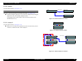
2.3 Outline of Control Circuit Board ...................................................................... 119
2.4 Outline of Power Supply Circuit Board ........................................................... 120
Chapter 3 Troubleshooting
3.1 Outline .............................................................................................................. 122
3.1.1 Introduction ............................................................................................. 122
3.2 Error Display ....................................................................................................
3.2.1 Errors .......................................................................................................
3.2.1.1 Error Indications on LCD .................................................................
3.2.1.2 Warning Indications on LCD ...........................................................
3.2.1.3 Service Call (Fatal) Errors ................................................................
3.2.2 Errors .......................................................................................................
3.2.2.1 Paper End/End of roll .......................................................................
3.2.2.2 Wrong paper source is selected on panel .........................................
3.2.2.3 Paper set lever is released during operation .....................................
3.2.2.4 Paper set lever is released .................................................................
3.2.2.5 Paper Jam .........................................................................................
3.2.2.6 Front Cover Open .............................................................................
3.2.2.7 Type-B I/F error ...............................................................................
3.2.2.8 Paper cutting error ............................................................................
3.2.2.9 Paper Not Straight ............................................................................
3.2.2.10 Paper check error/Paper eject error (sheet) ....................................
3.2.2.11 Paper is too thick for cleaning ........................................................
3.2.2.12 Not enough ink for cleaning ...........................................................
123
123
123
124
125
126
126
126
126
127
127
127
128
128
128
129
129
129
7
EPSON Stylus Pro 7600/9600
3.2.2.13 Ink-related Errors ........................................................................... 130
3.2.2.14 Defective ink cartridge ................................................................... 130
3.2.2.15 Ink lever released ............................................................................ 130
3.2.2.16 Illegal ink cartridge ........................................................................ 131
3.2.2.17 Maintenance tank full ..................................................................... 131
3.2.2.18 No Maintenance tank ...................................................................... 131
3.2.2.19 Wrong IK designation .................................................................... 131
3.2.2.20 Fatal Error ....................................................................................... 131
3.2.3 Troubleshooting for Warning .................................................................. 132
3.2.3.1 Ink Low ............................................................................................ 132
3.2.3.2 Maintenance tank full warning ......................................................... 132
3.2.3.3 Maintenance request ......................................................................... 132
3.2.4 Troubleshooting for Service Call Errors .................................................. 134
3.2.4.1 CR motor life (00000101) ................................................................ 134
3.2.4.2 PF motor encoder check error (00010000) ....................................... 135
3.2.4.3 PF Motor out of step (00010001) ..................................................... 135
3.2.4.4 PF motor overcurrent (00010002) .................................................... 136
3.2.4.5 PF motor in-position time out (00010003) ....................................... 136
3.2.4.6 CR motor encoder check error (00010004) ...................................... 137
3.2.4.7 CR motor out of step (00010005) ..................................................... 137
3.2.4.8 CR motor overcurrent (00010006) ................................................... 138
3.2.4.9 CR motor in-position time-out (00010007) ...................................... 138
3.2.4.10 Servo interrupt watchdog time-out (00010008) ............................. 139
3.2.4.11 System interrupt watchdog time-out (00010009) ........................... 139
3.2.4.12 CR home position sensor error (0001000A) .................................. 139
3.2.4.13 PF home position sensor error (0001000B) ................................... 139
3.2.4.14 Head slide (PG) home position sensor error (0001000C) .............. 140
3.2.4.15 CR motor PWM output faulty (0001000F) .................................... 140
3.2.4.16 PF motor PWM output faulty (00010010) ..................................... 141
3.2.4.17 Head driver (TG) temperature error (0001001B) ........................... 141
3.2.4.18 CR servo parameter error (0001001D) ........................................... 142
3.2.4.19 PF servo parameter error (0001001E) ............................................ 142
3.2.4.20 CSIC reed/right error (00010020) .................................................. 143
3.2.4.21 Ink type error (setting on printer body side) (00010022) ............... 143
3.2.4.22 RTC analysis error (00010023) ...................................................... 143
3.2.4.23 CSIC ROM communication error (00010025) ............................... 144
3.2.4.24 RTC communication error (00010026) .......................................... 144
3.2.4.25 Head error (00010028) ................................................................... 144
3.2.4.26 Unidentified NMI (00010029) ....................................................... 144
3.2.4.27 CR ASIC ECU error (0001002A) .................................................. 144
Revision A
3.2.4.28 PF ASIC ECU error (0001002B) ...................................................
3.2.4.29 NVRAM error (00020000) .............................................................
3.2.4.30 SDRAM error (00020002) .............................................................
3.2.4.31 BOOT program SUM error (00020003) ........................................
3.2.4.32 Flash memory SUM error (00020009) ...........................................
3.2.4.33 Program load error (0002000A) .....................................................
3.2.4.34 Internal memory shortage error (0002000B) .................................
3.2.4.35 Review error (0002000C) ...............................................................
3.2.4.36 CPU address error (load misalignment) (100000E0) .................
3.2.4.37 CPU address error (storage misalignment) (10000100) .................
3.2.4.38 CPU reserve command code exception error (10000180) .............
3.2.4.39 CPU slot illegal command exception error (100001A0) ................
3.2.4.40 CPU DMA address error (100005C0) ............................................
3.2.4.41 CPU error (10000xxx) ....................................................................
144
144
145
145
145
145
145
146
146
146
146
146
146
146
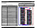
3.3 Troubleshooting Based on Your Printout .........................................................
3.3.1 Dot Missing .............................................................................................
3.3.2 Uneven Printing/Poor Resolution ............................................................
3.3.3 Smudged or Marred Printout (Front) .......................................................
3.3.4 Smudged or Marred Printout (Reverse side) ...........................................
3.3.5 White or Black Banding in the carriage running direction ......................
3.3.6 Banding in the paper feed direction .........................................................
147
147
148
148
149
149
150
Chapter 4 Disassembly & Assembly
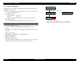
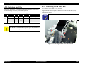
4.1 Summary ..........................................................................................................
4.1.1 Precautions ...............................................................................................
4.1.2 Tools ........................................................................................................
4.1.3 Screw List ................................................................................................
4.1.4 Disassembly Flow ....................................................................................
152
152
155
155
156
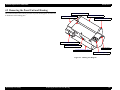
4.2 Removing the Panel Unit and Housing ............................................................
4.2.1 Panel Unit ................................................................................................
4.2.2 R Side Cover ............................................................................................
4.2.3 L Side Cover ............................................................................................
4.2.4 I/H Cover .................................................................................................
4.2.5 H Top Cover ............................................................................................
4.2.6 Rear Cover ...............................................................................................
4.2.7 Paper Guide L2 ........................................................................................
4.2.8 Roll Paper Cover .....................................................................................
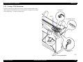
4.2.9 Front Cover ..............................................................................................
158
159
160
163
164
165
166
168
169
170
8
EPSON Stylus Pro 7600/9600
Revision A
4.3 Disassembly and Assembly of Carriage (CR) Mechanism ..............................
4.3.1 Print Head ................................................................................................
4.3.2 Damper ASSY .........................................................................................
4.3.3 CR Board ASSY ......................................................................................
4.3.4 Cutter Section ..........................................................................................
4.3.4.1 Cutter Holder ASSY .........................................................................
4.3.4.2 Cutter Solenoid .................................................................................
4.3.5 CR Encoder Sensor ASSY .......................................................................
4.3.6 P_EGDE Sensor ASSY ...........................................................................
4.3.7 CR Motor ASSY ......................................................................................
4.3.8 HEAD_SLIDE Sensor ASSY ..................................................................
4.3.9 CR_HP Sensor ASSY ..............................................................................
4.3.10 CR Encoder Scale (Timing Fence) ........................................................
171
171
173
174
175
175
177
178
179
180
182
183
184
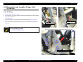
4.4 Disassembly and Assembly of Paper Feed Mechanism ...................................
4.4.1 PF Motor ..................................................................................................
4.4.2 PF Encoder Sensor ASSY .......................................................................
4.4.3 Cautions when replacing the PF Loop Scale ...........................................
4.4.3.1 Assembly Procedure for the PF Loop Scale ASSY .........................
4.4.3.2 PF Loop Scale ASSY Affixing Procedure .......................................
4.4.4 Suction Fans .............................................................................................
4.4.5 P_THICK Sensor/P_THICK Sensor_0.3 ASSY .....................................
4.4.6 P_REAR Sensor ASSY ...........................................................................
185
185
186
187
187
188
189
190
191
4.5 Disassembly and Assembly of Ink Supply Mechanism ...................................
4.5.1 C472_SUB-B Board ................................................................................
4.5.2 I/H (Ink Holder) ASSY ............................................................................
4.5.3 Cover Sensor ASSY ................................................................................
192
192
193
197
4.6 Disassembly and Assembly of Cleaning Mechanism ......................................
4.6.1 Maintenance ASSY Removal ..................................................................
4.6.2 Pump Motor ASSY ..................................................................................
4.6.3 Cap ASSY ................................................................................................
4.6.4 Pump ASSY .............................................................................................
4.6.5 Cleaner Head (Wiper) ..............................................................................
4.6.6 Flushing Box ASSY ................................................................................
198
199
200
200
201
203
204
4.7 Disassembly and Assembly of Circuit Boards .................................................
4.7.1 Power Supply Board ................................................................................
4.7.2 AC Inlet ...................................................................................................
4.7.3 MAIN Board (C472 MAIN) ....................................................................
4.7.4 DIP Switch and Jumper Setting at Factory before Shipment ..................
205
205
206
207
209
Chapter 5 Adjustment
5.1 Overview ..........................................................................................................
5.1.1 Cautions ...................................................................................................
5.1.2 Adjustment Tools ....................................................................................
5.1.3 Procedure for Adjustment Work ..............................................................
5.1.4 Adjustment Items .....................................................................................
5.1.4.1 Print Head Adjustment .....................................................................
5.1.4.2 Main Board Adjustment ...................................................................
5.1.4.3 CR Motor Adjustment ......................................................................
5.1.4.4 PF Motor Adjustment .......................................................................
5.1.4.5 P_EDGE Sensor ASSY Adjustment ................................................
5.1.4.6 P_REAR Sensor ASSY Adjustment ................................................
5.1.4.7 P_THICK/P_THICK_0.3 Sensor ASSY Adjustment .....................
5.1.4.8 CR Encoder Sensor ASSY Adjustment ...........................................
5.1.4.9 Cover Sensor ASSY Adjustment .....................................................
5.1.4.10 PF Encoder Sensor ASSY Adjustment ..........................................
5.1.4.11 Cutter Solenoid ASSY or Paper Guide L Adjustment ...................
5.1.4.12 Damper ASSY Adjustment ............................................................
5.1.4.13 Release Sensor (I/H Lever) Adjustment .........................................
5.1.4.14 Battery ............................................................................................
5.1.5 Parameter Backup ....................................................................................
5.1.5.1 Parameter Backup Procedure ...........................................................
5.1.5.2 Work Procedure ................................................................................
5.1.5.3 Others ...............................................................................................
5.1.6 Firmware Reinstallation ..........................................................................
5.1.6.1 Firmware Installation through ROM-DIMM ...................................
5.1.6.2 Firmware Installation through Interface ...........................................
211
211
211
212
212
212
213
214
214
215
215
215
215
216
216
217
217
217
217
218
218
218
218
219
219
219
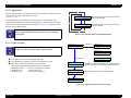
5.2 Self-diagnostic Function ...................................................................................
5.2.1 Overview .................................................................................................
5.2.1.1 How to Start Self-diagnostic Function .............................................
5.2.1.2 Functions of Keys during Self-diagnosis .........................................
5.2.1.3 Top Menu .........................................................................................
5.2.2 Test ..........................................................................................................
5.2.2.1 Version .............................................................................................
5.2.2.2 Control Panel ....................................................................................
5.2.2.3 Sensors .............................................................................................
5.2.2.4 Encoder .............................................................................................
5.2.2.5 Fan ....................................................................................................
5.2.2.6 Record ..............................................................................................
220
220
220
220
221
222
223
223
224
225
225
226
9
EPSON Stylus Pro 7600/9600
Revision A
5.2.2.7 CSIC ................................................................................................. 227
5.2.2.8 Actuator ............................................................................................ 229
5.2.2.9 Actuator 2 ......................................................................................... 229
5.2.3 Adjustment ............................................................................................... 230
5.2.3.1 Rear AD Adjustment ........................................................................ 231
5.2.3.2 Edge AD Adjustment ....................................................................... 232
5.2.3.3 Input Rank ........................................................................................ 233
5.2.3.4 Write D/A Value .............................................................................. 236
5.2.3.5 Check Nozzle ................................................................................... 237
5.2.3.6 Check Skew ...................................................................................... 238
5.2.3.7 Feed Correction + T&B Adjustment ................................................ 239
5.2.3.8 Top & Bottom Adjustment ............................................................... 242
5.2.3.9 Rear Sensor Position ........................................................................ 243
5.2.3.10 Platen Position (Sponge Position) Adjustment .............................. 244
5.2.3.11 Platen Position Checking ................................................................ 245
5.2.3.12 Head Slant Checking ...................................................................... 246
5.2.3.13 Round Trip Print Position Adjustment (Bi-D Adjustment) ............ 248
5.2.3.14 Parameter Copying ......................................................................... 251
5.2.3.15 Bi-D2 Adjustment (PG=0.7mm) .................................................... 251
5.2.3.16 Bi-D3 Adjustment (PG=2.1mm) .................................................... 251
5.2.3.17 Round Trip Print Position (Bi-D Adjustment) Checking ............... 252
5.2.3.18 Head Gap Adjustment (Uni-D Adjustment) ................................... 253
5.2.3.19 Test Pattern Printing ....................................................................... 255
5.2.3.20 Clean Head ..................................................................................... 256
5.2.3.21 Counter Clear ................................................................................. 257
5.2.4 Cleaning ................................................................................................... 259
5.2.5 Print .......................................................................................................... 259
5.2.6 Parameter ................................................................................................. 260
5.2.6.1 Parameter Initialize ........................................................................... 261
5.3 Mechanism Adjustment ....................................................................................
5.3.1 Overview ..................................................................................................
5.3.2 CR Timing Belt Tension Adjustment ......................................................
5.3.3 PF Timing Belt Tension Adjustment .......................................................
5.3.4 P_THICK_0.3/P_THICK Sensor Mounting Plate Position Adjustment .
5.3.5 Cover Sensor ASSY Mounting Position Adjustment ..............................
5.3.6 CR Encoder Sensor Mounting Position Adjustment ...............................
5.3.7 Cutter Positioning Adjustment ................................................................
5.3.7.1 Paper Cutting Position Check ...........................................................
5.3.8 PF Encoder Sensor Installation Position Adjustment ..............................
5.3.9 USB ID Writing .......................................................................................
Chapter 6 Maintenance
6.1 Overview .......................................................................................................... 275
6.1.1 Periodic Maintenance Items and Product Life Information .................... 276
6.1.2 Important Maintenance Items During Service Operations ...................... 279
6.2 Lubrication and Glue ........................................................................................ 280
6.2.1 Lubricating the CR Guide Rail ................................................................ 280
Chapter 7 Appendix
7.1 Connectors ........................................................................................................ 282
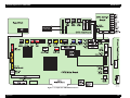
7.2 Component Layout ........................................................................................... 285
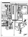
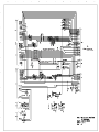
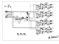
7.3 Circuit Diagrams .............................................................................................. 286
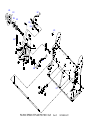
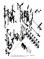
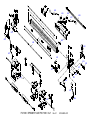
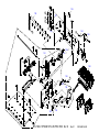
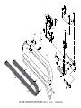
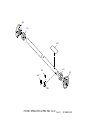
7.4 Exploded Diagrams .......................................................................................... 292
7.5 ASP List (Parts List) ......................................................................................... 317
7.5.1 ASP List for Stylus Pro 7600 .................................................................. 317
7.5.2 ASP List for Stylus Pro 9600 .................................................................. 320
263
263
263
264
265
267
268
269
271
272
273
10
1
CHAPTER
PRODUCT DESCRIPTION
EPSON Stylus Pro 7600/9600
Revision A
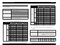
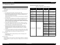
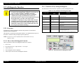
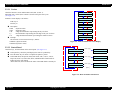
1.1 Product Description
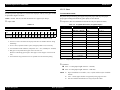
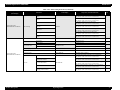
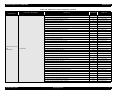
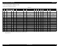
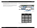
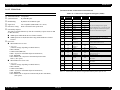
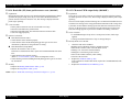
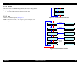
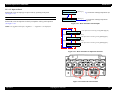
Stylus Pro 9600
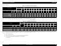
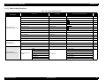
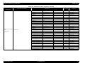
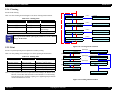
Table 1-2. Throughput (Stylus Pro 9600)
1.1.1 Features
Large Format
Stylus Pro 7600:
Stylus Pro 9600:
EPSON media
Pigment ink / Dye ink
Pigment ink:
•
•
•
Users can select following blackish ink combinations.
Photo Black + Light Black
Matte Black + Light Black
Matte Black × 2
Dye ink:
2 black ink cartridges are installed.
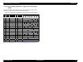
High-speed Throughput
Stylus Pro 7600
Quality
Resolution
(dpi)
Mode
Throughput
(A1 printing time)
Draft*1
360 × 180
Pseudo 4-color
2 min.
Speed
360 × 360
Bi-D MF 240 cps
3/2 (BK×2*2)
min.
Doubleweight
Matte Paper
Speed
360 × 360
Bi-D M/W(POL) 240 cps 5 min.
Quality
720 × 360
Bi-DFOL(POL)
9 min
Glossy Photo
Paper
Glossy PaperHeavy Weight
Speed
720 × 360
Bi-D 22POL 240 cps
8 min.
Quality
720 × 720
Bi-D 14POL 240 cps
13 min.
Adv.Photo
1440 × 720
Bi-D 4-pass 240 cps
25 min
Photo 2880
2880 × 1440
Bi-D 4-pass 190 cps
55 min
Plain Paper
Throughput
(A1 printing time)
Pseudo 4-color
3.5 min
Speed
360 × 360
Bi-D MF 240 cps
6/3.5 (BK×2*2)
min.
Doubleweight
Matte Paper
Speed
360 × 360
Bi-D M/W(POL) 240 cps 9 min.
Quality
720 × 360
Bi-DFOL(POL)
17 min
Glossy Photo
Paper
Glossy PaperHeavy Weight
Speed
720 × 360
Bi-D 22POL 240 cps
14 min
Quality
720 × 720
Bi-D 14POL 240 cps
24 min
Adv.Photo
1440 × 720
Bi-D 4-pass 240 cps
46 min
Photo 2880
2880 × 1440
Bi-D 4-pass 190 cps
102 min
Note *1:
Color high-speed 360×180dpi mode (for POP, for all ink combinations of pigment/
dye)
*2:
Black double-speed mode (for CAD, supported with FW),
(It is switched automatically with 2 BK ink cartridge installation (dye/PPI) + M/W
OFF)
Super High Quality
High image quality with 7-color ink, 2880×1440 dpi, and minimum 4pl various
layers.
Low Running Cost
• Independent for each color and 110 ml ink cartridge
• Large capacity 220 ml ink cartridge as an option
Paper Handling
•
•
•
•
Note *1:
Color high-speed 360×180dpi mode (for POP, for all ink combinations of pigment/
dye)
*2:
Black double-speed mode (for CAD, supported with FW),
(It is switched automatically with 2 BK ink cartridge installation (dye/PPI) + M/W
OFF)
Product Description
Mode
360 × 180
Table 1-1. Throughput (Stylus Pro 7600)
EPSON media
Resolution
(dpi)
Draft*1
Plain Paper
Max. 24 inch paper width, A1+ size supported
Max. 44 inch paper width, B0+ size supported
Quality
Support various media.
Automatic roll paper cutter, manual cutter
Automatic loading (cut sheet)
Borderless print for right and left
Compatibility with other LFPs
Commands are upper compatible with Stylus Pro 10000, Stylus Pro 10000CF,
Stylus Pro 9000, Stylus Pro 9500, Stylus Pro 7000, and Stylus Pro 7500.
The latest RIP technology
CPSI Pro software RIP
Product Description
12
EPSON Stylus Pro 7600/9600
Revision A
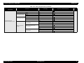
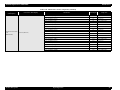
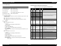
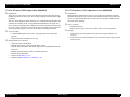
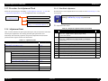
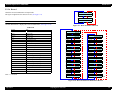
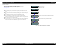
1.1.2 Differences between Stylus Pro 7600 and Stylus Pro
9600
Table 1-3. Differences between Stylus Pro 7600 and Stylus Pro 9600
Item
Product
Specifications
Maximum paper
width
RAM capacity
Option
Take-up Reel Unit
220 ml ink
cartridge
Product Description
Stylus Pro 7600
Stylus Pro 9600
610mm
(About 24 inches /
A1+size supported)
1118m
(About 44 inches /
B0+size supported)
32MB (16Mbit×2)
(IC600/601 = not mounted)
64MB (16Mbit×4)
Not supported
(CN30 = not mounted)
Supported
Not supported
Supported
Product Description
13
EPSON Stylus Pro 7600/9600
Revision A
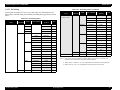
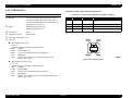
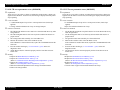
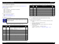
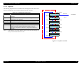
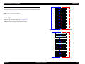
1.2 Basic Specifications
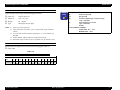
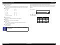
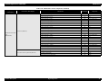
Table 1-5. Graphics Modes (Stylus Pro 9600)
1.2.1 Print Specifications
Printing:
Horizontal resolution
(dpi)
Printable area
Maximum number
of printable dots
Printing speed
360
1112 mm (43.78 inches)
15762
240 cps
On-demand ink-jet
Nozzle configuration:
Black:
192 nozzles (Black1, Black2, 96 nozzles each)
Color:
480 nozzles (cyan, magenta, light cyan, light magenta,
yellow, 96 nozzles each)
0.141mm (1/180 inch) for each color
Nozzle pitch:
31524
240 cps
1112 mm (43.78 inches)
63048
240 cps
2880
1112 mm (43.78 inches)
126087
190 cps
Character tables:
Bi-direction with logic seeking (high-speed return, high-speed skip only)
Printing speed and printable area
Character mode
Stylus Pro 7600:
Stylus Pro 9600:
• Printing speed:
Graphic Mode
1112 mm (43.78 inches)
1.2.2 Character Specification
Printing direction:
• Character quality:
• Character pitch:
• Printable area:
720
1440
2 international character sets
PC 437 (US, Standard Europe)
PC 850 (Multilingual)
NOTE: This specification is not described in the user's manual.
Typeface:
high quality
10 cpi
Bit map LQ font:
237 characters (at 10 cpi) / 8,561 dots (360dpi)
437 characters (at 10 cpi) / 15,840 dots (360dpi)
240 cps max.
EPSON Courier 10 cpi
NOTE: This specifications is not described in the user's manual.
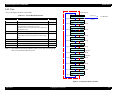
1.2.3 Control Code
Control code:
ESC/P Raster
ESC/P3
Table 1-4. Graphics Modes (Stylus Pro 7600)
Horizontal resolution
(dpi)
Printable area
Maximum number
of printable dots
Printing speed
360
604 mm (24.16 inches)
8698
240 cps
1.2.4 Paper Feed
Paper feeding:
Friction feed
Line spacing:
1/6 inch or programmable at 1440 inch
Paper path:
Roll paper/manual
Feed speed:
6.35 mm paper feed: 215 ± 10 msec
(except front rush, back rush, and hold time)
720
604 mm (24.16 inches)
17395
240 cps
1440
604 mm (24.16 inches)
34790
240 cps
2880
604 mm (24.16 inches)
69581
190 cps
Product Description
NOTE: This specifications is not described in the user's manual.
Basic Specifications
14
EPSON Stylus Pro 7600/9600
Revision A
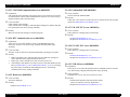
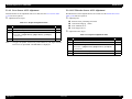
1.2.5 Paper Specifications
PLAIN PAPER
1.2.5.1 Roll Paper
Trouble-free paper feeding is ensured only in the following specifications.
Paper Size
ACCEPTABLE PAPER
Table 1-7. Acceptable Roll Paper Sizes (Plain Paper)
The printer accepts following plain paper and EPSON special paper. With any other
paper, proper paper feeding and satisfactory print quality are not ensured.
Paper Size
Table 1-6. Acceptable Roll Paper Sizes (Acceptable Paper)
Core
2-inch core
3-inch core
Core
2-inch core
Model
3-inch core
Paper Size
Stylus Pro 7600
203mm ~ 610 mm (W) × ~ 45 m (H) *
Stylus Pro 9600
203 mm ~ 1118 mm (W) × ~ 45 m (H) *
Stylus Pro 7600
203 mm ~ 610 mm (W) × ~ 202 m (H) *
Stylus Pro 9600
203 mm ~ 1118 mm (W) × ~ 202 m (H) *
Note "*": Within roll size
Roll Size
2-inch core: 103 mm ext. diameter maximum for 1 roll setting
3-inch core: 150 mm ext. diameter maximum for 1 roll setting
Model
Paper Size
Stylus Pro 7600
203 mm ~ 610 mm (W) × ~ 45m (H) *
Stylus Pro 9600
203 mm ~ 1118 mm (W) × ~ 45m (H) *
Stylus Pro 7600
203 mm ~ 610 mm (W) × ~ 202m (H) *
Stylus Pro 9600
203 mm ~ 1118 mm (W) × ~ 202m (H) *
Note "*": Within roll size
Roll Size
2-inch core: 103 mm ext. diameter maximum for 1 roll setting
3-inch core: 150 mm ext. diameter maximum for 1 roll setting
Thickness: 0.08 ~ 0.11 mm
Weight: 64 ~ 90gf/m2
Type: Plain paper, Recycle paper
Thickness: 0.08 mm ~ 0.50 mm
Product Description
Basic Specifications
15
EPSON Stylus Pro 7600/9600
Revision A
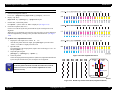
BORDERLESS PRINT ROLL PAPER
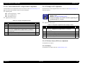
1.2.5.2 Sheet
Borderless print for right and left is enssured for roll paper with any of the paper widths
as specified in Figure 1-9 below.
ACCEPTABLE PAPER
NOTE: 300 mm, 400 mm, 500 mm and 600 mm are supported for Europe.
The printer accepts following plain paper and special paper. With any other paper,
proper paper feeding and satisfactory print quality are not ensured.
Paper Size (The sizes indicated in bold italic are only for Stylus Pro 9600.)
Paper width
Table 1-9. Acceptable Sheet Sizes (Acceptable Paper)
Table 1-8.
Paper Size
Stylus Pro 7600
Stylus Pro 9600
Japan
8”
USA/Europe
8”
210
mm
210
mm
10”
-
12”
14”
-
16”
-
20”
-
24”
36”
44”
10”
300
mm
12”
14”
400
mm
16”
500
mm
20”
600
mm
24”
36”
44”
Note 1: Paper should have no wrinkles, tears, or folds and the surface should be smooth.
2: The force to remove the end of the roll paper from the core should be between 300 gf
and 2000 gf
3: If core is used, a product-exclusive option (roll paper spindle 3 inch) is necessary.
4: It is used under normal conditions. (temperature 15°C ~ 25°C, humidity 40 ~ 60%RH)
5: Roll paper can be printed before paper comes out of the core.
(Reference: Remaining paper length is 30cm approx. when roll paper come out of the
core.)
6: The mechanism clips print data out of over-printable area for borderless printing.
Size (W × H)
Paper Size
Size (W × H)
B0+*
1118 mm × 1580 mm
A4
210 mm × 297 mm
B0 *
1030 mm × 1456 mm
US E
34 × 44 in
B1 *
728 mm × 1030 mm
US D
22 × 34 in
B2
515 mm × 728 mm
US C
17 × 22 in
B3
364 mm × 515 mm
US B
11 × 17 in
B4
257 mm × 364 mm
44 × 36 in *
44 × 36 in
A0+ *
914 mm × 1292 mm
30 × 24 in
30 × 24 in
A0 *
841 mm × 1189 mm
Letter
8.5 × 11 in
A1+
24 × 36 in
B1 (wide) *
1030 × 728 mm
A1
594m × 841 mm
8 × 10 in
8 × 10 in
A2
420 mm × 594 mm
30 cm × 45 cm
30 cm × 45 cm
A3+
329 mm × 483 mm
60 cm × 90 cm
60 cm × 90 cm
A3
297 mm × 420 mm
Note "*": Only for Stylus Pro 9600
Thickness
0.08 ~ 1.5 mm (paper length: 279 mm ~ 728 mm)
0.08 ~ 0.5 mm (paper length: 728 mm ~ 1580 mm)
NOTE 1: Paper should have no wrinkles, tears, or folds and the surface should be
smooth.
2: 0.08 ~ 1.50 mm paper thickness is supported for long-edge insertion.
3: The sizes indicated in bold italic are only for Stylus Pro 9600.
Product Description
Basic Specifications
16
EPSON Stylus Pro 7600/9600
Revision A
PLAIN PAPER
C H E C K
P O IN T
Proper feeding is ensured only in the following specifications.
Paper Size:
Same as above list
Thickness:
0.08 ~ 0.11 mm
Weight:
64 ~ 90 gf/m2
Type:
Plain paper, Recycle paper
NOTE 1: Paper is fed short-edge first.
2: Paper should have no wrinkles, tears, or folds and the surface should be
smooth.
3: It is used under normal conditions (temperature 15 ~ 25°C, humidity 40 ~
60%RH)
4: 300mm, 400mm, 500mm, 600mm are supported for Europe.
5: Mechanism clips print data out of over-printable area for borderless print.
Description of units of measure
cpi:
characters per inch
dpi:
dots per inch
cps:
characters printed per second (at 10 cpi)
1 cps = 2.54 mm/s
ips:
travel in inches per second
1 ips = 25.4 mm/s
G:
Gravity
General ambient conditions:
Temperature 15°C ~ 25°C
Humidity 40% ~ 60%
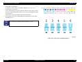
BORDERLESS PRINT WIDTH
Borderless print for right and left is assured with following paper width. *4
Paper width
Table 1-10.
Stylus Pro 7600
Stylus Pro 9600
Japan
8”
USA/Europe
8”
210
mm
210
mm
Product Description
10”
-
12”
14”
-
16”
-
20”
-
24”
36”
44”
10”
300
mm
12”
14”
400
mm
16”
500
mm
20”
600
mm
24”
36”
44”
Basic Specifications
17
EPSON Stylus Pro 7600/9600
Revision A
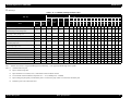
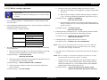
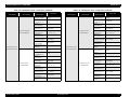
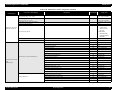
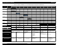
1.2.5.3 Special Paper
Roll (pigment)
Table 1-11. Availability with Special Paper (Pigment)
Characteristic
Roll / Pigment
Name
Black INK
Media Size
Paper
core”
Auto Borde
thickness
spindle
cut rless
(mm)
USA/
MK MK PK
Japan Europe
×2 +LK +LK
/Asia
10”
30
cm
12”
14”
40
cm
16”
50
cm
20”
22”
60
cm
24”
36”
203
210
254
300
305
356
400
406
500
508
560
600
610
914 1118
44”
{
{
{
2
0.21
~
-
-
-
-
-
-
-
-
-
-
-
-
~
~
~
Glossy Paper - Photo Weight
{
{
{
2
0.22
~
-
-
-
-
-
-
-
-
-
-
~
-
-
~
~
Glossy Film
{
{
{
2
0.13
~
-
-
-
-
-
-
-
-
-
-
-
-
~
~
~
Premium Glossy Photo Paper
{
{
{
2
0.18
~
-
-
-
-
-
-
-
-
-
-
-
-
~
~
~
Premium Semigloss Photo Paper
{
{
{
2
0.18
~
-
-
-
-
-
-
-
-
-
-
-
-
~
~
~
Photo Glossy Paper / Photo Grade Glossy Paper
{
{
{
2
0.17
~
-
-
-
-
-
-
-
-
-
-
-
-
~
~
~
Photo Semigloss Paper / Photo Grade Semigloss Paper
{
{
{
2
0.18
~
-
-
-
-
-
-
-
-
-
-
-
-
~
~
~
Premium Glossy Photo Paper (250)
{
{
{
3
0.26
~
~
-
-
-
-
-
-
-
-
-
-
-
-
~
~
~
Premium Semigloss Photo Paper (250)
{
{
{
3
0.26
~
~
-
-
-
-
-
-
-
-
-
-
-
-
~
~
~
Premium Semimatte Photo Paper (250)
{
{
{
3
0.26
~
~
-
-
-
-
-
-
-
-
-
-
-
-
~
~
~
Premium Luster Photo Paper
{
{
{
3
0.26
~
~
~
Watercolor Paper - Radiant White
{
{
{
{
3H
0.29
~
{
{
{
3H
{
{
{
{
{
Textured Fine Art Paper (Roll)
{
Canvas
Backlight Film
z
210
mm
Doubleweight Matte Paper
Smooth Fine Art Paper (Roll)
z
8”
-
-
~
~
~
~
~
~
~
-
~
~
~
-
-
-
-
-
-
-
-
-
-
-
-
~
~
~
0.37
-
-
-
-
-
-
-
-
-
-
-
-
~
~
~
3H
0.37
-
-
-
-
-
-
-
-
-
-
-
-
~
~
~
{
2
0.46
~
{
2
0.13
{
2
z
{
{
{
Backlight Film (USA / Europe)
-
-
-
-
-
-
-
-
-
-
-
-
~
~
-
-
-
-
-
-
-
-
-
-
-
-
~
~
~
0.18
-
-
-
-
-
-
-
-
-
-
-
-
~
~
~
2
0.28
-
-
-
-
-
-
-
-
-
-
-
-
~
~
~
~
~
{
{
Enhanced Synthetic Paper
{
{
z
z
{
2H
0.12
~
-
-
-
-
-
-
-
-
-
-
-
-
~
~
Adhesive Enhanced Synthetic Paper
{
{
z
z
{
2H
0.17
~
-
-
-
-
-
-
-
-
-
-
-
-
~
~
~
Tyvek Brillion
{
z
z
{
2
0.24
~
-
-
-
-
-
-
-
-
-
-
-
-
~
~
~
Adhesive Vinyl
{
z
z
{
2
0.33
-
-
-
-
-
-
-
-
-
-
-
-
~
~
~
{
~
Heavyweight Polyester Banner
{
{
{
3
0.25
~
-
-
-
-
-
-
-
-
-
-
-
-
~
~
TBD
TBD
{
2
TBD
~
-
-
-
-
-
-
-
-
-
-
-
-
~
~
-
Semiglossy 4
{
{
2
TBD
~
-
-
-
-
-
-
-
-
-
-
-
-
~
~
-
Dupont / EPSON Semi - Gloss Proofing Paper - A
{
{
2
0.20
-
-
-
-
-
-
-
-
-
-
-
-
~
~
-
Enhanced Matte Paper
Semiglossy 2
Note : Symbol ~: Assured, {: Supported, z: Supported conditionally, ×: Not supported, 2H/3H: High tension spindle
Product Description
Basic Specifications
18
EPSON Stylus Pro 7600/9600
Revision A
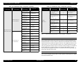
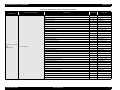
Roll (dye)
Table 1-12. Availability with Special Paper (Dye)
Characteristic
Roll / Dye
Name
Japan
USA/
Europe/
Asia
core”
spindle
Media Size
8”
Paper
thickness Auto cut Borderless
(mm)
203
210
mm
10” 30cm 12”
14” 40cm 16” 50cm 20”
22” 60cm 24”
36”
210
254
300
305
356
400
406
500
508
560
600
610
914 1118
44”
Presentation Matte Paper
{
{
2
0.20
{
-
-
-
-
-
-
-
-
-
-
-
-
~
~
~
Semigloss Photo Paper (Asia / Europe)
Semi Gloss Paper - Heavy Weight (US)
{
{
2
0.21
{
-
-
-
-
-
-
-
-
-
-
-
-
~
~
~
Glossy Photo Paper (Asia / Europe)
Glossy Paper - Heavy Weight (US)
{
{
2
0.23
{
-
-
-
-
-
-
-
-
-
-
-
-
~
~
~
{
2
0.21
{
-
-
-
-
-
-
-
-
-
-
-
-
~
~
~
{
{
2
0.13
{
-
-
-
-
-
-
-
-
-
-
-
-
~
~
~
Photo Grade Glossy Paper (Asia / Europe)
Photo Glossy Paper (US)
{
2
0.17
{
-
-
-
-
-
-
-
-
-
-
-
-
~
~
~
Photo Grade Semigloss Paper (Asia / Europe)
Photo Semigloss Paper (US)
{
2
0.18
{
-
-
-
-
-
-
-
-
-
-
-
-
~
~
~
-
-
-
-
-
-
-
-
-
-
-
-
~
~
~
-
-
-
-
-
-
-
-
-
-
-
~
~
~
-
-
-
-
-
-
-
-
-
-
-
-
~
~
~
-
-
~
~
~
~
~
~
~
~
-
~
~
~
~
Doubleweight Matte Paper
Glossy Film
Heavyweight Polyester Banner
{
{
2
0.28
RC 10mil Glossy Paper (TBD)
TBD
{
3
0.26
{
RC 10mil Semigloss Paper (TBD)
TBD
{
3
0.26
{
Premium Luster Photo Paper
TBD
{
3
0.26
{
~
Dupont / EPSON Commercial Proofing Paper
{
2
0.21
{
-
-
-
-
-
-
-
-
-
-
-
-
~
~
-
Dupont / EPSON Commercial Matte Proofing Paper
{
2
0.24
{
-
-
-
-
-
-
-
-
-
-
-
-
~
~
-
Dupont / EPSON Publication Proofing Paper
{
2
0.24
{
-
-
-
-
-
-
-
-
-
-
-
-
~
~
-
Note : Symbol ~: Assured, {: Supported, z: Supported conditionally, ×: Not supported, 2H/3H: High tension spindle
Note *1:
Assured with Uni-D print.
*2:
Paper is fed short-edge first.
*3:
Paper should have no wrinkles, tears, or folds and the surface should be smooth.
*4:
It is used under normal conditions (temperature 15°C ~ 25°C, humidity 40% ~ 60%RH)
*5:
Paper feeding and print quality with borderless print is not assured on paper which is not assured for borderless print.
*6:
Borderless print is not assured with sheet.
Product Description
Basic Specifications
19
EPSON Stylus Pro 7600/9600
Revision A
Sheet (pigment)
Table 1-13. Availability with Sheets (Pigment)
Characteristic
Sheet / Pigment
Black INK
Media size
Super
A4
LTR
A3
B
A2
C
B2
A1
D
24”×30” 30”×40” 36”×44”
A3/B
Paper
thickness
(mm) 210×297 216×279 297×420 279×432 329×483 420×594 432×559 515×728 728×1030 559×864 610×762 762×1016 914×1118
Japan
USA/
Europe/
Asia
Glossy Paper - Photo Weight
{
{
Watercolor Paper - Radiant White
{
{
{
{
{
{
{
0.67
Name
Smooth Fine Art Paper
Textured Fine Art Paper
Enhanced Matte - Poster Board
MK MK PK
×2 +LK +LK
{
TBD
{
{
{
0.67
{
{
{
{
1.3
~
~
~
~
~
-
-
-
-
-
-
-
-
-
~
-
-
-
-
-
-
-
-
-
-
-
-
-
-
-
-
-
-
-
-
-
-
-
-
-
-
-
-
-
-
-
-
-
-
-
~
-
~
-
-
~
-
~
-
-
~
~
-
Note : Symbol ~: Assured, {: Supported, z: Supported conditionally, ×: Not supported, 2H/3H: High tension spindle
Sheet (dye)
Table 1-14. Availability with Sheets (Dye)
Characteri stic
Mediasize
Sheet / Dye
Paper
thickness
A4
LTR
A3
B
Super
A3/B
210×297
216×279
297×420
279×432
329×483
420×594
432×559
515×728
728×1030
559×864
728×1030
~
~
~
~
~
-
-
-
-
-
-
A2
C
B2
A1
D
B1”
Japan
USA/Europe
/Asia
Glossy Photo paper
{
{
Photo Quality Inkjet Paper
{
{
~
~
~
~
~
~
~
-
-
-
Glossy Film
{
{
~
~
~
~
~
-
-
-
-
-
{
-
-
-
-
-
-
-
~
-
-
Name
Semigloss Paper - Poster Board
~
Note : Symbol ~: Assured, {: Supported, z: Supported conditionally, ×: Not supported, 2H/3H: High tension spindle
Note *1:
*2:
Assured with Uni-D print.
Paper is fed short-edge first.
*3:
Paper should have no wrinkles, tears, or folds and the surface should be smooth.
*4:
It is used under normal conditions (temperature 15°C~25°C, humidity
40%~60%RH)
Product Description
Basic Specifications
20
EPSON Stylus Pro 7600/9600
Revision A
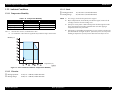
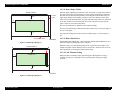
For borderless print, right and left margins are 3mm each because skew detection
1.2.6 Mechanism Specifications
limit is 3mm. If the distance from the paper edge to the platen (sponge width) is
less than 3mm, the maximum surplus print quantity without ink discharge onto the
platen (0mm~3mm) is printable area.
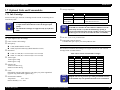
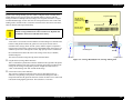
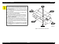
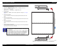
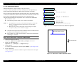
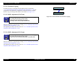
1.2.6.1 Printable Area
Table 1-15. Printable Area
PW
(Paper width)
Roll paper
/Sheet
Roll paper
Sheet
PL
(Paper length)
TM
(Top margin)
RM
(Right margin)
Dimension
Stylus Pro 7600
203 mm ~ 610 mm
Stylus Pro 9600
203 mm ~ 1118 mm
Stylus Pro 7600
203 mm ~ 610 mm
Stylus Pro 9600
203 mm ~ 1118 mm
Roll paper
Stylus Pro 7600/Stylus Pro 9600
Max. 202m
Sheet
Stylus Pro 7600/Stylus Pro 9600
279 mm ~ 1580 mm
Roll paper
Stylus Pro 7600/Stylus Pro 9600
3 mm/15 mm
Sheet
Stylus Pro 7600/Stylus Pro 9600
3 mm
Stylus Pro 7600/Stylus Pro 9600
3 mm/15 mm
Stylus Pro 7600/Stylus Pro 9600
14 mm
Roll paper
Stylus Pro 7600/Stylus Pro 9600
0 mm/3 mm/15 mm
Sheet
Stylus Pro 7600/Stylus Pro 9600
0 mm/3 mm
Roll paper
Stylus Pro 7600/Stylus Pro 9600
0 mm/3 mm/15 mm
Sheet
Stylus Pro 7600/Stylus Pro 9600
0 mm/3 mm
BM
Roll paper
(Bottom margin) Sheet
LM
(Left margin)
Model
Paper Feed Direction
Item
Printable Area
The printer detects paper width when paper is set. (If paper width detection setting
is OFF, it does not detect paper width.)
It does not print the image beyond the detected paper width or the printable area
specified by paper size setting.
(It may print on the platen if paper width detection setting is OFF.)
Margins of roll paper can be changed on the panel as follows;
Top/bottom 15 mm, left/right 3 mm
Top/bottom/left/right 3 mm
Top/bottom/left/right 15 mm
Figure 1-1. Printable Area
NOTE: Under special conditions, it is possible to set right and left margin (LM,
RM) to 0.
Product Description
Basic Specifications
21
EPSON Stylus Pro 7600/9600
Revision A
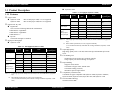
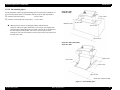
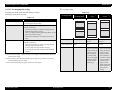
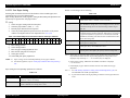
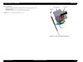
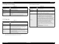
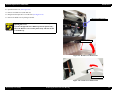
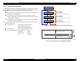
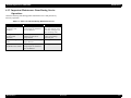
1.2.6.2 Paper Set Lever
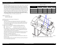
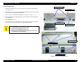
Table 1-17. Cutting Conditions and Cutting Methods
Cut condition
Table 1-16. Paper Set Lever
Lever Position
Initial cut (Cut with pushing “Cut/Eject” button after paper Paper is fed for L1 length and cut in 4 steps.
is set, and set lever is pushed down.)
(50cps)
Description
In the rear
Position for paper setting
(You can set paper.)
In the front
Ready-to-print position
(Paper is held with the paper holder.)
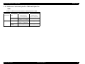
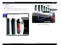
1.2.6.3 Cutting Specification
Cut after print completed by driver
4-step cut (200cps) When paper is shorter
than L2, it is cut after feeding L2.
Initial cut during printing
Cut during printing is not allowed with this
printer. (Product specification)
Initial cut during normal waiting status
Paper is fed for L1 length and cut in 4 steps.
(50cps)
4-step cut (200cps), when paper is longer
Initial cut with Auto cut ON after print with Auto cut OFF. than L2. 4-step cut (50cps) after feeding L2,
when paper is shorter than L2.
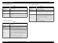
There are two methods to cut roll paper, automatic and manual cutting.
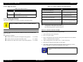
C A U T IO N
Cut method
Do not use the auto cutting function with any paper for which auto
cutting is prohibited; otherwise, the head would be damaged.
Cut with Paper width detection OFF
3-step cut always (100cps fixed)
Note : Cutting pressure at high speed can be changed.
Cutting pressure at low speed is “Duty: 45%” fixed.
Paper edge waiting position is fed L2 for initial cut.
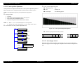
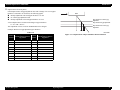
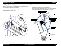
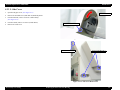
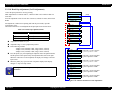
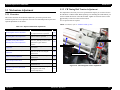
AUTOMATIC CUTTING OF ROLL MEDIA
MANUAL CUTTING OF ROLL PAPER
Automatic cutting under the following conditions can only be performed on the
approved media.
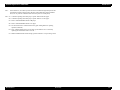
Manual cutting is performed by the following procedure.
1.
Select “Roll Cutter Off” on the panel.
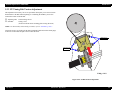
Mechanical conditions
Distance between cut position and paper setting position:
Distance between cut position and cutter mark:
Minimum cut length (same as paper edge waiting position):
2.
Press “Cut/ Eject” button.
3.
Paper is automatically fed toward the cutter guide, and printer becomes Off-line.
“Pause” is indicated on the LCD panel.
4.
Adjust cutting position with “Paper Feed +/-” button if necessary.
5.
Slide the cutter along the cutter guide to cut the paper.
6.
After cutting, release the printer from the pause status by pressing the “Pause”
button. Then paper is fed backward and printer enters on-line.
L0=167mm
L1= 44mm
L2=030mm
C H E C K
P O IN T
Product Description
Basic Specifications
For manual cutting of roll paper, use the manual cutter available as
an option.
22
EPSON Stylus Pro 7600/9600
Revision A
1.2.8 Reliability
1.2.6.4 Acoustic Noise
Level:
Approx. 50dB(A) (According to ISO 7779)
1.2.8.1 Total Print Volume
Stylus Pro 7600: 50,000 pages, 6.5million pass approx. (A1, 360×360 M/F, Bi-D)
1.2.7 Electrical Specifications (TBD)
Stylus Pro 9600: 20,000 pages, 5million pass approx. (B0, 360×360 M/F, Bi-D)
Rated voltage:
AC 100 ~ 240V
1.2.8.2 Print Head Life
Input voltage range:
AC 90 ~ 264V
Monochrome: 28billion shot / nozzle
Rated frequency range:
50 ~ 60Hz
Color: 28billion shot / nozzle
Input frequency range:
49 ~ 61Hz
Rated current:
Stylus Pro 7600:
Stylus Pro 9600:
1.0A/100-120v, 0.5A/220-240v
1.0A/100-120v, 0.5A/220-240v
Power consumption:
Operation status:
Waiting status:
Power OFF:
Stylus Pro 7600: 11,000 pages approx.
(A1, plain paper, Speed mode, continuous print)
Stylus Pro 9600: 5,000 pages approx.
(B0, plain paper, Speed mode, continuous print)
Stylus Pro 7600 50W
Stylus Pro 9600 55W
Less than 15W (shifting time: 15 minutes)
Less than 0.7W
Insulation resistance:
More than 10M ohms
(between AC line and chassis, DC 500V)
Dielectric strength:
AC 1.0kV rms 1min.
AC1.2kV rms 1 sec.
(between AC line and chassis)
Leakage:
1.2.8.3 Maintenance Tank Life
1.2.8.4 Cutter Life average
Table 1-18. Cutter life average
Paper Type
Stylus Pro 7600
For 24-inch standard roll paper,
3-step cutting
Stylus Pro 9600
For 44-inch standard roll paper,
3-step cutting
Coated paper
Approx. 2000 sheets
Approx. 2000 sheets
Film
Approx. 1000 sheets
Approx. 1000 sheets
Less than 0.25mA
1.2.8.5 Maintenance Parts (TBD)
International Energy Star Program Compliant:
(Complies with the power supply harmonic control
guideline)
RTC backup battery: (TBD)
Cleaning unit life average
(Cap assembly, Pomp assembly, Flushing box, Wiper)
Stylus Pro 7600: 18,000 pages approx.
(A1, plain paper, Speed mode, continuous print)
Stylus Pro 9600: 8,000 pages approx.
(B0, plain paper, Speed mode, continuous print)
Ink absorbent sponge for right/left borderless print: (TBD)
Product Description
Basic Specifications
23
EPSON Stylus Pro 7600/9600
Revision A
1.2.9 Ambient Conditions
1.2.9.3 Shock
1.2.9.1 Temperature/Humidity
Table 1-19. Temperature/Humidity
Temperature*1
Humidity*2
During operation
10 ~ 35°C
20 ~ 80%
During storage
-20 ~ 40°C
20 ~ 85%
During transport
-20 ~ 60°C
5 ~ 85%
Condition
Note *1:
*2:
120 hours max. at 60°C, one month max. at 40°C
No condensation. These values are applicable only within the range as shown below.
During operation:
1G, 1ms max. X,Y and Z directions
During storage:
2G, 2ms max. X,Y and Z directions
NOTE 1: For storage, check that the print head is capped.
2: Before transportation, check that the print head is capped, remove the ink
cartridges, and close the ink cartridge cover .
3: If the power to the printer is OFF with the printer head uncapped, turn the
power ON with the ink cartridges installed. Then wait until capping is
completed, and turn the power OFF.
4: If the printer is left standing at temperature of -15°C or below, the ink in the
print head and ink cartridges will freeze. If the ink is frozen, leave the printer
standing at temperature of 25°C for more than three hours before its use.
Humidity (%)
Temperature (°C)
Figure 1-2. Environmental Conditions: Temperature/Humidity
1.2.9.2 Vibration
During operation:
0.15G, 10 ~ 55Hz X,Y and Z directions
During storage:
0.50G, 10 ~ 55Hz X,Y and Z directions
Product Description
Basic Specifications
24
EPSON Stylus Pro 7600/9600
Revision A
1.2.9.4 Surrounding Space
Provide the printer with an enough surrounding space to ensure proper installation of
accessories and replacement of consumables and easy work for daily maintenance.
From the front of the printer:
Stylus Pro 7600
(without stand)
60 cm or more
15 cm or more
From the rear and both sides of the printer: 15 cm or more
15 cm or more
60~80 cm or more
When Stylus Pro 7600 is not equipped with the dedicated stand:
15 cm or more
Stylus Pro 7600 ejects paper downward. To prevent the ejected paper from
being obstructed, install the printer on a table or desk 60 to 80 cm high above
the floor and provide the printer with a 60 cm or more space in front.
In doing so, locate the front rubber feet of the printer close to the front end of
the table or the desk.
60 cm or more
Stylus Pro 7600 (with stand)/
Stylus Pro 9600
15 cm or more
15 cm or more
15 cm or more
60 cm or more
* Shown above is Stylus Pro 7600
Figure 1-3. Surrounding Space
Product Description
Basic Specifications
25
EPSON Stylus Pro 7600/9600
Revision A
1.2.10 Overall Dimensions
560.91
1181.21
604.94
1100
754.11
1033.94
Figure 1-4. Overall Dimensions of Stylus Pro 7600
Dimensions of Unit
Model
Stylus Pro 7600
Stylus Pro 9600
Note 1: For “rearward paper eject”, the paper exit tray is brought down toward the rear.
Condition
Width (W) × Depth (D) × Height (H) (mm)
Printer body
1100 ×805 × 561
Rearward paper eject
1100 × 754 × 1181
Frontward paper eject
1100 × 1034 × 1181
Frontward paper eject
1624 × 691 × 1178
Rearward paper eject
1624 × 697 × 1178
Frontward paper eject
1624 × 1076 × 1178
Product Description
2: For “frontward paper eject”, the paper exit tray is brought down toward the front.
Basic Specifications
26
Revision A
1178.41
EPSON Stylus Pro 7600/9600
697
1076.33
1624.1
Figure 1-5. Overall Dimensions of Stylus Pro 9600
Weight
Model
Stylus Pro 7600
Condition
Printer body (without feet mounted) * About 43.5 kg
Feet
Stylus Pro 9600
Weight
About 10.5 kg
Printer body (without feet mounted) * About 62.0 kg
Feet
About 22.5 kg
Note "*": Excluding the ink cartridges
Product Description
Basic Specifications
27
EPSON Stylus Pro 7600/9600
Revision A
1.2.11 Accessories
This section describes the accessories and options for Stylus Pro 7600 and Stylus Pro
9600.
Special Consumables
Ink cartridge (110ml)
Name
1.2.11.1 Accessories and Options for Stylus Pro 7600
Standard Accessories
AC Cable
Change Plug Adapter 3pin to 2pin
24 (2/3) inch roll paper spindle
Roll paper sample
Roll paper belt
Ink cartridges (110ml PK, MK, LK, C, M, LC, LM, Y)
Maintenance Tank
User's Manual
Driver & User's Manual
EPSON GrayBalancer & EPSON Printer Service Utility
Utility Software
Guarantee Card
Card holder
Carton Box
Special Options
Special stand (PX70MCU)
Manual cutter unit 24” (PX70MCU)
Normal tension spindle 24”<2”/3”> (PX70RPSD)
Black ink replacement kit (Draining cartridge, Cleaning cartridge)
Product Description
Photo Black
Model Number
110 ml (Standard Product)
ICBK24
Matte Black
ICMB24
Light Black
ICGY24
Cyan
ICC24
Magenta
ICLC24
Light Cyan
ICM24
Light Magenta
ICLM24
Yellow
ICY24
Note : The 220 ml ink cartridges are supported only by Stylus Pro 9600.
Special paper (Refer to “1.2.5 Paper Specifications (p.15)” for paper type and
size)
Maintenance tank
Options Common to Other Printers
Auto cutter blade (PM90SPB)
Leo 2.13 (PRIFNW3S)
Fairbanks (PRIF14)
Basic Specifications
28
EPSON Stylus Pro 7600/9600
1.2.11.2 Accessories and Options for Stylus Pro 9600
Standard accessories
AC Cable
Change Plug Adapter 3pin to 2pin
Special stand
44 (2/3) inch roll paper spindle
Roll paper sample
Roll paper belt
Ink cartridges (110ml PK, MK, LK, C, M, LC, LM, Y)
Maintenance Tank
User's Manual
Driver & User's Manual
EPSON GrayBalancer & EPSON Printer Service Utility
Utility Software
Guarantee Card
Card holder
Carton Box
Special Options
Manual cutter unit 44”(PX90MCU)
Normal tension spindle 44”<2”/3”> (PX90RPSD)
High tension spindle 44”<2”/3”> (PX90HSD)
Black ink replacement kit (Draining cartridge, Cleaning cartridge)
Product Description
Revision A
Special Consumables
Ink cartridge (110 ml/220 ml (only for pigment))
Name
Photo Black
Model Number
110 ml (Standard Product)
ICBK24
220ml (Option)*
ICBK25
Matte Black
ICMB24
ICMB25
Light Black
ICGY24
ICGY25
Cyan
ICC24
ICC25
Magenta
ICLC24
ICLC25
Light Cyan
ICM24
ICM25
Light Magenta
ICLM24
ICLM25
Yellow
ICY24
ICY25
Note : The 220 ml ink cartridges are supported only by Stylus Pro 9600.
Special paper (Refer to “1.2.5 Paper Specifications (p.15)” for paper type and
size)
Maintenance tank
Options common to other printers
Auto cutter blade (PM90SPB)
Take-up roller (PMARFU1)
Leo 2.13 (PRIFNW3S)
Fairbanks (PRIF14)
Basic Specifications
29
EPSON Stylus Pro 7600/9600
Revision A
1.3 External View and Parts Names
EXTERNAL VIEW
Spindle Support
Paper Cover
Control Panel
Connector for Take-up Drive Unit
(Stylus Pro 9600 only)
Connector Cover
USB Interface Connector
Control Panel
AC Inlet
Paper Set Lever
Parallel Interface Connector
Paper Feed Slot
Maintenance Tank
Paper Receive Basket
Stylus Pro 7600: Option
Stylus Pro 9600: Standard
Ink Cartridge Box
Clamp
Dedicated Stand
Stylus Pro 7600: Option
Stylus Pro 9600: Standard
Note : Shown above is Stylus Pro 7600
Figure 1-6. External View and Parts Names
Product Description
External View and Parts Names
30
EPSON Stylus Pro 7600/9600
1.4 Operating Panel
Revision A
1.4.1.1 Functions of Buttons
Table 1-20. Panel Functions
1.4.1 Buttons and Functions
The operating panel contains the following buttons.
Switch
Function (Independent)
Function
(in SelecType mode)
Function
(+PowerOn )
-
-
Power
Power ON/OFF
Pause
Pause / ready,
reset (press for 3 seconds)
Leaving SelectType
mode
SelecType
During printing
Selection of SelecType
menu (major
categories)
-
Confirm and save
setting values
-
Printer status menu shift
Except above
Panel setting mode shift
Cutter replace menu
(press for 5 seconds)
Cut / Eject
Eject sheet *1
Feed roll paper from cutter
Maintenance
mode
mark to cutting position and
cut. (Auto Cut)*1
Feed roll paper to the manual
cutting position (cutter
OFF).*1
Figure 1-7. Panel Design
Power
Pause
SelecType (Panel setting menu shift, setting item shift (down))
Paper Feed ∆ (setup value +)
Paper Feed ∇ (setup value -)
Paper Source (Item shift (up))
Cut / Eject (Enter)
Cleaning
Paper Feed ∆
Paper feed (reverse)*2
(setup value +)
Increase setup value
-
Paper Feed ∇
Paper feed (forward)*3
(setup value -)
Decrease setup value
-
Paper Source
Select paper source
Selection of SelecType
items (minor
categories)
-
Cleaning
Cleans all heads
(press for 3 seconds)
-
-
Paper Source+
Eject+paper feed
-
Eject + Paper
feedD + Paper feed
Cleaning + Paper
Source + Eject
Product Description
-
Operating Panel
Maintenance
mode 2
Self-diagnosis
mode
-
-
F/W download
31
EPSON Stylus Pro 7600/9600
Note *1:
*2:
*3:
Revision A
Table 1-21. LEDs (continued)
It interrupts ink drying and runs the specified operation.
LED (color)
1.27cm/second (5.0 cps) paper feeding for 2 seconds after the button is pressed.
13.2cm/second (52. cps) paper feed if pressed for another 2 seconds. Maximum
reverse feeding is 20 cm by one press of the button.
Ink Out (Y) (Red)
1.27 cm/second (5.0 cps) paper feed for 2 seconds after the button is pressed.
13.2 cm/second (52. cps) paper feed if pressed for another 2 seconds.
Maintenance tank
(Red)
1.4.1.2 LEDs
The LEDs indicate printer status as follows:
Table 1-21. LEDs
Operate (Green)
Paper Out (Red)
Pause (Green)
Ink Out (K1) (Red)
Ink Out (K2) (Red)
Ink Out (C) (Red)
Ink Out (M) (Red)
Ink Out (LC) (Red)
Ink Out (LM) (Red)
Product Description
Display
Yellow ink end, or wrong yellow ink
Blink
Yellow ink low.
On
Maintenance tank full error, or No maintenance tank error
Blink
Maintenance tank almost full
Printer power ON.
Blink
Printer processing data, or in power OFF sequence.
On
Paper out, end of roll, confusion of roll paper and sheet,
paper set lever is released, or paper is thick for cleaning
Blink
Paper jam error, paper cutting error, paper not straight,
paper recognition error, or paper (sheet) eject failure
On
Pause.
Blink
Cleaning print head, or ink drying.
On
Black ink1 end, or wrong black ink
Blink
Black ink1 low.
On
Black ink2 end, or wrong black ink
Blink
Black ink2 low.
On
Cyan ink end, or wrong cyan ink
Blink
Cyan ink low.
On
Magenta ink end, or wrong magenta ink
Blink
Magenta ink low.
On
Light cyan ink end, or light cyan ink
Blink
Light cyan ink low.
On
Light magenta ink end, or wrong light magenta ink
Blink
Magenta ink low.
Roll, Auto cut is selected.
Blink
Confusion of roll paper and sheet, roll paper is not set.
Roll, Cutter off
(Green)
On
Roll, Cutter off is selected.
Blink
Confusion of roll paper and sheet, roll paper is not set.
Sheet (Green)
On
Sheet is selected.
Blink
Confusion of roll paper and sheet, sheet is not set.
Printer Status
On
Printer Status
On
Roll, Auto cut (Green) On
The printer is equipped with the following LEDs.
LED (color)
Display
Operating Panel
32
EPSON Stylus Pro 7600/9600
Revision A
1.4.2 Indications on the Panel
Table 1-24.
Displayed functions
1.4.2.1 lED Indications in Normal Mode
Operate
Table 1-22.
Displayed functions
Indicator status
While processing data, during power OFF sequence
Blink
Fatal error
Blink
Reset, timer IC reset/NVRAM clear
On
With power ON and in status other than those above
On
F/W updating completed
On
During ink drying time
Blink
During ink sequence
Blink
On
Paper set lever is released
On
Paper is thick for cleaning
On
Paper jam
Blink
Paper cutting error
Blink
Paper not straight
Blink
Paper check error
Blink
Paper (sheet) eject failure
Blink
Fatal error
Blink
Ink end (warning)
On
Displayed functions
On
Pause
Table 1-24.
Indicator status
Indicator status
Out of corresponded ink
No cartridge for corresponded ink
Wrong cartridge for corresponded ink
Illegal cartridge for corresponded ink
On
Corresponded ink level low
Blink
Fatal error
Blink
Reset, timer IC reset/NVRAM clear
On
F/W updating completed
On
Maintenance tank
Table 1-26.
Displayed functions
On for 100ms at intervals of 5 seconds
F/W updating completed
Blink
F/W updating completed
On
Maintenance call
On
Table 1-25.
Confusion of roll paper and sheet
Reset, timer IC reset/NVRAM clear
Off
Blink
Reset, timer IC reset/NVRAM clear
Indicator status
On
Product Description
Off
Ink Out
Out of paper, end of roll
Displayed functions
Off
During pause
Fatal error
Table 1-23.
Print ready
In SelecType mode
Other errors
Paper Out
Displayed functions
Indicator status
Maintenance tank full
No maintenance tank
Indicator status
On
Maintenance tank almost full warning
Blink
Fatal error
Blink
Reset, timer IC reset / NVRAM clear
On
F/W updating completed
On
On
Operating Panel
33
EPSON Stylus Pro 7600/9600
Revision A
1.4.2.2 LCD Indications in Normal Mode
Table 1-27. Indications (in Normal Mode) (continued)
Table 1-27. Indications (in Normal Mode)
Functions
LCD panel display
Functions
Indicator
PG
setting
Ready to print
READY
*2
*1
Processing data
PRINTING
*2
*1
In power OFF sequence
POWER OFF
In ink sequence
WAIT
Initial filling
INK CHARGING nnn%
Pause
PAUSE
Reset
RESET
Initializing
WAIT
Waiting for paper initialize start
trigger
PRESS PAUSE BUTTON
Initializing paper
WAIT
Out of paper
PAPER OUT
Difference with roll paper and
sheet
LOAD XXX PAPER
Paper set lever is released
LOAD PAPER
Paper jam
PAPER JAM
Cover open
COVER OPEN
Paper set lever is released during
operation
SECURE PAPER LEVER
Paper cutting error
PAPER NOT CUT
Paper not straight
PAPER NOT STRAIGHT
Paper check error
RELOAD PAPER
End of roll
PAPER OUT
*1
LCD panel display
Command error
COMMAND ERROR
Type B interface error
OPTION I/F ERROR
Fatal error
SERVICE. REQ. nn
Maintenance request
MAINTENANCE REQ. nn
Timer IC reset/NVRAM clear
WAIT
Indicator
PG
setting
*1
After replacing ink cartridge
*2
*3
Ink cover open
CLOSE INK CART. COVER
Wrong ink cartridge (dye/
pigment)
WRONG CARTRIDGE
Non-genuine cartridge
INVALID CARTRIDGE
Maintenance tank almost full
warning
MAINTENANCE TANK
ALMOST FULL
Maintenance tank full
MAINTENANCE TANK FULL
No maintenance tank
NO MAINTENANCE TANK
Unable to print error
UNABLE TO PRINT
Paper is too thick for cleaning
REMOVE PAPER
Ink is not enough for cleaning
NOT ENOUGH INK
Ink cartridge replacing
SET INK CARTRIDGE
Ink drying
INK DRY nn MIN
Restart request
TURN PRINTER PWR OFF AND
THEN ON
Restarting request
TURN PWR OFF AND ON
Note *1:
*5
When PG setting = WIDE or WIDER, “W” is displayed at the left of lower line.
When PG setting = NARROW, “N” is displayed at the left of lower line.
Problem with paper output (sheet) RELOAD PAPER
*2:
Ink remaining / available rate of maintenance tank are displayed with indicator.
Ink out
INK OUT
*3:
Suction is displayed with indicator.
Ink low
INK LOW
*4:
No ink cartridge
NO INK CARTRIDGE
Character strings on the second line resulting from line feed above are displayed on
the second line of LCD panel.
Defective ink cartridge
SET INK CARTRIDGE
*5:
It is displayed only for page delay.
Wrong cartridge
WRONG CARTRIDGE
Product Description
*1
NOTE: For details of error display, refer to “3.2.1 Errors (p.123)”.
Operating Panel
34
EPSON Stylus Pro 7600/9600
Revision A
Termination
1.4.3 SelecType
• The printer enters the menu shift available status when the Pause button is
1.4.3.1 Outline
pressed in the SelecType mode.
• The printer enters the menu shift available status when the Paper source
Startup
button is pushed once in setting menu select mode.
The SelecType mode is selected by pressing the SelecType button during print
ready, warning, or maintenance call status. The printer is then automatically
incapable of printing.
• The printer enters the menu shift available status when setting initialization is
executed.
• The printer enters the print ready status after the nozzle check pattern or the
Operation
1. The Printer setting menu can be entered by pushing the SelecType button
2.
3.
4.
5.
6.
during menu shift available state (Print ready, no paper). It is shifted to setting
menu select mode, and the setting menu is displayed on the left side of the
LCD upper line.
Each setting menu is displayed one after another by pressing Paper Feed ∆∇
buttons in the setting menu select mode. It is shifted to setting item select
menu by pressing the SelecType button. [Setting menu] is displayed on the
upper line, and [Setting item] is displayed on the lower line.
The setting menu is displayed one after another by pressing Paper Feed ∆∇
buttons in the setting item select mode. It is shifted to setting value select
mode of the setting item by pressing the SelecType button. [Setting item] is
displayed on the upper line, and [Setting value] is displayed on the lower line.
The ‘*’ represents the current setup value.
Setting value is displayed on the lower line one after another by pressing
Paper Feed ∆∇ buttons in the setting value select mode if the setting value can
be changed. The ‘*’ represents the current setup value.
When the Enter button is pressed in the setting value select mode, the
displayed setting value is entered as the current setting value. If it has a
corresponded operation, it is started. No operation occurs if ‘*’ is already
displayed.
It returns to the setting item select menu by pressing the Paper Source button
in the setting value select mode. It returns to the setting menu select mode by
pressing the Paper Source button in the setting item select menu.
Product Description
status sheet is printed.
• The printer enters the menu shift available status after black ink is replaced.
• The printer enters the menu shift available status after the cutter is replaced.
• The printer returns to the menu shift available status when Pause button is
pressed in any modes.
NOTE: Under the special condition, it sometimes can not return to the status.
Panel display
Character strings on the second line in the following list are displayed on the
second line of LCD panel. Setup values are displayed on the second line of LCD
panel.
Operating Panel
35
EPSON Stylus Pro 7600/9600
Revision A
1.4.3.2 Panel Setting Menu Item
Table 1-28. Panel setting menu item
Top menu
(Panel display)
Printer setting menu
(PRINTER SETTING MENU)
Test print menu
(TESTPRINTMENU)
Item menu
Product Description
Setup value (Underlined: Default)
See
PG setting
PLATEN GAP
AUTO, NARROW, WIDE, WIDER
p.40
Page line
PAGELINE
ON OFF
p.41
Interface switching
INTERFACE
AUTO PARALLEL, USB, OPTION
p.41
Code page switching
CODEPAGE
PC437, PC850
p.41
Roll paper margin
ROLL MARG
T/B 15MM, 3MM,15MM
p.41
Detect paper width
PAPERSIZECHK
ON OFF
p.42
Detect skew error
PAPERALIGNCHK
ON OFF
p.42
Job timeout setting
TIMEOUT
OFF, 30sec, 60sec, 180sec, 300sec
p.42
No margin print setting
NO MARGIN
L / R ONLY, 1 CUT, 2 CUTS
p.43
Cutter adjustment
CUTTER ADJ
EXEC
p.44
Auto margin refresh
REFRESH MRGN
ON, OFF
p.44
Initialize setting value
INITSETTING
EXEC.
p.45
Nozzle check pattern print
NOZZLECHECK
PRINT
p.45
Status print
STATUSCHECK
PRINT
p.46
Job information print
JOBINFO
PRINT
p.48
VERSION
BXxxxx (D or P)
p.49
Black1
K1 xxxxxxxPG*
p.49
Black2
K2 xxxxxxxPG*
Firmware version
Printer status menu
(PRINTERSTATUS MENU)
Panel display
Printable pages of ink
cartridge
Cyan
Magenta
C xxxxxxxPG*
PRINTABLEPG
M xxxxxxxPG*
Light Cyan
LC xxxxxxxPG*
Light Magenta
LM xxxxxxxPG*
Yellow
Y xxxxxxxPG*
Operating Panel
36
EPSON Stylus Pro 7600/9600
Revision A
Table 1-28. Panel setting menu item (continued)
Top menu
(Panel display)
Printer status menu
(PRINTERSTATUS MENU)
Item menu
Ink remaining
Setup value (Underlined: Default)
See
Black1
K1 XXXXX (XXXXX is one of followings)
(0%,nn%,E* F,E** F,E*** F,E**** F,E*****F)
p.49
Black2
K2 XXXXX (XXXXX is one of followings)
(0%,nn%,E* F,E** F,E*** F,E**** F,E*****F)
Cyan
C XXXXX (XXXXX is one of followings)
(0%,nn%,E* F,E** F,E*** F,E**** F,E*****F)
Magenta
Use counter clear
Printer status menu
(PRINTERSTATUS MENU)
M XXXXX (XXXXX is one of followings)
(0%,nn%,E* F,E** F,E*** F,E**** F,E*****F)
LC XXXXX (XXXXX is one of followings)
(0%,nn%,E* F,E** F,E*** F,E**** F,E*****F)
Light Magenta
LM XXXXX (XXXXX is one of followings)
(0%,nn%,E* F,E** F,E*** F,E**** F,E*****F)
Yellow
Y XXXXX (XXXXX is one of followings)
(0%,nn%,E* F,E** F,E*** F,E**** F,E*****F)
MAINT TANK
Ink counter
Paper counter
Ink counter clear
Paper counter clear
USECOUNT
USECOUNTCLR
E F,E* F,E** F,E*** F,E**** F,E*****F
p.49
INK xxxxx.x ml
p.50
PPR xxxxx.x cm
INK EXEC
p.50
PAPER EXEC
Job history (10 jobs)
JOBHISTORY
No.0-No.9
p.50
Job history clear
JOB HSTRY CLR
EXEC
p.50
Total print pages
TOTAL PRINTS
nnnnnnPG (Max. 6 figures)
p.50
Cutter life
CUTTER XXXXXXX (XXXXX is one of followings)
(0%,nn%,E* F,E** F,E*** F,E**** F,E*****F)
p.51
CR motor life monitor
CR MOTOR XXXXXXX (XXXXX is one of followings)
(0%,nn%,E* F,E** F,E*** F,E**** F,E*****F)
p.51
PF MOTOR XXXXXXX (XXXXX is one of followings)
(0%,nn%,E* F,E** F,E*** F,E**** F,E*****F)
p.52
Head unit life monitor
HEAD UNIT XXXXXXX (XXXXX is one of followings)
(0%,nn%,E* F,E** F,E*** F,E**** F,E*****F)
p.52
Cleaning unit life monitor
CL UNIT XXXXXXX (XXXXX is one of followings)
(0%,nn%,E* F,E** F,E*** F,E**** F,E*****F)
p.53
Use life
Product Description
INKLEFT
Light Cyan
Maintenance tank count
Use counter
Panel display
PF motor life monitor
SERVICELIFE
Operating Panel
37
EPSON Stylus Pro 7600/9600
Revision A
Table 1-28. Panel setting menu item (continued)
Top menu
(Panel display)
User Paper Setup Menu
(PAPERCONFIG. MENU)
Item menu
Setup value (Underlined: Default)
Paper select
PAPERNUMBER
STD, 1~10
Print paper thickness detection pattern
THICKNESS PAT
PRINT*4
1~17 *5
Select paper thickness number
THICKNESS NUM
Cutting pressure
CUTPRESSURE
0%~100%
Cutting method
CUTMETHOD
3STEPS, 4STEPS
Paper feed adjustment
PPRFEEDADJ
-1.00%~1.00%
Ink drying time
DRYINGTIME
0.0sec~5.0sec
Vacuum
SUCTION
NORM, LOW
Print adjustment (MW)
PRINTADJ
0~5~9
See
p.56
PWRCLEANING
EXEC
p.60
Replace BK ink
BLKINKCHNG
EXEC
p.64
Release ink lever
RELEASE INKLEVER
-
Remove all ink cartridges
REMOVE ALL INKCARTRIDGES
-
SELECTINKSET
* Select 2 types from following depending on the situation
#1 PHOTO:#2 LGT
#1 MAT:#2 MAT
#1 MAT:#2 LGT
#1 PHOTO:#2LGT (2 cartridges change)
#1 MAT:#2 LGT
#1 MAT:#2 MAT (2 cartridges change)
Powerful cleaning
Select ink set after change
Maintenance menu
(MAINTENANCE)
Panel display
Black ink replacement
Set draining cartridge
(only for pigment printer)
Ink draining
INSERTDRAINING CARTRIDGEIN#X -
Set cleaning cartridge
INSERTCLEANING CARTRIDGEIN#X -
DRAINING
xxx%
Cleaning
CLEANING
xxx%
Cleaning solution draining
DRAINING
xxx%
Set draining cartridge
INSERTDRAINING CARTRIDGEIN#X -
* Repeat operation after “SELECT INK SET” for 2 cartridges change.
Cutter Replacement
Product Description
Ink charging
INKCHARGING
xxx%
Set all ink cartridges
INSERTALLINK CARTRIDGES
-
CSIC information
* See “ BK ink cartridge replacement (p64)” for details
Replace cutter
CUT.REPLACE
EXEC.
Cover open guide
OPENLOWERCOVER
-
Cutter replacement guide
REPLACECUTTER
-
Cover close guide
CLOSE LOWER COVER
-
Operating Panel
p.60
38
EPSON Stylus Pro 7600/9600
Revision A
Table 1-28. Panel setting menu item (continued)
Top menu
(Panel display)
Item menu
Setup value (Underlined: Default)
Paper thickness (in 0.1mm units)
PAPERTHKNS
STD, 0.0MMÅ`1.6MM
Adjustment pattern select and print
ALIGNMENT
BI-D BLACK, BI-D ALL, UNI-D ALL
Bi-D adjustment Black
240CPS
#1 K1
1~5~9
240CPS
#2 K1
1~5~9
190CPS
#3 K1
1~5~9
240CPS VSD1 Total 7 colors
#1 K1 ~ #1 Y
1~5~9
Bi-D adjustment All color 240CPS VSD2 Total 7 colors
#2 K1 ~ #2 Y
1~5~9
190CPS VSD4 Total 7 colors
#3 K1 ~ #3 Y
1~5~9
240CPS VSD1 Total 6 colors
(K1 is standard)
#1 K2
1~5~9
:
:
#1 Y
1~5~9
240CPS VSD2 Total 6 colors
(K1 is standard)
#2 K2
1~5~9
:
:
#2 Y
1~5~9
#3 K2
1~5~9
Gap adjustment menu
(HEADALIGNMENT MENU)
Head gap adjustment
(Uni-D)
190CPS VSD4 Total 6 colors
(K1 is standard)
Product Description
Panel display
:
:
#3 Y
1~5~9
Operating Panel
See
p.60
39
EPSON Stylus Pro 7600/9600
Revision A
1.4.3.3 PG Setting
Table 1-29. PG Setting Values (continued)
Selecting this mode allows the user to set the platen gap. The relationship between
panel setting, command setting (SN command), and actual platen gap position is shown
below.
Table 1-29. PG Setting Values
Paper thickness
sensor
Less than 0.3mm
PH
command
00H
Panel
Narrow
SN command
Actual PG
position
Note
-
Minimum
*1
Minimum
*1
Standard
01H-06H
Wide
Small
Wider
Middle
Narrow
Standard
Wide
Wider
07H-12H
Product Description
-
Minimum
Minimum
Paper thickness
sensor
More than 0.3mm
Less than 0.7mm
PH
command
00H-06H
Panel
Narrow
Standard
Wide
SN command
Actual PG
position
Minimum
Small
Small
Small
Middle
Small
Big
Middle
Minimum
Small
Small
Small
Middle
Middle
Big
Big
Minimum
Small
Small
Minimum
Small
Middle
Middle
Small
Middle
Big
Big
Middle
Minimum
Minimum
Wider
Big
Big
Minimum
Middle
Small
Small
Small
Big
Middle
Middle
Middle
Big
Big
Big
Minimum
Small
Small
Middle
Middle
Big
Big
Big
Minimum
Middle
Small
Big
Middle
Big
Big
Big
-
Big
More than 0.7mm
Big
Big
07H-12H
-
-
Big
-
-
-
Big
Note
Note 1: Only in this case, SN command is ignored. When paper thickness is 0.15mm, it is
operated with minimum Bi-D value and minimum SN(PG).
2: When “Wide” or “Wider” is set, “W” is displayed on the left side of LCD lower line.
3: When “Narrow” is set, “N” is displayed on the left side of LCD lower line.
Operating Panel
40
EPSON Stylus Pro 7600/9600
Revision A
1.4.3.7 Roll Paper Margin
The actual platen gap may be set to any of the following
Setting this panel allows switching roll paper margin, all sides 3 mm / all sides 15 mm
/ top and bottom 15 mm, right and left 3 mm. This setting is only valid for roll paper. It’
s not valid for sheets. This setting change only margin, and doesn’ t change image size.
Table 1-30.
Position
Gap width
Application
Wide
2.6 mm
Thick paper
Medium
2.2 mm
Reduce the smearing on the printed image
of thin paper.
Narrow
1.2 mm
Thin paper (Default)
Minimum
0.7 mm
Thin film (Film, glossy media)
If margin = 3 mm is set
Printing positions of vertical line and horizontal line are same as the theoretical
paper size.
If margin = 15 mm, or Top/Bottom15 mm is set
Printing positions of vertical line and horizontal line are widened by 12 mm for all
sides or only top and bottom. (See Figure 1-8)
1.4.3.4 Page Lines
Selecting this mode allows the user to set the page line print mode. Setup is the same as
horizontal lines ON command (AC 02H 00H 00H 02H) in the automatic cutting setup.
The solid line type is used.
If printable area is more than X = 15 mm from the right edge of paper, the portion is
clipped.
Vertical line is not printed. (See Figure 1-9)
1.4.3.5 Interface Select
Selecting this mode allows selection of the parallel, USB, or optional interface, or
automatic interface selection.
1.4.3.6 Code Page Switching
Selecting this mode allows switching between PC437 and PC850 for the code page.
Product Description
NOTE 1: The top margin is also set with “Set the top margin” (SN command).
Actual top margin is decided as follows:
• Panel setup value (top margin)>Paper top margin
(Panel setup value is used as the top margin)
• Panel setup value (top margin)<Paper top margin
(Paper top margin is used as the top margin)
2: Under special conditions, the right / left margin can be set to 0.
Operating Panel
41
EPSON Stylus Pro 7600/9600
Revision A
1.4.3.8 Detect Paper Width
Roll Paper Width X
Vertical
Line
X (*)
X
Printable Area
When the paper width detection function is OFF, the printer can print on the platen if
the image to be printed is bigger than the set paper (larger than borderless print area).
Therefore the user must bear responsibility in selecting this function OFF setting. At
paper initial feeding or print starting, the paper is fed by the distance between grid
roller and #1 nozzle unconditionally. The print starts from that position. (No back-feed
in the other sequences) Even when paper has too low reflection to be detected, the
paper is fed so as not to print on the platen.
The same specifications are applied to sheets and auto loading.
The above-mentioned paper width detection OFF sequence is just for the first page in
the case of roll paper.
X
X
The paper auto cutting function does not check whether paper is cut successfully or
not.
1.4.3.9 Detect Skew Error
Cut Position or Border
With PAPER NOT STRAIGHT = OFF setting, the “PAPER NOT STRAIGHT” error
will not be displayed and printing will be continued.
Figure 1-8. Roll Paper Margin (1)
With this setting, even if the printing image is out of paper because the paper is not
straight, the printer will not inform the user of such an error. Therefore, the user must
bear responsibility in selecting this function OFF setting.
Roll Paper Width X
Clipped Area
X (*)
1.4.3.10 Job Timeout Setting
X
Printable Area
X
When print data is interrupted longer than setting time although data receiving is
available, the print job is regarded as the end, and the printer runs paper feeding
operation.
X
Figure 1-9. Roll Paper Margin (2)
Product Description
Operating Panel
42
EPSON Stylus Pro 7600/9600
Revision A
No margin setting
1.4.3.11 No margin print setting
No margin print mode can be switched with these settings.
Following 3 modes can be selected;
Table 1-32.
No margin mode
Table 1-31.
Mode
4 sides no margin
(1 cut)
4 sides no margin
(2 cuts)
Printer operation
Operation
Left/right no margin (default)
Only right/left margin can be set to 0. Top/bottom margin is
set with roll paper margin setting.
4 sides no margin / 1 cut
Left/right and top/bottom margin can be set to 0. Cutting
methods are following;
• After JOB is started, it cuts off the paper edge with the
minimum margin during printing.
• There is no margin between pages during JOB. It cuts off
paper on the border of image.
• After JOB is completed, it cuts off paper at the end of
image.
4 sides no margin / 2 cuts
Left/right and top/bottom margin can be set to 0. Cutting
methods are following;
• After JOB is started, it cuts off the paper edge with the
minimum margin during printing.
• It cuts off paper at the end of image each page.
• It cuts off paper after paper feeding with the minimum
margin (*3).
Driver setting
No margin print
Auto cut
No margin print
Auto cut
Panel setting
NO MARGIN L/R
(Printer setting menu) ONLY
NO MARGIN
1 CUT
NO MARGIN
2 CUTS
Notes
• Uneven coloring
• Uneven coloring
may occur for some
may occur for some
image, because top
image, because top
edge is cut with
edge is cut with
print interruption.
print interruption.
• Continuous data
• The top/bottom is
may be left slightly
cut inside of border
on the top/bottom
to prevent margin
because of cutter
from leaving on
position gap.
paper. Vertical
length will be 2mm
shorter than actual
print size after
cutting.
*1. When 4 sides no margin / 2 cuts is selected, vertical length will be 2mm shorter than actual
print size after cutting.
*2. When roll paper cutter OFF and page line print ON, page line is printed for each cutting
position including page top cutting.
*3. We recommend 6cm for glossy paper, and 10cm for other papers.
Product Description
Right/left no margin
No margin mode
Operating Panel
No margin print
Default
43
EPSON Stylus Pro 7600/9600
Revision A
1.4.3.12 Cutter position adjustment
Cutter position can be adjusted with this mode. Cutter position adjustment pattern is
printed, and the cutter is adjusted with cutter position number entered by users.
NOTE: This adjustment is effective for top/bottom no margin print.
Cutter position adjustment pattern
Output paper size : A4
Font
: Built-in font
Print sample
: See following picture.
Setting procedure
1. Set paper.
2. Enter Cutter position adjustment menu with the panel.
3. Print cutter position adjustment pattern.
4. Select the best pattern number and enter the number.
NOTE 1: When “1 cut” is selected with panel, it is not operated.
2: Setting value can be selected from 1 to 17 with “Paper Feed” button.
Level structure of Cutter position adjustment menu
Pause
Figure 1-10. Cutter position adjustment pattern
READY
SelecType
Paper Source
PRINTER SETUP
SelecType
Paper Source
PRINTER SETUP
CUTTER ADJ
SelecType
Paper Source
CUTTER ADJ
EXEC
Enter
PRINTING ALGNMNT
PATTERN
Number in print pattern and cutter position
Number in print pattern
1
2
Adjustment value
3
...
...
...
...
15
16
17
1.4.3.13 Auto margin refresh
When this setting is ON, paper edge is automatically cut to prevent print dirt after 4
sides no margin print. The cutting length is depends on the minimum cut length at this
time.
CUTTER ADJ
*8
Product Description
Operating Panel
44
EPSON Stylus Pro 7600/9600
Revision A
1.4.3.14 Panel Setup Value Initialization
1.4.3.15 Nozzle Check Pattern Printing
Selecting this mode allows the user to return all the values set on the panel to the
default values.
Selecting this mode allows the user to print the firmware version, the waste ink
counter, and the nozzle check pattern.
Initializing items are following;
Order of colors from left
Black1, Cyan, Magenta, LightCyan, LightMagenta, Yellow - Black2
Table 1-33.
Setting item
After initialization
PG setting
STANDARD
Page line
ON
I/F switching
AUTO
Code page switching
PC437
Roll paper margin setting
T/B 15mm
Paper width detection
ON
Paper skew detection
ON
Job timeout setting
30 sec
No margin print
1 cut
Cutter position adjustment
(Manufacture setting)
Ink end warning message
ON
Each parameter indicates the following;
<Z>:
N for Stylus Pro 7600, W for Stylus Pro9600
<xxxx>:
firmware version
<I>:
D for dye, P for pigment
<yyy>:
Maintenance tank available quantity
<aaaaaaa>:
total ink counter just before print the last nozzle check
<bbbbbbb>:
<ccccccc>:
<ddddd.d>:
<eeeee.e>:
<fffff.f>:
Versi n
:
Maintenance Tank :
Current Ink C unt :
Current Paper C unt:
pattern (7 figures)
total ink counter just before print the nozzle check pattern
(7 figures)
value of <aaaaaaa>-<bbbbbbb> (7 figures)
total paper counter just before print the last nozzle check
pattern (5.1 figures)
total paper counter just before print the nozzle check pattern
(5.1 figures)
value of <ddddd.d>-<eeeee.e> (5.1 figures)
B<Z><xxxx> <I>
<yyy>%
<aaaaaaa>g Prev.Ink C unt :<bbbbbbb>g C - P:<ccccccc>g
<ddddd.d>cm Prev.Paper C unt:<eeeee.e>cm C - P:<fffff.f>cm
Figure 1-11. Nozzle Check Pattern Printing
Product Description
Operating Panel
45
EPSON Stylus Pro 7600/9600
Revision A
1.4.3.16 Status Printing
Manufature
Display of manufacturer
Selecting this mode allows the user to print the current panel settings.
Ink Type
Display of ink kind
Ink Color
Display of ink color
Print status sheet with the following specifications.
Ink Capacity
Display of capacity to contain ink
Print paper size:A4
Font: Built-in font
Ink Cartridge *3
Output procedure:
1. Press the [SelecType] button on the control panel to enter the panel setting
2.
3.
menu.
Press the [Paper Feed ∆] or [Paper Feed ∇] to display “TEST PRINT
MENU”.
Press the [SelecType] button to enter the item menu select status and then
press the [Paper Feed ∆] or [Paper Feed ∇] again to display [STATUS
CHECK].
Select the item by pressing the [SelecType] button again.
Press the [Enter] button to execute status sheet printing.
Note *1:
Ink Left
Display of volume of remaining ink *1
Production Date
Year and month of manufacture
Expire Date
Expiration of guaranteed period for use
Ink Life
Guaranteed period for use after unpacking
Passed
Time having elapsed after unpacking
Printable Sheet
Number of sheets which can be printed with the
remaining ink (calculated value)
Details of display of remaining ink volume in Maintenance Tank
100 ~ 81%
E∗∗∗∗∗F
80 ~ 61%
E∗∗∗∗ F
60 ~ 41%
E∗∗∗
F
40 ~ 21%
E∗∗
F
20% ~ 10%
E∗
F
#1: XX-XX-XX-XX-XX-XX-XX Color Adjust ID information (ID1) *4
Less than 10%
nn%
#2: XX-XX-XX-XX-XX-XX-XX Color Adjust ID information (ID2M)
0% (End)
0%
4.
5.
Explanation of contents:
Type-B
Whether optional Type-B I/F is mounted or not
Current Setting
Setting contents of “PRINTER SETTING MENU” in SelecType mode
Printer Status
Product Description
Version
Installed firmware version
Total Print
Total number of printed sheets
Use Ink
Ink consumption counter value (total cumulative
consumption by printing, flushing and cleaning)
Use Paper
Paper consumption counter value (total
cumulative paper feed amount by printing)
*2:
Details of display of remainder of cutter life, CR motor life, PF motor life, Print
Head life or Cleaning Unit life
100 ~ 81%
E∗∗∗∗∗F
80 ~ 61%
E∗∗∗∗ F
60 ~ 41%
E∗∗∗
F
Mainte Tank
Remaining ink volume in Maintenance Tank *1
40 ~ 21%
E∗∗
F
Cutter Life
Remainder of cutter life *2
20% ~ 1%
E∗
F
CR Motor
Remainder of CR motor life *2
PF Motor
Remainder of PF motor life *2
Less than 1%
F
F
Head
Remainder of Print Head life *2
Cleaner
Remainder of Cleaning Unit life *2
Operating Panel
*3:
The ink cartridge information is displayed based on the information inside the CSIC
on the ink cartridge.
*4:
This Color Adjust ID information (ID1) is the same as can be checked through the
printer driver.
46
EPSON Stylus Pro 7600/9600
Revision A
#1 XX-XX-XX-XX-XX-XX-XX
#2 XX-XX-XX-XX-XX-XX-XX
Type B
:Uninstalled
- Current Setting +------------------+- Printer Status -+----------------Platen Gap
:Standard
| Version
:BWxxxx P
Page Line
:On
| Total Prints
:xxxxxx PG
Interface
:Parallel
| Use Ink
:xxxxxx.x ml
Code Page
:PC437
| Use Paper
:xxxxxx.x cm
Margine
:T/B15mm
| Mainte. Tank
:E[*****]F
No Margine
:1 Cut
| Cutter Life
:E[*****]F
Refresh
:On
| CR Motor
:E[*****]F
Paper Size Check :ON
| PF Motor
:E[*****]F
Paper Align Check :ON
| Head
:E[*****]F
Time Out
:30sec
| Cleaner
:E[*****]F
- Ink Cartridge --+------------------+-----------------+----------------Manufacturer
: EPSON GENUINE INK EPSON GENUINE INK EPSON GENUINE INK
Ink Type
:
Pigment
Pigment
Pigment
Ink Color
:
Photo Black
LightBlack
Cyan
Ink Capacity
:
110ml
110ml
110ml
Ink Left
:
E[*****]F
E[*****]F
E[*****]F
Production Date
:
`02/03
`02/03
`02/03
Expire Date
:
`03/10
`03/10
`03/10
Ink Life
:
06 months
06 months
06 months
Passed
:
02 months
02 months
02 months
Printable Sheet
:
120 pages
120 pages
120 pages
------------------+------------------+-----------------+----------------EPSON GENUINE INK
EPSON GENUINE INK EPSON GENUINE INK EPSON GENUINE INK
Pigment
Pigment
Pigment
Pigment
Magenta
LightCyan
LightMagenta
Yellow
110ml
110ml
110ml
110ml
E[*****]F
E[*****]F
E[*****]F
E[*****]F
`02/03
`02/03
`02/03
`02/03
`03/10
`03/10
`03/10
`03/10
06 months
06 months
06 months
06 months
02 months
02 months
02 months
02 months
120 pages
120 pages
120 pages
120 pages
------------------+------------------+-----------------+-----------------
Figure 1-12. Status Sheet Print Pattern
Product Description
Operating Panel
47
EPSON Stylus Pro 7600/9600
Revision A
1.4.3.17 Job Information Print
With this mode, users can print job information saved in the printer. (Max. 10Job)
Definition of job is followings;
Adjustment patterns and test patterns
(Gap adjustment, Nozzle check pattern, Status print, Cutter position, Paper
thickness detection)
Print data from host
Job information print
The printer prints job information print pattern in the following specifications;
Print paper size:A4
Font: Built-in font
Print sample: See the chart at right.
NOTE: For details of Job Information, see “1.4.3.30 Job information (p55)”.
No.0
Doc Name :
User Name :
I/F Type : Unknown
Job State : Complete
UsedInk : 123.456 ml
Used Paper : 12345 mm (w) x 12345 mm (h)
Print Start Time : 00/00/0000 : 00
Used Time : 12345678 min
No.1
Doc Name :
User Name :
I/F Type : Unknown
Job State : Complete
UsedInk : 123.456 ml
Used Paper : 12345 mm (w) x 12345 mm (h)
Print Start Time : 00/00/0000 : 00
Used Time : 12345678 min
No.2
Doc Name :
User Name :
I/F Type : Unknown
Job State : Complete
UsedInk : 123.456 ml
Used Paper : 12345 mm (w) x 12345 mm (h)
Print Start Time : 00/00/0000 : 00
Used Time : 12345678 min
No.3
Doc Name :
User Name :
I/F Type : Unknown
Job State : Complete
UsedInk : 123.456 ml
Used Paper : 12345 mm (w) x 12345 mm (h)
Print Start Time : 00/00/0000 : 00
Used Time : 12345678 min
No.4
Doc Name :
User Name :
I/F Type : Unknown
Job State : Complete
UsedInk : 123.456 ml
Used Paper : 12345 mm (w) x 12345 mm (h)
Print Start Time : 00/00/0000 : 00
Used Time : 12345678 min
No.5
Doc Name :
User Name :
I/F Type : Unknown
Job State : Complete
UsedInk : 123.456 ml
Used Paper : 12345 mm (w) x 12345 mm (h)
Print Start Time : 00/00/0000 : 00
Used Time : 12345678 min
No.6
Doc Name :
User Name :
I/F Type : Unknown
Job State : Complete
UsedInk : 123.456 ml
Used Paper : 12345 mm (w) x 12345 mm (h)
Print Start Time : 00/00/0000 : 00
Used Time : 12345678 min
No.7
Doc Name :
User Name :
I/F Type : Unknown
Job State : Complete
UsedInk : 123.456 ml
Used Paper : 12345 mm (w) x 12345 mm (h)
Print Start Time : 00/00/0000 : 00
Used Time : 12345678 min
No.8
Doc Name :
User Name :
I/F Type : Unknown
Job State : Complete
UsedInk : 123.456 ml
Used Paper : 12345 mm (w) x 12345 mm (h)
Print Start Time : 00/00/0000 : 00
Used Time : 12345678 min
No.9
Doc Name :
User Name :
I/F Type : Unknown
Job State : Complete
UsedInk : 123.456 ml
Used Paper : 12345 mm (w) x 12345 mm (h)
Print Start Time : 00/00/0000 : 00
Used Time : 12345678 min
Figure 1-13. Job information print pattern
Product Description
Operating Panel
48
EPSON Stylus Pro 7600/9600
Revision A
1.4.3.18 Firmware version
1.4.3.20 Ink remaining
Firmware version is displayed as following,
Table 1-35.
Ink remaining
Table 1-34.
Stylus Pro 9600
Ink end LED
100 ~ 81% remaining
E∗∗∗∗∗F
Off
VERSION
BNxxxx P(orD)
80 ~ 61% remaining
E∗∗∗∗ F
Off
60 ~ 41% remaining
E∗∗∗ F
Off
VERSION
BWxxxx P(orD)
40 ~ 21% remaining
E∗∗
F
Off
F
Off
Model
Stylus Pro 7600
Panel display
Display
Note 1: xxxx:interface controller version (4 letters)
2: N=Narrow machine: Stylus Pro 7600
W=Wide machine: Stylus Pro 9600
3: The character on the right of lower line represents Dye/Pigment mode.
P: Pigment mode, D: Dye mode
20% ~ just before near end
E∗
After near end ~ just before ink end
nn%
Blink
ink end
0%
On
Note 1: After ink remaining is near end, the ink remaining is displayed with % on the panel. 0%
is displayed on the panel for ink end.
2: When initial filling is done by user after the package opened, ink consumption for initial
filling is subtracted, and ink remaining of each ink cartridge is displayed as 100%. Ink
use count is started at that time. When ink cartridge is replaced, ink use is counted/
displayed according to “Ink system specifications.”
1.4.3.19 Printable pages of each ink cartridge
Printable sheets (estimation) of installed each ink cartridge are displayed.
The formula is following;
1.4.3.21 Maintenance tank count
Printable sheets = ink remain after print / ink used
How to calculate
Note 1: Printable pages within IR command range are calculated and displayed.
2: When there is no value to be displayed, the panel displays “---”.
Present available rate of maintenance tank is displayed.
Display
Available rate
100 ~ 81%
E∗∗∗∗∗F
80 ~ 61%
E∗∗∗∗ F
60 ~ 41%
E∗∗∗ F
40 ~ 21%
E∗∗
F
20% ~ 10%
E∗
F
Less than 10% remaining
nn%
0%
0%
Note : When initial filling is done by user after the package opened, maintenance tank
indicator is displayed with E*****F for 100~71% remaining and E**** F for 70~61%.
Product Description
Operating Panel
49
EPSON Stylus Pro 7600/9600
Revision A
Warning
When available rate is less than 10% (Total capacity 1300g), Maintenance tank
almost full warning occurs. The Maintenance Tank LED blinks.
Error
Job NO.
It is a Job number saved in the printer. The latest job is NO.0.
Paper use
When available rate becomes 0, Maintenance tank full error occurs.
The Maintenance Tank LED lights up.
Paper use of each job is displayed. (Area in m2)
NOTE: Paper use is counted from JS command to JE command.
Counter clear
It is cleared with replacing maintenance tank.
Ink use
Ink use of each job is displayed.
1.4.3.22 Use counter
Ink used
NOTE 1: Ink use is counted within IR command or it is counted from JS command
to JE command.
2: When IR command is not set, ink use is not counted, and display value is not
changed.
3: When there is no value to display, “---” is displayed.
Ink used with following operations is counted;
• Print operation (irrespective of completion/discontinuation of printing)
• All flushing operation
• All cleaning operation
NOTE 1: Ink used within IR command range is accumulated and displayed.
2: When there is no value to be displayed, the panel displays “---”.
1.4.3.25 Job history clear
Paper used
Paper used (paper fed) with print operation is displayed in centimeter. Manual
paper feeding is not counted.
NOTE 1: Paper used within JS ~ JE command range is accumulated and
displayed.
2: When there is no value to be displayed, the panel displays “---”.
1.4.3.24 Job history display
With this menu, job history saved in the printer is cleared.
Ink use and paper use of job history are displayed “---”.
1.4.3.26 Total prints
Total prints are displayed in decimal. (Max. 6 figures)
1.4.3.23 Clear use counter
Clear ink used counter
Reset “Ink used” to 0.
Clear paper used counter
Reset “Paper used” to 0.
Product Description
Operating Panel
50
EPSON Stylus Pro 7600/9600
Revision A
CR motor life monitor
How to calculate
1.4.3.27 Consumables life
Cutter life
How to calculate
The number of times the cutter has been used is calculated by counting down
from 2000. The count is reduced by one every time one sheet is cut
irrespective of paper sizes.
The counter is cleared at replacing the cutter with a new one.
Display (Life)
It is displayed with tube life (B1 width), because tube friction causes CR
motor trouble. The tube life is calculated with the number of CR scan times.
Table 1-36. Reference value
Printer Model
B0/ Speed
Stylus Pro 9600
325 million passes
A1/ Speed
100 ~ 81%
E∗∗∗∗∗F
80 ~ 61%
E∗∗∗∗ F
Note : 1 pass = 1 round trip
60 ~ 41%
E∗∗∗ F
Display (Life)
40 ~ 21%
E∗∗
F
100 ~ 81%
E∗∗∗∗∗F
20% ~ 1%
E∗
F
80 ~ 61%
E∗∗∗∗ F
Less than 1% remaining
F
F
60 ~ 41%
E∗∗∗ F
40 ~ 21%
E∗∗
F
20% ~ 1%
E∗
F
Less than 1% remaining
F
F
C H E C K
P O IN T
Not happen, because
Cutter condition can be checked with cutting.
It doesn’ t cause big obstacles.
Users can replace a cutter easily.
Fatal error
Not happen.
Counter clear
The counter is cleared at replacing the cutter with a new one.
Maintenance Req.
The indication as described above may not be accurate depending
on the conditions of use, thus it is given only as a yardstick.
It is happened when the life is less than 4%.
Fatal error
When the remainder of the life is judged to be 0 by taking into account
damage to the tube, service call occurs.
Counter clear
When “CLEAR COUNTERS CR MOTOR” or “CLEAR COUNTERS CR
TOTAL” in Maintenance mode 2 is executed, the counter is cleared.
C H E C K
P O IN T
Product Description
Condition
250 million passes
Maintenance Req.
•
•
•
Number of Passes
Stylus Pro 7600
Operating Panel
Information on these values is needed only when service personnel
perform maintenance work. Do not inform users of the meaning of
these indications.
51
EPSON Stylus Pro 7600/9600
Revision A
PF motor life monitor
How to calculate
Head unit life monitor
How to calculate
It is calculated for trouble examination in case that it is used beyond
production life, because parts of PF motor and paper feeding drive mechanism
are not supported to exchange within production life. It is displayed with ratio
of PF roller life and driven roller life, because their lives are shorter than PF
motor. PF roller life and driven roller life are calculated with total paper
feeding, because their lives are defined with paper feeding (positive direction/
negative direction).
Display (Life)
100 ~ 81%
E∗∗∗∗∗F
80 ~ 61%
E∗∗∗∗ F
60 ~ 41%
E∗∗∗ F
E∗∗∗∗∗F
40 ~ 21%
E∗∗
F
80 ~ 61%
E∗∗∗∗ F
20% ~ 1%
E∗
F
60 ~ 41%
E∗∗∗ F
Less than 1% remaining
F
F
40 ~ 21%
E∗∗
F
20% ~ 1%
E∗
F
Less than 1% remaining
F
F
100 ~ 81%
Maintenance Req.
Maintenance Req.
Not happen because it is out of service range within product life.
Fatal error
Not happen, because trouble mode is not Fatal.
Counter clear
When “CLEAR COUNTERS PF MOTOR” in Maintenance mode 2 is
executed, the counter is cleared.
Count continuance
Even if remaining is 0, it keeps counting until 32bit register is full, and stops
counting-up at the maximum of positive number. It counts not only with panel
display but also with trouble analysis from NVRAM detailed data.
C H E C K
P O IN T
The numbers of dot injection for each color are added up, the number of
injecting assured dots per nozzle × 96 nozzles is calculated as the life, and it is
calculated with the most number of total dots in each
Display (Life)
Maintenance request happens at 2.8 billion shot/Nozzle.
Fatal error
Not happen as a head unit.
Counter clear
When “CLEAR COUNTERS HEAD” in Maintenance mode 2 is executed,
the counter is cleared.
Count continuance
Same as PF motor.
C H E C K
P O IN T
Information on these values is needed only when service personnel
perform maintenance work. Do not inform users of the meaning of
these indications.
Information on these values is needed only when service personnel
perform maintenance work. Do not inform users of the meaning of
these indications.
Product Description
Operating Panel
52
EPSON Stylus Pro 7600/9600
Revision A
Cleaning unit life monitor
How to calculate
1.4.3.28 Suction adjustment for paper setting and indicator display
Cleaning unit life is same as pump motor life. Cap assembly, pump assembly,
flushing box, and wiper are exchanged at the same time by a service person.
Display (Life)
Users can adjust paper suction to set paper easily, only when paper set lever is released,
and paper is detected with rear sensor. Followings are displayed on the LCD panel at
that time;
LCD display
100 ~ 81%
E∗∗∗∗∗F
80 ~ 61%
E∗∗∗∗ F
60 ~ 41%
E∗∗∗ F
40 ~ 21%
E∗∗
F
20% ~ 1%
E∗
F
Note :
Less than 1% remaining
F
F
Suction display
LOAD PAPER
SUCTION
Suction
Maintenance Req.
High
When the life is TBD%, maintenance request happens.
Fatal error
When the life is 0%, service request happens.
Counter clear
When “CLEAR COUNTERS CLEANER2 in Maintenance mode 2 is
executed, the counter is cleared.
Count continuance
Same as PF motor.
C H E C K
P O IN T
: Indicator (3 levels)
LCD display
100%
Middle
60%
Low
0%
Information on these values is needed only when service personnel
perform maintenance work. Do not inform users of the meaning of
these indications.
Product Description
Operating Panel
53
EPSON Stylus Pro 7600/9600
Revision A
Ink remaining display and font
1.4.3.29 Ink remaining indicator display
Ink remaining indicator is displayed on the lower line of LCD panel.
Ink remaining
LCD display item and LCD panel display position
100 ~ 81% remaining*2
Ink type
80 ~ 61% remaining*3
Panel display position
Black1
8 th on the lower line
Black2
9 th on the lower line
Cyan
10 th on the lower line
Magenta
11 th on the lower line
Light Cyan
12 th on the lower line
Light Magent
13 th on the lower line
Yellow
14 th on the lower line
Maintenance*1
16 th on the lower line
60 ~ 41% remaining
40 ~ 21% remaining
20% remaining ~ just before near
end
Ink end
Note 1: Available quantity is displayed for the maintenance tank.
2: When initial filling is done by user after the package opened, ink consumption for initial
filling is subtracted, and ink remaining of each ink cartridge is displayed as 100%. Ink
use count is started at that time. When ink cartridge is replaced, ink use is counted/
displayed according to “Ink system specifications.”
Note : It is counted from the left side
Printer status at indicator display
Status
READY
Processing data
PRINTING
Ink low
INK LOW
Ink end
INK OUT
Pause
PAUSE
Product Description
3: When initial filling is done by user after the package opened, maintenance tank
indicator is displayed with “h01” font for 100~76% remaining and “h03” font for
75~61%.
LCD panel display
Ready to print
LCD panel display
C H E C K
P O IN T
Operating Panel
After detection of “Ink Low”, the display is changed from a graph
to a% indication.
54
EPSON Stylus Pro 7600/9600
Revision A
Job information
1.4.3.30 Job information
This printer saves following job information (68byte × 10job) in NVRAM.
Definition of Job
The minimum unit of printer operation is defined as “Job” with this printer. The
job print information with character/image can be saved as a record.
Basic print job functions are followings;
Note "*": Cleaning is not defined as a Job, because it can be executed during printing.
Information saving
Printable
Information saving
Count Start
JS
Normal end
Count End
JE (Complete)
Printing
Table 1-37. Job information
Information
Explanation
Capacity
The quantity of saved The quantity of saved job
job information
information in NVRAM
0~10
1byte
Information No.
Saving order
0~9
1byte
ID No.
Job ID No.
0~255(•••,255,0,1,•••)
1byte
Using I/F
Using I/F type
00:Unknown
01:Parallel
02:USB
03:Option I/F
FF:I/F is not used
1byte
Job status
Current job status
00:Unknown
01:Printing
02:Complete
03:Abort
1byte
Cancel
Count End
JE (Cancel)
Range
Character strings code Character code recognizing code *
2byte
Job ID
Job name consisting of host
name and document name
User name 16byte
Document name 32Byte
48byte
Ink used
Ink used quantity for intended
job [ml]
0~65.535 ml
2byte
Paper used
Paper used
quantity for
intended job
0~65535
2byte
Horizontal [mm] 0~65535
2byte
Figure 1-14. Printing Job Transition
Vertical [mm]
Print start time
Print start time
[Year/month/date/hour/minute]
2255/12/31/24/59[MAX]
5byte
Time used for print
Time used for print [sec]
0~65535
2byte
Total
68byte
Note "*": 00h 00h fixed as Reserve for now.
Product Description
Operating Panel
55
EPSON Stylus Pro 7600/9600
Revision A
1.4.3.31 User Paper Setting
Details of each setting item are following;
Selecting this mode allows detection of the thickness of the available paper, and
registration of up to four user-defined paper.
Paper feeding adjustment, ink drying time, cutting method, MW print adjustment and
suction may be registered for each paper format.
Setting
1. Select user paper setting menu from the panel.
2. Select the paper number (‘STD’, ‘1’~‘10’)
3. Print the paper thickness detection pattern.
4. Check the printed adjustment patterns and enter the number of the pattern
Table 1-40.
Setting
Paper thickness
Print paper thickness detection pattern and enter the paper thickness
number. (When “STD” is selected, it is not executed.) *1
Cutting pressure
Paper cutting pressure is set. Lower the pressure for thin and soft
paper. Manufacture setting value (75%) is displayed as 100%, which is
the maximum setting value to be assured. Setting available range is
110%~0%.
Cutting method
Cutting method is selected, 4 step cutting for thin and soft paper. Paper
feed adjustment Paper feeding is adjusted. When 0.00% is not selected
for paper feed adjustment, it ignores driver command (SN 03H 00H
00H 04H m2) and setting value with SN menu of Maintenance mode1,
and uses this setting value.
Ink drying time
Ink drying time for each pass is set.- The carriage stops at the right/left
sides of paper for setting time.
Paper suction
Paper suction is set to make paper stable on the platen. Select “LOW”
for thin paper (film), which is difficult to feed.
MW print adjustment
Micro weave mode is adjusted. When print speed has priority, lower
the setting value. When quality has priority, raise the setting value.*2
with the least displacement for each adjustment item. (See p.58)
Table 1-38. Relationship between Pattern Numbers and Paper Thickness
Number
Paper
thickness
5.
6.
7.
8.
9.
10.
1
2
3
4
5
6
7
8
9
10
11
12
13
14
15
16
17
0.0
0.1
0.2
0.3
0.4
0.5
0.6
0.7
0.8
0.9
1.0
1.1
1.2
1.3
1.4
1.5
1.6
Enter cutting pressure.
Select cutting method.
Enter the paper feeding adjustment value.
Enter the ink dying time for each pass.
Select paper suction.
Select MW print quality adjustment.
NOTE 1: Paper setting can be made independently for any paper number.
2: For details of patterns, refer to “Print paper thickness detection pattern (p.
58)”.
Operation
Note 1: When “STD” is selected for Paper selection, Paper thickness detection pattern print,
Paper thickness number selection, Paper feeding adjustment setting items are not
displayed. Only when Paper “1” ~ “10” is selected, they are displayed.
2: During pattern printing, “PRINTING ALGNMNT PATTERN” is displayed.
(<\n> is new line)
3: Default display of paper thickness number selection is the number same as gap
adjustment.
Paper setting and corresponding operation are as follows.
Note *1:
Table 1-39.
Paper setup
Standard
1 ~ 10
Product Description
*2:
Operation
When settings of cutting pressure ~ print quality are set with
commands, it follows the settings.
See “MW Printing Adjustment / Setting Values and Printing Modes (p.88)” for
selectable MW mode at MW print adjustment.
It prints with PG small or PG big depending on detection result of paper thickness
sensor.
User definition paper. Even when cutting pressure ~ print quality are
set with commands, user setting value is used.
Operating Panel
56
EPSON Stylus Pro 7600/9600
Revision A
Displays the paper number currently selected.
STD, A1 ~ 10
SelecType
READY
SelecType
PAPER CONFIG
PAPER CONFIG
Paper Source
Paper Source
PAPER NUMBER STD
PAPER NUMBER
STD
It is displayed only when paper number 1~10 is selected.
Paper Feed
It is entered with Enter button in order. Enter
Paper Feed
PAPER CONFIG
THICK. PAT.
No.1
SelecType
Paper Source
Paper Feed
Enter
THICKNESS PAT
Paper Feed
PRINT
No.10
PRINTING ALGNMENT
PAPER CONFIG
CUT PRESSURE
Paper Feed
SelecType
Paper Source
PATTERN
CUT PRESSURE
00%
THICKNESS NUM
00%~99%
PAPER CONFIG
CUT METHOD
Paper Feed
SelecType
Paper Source
1
1~17
CUT METHOD
3 STEP
CUT PRESSURE
00%
00%~100%
4 STEP
PAPER CONFIG
PPR FEED ADJ
Paper Feed
SelecType
Paper Source
PPR FEED ADJ
CUT METHOD
0.00%
3 STEP
4 STEP
-1.00~1.00
PAPER CONFIG
DRYING TIME
Paper Feed
SelecType
Paper Source
PPR FEED ADJ
DRYING TIME
10.0~00.0
PAPER CONFIG
SUCTION
Paper Feed
SelecType
Paper Source
PRINT ADJ
SelecType
Paper Source
DRYING TIME
SUCTION
00.0sec
10.0~00.0
NORM
LOW
PAPER CONFIG
0.00%
-1.00~1.00
00.0sec
SUCTION
NORM
LOW
PRINT ADJ
5
1~5~9
PRINT ADJ
Enter
5
1~5~9
Figure 1-15. Level Structure of User Setting Menu
Product Description
Operating Panel
57
EPSON Stylus Pro 7600/9600
Revision A
PRINT PAPER THICKNESS DETECTION PATTERN
Printing Specifications
Table 1-41.
Head speed
240 cps
Pattern height
96 dots
Color
Black
Print direction
Upper patterns: Leftward
Lower patterns: Rightward
Pattern interval
Upper patterns: Equal intervals
Lower patterns:Centered on base position for gap adjustment
value, and displaced by an equal distance left and right.
Details are described in next clause.
10 mm
13.5mm(96dot)
13.5mm(96dot)
A4 width
9.0 mm (64dot)
feeding
Relationship between numbers in print pattern and paper thickness.
Table 1-42.
Numbers in print pattern
1
2
3
...
...
15
16
17
Paper thickness (mm)
0.0
0.1
0.2
...
...
1.4
1.5
1.6
Product Description
Operating Panel
Figure 1-16. Paper Thickness Detection Pattern
58
EPSON Stylus Pro 7600/9600
Revision A
Displacement of bottom pattern
If the displacement in the gap adjustment value with a change of 0.1 mm in paper
thickness is assumed to be X microns, the following applies.
Head
AB:Gap adjustment value with paper thickness +0.1 mm
AC:Current gap adjustment value
AD:Gap adjustment value with paper thickness -0.1 mm
Paper thickness +0.1mm at gap
adjustment.
A fixed displacement is assumed with changes in paper thickness.
X = AC–AB = AD–AC
Paper thickness at gap adjustment.
Paper thickness -0.1 mm at gap
adjustment.
This adjustment value is saved into NVRAM and can be changed.
Example: With 0.2 mm gap adjustment paper thickness.
A
Table 1-43.
Pattern
number
Displacement of
bottom pattern relative to
top pattern
Pattern
number
Displacement of
bottom pattern relative to
top pattern
1
+2X
10
–7X
2
+1X
11
–8X
3
±0
12
–9X
4
–1X
13
–10X
5
–2X
14
–11X
6
–3X
15
–12X
7
–4X
16
–13X
8
–5X
17
–14X
9
–6X
Product Description
B C D
Figure 1-17. Displacement of Paper Thickness Detection Pattern
Operating Panel
59
EPSON Stylus Pro 7600/9600
Revision A
1.4.3.32 Power cleaning
1.4.3.34 Gap Adjustment (Bi-D Adjustment, Uni-D Adjustment)
With this mode, the printer has more power cleaning than normal cleaning.
Selecting this mode allows the user to adjust Bi-D and Uni-D depending on paper
thickness.
1.4.3.33 Cutter Blade Replacement
Selecting this mode allows the user to replace the cutter blade.
The procedure for cutter blade replacement is as follows:
1.
Select the cutter replacement menus from the panel. (The cutter replacement menu
can be selected by pressing the SelecType button for 5 sec.)
2.
Open the cover following cover open guide.
3.
Replace the cutter blade following cutter replacement guide.
4.
Close the cover following cover close guide.
Setting
1. Set the paper.
2. Select the gap adjustment menu from the panel.
3. Set to 'STD' for 0.2mm or 1.2mm EPSON paper. When other paper is set
individually, set thickness in units of 0.1mm.
4. Select the adjustment pattern to be printed (Bi-D Black, Bi-D all or Uni-D
individual), and print. (“PRINTING ALGNMNT PATTERN” is displayed.)
5. Check the printed adjustment patterns and enter the number of the pattern
with the least displacement for each adjustment item.
6. Repeat (4)~(5) until adjustment of all items is completed.
NOTE: For details of patterns, refer to “Gap Adjustment Print Pattern (TBD) (p.
63)”.
Adjustment
The adjustment values set above are saved in NVRAM as 4 types of adjustment
value depending on PG height (0.7mm/1.2mm/2.2mm/2.6mm). To calculate
adjustment value, PG height and paper thickness are necessary. Saving place of
adjustment value is selected as following list. Adjustment value saved in NVRAM
is updated when the value is adjusted again;
Product Description
Operating Panel
60
EPSON Stylus Pro 7600/9600
Revision A
4: When the following paper is to be used, select [0S] or [3S].
[0S] = Films and special thin paper
[3S] = Recommended thick RC paper for borderless printing
Table 1-44.
Paper thickness sensor
Paper thickness
setting
Less than 0.7mm
STD
PG setting
More than 0.7mm
Less than 0.3mm
0S
More than 0.3mm
Less than 0.3mm
3S
0.0mm
0.7~1.6mm
More than 0.7mm
-
For PG1.2mm
-
PG2.6mm
-
For film media
(PG0.7mm)
*2
For glossy media
(PG0.7mm)
*3
5: When any paper other than authentic EPSON dedicated paper is to be used, set paper
thickness in increments of 0.1 mm.
*1
Note *1:
Adjustment values calculated with PG1.2mm for PG 0.7mm, 2.2mm, 2.6mm are
saved except adjustment value saved for PG 1.2mm at that time.
*2:
In this case, adjustment value is saved into PG0.7mm area as a special setting for
film media (paper thickness 0.15mm). This is used when special setting for film
media (00h) is set with PH command.
-
*3:
In this case, adjustment value is saved into PG0.7mm area as a special setting for
glossy media (paper thickness 0.3mm). This is used when glossy media is specified
with paper adjustment value of paper feed adjustment setting command.
*4:
Even when paper thickness sensor detects thin paper (less than 0.7mm), PG is set as
2.6mm if paper thickness setting is more than 0.7mm.
*5:
When paper thickness sensor detects thick paper (more than 0.7mm), PG is set as
2.6mm regardless of PG setting and paper thickness setting.
*7
0.1~0.6mm
More than 0.3mm
Less than 0.7mm
Notes
*6
More than 0.3mm
Less than 0.3mm
Saving place
0.0~0.6mm
Narrow
For PG0.7mm
Standard
For PG0.7mm
Wide
For PG1.2mm
Wider
For PG2.2mm
Narrow
For PG0.7mm
*6:
It is saved into saving place for paper thickness 0.0mm.
Standard
For PG1.2mm
*7:
It is saved into saving place for paper thickness 0.3mm.
Wide
For PG2.2mm
Wider
For PG2.6mm
-
For PG2.6mm
Narrow
For PG1.2mm
Standard
For PG1.2mm
Wide For
PG2.2mm
*4
Wider
For PG2.6mm
0.7~1.6mm
-
For PG2.6mm
*4
0S/3S/
0.0~1.6mm
-
For PG2.6mm
*5
Note 1: Paper thickness is saved to adjust with 0.1mm unit for paper thickness setting command
PH.
2: Paper thickness is firstly entered to reduce operation with the closest pattern print of
adjustment value saved in the printer.
3: Select "STD" when authentic EPSON dedicated paper is to be used. Then the paper
thickness sensors detect the paper thickness and make automatic setting.
(Thin paper = 0.2mm / Thick paper = 1.2mm)
Product Description
Operating Panel
61
EPSON Stylus Pro 7600/9600
Pause
Revision A
Ready
SelecType
Paper Source
HEAD ALIGNMENT
SelecType
* Setting value 1~5~9 is selected with the Paper Feed button.
It returns to a status before pattern print with the Paper Source bottom.
* It always returns to “Ready” status with the Pause.
Paper Source
HEAD ALIGNMENT
PAPER THKNS
SelecType
Paper Source
* Same sequence
* Paper thickness sensor affects it.
PAPER THKNS
Enter
STD
Paper Source
ALIGNMENT
Bi -D BLACK
Paper Source
PRINTING ALGNMNT
ON
3N
Paper Feed
0.0mm
ALIGNMENT
ALIGNMENT
Bi -D ALL
Paper Source
Enter
Paper Source
#1 K1
#2 K1
SelecType
5
Enter
5
Enter
#2 Y
Paper Feed
Enter
#3 K1
#3 K1
Paper Feed
#3 Y
#3 Y
Paper Feed
5
Enter
#2 K2
5
Enter
#2 Y
5
Enter
#3 K2
5
Enter
Paper Feed
#3 Y
5
Enter
Paper Feed
5
Enter
#1 Y
Paper Feed
#3 K2
5
Enter
SelecType
Paper Feed
#2 Y
5
Enter
#1 K2
Paper Feed
#2 K2
5
Enter
Paper Feed
Paper Feed
#1 Y
#2 K1
5
Paper Feed
5
Enter
5
Enter
Paper Feed
#2 Y
#3 K1
SelecType
#1 K2
#1 Y
#2 K1
#2 K1
Paper Feed
#3 K1
#1 Y
#1 K1
Paper Source
#1 K1
Paper Feed
Paper Source
Paper Feed
Uni-D
Head gap
adjustmen
Enter
Paper Source
Enter
PATTERN
#1 K1
1.6mm
#3 Y
5
Enter
Figure 1-18. Level Structure of Gap Adjustment Menu
Product Description
Operating Panel
62
EPSON Stylus Pro 7600/9600
Revision A
Table 1-45. Adjustment Item List (continued)
GAP ADJUSTMENT PRINT PATTERN (TBD)
Print specifications of gap adjustment print pattern
Adjusting items
3 items (Refer to next clause for details)
Adjustment pattern height
Bi-D Black (#1, #2, #3) 90mm
#1
Bi-D All (#1, #2, #3) 220mm
Uni-D All (#1, #2, #3) 145mm
Adjustment pattern width
Bi-D Black 65mm (24” 3set, 44” 5set)
Uni-D All*1
Bi-D All 190mm (24” 3set, 44” 5set)
#2
Uni-D All 185mm (24” 3set, 44” 5set)
Others
When it prints from paper edge, it feeds 100mm for roll paper,
50mm for sheet, and starts printing.
#3
Each adjustment item
Table 1-45. Adjustment Item List
Parameter
Adjusting item
#1
Bi-D All
#2
#3
Product Description
K1
K2
C
M
LC
LM
Y
K1
K2
C
M
LC
LM
Y
K1
K2
C
M
LC
LM
Y
Parameter
Adjusting item
Print specifications
Dot size
Head speed (CPS)
Nozzle No.
VSD1
VSD1
VSD1
VSD1
VSD1
VSD1
VSD1
VSD2
VSD2
VSD2
VSD2
VSD2
VSD2
VSD2
VSD4
VSD4
VSD4
VSD4
VSD4
VSD4
VSD4
240
240
240
240
240
240
240
240
240
240
240
240
240
240
190
190
190
190
190
190
190
1
2
3
4
5
6
7
1
2
3
4
5
6
7
1
2
3
4
5
6
7
Bi-D Black
Note *1:
#1
#2
#3
Dot size
Head speed (CPS)
Nozzle No.
VSD1
VSD1
VSD1
VSD1
VSD1
VSD1
VSD2
VSD2
VSD2
VSD2
VSD2
VSD2
VSD4
VSD4
VSD4
VSD4
VSD4
VSD4
VSD1
VSD2
VSD4
240
240
240
240
240
240
240
240
240
240
240
240
190
190
190
190
190
190
240
240
190
2
3
4
5
6
7
2
3
4
5
6
7
2
3
4
5
6
7
1
1
1
K2
C
M
LC
LM
Y
K2
C
M
LC
LM
Y
K2
C
M
LC
LM
Y
K1
K1
K1
For Uni-D All (between-row compensation), make each adjustment with the K1 row
as the reference.
The adjustment pattern printing method for each adjustment item is as
follows:
Print direction
Bar: Going back and forth every 4dot
Block: Upper patterns: Leftward Lower patterns: Rightward
Pattern interval
Upper patterns: equal interval
Lower patterns: Print No.5 to be always current setup value. No.5
is standard, and others have adjustment gap as
following;
The relationship between print pattern and adjustment gap is shown below.
Print pattern number
1
2
3
4
5
6
7
8
9
Adjustment gap N/1440 inch
(VSD1, VSD2, VSD4)
-4
-3
-2
-1
0
+1
+2
+3
+4
Operating Panel
63
EPSON Stylus Pro 7600/9600
Revision A
4. The printer reads CSIC of installed cartridge after the lever is locked.
1.4.3.35 BK ink cartridge replacement
C H E C K
P O IN T
a)
This menu is only displayed for pigment model. It is not displayed
for dye model.
b) When wrong ink cartridge is installed, following message is displayed
every 1 second, corresponded slot LED blinks, and go back to step 3-2.
The printer is not turned off during sequence even if Power button
is pushed.
1.
Select “BK INK CHANGE” in “MAINTENANCE” of panel setting menu and
start with “EXEC”.
2.
Select changing ink and push the Enter button. (The panel message is depended on
installed ink combination at that time.)
LCD panel message: “WRONG CARTRIDGE”
“RELEASE INK LEVER”
c)
MATTE-K+LIGHT-K
4.
Panel message
#1 PHOTO:#2 LBK
MATTE-K+MATTE-K #1 MAT:#2 LBK
5.
#1 PHOTO:#2 LBK (2 cartridges)
Following message is displayed after the lever is released.
LCD panel message: “REMOVE ALL INK CARTRIDGES”
#1 MAT:#2 LBK
#1 MAT:#2 MAT (2 cartridges)
3.
Following messages are displayed every 1 second repeatedly, and all slot LEDs
are OFF, after necessary ink remaining for initial filling is checked,
LCD panel message: “REMOVE ALL INK CARTRIDGES”
“RELEASE INK LEVER”
#1 MAT:#2 MAT
PHOTO-K+LIGHT-K
The printer checks available quantity of all color ink remaining for initial filling
except changing slot.
1. When ink remaining is enough, go to (4). When ink remaining is not enough,
following message is displayed, and corresponded slot LED blinks.
LCD panel message: “NOT ENOUGH INK”
“RELEASE INK LEVER”
NOTE: The message is indicated until all ink cartridges are removed. LED turns
to ON after corresponded cartridge is removed. LEDs except changing
slot are ON until cartridges are installed.
6.
The printer checks available quantity of maintenance tank, after all cartridges are
removed.
NOTE: When 2 cartridges are selected to be changed for procedure (2), it counts
available quantity of maintenance tank for 2 cartridges.
2. Following message is indicated, and corresponded slot LED blinks until lever
is released, and new ink cartridge is installed.
1. The printer checks CSIC of maintenance tank. When available quantity is
enough, go to step 7. When available quantity is NOT enough, following
messages are displayed every 1 second, and maintenance tank LED blinks
until maintenance tank is replaced with new one.
LCD panel message: “REPLACE WITH NEW CARTRIDGE”
3. Following message is displayed, when new ink cartridge is installed, and
CSIC is contacted.
LCD panel message: “SET INK LEVER”
Product Description
When installed ink cartridge is not enough for initial filling, following
message is displayed every 1 second, corresponded slot LED blinks, and
go back to step 3-2.
LCD panel message: “NOT ENOUGH INK”
“RELEASE INK LEVER”
LCD panel message: “SELECT INK SET”
Installed ink set
When all ink remaining except changing slot is enough for initial filling,
go to step 4.
LCD panel message: “NOT ENOUGH SPACE IN MAINTE TANK”
“REPLACE WITH NEW MAINTENANCE TANK”
Operating Panel
64
EPSON Stylus Pro 7600/9600
Revision A
2. The printer checks CSIC after maintenance tank is replaced. When CSIC
detects that the maintenance tank have enough available quantity, got to step
7. When available quantity is NOT enough, repeat Procedure step 6-1 and step
6-2.
7.
8.
10. Following message is displayed, and all slots LEDs blink, after the draining
cartridge is removed.
LCD panel message: “INSERT ALL INK CARTRIDGES”
Following messages are displayed every 1 second, and #1 slot LED blinks, after
available quantity of maintenance tank is checked.
NOTE: Ink remaining for initial filling and wrong cartridge are checked as same
as procedure step3
LCD panel message: “READY FOR DRAINING”
“INSERT DRAINING CARTRIDGE IN #X”
11. Following message is displayed and all slot LEDs blink after all cartridges are
installed, and CSIC is connected.
The printer starts ejecting ink from corresponded ink tube.
LCD panel message: “SET INK LEVER”
1. Following message is displayed, and XX slot LED blinks, after draining
12. Ink filling starts automatically after all ink installation.
cartridge is installed, and CSIC is connected.
LCD panel message: “INK CHARGING XXX%”
LCD panel message: “SET INK LEVER”
2. The printer checks CSIC after ink lever is set. When the cartridge is correct,
go to step 8-3. When the cartridge is wrong, go to step 8-2-1. When the slot is
wrong, go to step 8-2-2.
1. When a cartridge except draining cartridge is installed, following
messages are displayed every 1 second, and XX slot LED blinks until the
cartridge is removed. Go back to step 8-1.
13. Ink filling completed.
The manufacture logo, ink remaining, and printable pages, which are recorded in
replaced ink cartridge CSIC, are displayed.
14. Paper is fed, and cleaning (CL2) is done only for the first printing after ink
replacement.
LCD panel message: “WRONG CARTRIDGE”
“RELEASE INK LEVER”
2. When the cartridge is installed in a slot except XX, following messages
are displayed every 1 second, and XX slot LED blinks until the cartridge
is removed. Go back to step 8-1.
LCD panel message: “INSERT CARTRIDGE IN CORRECT SLOT”
“RELEASE INK LEVER”
3. Ink ejection starts and following message is displayed.
LCD panel message: “DRAINING XXX%” (0%~100%)
4. Following messages are displayed every 1 second, and XX slot LED blinks,
after corresponded ink tube ejection is completed.
LCD panel message: “REMOVE DRAINING CARTRIDGE”
“RELEASE INK LEVER”
9.
Repeat step 8 when 2 cartridges are replaced. Slot [XX] changes to [K2], and LED
shifts to #2.
Product Description
Operating Panel
65
EPSON Stylus Pro 7600/9600
Revision A
1.4.4 Maintenance Mode 1
MAINTENANCE MODE 1 SETUP ITEMS
Table 1-46. Maintenance mode 1 setup items
OUTLINE
Startup
The maintenance mode 1 is selected by switching power ON while pushing the
Pause button.
Operation
1. The setting menu select mode is selected after power ON.
2. Each setting menu is displayed one after another by pressing Paper Feed ∆∇
3.
4.
5.
6.
buttons in the setting menu select mode. It is shifted to setting item select
menu by pressing the SelecType button.
[Setting menu] is displayed on the upper line, and [Setting item] is displayed
on the lower line.
The setting menu is displayed one after another by pressing Paper Feed ∆∇
buttons in the setting item select mode. It is shifted to setting value select
mode of the setting item by pressing the SelecType button. [Setting item] is
displayed on the upper line, and [Setting value] is displayed on the lower line.
The '*' represents the current setup value.
Setting value is displayed on the lower line one after another by pressing
Paper Feed ∆∇ buttons in the setting value select mode if the setting value
can be changed. The '*' represents the current setup value.
When the Enter button is pressed in the setting value select mode, the
displayed setting value is entered as the current setting value. If it has a
corresponded operation, it is started.No operation occurs if '*' is already
displayed.
It returns to the setting item select menu by pressing the Paper Source button
in the setting value select mode. It returns to the setting menu select mode by
pressing the Paper Source button in the setting item select menu.
Top menu
(Panel display)
Item menu 1
(Panel display)
Item menu 2
(Panel display)
Print hexadecimal dump
HEX DUMP
(-)
(PRINT)
Panel display language
select
LANGUAGE
-LANGUAGE
(-)
(-)
ENGLISH, JAPANESE
Unit change
UNIT
(-)
(-)
METER, FEET/INCH
Parallel interface mode
PARALLEL I/F
(-)
(-)
ECP, COMPAT
Set IEEE1284.4
IEEE1284.4
(-)
(-)
ON, OFF
Initialize panel setting
DEFAULT PANEL
(-)
(-)
EXEC
Ink information menu
(CRTG INFO MENU)
Termination
1. The printer is ready for printing following reset after selecting the panel
display language.
Ink information (K1)
(K1 CARTRIDGE)
Setup value
EXEC *1
Manufacture logo
(MANUFACT K1)
EPSON
Ink color
(CARTRIDGE K1)
BLACK / MATTE K /
GRAY
Ink type
(INK TYPE K1)
PIGMENT, DYE
Ink capacity
(INK CAP K1)
110ml/220ml
Ink remaining
(INK LEFT-K1)
E*****F, E**** F, E***
F,E** F, E* F, E F
Product date
(PROD DATE K1)
<YY>/<MM>
Expire date
(EXPIR DATE K1)
<YY>/<MM>
Ink life after open
(INK LIFE K1)
<MM> Month
Passed time after open
<MM> Month
(AGE K1)
2. Switch power OFF > ON.
Panel display
Character strings on the second line in “Panel message translation” are displayed
on the second line of LCD panel. Setup values are displayed on the second line of
LCD panel.
Product Description
Operating Panel
66
EPSON Stylus Pro 7600/9600
Revision A
Table 1-46. Maintenance mode 1 setup items (continued)
Top menu
(Panel display)
Item menu 1
(Panel display)
Ink information (K2)
(K2 CARTRIDGE)
Item menu 2
(Panel display)
Table 1-46. Maintenance mode 1 setup items (continued)
Top menu
(Panel display)
Setup value
Ink information (C)
(C CARTRIDGE)
Setup value
EPSON
Manufacture logo
(MANUFACT M)
EPSON
Ink color
(CARTRIDGE K2)
BLACK / MATTE K /
GRAY
Ink color
(CARTRIDGE M)
MAGENTA
Ink type
(INK TYPE K2)
PIGMENT, DYE
Ink type
(INK TYPE M)
PIGMENT, DYE
Ink capacity
(INK CAP K2)
110ml/220ml
Ink capacity
(INK CAP M)
110ml/220ml
Ink remaining
(INK LEFT-K2)
E*****F, E**** F, E*** F,
E** F, E* F, E F
Ink remaining
(INK LEFT-M)
E*****F, E**** F, E*** F,
E** F, E* F, E F
Product date
(PROD DATE K2)
<YY>/<MM>
Product date
(PROD DATE M)
<YY>/<MM>
Expire date
(EXPIR DATE K2)
<YY>/<MM>
Ink life after open
(INK LIFE K2)
<MM> Month
Manufacture logo
(MANUFACT C)
EPSON
Ink color
(CARTRIDGE C)
Ink information (M)
(M CARTRIDGE)
Expire date
(EXPIR DATE M)
Ink life after open
(INK LIFE M)
<YY>/<MM>
<MM> Month
Passed time after open
<MM> Month
(AGE M)
Ink information menu
(CRTG INFO MENU)
Manufacture logo
(MANUFACT Lc)
EPSON
CYAN
Ink color
(CARTRIDGE Lc)
LGT. CYAN
Ink type
(INK TYPE C)
PIGMENT, DYE
Ink type
(INK TYPE LC)
PIGMENT, DYE
Ink capacity
(INK CAP C)
110ml/220ml
Ink capacity
(INK CAP LC)
110ml/220ml
Ink remaining
(INK LEFT-C)
E*****F, E**** F, E*** F,
E** F, E* F, E F
Ink remaining
(INK LEFT-LC)
E*****F, E**** F, E*** F,
E** F, E* F, E F
Product date
(PROD DATE C)
<YY>/<MM>
Product date
(PROD DATE LC)
<YY>/<MM>
Expire date
(EXPIR DATE C)
<YY>/<MM>
Expire date
(EXPIR DATE LC)
<YY>/<MM>
Ink life after open
(INK LIFE C)
<MM> Month
Ink life after open
(INK LIFE LC)
<MM> Month
Passed time after open
<MM> Month
(AGE C)
Product Description
Item menu 2
(Panel display)
Manufacture logo
(MANUFACT K2)
Passed time after open
<MM> Month
(AGE K2)
Ink information menu
(CRTG INFO MENU)
Item menu 1
(Panel display)
Ink information (Lc)
(Lc CARTRIDGE)
Passed time after open
<MM> Month
(AGE LC)
Operating Panel
67
EPSON Stylus Pro 7600/9600
Revision A
Table 1-46. Maintenance mode 1 setup items (continued)
Top menu
(Panel display)
Item menu 1
(Panel display)
Ink information (Lm)
(Lm CARTRIDGE)
Item menu 2
(Panel display)
Table 1-46. Maintenance mode 1 setup items (continued)
Top menu
(Panel display)
Setup value
Manufacture logo
(MANUFACT Lm)
EPSON
Ink color
(CARTRIDGE Lm)
LGT. MAGENTA
Ink type
(INK TYPE LM)
PIGMENT, DYE
Ink capacity
(INK CAP LM)
110ml/220ml
Ink remaining
(INK LEFT-LM)
E*****F, E**** F, E*** F,
E** F, E* F, E F
Product date
(PROD DATE LM)
<YY>/<MM>
Expire date
(EXPIR DATE LM)
Ink life after open
(INK LIFE LM)
Ink information (Y)
(Y CARTRIDGE)
Item menu 2
(Panel display)
Setup value
Paper feeding adjustment
conversion table 1 (User
table pigment)
(XX1=<nn>:<mm>)
(-)
<nn> :00H~C9H <mm>
:00H~C9H,FFH
Paper feeding adjustment
conversion table 2 (User
table dye)
(XX2=<nn>:<mm>)
(-)
<nn> :00H~C9H <mm>
:00H~C9H,FFH
The whole paper feeding
adjustment offset (Pigment)
(XXO=<nn>)
(-)
<nn> :-32~0~+32
(-)
<nn> :-32~0~+32
<YY>/<MM>
The whole paper feeding
adjustment offset (Dye)
(XXP=<nn>)
<MM> Month
System table version
(XXS=<mmmmm>)
(-)
<mmmmm> : F/W Version
User table version
(XXU=<nn>)
(-)
<nn> :00H~FFH
Initialize user table
(XXI)
(-)
EXEC
SN Menu
(SN MENU)
Passed time after open
<MM> Month
(AGE LM)
Ink information menu
(CRTG INFO MENU)
Item menu 1
(Panel display)
Manufacture logo
(MANUFACT Y)
EPSON
Ink color
(CARTRIDGE Y)
YELLOW
Ink type
(INK TYPE Y)
PIGMENT, DYE
Ink capacity
(INK CAP Y)
110ml/220ml
HEXADECIMAL DUMP
Ink remaining
(INK LEFT-Y)
E*****F, E**** F, E*** F,
E** F, E* F, E F
Product date
(PROD DATE Y)
<YY>/<MM>
Expire date
(EXPIR DATE Y)
<YY>/<MM>
Ink life after open
(INK LIFE Y)
<MM> Month
The hex dump function allows data sent to the printer to be printed and displayed in
hexadecimal format. One line contains 16 data items in hexadecimal format, with the
equivalent characters printed at the right of each line. If no equipment characters exist
(control codes, etc.), a period is printed. It prints every 16 data. It prints the last data
with pressing the Pause button, when it is less than 16. Panel setting is not available in
the hex dump mode. Using this function, users can check that data has been sent
correctly from the computer to the printer. To terminate this mode, stop printing with
Pause button and shut off the power.
Passed time after open
<MM> Month
(AGE Y)
Note *1:
When hexadecimal dump mode is executed, “PRINT” is displayed.
PANEL DISPLAY LANGUAGE SELECTION
Users can select English, French, Italian, German, Spanish, and Portuguese for display
on the LCD with this mode.
Product Description
Operating Panel
68
EPSON Stylus Pro 7600/9600
Revision A
UNIT CHANGE
INK INFORMATION MENU
Users can change length unit of LCD panel / pattern print with this mode.
It displays ink information recorded in CSIC.
METER: meter (m)
FEET/INCH: Feet(ft)/Inch(in)
• Manufacture logo: Manufacture information saved in CSIC of each ink
cartridge is displayed.
• Ink Color: Ink color information saved in CSIC of each ink cartridge is
Unit of following messages can be changed;
displayed.
• Ink Type: Ink type information saved in CSIC of each ink cartridge is
Table 1-47.
Item
Panel LCD display
displayed.
Message
Meter
• Ink capacity: Ink capacity information saved in CSIC of each ink cartridge is
Feet/Inch
Paper counter
xxxxx.xcm
xxxxft xxin
Job information display (Paper used)
xxxxxxxcm2
xxxxxx.xsqft
Current Paper Count
xxxxx.xcm
xxxxft xxin
Previous Paper Count
xxxxx.xcm
xxxxft xxin
Status sheet
Use Paper
xxxxxx.xcm
xxxxft xxin
Job information print
Paper used (vertical)
xxxxxx.xcm
xxxxft xxin
Paper used (horizontal)
xxxxxx.xcm
xxxxft xxin
Nozzle check pattern
Note : This function is available only for English.
PARALLEL I/F MODE
Users can switch parallel I/F receiving speed with this mode; ECP/compatibility
1284.4 SETTING (D4)
Users can set 1284.4mode with this mode ON.
displayed.
• Ink remaining: Ink remaining of each ink cartridge is displayed.
• Product date: Product date information saved in CSIC of each ink cartridge is
displayed with <YY>/<MM> form.
• Expire date: Ink expire date information saved in CSIC of each ink cartridge
is displayed.
• Ink life after open: Ink life information saved in CSIC of each ink cartridge is
displayed.
• Passed time after open: Passed time after opened of each ink cartridge is
displayed.
NOTE: These are displayed every color (K~Y).
SSN MENU
Paper feed adjustment table
m2 value set by mechanism sequence command “Paper feed adjustment” is converted
to the actual paper feed adjustment value with paper feed adjustment table saved in
NVRAM.
(The conversion is valid when mechanism sequence command “Paper feed adjustment
mode = ON”.)
Users can change following conversion table with this maintenance mode.
• User table for dye media
• User table for pigment media
Change of paper feed adjustment table by users
Format
“XXx=nn:mm”
Product Description
Operating Panel
69
EPSON Stylus Pro 7600/9600
Revision A
<mm> indicates conversion value of <nn> designated with mechanism
•
•
•
•
•
sequence command
Conversion tables are XX1 ~ XX2.
When <mm> = FFh, applicable input value is not converted.
Operation
The cursor shifts between <nn> and <mm> with SelecType button and Paper
Source button.
The value pointed with the cursor increases/decreases with Paper Feed ∆∇
buttons.
Setting value is saved into NVRAM with “Enter” button.
1.4.5 Maintenance Mode 2
OUTLINE
Startup
The maintenance mode 2 is selected by switching power ON while pushing the
Paper source, Cut/Eject, and Paper Feed ∇ buttons.
Operation
1. The setting menu select mode is selected after power ON.
2. Each setting menu is displayed one after another by pressing Paper Feed ∆∇
Paper feed adjustment offset
Offset value is set to add to the actual paper feed adjustment value. The setup
value is always valid regardless of mechanism sequence command “Paper feed
adjustment mode” setting.
Format
3.
“XX0=<nn>” Bias value is set for pigment.
Operation
• The value increases/decreases with Paper Feed ∆∇ buttons.
• Setting value is saved into NVRAM with Enter button.
4.
System table version
It displays version No. of paper feed adjustment conversion table saved in the
printer.
Format:
5.
“XXS=<mmmmm><n>”
NOTE 1: <mmmmm> is 5 letters indicating version of engine controller.
(e.g. “0270C”)
2: <n> is 1-figure hexadecimal number indicating change history of conversion
table. (e.g.”0”)
User table version
When a user change the table, the version No. is added 1 optionally.
Format:
“XXU=nn” *<nn> is 2-figure hexadecimal number
User table initializing
6.
buttons in the setting menu select mode. It is shifted to setting item select
menu by pressing the SelecType button.
[Setting menu] is displayed on the upper line, and [Setting item] is displayed
on the lower line.
The setting menu is displayed one after another by pressing Paper Feed ∆∇
buttons in the setting item select mode. It is shifted to setting value select
mode of the setting item by pressing the SelecType button. [Setting item] is
displayed on the upper line, and [Setting value] is displayed on the lower line.
The '*' represents the current setup value.
Setting value is displayed on the lower line one after another by pressing
Paper Feed ∆∇ buttons in the setting value select mode if the setting value can
be changed. The '*' represents the current setup value.
When the Enter button is pressed in the setting value select mode, the
displayed setting value is entered as the current setting value. If it has a
corresponded operation, it is started. No operation occurs if '*' is already
displayed.
It returns to the setting item select menu by pressing the Paper Source button
in the setting value select mode. It returns to the setting menu select mode by
pressing the Paper Source button in the setting item select menu.
Termination
Switch power OFF > ON.
Panel display
Character strings on the second line in “Panel message translation” are displayed
on the second line of LCD panel. Setup values are displayed on the second line of
LCD panel.
Users can initialize user table to system table with this mode.
Product Description
Operating Panel
70
EPSON Stylus Pro 7600/9600
Revision A
MAINTENANCE MODE 2 SETUP ITEMS
Table 1-48. Maintenance mode 2 setup items
Top menu
(Panel display)
Counter view menu
(VIEW COUNTERS)
Counter initialize menu
(CLEAR COUNTERS)
Product Description
Item menu 1 (Panel display)
Item menu 2
Panel display
Setup value
Cutter life counter value (CUTTER)
-
-
0~4294967295 (Decimal)
Cutter life total counter value (CUTTER TOTAL)
-
-
0~4294967295 (Decimal)
Total prints counter value (TOTAL PAGES)
-
-
0~4294967295 (Decimal)
Waste ink counter value (MAINTE TANK)
-
-
0~4294967295 (Decimal)
CR motor life counter value (CR MOTOR)
-
-
0~4294967295 (Decimal)
CR motor life total counter value (CR TOTAL)
-
-
0~4294967295 (Decimal)
PF motor life counter value (PF MOTOR)
-
-
0~4294967295 (Decimal)
Head unit (K1) life counter value (HEAD K1)
-
-
0~4294967295 (Decimal)
Head unit (K2) life counter value (HEAD K2)
-
-
0~4294967295 (Decimal)
Head unit (C) life counter value (HEAD C)
-
-
0~4294967295 (Decimal)
Head unit (M) life counter value (HEAD M)
-
-
0~4294967295 (Decimal)
Head unit (LC) life counter value (HEAD LC)
-
-
0~4294967295 (Decimal)
Head unit (LM) life counter value (HEAD LM)
-
-
0~4294967295 (Decimal)
Head unit (Y) life counter value (HEAD Y)
-
-
0~4294967295 (Decimal)
Flashing box (FL BOX)
-
-
0~4294967295 (Decimal)
Cleaning unit life counter value (CLEANER)
-
-
0~4294967295 (Decimal)
Sponge for borderless print counter (SPONGE)
-
-
0~4294967295 (Decimal)
Initialize NVRAM, timer, life counter, mechanical
counter (INIT ALL)
-
-
EXEC
Initialize NVRAM (NVRAM)
-
-
EXEC
Initialize RTC (RTC)
-
-
<YY>/<MM>/<DD>/<HH>
Initialize cutter life total (CUTTER)
-
-
EXEC
Initialize CR motor life (CR MOTOR)
-
-
EXEC
Initialize total CR motor life (CR TOTAL)
-
-
EXEC
Initialize total PF motor life (PF MOTOR)
-
-
EXEC
Initialize head unit (HEAD)
-
-
EXEC
Initialize cleaning unit (CLEANER)
-
-
EXEC
Initialize total printed pages counter (TOTAL
PAGES)
-
-
EXEC
Initialize waste ink capacity (MAINTE TANK)
-
-
EXEC
Initialize flashing box (FL BOX)
-
-
0~4294967295 (Decimal)
Initialize sponge for borderless print counter
(SPONGE)
-
-
0~4294967295 (Decimal)
Operating Panel
71
EPSON Stylus Pro 7600/9600
Revision A
Table 1-48. Maintenance mode 2 setup items (continued)
Top menu
(Panel display)
Item menu 1 (Panel display)
Item menu 2
Panel display
Paper feeding adjustment conversion table 3 (System
table pigment) (XX1=<nn>:<mm>)
-
-
<nn> :00H~C9H
<mm> :00H~C9H,FFH
Paper feeding adjustment conversion table 4 (System
table dye) (XX2=<nn>:<mm>)
-
-
<nn> :00H~C9H
<mm> :00H~C9H,FFH
System table version (XXS=<mmmmm>)
-
-
<mmmmm> : F/W version
Parameter backup (BACKUP)
-
-
EXEC
Adjustment / setup menu
(SERVICE CONFIG)
Device ID change (D-ID)
-
-
nk cartridge type setting (NPD)
-
-
CSIC detection level (ED MODE)
-
-
Operation time, environment (MENUE)
Maintenance information
menu
(MAINTINFO)
Carriage (MENUR)
Product Description
Setup value
For R4C803P
StylusPro7600
StylusPro7600D
PX-7000
For R4C825P
StylusPro9600
StylusPro9600D
PX-9000
0,1,2
O/N/X
RTC date
E1
<YY><MM><DD><HH>
RTC initialized date
E2
<YY><MM><DD><HH>
Environment temperature
E3
<nn>
First power ON date
E4
<YY><MM><DD>
Printer total energization time
E5
<nnnnnnnnnn>
Energy star non-sleep mode total time
E6
<nnnnnnnnnn>
Paper sensor total energization time
E7
<nnnnnnnnnn>
Suction fan total energization time
E8
<nnnnnnnnnn>
Front cover open/close times
E9
<nnnnnnnnnn>
Temperature at print less than 15°C
E10
<nnnnnnnnnn>
Temperature at print 15°C ~ 20°C
E11
<nnnnnnnnnn>
Temperature at print 20°C ~ 25°C
E12
<nnnnnnnnnn>
Temperature at print 25°C ~ 30°C
E13
<nnnnnnnnnn>
Temperature at print 30°C ~ 35°C
E14
<nnnnnnnnnn>
Temperature at print more than 35°C
E15
<nnnnnnnnnn>
The highest temperature at print
E16
<nn>
The lowest temperature at print
E17
<nn>
Carriage total turning times (190~240cps)
R1
<nnnnnnnnn>
Carriage total turning times (240cps)
R2
<nnnnnnnnn>
Carriage durable parts replacement date
R3
<YY><MM><DD>
Carriage turning times after durable parts replacement (190~240cps)
R4
<nnnnnnnnn>
Carriage turning times after durable parts replacement (240cps)
R5
<nnnnnnnnn>
Operating Panel
72
EPSON Stylus Pro 7600/9600
Revision A
Table 1-48. Maintenance mode 2 setup items (continued)
Top menu
(Panel display)
Item menu 1 (Panel display)
Maintenance information
Ink system (MENUS)
menu
(MAINTINFO)
Product Description
Item menu 2
Panel display
Setup value
Total waste ink counter (sponge)
S1
Total waste ink counter (flushing box)
S2
<nnnnnnn.n>
<nnnnnnn.n>
Manual cleaning times
S3
<nnnnnnnnn>
Cleaning times (CL1)
S4
<nnnnnnnnn>
Cleaning times (CL2)
S5
<nnnnnnnnn>
Cleaning times (CL3)
S6
<nnnnnnnnn>
Cleaning times (CL4)
S7
<nnnnnnnnn>
Cleaning times (CL5PowerCL)
S8
<nnnnnnnnn>
Final CL5 cleaning date
S9
<YY><MM><DD>
Cleaning times (TCL1)
S10
<nnnnnnnnn>
Cleaning times (TCL2)
S11
<nnnnnnnnn>
Cleaning times (TCL3)
S12
<nnnnnnnnn>
<nnnnnnnnn>
Cleaning times (TCL4)
S13
Ink type replacement times
S14
<nnnnnnnnnn>
Ink replacement date (last time)
S15
<YY><MM><DD>
Ink replacement date (2 times before)
S16
<YY><MM><DD>
Ink type replacement times
S17
<nnnnnnnnnn>
Ink replacement date (last time)
S18
<YY><MM><DD>
Ink replacement date (2 times before)
S19
<YY><MM><DD>
Ink type replacement times
S20
<nnnnnnnnnn>
Ink replacement date (last time)
S21
<YY><MM><DD>
Ink replacement date (2 times before)
S22
<YY><MM><DD>
Ink type replacement times
S23
<nnnnnnnnnn>
Ink replacement date (last time)
S24
<YY><MM><DD>
Ink replacement date (2 times before)
S25
<YY><MM><DD>
Ink type replacement times
S26
<nnnnnnnnnn>
Ink replacement date (last time)
S27
<YY><MM><DD>
Ink treplacement date (2 times before)
S28
<YY><MM><DD>
Ink type replacement times
S29
<nnnnnnnnnn>
Ink type replacement (last time)
S30
<nnnnnnnnnn>
Ink type replacement (2 times before)
S31
<nnnnnnnnnn>
Maintenance tank replacement times
S32
<nnnnnnnnn>
Maintenance tank replacement date (this time)
S33
<YY><MM><DD>
Maintenance tank replacement date (last time)
S34
<YY><MM><DD>
Maintenance tank replacement date (2 times before)
S35
<YY><MM><DD>
Operating Panel
73
EPSON Stylus Pro 7600/9600
Revision A
Table 1-48. Maintenance mode 2 setup items (continued)
Top menu
(Panel display)
Item menu 1 (Panel display)
Maintenance information
menu
Ink 1 (MENUA)
(MAINTINFO)
Product Description
Item menu 2
Panel display
Setup value
Total ink use
EPSON genuine ink
P.K(K in slot 1 for dye model)
A1
Total ink use
EPSON genuine ink
L.K(K in slot 2 for dye model)
A2
<nnnnnnnnnn>
<nnnnnnnnnn>
Total ink use
EPSON genuine ink
M.K
A3
<nnnnnnnnnn>
<nnnnnnnnnn>
Total ink use
Others
Slot 1
A4
Total ink use
Others
Slot 2
A5
<nnnnnnnnnn>
Total ink use
EPSON genuine ink
C
A6
<nnnnnnnnnn>
Total ink use
Others
C
A7
<nnnnnnnnnn>
Total ink use
EPSON genuine ink
M
A8
<nnnnnnnnnn>
Total ink use
Others
M
A9
<nnnnnnnnnn>
<nnnnnnnnnn>
Total ink use
EPSON genuine ink
LC
A10
Total ink use
Others
LC
A11
<nnnnnnnnnn>
Total ink use
EPSON genuine ink
LM
A12
<nnnnnnnnnn>
Total ink use
Others
LM
A13
<nnnnnnnnnn>
Total ink use
EPSON genuine ink
Y
A14
<nnnnnnnnnn>
Total ink use
Others
Y
Ink cartridge replacement times P.K(K in slot 1 for dye model) 110ml
A15
<nnnnnnnnnn>
A16
<nnnnnnnnnn>
Ink cartridge replacement times P.K(K in slot 1 for dye model) 220ml
A17
<nnnnnnnnnn>
Ink cartridge replacement times L.K(K in slot 2 for dye model) 110ml
A18
<nnnnnnnnnn>
Ink cartridge replacement times L.K(K in slot 2 for dye model) 220ml
A19
<nnnnnnnnnn>
Ink cartridge replacement times M.K
A20
<nnnnnnnnnn>
110ml
Ink cartridge replacement times M.K
220ml
A21
<nnnnnnnnnn>
Ink cartridge replacement times C
110ml
A22
<nnnnnnnnn>
Ink cartridge replacement times C
220ml
A23
<nnnnnnnnnn>
Ink cartridge replacement times M
110ml
A24
<nnnnnnnnnn>
Ink cartridge replacement times M
220ml
A25
<nnnnnnnnnn>
Ink cartridge replacement times LC
110ml
A26
<nnnnnnnnnn>
Ink cartridge replacement times LC
220ml
A27
<nnnnnnnnnn>
Ink cartridge replacement times LM
110ml
A28
<nnnnnnnnnn>
Ink cartridge replacement times LM
220ml
A29
<nnnnnnnnnn>
Ink cartridge replacement times Y
110ml
A30
<nnnnnnnnnn>
Ink cartridge replacement times Y
220ml
A31
<nnnnnnnnnn>
Operating Panel
74
EPSON Stylus Pro 7600/9600
Revision A
Table 1-48. Maintenance mode 2 setup items (continued)
Top menu
(Panel display)
Item menu 1 (Panel display)
Maintenance information
Ink 2 (MENUB)
menu
(MAINTINFO)
Product Description
Item menu 2
Panel display
Setup value
Each color ink replacement date (Black1, this time)
B1
Each color ink vendor (Black1, this time)
B2
<YY><MM><DD>
<xxxxxxxxxxxxxxxxx>
Each color ink replacement date (Black1, last time)
B3
<YY><MM><DD>
Each color ink vendor (Black1, last time)
B4
<xxxxxxxxxxxxxxxxx>
Each color ink replacement date (Black1, 2 times before)
B5
<YY><MM><DD>
Each color ink vendor (Black1, 2 times before)
B6
<xxxxxxxxxxxxxxxxx>
Each color ink replacement date (Black2, this time)
B7
<YY><MM><DD>
Each color ink vendor (Black2, this time)
B8
<xxxxxxxxxxxxxxxxx>
Each color ink replacement date (Black2, last time)
B9
<YY><MM><DD>
Each color ink vendor (Black2, last time)
B10
<xxxxxxxxxxxxxxxxx>
Each color ink replacement date (Black2, 2 times before)
B11
<YY><MM><DD>
Each color ink vendor (Black2, 2 times before)
B12
<xxxxxxxxxxxxxxxxx>
Each color ink replacement date (Cyan, this time)
B13
<YY><MM><DD>
Each color ink vendor (Cyan, this time)
B14
<xxxxxxxxxxxxxxxxx>
Each color ink replacement date (Cyan, last time)
B15
<YY><MM><DD>
Each color ink vendor (Cyan, last time)
B16
<xxxxxxxxxxxxxxxxx>
Each color ink replacement date (Cyan, 2 times before)
B17
<YY><MM><DD>
Each color ink vendor (Cyan, 2 times before)
B18
<xxxxxxxxxxxxxxxxx>
Each color ink replacement date (Magenta, this time)
B19
<YY><MM><DD>
Each color ink vendor (Magenta, this time)
B20
<xxxxxxxxxxxxxxxxx>
Each color ink replacement date (Magenta, last time)
B21
<YY><MM><DD>
Each color ink vendor (Magenta, last time)
B22
<xxxxxxxxxxxxxxxxx>
Each color ink replacement date (Magenta, 2 times before)
B23
<YY><MM><DD>
Each color ink vendor (Magenta, 2 times before)
B24
<xxxxxxxxxxxxxxxxx>
Each color ink replacement date (LgtCyan, this time)
B25
<YY><MM><DD>
Each color ink vendor (LgtCyan, this time)
B26
<xxxxxxxxxxxxxxxxx>
Each color ink replacement date (LgtCyan, last time)
B27
<YY><MM><DD>
Each color ink vendor (LgtCyan, last time)
B28
<xxxxxxxxxxxxxxxxx>
Each color ink replacement date (LgtCyan, 2 times before)
B29
<YY><MM><DD>
Each color ink vendor (LgtCyan, 2 times before)
B30
<xxxxxxxxxxxxxxxxx>
Each color ink replacement date (LgtMagenta, this time)
B31
<YY><MM><DD>
Each color ink vendor (LgtMagenta, this time)
B32
<xxxxxxxxxxxxxxxxx>
Each color ink replacement date (LgtMagenta, last time)
B33
<YY><MM><DD>
Each color ink vendor (LgtMagenta, last time)
B34
<xxxxxxxxxxxxxxxxx>
Each color ink replacement date (LgtMagenta, 2 times before)
B35
<YY><MM><DD>
Each color ink vendor (LgtMagenta, 2 times before)
B36
<xxxxxxxxxxxxxxxxx>
Each color ink replacement date (Yellow, this time)
B37
<YY><MM><DD>
Operating Panel
75
EPSON Stylus Pro 7600/9600
Revision A
Table 1-48. Maintenance mode 2 setup items (continued)
Top menu
(Panel display)
Item menu 1 (Panel display)
Maintenance information
menu
Ink 2 (MENUB)
(MAINTINFO)
Product Description
Item menu 2
Panel display
Setup value
Each color ink vendor (Yellow, this time)
B38
<xxxxxxxxxxxxxxxxx>
Each color ink replacement date (Yellow, last time)
B39
<YY><MM><DD>
Each color ink vendor (Yellow, last time)
B40
<xxxxxxxxxxxxxxxxx>
Each color ink replacement date (Yellow, 2 times before)
B41
<YY><MM><DD>
Each color ink vendor (Yellow, 2 times before)
B42
<xxxxxxxxxxxxxxxxx>
Operating Panel
76
EPSON Stylus Pro 7600/9600
Revision A
Table 1-48. Maintenance mode 2 setup items (continued)
Top menu
(Panel display)
Item menu 1 (Panel display)
Maintenance information
Paper (MENUP)
menu
(MAINTINFO)
Product Description
Item menu 2
Panel display
Setup value
Roll paper setting times
P1
<nnnnnnnnn>
Sheets setting times
P2
<nnnnnnnnn>
Print length of each paper size (Roll paper width 1)
P3
<nnnnnnnnn>
Paper ejection times of each paper size (Roll paper width 1)
P4
<nnnnnnnnn>
Print length of each paper size (Roll paper width 2)
P5
<nnnnnnnnn>
Paper ejection times of each paper size (Roll paper width 2)
P6
<nnnnnnnnn>
Print length of each paper size (Roll paper width 3)
P7
<nnnnnnnnn>
Paper ejection times of each paper size (Roll paper width 3)
P8
<nnnnnnnnn>
<nnnnnnnnn>
Print length of each paper size (Roll paper width 4)
P9
Paper ejection times of each paper size (Roll paper width 4)
P10
<nnnnnnnnn>
Print length of each paper size (Roll paper width 5)
P11
<nnnnnnnnn>
Paper ejection times of each paper size (Roll paper width 5)
P12
<nnnnnnnnn>
Print length of each paper size (Roll paper width 6)
P13
<nnnnnnnnn>
Paper ejection times of each paper size (Roll paper width 6)
P14
<nnnnnnnnn>
Print length of each paper size (Roll paper width 7)
P15
<nnnnnnnnn>
Paper ejection times of each paper size (Roll paper width 7)
P16
<nnnnnnnnn>
Print length of each paper size (Roll paper width 8)
P17
<nnnnnnnnn>
Paper ejection times of each paper size (Roll paper width 8)
P18
<nnnnnnnnn>
Print length of each paper size (Roll paper width 9)
P19
<nnnnnnnnn>
Paper ejection times of each paper size (Roll paper width 9)
P20
<nnnnnnnnn>
Print length of each paper size (Roll paper width 10)
P21
<nnnnnnnnn>
Paper ejection times of each paper size (Roll paper width 10)
P22
<nnnnnnnnn>
Print length of each paper size (Sheet width 1)
P23
<nnnnnnnnn>
Paper ejection times of each paper size (Sheet width 1)
P24
<nnnnnnnnn>
Print length of each paper size (Sheet width 2)
P25
<nnnnnnnnn>
Paper ejection times of each paper size (Sheet width 2)
P26
<nnnnnnnnn>
Print length of each paper size (Sheet width 3)
P27
<nnnnnnnnn>
Paper ejection times of each paper size (Sheet width 3)
P28
<nnnnnnnnn>
Print length of each paper size (Sheet width 4)
P29
<nnnnnnnnn>
Paper ejection times of each paper size (Sheet width 4)
P30
<nnnnnnnnn>
Print length of each paper size(Sheetwidth5)
P31
<nnnnnnnnn>
Paper ejection times of each paper size (Sheet width 5)
P32
<nnnnnnnnn>
Print length of each paper size (Sheet width 6)
P33
<nnnnnnnnn>
Operating Panel
77
EPSON Stylus Pro 7600/9600
Revision A
Table 1-48. Maintenance mode 2 setup items (continued)
Top menu
(Panel display)
Item menu 1 (Panel display)
Paper (MENUP)
Item menu 2
Panel display
Paper ejection times of each paper size (Sheet width 6)
P34
<nnnnnnnnn>
Print length of each paper size (Sheet width 7)
P35
<nnnnnnnnn>
Paper ejection times of each paper size (Sheet width 7)
P36
<nnnnnnnnn>
Print length of each paper size (Sheet width 8)
P37
<nnnnnnnnn>
Paper ejection times of each paper size (Sheet width 8)
P38
<nnnnnnnnn>
Print length of each paper size (Sheet width 9)
P39
<nnnnnnnnn>
Paper ejection times of each paper size (Sheet width 9)
P40
<nnnnnnnnn>
Print length of each paper size (Sheet width 10)
P41
<nnnnnnnnn>
Paper ejection times of each paper size (Sheet width 10)
Maintenance information
menu
(MAINTINFO)
Print mode (MENUM)
Product Description
Setup value
P42
<nnnnnnnnn>
Print mode setting times
2880-1440
Uni-D
M1
<nnnnnnnnn>
Print mode setting times
1440-0720
Uni-D
M2
<nnnnnnnnn>
Print mode setting times
720-720
Uni-D
M3
<nnnnnnnnn>
Print mode setting times
720-360
Uni-D
M4
<nnnnnnnnn>
Print mode setting times
360-720
Uni-D
M5
<nnnnnnnnn>
Print mode setting times
Others
Uni-D
M6
<nnnnnnnnn>
Print mode setting times
2880-1440
Bi-D
M7
<nnnnnnnnn>
Print mode setting times
1440-720
Bi-D
M8
<nnnnnnnnn>
Print mode setting times
720-720
Bi-D
M9
<nnnnnnnnn>
Print mode setting times
720-360
Bi-D
M10
<nnnnnnnnn>
Print mode setting times
360-720
Bi-D
M11
<nnnnnnnnn>
Print mode setting times
Others
Bi-D
M12
<nnnnnnnnn>
Borderless print times
Sponge 1
M13
<nnnnnnnnn>
Borderless printing times
Sponge 2
M14
<nnnnnnnnn>
Borderless print times
Sponge 3
M15
<nnnnnnnnn>
Borderless print times
Sponge 4
M16
<nnnnnnnnn>
Borderless print times
Sponge 5
M17
<nnnnnnnnn>
Borderless print times
Sponge 6
M18
<nnnnnnnnn>
Borderless print times
Sponge 7
M19
<nnnnnnnnn>
Borderless print times
Sponge 8
M20
<nnnnnnnnn>
<nnnnnnnnn>
Borderless print times
Sponge 9
M21
Borderless print times
Sponge 10
M22
<nnnnnnnnn>
Borderless print times
Sponge 11
M23
<nnnnnnnnn>
Borderless print times
Sponge 12
M24
<nnnnnnnnn>
Borderless print (four edges) Operation times (1 cut)
M25
<nnnnnnnnn>
Borderless print (four edges) Operation times (2 cuts)
M26
<nnnnnnnnn>
Operating Panel
78
EPSON Stylus Pro 7600/9600
Revision A
Table 1-48. Maintenance mode 2 setup items (continued)
Top menu
(Panel display)
Item menu 1 (Panel display)
Maintenance information
Panel setting (MENUO)
menu
(MAINTINFO)
Product Description
Item menu 2
Panel display
Setup value
PC setting
O1
<nnnnnnnnn>
Roll paper margin
O2
<nnnnnnnnn>
Borderless print setting
O3
<nnnnnnnnn>
Cutter position adjustment
O4
<nnnnnnnnn>
<YY><MM><DD>
Final cutter position adjustment
O5
Nozzle check pattern print
O6
<nnnnnnnnn>
Final nozzle check pattern print
O7
<YY><MM><DD>
<nnnnnnnnn>
Bi-D
BLACK
Adjustment times
O8
Bi-D
BLACK
Final adjustment date
O9
<YY><MM><DD>
Bi-D
COLOR
Adjustment times
O10
<nnnnnnnnn>
Final adjustment times/date
Bi-D
COLOR
Uni-D
Adjustment times
Uni-D
Final adjustment date
O11
<YY><MM><DD>
O12
<nnnnnnnnn>
O13
<YY><MM><DD>
Cutting pressure
O14
<nnnnnnnnn>
<nnnnnnnnn>
Cutting method
O15
Paper feeding adjustment
O16
<nnnnnnnnn>
Paper suction
O17
<nnnnnnnnn>
Print adjustment
O18
<nnnnnnnnn>
Operating Panel
79
EPSON Stylus Pro 7600/9600
Revision A
Table 1-48. Maintenance mode 2 setup items (continued)
Top menu
(Panel display)
Item menu 1 (Panel display)
Maintenance information
Fatal error (MENUF)
menu
(MAINTINFO)
Product Description
Item menu 2
Panel display
Setup value
Service call history1 (Type)
F1
Service call history1 (Date)
F2
<xxxxxxxx>
<YY><MM><DD>
Service call history2 (Type)
F3
<xxxxxxxx>
Service call history2 (Date)
F4
<YY><MM><DD>
Service call history3 (Type)
F5
<xxxxxxxx>
Service call history3 (Date)
F6
<YY><MM><DD>
Service call history4 (Type)
F7
<xxxxxxxx>
Service call history4 (Date)
F8
<YY><MM><DD>
Service call history5 (Type)
F9
<xxxxxxxx>
Service call history5 (Date)
F10
<YY><MM><DD>
Service call history6 (Type)
F11
<xxxxxxxx>
Service call history6 (Date)
F12
<YY><MM><DD>
Service call history7 (Type)
F13
<xxxxxxxx>
Service call history7 (Date)
F14
<YY><MM><DD>
Service call history8 (Type)
F15
<xxxxxxxx>
Service call history8 (Date)
F16
<YY><MM><DD>
Service call history9 (Type)
F17
<xxxxxxxx>
Service call history9 (Date)
F18
<YY><MM><DD>
Service call history10 (Type)
F19
<xxxxxxxx>
Service call history1 0(Date)
F20
<YY><MM><DD>
Operating Panel
80
EPSON Stylus Pro 7600/9600
Revision A
Table 1-48. Maintenance mode 2 setup items (continued)
Top menu
(Panel display)
Item menu 1 (Panel display)
Normal error (MENUN)
Maintenance information
menu
(MAINTINFO)
Parts counter clear at replacement (MENUX)
Product Description
Item menu 2
Panel display
Setup value
Normal error history 1 (Type)
N1
Normal error history 1 (Date)
N2
<xx>
<YY><MM><DD>
Normal error history 2 (Type)
N3
<xx>
Normal error history 2 (Date)
N4
<YY><MM><DD>
Normal error history 3 (Type)
N5
<xx>
Normal error history 3 (Date)
N6
<YY><MM><DD>
Normal error history 4 (Type)
N7
<xx>
Normal error history 4 (Date)
N8
<YY><MM><DD>
Normal error history 5 (Type)
N9
<xx>
Normal error history 5 (Date)
N10
<YY><MM><DD>
Normal error history 6 (Type)
N11
<xx>
Normal error history 6 (Date)
N12
<YY><MM><DD>
Normal error history 7 (Type)
N13
<xx>
Normal error history 7 (Date)
N14
<YY><MM><DD>
Normal error history 8 (Type)
N15
<xx>
Normal error history 8 (Date)
N16
<YY><MM><DD>
Normal error history 9 (Type)
N17
<xx>
Normal error history 9 (Date)
N18
<YY><MM><DD>
Normal error history 10 (Type)
N19
<xx>
Normal error history 1 (0Date)
N20
<YY><MM><DD>
Error times (Roll paper width)
N21
<nnnnnnnnn>
Error times (Sheet)
N22
<nnnnnnnnn>
Carriage unit clear at replacement
X1
EXEC
Cleaning unit clear at replacement
X2
EXEC
Head clear at replacement
X3
EXEC
Cutter solenoid clear at replacement
X4
EXEC
Operating Panel
81
EPSON Stylus Pro 7600/9600
Revision A
Table 1-48. Maintenance mode 2 setup items (continued)
Top menu
(Panel display)
Item menu 1 (Panel display)
Item menu 2
Panel display
Setup value
Operation time, environment information counter
clear (INIT.MENUE)
-
-
EXEC
EXEC
Carriage information counter clear (INIT.MENUR)
-
-
Ink system information clear (INIT.MENUS)
-
-
EXEC
Head information counter clear (INIT.MENUH)
-
-
EXEC
Cutter information counter clear (INIT.MENUC)
Maintenance information Ink information 1 counter clear (INIT.MENUA)
initializing menu
Ink information 2 counter clear (INIT.MENUB)
(INITINFO)
Paper information counter clear (INIT.MENUP)
-
-
EXEC
-
-
EXEC
-
-
EXEC
-
-
EXEC
Print mode information counter clear (INIT.MENUM)
-
-
EXEC
Panel setting information counter clear
(INIT.MENUO)
-
-
EXEC
Fatal error information counter clear (INIT.MENUF)
-
-
EXEC
Normal error information counter clear
(INIT.MENUN)
-
-
EXEC
Note 1: The panel display is English that is common for Japanese / English / French / German / Spanish / Portuguese.
2: Roll paper widths XX are following,
Stylus Pro 7600: 610mm and over ~ 160mm and under is classified at 50mm intervals.
Stylus Pro 9600: 1018mm and over ~ 10mm and under is classified at 100mm intervals.
3: However, if the witdth of the installed paper is smaller than set width, the latter will be used.
Product Description
Operating Panel
82
EPSON Stylus Pro 7600/9600
Revision A
INITIALIZE NVRAM, TIMER, LIFE COUNTER, MECHANICAL COUNTER
INITIALIZE CLEANING UNIT LIFE
Selecting this mode allows the user to initialize the NVRAM, timer, life counter, and
mechanical counter.
Selecting this mode allows the user to initialize the cleaning unit life counter.
INITIALIZE TOTAL PRINTS
INITIALIZE NVRAM
Selecting this mode allows the user to initialize the total printed page counter.
Selecting this mode allows the user to initialize the NVRAM.
INITIALIZE INK CAPACITY
INITIALIZE RTC
Selecting this mode allows the user to initialize the ink capacity counter.
Selecting this mode allows the user to set RTC initialized time to NVRAM.
The panel display is following;
NVRAM COUNTER VALUE INDICATION
RTC INIT = <YY>/<MM>/<DD>/<HH>
Selecting this mode allows the user to indicate each life counter in decimal.
NOTE: <YY>: year, <MM>: month, <DD>: day, <HH>: hour
PARAMETER BACKUP
The cursor shifts “year → month → day → hour → year···.” with SelecType button.
Time is adjusted with Paper Feed ∆∇ buttons. RTC initialized time is set to NVRAM
with Enter button, and RTC is initialized.
NOTE: “RTC backup battery end” maintenance call is reset when RTC is
initialized.
INITIALIZE CR MOTOR LIFE
Selecting this mode allows the user to initialize the CR motor life counter.
INITIALIZE CR MOTOR LIFE TOTAL
Selecting this mode allows the user to initialize the CR motor life total counter.
Selecting this mode allows the user to move to parameter backup mode. In parameter
backup mode, NVRAM responses and changes to manufacture setting commands are
possible with minimal chance of error. When an error occurs, NVRAM contents are
acquired and can be analyzed.
MAINTENANCE INFORMATION MENU
Read information for printer maintenance.
MAINTENANCE INFORMATION INITIALIZING MENU
Initialize information for printer maintenance. (Counter clear)
PARAMETER BACKUP MODE MENU
INITIALIZE PF MOTOR LIFE
When this mode is selected, you can execute NVRAM backup or writing.
Selecting this mode allows the user to initialize the PF motor life counter.
This mode does not support any printing data. In case printing data is sent, normal
operation is not guaranteed.
INITIALIZE HEAD UNIT LIFE
Selecting this mode allows the user to initialize the head unit life counter.
Product Description
Only turning off the power works to terminate this mode. (Transition to any other
menu is not allowed.)
Operating Panel
83
EPSON Stylus Pro 7600/9600
Revision A
1.4.6 Paper feeding adjustment conversion table
The adjustment conversion table has four 256byte screens in NVRAM. The details are
as follows.
How to change correction values
User table
The user table can be changed from the SN menu of Maintenance mode 1.
(See “1.4.4 Maintenance Mode 1 (p.66)” for details.)
It can be changed by registering the remote commands paper feeding
adjustment offset value commands (SN83). It is necessary to save changes
(SV).
Table 1-49.
Table name
Description
1 Pigment user table
For pigment ink media, can be changed by user, 256byte
2 Dye user table
For dye inku media, can be changed by user 256byte
3 Pigment system table
For pigment ink media, cannot be changed by user, 256byte
4 Dye system table
For dye ink media, user cannot be changed by user, 256byte
System table
Use during printing
User table
When the conversion mode is ON in the paper feeding adjustment conversion
mode (SN 0A), the paper feeding adjustment setting (SN 04) m2 parameter
will be media ID and indicate user table address. The value stored in this
address is used as the paper feeding adjustment value. However, if the stored
value is FFh, the table is divided into three parts as shown below. The m2
parameter of the paper feeding adjustment setting (SN 04) to be used as the
paper feeding adjustment value changes depending on the corresponding ID
value.
The system table can be changed from the Maintenance mode 2 adjustment
menu. (See “1.4.5 Maintenance Mode 2 (p.70)” for details.)
User table initialization
Maintenance mode 1
Selecting “User table initialization” in SN menu allows the user to initialize
Maintenance mode 1.
Remote commands
Setting m2=00h in paper feeding adjustment offset value registration (SN 83)
allows the user to initialize remote commands.
1. 01h ~ 40h Use the value of ID+50h as the paper feeding adjustment
value.
2. 41h ~ C0h Use ID as the paper feeding adjustment value.
3. C1h ~ FFh Use the value of ID-64h as the paper feeding adjustment
value.
NOTE: Designation of pigment/dye depends on ink type setting (NPD setting/IK).
System table
This table is not used during printing. The manufacture setting value is stored
to use as backup for user table.
Product Description
Operating Panel
84
EPSON Stylus Pro 7600/9600
1.4.7 Firmware Reload
Revision A
1.4.7.4 Compulsory start F/W DOWNLOAD mode
Reload method from ROM-DIMM is following;
When F/W installation fails for some reasons and start up from begins the backup area,
F/W DOWNLOAD mode is automatically selected. See above for more information
about F/W DOWNLOAD mode.
1.
Write RCC format F/W file into ROM-DIMM (C309type).
NOTE: This mode is released when F/W installation is completed properly.
2.
Switch power OFF and unplug the cable.
3.
Remove the rear cover and insert “1.” ROM-DIMM into the exclusive slot.
4.
Switch power ON.
5.
Installation starts and finishes automatically.
6.
Switch power OFF and unplug the cable.
7.
Remove ROM-DIMM from exclusive slot.
8.
Switch power ON.
1.4.7.1 Reload from ROM-DIMM
1.4.7.2 Reload with F/W DOWNLOAD mode
Reload method via parallel interface is following;
1.
Connect the printer to the host with a parallel cable.
2.
Switch power ON pushing Enter + Paper Source + Cleaning buttons.
3.
Check the printer panel displays “F/W DOWNLOAD”.
4.
Send UPG format F/W file from the host.
5.
Installation is completed.
6.
Restart the printer (Power Off → Power On)
1.4.7.3 Installation with service utility (F/W Update function)
Installation via parallel interface is following;
1.
Connect the printer to the host with a parallel cable.
2.
Switch power ON.
3.
Check that the printer panel displays “READY”.
4.
Send UPG format F/W file from the host service utility.
5.
Installation is completed.
6.
The printer restarts automatically.
Product Description
Operating Panel
85
EPSON Stylus Pro 7600/9600
Revision A
1.4.8 Function to prevent irregular printing
1.4.9 Initialization
Strong cancel data
There are three kinds of initialization method.
When 16KB DC1 is sent to the head of each job, the printer performs a special
initialization operation.
Refer to “1.4.9 Initialization (p.86)” for this initialization operation.
1.4.9.1 Hardware initialization
Skip reading of irregular data
Unprintable characters
For initialization, printer operates as follows:
Initializes printer mechanism.
Clears input data buffer.
Clears print buffer.
Sets default values.
It doesn't print characters including ASCII code with text print mode.
Table 1-50. Unprintable hexadecimal code (Control character code)
Code
Character
Code
Character
Code
Character
00h
NULL
10h
DLE
7Fh
DEL
01h
SOH
11h
DC1
-
-
02h
STX
12h
DC2
-
-
03h
ETX
13h
DC3
-
-
This printer is initialized when power to the printer is turned on.
1.4.9.2 Software initialization
The printer is initialized also by the ESC @ command.
For initialization, printer operates as follows:
• Clears print buffer.
• Sets default values.
04h
EOT
14h
DC4
-
-
05h
ENQ
15h
NAK
-
-
06h
ACK
16h
SYN
-
-
07h
BEL
17h
ETB
-
-
08h
BS
18h
CAN
-
-
09h
HT
19h
EM
-
-
0Ah
NL (LF)
1Ah
SUB
-
-
1.4.9.3 Panel initialization
0Bh
VT
1Bh
ESC
-
-
0Ch
NP (FF)
1Ch
FS
-
-
The printer is initialized when the Pause button is pressed for more than 3 seconds, or
the printer recognizes the -INIT signal.
0Dh
CR
1Dh
GS
-
-
0Eh
SO
1Eh
RS
-
-
0Fh
SI
1Fh
US
-
-
NOTE: 0Ah, 0Ch, 0Dh, 11h, and 1Bh are ESCP command supported by the
printer. The printer judges the command and decides to print it.
Job timeout
Refer to “1.4.3.10 Job Timeout Setting (p.42)”.
Product Description
Cancel enhancement data(DC1×16kbyte) initializes the printer.
For initialization, printer operates as follows:
• Clears print buffer.
• Sets default values.
• Immediately cut only when some printing remain on the paper.
For initialization, printer operates as follows:
Eject a paper. (If roll paper, it cuts paper skipping print part when Paper
Operating Panel
Source = Auto Cut, it doesn’t cut when Paper Source = Cutter Off with
SelecType)
Cap the print head.
Clears input data buffer.
Clears print buffer.
Sets default values.
86
EPSON Stylus Pro 7600/9600
Revision A
1.4.10 Default Setup Values
1.4.10.2 Ink Type Setting
1.4.10.1 Initial Setting for Operation
In ink type setting during initial operation, dye ink will not be recognized if the switch
No. 6 of the DIP Switches (SWD600) on the Main Board of the printer.
Default setup values are as follows. The parameters for items that may be saved for
panel setup, default setup, and remote commands are used as default values.
Page position: Current paper position as page start position
Line feed: 1/6 inch
Left margin
: Stylus Pro 7600 237th character
: Stylus Pro 9600 437th character
Right margin: 1st character
Character pitch: 10 cpi
Print mode: Text mode
(non-raster graphics mode)
There may be a case where "Ink Type" is not set (NPD=0) by ink detection at power on
(with the cartridges installed and without any other error). In such a case, check the
position of the switch No. 6 of the DIP Switches.
NOTE: When the power is turned off without the cartridges installed, NPD=0
will be maintained.
When switch No. 6 is OFF (dye prohibited)
When pigment has been installed
• Sets "Ink Type" for the printer to "Pigment".
• Initial charge is started if the initial charge flag has been set.
• Every time the power is turned on after that, the printer will start as the
•
•
•
Pigment machine.
When dye has been installed
Displays "INVALID CARTRIDGE".
(The LEDs for all colors flash even when dye for only one color has been
installed.)
Does not set "Ink Type" for the printer. (NPD=0 is maintained)
NPD=0 even at the next start of the printer.
When switch No. 6 is ON
• Determines the ink type from the ink set that has been installed properly.
• If the printer is currently used as the dye machine (NPD=2), the printer does
not make judgment at power on. Therefore, the printer can be used as the dye
machine the same way as before.
• Even when "Ink Type" is changed to "Dye" directly in NPD mode, the printer
can be used as the dye machine.
Product Description
Operating Panel
87
EPSON Stylus Pro 7600/9600
Revision A
1.4.10.3 MW Printing Adjustment / Setting Values and Printing
Modes
Table below indicates the relationship between the setting values by MW printing
adjustment (setting on panel) and the printing mode numbers.
Table 1-51. MW Printing Adjustment / Setting Values and Printing Modes
No. ESC(K
4
03h
n1
n2
–
–
360×360
–
360×360
5
–
Non-MW/FOL
6
–
MW
7
–
MW
ESC(D
Setting on Panel
1
8
–
FOL
–
Non-FOL
10
–
Non-FOL
11
–
Non-FOL
3
5
–
360×360
5
9
FOL
–
360×720
–
720×360
14
–
FOL2/MW2
–
720×360
9
7
8
6
7
8
10
11
10
10
11
11
10
11
–
–
–
12
14
15
17
–
–
66h 720×720
15
–
68h 720×720
15
720×720
16
15
17
16
16
16
12
14
01h 720×720
–
12
12
13
15
8
8
13
16
–
7
9
9
Non-FOL2/MW2
8
7
9
B0h 360×720
–
6
6
360×720
–
7
6
50h 360×720
13
6
5
360×360
12
5
5
–
–
4
No.4
20h 360×360
9
2
17
17
18
18
18
17
18
18
–
19
–
Non-8PASS
–
1440×720
20
–
8PASS
–
1440×720
21
–
–
–
2880×720
21
22
–
–
–
2880×1440
22
19
20
19
20
Note : For printing modes (Nos.), see “1.4.10.4 Printing Mode Combination Table (p.89)”.
Product Description
Operating Panel
88
EPSON Stylus Pro 7600/9600
Revision A
1.4.10.4 Printing Mode Combination Table
Valid print mode combination is following;
Table 1-52.
No. ESC ( K
ESC( i
n1
n2
ESC ( D
ESC ( e
Output
resolution
Output dot size
Pass
Nozzle Nozzle #
POL
nozzle
Feeding
CR speed
[CPS]
Notes
Specified by
ESC(v command
Specified by
ESC(v command
Specified by
ESC(v command
240
DMW
240
DMW
190
DMW
0
192/360”
240
#1~#95
#1~#95
#1~#96
#1~#96
#1~#96
#1~#96
#1~#96
#1~#96
#1~#96
#1~#96
#1~#96
#1~#96
#1~#96
#1~#96
#1~#96
#1~#96
0
0
35
22
21
35
43
14
22
14
0
14
26
30
4
8
1-189/360”
95/360”
61/360”
37/360”
75/720”
61/720”
53/720”
41/720”
37/360”
41/720”
2-93/720”
41/720”
35/720”
33/720”
23/720”
11/720”
240
240
240
240
240
240
240
240
240
240
240
240
240
240
240
240
#3~#94
0
23/1440”
190
1
-
-
-
180×180
MD/ND/ND2/VSD1/VSD2
180×180
MD/ND/ND2/VSD1/VSD2
-
-
-
-
2
-
-
-
360×180
MD/ND/ND2/VSD1/VSD2
360×180
MD/ND/ND2/VSD1/VSD2
-
-
-
-
3
-
-
-
720×180
VSD4
720×180
VSD4
-
-
-
-
4
03H
-
-
360×360
MD/ND/ND2/VSD1/VSD2
360×360
MD/ND/ND2/VSD1/VSD2
1
192
#1~#96
5
6
7
8
9
10
11
12
13
14
15
16
17
18
19
20
21
22
-
Non-MW/FOL
MW
MW
FOL
Non-FOL
Non-FOL
Non-FOL
FOL
Non-FOL2/MW2
FOL2/MW2
Except 8PASS
8PASS
20H
50H
B0H
01H
66H
68H
-
360×360
360×360
360×360
360×360
360×720
360×720
360×720
360×720
720×360
720×360
720×720
720×720
720×720
720×720
1440×720
1440×720
MD/ND/ND2/VSD1/VSD2
MD/ND/ND2/VSD1/VSD2
MD/ND/ND2/VSD1/VSD2
MD/ND/ND2/VSD1/VSD2
MD/ND/ND2/VSD1/VSD2
MD/ND/ND2/VSD1/VSD2
MD/ND/ND2/VSD1/VSD2
MD/ND/ND2/VSD1/VSD2
MD/ND/ND2/VSD1/VSD2
MD/ND/ND2/VSD1/VSD2
MD/ND/ND2/VSD1/VSD2
MD/ND/ND2/VSD1/VSD2
MD/ND/ND2/VSD1/VSD2
MD/ND/ND2/VSD1/VSD2
MD/ND/ND2/VSD1/VSD2
MD/ND/ND2/VSD1/VSD2
360×360
360×360
360×360
360×360
360×720
360×720
360×720
360×720
720×360
720×720
720×720
720×720
720×720
720×720
1440×720
1440×720
MD/ND/ND2/VSD1/VSD2
MD/ND/ND2/VSD1/VSD2
MD/ND/ND2/VSD1/VSD2
MD/ND/ND2/VSD1/VSD2
MD/ND/ND2/VSD1/VSD2
MD/ND/ND2/VSD1/VSD2
MD/ND/ND2/VSD1/VSD2
MD/ND/ND2/VSD1/VSD2
MD/ND/ND2/VSD1/VSD2
MD/ND/ND2/VSD1/VSD2
MD/ND/ND2/VSD1/VSD2
MD/ND/ND2/VSD1/VSD2
MD/ND/ND2/VSD1/VSD2
MD/ND/ND2/VSD1/VSD2
MD/ND/ND2/VSD1/VSD2
MD/ND/ND2/VSD1/VSD2
1
1
1
2
1
1
1
2
2
2
2
2
2
2
4
8
95
95
96
96
96
96
96
96
96
96
96
96
96
96
96
96
-
-
-
2880×1440
VSD4
2880×1440
VSD4
4
92
Pseudo 4 color highspeed color mode
Color skip supported
V resolution conversion
Color skip supported
Note : When an improper combination is set, it prints with default of setting resolution
(designated dot size).
Product Description
Operating Panel
89
EPSON Stylus Pro 7600/9600
Revision A
1.5 Controller
CPU:
Hitachi SH7709S 100MHz
Code ROM: External, 2MB
Font ROM: None
RAM:
Stylus Pro 7600: 32MB (Mounted RAM: IC4/6)
Stylus Pro 9600:64MB (Mounted RAM: IC4/6, IC600/604)
Interface
IEEE 1284 interface
USB (HS, FS)
Type B interface
Product Description
Controller
90
EPSON Stylus Pro 7600/9600
Revision A
1.6 Interfaces
Table 1-53. Connector Pin Assignment and Signals (Compatibility) (continued)
Pin No.
1.6.1 Parallel Interface
10
Return
GND pin
28
Signal Name
-ACKNLG
In/Out
Function
Out
This signal, when the signal level is “Low”, indicates
that the printer has received data and is ready to accept
the next data. The pulse width is 1 µs or 3 µs. (See
Figure 1-19)
1.6.1.1 Compatibility Mode
11
29
BUSY
Out
This signal, when the level is “HIGH”, indicates that
the printer can not receive data. When the level is
“LOW”, the signal indicates that the printer can
accept data. This signal turns “HIGH” in one of the
following cases:
During data entry
In error status
12
28
PE
Out
This signal, when the level is “HIGH”, indicates
paper-out error. (Valid when ERROR = “LOW”)
13
28
SLCT
Out
Always at “HIGH” level when the power to the printer
is on. Pulled up to +5 V via 1.0 kΩ.
14
30
-AFXT
In
Not used
NOTE: It is recommended to use as short an interface cable as possible.
31
30
-INIT
In
The printer is initialized by input of a “LOW” pulse
whose width is 50 µs or more.
CONNECTOR PIN ASSIGNMENT AND SIGNALS
32
29
-ERROR
For these signals, twist-pair wires are used, with the return side connected to the signal
ground.
36
30
-SLIN
18
--
Logic H
Out
Always at “HIGH” level. Pulled up to +5 V via 3.9
KΩ.
35
--
+5V
Out
Always at “HIGH” level. Pulled up to +5 V via 1.0
kΩ.
17
16,33
19-30
15,34
--
Chassis GND
-
Chassis GND.
--
GND
-
Signal GND.
--
NC
-
Not used
SPECIFICATION
Transmission mode:
8 bit parallel
Synchronization:
By STROBE pulse
Handshaking:
By BUSY and ACKNLG signal
Signal level:
TTL level (IEEE1284Level 1 device)
Adaptable connector:
57-30360(amphenol) 36 pin or equivalent
Table 1-53. Connector Pin Assignment and Signals (Compatibility)
Pin No.
Return
GND pin
Signal Name
In/Out
Function
The strobe pulse. This signal is normally “HIGH” and
read-in of data is executed after turning “LOW”. The
pulse width required at the receive end is 0.5 µs or
more.
1
19
-STROBE
In
2
20
DATA0
In
3
21
DATA1
In
4
22
DATA2
In
5
23
DATA3
In
6
24
DATA4
In
7
25
DATA5
In
8
26
DATA6
In
9
27
DATA7
In
Out
In
The “LOW” signal indicates that the printer is in error
status.
Not used
Note 1: “-” is prefixed to each signal which is active at “LOW” level.
2: In/Out refers to the direction of signal flow from the printer's point of view.
The DATA0 through DATA7 signals represent data
bits 0 to 7, respectively. Each signal is at high level
when data is logical 1 and low level when data is
logical 0.
3: The “return side” means twist-pair return, which is connected to the signal GND. For
interface, each signal is connected with a twist-pair wire and the return side is also
connected. For protection against noise, this cable is shielded and connected to the
chassis GND for each of the center machine and the printer.
4: All the interface conditions are based on the TTL level standard. Each of the rise time
and fall time is 0.2 µs or less.
5: See Figure 1-19 for details of signal timing.
Product Description
Interfaces
91
EPSON Stylus Pro 7600/9600
Revision A
6: Do not perform data transfer by ignoring the -ACKNLG signal or BUSY signal. (Data
transfer to this printer must be executed by checking the level of the -ACKNLG signal
or when the BUSY signal is “LOW”.)
PARALLEL INTERFACE TIMING CHART
7: Assign appropriate character codes to DATA0 ~ 7 of the interface connector (“1” for
open to GND and “0” for short to GND) and connect the BUSY signal line and the STROBE signal line. Then without using any external equipment, you can conduct
printing test of the printer including the interface circuit
Figure 1-19. Timing Chart
Table 1-54.
Parameter
Minimum
Maximum
tsetup
500 ns
-
thold
500 ns
-
tstb
500 ns
-
tready
0
-
tbusy
-
500 ns
tt-out*1
-
120 ns
tt-in*2
-
200 ns
treply
0
-
tack
Note *1:
*2:
Product Description
Interfaces
Typical 2us
tnbusy
0
-
tnext
0
-
Rise and fall time of every output signals
Rise and fall time of every input signals
92
EPSON Stylus Pro 7600/9600
Revision A
1.6.1.2 Nibble Mode
CONNECTOR PIN ASSIGNMENT AND SIGNALS
SPECIFICATION
Table 1-55. Connector Pin Assignment and Signals (Nibble)
Pin
No.
Transmission mode: 8 bit parallel
Synchronization:
By STROBE pulse
Handshaking:
By BUSY and ACKNLG signal
Signal level:
TTL compatible (IEEE1284Level 1 device)
Data trans. timing:
Refer to the IEEE-1284 specification
Return
GND Pin
Signal Name
In/Out *
1
19
HostClk
In
2
20
DATA0
In
In
3
21
DATA1
4
22
DATA2
In
5
23
DATA3
In
6
Function
Host clock signal.
The DATA0 through DATA7 signals
represent data bits 0 to 7, respectively. Each
signal is at high level when data is logical 1
and low level when data is logical 0.
24
DATA4
In
The printer responds affirmatively when the extensibility request values are 00H
or 04H, that mean,
7
25
DATA5
In
8
26
DATA6
In
00H Request Nibble Mode Reverse Channel Transfer.
04H Request Device ID; Return Data Using Nibble Mode Rev Channel
9
27
DATA7
In
10
28
PtrClk
Out
Printer clock signal.
11
29
PtrBusy
/DataBit-3,7
Out
Printer busy signal and reverse channel
transfer data bit 3 or 7.
12
28
AckDataReq
/DataBit-2,6
Out
Acknowledge data request signal and reverse
channel transfer data bit 2 or 6.
13
28
Xflag
/DataBit-1,5
Out
X-flag signal and reverse channel transfer
data bit 1 or 5.
14
30
HostBusy
In
31
30
-INIT
In
32
29
-DataAvail
/DataBit-0,4
Out
36
30
1284-Active
In
Extensibility Request:
Transfer.
Device ID:
When IEEE1284.4 is valid
• <xx><xx>
•
•
•
•
•
•
•
•
•
•
•
(Character strings, depending on <Model Name>)
MFG: EPSON;
CMD: ESCPL2,BDC,D4;
MDL: <Stylus Pro 7600-DYE/Stylus Pro 9600-DYE>;
CLS: PRINTER;
DES: EPSON<SP><Stylus Pro 7600-DYE/Stylus Pro 9600DYE>;(<SP>:space)
When IEEE1284.4 is not valid
<xx><xx>
(Character strings, depending on <Model Name>)
MFG: EPSON;
CMD: ESCPL2,BDC;
MDL: <Stylus Pro 7600-DYE/Stylus Pro 9600-DYE>;
CLS: PRINTER;
DES: EPSON<SP>T<Stylus Pro 7600-DYE/Stylus Pro 9600-DYE>;
(<SP>:space)
Product Description
Host busy signal.
Not used.
Data available signal and reverse channel
transfer data bit 0 or 4.
1284 active signal.
18
--
Logic H
Out
Always “HIGH”. Pulled up to +5 V via 3.9 K
ohm resistor.
35
--
+5V
Out
Always “HIGH”. Pulled up to +5 V via 1.0 K
ohm resistor.
17
16,33,
19-30
15,34
--
Chassis GND
--
Chassis GND.
--
GND
--
Signal GND.
--
NC
--
Not used
Note "*": In/Out refers to the direction of signal flow from the printer's point of view.
Interfaces
93
EPSON Stylus Pro 7600/9600
Revision A
1.6.1.3 ECP Mode
CONNECTOR PIN ASSIGNMENT AND SIGNALS
SPECIFICATION
Table 1-56. Connector Pin Assignment and Signals (ECP)
Transmission mode: IEEE-1284ECP mode
Synchronization:
IEEE-1284 specification
Handshaking:
IEEE-1284 specification
Signal level:
TTL compatible (IEEE1284Level 1 device)
Data trans. timing:
IEEE-1284 specification
Pin
No.
Return
GND Pin
1
19
HostClk
2
20
DATA0
In
3
21
DATA1
In
4
22
DATA2
In
5
23
DATA3
In
6
24
DATA4
In
7
25
DATA5
In
Extensibility Request:
The printer responds affirmatively when the extensibility request values are 10H
or 04H, that mean,
10H Request ECP Mode Reverse Channel Transfer.
14H Request Device ID; Return Data Using ECP Mode Rev Channel
Signal Name
In/Out*
Function
In
Data or address information are transferred from a host to a
printer.
8
26
DATA6
In
9
27
DATA7
In
10
28
PeriphClk
Out
Data is transferred from a printer to a host.
PeriphAck
Out
A printer uses this signal for a flow control of forward
direction. Also this signal offers the data bit 9 that use it to
judge whether or not it is information command
information or data to be output on the data signal of
reverse direction.
A printer does drive to Low and approve nReverseRequest.
Transfer.
Device ID:
When IEEE1284.4 is valid
• <xx><xx>
•
•
•
•
•
•
•
•
•
•
•
(Character strings, depending on <Model Name>)
MFG: EPSON;
CMD: ESCPL2,BDC,D4;
MDL: <Stylus Pro 7600-DYE/Stylus Pro 9600-DYE> ;
CLS: PRINTER;
DES: EPSON<SP>T<Stylus Pro 7600-DYE/Stylus Pro 9600-DYE>;(<SP>:
space)
When IEEE1284.4 is not valid
<xx><xx>
(Character strings, depending on <Model Name>)
MFG: EPSON;
CMD: ESCPL2,BDC;
MDL: <Stylus Pro 7600-DYE/Stylus Pro 9600-DYE>;
CLS: PRINTER;
DES: EPSON<SP>T<Stylus Pro 7600-DYE/Stylus Pro 9600-DYE>;
(<SP>: space)
Product Description
The DATA0 through DATA7 signals represent data bits 0
to 7, respectively. Each signal is at high level when data is
logical 1 and low level when data is logical 0.
11
29
12
28
nAckReverse
Out
13
28
Xflag
Out
X-flag signal and reverse channel transfer data bit 1 or 5.
14
30
HostAck
In
A host uses this signal for a flow control of reverse
direction. Also this signal offers the data bit 9 that use it to
judge whether or not it is information command
information or data to be output on the data signal of
forward direction.
31
30
nReverseRequest
In
This signal is made a low, to change a channel toward
reverse.
32
29
nPeriphReques
36
30
1284-Active
Out
In
This signal uses to produce a host interrupt.
18
--
PeriphLogic
Out
35
--
+5V
Out
17
16,33
19-30
15,34
--
Chassis GND
--
Chassis GND.
--
GND
--
Signal GND.
--
NC
--
Not connected.
1284 active signal. “HIGH” in ECP mode
Always “HIGH”. Pulled up to +5 V via 3.9 K ohm resistor.
Always “HIGH”. Pulled up to +5 V via 1.0 K ohm resistor.
Note "*": In/Out refers to the direction of signal flow from the printer's point of view.
Interfaces
94
EPSON Stylus Pro 7600/9600
1.6.2 USB interface
Revision A
CONNECTOR PIN ASSIGNMENT AND SIGNALS
Table 1-57. Connector Pin Assignment and Signals (USB(FS)
SPECIFICATION
Standard:
Bit rate:
“Universal Serial Bus Specifications Revision 2.0”
“Universal Serial Bus Specifications Revision 1.1”
“Universal Serial Bus Devices Class Definition for
Printing Devices Version 1.1”
Pin No
Signal name
In/Out
Function description
1
VCC
-
Cable power. Maximum power consumption is
100mA
480Mbps (High Speed Mode)
12Mbp (Full Speed Device)
Data format:
NRZI
Adaptable connector:
USB Series B
2
-Data
bi-directional
data
3
+Data
bi-directional
data, pull up to +3.3V via 1.5K ohm resistor
4
Ground
-
Cable ground
Acceptable cable length: 2m
Device ID:
When IEEE1284.4 is valid
• <xx><xx>
•
•
•
•
•
•
•
•
•
•
•
(Character strings, depending on <Model Name>)
MFG : EPSON;
CMD : ESCPL2,BDC,D4;
MDL : <Stylus Pro 7600-DYE/Stylus Pro 9600-DYE>;
CLS
: PRINTER;
DES
: EPSON<SP>T<Stylus Pro 7600-DYE/Stylus Pro 9600DYE>;(<SP>: space)
When IEEE1284.4 is not valid
<xx><xx>
(Character strings, depending on <Model Name>)
MFG : EPSON;
CMD : ESCPL2,BDC;
MDL : <Stylus Pro 7600-DYE/Stylus Pro 9600-DYE>;
CLS
: PRINTER;
DES
: EPSON<SP>T<ModeStylus Pro 7600-DYE/Stylus Pro 9600DYE>;(<SP>: space)
Product Description
Figure 1-20. Pin Assignment
Interfaces
95
EPSON Stylus Pro 7600/9600
1.6.3 Optional Interface
Revision A
REPLY FOR OPTION COMMAND
Type-B interface (level 2, 1200mA type) is supported.
Table 1-58. Reply List
Option command
number
REPLY MESSAGE
Command name
Reply-A
Reply-B
(Case of using Type-B I/F card except above)
00h
No-operation
Accept
None
Card in Type-B slot 1:
Accept
Execute OK
01h
Start Hardware Reset
Main-Type
02h
Start Software Reset
Reject
Stylus Pro 7600:
03h
Send Main System Type
Accept
04h
Send Name Data
Reject
05h
Inquire Name Data
Accept
MT48p,PW240cl10cpi,PRG(BNxxxx)rev,AP800ma,SPD0fast,GDI
Stylus Pro 9600:
MT48p,PW440cl10cpi,PRG(BWxxxx)rev,AP800ma,SPD0fast,GDI
06h
Send Product Name
Accept
NOTE: xxxx is F/W version.
07h
Send Software Emulation Type
Accept
Product-Name: <Stylus Pro 7600-DYE/Stylus Pro 9600-DYE>
08h
Complete Buffered Data
Accept
Check Condition
09h
Stop Procedure
Reject
Execute OK
0Ah
Return Buffered Data
Reject
0Bh
Send Entity Type
Accept
0Ch
Send Status
Accept
0Dh
Quit Procedure
Reject
Emulation-Type
: ESCPL2-00
Entity-Type
: EPSONLQ2
0Eh
Inquire ASCII Message
Reject
0Fh
Send ASCII Message
Accept
None
Unknown
None
10h-13h
Product Description
Interfaces
14h
Inquire Emergency Message
15h
Send Emergency Reply
Accept
Execute OK
Accept
16h-1Fh
Unknown
None
20h-FFh
Reserved
None
96
EPSON Stylus Pro 7600/9600
Revision A
SUPPORTED MAIN COMMAND AND SENDING TIMING
Table 1-59. Commands and Sending Timing
Main command
number
Command name
Sending timing
1.6.4 Supplements
PREVENTION HOSTS FROM DATA TRANSFER TIME-OUT
When data is received from the parallel interface or the type B interface while no error
has occurred (including the pause condition), the printer receives data a rate of 2 byte/
second while buffer free space is less than 16 kbytes in order to prevent host timeout.
When buffer free space is more than 32kbytes, the 2 byte/second receive rate is cleared,
and receive is halted when free space reaches 16 bytes, and returns to the 2 byte/second
rate when free space reaches 512 kbyte or more.
01h
Start Software Reset
-Init signal on the std. parallel
-Type B I/F Option command: 01h
-Panel Reset
-Cold start
04h
Send Name Data
-Type B I/F Option command: 05h
07h
Inquire Software Emulation
Type
-Changing Software Emulation type
INTERFACE SELECTION
0Eh
Inquire ASCII Message
-Writing to DBIN-register
The printer has the parallel interface, the USB interface, the optional interface. These
interfaces are selected manually by the default setting mode or selected automatically.
14h
Inquire Emergency Reply
-Reply for Emergency command
15h
Send Emergency Message
-Receive Emergency command
Sending BDC-ST through DBIN register
When State-Reply is set “ON” by ST from Type-B I/F, sending BDC-ST through
DBIN register is started. When State-Reply is started, “Start” and “End” of BDC-ST
characters are announced by sending the Main command 0Eh.
Emergency command (BGJC):
Manual selection
One of 3 interfaces can be selected; the parallel interface, the USB interface, the
optional interface.
Automatic selection
Select a interface which the printer received data first after power ON. If it passes
10 seconds after interruption of data receiving, it will be idle status (any interface
is not selected) and will select a interface which the printer received data first.
Interface state and interface selection
When the parallel interface is not selected, the interface goes into the busy
status.
Only reverse communication can be done at this time.
When the printer is initialized or returned to the idle state, the parallel
interface becomes ready status, the USB interface becomes non NACK reply
status, and the option interface resets OFF-LINE bit of Main Status Register
(MNSTS).
INIT signal on the parallel interface is not effective while that interface is not
selected or nibble Mode , ECP Mode.
“0x00”: Get device ID
“0x01”: Get all status
“0x08”:LFP Bi-D command (For acquisition of job information)
Product Description
Interfaces
97
EPSON Stylus Pro 7600/9600
Revision A
1.7 Optional Units and Consumables
Storage temperature
Condition
1.7.1 Ink Cartridge
Selection of ink types, detection of cartridges and the amount of remaining ink are
controlled by CSIC.
C H E C K
P O IN T
When installing the pigment ink cartridges, shake them gently
a couple of times beforehand to ensure the designed print
quality.
The 220 ml ink cartridges are supported only by Stylus Pro
9600.
temperature
Remarks
Packed
-30°C ~ 40°C
Within 1 month when 40°C
Installed
-20°C ~ 40°C
Within 1 month when 40°C
Packed
transportation
-30°C ~ 60°C
Within 1 month when 40°C
Within 120 hours when 0°C
C H E C K
P O IN T
If you remove an ink cartridge before it reaches the ink end state,
you should store it under the same ambient conditions as for the
printer body in such a way that the ink discharge opening is
protected from dust intrusion. The ink cartridge stored as such and
installed again can be used if it is within the term of availability.
SPECIFICATION
Ink life: 2 years from production date
Type: Pigment / Dye ink cartridge
Print quality assured: pigment:
Form: Exclusive ink cartridge
6 months after open / dye: 2 years from production date
Ink capacity:
110ml (Model Number: ICxx24)
220ml (Stylus Pro 9600 only) (Model Number: ICxx25)
INSTALLATION LOCATIONS
The locations to install the ink cartridges are assigned from the left side of the ink
cartridge holder as indicated below:
Dimension:
110ml: 25.1 mm (W) × 165.8 mm (D) × 105.3 mm (H)
220ml: 25.1 mm (W) × 280.8 mm (D) × 105.3 mm (H)
Table 1-60. Locations to Install Ink Cartridges
Dye
Total weight:
110ml: approx. 200g
220ml: approx. 385g
Effective ink:
110ml: more than 97.0 g
220ml: more than 205.0 g
Color:
Photo Black, magenta, light magenta, cyan, light cyan, yellow Light Black
(pigment only), Matte black (pigment only)
Environment condition
Temperature:
10°C ~ 40°C
Relative humidity:: 5% ~ 85%
Product Description
C H E C K
P O IN T
Optional Units and Consumables
Pigment 1
Pigment 2
Pigment 3
1
K
Photo K
Matte K
Matte K
2
K
Lk
Lk
Matte K
3
C
C
C
C
4
M
M
M
M
5
LC
LC
LC
LC
6
LM
LM
LM
LM
7
Y
Y
Y
Y
Any ink cartridge other than the K and LK ink cartridges is
equipped with a wrong insertion preventing mechanism so that it
can be installed only at its position and in the correct orientation.
98
EPSON Stylus Pro 7600/9600
Revision A
1.7.4 Maintenance Tank
1.7.2 Cleaning cartridge
C H E C K
P O IN T
The cleaning cartridge is the same as the 220-ml ink cartridge in
shape except that it does not have the projection for a color block.
The maintenance tank is located in the lower space at the right side of the printer body
and constructed in such a way that the user can replace it when “maintenance tank full”
is detected.
Type:
Exclusive maintenance tank for waste ink
Dimension:
Width: 102.5 mm × Depth: 235 mm × Height:
79.5 mm
Type:
Exclusive cleaning cartridge
Capacity:
1000ml approx.
Dimension:
Same as 220ml exclusive ink cartridge
Total weight:
TBD
Capacity:
Same as 220ml exclusive ink cartridge
Waste ink permitted limit:
650ml
Total weight:
Same as 220ml exclusive ink cartridge
Environment condition:
TBD
Effective cleaning solution:
Same as 220ml exclusive ink cartridge
Environment condition:
Same as 220ml exclusive ink cartridge
Storage temperature:
Same as 220ml exclusive ink cartridge
Life:
Same as 220ml exclusive ink cartridge
1.7.3 Draining cartridge
C H E C K
P O IN T
The draining cartridge is the same as the 110-ml ink cartridge in
shape except that it does not have the projection for a color block.
Type:
Exclusive draining cartridge (no ink pack)
Dimension:
Same as 110ml exclusive ink cartridge
Capacity:
None
Total weight:
75g approx.
Effective cleaning solution:
None
Environment condition:
Same as 110ml exclusive ink cartridge
Storage temperature:
Same as 110ml exclusive ink cartridge
Life:
Same as 110ml exclusive ink cartridge
Product Description
Optional Units and Consumables
99
2
CHAPTER
OPERATING PRINCIPLES
EPSON Stylus Pro 7600/9600
Revision A
2.1 Overview
This chapter explains the print mechanism and operating principles for the EPSON
Stylus Pro 7600/9600.
The explanation is composed as follows:
2.2
Print Mechanism Components (p.102)
2.2.1
2.2.2
2.2.3
2.2.4
2.2.5
Carriage (CR) Mechanism (p.103)
Paper Feed Assembly (p.113)
Cleaning Mechanism (p.115)
Ink Supply Mechanism (p.117)
Others (p.118)
2.3 Outline of Control Circuit Board (p.119)
2.4 Outline of Power Supply Circuit Board (p.120)
Operating Principles
Overview
101
EPSON Stylus Pro 7600/9600
Revision A
2.2 Print Mechanism Components
Table 2-1. Printer Mechanism Components (continued)
The major electrical parts used in the printer mechanism of this printer are as shown
below. Hereafter, we will explain each printer mechanism focusing on these parts.
Table 2-1. Printer Mechanism Components
Part
Drive
voltage
Description
Refer
to
The number of nozzles: 96
Nozzle x 7 colors
Head thermistor
+3.3V
Incorporated in the print head
CR motor
+42V
DC motor
CR_HP sensor
(Carriage origin)
+3.3V
p.105
Transmission type photo-interrupter
p.104
CR encoder sensor
+5V
Linear encoder (180LPI)
Pump motor
+42V
DC motor
p.104
p.115
HD_SLID sensor
(Head slide origin)
+3.3V
Reflection type photo-interrupter
p.107
P_EDGE sensor
(Paper edge)
+5V
Reflection type photo-interrupter
p.108
Cutter solenoid
+24V
DC solenoid
p.112
p.113
p.113
Description
Refer
to
+5V,
+3.3V
CSIC
p.117
Maintenance tank
+5V,
+3.3V
CSIC
p.115
+3.3V
Limit switch
p.118
Printer control/drive circuit board
p.119
Others (p.118)
MAIN board
Radiator cooling fan
p.104
Drive
voltage
Ink ID
Cover open sensor
(Cover Open L)
Carriage (CR) Mechanism (p.103)
Print head
Part
+5V
DC brushless fan
Dip swich
–
Dip swich
Jumper
–
Jumper
Power supply board
–
p.207
p.120
Paper Feed Assembly (p.113)
PF motor
+42V
DC motor
PF encoder sensor
+5V
Linear encoder (360LPI)
Paper suction fans
+24V
The number of DC blowers
Stylus Pro 7600: 2
Stylus Pro 9600: 3
p.114
P_REAR sensor
(Paper rear)
+5V
Reflection type photo-interrupter
p.114
+3.3V/
+5V
Transmission type photo-interrupter
p.114
P_THICK sensor
(Paper thickness)
+5V
Transmission type photo-interrupter
p.114
Release Sensor
(I/H lever)
+5V
Limit switch
p.114
+42V
DC motor
p.115
P_THICK_0.3 sensor
(Paper thickness)
Ink Supply Mechanism (p.117)
Pump motor
Cleaning Mechanism (p.115)
Operating Principles
Print Mechanism Components
102
EPSON Stylus Pro 7600/9600
Revision A
2.2.1 Carriage (CR) Mechanism
Stylus Pro 7600/9600 is equipped with a unique carriage mechanism which enables
reliable, high-precision movement of the on-carriage head for high-precision printing
in the printing range (= carriage movement range).
P_EDGE sensor
Carriage
CR_HP Sensor and Flag
Encoder Sensor and
Timing Fence
HD-SLID Sensor and
Slide Gear
Figure 2-1. Carriage Mechanism
Operating Principles
Print Mechanism Components
103
EPSON Stylus Pro 7600/9600
Revision A
CARRIAGE MOVING UNIT
In place of the carriage holding system in which 2 CR guide shafts extending in the
column direction were used, as in the conventional models, a structure with the
carriage mounted via multiple rollers (bearings) on a CR guide rail made of a square
extruded aluminum pipe is used. Steel rails are incorporated in the roller contact and
running surface, and the result is a reduction in friction in the direction of movement,
reduced vibration and improved durability.
C A U T IO N
Projection on Carriage
CR_HP Sensor
(Mounted on the
mechanism’s right
end.)
Outside HP range
Inside HP Range
Encoder Sensor
(On Carriage)
The screws used to fasten the CR guide rail should not be taken out
and the carriage should not be removed. These are adjusted and
assembled to the nearest 1/100 mm at the factory.
Step Ruler (Slit Plate)
CR motor
A DC motor is used for the CR motor and the slit in the timing fence affixed on the
bottom of and parallel with the CR guide rail is read by the encoder sensor
mounted on the carriage (linear encoder system), and this signal is compared to
logical control values in the control circuit on the MAIN board, which carries out
feedback speed control. Through this control, high print precision is maintained.
Encoder Sensor
HP Flag
Drive transmissions from the CR motor to the carriage use the easy-to-maintain,
durable timing belt.
CR Motor
The sensors used in the carriage moving unit are described below.
Carriage
CR Timing Belt
CR_HP Sensor
Figure 2-2. Carriage Mechanism Unit, Carriage Moving Unit
CR_HP Sensor (Carriage Home Position)
This is a transmissive photosensor which is mounted on the right end of the printer
mechanism and detects the entry position of the flag (projection) provided on the
carriage as the carriage moving home position. Outputs from this sensor are
“OFF” in the HP range and “ON” outside the HP range.
CR encoder sensor (Linear Encoder)
This encoder is mounted on the back of the carriage and outputs pulses (2
channels) corresponding to the position of the slit on the timing fence that is
incorporated into the CR guide rail which are used for CR motor servo control and
PTS (Print Timing Signal) generation. The resolution is 1/180 inch.
Operating Principles
Print Mechanism Components
104
EPSON Stylus Pro 7600/9600
Revision A
Paper Feed Direction
PRINT HEAD
Nozzle pitch:
F Row
G Row
Black:
Color:
E Row
96 nozzles x 7 rows = 672 nozzles
(See Figure 2-3 for nozzle arrangement.)
D Row
Nozzle configuration:
C Row
On-demand ink-jet
B Row
Printing method:
A Row
Stylus Pro 7600/9600 employs a single print head which incorporates both functions
for black and color. (The preceding model has two print heads, namely, head B and
head C.)
The print head incorporates a thermistor. According to the temperature around the head
detected by the thermistor, the CPU on the Main Board controls the ink discharge
speed and the amount of ink to be discharged.
192 nozzles (96 nozzles for each of Black1 and Black2)
480 nozzles (96 nozzles for each of cyan, magenta,
light cyan, light magenta and yellow)
0.141mm (1/180 inch) for each color
Table 2-2. Relationship between Nozzle Rows and Colors
Ink Type
Pigment
Dye
Operating Principles
Nozzle Row
Color
A
Photo Black or Matte Black
B
Gray or Matte Black
C
C
D
Lc
E
M
F
Lm
G
Y
A
Bk
B
Bk
C
C
D
Lc
E
M
F
Lm
G
Y
Carriage Moving Direction
Figure 2-3. Nozzle Arrangement
Drive waveform:
There are three printing modes (drive waveforms) for each of use of pigment ink
and use of dye ink.
Table 2-3. Printing Modes (Drive Waveforms)
Waveform
Name
Ink Discharged
(ng)
Drive Frequency
Print Resolution
CR Speed
VSD1
13.8-27.6-41.5
8.64 KHz
H360 x V360
H720 x V360
240 CPS
VSD2
4.5-9.5-23.0
8.64 KHz
H720 x V720
H1440 x V720
240 CPS
VSD4
4.5
2 shots at 6.84 KHz
H2880 x V1440
190 CPS
Ink Type
Pigment ink
Print Mechanism Components
105
EPSON Stylus Pro 7600/9600
Revision A
Table 2-3. Printing Modes (Drive Waveforms)
Ink Type
Waveform
Name
VSD1-Dye
Dye ink
Ink Discharged
(ng)
Drive Frequency
Print Resolution
CR Speed
13.8-27.6-41.5
8.64 KHz
H360 x V360
H720 x V360
240 CPS
240 CPS
190 CPS
VSD2-Dye
5.4-9.5-23.0
8.64 KHz
H720 x V720
H1440 x V720
VSD4-Dye
2.5
2 shots at 6.84 KHz
H2880 x V1440
CR Guide Rail
Right Side of Carriage
Bearing
Carriage
Bearing
PLATEN GAP ADJUSTMENT UNIT
In order to maintain the print precision, it is necessary to maintain the carriage (= head)
mounting position so that it is always a constant distance from the surface of the paper.
In this printer, the print head nozzle surfaces and platen surface are variable
mechanisms so that the gap between the paper printing surface and the head nozzle
surface can be kept constant.
The carriage has a 2-body construction with a sub-carriage on which the print heads are
mounted attached to the carriage which forms the base. The sub-carriage moves in the
vertical direction with respect to the paper surface. This movable system uses a cam.
The sub-carriage to paper surface distance changes linearly from the cam (= PG) home
position. When the carriage is in the HP position (= right end), the pump motor and the
gear mounted on the cam shaft engage, the motor's rotation (reverse) drives the cam
and the sub-carriage is positioned at the proper gap position.
In order to maintain the distance between the print head nozzle surface and the paper
properly, the thicknesses of the paper used are classified into 3 levels for PG setting,
namely, PG small (1.3 mm), PG medium (2.2 mm) and PG large (2.7 mm).
Sub-carriage
(head mounted)
PG (Head SLID)
Slide Gear
HD_SLID
Sensor
Pump motor driving
force (CCW)
HP Detection Flag
The sensors used in the platen gap adjustment unit are explained below.
Right Side of Printer Mechanism
Figure 2-4. Carriage Mechanical Unit and PG Adjustment Unit
Operating Principles
Print Mechanism Components
106
EPSON Stylus Pro 7600/9600
Revision A
HD_SLID (Head Gap Home Position Detection) Sensor
This sensor detects the mechanical home position when the position of the subcarriage (head height from the paper surface) on the carriage undergoes change. A
reflective type photosensor is used and the position of the flag on the gear mounted
on the camshaft is detected.
The cam is so shaped as to realize the four head positions relative to the
mechanical home position.
Start
Sequence for moving to pseudo-vacuum position
Slide Sensor OFF
?
Detecting distance up to the reflector: 7.5 ± 0.5 mm
No
Pump motor runs forward until head slide origin sensor turns
OFF
NOTE: Error number displayed when the total pulse count has exceeded 1000:
0001000C Head slide origin detection error (Service Call Error)
Table 2-4. Pulse Positions
Application
No
Pulse Count from
Origin (Converted to 22 Phase Excitation)
Position
Gap Width
Large
2.6 mm
Platen gap for thick paper
37
Medium
2.2 mm
Platen gap for paper which can be
soiled if setting is for thin paper
121
1.2 mm
Platen gap for thin paper
204
Minimum
0.7 mm
Platen gap for film
287
Slide Sensor OFF
?
Yes
Pump motor runs forward until head slide origin sensor turns
ON
No
Small
One round
Yes
Slide Sensor ON
?
Yes
After head slide origin sensor turns ON, pump motor runs
forward by 10 pulses
333
Pump motor runs forward until head slide origin sensor turns
OFF
No
Slide Sensor OFF
?
Yes
Pump motor runs forward by 204 pulses (till the “Small”
platen gap position)
Pump motor runs forward by 18 pulses (till epicyclic gear
release)
End
Figure 2-5. Head Slide (PG Change) Initialization Sequence
Operating Principles
Print Mechanism Components
107
EPSON Stylus Pro 7600/9600
Revision A
P_EDGE (Paper Width Detection) Sensor
This sensor, mounted at the left side of the cutter unit of the carriage, detects paper
edges by moving the carriage.
It detects four points of paper edges, namely, left and right points on the front edge
and a front point on the left and right edges of the paper. Each position is
calculated from the difference in reflection value between the platen and the paper.
A reflective type photosensor is used. Each paper edge position (presence or
absence of paper) is determined by an A/D converted value of the output from the
photosensor.
During printing, the sensor monitors the left and right edges of the paper to detect
a skew.
Carriage
Left edge
Scanning of HP side →
Opposite side
Detecting distance up to the paper surface: 7.0mm ± 0.5
C H E C K
P O IN T
Right edge
Scanning of opposite side
→ HP side
P_EDGE Sensor
HP Side
It must be ensured that the reflection value of the least
reflective paper is greater than the reflection value of the
platen.
The paper must be free from floating at the detection point.
If external light, such as sunlight, can enter the sensor due to
the construction, mis-detection must be prevented by LED ON/
OFF control.
(Same as with Stylus Pro 7000)
In Stylus Pro 7600/9600, the P_EDGE Sensor works also to
detect the paper front edge. (Stylus Pro 7600/9600 does not
have the P_FRONT Sensor for exclusive use to detect the paper
front edge which is incorporated in the conventional printer
models.)
Figure 2-6. Carriage Unit Paper Width Detection Sensor
NOTE: It is possible to turn this sensor off by “SelecType” (p.35).
The following pages show paper size detection sequence (left and right edges and front
edge).
Operating Principles
Print Mechanism Components
108
EPSON Stylus Pro 7600/9600
Revision A
Paper size detection sequence (left and right edges)
Error display:
Set the paper correctly
C H E C K
P O IN T
Transition to this sequence is allowed only at paper initial.
At inter-page skew checking, transition to Simplified detection
sequence for left and right edges (skew check) (p.111) takes place.
Solid Line: Paper
Broken Line: Printable
Area
Right edge
detection
position
Note "*1": Paper presence position = 215.4 mm
Paper absence position = 132.9 mm
LED turns off upon completion of front
detection.
"*2": Printing area MAX position
CR moves to the paper presence position (100CPS).
Stylus Pro 9600:
Flashing during acceleration on Fl_Box
1260.5mm + 7.0mm (Reserved width)
Stylus Pro 7600
752.5mm + 7.0mm (Reserved width)
Moving to paper absence position. Threshold value is
"*3": Printing area MIN position
142.9mm –4.0mm (Reserved width)
calculated during moving to paper presence position. After
determination of threshold value, edge sensor LED is kept on. "*4": To prevent wrong recognition as paper
*1
presence when there is no paper as a result
of wrong detection of the rib of the platen
by the edge sensor, a paper width detected
While monitoring the edge sensor output, CR moves outward
to be not greater than A4 size - 20 mm is
toward the printing area MAX position (350CPS). *2
judged to be paper absence.
Left and right edge
detection start
Left edge
detection
position
Paper absence detected
?
No
Yes
From the position where the sensor output has changed, CR
moves by 2 mm toward the home. (240CPS)
While monitoring the edge sensor output, CR moves outward
at 5 cps. The position where paper absence is detected is
judged to be the right edge position of the paper.
While monitoring the edge sensor output, CR moves toward
the home to the printing area MIN position (350CPS). *3
Paper absence detected
?
No
Yes
From the position where the sensor output has changed, CR
moves by 2 mm outward (240CPS).
While monitoring the edge sensor output, CR moves toward
the home at 5 cps. The position where paper absence is
detected is judged to be the left edge position of the paper.
Paper width>210 – 20mm
? *4
Yes
Return
No
Edge sensor LED is turned off.
Error
Figure 2-7. Paper Size Detection Sequence (Left and Right Edges)
Operating Principles
Print Mechanism Components
109
EPSON Stylus Pro 7600/9600
Revision A
Paper size detection sequence (front edge)
Note "*1": Paper left upper detection position =
Paper left edge position +27.5mm
"*2": PF maximum travel = –260mm
CR moves onto Fl_Box. (350CPS)
(Self-diagnostics mode –340mm)
No change in sensor output even
1
CR moves to the paper left upper detection position. *
when this travel has been exceeded is
handled as an error.
Stylus Pro 9600: 1260.5mm + 7.0mm
While monitoring the edge sensor output, PF moves in the
(Reserved width)
negative direction (picks up paper). (40CPS)
Stylus Pro 7600: 752.5mm + 7.0mm
PF stops if paper absence is detected. *2
(Reserved width)
"*3": PF moving target position = 1st
nozzle position (0.00 mm)
No
Paper absence detected
No change in sensor output even
?
when this position has been passed is
handled as an error.
Yes
"*4": Paper right upper detection position =
While monitoring the edge sensor output, PF moves in the
Paper right edge pos. –27.5mm
positive direction (gets paper off). (5CPS) The position where
"*5": In the figure below, the left upper
paper presence is detected is judged to be the left front edge
leading edge is handled as the paper
position of the paper. *3
size front position. (On the
assumption that the paper front edge
CR moves to the paper right upper detection position.
is not correctly perpendicular to the
4
(350CPS) *
paper feed direction)
Front edge detection start
Conditions:
For execution of this processing, the paper level threshold value must be
known. (Execute this processing after detection of the right and left edges.)
Error display:
Set the paper correctly
When the paper width detection function is turned off, use the paper size front
position as the user paper setting position. (On the assumption that detection
is not made by the edge sensors)
No
Solid Line: Paper
Broken Line: Printable
Area
Paper absence detected by
edge sensor?
Yes
While monitoring the edge sensor output, PF moves in the
positive direction (gets paper off) (40CPS). PF stops if paper
presence is detected. (Prevention of skew at leading edge) *3
Paper presence detected
?
No
Yes
While monitoring the edge sensor output, PF moves in the
negative direction (picks up paper) (40CPS).
PF stops if paper absence is detected. *2
Paper absence detected
?
Detection
position for
right upper
leading edge
position
Detection
position for left
upper leading
edge position
No
Yes
While monitoring the edge sensor output, PF moves in the
positive direction (gets paper off) (40CPS). The position
where paper absence is detected is judged to be the right front
edge position of the paper. *3
The paper left front edge position and the right front edge
position are compared and the one in the positive direction
(upper one) is judged to be the paper size front position. *3
Edge sensor LED is turned off.
Edge sensor LED is turned off.
Return
Error
Figure 2-8. Paper Size Detection Sequence (Front Edge)
Operating Principles
Print Mechanism Components
110
EPSON Stylus Pro 7600/9600
Revision A
Simplified detection sequence for left and right edges (skew check)
a
Note "*1": Paper presence position = 215.4 mm
Paper absence position = 132.9 mm
LED turns off upon completion of skew
check.
"*2": Printing area MIN position
=142.9 mm –4.0 mm (Reserved width)
A4 size (210.0 mm) – 20.0 mm = 190.0
mm
When the paper width detection function is turned off, left and right edge
detection (skew check) is not carried out.
Error display:
1: Set the paper correctly
2: PAPER NOT STRAIGHT
C H E C K
P O IN T
Left and right edge
detection start
CR moves to the paper presence position (100CPS).
Flashing during acceleration on Fl_Box
Transition to this sequence is allowed only at inter-page skew
checking (at cut/eject, etc.) At paper initial, transition to “Paper size
detection sequence (left and right edges)” (p.109) takes place.
Right edge
detection position
Solid Line: Paper
Broken Line: Printable
Area
Left edge
detection position
Moving to paper absence position. Threshold value is
calculated during moving to paper presence position. After
determination of threshold value, edge sensor LED is kept on.
*1
CR moves to the position "printing area MIN position + A4
size - 20 mm = 328.9 mm" (350CPS) *2
While monitoring the edge sensor output, CR moves toward
the home to the printing area MIN position (350CPS).
Paper absence detected
?
Previously determined
paper width X mm
No
Yes
From the position where the sensor output has changed, CR
moves by 2 mm outward (240CPS).
Edge sensor LED is turned off.
Error 1
While monitoring the edge sensor output, CR moves toward
the home at 5 cps. The position where paper absence is
detected is judged to be the left edge position of the paper.
The paper width determined by the previously executed left
and right edge detection (at paper initial or skew check) is
added to the left edge position. The resultant position is
regarded as the paper right edge position.
Paper right edge
position deflected by 3 mm from previously
determined position?
No
Paper left edge
position deflected by 3 mm from previously
determined position?
No
Edge sensor LED is turned off.
Return
Yes
Yes
Edge sensor LED is turned off.
Error 2
Figure 2-9. Simplified Detection Sequence for Left and Right Edges
(Skew Check)
Operating Principles
Print Mechanism Components
111
EPSON Stylus Pro 7600/9600
Revision A
Cutter Solenoid
This DC solenoid controls the cutting pressure of the roll paper cutter. It also
unlock the carriage.
This function can be set On or Off using the Panel buttons.
Cutter Solenoid
Carriage
Roll Paper
NOTE: See “1.2.6.3 Cutting Specification” (p.22)
Cutter
Figure 2-10. Carriage Unit Cutter Solenoid
Operating Principles
Print Mechanism Components
112
EPSON Stylus Pro 7600/9600
Revision A
PF motor
2.2.2 Paper Feed Assembly
This printer uses friction feed to carry out highly precise feeding of roll paper and cut
sheets, and comprises a unique paper feed mechanism.
The paper feed mechanism unit is configured from a grid roller (one piece
construction), and pressurizing and follower roller assemblies mounted on the back of
the CR guide rail opposite the front surface.
The PF motor is a DC motor. The grid of the loop scale mounted on the Grid
Roller is read by the PF_ENC sensor and the output pulse is fed back to control the
motor. This feedback control ensures high printing accuracy.
Driving of the grid roller is accomplished by the PF motor via the PF timing belt
which attaches to a reduction pulley that is connected to the grid roller.
Secondary Roller Assembly
Grid Roller
CR Guide Rail
Secondary Roller Assembly
Grid Roller
R = Paper width flag
L = Paper Set Lever flag
Speed-Reduction Gear
Center Frame
Platen
Sub Platen
PF Motor
Paper Set Lever
Paper
Paper Guide L1, L2
Figure 2-11. Paper Feed Mechanism Unit 1/2
PF Motor
Figure 2-12. Paper Feed Mechanical Unit PF Rail Unit
Operating Principles
Print Mechanism Components
113
EPSON Stylus Pro 7600/9600
Revision A
Paper Suction Fans
The printer is equipped with suction fans in the lower space in the rear. The space
in the column direction behind Paper Guide L2 is divided into 2 compartments
(Stylus Pro 7600) or 3 compartments (Stylus Pro 9600), and one fan is mounted in
each compartment. By drawing air through multiple holes punched in Paper Guide
L2 in the back surface of the paper path and blowing it out through the rear of the
printer housing, suction is applied to the surfaces of Paper Guides L1 and L2 and
the paper is stabilized (prevented from flying up) as it passes through the printer.
The suction fans undergo air flow control (fan rotation duty control), which is
carried out by firmware control based on the printer's operating state (when paper
is set and during printing, etc.) and the type of paper used.
Table 2-5. Modes
Paper Thickness
Shield Plate
Sensor Output
P_THICK_0.3
P_THICK
P_THICK_0.3
Absent (Open)
Absent (Open)
L
L
0.3 mm to 0.8 mm incl.
Present (Closed)
Absent (Open)
H
L
0.81 mm or above
H
Below 0.3 mm
P_THICK
Present (Closed)
Present (Closed)
H
Connector not connected
-
-
H
H
Pressure release (Hi-Up)
-
-
L
H
Paper suction fans
NOTE: Fans mounted
Stylus Pro 7600: 2 fans
Stylus Pro 9600: 3 fans
P-Rear sensor
The following sensors aid in the paper feeding process.
P_REAR sensor
This sensor is attached to the Upper Paper Guide and is an optical (photoreflective) sensor. This sensor detects the rear edge of the paper and detects the
front edge when the paper is first loaded in the paper path. The position of this
sensor is stored in EEPROM.
Paper set lever, paper thickness detection (P_THICK, P_THICK_0.3)
P_THICK_0.3 Sensor:
Transmission type photosensor, left side.
P_THICK Sensor:
Transmission type photosensor, right side.
The mechanism is so designed that the threshold values for paper thickness are 0.3 ~
0.4 mm (P_THICK_0.3 sensor) and 0.8 ~ 0.9 mm (P_THICK sensor). The sensors
operate just when the pressure lever is brought down.
The designed detection values of the sensors for the UP and DOWN positions of the
pressure lever are 0.3 mm and 0.8 mm. The pressure lever in the UP position is
detected by a combination of both sensors.
“Thick paper state” occurs when the connections are open.
There is no error processing since this mechanism can not determine whether it has
broke down or not.
Since the mechanism is always in recognition of thick paper, printing on thin paper is
carry out with the platen gap kept large.
Operating Principles
Figure 2-13. Paper Feed Mechanical Unit (Stylus Pro 7600) 2/2
Print Mechanism Components
114
EPSON Stylus Pro 7600/9600
Revision A
2.2.3 Cleaning Mechanism
Cleaning Mechanism
(Maintenance ASSY)
The cleaning mechanism in this printer is compatible with the cleaning mechanism in
the Stylus Pro 5000/9000. The cleaning mechanism is located on the right side of the
printer. The waste ink from the cleaning mechanism is channeled to the waste ink pad
(Maintenance Tank) in the lower right side through the tube.
The cleaning mechanism components are installed above the sub-frame and some are
fixed on the main frame as shown below.
Pump assembly (head cleaner)
When the head is in the capped position (valve closed), the pump motor creates a
vacuum that sucks ink from the nozzles. This is used for removing ink from the
nozzles and nozzle plate, initial ink charge, as well as cleaning. The waste ink
flows through one small tube to the waste ink pads.
Head cleaner
The head cleaner has felt on one side and rubber on the other, and is used to wipe
or rub off ink and foreign materials from the nozzle surface.
Pump motor (stepping motor)
The pump motor runs normally (the pump wheel turns clockwise as viewed from the
pump wheel side) and reverses (the pump wheel turns counterclockwise) to execute the
following functions:
Maintenance Tank
Figure 2-14. Cleaning Mechanism Components
Clockwise rotation (CW):
pump assembly drive for cleaning and so on
(Suction, wiper setting)
Counter clockwise rotation (CCW):
Pump release, wiper reset, HD_SLIDE (head gap adjustment) cam drive. See
“Platen Gap Adjustment Unit” (p.106).
Pump assembly
Head cleaner
Flushing box
Table 2-6. Pump Drive Modes
Suction Speed Name
(Drive Mode)
Low speed (IS5)
Pump Wheel
Revolving Speed
0.46 rev/sec
Pump Wheel
Motor Frequency
Revolving Speed (2-2 phase conversion)
0.15 ml/sec
186 Hz
Standard (IS4)
1.6 rev/sec
0.6 ml/sec
648 Hz
High speed (IS3)
2.6 rev/sec
0.9 ml/sec
1053 Hz
Super-high speed (IS2)
4.2 rev/sec
1.1 ml/sec
1702 Hz
Super-high speed (IS1)
5 rev/sec
1.2 ml/sec
2026 Hz
Pump motor
Note : The values for Motor Frequency above, given only for information, are obtained by 2-2
phase drive conversion with a drive system consisting of the pump wheel with P.C.D of
φ 30.4 and motor gear with P.C.D of φ 6.
Operating Principles
Cap assembly
CR Lock
Print Mechanism Components
Figure 2-15. Cleaning Mechanism Components
115
EPSON Stylus Pro 7600/9600
Revision A
Cap assembly
Table 2-7. Explanation of Operation (continued)
When not printing, the print head (should) rest on the cap assembly to ensure that
the nozzles don't clog. Also, the print head is in the capped position during ink
charging, cleaning, and so on.
Flushing box
Flushing (dummy printing) is performed over the flushing box, and the flushed ink
flows through the pipe to the waste ink pads.
Operation
Empty Suction
Operation
•
Wiping Operation
The carriage is moved from right to left along the rubber side of the
wiper (the right half of the wiper plate) incorporated in the pump unit so
that the head surface is rubbed with the rubber of the wiper.
Purpose:
• Before ink suction, removes the ink and other substances adhering to
the head surface.
• Ensures close contact of the cap.
Rubbing Operation
The carriage is moved from left to right along the felt side of the wiper
(the left half of the wiper plate) incorporated in the pump unit so that
the head surface is rubbed with the felt of the wiper.
For easy removal of adhering substances, the nozzle surface is wetted
before rubbing operation by suction of a small amount of ink.
Purpose:
• Removes ink and other substances adhering strongly to the head
surface.
• Ensures close contact of the cap.
Capping
In order to prevent the ink viscosity from increasing while it is being
kept, a rubber cap is placed over the print head nozzles when entering a
shutdown operation.
CR Lock Mechanism
If the carriage moves from the printable area to beyond the capping (CR_HOME)
position to the right, the carriage moving prevention lock is engaged. The CR lock
mechanism uses the cutter solenoid in common. When the cutter solenoid goes ON
in the capping position, the CR lock is released.
Maintenance Tank (Waste ink absorber)
NOTE: The Ink System Terms used in the above text are explained in the
following table.
Table 2-7. Explanation of Operation
Operation
Explanation
Carriage (CR) Lock
• This is the carriage stop position when the power is Off.
• The time when the carriage is in the standby position (home position)
with the power On and with no paper loaded and no print data to
print.
Ink Initial Filling
Flushing
Explanation
After ink is sucked up, the remaining ink inside the cap is sucked up
and the ink adhering to the head nozzle surface is removed.
• Through flushing, etc., the ink that has accumulated in the cap is
sucked up and discharged.
• This is the operation where the head is filled with ink for the first
time. When the first ink cartridge is inserted (after all 6 colors have
been inserted), the ink initial filling operation is performed
automatically.
• The initial filling flag is set when the printer is shipped from the
factory, then after this operation, the initial filling flag is reset. The
initial filling flag is also set after the “ Input Rank” (p233) is run.
• In order to prevent the viscosity of the ink inside the head nozzles
from increasing, the ink inside the flushing box is flushed out.
• Flushing is done when paper is set, when printing from the standby
state, during continuous printing, during paper Eject, during paper
cutting, etc.
Operating Principles
Print Mechanism Components
116
EPSON Stylus Pro 7600/9600
Revision A
2.2.4 Ink Supply Mechanism
Stylus Pro 7600/9600 is so constructed that the 7 cartridges for different colors are
installed in the respective ink holders (I/H) in the left area of the printer. A projection
and unique marking are placed on each color ink cartridge case to prevent wrong
insertion so that the correct cartridge is inserted in the right direction.
Ink cartridge holder (I/H: x7)
Ink tube (x7)
To each color head damper
Explanation of valve mechanism mounted on the cartridge
Pump motor (stepping
motor) (p.115)
The valve automatically opens and closes when the ink cartridge is mounted and
removed.
Ink cartridge holder (Opening/closing)
Ink cartridge
Ink cartridge (x7)
To print head
Maintenance Tank
Figure 2-16. Valve Mechanism
The ink flow is as shown below.
Each color's ink cartridge → Each color's I/H (Ink Holder) → Each color's ink tube →
Each color's head dumper (carriage) → Print Heads
The information in EEPROM of each color ink cartridge is sent through the CSIC
Relay Board in each ink holder and stored in memory on the CSIC Board.
The CSIC Board stores various pieces of information, such as ink colors and remaining
amount of ink. (Refer to “Ink information menu (p.69)”)
Operating Principles
Print Mechanism Components
Figure 2-17. Ink Supply Mechanism
117
EPSON Stylus Pro 7600/9600
Revision A
2.2.5 Others
COVER SENSOR
Panel Unit
In order to detect whether the front cover on the lower front of this printer is open or
closed, a cover sensor is mounted on the printer on the left side where the front cover
opens and closes.
Cover Sensor
This sensor carries out control of operating and stopping of the CR motor and PF motor
drive circuits via the MAIN board's logic circuit after detecting the cover's status. This
control is the same when the paper support level is in the release state.
CIRCUIT BOARD PLACEMENT
The panel unit is located i the right front of the printer and the AC inlet, power supply
circuit board and the MAIN circuit board are mounted in the compartment on the
printer's rear side.
Front Cover Flag
Front Cover
Figure 2-18. Cover Sensor Panel Unit
AC Inlet
Power Supply Circuit Board
MAIN Circuit Board
Figure 2-19. Circuit Board Layout
Operating Principles
Print Mechanism Components
118
EPSON Stylus Pro 7600/9600
Revision A
2.3 Outline of Control Circuit Board
Note "*": Stylus Pro 7600: IC4/6 only (32MByte)
Stylus Pro 9600: IC4/6 and IC600/601 (64MByte)
This section describes the operation of C472MAIN Board, which controls and drives
the printer mechanism of Stylus Pro 7600/9600.
NOTE: For details of each circuit, refer to Chapter 7 Appendix (p.281).
Explanation of major elements on C472MAIN Board
Table 2-8. Major Elements
Name/Code
SH-3
HD6417709A
Location
CY24242PVC
IC602
E09A42AA
IC607
E05B80CD
IC35
E09A41RA
IC34
E05C02BA
IC603
Flash Memory
SD-RAM
L6203
LB11847
IC10
IC9
IC4/6
IC600/601
IC31/32
IC30
Operating Principles
Function
32 bit RISC-CPU
• Drive clock frequency = 100 MHz
System clock controller
• CPU clock
• SDRAM clock
• Clock for I/O control
Custom ASIC
1. Print data processing
• Rasterizer
• Head drive control
2. Mechanism control (motors and solenoids)
3. Sensor control
Custom ASIC
• External I/O control
IEEE1284 (bidirectional parallel) I/F
Type-B port
Custom ASIC
• Head drive voltage waveform generation control
Custom ASIC
• USB-I/F (2.0) control
Flash Memory (16Mbit)
• For storage of control program (firmware)
• Saving of various setting parameters and control
information
System memory *
128mbit x 16
PF/CR Motor Drivers IC
• PWM constant current drive control
Pump Motor Driver IC
Outline of Control Circuit Board
Block01.eps
Figure 2-20. C472MAIN Board-Circuit Block Diagram
119
EPSON Stylus Pro 7600/9600
Revision A
2.4 Outline of Power Supply Circuit Board
There are three control signals between the C472MAIN Board and the Power Supply
Circuit Board. Table below describes details of the control signals:
The 100 V AC power from the wall outlet is supplied via the power cable, an accessory
of Stylus Pro 7600/9600, into the Inlet of the printer and to the Power Supply Circuit
Board.
Table 2-10. Control Signals between C472MAIN Board and Power Supply Board
The power switch constitutes a secondary power switch system. The secondary power
switch system operates as follows: even with the power switch turned off, the Power
Supply Circuit Board is operating by a slight power as long as the power cable is
connected.
C A U T IO N
Even after the power switch is turned off, the Power Supply Circuit
Board does not stop operating immediately, but power is kept on
until the ink system ending sequence is completed.
Do not disconnect the power cable or do not shut off power by
turning off any power switch other than that on the printer.
Signal Name
REM_ON
(MAIN→
Power Supply)
Operating
Turned ON/OFF by C472MAIN Board.
• When these terminals are shorted, the drive system
power supplies 28 VDC and 42 VDC are active.
Off
• When these terminals are open (= L), the drive
system power supplies 28 VDC and 42 VDC are 0
VDC.
• The 5 VDC power is not controlled with these
terminals.
Operating
(= H)
When each output from the Power Supply Circuit
Board has become inactive because of turning off of
the power switch or when the input voltage has
dropped below the rated voltage value, “H” signal is
sent to the C472MAIN Board.
Off
(= L)
The power switch is turned on and the Power Supply
Circuit Board Unit starts operating so that each output
becomes active.
“H” signal is sent to the C472MAIN Board.
POW_ON/OFF
Operating
(Panel /
MAIN→Power
Supply)
Connected to the power switch on the Panel Unit.
• These terminals are shorted when the switch is ON.
The Power Supply Circuit Board becomes active.
Off
• These terminals are open when the switch is
OFF.The Power Supply Unit keeps operating for
about ten and several seconds to a few minutes and
then turns off.
AC_OFF
(MAIN←
Power Supply)
The Power Supply Circuit Board is equipped with a fuse for overcurrent protection.
Table 2-9 below indicates the rating of the fuse:
Table 2-9. Fuse Rating
Input Voltage Range [V AC]
100 +/– 10%
Operating Principles
Fuse Rating
125 V AC / 6.3A
Function
Outline of Power Supply Circuit Board
120
3
CHAPTER
TROUBLESHOOTING
EPSON Stylus Pro 7600/9600
Revision A
3.1 Outline
This section explains procedures for rapid and efficient troubleshooting if trouble
occurs in the printer.
C H E C K
P O IN T
When disassembling the printer, turn the printer's power switch
Off, then after making sure that the panel display is off, pull out the
power cable from the outlet and disconnect the interface cable.
C A U T IO N
Only the specified printer tools should be used so as to maintain
3.1.1 Introduction
First of all, when performing troubleshooting, the following basic parts should be
checked.
1.
Look in the printer for any foreign matter and make sure there is nothing there
to hinder normal operation.
2. Carry out printing by setting the printer in the “Pause” state, then press the
[SelecType] button 2 times. Next using the [Paper Feed] switch in the “TEST
PRINT MENU,” select “STATUS CHECK”, then press the [Enter] switch
and print.
From the status sheet, you can Check to see if the cause of the trouble is that
the printer (either the printer unit itself or some major unit) is at the end of its
service life, and check the user inherent panel settings, etc.
3. There should be no market soiling of the outside or the inside of the printer. If
it is extremely soiled, carry out cleaning.
4. Each of the units and parts in the printer should not be missing or damaged,
and should have the normal shape and configuration.
5. Each of the harnesses should be undamaged, and should be correctly
connected to the relevant connector (perpendicularly and in the correct
direction).
6. Each cam and gear in the printer mechanism should have no uneven wear or
be overly worn, and the combinations should be correct.
7. Each type of rubber roller in the printer mechanism should be cleaned and it
should be ascertained whether the cause of the trouble is because of dirt or due
to some other cause.
8. Each type of rubber roller in the printer mechanism should not be unevenly
worn or excessively worn, and their combinations should be correct.
9. As necessary, initialize the NVRAM on the C472MAIN Board (return the
individual customer settings and panel settings to the factory settings).
Carry out initialization by executing “INIT. NVRAM” from the “CLEAR
COUNTERS MENU” in “Maintenance Mode 2."
10. Make certain that the DIP Switches and Jumpers have been set correctly.
(Refer to “DIP Switch and Jumper Setting at Factory before Shipment”
(p.209))
Troubleshooting
Outline
the printer's quality.
Only the specified lubricants and adhesives should be used.
The specified adjustments should definitely be carried out.
122
EPSON Stylus Pro 7600/9600
Revision A
3.2 Error Display
Table 3-1. Error Indications on LCD (continued)
LCD Panel Message
The printer displays the relevant error message on the LCD and the error status by
LEDs. At the same time, it stops not only printing operation but also receiving data
from the host PC. (Among the interface signals, the “-ERROR” signal is turned “low”
and the “BUSY” signal is turned “high” to inhibit data input.)
3.2.1 Errors
Errors, Warnings and service call errors (fatal errors) are described below.
3.2.1.1 Error Indications on LCD
Printer Status
Refer to
p.127
LOWER PAPER SET LVR
Paper set lever is released
REMOVE PAPER
Paper is too thick for cleaning
RELOAD PAPER
Paper check error
p.129
PAPER NOT STRAIGHT
Paper not straight
p.128
INVALID CARTRIDGE
Non-genuine cartridge
p.130
SET INK LEVER
Ink lever released
p.130
NO MAINTENANCE TANK
No maintenance tank
p.131
COMMAND ERROR
Command error
p.131
OPTION I/F ERROR
Type-B I/F error
p.128
Table 3-1. Error Indications on LCD
LCD Panel Message
Printer Status
Refer to
SERVICE REQ. nnnnnnnn
Fatal error*
COVER OPEN
Cover open error
p.127
LOAD PAPER
Paper set lever is released during operation
p.126
PAPER JAM
Paper jam
p.127
INK OUT
Ink out error
p.130
NO INK CARTRIDGE
No ink cartridge
p.130
INVALID CARTRIDGE
Wrong ink cartridge
p.130
SET INK CARTRIDGE
Defective ink cartridge
p.131
Paper out error
p.126
PAPER OUT
COMMAND ERROR
• Ink sequence currently executed
• Paper currently initialized
• Timer IC reset
/NVRAM clear
LOAD XXX PAPER
• Wrong setting with roll paper and sheet
(Roll paper)
• Wrong setting with roll paper and sheet
(Sheet)
–
p.126
RELOAD PAPER
Problem with paper output (sheet)
p.129
MAINTENANCE TANK FULL
Maintenance tank full
p.131
PAPER NOT CUT
Paper cutting error
p.128
Troubleshooting
Note : The status can't be replied during service call.
Error Display
123
EPSON Stylus Pro 7600/9600
Revision A
3.2.1.2 Warning Indications on LCD
Warning warns the user of the occurrence of a corresponding event by replacing the
“READY” or “PRINTING” message on the LCD with the warning message. But it has
no effect on any other operations of the printer.
The warning message will not be cleared until the cause is resolved.
Table 3-2. Warning Indications on LCD
LCD Panel Message
Printer Status
Refer to
Photo Black Ink Low
Cyan Ink Low
Magenta Ink Low
Yellow Ink Low
INK LOW
Light Cyan Ink Low
p.132
Light Magenta Ink Low
Light Black Ink Low
Matte Black Ink Low (K1)
Matte Black Ink Low (K2)
MAINTENANCE TANK ALMOST
FULL
Maintenance tank full warning
MAINTENANCE REQ. nnnn
Maintenance request (Set RTC date)
p.132
Maintenance request (CR motor life)
p.132
Maintenance request (Head life)
Troubleshooting
Error Display
124
EPSON Stylus Pro 7600/9600
Revision A
3.2.1.3 Service Call (Fatal) Errors
Table 3-3. Service Call (Fatal) Errors (continued)
Error Code
Table 3-3. Service Call (Fatal) Errors
Error Code
Description
Refer to
00000101
CR motor life
p.134
00010000
PF motor encoder check error
p.135
00010001
PF motor out of step
p.135
00010002
PF motor overcurrent
p.136
00010003
PF motor in-position time-out
p.136
00010004
CR motor encoder check error
p.137
00010005
CR motor out of step
p.137
00010006
CR motor overcurrent
p.138
00010007
CR motor in-position time-out
p.138
00010008
Servo interrupt watchdog time-out
p.139
00010009
System interrupt watchdog time-out
p.139
0001000A
CR home position sensor error
p.139
0001000B
PF home position sensor error
p.139
0001000C
Head slide (PG) home position sensor error
p.140
0001000F
CR motor PWM output faulty
p.140
00010010
PF motor PWM output faulty
p.141
0001001B
Head driver (TG) temperature error
p.141
0001001D
CR servo parameter error
p.142
0001001E
PF servo parameter error
p.142
00010020
CSIC reed/right error
p.143
00010022
Ink type error (setting on printer body side)
p.143
00010023
RTC analysis error
p.143
00010025
CSIC ROM communication error
p.144
00010026
RTC communication error
p.144
00010028
Head error
p.144
00010029
Unidentified NMI
p.144
0001002A
CR ASIC ECU error
p.144
0001002B
PF ASIC ECU error
p.144
00020000
NVRAM error
p.144
Troubleshooting
Description
Refer to
00020002
SDRAM error
p.145
00020003
BOOT program SUM error
p.145
00020009
Flash memory SUM error
p.145
0002000A
Program load error
p.145
0002000B
Internal memory shortage error
p.145
0002000C
Review error
p.146
100000E0
CPU address error (load misalignment)
p.146
10000100
CPU address error (storage misalignment)
p.146
10000180
CPU reserve command code exception error
p.146
100001A0
CPU slot illegal command exception error
p.146
100005C0
CPU DMA address error
p.146
10000xxx
CPU error
p.146
Error Display
125
EPSON Stylus Pro 7600/9600
Revision A
3.2.2 Errors
3.2.2.2 Wrong paper source is selected on panel
Table 3-5.
Item
3.2.2.1 Paper End/End of roll
Table 3-4.
Item
LCD PANEL
MESSAGE
LOAD xxx PAPER
LED STATUS
“PAPER OUT” LED lights up.
The LED blinks corresponding to paper path set with PP
command of remote command. (See Table 3-6)
Explanation
Different paper source is selected on panel from the paper source
that is selected by PP command.
Recovery
Replace the paper into one that is selected by command, or the
error will be also cleared by toggle the paper source setting on
panel, if only the panel setting is wrong. After it is cleared, it is
ready to print.
Description
LCD PANEL
MESSAGE
PAPER OUT
LED STATUS
“PAPER OUT” LED lights up.
Explanation
The error occurs in following cases.
[A]: Paper is not set.
[B]: The printer detects end of the roll. In this time the paper
feed roller holds and keeps the end of the roll.
[C]: The printer completed a printing on a sheet or detects end
of the sheet. In this time the paper feed roller holds and keeps
the end of the sheet.
Table 3-6. LED Indications for Wrong Setting (Roll Paper/Sheet)
Set paper.
Recovery
Troubleshooting
Description
In the case of [B] and [C] above, remove the paper and set new
paper.
After setting new paper, the error will be cleared. If the printing
data remains in the printer, the printing job will continue on the
newly set paper. When printing job continue, the printer ejects
buffer content, cuts or ejects the paper, and starts printing after
developing new data. Remained data is printed and ejected with
paper length designated with the command.
If the error is not cleared even after paper setting,
Possible causes are problems with the following sensors. Take
corrective action as instructed below.
• P_REAR sensor
• P_EDGE sensor
1. Check for paper dust or foreign matters on the sensor and clean
it.
2. Check the operation of each sensor and make AD adjustment in
the self-diagnostics menu.
(Rear AD Adjustment (p.231) / Edge AD Adjustment (p.232))
Note: Change the location of the printer if there may be an
effect of any strong external light, such as the sunlight.
PP Command
Roll paper auto cut
LED
Roll paper manual cut
LED
Sheet LED
Roll Paper
Blink
Blink
Off
Sheet
Off
Off
Blink
3.2.2.3 Paper set lever is released during operation
Table 3-7.
Item
Description
LCD PANEL
MESSAGE
SET PAPER LEVER
LED STATUS
“PAPER OUT” LED lights up.
Explanation
Paper set lever is released during operation
Recovery
It is cleared with pushing down the lever, and the printer continues
the operation.
Error Display
126
EPSON Stylus Pro 7600/9600
Revision A
3.2.2.4 Paper set lever is released
3.2.2.6 Front Cover Open
Table 3-8.
Item
LCD PANEL
MESSAGE
Table 3-10.
Description
Item
Description
LOWER PAPER SET LVR
LCD PANEL
MESSAGE
FRONT COVER OPEN
LED STATUS
“PAPER OUT” LED lights up.
LED STATUS
None
Explanation
Paper set lever is released during paper set operation.
Explanation
Front cover is opened. Under this error, all of CR motion and ink
sequences are halted. Therefore it may give damages to printing
head if this situation continues very long time.
The error display will be cleared after finishing paper set and
pushing down the lever, and message “PRESS PAUSE BUTTON”
will appear.
Refer to user's manuals for paper setting procedure.
Recovery
Close the front cover. If it is happened with print ready status
3.2.2.5 Paper Jam
Recovery
Table 3-9.
Item
Description
LCD PANEL
MESSAGE
PAPER JAM
LED STATUS
“PAPER OUT” LED is blinking.
Explanation
While printing, feeding or cutting, a jammed paper prevents the
CR motion. Paper jam is detected if one of rear and front paper
sensor detect paper existing and over drive current or missynchronization of CR motor is detected.
during printing, it recovers to print ready status automatically. If
it is happened during pause, it recovers to pause status
automatically. If the cover is opened during printing, the
suspended printing pass is never resumed. Therefore there may
appear a stripe on the printout. It is better to make the printer
PAUSE by pressing the Pause button prior to open the cover
while printing, however there may appear a uneven-coloring on
some media because of the difference of printing time.
If the error is not cleared even after cover closing,
Execute Checking Cover Sensor Operation in the selfdiagnostics menu and if any problem is found, take corrective
action.
1. Check that the cover is closed properly.
2. Replace the sensor.
After removing the jammed paper, “TURN PWR OFF AND
Recovery
ON” is displayed and then reboot by turning off and on
according to the message.
Check the paper path for foreign matters or any deformed parts
which can cause a paper jam.
Note : Errors in the drive system can occur in case of out-of-step, overcurrent or any other
significant deviation from command values to the servo motor.
Troubleshooting
Error Display
127
EPSON Stylus Pro 7600/9600
Revision A
3.2.2.7 Type-B I/F error
3.2.2.9 Paper Not Straight
Table 3-11.
Item
Table 3-13.
Description
Item
Description
LCD PANEL
MESSAGE
OPTION I/F ERROR
LCD PANEL
MESSAGE
PAPER NOT STRAIGHT
LED STATUS
None
LED STATUS
“PAPER OUT” LED is blinking.
Explanation
A non-supported option Type-B I/F card is installed into the
printer.
This error occurs when the printer is turned on.
Explanation
Recovery
Turn off the printer, remove the option Type-B I/F card, and then
turn on again.
If the error recurs, repeat checking by installing another Type-B
interface.
When a skew exceed 3mm between top and end of the paper is
occur, user should confirm the previous printout because it may
not be printed completely. And also smudges on back of following
printouts may occur because of poured ink on the platen.
Recovery
This error is cleared by paper set operation.
• User should set the paper according the description of User's
guide exactly in order to prevent the occurrence of this error.
• The roll edge should be neatly arranged.
• This error can be prevented at following printing by paper set
operation.
This error may also cleared by turning OFF→ ON, but this error
may occur at following printing.
3.2.2.8 Paper cutting error
Table 3-12.
Item
Description
LCD PANEL
MESSAGE
PAPER NOT CUT
LED STATUS
“PAPER OUT” LED is blinking.
Explanation
The paper cannot cut whole paper completely by the cutter, or cut
paper remains over the front paper sensor.
Remove the cut paper, or cut manually the paper using scissors
Recovery
Troubleshooting
or else. User should lift the paper set lever and reset the paper or
push the Pause button. Thereby the printer will execute paper
initialize operation and will be printable status. In this time, if
the paper is so disarranged that it may cause head friction or
paper jam, user should cut the disarranged part neatly and reset
the paper. User should replace the cutter blade if it becomes
dull.
Checking the operation of the Cutter Solenoid:
Execute “Actuator 2 (p.229)” in the self-diagnostics menu and if
any problem is found, replace the actuator.
Error Display
128
EPSON Stylus Pro 7600/9600
Revision A
3.2.2.10 Paper check error/Paper eject error (sheet)
3.2.2.11 Paper is too thick for cleaning
Table 3-14.
Item
Table 3-15.
Description
Item
Description
LCD PANEL
MESSAGE
RELOAD PAPER
LCD PANEL
MESSAGE
REMOVE PAPER
LED STATUS
“PAPER OUT” LED is blinking.
LED STATUS
PAPER OUT LED is blinking.
Explanation
This error occurs when cleaning is executed although a paper
thickness of with1.2mm is set.
Recovery
Cleaning is executed automatically when paper is removed and the
paper set lever is set.
Explanation
This error occur in following cases
1. The top length of ejected paper is too long to be back-fed
when paper is set.
2. Paper's horizontal position exceeds the normally printable area
when paper is set.
3. Paper's horizontal position exceeds the normal cutting
permission area just after printing.
4. Length of sheet exceeds the ejectable length and cannot be
ejected completely.
5. After recovery of cutter error.
See “3.2.2.8 Paper cutting error (p.128)”.
Recovery
Troubleshooting
In case of 1,2,3, user should set the paper again according the
User's guide exactly. If the top of the paper has indentation, it
should be trimmed. In case of 4,5, the ejected portion of paper top
should be removed and then user set paper again. User can cut the
portion using auto cutter after paper set lever is lifted up (in this
time, it shifts to “RELOAD PAPER”), horizontal position is reset
straight, paper set lever is pushed down, roll paper auto cut is
selected, and “Paper Cut/Eject” button is pushed if the paper
cutting is possible.
3.2.2.12 Not enough ink for cleaning
Table 3-16.
Item
Description
LCD PANEL
MESSAGE
NOT ENOUGH INK
LED STATUS
INK OUT LED goes on
Explanation
This error occurs when cleaning is executed although the amount
of ink necessary for cleaning is not left in each ink cartridge. The
amount of ink necessary differs with each cleaning. *Timer CL
and others are excluded.
Recovery
This error clears automatically after about 5 seconds. Error
message appears again during cleaning, unless all the installed
cartridges are replaced with ones with enough ink for cleaning.
The message “NOT ENOUGH INK” is displayed on the panel for
5 seconds. The corresponding “INK OUT” LED goes on for 5
seconds to alert the user to the error. The error is cleared by
pressing Pause button during the 5 second period.
Error Display
129
EPSON Stylus Pro 7600/9600
Revision A
3.2.2.13 Ink-related Errors
3.2.2.14 Defective ink cartridge
Table 3-18.
Ink End (error)
: Ink end error occurs when the defined amount of ink
have been consumed after NearEnd is detected. It
occurs when NearEnd cartridge is inserted, whether the
defined amount of ink have been consumed or not.
No Ink Cartridge : There detected any ink cartridge slot without cartridge.
Wrong/Non-genuine Ink Cartridge (dye / pigment):
This error occurs when wrong ink type (dye / pigment)
is installed.
Table 3-17.
Item
Description
LCD PANEL
MESSAGE
“INK OUT”, “NO INK CARTRIDGE” or “INVALID
CARTRIDGE“
LED STATUS
Corresponding color LED lights up
Recovery
Check the CSIC contact terminal on the I/C Holder and the CSIC
terminal on the ink cartridge. (damage or deformation)
If no problem with the CSIC terminals is found, install a new ink
cartridge.
Item
Description
LCD PANEL
MESSAGE
INK OUT
LED STATUS
This error occurs when the ink cartridge CSIC has some problems
with the contents and has loose connection. Corresponded “INK
OUT” LED goes on.
Explanation
There detected some problems with the contents of the ink
cartridge CSIC. Reading/writing into ink cartridge was failed.
Recovery
In case of loose connection, release the ink lever (at this time the
massage “SET INK” is displayed and reload the ink cartridge.
When the error is not recovered, open the ink compartment, and
then replace cartridge with new full one.
3.2.2.15 Ink lever released
Table 3-19.
Item
Troubleshooting
Description
LCD PANEL
MESSAGE
SET INK LEVER
LED STATUS
None
Explanation
It is happen when ink lever is released.
Recovery
Set the ink lever.
Error Display
130
EPSON Stylus Pro 7600/9600
Revision A
3.2.2.19 Wrong IK designation
3.2.2.16 Illegal ink cartridge
Table 3-20.
Item
LCD PANEL
MESSAGE
Table 3-23.
Description
Item
Description
INVALID CARTRIDGE
LCD PANEL
MESSAGE
COMMAND ERROR
LED STATUS
Corresponding color LED lights up
LED STATUS
All color LEDs blink
Explanation
This error occurs when illegal ink cartridge is installed.
Recovery
Push the Pause button.
Explanation
This error occurs when ink type (dye / pigment / black ink type)
designated with IK command is different from ink cartridge
installed in the printer, or when non-supported ESC/P3 format
data is received.
Recovery
Stop data transmitting from the host and reset the panel.
3.2.2.17 Maintenance tank full
3.2.2.20 Fatal Error
Table 3-21.
Item
Table 3-24.
Description
LCD PANEL
MESSAGE
MAINTENANCE TANK FULL
LED STATUS
Item
Description
Maintenance tank LED lights up
LCD PANEL
MESSAGE
SERVICE REQ. nnnnnnnn
nnnnnnnn indicates type of error.
Explanation
This error occurs when maintenance tank is full.
LED STATUS
All color LEDs blink
Recovery
Replace a maintenance tank.
Explanation
This error occurs in following cases
• A serious failure is detected which can not fixed by users.
• A life end of a unit is detected and the continuous operation
may cause a more fatal problems.
• Printer halted by an un-expected operation or command
receiving.
Recovery
Once turn off the printer and on if the error is cleared, then user
can use the printer.
If the fatal error of the same code occurs again and results in
impossible printer operation, find the cause of the trouble by
consulting “3.2.4 Troubleshooting for Service Call Errors
(p.134)” and replace the relevant defective parts.
Fatal error type
Refer to “3.2.1.3 Service Call (Fatal) Errors (p.125)”.
3.2.2.18 No Maintenance tank
Table 3-22.
Item
Description
LCD PANEL
MESSAGE
NO MAINTENANCE TANK
LED STATUS
Maintenance tank LED lights up
Explanation
This error occurs when maintenance tank is not installed properly.
Recovery
Replace a maintenance tank.
Troubleshooting
Error Display
131
EPSON Stylus Pro 7600/9600
Revision A
3.2.3 Troubleshooting for Warning
3.2.3.3 Maintenance request
Warnings warn users the occurrences of corresponding events by replacing “READY”
or “PRINTING” messages into each warning messages on LCD. But it gives no effect
to any other operations. The warning messages will never cleared until the cause is
resolved.
LCD PANEL MESSAGE
“MAINTENANCE REQ. nnnn”
NOTE: The code “nnnn” designates the unit to be maintained.
Maintenance request type
The acquired value with applying exclusive OR process to bits designated as the
following table is displayed on nnnn in hexadecimal form.
3.2.3.1 Ink Low
Table 3-27.
Table 3-25.
Item
Description
LCD PANEL
MESSAGE
INK LOW
LED STATUS
Corresponding INK OUT LED blinks
Explanation
The warring occurs if CSIC detects “Near End”.
Recovery
Replace the ink cartridge with new one.
3.2.3.2 Maintenance tank full warning
Bit
Request object
0
Life of discharged ink
tank
*
1
CR life
Reciprocating time of CR has
reached predetermined amount.
2
Continue nozzle check
error
*
3
Battery shutoff
RTC backup battery shutoff
4
White dot detector
AGC error
*
5
Head unit
Shot time has reached
predetermined amount.
Execute head unit life
initialization in
Maintenance mode 2.
6
Cleaning unit
Pump counter has reached
predetermined amount.
Execute cleaning unit life
initialization in
Maintenance mode 2
7
Date is not set
Date is not set.
Set with RTC initialization
in Maintenance mode 2.
8
Battery pressure
RTC backup battery pressure is
low temporarily
Wait for a while
9
Reserved
-
-
Reserved
-
-
Table 3-26.
Item
Description
LCD PANEL
MESSAGE
MAINTENANCE TANK ALMOST FULL
LED STATUS
Maintenance tank LED blinks
Explanation
The warring occurs when the maintenance tank is almost full.
Recovery
Replace the maintenance tank with new one.
Cause
How to recover errors
Execute CR motor
initialization in
Maintenance mode 2.
Replace RTC backup
battery.
-
:
31
Note : In Stylus Pro 7600/9600, Bit0, Bit2, Bit4 are also treated as Reserve.
Troubleshooting
Error Display
132
EPSON Stylus Pro 7600/9600
Revision A
LED STATUS
C H E C K
P O IN T
Paper Out LED goes on at intervals of 5 seconds
Explanation
The life of the unit that designated by the code “nnnn” is almost run out. It prompts
users to call the service person to maintain it.
Maintenance requests for head unit occur at the time of 28
billion shots/nozzle.
A cap, pump, pump motor, wiper, flushing box are replaced
together when replacing the cleaning unit.
Recovery
This message is cleared only when the printer is maintained by the service person.
Table 3-28. “MAINTENANCE REQ nnnn” Message
Assigned bit
3
4
5
6
7
8
9-31
(NA)
1
(NA)
0
(NA)
0
0
0
0
(RSVD)
0002
CR pass count reaches the limit
Perform Maintenance Mode 2 [CLEAR COUNTERS / CR
MOTOR]
(NA)
0
(NA)
1
(NA)
0
0
0
0
(RSVD)
0008
RTC backup battery is empty
Install the battery and perform Maintenance Mode 2
[CLEAR COUNTERS / RTC]
(NA)
0
(NA)
0
(NA)
1
0
0
0
(RSVD)
0020
The number of shots (per nozzle)
reaches the limit
Perform Maintenance Mode 2 [CLEAR COUNTERS / HEAD]
(NA)
0
(NA)
0
(NA)
0
1
0
0
(RSVD)
0040
Pump motor operation count
reaches the limit
Perform Maintenance Mode 2 [CLEAR COUNTERS / CLEANER]
(NA)
0
(NA)
0
(NA)
0
0
1
0
(RSVD)
0080
Date is not specified
Perform Maintenance Mode 2 [CLEAR COUNTERS / RTC]
(NA)
0
(NA)
0
(NA)
0
0
0
1
(RSVD)
0100
RTC backup battery drops
instantaneously
(Wait for a while) *2
(NA)
0
(NA)
1
(NA)
0
0
1
0
(RSVD)
0088
RTC backup battery is not
installed
Install the battery and perform Maintenance Mode 2
[CLEAR COUNTERS / RTC]
(Nozzle check error - Continue) *1
Battery empty
(Dot missing detector - AGC error) *1
Print head - Life end
Cleaning unit - Life end
Date not specified
Abnormal battery voltage
(Reserved: Not used)
How to clear
2
CR Motor - Life end
Conditions
*1
Cause
1
(Maintenance Tank life-end) *1
ex.
nnnn
0
Not applicable to the Stylus Pro 7600/9600.
Troubleshooting
*2
Error Display
“If the same message appears again, replace the RTC backup battery and perform
Maintenance Mode 2 [CLEAR COUNTERS / RTC].”
133
EPSON Stylus Pro 7600/9600
Revision A
3.2.4 Troubleshooting for Service Call Errors
3.2.4.1 CR motor life (00000101)
If any service call error has occurred, Stylus Pro 7600/9600 inhibits interruption,
restores the actuators to their respective initial positions, writes the NVRAM values as
a rule, and makes all the LEDs on the panel flash.
Problem:
Description:
Occurrence of any error from which the user can not recover the printer.
Life expiration of a long-life part which can cause secondary problems if the
part is further used.
The number of carriage round trips has reached the specified value.
Specified value:
Stylus Pro 9600: 2,500,000 passes (B0/Speed)
Stylus Pro 7600: 3,250,000 passes (A1/Speed)
NOTE:
1 Pass = 1 round trip
Remedy:
The printer has been brought into malfunction by unexpected operation or by
1.
2.
receiving an unexpected command.
Solution:
Replace the CR Motor and Driven Pulley.
Check the Head FFC for breakage, scratches on the surface or damage.
Check the ink supply tube for cracks, breakage or ink leakage.
3.
4.
Turn the power off once and turn it on again. If the error display is cleared, try to
continue using the printer.
If the error of the same code has occurred again, the service technician must
replace the relevant part with a new one. Then the error display will be cleared.
•
NOTE: See “3.2.1.3 Service Call (Fatal) Errors (p.125)”.
•
C H E C K
P O IN T
Check the CR motor life by “SelecType” (p.35).
([SelecType] key → “PRINTER STATUS MENU”
→ “SERVICE LIFE”)
When the life of the CR motor has been almost expired:
Replace the CR Motor ASSY (p.180).
When the CR motor has still an adequate life remaining.:
Replace the MAIN Board (C472 MAIN) (p.207).
After replacing the CR Motor, execute “ Initialize CR motor
life” (p83) in “Maintenance Mode 2".
Do not initialize the CR Motor cumulative counter value (“CR
TOTAL”).
Troubleshooting
Error Display
134
EPSON Stylus Pro 7600/9600
Revision A
3.2.4.2 PF motor encoder check error (00010000)
3.2.4.3 PF Motor out of step (00010001)
Explanation:
Explanation:
During initial operation at power on or during PF Motor operation, there may be a
case where the encoder pulse signal can not be recognized at specified intervals. In
such a case, this message is displayed and the printer stops operating.
Cause of trouble:
Broken wire for the PF motor encoder, inverted wiring for A and B pulses,
disconnected connector for the encoder or motor, or inverted wiring for the motor.
During PF Motor operation, there may be a case where the encoder pulse signal
within the specified range is not input within a specified period of time or the pulse
width is extremely long. In such a case, the PF Motor is judged to be out-of-step,
so that this message is displayed and the printer stops operating.
Cause of trouble:
• During paper feed operation, the error counter has reached the out-of-step
pulse count.
Points to be checked:
1.
2.
3.
4.
5.
6.
The PF Encoder and the PF Loop Scale must be free from dust and dirt or any
other foreign matters.
The PF Timing Belt must be free from any defects and the belt must be in
proper tension.
The grid roller must rotate smoothly, free from undue load.
Measure the resistance value of the PF Motor (5.8 Ω).
If the PF Motor is found in short mode, replace the C472MAIN Board at the
same time.
Execute encoder checking by “5.2.2.4 Encoder ”(p225) in the selfdiagnostics menu.
All the harness must be connected properly and free from short circuit or
broken wire.
• Defective motor.
Points to be checked:
1.
The PF Encoder and the PF Loop Scale must be free from dust and dirt or any
other foreign matters.
The PF Timing Belt must be free from any defects and the belt must be in
proper tension.
The grid roller must rotate smoothly, free from undue load.
Measure the resistance value of the PF Motor (5.8Ω)
If the PF Motor is found in short mode, replace the C472MAIN Board at the
same time.
Execute encoder checking by “5.2.2.4 Encoder ”(p225) in the selfdiagnostics menu.
All the harness must be connected properly and free from short circuit or
broken wire.
2.
3.
4.
5.
6.
Remedy:
• Replace the PF Encoder Sensor ASSY (p.186).
(Refer to PF Encoder Sensor Installation Position Adjustment (p.272))
Remedy:
• Replace the PF Motor (p.185).
•
•
•
•
(Refer to PF Timing Belt Tension Adjustment (p.264))
• Replace the MAIN Board (C472 MAIN) (p.207).
Troubleshooting
Error Display
PF Timing Belt Tension Adjustment (p.264)
Replace the PF Motor (p.185).
Replace the PF motor extension cable
Replace the MAIN Board (C472 MAIN) (p.207).
135
EPSON Stylus Pro 7600/9600
Revision A
3.2.4.4 PF motor overcurrent (00010002)
3.2.4.5 PF motor in-position time out (00010003)
Explanation:
Explanation:
During PF Motor operation, there may be a case where an abnormal current out of
the specified limits is detected in the PF Motor drive circuit on the C472MAIN
Board or a current exceeding the specified value is required. In such a case, this
message is displayed and the printer stops operating.
Cause of trouble:
At PF stop processing in PF Motor control, there may be a case where the paper
can not move to the final target position within a specified period of time. In such
a case, this message is displayed and the printer stops operating.
Cause of trouble:
There are pulses smaller than out-of-step pulse remaining without completing
paper feed.
Hardware has detected overcurrent in the PF motor circuit.
Points to be checked:
1.
2.
3.
Points to be checked:
Measure the resistance value of the PF Motor (5.8Ω)
If the PF Motor is found in short mode, replace the C472MAIN Board at the
same time.
By visual inspection, check the PF Loop Scale for any defect, such as damage
or soiling, which can cause faulty reading by the sensor.
By visual inspection, check the harness of the PF Motor for any problem
causing a short circuit to the frame.
1.
2.
3.
4.
Remedy:
5.
• Replace the PF Motor (p.185).
• Replace the PF motor extension cable
• Replace the MAIN Board (C472 MAIN) (p.207).
6.
The PF Encoder and the PF Loop Scale must be free from dust and dirt or any
other foreign matters.
The PF Timing Belt must be free from any defects and the belt must be in
proper tension.
The grid roller must rotate smoothly, free from undue load.
Measure the resistance value of the PF Motor (5.8Ω)
If the PF Motor is found in short mode, replace the C472MAIN Board at the
same time.
Execute encoder checking by “5.2.2.4 Encoder ”(p225) in the selfdiagnostics menu.
All the harness must be connected properly and free from short circuit or
broken wire.
Remedy:
• Replace the PF Encoder Sensor ASSY (p.186).
(Refer to PF Encoder Sensor Installation Position Adjustment (p.272))
• Replace the PF Motor (p.185).
(Refer to PF Timing Belt Tension Adjustment (p.264))
• Replace the MAIN Board (C472 MAIN) (p.207).
• Replace the PF motor extension cable
Troubleshooting
Error Display
136
EPSON Stylus Pro 7600/9600
Revision A
3.2.4.6 CR motor encoder check error (00010004)
3.2.4.7 CR motor out of step (00010005)
Explanation:
Explanation:
During initial operation at power on or during CR Motor operation, there may be a
case where the encoder pulse signal is not input at specified intervals. In such a
case, this message is displayed and the printer stops operating.
Cause of trouble:
Broken wire for the CR motor encoder, inverted wiring for A and B pulses,
disconnected connector for the encoder or motor, or inverted wiring for the motor.
During CR Motor operation, there may be a case where the encoder pulse signal
within the specified range is not input within a specified period of time or the pulse
width is extremely long. In such a case, the CR Motor is judged to be out-of-step,
so that this message is displayed and the printer stops operating.
Cause of trouble:
• The error counter has reached the out-of-step pulse count because of
impossible movement of the carriage, bumping of the carriage or dirty timing
fence.
• Defective motor.
Points to be checked:
1.
2.
3.
4.
5.
6.
The CR Encoder and the T Fence must be free from dust and dirt or any other
foreign matters.
The CR Timing Belt must be free from any defects and the belt must be in
proper tension.
The carriage must slide smoothly, free from undue load.
Measure the resistance value of the CR Motor. (5.8Ω)
Execute encoder checking by “5.2.2.4 Encoder ”(p225) in the selfdiagnostics menu.
All the harness must be connected properly and free from short circuit or
broken wire.
Points to be checked:
1.
2.
3.
4.
5.
Remedy:
6.
• Replace the CR Encoder Sensor ASSY (p.178).
(Refer to “CR Encoder Sensor Mounting Position Adjustment” (p.268))
7.
• Replace the CR Motor ASSY (p.180).
(Refer to “CR Timing Belt Tension Adjustment” (p.263))
• Replace the MAIN Board (C472 MAIN) (p.207).
• Check to see if the timing fence for detection of the encoder pulse is removed
• Check for dirt, paper dust or damage to the timing fence
The CR Encoder and the T Fence must be free from dust and dirt or any other
foreign matters.
The CR Timing Belt must be free from any defects and the belt must be in
proper tension.
The carriage must slide smoothly, free from undue load.
Measure the resistance value of the CR Motor. (5.8Ω)
Execute encoder checking by “5.2.2.4 Encoder ”(p225) in the selfdiagnostics menu.
All the harness must be connected properly and free from short circuit or
broken wire.
Check the carriage home position sensor.
Remedy:
• Replace the CR Motor ASSY (p.180).
(Refer to “CR Timing Belt Tension Adjustment” (p.263))
• Replace the MAIN Board (C472 MAIN) (p.207).
• Replace the CR_HP Sensor ASSY (p.183).
• Replace the CR Encoder Sensor ASSY (p.178).
(Refer to “CR Encoder Sensor Mounting Position Adjustment” (p.268))
• Replace the CR Encoder Scale (Timing Fence) (p.184).
• Check to see if the timing fence for detection of the encoder pulse is not
installed correctly.
• Check for dirt, paper dust or damage to the timing fence
Troubleshooting
Error Display
137
EPSON Stylus Pro 7600/9600
Revision A
3.2.4.8 CR motor overcurrent (00010006)
3.2.4.9 CR motor in-position time-out (00010007)
Explanation:
Explanation:
During CR Motor operation, there may be a case where an abnormal current out of
the specified limits is detected in the CR Motor drive circuit on the C472MAIN
Board or a current exceeding the specified value is required. In such a case, this
message is displayed and the printer stops operating.
Cause of trouble:
At carriage stop processing in CR Motor control, there may be a case where the
carriage can not move to the final target position within a specified period of time
(as per pulse detection). In such a case, this message is displayed and the printer
stops operating.
Cause of trouble:
Hardware has detected overcurrent in the CR motor circuit.
There are pulses smaller than out-of-step pulse remaining without completing
paper feed.
Points to be checked:
1.
2.
3.
Measure the resistance value of the CR Motor. (5.8Ω)
If the CR Motor is found in short mode, replace the C472MAIN Board at the
same time.
By visual inspection, check the T Fence for any defect, such as damage or
soiling, which can cause faulty reading by the sensor.
By visual inspection, check the harness of the CR Motor for any problem
causing a short circuit to the frame.
Points to be checked:
1.
2.
3.
4.
5.
Remedy:
• Replace the MAIN Board (C472 MAIN) (p.207).
• Replace the CR Motor ASSY (p.180).
6.
(Refer to “CR Timing Belt Tension Adjustment” (p.263))
• Correct the carriage home position.
• Remove the foreign matters. Clean the timing fence.
The CR Encoder and the T Fence must be free from dust and dirt or any other
foreign matters.
The CR Timing Belt must be free from any defects and the belt must be in
proper tension.
The carriage must slide smoothly, free from undue load.
Measure the resistance value of the CR Motor. (5.8Ω)
Execute encoder checking by “5.2.2.4 Encoder ”(p225) in the selfdiagnostics menu.
All the harness must be connected properly and free from short circuit or
broken wire.
Remedy:
• Replace the CR Encoder Sensor ASSY (p.178).
(Refer to “CR Encoder Sensor Mounting Position Adjustment” (p.268))
• Replace the CR Motor ASSY (p.180).
(Refer to “CR Timing Belt Tension Adjustment” (p.263))
• Replace the MAIN Board (C472 MAIN) (p.207).
• Replace the CR_HP Sensor ASSY (p.183).
Troubleshooting
Error Display
138
EPSON Stylus Pro 7600/9600
Revision A
3.2.4.10 Servo interrupt watchdog time-out (00010008)
3.2.4.12 CR home position sensor error (0001000A)
Explanation:
Explanation:
During the CR Motor or PF Motor operation, there may be a case where watch dog
time-out is detected in the DC motor control circuit or on the ASIC. In such a case,
this message is displayed and the printer stops operating.
Cause of trouble:
During initial operation at power on or during printing operation, there may be a
case where the home position can not be detected at the home position detection
timing or within a specified period of time. In such a case, this message is
displayed and the printer stops operating.
Cause of trouble:
System trouble.
Shield plate detection error due to no change in the signal from the CR home
position sensor.
Remedy:
Since the cause is deemed to be a defective CPU or ASIC, replace the MAIN
Board (C472 MAIN) (p.207).
Points to be checked:
1.
3.2.4.11 System interrupt watchdog time-out (00010009)
2.
Explanation:
In the data processing stage on the C472MAIN Board, there may be a case where
runaway or defective cash occurs on CPU or ASIC. In such a case, this message is
displayed and the printer stops operating.
Check that the sensor functions properly.
(Refer to “5.2.2.3 Sensors ”(p224) in the self-diagnostics menu.)
Check that the sensor is free from adhesion of any foreign matters.
Remedy:
• Replace the CR_HP Sensor ASSY (p.183).
• Replace the MAIN Board (C472 MAIN) (p.207).
Cause of trouble:
System trouble.
3.2.4.13 PF home position sensor error (0001000B)
Remedy:
Does not occur (there is no function to detect PF home position).
Since the CPU or ASIC is deemed defective, take the following action:
If this error is not cleared even when the power is turned off once and on again, replace
the MAIN Board (C472 MAIN) (p.207).
Troubleshooting
Error Display
139
EPSON Stylus Pro 7600/9600
Revision A
3.2.4.14 Head slide (PG) home position sensor error (0001000C)
3.2.4.15 CR motor PWM output faulty (0001000F)
Explanation:
Explanation:
During initial operation at power on or during head platen gap fluctuation (change)
operation after paper setting, there may be a case where the head slide home
position can not be detected. In such a case, this message is displayed and the
printer stops operating.
There may be a case where a current exceeding the specified value flows during
CR Motor operation. In such a case, this message is displayed and the printer stops
operating.
This error can be displayed in the following case: an abnormal load which does not
reach the level causing an out-of-step phenomenon 00010005 in the carriage drive
system has occurred and the running speed of the motor has been detected to be
too low, so that the current is increased to raise the running speed of the motor.
Thus, this message appears to prevent the CR Motor from being overheated.
Cause of trouble:
•
•
•
•
Home position detection error due to head slide out-of-step
Defective head slide home position sensor
Defective head slide motor, disconnected connector or broken cable
Gears not engaged properly
Cause of trouble:
• A small PWM output is kept on for a certain period of time (load is kept
Points to be checked:
Head Slide Detection Sensor
applied).
• Carriage related mechanism out of step or carriage bumped.
• Check that the sensor functions properly.
• Check that the sensor and the head platen gap drive gear are free from
•
•
•
Remedy/Points to be checked:
obstruction by adhesion of foreign matters or soiling.
Head Slide Motor (Pump Motor)
Measure the resistance value. (9.2Ω)
If the motor is found in short mode, replace the C472MAIN Board at the same
time.
Check that the motor operates properly.
(Refer to “5.2.2.4 Encoder ”(p225) in the self-diagnostics menu.)
Check that the gear train including the head platen gap drive gear is free from
any obstruction.
Remedy:
1.
•
•
•
•
•
•
2.
3.
Check the load on the CR Motor.
Running load of CR Motor (check by manual operation)
Measure the resistance value of the CR Motor.(5.8Ω)
Damage to or wear in the CR Driven Pulley
Damaged or worn bearing of the CR Unit
Flaws in the CR Rail caused by roller running
Tension of the steel belt
Replace the CR Motor ASSY (p.180).
If the CR Motor is found in short mode, replace the C472MAIN Board at the
same time.
Replace the MAIN Board (C472 MAIN) (p.207).
• Replace the HEAD_SLIDE Sensor ASSY (p.182).
• Replace the Pump Motor ASSY (p.200).
NOTE: Refer to “Head Slide (PG Change) Initialization Sequence” (p.107).
Troubleshooting
Error Display
140
EPSON Stylus Pro 7600/9600
Revision A
3.2.4.16 PF motor PWM output faulty (00010010)
3.2.4.17 Head driver (TG) temperature error (0001001B)
Explanation:
Explanation:
There may be a case where a current exceeding the specified value flows during
PF Motor operation. In such a case, this message is displayed and the printer stops
operating.
This error can be displayed in the following case: an abnormal load which does not
reach the level causing an out-of-step phenomenon 00010001 in the paper feed
drive system has occurred and the running speed of the motor has been detected to
be too low, so that the current is increased to raise the running speed of the motor.
Thus, this message appears to prevent the PF Motor from being overheated.
During printing operation, there may be a case where the temperature inside the
print head has risen above the specified value and the thermistor in the print head
detects it as abnormal temperature. In such a case, this message is displayed and
the printer stops operating.
Cause of trouble:
• Head broken down.
• Faulty contact of tape electric wire, broken wire or wire out of position.
Remedy:
Cause of trouble:
1.
• A small PWM output is kept on for a certain period of time (load is kept
applied).
2.
• Paper feed related mechanism out of step.
Remedy/Points to be checked:
Turn off the power to the printer once and turn it on again and check for
recovery.
If the same error occurs immediately or in a short time, replace the print head
with a new one.
1.
Check the load on the PF Motor.
• Measure the resistance value of the PF Motor (5.8Ω)
If the PF Motor is found in short mode, replace the C472MAIN Board at the
same time.
• Running load of PF Motor (check by manual operation)
• Rotation load of PF Roller
2. Replace the PF Motor (p.185).
3. Replace the MAIN Board (C472 MAIN) (p.207).
Troubleshooting
Error Display
141
EPSON Stylus Pro 7600/9600
Revision A
3.2.4.18 CR servo parameter error (0001001D)
3.2.4.19 PF servo parameter error (0001001E)
Explanation:
Explanation:
There may be a case where a voltage exceeding the specified value is about to be
applied to the CR Motor. In such a case, this message is displayed and the printer
stops operating.
Cause of trouble:
Cause of trouble:
• A small PWM output is kept on for a certain period of time (load is kept
• A small PWM output is kept on for a certain period of time (load is kept
applied).
• Carriage related mechanism out of step or carriage bumped.
• Paper feed related mechanism out of step.
applied).
Points to be checked:
1.
2.
3.
4.
5.
6.
There may be a case where a voltage exceeding the specified value is about to be
applied to the PF Motor. In such a case, this message is displayed and the printer
stops operating.
Points to be checked:
The CR Encoder and the T Fence must be free from dust and dirt or any other
foreign matters.
The CR Timing Belt must be free from any defects and the belt must be in
proper tension.
The carriage must slide smoothly, free from undue load.
Measure the resistance value of the CR Motor.(5.8Ω)
If the CR Motor is found in short mode, replace the C472MAIN Board at the
same time.
Execute encoder checking by “5.2.2.4 Encoder ”(p225) in the selfdiagnostics menu.
All the harness must be connected properly and free from short circuit or
broken wire.
Remedy:
1.
2.
3.
4.
5.
6.
Remedy:
• Replace the MAIN Board (C472 MAIN) (p.207).
• Replace the CR Encoder Sensor ASSY (p.178).
• Replace the MAIN Board (C472 MAIN) (p.207).
• Replace the PF Encoder Sensor ASSY (p.186).
(Refer to “CR Encoder Sensor Mounting Position Adjustment” (p.268))
(Refer to PF Encoder Sensor Installation Position Adjustment (p.272))
• Replace the CR Motor ASSY (p.180).
• Replace the PF Motor (p.185).
(Refer to “CR Timing Belt Tension Adjustment” (p.263))
(Refer to PF Timing Belt Tension Adjustment (p.264))
• Make the mechanism adjustment for the carriage-related mechanism.
• Remove the foreign matters.
Troubleshooting
The PF Encoder and the PF Loop Scale must be free from dust and dirt or any
other foreign matters.
The PF Timing Belt must be free from any defects and the belt must be in
proper tension.
The grid roller must rotate smoothly, free from undue load.
Measure the resistance value of the CR Motor.(5.8Ω)
If the CR Motor is found in short mode, replace the C472MAIN Board at the
same time.
Execute encoder checking by “5.2.2.4 Encoder ”(p225) in the selfdiagnostics menu.
All the harness must be connected properly and free from short circuit or
broken wire.
• Clear the cause of paper feed related mechanism out-of-step.
Error Display
142
EPSON Stylus Pro 7600/9600
Revision A
3.2.4.20 CSIC reed/right error (00010020)
3.2.4.21 Ink type error (setting on printer body side) (00010022)
Explanation:
Cause of trouble:
At turning on or off the power, at opening or closing the I/C Cover or at
completion of one-page printing, there may be a case where it is impossible to read
the data from the CSIC of the ink cartridge or write the latest ink information in
the CSIC. In such a case, this message is displayed and the printer stops operating.
• An ink type other than dye/pigment has been set.
• “Ink type: neutral” setting with “CSIC detection: OFF” setting.
Remedy:
• Install the correct cartridge.
• With the ink lever released, set “ink type” in “Maintenance Mode 2” (p.70).
Cause of trouble:
Read/write for CSIC (ink cartridge) is impossible.
NOTE: If setting is performed with the ink lever in the set position,
initialization will start again and the service call error will
occur again.
Remedy:
• Faulty contact with the CSIC
•
•
•
•
•
•
(Deformation of the CSIC contact connector / Replace the Holder Assembly
IC.)
Defective CSIC Board (Replace the ink cartridge.)
Replace the CSIC Board (ink cartridge).
Tape electric wire out of position
Replace the supply valve unit. (Faulty contact with the CSIC)
Replace the C472_SUB-B Board (p.192).
Replace the MAIN Board (C472 MAIN) (p.207).
3.2.4.22 RTC analysis error (00010023)
Explanation:
There may be a case where the absolute time data stored on NVRAM indicates an
impossible date or hour. In such a case, this message is displayed and the printer
stops operating.
Cause of trouble:
Various values of the absolute time data stored in NVRAM are abnormal.
Remedy:
Initialize RTC (p.83)
1.
With the paper set lever in the up position, start “Maintenance Mode 2”
(p.70).
(Power OFF→ [Paper Source] + [Cut/Eject] + [Paper Feed ∇] → Power ON)
2. Input a date and hour in “Initialize RTC” in the counter initialize menu and
turn off the power.
(“CLEAR COUNTERS”→ “RTC”)
Remove the lithium battery once and install it again.
Replace the lithium battery with a new one.
Replace the MAIN Board (C472 MAIN) (p.207).
Troubleshooting
Error Display
143
EPSON Stylus Pro 7600/9600
Revision A
3.2.4.23 CSIC ROM communication error (00010025)
3.2.4.26 Unidentified NMI (00010029)
Explanation:
Cause of trouble:
Only when the starter cartridge is used, there may be a case where an error occurs
in communication with the CSIC and Main Board. In such a case, this message is
displayed and the printer stops operating.
CPU has detected undefined NMI.
Remedy:
If this error is not cleared even when the power is turned off once and on again,
replace the MAIN Board (C472 MAIN) (p.207).
Cause of trouble:
Faulty contact of ink cartridge
(Only with the starter cartridge or with individual cartridges for which writing has
been performed by the factory setting command.)
Remedy:
3.2.4.27 CR ASIC ECU error (0001002A)
Cause of trouble:
Make sure that the ink cartridge is connected properly.
Faulty firmware or damaged drive circuit board
Remedy:
• Firmware Reinstallation (p.219)
• Replace the MAIN Board (C472 MAIN) (p.207).
3.2.4.24 RTC communication error (00010026)
Explanation:
There may be a case where the RTC circuit on the Main Board operates
incorrectly. In such a case, this message is displayed and the printer stops
operating.
3.2.4.28 PF ASIC ECU error (0001002B)
Cause of trouble:
Cause of trouble:
The RTC on the circuit board is operating abnormally (operating in test mode).
Remedy:
1.
2.
3.
Remove the battery once with the power turned off and after waiting for a
while, install the battery again and turn the power on.
Repeat step 1 above until this error does not occur at power-on.
After making certain that the error does not occur, set the date and hour for the
RTC by Initialize RTC (p.83) in “Maintenance Mode 2” (p.70) or by booting
the printer in the normal mode and sending the timer IC value change
command of the factory setting commands.
3.2.4.25 Head error (00010028)
Cause of trouble:
Faulty firmware or damaged drive circuit board
Remedy:
• Firmware Reinstallation (p.219)
• Replace the MAIN Board (C472 MAIN) (p.207).
3.2.4.29 NVRAM error (00020000)
Explanation:
There may be a case where the parameter data in NVRAM is broken. In such a
case, this message is displayed and the printer stops operating.
Cause of trouble:
NVRAM erase error or write error (Check in 2 bytes)
Remedy:
The head is damaged.
• Download the parameter data from another model.
(However, make the necessary adjustments.)
Remedy:
• Replace the MAIN Board (C472 MAIN) (p.207).
• Replace the Print Head (p.171).
Troubleshooting
Error Display
144
EPSON Stylus Pro 7600/9600
Revision A
3.2.4.30 SDRAM error (00020002)
3.2.4.32 Flash memory SUM error (00020009)
Explanation:
Explanation:
In memory check of SDRAM executed at power on, there may be a case where a
bit error is detected. In such a case, this message is displayed and the printer stops
operating.
Cause of trouble:
This error is displayed when the firmware has not been installed in flash memory
or when the firmware has not been installed successfully.
Cause of trouble:
SUM check error for program area.
SDRAM check error at power-on.
Remedy:
Remedy:
• Firmware Reinstallation (p.219)
• Replace the MAIN Board (C472 MAIN) (p.207).
• Replace the MAIN Board (C472 MAIN) (p.207).
3.2.4.31 BOOT program SUM error (00020003)
3.2.4.33 Program load error (0002000A)
Explanation:
Cause of trouble:
There may be a case where the boot program of firmware is broken. In such a case,
this message is displayed and the printer stops operating. (Only at power on)
Cause of trouble:
SUM check error for program area on RAM.
Remedy:
• Firmware Reinstallation (p.219)
• Replace the MAIN Board (C472 MAIN) (p.207).
SUM check error for BOOT program area.
Remedy:
• Firmware Reinstallation (p.219)
• Replace the MAIN Board (C472 MAIN) (p.207).
3.2.4.34 Internal memory shortage error (0002000B)
Explanation:
This error appears when the cash area is insufficient. There may be a case where
the assigned work area varies with the I/F mode and I/F mode setting does not
agree or decoding of a command is impossible. Then the work area is consumed
up, thus memory runs short. In such a case, this message is displayed and the
printer stops operating.
Cause of trouble:
Faulty program.
Remedy:
• Firmware Reinstallation (p.219)
• Check I/F mode.
• Replace the MAIN Board (C472 MAIN) (p.207).
Troubleshooting
Error Display
145
EPSON Stylus Pro 7600/9600
Revision A
Remedy:
3.2.4.35 Review error (0002000C)
• Firmware Reinstallation (p.219)
• Replace the MAIN Board (C472 MAIN) (p.207).
Explanation:
There may be a case where the combination of the DIP Switch setting positions on
the Main Board is not supported by the firmware. In such a case, this message is
displayed and the printer stops operating.
Cause of trouble:
Driver circuit board review and the state of the DIP switch are not consistent with
the program version.
3.2.4.39 CPU slot illegal command exception error (100001A0)
Cause of trouble:
Faulty CPU soldering. Program trouble or generation error.
Remedy:
Check driver circuit board review and state of DIP switch.
Check the DIP Switch setting. (See p.209)
Remedy:
3.2.4.36 CPU address error (load misalignment)
3.2.4.40 CPU DMA address error (100005C0)
• Firmware Reinstallation (p.219)
• Replace the MAIN Board (C472 MAIN) (p.207).
(100000E0)
Cause of trouble:
Cause of trouble:
Defective circuit board or faulty CPU soldering. Program trouble or generation
error.
Defective circuit board or faulty CPU soldering. Program trouble or generation
error.
Remedy:
Remedy:
• Firmware Reinstallation (p.219)
• Replace the MAIN Board (C472 MAIN) (p.207).
• Firmware Reinstallation (p.219)
• Replace the MAIN Board (C472 MAIN) (p.207).
3.2.4.37 CPU address error (storage misalignment) (10000100)
3.2.4.41 CPU error (10000xxx)
Cause of trouble:
Cause of trouble:
Defective circuit board or faulty CPU soldering. Program trouble or generation
error.
Defective circuit board or faulty CPU soldering. Program trouble or generation
error.
Remedy:
Remedy:
• Firmware Reinstallation (p.219)
• Replace the MAIN Board (C472 MAIN) (p.207).
• Firmware Reinstallation (p.219)
• Replace the MAIN Board (C472 MAIN) (p.207).
3.2.4.38 CPU reserve command code exception error (10000180)
Cause of trouble:
Defective circuit board or faulty CPU soldering. Program trouble or generation
error.
Troubleshooting
Error Display
146
EPSON Stylus Pro 7600/9600
Revision A
3.3 Troubleshooting Based on Your Printout
The actions above do not work to recover the printer, check the following points:
If trouble occurs in all the ink colors:
This section describes conceivable print quality problems that may occur with this
printer and the troubleshooting points for those errors.
•
•
•
•
Table 3-29. Diagnosing trouble based on printout
Item
Description
Refer to
1
Dot missing
p.147
2
Uneven printing/poor resolution
p.148
3
Smudged or marred printout on front side
p.148
4
Smudged or marred printout on reverse side
p.149
5
White/black banding
p.149
•
•
•
3.3.1 Dot Missing
If the printer is kept for a long time without being used, the viscosity of the ink on the
nozzle surfaces of the print heads, and in the nozzles themselves, increases, and may
cause skipping of dots during printing. In such cases, execute Power cleaning (p.60) in
SelecType mode first (execute several times). If normal printing is not recovered even
after this power cleaning, check the following particulars.
Execute powerful cleaning of the ink head.
1.
2.
C H E C K
P O IN T
Execute Initial filling (p.259) or [KK2] cleaning.
Execute “Initial charge or [KK2]” in the Cleaning (p.259) menu of Selfdiagnostic Function (p.220).
(Power OFF→[Paper Feed ∆]+[Paper Feed ∇]+[Cut/Eject]
→Power ON) → “Cleaning” → “Init.Fill”
Nozzle Check Pattern Printing (p.45)
Execute “Nozzle Check Pattern Printing” in the SelecType menu.
([SelecType] → “TEST PRINT MENU” → “NOZZLE CHECK”)
•
•
•
•
Are the print heads and cap assemblies sealed during ink filling?
If the cap assembly / pump tubes have come off.
If the life of the cleaning unit has expired.
If the gear train between the pump motor and pump unit has been assembled
improperly.
If the cap assembly has failed.
(The tension spring has come off, the cap rubber is damaged, etc.)
If the pump unit has failed.
(The tubes are crushed, etc.)
If the trouble occurs with a specific ink color:
Abnormal connections between the ink cartridge, ink holder, tube, damper,
print head.
(Fastening nuts loose, or the O-ring deformed or damaged, causing ink to
leak, etc. could occur.)
Print head failure
If the trouble still has not been recovered from with the items up to this point,
replace the following electric system related parts and check again.
Check the connections to the CR cable (FFC long) and if there is any damage
to it or not.
Check the connections to the head cables (FFC short; x 2), and if there is any
damage to them or not.
MAIN Board
C A U T IO N
If you replace the MAIN board or the print heads, the
In initial filling, a large amount of ink will be discharged into the
Maintenance Tank. Therefore, check the counter indication
(remaining value) beforehand. (If deemed necessary, prepare
another Maintenance Tank as a spare.)
Troubleshooting
Troubleshooting Based on Your Printout
connection state of the connection cables (FFC) should be
checked. Particularly in cases where the connector is inserted
at a slant, etc., when the power is turned on, it could cause
destruction of the circuit and the insides of the heads, so
sufficient caution should be exercised.
147
EPSON Stylus Pro 7600/9600
Revision A
3.3.2 Uneven Printing/Poor Resolution
3.3.3 Smudged or Marred Printout (Front)
If the print quality is abnormal (uneven printing, diffused image, etc.), the following
items should be checked.
If smudging or marring occurs due to rubbing by the head, etc. on the paper's printed
surface, check the following items.
1.
Adjust the gap
In the SelecType (p.35) or the Self-diagnostic Function (p.220) menu, carry out
gap adjustment (“Gap Adjustment (Bi-D Adjustment, Uni-D Adjustment) (p.60)”
and “Round Trip Print Position Adjustment (Bi-D Adjustment) (p.248)”).
1.
2.
If the trouble occurs only when the user is using a specific type of paper (thick
paper), carry out “User Paper Setting” using the panel setting procedure.
(By setting the information concerning the thickness of the paper the user is using
and correcting the print position (correction of changes in the position where ink
hits the paper surface due to differences in paper thickness), avoid influencing the
print position.)
If smudging is occurring at the front end of the roll paper or at the rear end, widen
the margins at the front end and rear end. (Set the “Roll Paper Margin” front end
and rear end on “15 mm”.)
(If high duty printing was done close to the front end and rear end (margin = 3
mm), the paper will contain a large amount of ink and deformation of the paper
will be accelerated, and depending on the case, the paper will touch the heads.)
2.
If paper with weak edges which cannot move smoothly along the paper path is
being used, Select “NORM” for “SUCTION” in the “PAPER CONFIG. MENU”,
which is in the “Panel Settings”.
3.
If there is rubbing and smudging due to slow drying in printing of user paper.
3.
If the this problem occurs after replacing the Main Board with a new one:
Set the stand basket paper Eject direction on Front.
In the item “DRYING TIME” in the User Paper Setting Menu”, in “Panel
• Transfer the backup parameters on the old Main Board to the new board.
(p.219)
Settings,” set the drying time (the time until auto paper cutting is carried out
after printing is finished. (Default: 0 second; Maximum: 10 seconds)
• Execute “Write D/A Correction Values” in the diagnostic mode.(p.236)
4.
If the printer's condition is not improved by the above items (adjustments), check
the following items using the self-diagnostic function.
Head Slant Checking (p.246)
C H E C K
P O IN T
Once you have made the “Head Slant Adjustment”, be sure to make
the “Round Trip Print Position Adjustment (Bi-D Adjustment)
(p.248)” and “Gap Adjustment (Bi-D Adjustment, Uni-D
Adjustment)” (p.60).
Troubleshooting
4.
If the trouble cannot be resolved by the above methods, check the following.
The cap assembly / tension spring is off.
(If this spring comes off, cap will collect inside the cap and ink that adheres
around the head nozzle surface ends up adhering to the paper.
Check to see if dust containing ink, foreign matters or paper is adhering to the
side surface of the head.
Troubleshooting Based on Your Printout
148
EPSON Stylus Pro 7600/9600
Revision A
3.3.4 Smudged or Marred Printout (Reverse side)
If smudging or marring of the paper back surface with ink occurs, the following items
should be checked.
1.
Check to see if there isn't ink adhering to the paper feed path. If there is ink
adhering, it should be wiped off.
2.
3.3.5 White or Black Banding in the carriage running
direction
If white or black banding (uneven density) in parallel with the carriage running
direction appears on your printout, check the following points:
1.
Sub-platen A/B Surface
Grid roller surface
Paper guide L surface
Paper guide L2 surface
Dot missing
Head ID setting value
One likely cause of ink adhering to the above parts is the following cause.
If dot missing is found, execute head cleaning. (If deemed necessary, select and
execute “Power cleaning (p.60)” in the SelecType mode or “Cleaning (p.259)” by
self-diagnostic function.)If the Head ID value is wrong, set the correct value.
Paper feeding at a slant during printing (at the point when 1 page is finished)
The ink absorbing sponge for “borderless printing” is deformed or swelling.
C A U T IO N
If the Paper Skew Detection setting is off in “Printer Settings” →
“Panel Setting Menu” → “Paper Width Detection,” if the user's
paper size setting is not correct, the surface of the platen will be
printed.
Nozzle Check Pattern Printing (p.45)
Select “Adj: Check Nozzle” in the Adjustment (p.230) menu by the self-diagnostic
function.
Check the following points:
2.
Adjustment
If dot missing is not found, perform the following adjustments and check for
improvement:
Paper feed correction (driver)
Head Slant Adjustment (Mechanical Adjustment) (p.247)
If each line of nozzles in the head is perpendicular to the carriage running
direction correctly, the raster lines printed with nozzles can overlap or be
dislocated, so that black banding (uneven density) or white banding (blank
spaces between raster lines) may occur.
If the adjustments above do not work enough to improve the quality, try to improve by
executing Feed Correction + T&B Adjustment (p.239) by the self-diagnostic
function.
Troubleshooting
Troubleshooting Based on Your Printout
149
EPSON Stylus Pro 7600/9600
Revision A
3.3.6 Banding in the paper feed direction
If banding (uneven density, rough image) in parallel with the paper feed direction is
found on the print, perform the following adjustment:
Bi-D adjustment:
The Bi-D adjustment can be executed by any of the following methods.
“Gap Adjustment” in the panel setting menu
Adjustment by printer driver
If the adjustment above does not work to improve the print quality, you may improve it
by adjusting the “Paper thickness” setting value (± 0.1 ~ 0.2 mm) in “User Paper
Setting Menu” of the panel setting menu.
Troubleshooting
Troubleshooting Based on Your Printout
150
4
CHAPTER
DISASSEMBLY & ASSEMBLY
EPSON Stylus Pro 7600/9600
Revision A
4.1 Summary
W A R N IN G
This Chapter describes the disassembly and reassembly procedure chiefly for Stylus
Pro 7600, with descriptions added to particulars specific to Stylus Pro 9600.
Unless otherwise specified, disassembled units or components can be reassembled by
reversing the disassembly procedure.
Things, if not strictly observed, that could result in injury or loss of life are described
under the heading “Warning”.
Precautions for any disassembly or assembly procedures are described under the
heading “CAUTION”.
Chips for disassembling procedures are described under the heading “CHECK
POINT”.
If the assembling procedure is different from the reversed procedure of the
disassembling, the procedure is described under the heading “REASSEMBLY”.
Any adjustments required after disassembling the units are described under the heading
“ADJUSTMENT REQUIRED”. Be sure to make the specified adjustments by
referring to Chapter 5 “ADJUSTMENT”.
When you have to remove any units or parts that are not described in this chapter, refer
to the exploded diagrams in the appendix.
4.1.1 Precautions
Before proceeding with any disassembly or assembly work, make absolutely sure of
the following.
Disassembly & Assembly
Summary
The power switch for Stylus Pro 7600/9600 is incorporated in
the secondary circuit of the power supply circuit. Therefore, the
printer is always supplied with electric power, unless the power
cable is disconnected. Before servicing, unless otherwise stated,
be sure to unplug the power cord from the wall outlet to
prevent injury, burn, and electric shocks or damage to the
circuit. In doing so, be sure to turn the printer off and wait
several seconds first and then unplug the power cord. If you
must keep the power supplied to measure voltage, be aware of
the potential for electrical shock and do all tasks with the most
care.
With the front cover open, the cover sensor stops the operation
of the CR motor and PF motor. To ensure safety, you are
prohibited from disabling this interlock function.
A lithium battery for memory backup is installed on the main
circuit board of Stylus Pro 7600/9600. To prevent accidents
caused by the battery, never fail to observe the following
instructions when serving the main circuit board:
• Keep the battery away from any metal or other batteries so
that electrodes of the opposite polarity do not come in
contact with each other.
• Do not solder on any part of the battery. (Doing so may result
in leakage of electrolyte from the battery, burning or
explosion. The leakage may affect other devices close to the
battery.)
• Do not charge the battery. (This may cause burning or
explosion.)
• Do not dismantle the battery. (The gas inside the battery may
hurt your throat. Leakage, burning or explosion may also be
caused.)
• Do not short-circuit the terminals of the battery. Do not put
the battery on a conductive table in such a way that the
terminal face comes in contact with the table.
• Do not remove and install the battery. Do not install the
battery in the wrong direction.
• Do not heat the battery or put it near fire.
152
EPSON Stylus Pro 7600/9600
W A R N IN G
Revision A
Danger of explosion if the battery is incorrectly replaced.
Replace only with the same or equivalent type recommended by
the manufacture. Dispose the used batteries according to
government's law and regulations.
Wear protective goggles to protect your eyes from ink. If ink
gets in your eye, flush the eye with fresh water and see a doctor
immediately.
Wear a pair of gloves to protect your hands from the sharp
edge in the printer mechanism.
If ink comes into contact with your skin, wash it off with soap
and water. If irritation occurs, contact a physician.
C A U T IO N
Before servicing or performing maintenance on the printer,
W A R N IN G
Avant de commencer, assurez vous que l'imprimante soit
eteinte et que le cordon d'alimentation soit debranche.
Lorsque vous changez la pile au lithium, assurez vous que la
nouvelle respecte bien les caracteristiques requises.
Lorque que vous installez la pile au lithium, faites attention a
l'inserer dans le bon sens en respectant la polarite.
Veillez a jeter les piles usagees selon le reglement local.
Ne rechargez pas les piles au lithium.
C A U T IO N
Risque d’explosion si la pile est remplacée incorrectment. Ne
remplacer que par une pile du même type ou d’un type équivalent
recommandé par le fabricant. Eliminer les piles déchargées selon
les lois et les règles de sécurité en vigueur.
Disassembly & Assembly
Summary
make sure you have enough space. If you need to move the
printer, make sure the space you move to is safe.
Because the printer is much heavier than most printers you
need to take extra care. If you need to take apart the printer
and the stand from each other or put then together, two people
are necessary.
If you remove and replace any parts of the ink path system, be
sure to discharge the ink beforehand by executing “Ink
Blowing” in “Clean Head” process.
Refer to “5.2.3.20 Clean Head (p.256)”.
After removing any of the ink related parts, double check to
make sure all parts are secured; otherwise you're going to be in
big trouble.
Use only recommended tools for disassembling, assembling or
adjusting the printer.
Apply lubricants and adhesives as specified.
Ink may leak onto other printer parts or the printer basket
when removing printer parts, so it is recommended to put a
sheet or cloth under the printer, especially when working on or
near ink-related parts.
When working on the electrical circuit boards, be careful
concerning static electricity which can cause damage to the
board. It is recommended you use an anti-static wrist band or
similar grounding device to prevent static electricity buildup.
Stylus Pro 7600/9600 uses many FFCs (Flexible Flat Cables).
Improper connection, such as slanting insertion, of an FFC can
cause a short circuit resulting in broken elements on the circuit
board. Be sure to connect the FFCs to the connectors properly
with great care.
153
EPSON Stylus Pro 7600/9600
C A U T IO N
Revision A
In reassembly, place the wiring of electric parts in specified
Top
positions. (If wiring is located in places other than specified,
cables can come in contact with a sharp edge or the anti-noise
margin may lessen.)
As necessary, if you remove each cover and operate the printer,
care should be taken not to get injured by the operation of the
drive system units.
The cutter blade is extremely sharp, so care should be taken
not to injure yourself when handling it.
An ultra-hardened blade is used for the cutter blade, and
physically, it is extremely brittle material, so care should be
taken not to bump it against any of the metal parts of the
printer, etc. and damage it.
When performing service operations on items which are
controlled as after service parts but which no procedures have
been provided for, the state of the parts should be observed
closely before beginning the operation to get a thorough idea of
how to proceed.
If you have to loosen a screw that has blue screw-lock applied
to its head, make sure you apply blue screw-lock again when
reassembling.
Rear
L
Front
R
Bottom
Figure 4-1. Directional View of the Printer
Disassembly & Assembly
Summary
154
EPSON Stylus Pro 7600/9600
Revision A
4.1.2 Tools
4.1.3 Screw List
This section lists the tools necessary to disassemble or assemble the printer.
The following table lists all the screws used in this printer.
Table 4-1. Necessary Tools
Tool
(+) Phillips screwdriver #2
(+) Phillips screwdriver #1
Table 4-2. Screws
Part Code
Commonly available
tools, no special tools
necessary
Notes
Type
longer than 250mm is
helpful
Color
Description
CB M3×6
White
(+) Bind
CBP M3×6
Silver
(+) Bind P-tight
CBP M4×10
Black
(+) Bind P-tight
(-) Standard screwdriver
CBS M3×10
White
(+) Bind S-tight
Round-nosed pliers
CBS M4×6
White
(+) Bind S-tight
Tweezers
CBS M2×8
White
(+) Bind S-tight
CBS M3×6
White
(+) Bind S-tight
CBS M4×8
White
(+) Bind S-tight
CBS M3×10
White
(+) Bind S-tight
CUPS M3×6
White
(+) Cup S-tight
CUPS M4×6
White
(+) Cup S-tight
CUPS M4×8
White
(+) Cup S-tight
CPP M3×8
White
(+) Cup P-tight
CPS M3×12
White
(+) Crosshead Pan S-tight
CP M3×6
White
(+) Crosshead Pan
CP(W) M2×12
Silver
(+) Crosshead Pan, washer
#E 589 Torque Wrench
(6 mm x 1.0 kg)
or
#f760 Torque Wrench
Hex Wrench
B765106901
1059914
For tube coupling screws.
*1
Part with Exclusive
Stand (Commercially
available part)
5.5 mm
PF Loop Scale ASSY Assembly tool
1051765
Exclusive tool No. #f730
PF Loop Scale Attachment tool
1051767
Exclusive tool No. #731
Ink Cartridge*2
Draining cartridge*2
Maintenance Tank*2
PF_ENC
CR_ENC
Cutter
Note *1:
*2:
CP(W) M2×8
Silver
(+) Crosshead Pan, washer
CP(W) M3×6
Silver
(+) Crosshead Pan, washer
CP(W) M3×8
Silver
(+) Crosshead Pan, washer
CP(W) M3×25
Silver
(+) Crosshead Pan, washer
This hex wrench is necessary only when removing the stand (feet).
CP(W) M4×8
Silver
(+) Crosshead Pan, washer
7 of these cartridges are necessary for one operation.
CP(W) M4×10
Silver
(+) Crosshead Pan, washer
Disassembly & Assembly
Summary
CP(W) M4×40
Silver
(+) Crosshead Pan, washer
Flush head screw M3×6
White
(+) Flush head
Truss screw M4×6
White
(+) Truss screw
Toothed washer M3
White
Outer teeth
Toothed washer M4
White
Outer teeth
155
EPSON Stylus Pro 7600/9600
Revision A
4.1.4 Disassembly Flow
Refer to Figure 4-2 when determining the disassembly flow.
C A U T IO N
This printer has been assembled with high accuracy of 1/100 mm.
Therefore, you are prohibited to disassemble the frames or some
specific parts. Permission of disassembly and assembly or removal
and installation is limited to the parts provided with a parts number
in the ASP List in Chapter 7. (If any parts other than specified are
disassembled or removed, there may be a case you can not repair
the printer except at the factory.)
Disassembly & Assembly
Summary
156
EPSON Stylus Pro 7600/9600
Revision A
4.2.1 Panel Unit (p.159)
4.2.3 L Side Cover (p.163)
4.2.8 Roll Paper Cover (p.169)
4.2.9 Front Cover (p.170)
4.2.2 R Side Cover (p.160)
4.2.7 Paper Guide L2 (p.168)
4.2.4 I/H Cover (p.164)
4.2.6 Rear Cover (p.166)
4.2.5 H Top Cover (p.165)
4.3.1 Print Head (p.171)
4.5.3 Cover Sensor ASSY (p.197)
4.3.9 CR_HP Sensor ASSY
(p.183)
4.3.2 Damper ASSY (p.173)
4.5.1 C472_SUB-B Board (p.192)
4.4.1 PF Motor (p.185)
4.7.1 Power Supply Board (p.205)
4.3.3 CR Board ASSY (p.174)
4.7.2 AC Inlet (p.206)
4.3.4 Cutter Section (p.175)
4.7.3 MAIN Board (C472 MAIN) (p.207)
4.3.4.1 Cutter Holder ASSY (p.175)
4.4.2 PF Encoder Sensor ASSY (p.186)
4.4.3 Cautions when replacing the PF Loop Scale (p.187)
4.5.2 I/H (Ink Holder) ASSY (p.193)
Release Sensor (I/H Lever) (p.193)
CSIC Relay Board (p.193)
4.4.4 Suction Fans (p.189)
4.3.4.2 Cutter Solenoid (p.177)
4.3.5 CR Encoder Sensor ASSY (p.178)
4.6.6 Flushing Box ASSY (p204)
4.3.6 P_EGDE Sensor ASSY (p.179)
4.6.1 Maintenance ASSY Removal (p.199)
4.6.2 Pump Motor ASSY (p.200)
4.3.7 CR Motor ASSY (p.180)
4.3.8 HEAD_SLIDE Sensor ASSY (p.182)
4.6.3 Cap ASSY (p.200)
4.6.4 Pump ASSY (p.201)
4.6.5 Cleaner Head (Wiper) (p.203)
4.3.10 CR Encoder Scale (Timing Fence)
(p.184)
4.2 Removing the Panel Unit and Housing (p.158)
4.4.5 P_THICK Sensor/P_THICK Sensor_0.3
ASSY (p.190)
4.4 Disassembly and Assembly of Paper Feed Mechanism (p.185)
4.4.6 P_REAR Sensor ASSY (p.191)
Note: The italic bold characters represent
consumables or regular replacement parts.
4.3 Disassembly and Assembly of Carriage (CR) Mechanism (p.171)
4.5 Disassembly and Assembly of Ink Supply Mechanism (p.192)
4.6 Disassembly and Assembly of Cleaning Mechanism (p.198)
4.7 Disassembly and Assembly of Circuit Boards (p.205)
Figure 4-2. Disassembly Process Flowchart
Disassembly & Assembly
Summary
157
EPSON Stylus Pro 7600/9600
Revision A
4.2 Removing the Panel Unit and Housing
This sections describes the removal procedure for printer housing parts. See below for
an illustration of the housing parts.
4.2.5 H Top Cover (p.165)
4.2.8 Roll Paper Cover (p.169)
4.2.3 L Side Cover (p.163)
4.2.2 R Side Cover (p.160)
4.2.4 I/H Cover (p.164)
4.2.9 Front Cover (p.170)
Paper Set Lever
4.2.7 Paper Guide L2 (p.168)
4.2.1 Panel Unit (p.159)
Figure 4-3. Housing Part Diagram
Disassembly & Assembly
Removing the Panel Unit and Housing
158
EPSON Stylus Pro 7600/9600
Revision A
4.2.1 Panel Unit
1.
Release the clips on both sides of the control panel unit and pull slightly away from the
R Side Cover.
(See Figure 4-4)
2.
Remove the FFC cable from the connector and hook.
(See Figure 4-5)
Panel Unit
Lock
Make sure that the Panel FFC does not get twisted round the
carriage driven pulley inside the printer.
Push
Push
Figure 4-4. Panel Unit Removal 1/2
Panel Unit (back side)
Connector
Clip
Clip
Hook
Clip
FFC
Figure 4-5. Panel Unit Removal 2/2
Disassembly & Assembly
Removing the Panel Unit and Housing
159
EPSON Stylus Pro 7600/9600
Revision A
4.2.2 R Side Cover
Lever Blind Cap
1.
Remove the Panel Unit. (p.159)
2.
Push back the Paper Set Lever to the released position.(See Figure 4-6)
3.
Remove two black screws (CBP: M4×10) from the lever handle, and remove the
handle.
4.
Using a (-) driver or similar tool, remove the lever blind cap.
C H E C K
P O IN T
Paper Set Lever
Take care not to drop the lever blind cap into the printer.
Black screws (CBP: M4×10) ×2
5.
Open the roll paper cover. (See Figure 4-7)
6.
Remove the one black screw (CBP: M4×10) from inside the printer.
Adjust the height of the Paper Set Lever by means of the black
screws so that the Paper Set Lever does not come in contact with the
Lever Blind Cap.
Figure 4-6. R Side Cover Removal 1/5
Roll Paper Cover
Black screws (CBP: M4×10)
Figure 4-7. R Side Cover Removal 2/5
Disassembly & Assembly
Removing the Panel Unit and Housing
160
EPSON Stylus Pro 7600/9600
7.
From the rear side, remove one screw (CUPS: M4×8).
8.
From the right side remove two screws (CUPS: M4×8).
9.
Remove the Maintenance Tank.
Revision A
Screw (CUPS: M4×8)
Screws (CUPS: M4×8) ×2
Maintenance Tank
Figure 4-8. R Side Cover Removal 3/5
Disassembly & Assembly
Removing the Panel Unit and Housing
161
EPSON Stylus Pro 7600/9600
Revision A
10. Open the Front Cover. (See Figure 4-9)
11. Remove one black screw (CBP: M4×10).
12. Bring down the Paper Set Lever to the front. (See Figure 4-10)
13. Remove the R Side Cover by lifting it outward.
Black screw (CBP: M4×10)
In installing the R Side Cover, install the Lever Blind Cap before
tightening the screws.
If you have dropped the Lever Blind Cap into the printer body,
remove the R Side Cover from the printer body and take out the
Lever Blind Cap.
Front Cover
Figure 4-9. R Side Cover Removal 4/5
Paper Set Lever
Figure 4-10. R Side Cover Removal 5/5
Disassembly & Assembly
Removing the Panel Unit and Housing
162
EPSON Stylus Pro 7600/9600
Revision A
4.2.3 L Side Cover
1.
Open the roll paper cover. (See Figure 4-11)
2.
Remove the one black screw (CBP: M4×10) inside the printer.
3.
From the back side, remove one screw (CUPS: M4×8).
(See Figure 4-12)
4.
From the outside, remove two screws (CUPS: M4×8).
5.
Remove the L side cover.
Roll Parer Cover
Black screw (CBP: M4×10)
Figure 4-11. L Side Cover Removal 1/2
Screw (CUPS: M4×10)
Screws (CUPS: M4×10) ×2
Figure 4-12. L Side Cover Removal 2/2
Disassembly & Assembly
Removing the Panel Unit and Housing
163
EPSON Stylus Pro 7600/9600
Revision A
4.2.4 I/H Cover
1.
Remove the L Side Cover. (p.163)
2.
Open the I/H Cover Lid.
3.
Remove one black screw (M3×6), then remove the lever cap.(See Figure 4-13)
4.
Remove two screws (CBS: M3×10), then remove the I/H Cover and I/H Cover Lid.
(See Figure 4-13)
C H E C K
P O IN T
Lever Cap
Black screw
For easy removal and installation of the I/H Cover, set the I/H
Lever in the raised (Release) position.
I/H Lever
Screws (CBS: M3×10) ×2
I/H Cover Lid
Release
Figure 4-13. I/H Cover Removal
Lock
Disassembly & Assembly
Removing the Panel Unit and Housing
164
EPSON Stylus Pro 7600/9600
Revision A
4.2.5 H Top Cover
Screws (CUPS: M4×8) ×2
1.
Remove the R Side Cover. (p.160)
2.
Remove the L Side Cover. (p.163)
3.
Remove the I/H Cover. (p.164)
4.
Open the Front Cover.
5.
From the left side, remove one screw (CUPS: M4×8).
(See Figure 4-14)
6.
Remove the screw (CUPS: M4×8) at the front left of the printer.
7.
Remove the screw (CUPS: M4×8) at the front right of the printer.
8.
From the right side, remove one screw (CUPS: M4×8).
(See Figure 4-15)
9.
To avoid damaging the P_THICK Sensor or P_THICK_0.3 Sensor, bring down the
Paper Set Lever toward you (to the paper holding position).
Screw (CUPS: M4×8)
10. Pull up the H Top Cover rearward and remove it.
In doing so, take care not to lose the plate which is also locked with the front left
screw.
C A U T IO N
Figure 4-14. H Top Cover Removal on left side
Screw (CUPS: M4×8)
When removing the H Top Cover, care should be taken not to
damage the P_THICK Sensor and P_THICK Sensor_0.3. To avoid
damaging them, bring down the Paper Set Lever toward you (to the
paper holding position) first and shift the H Top Cover rearward in
an oblique direction for its removal.
Screw (CUPS: M4×8)
Plate
Figure 4-15. H Top Cover Removal on right side
Disassembly & Assembly
Removing the Panel Unit and Housing
165
EPSON Stylus Pro 7600/9600
Revision A
4.2.6 Rear Cover
Screws (CPS: M3×12) ×2
1.
From the rear side, remove two screws (CPS: M3×12), and remove the blank panel.
(See Figure 4-16)
2.
Remove the two screws (CP: M3×6) securing the parallel interface and remove the one
screw (CBS: M3×6) securing the USB interface.
3.
Remove one screw (CBS: M3×6) holding the AC inlet top. (See Figure 4-17)
4.
Remove the three screws (CBS: M4×8) (six screws for Stylus Pro 9600) holding the
rear cover bottom.
5.
Open the Roll Paper Cover.
6.
Remove the three screws (CBS: M4×8) (six screws for Stylus Pro 9600) holding the
rear cover top, then remove the rear cover, while pulling it rearward.
Blank Panel
Screws (CPS: M3×6) ×2
Screw (CPS: M3×6)
C A U T IO N
To avoid getting hurt with sharp frame edges, be sure to wear
gloves when performing the following work:
Removing and installing the Rear Cover
Inserting your hand through the opening in the Access Cover
(see Check Point on the next page)
Figure 4-16. Rear Cover Removal 1/2
Screw (CPS: M3×6)
Screws (CPS: M4×8) ×3
Screws (CPS: M4×8) ×3
Figure 4-17. Rear Cover Removal 2/2
Disassembly & Assembly
Removing the Panel Unit and Housing
166
EPSON Stylus Pro 7600/9600
C H E C K
P O IN T
Revision A
Removing the Access Cover
For disconnecting connectors for various units from the Main
Board Assy, it is not always necessary to remove the Rear Cover.
Remove the Access Cover, and you will be allowed to do almost all
such work.
Loosen the screw
Main Board
Access Cover
Remove the screw
Disassembly & Assembly
Removing the Panel Unit and Housing
167
EPSON Stylus Pro 7600/9600
Revision A
4.2.7 Paper Guide L2
1.
From the front, remove four screws (Truss: M4×6).
(See Figure 4-18)
2.
Remove the Paper Guide L2.
Install the Paper Guide L2 so that all its projections are fit in the
notches of the Paper Guide L properly. (See Figure 4-19)
Number of notches:
Stylus Pro 7600: 5
Stylus Pro 9600: 8
Screws (Truss: M4×6) ×2
Screws (Truss: M4×6) ×2
Figure 4-18. Paper Guide L2 Removal
Paper Guide L
Notch
Cushion tape
Projection
Paper Guide L2
Figure 4-19. Paper Guide L2 Installation
Disassembly & Assembly
Removing the Panel Unit and Housing
168
EPSON Stylus Pro 7600/9600
Revision A
4.2.8 Roll Paper Cover
Screws (CPS: M4×8) ×2
1.
Open the Roll Paper Cover. (See Figure 4-20)
2.
Remove two screws (CPS: M4×8) securing the black spindle support (Spindle Support
L) on the left, and then remove the spindle support.
3.
Remove the two screws (CPS: M4×8) and one screw (M4×12)securing the gray
spindle support (Spindle Support R) on the right, and then remove the spindle support.
(See Figure 4-20)
When installing the white spindle support (Spindle Support R),
install the transparent washer, wave washer and printer body
frame on the outside of the Roll Paper Cover in the named order.
Spindle Support L
Roll Paper Cover
Transparent washer
Figure 4-20. Roll Paper Cover removal
Screws (CPS: M4×8) ×2
Wave washer
Spindle Support R
Screw (M4×12)
Figure 4-21. Roll Paper Cover removal
Disassembly & Assembly
Removing the Panel Unit and Housing
169
EPSON Stylus Pro 7600/9600
Revision A
4.2.9 Front Cover
Hooks
1.
Open the Front Cover.
2.
Push in the two hooks to the left of the cover and remove the Front Cover Support.
(See Figure 4-22)
3.
Release the Front Cover Spring L from the Front Cover Spring Catch Shaft on the left
side of the Front Cover. (See Figure 4-23)
4.
Remove the Plastic Stop Wheel E5 on the left side of the Front Cover and move the
Front Cover Fulcrum Pin outward for its removal.
5.
Release the Front Cover Spring R from the Front Cover Spring Catch Shaft on the right
side of the Front Cover.
6.
Remove the Front Cover from the Front Cover Fulcrum Pin R.
Front Cover Support
Front Cover
Install the Plastic Stop Wheels in the correct orientations,
respectively.
Figure 4-22. Front Cover Support Removal
Front Cover
Front Cover Spring Catch Shaft
Plastic Stop Wheel E5
Long
E-ring
Front Cover Fulcrum Pin R
Short
Front Cover Fulcrum Pin L
A D J U S T M E N T
R E Q U IR E D
Front Cover Spring R
The cover switch holder installation position should be checked so
that the cover sensor ASSY is linked to the front cover when it
opens and closes.
Refer to “5.1.4.9 Cover Sensor ASSY Adjustment” (p.216)
Front Cover Spring L
Plastic Stop Wheel E
Front Cover
Front Cover Fulcrum Pin L
Figure 4-23. Front Cover Removal
Disassembly & Assembly
Removing the Panel Unit and Housing
170
EPSON Stylus Pro 7600/9600
Revision A
4.3 Disassembly and Assembly of Carriage (CR)
Mechanism
4.3.1 Print Head
C A U T IO N
C H E C K
P O IN T
When unlocking the carriage, do not move the carriage by about 2
cm or more with the cutter pushed into the innermost position;
otherwise, the cutter edge would be damaged.
Push
When replacing the print head with a new one, execute ink
discharge (“Ink Blowing” on page 256) beforehand.
Cutter area
1.
Execute ink discharge operation to discharge the ink from all the ink passages.
2.
While pushing the cutter area gently, shift the carriage to the left about 2 cm to unlock
the carriage and then move the carriage to the printer center. (See Figure 4-24)
3.
Loosen the one screw (CP(W): M3×6) securing the front end of the damper holder and
separate the Damper Unit from the print head. (See Figure 4-25)
C H E C K
P O IN T
Move the carriage
Figure 4-24. Carriage Lock Release
When removing the head, hang the hook of the Damper Unit in the
hole of the bottom plate of the CR Board Assy so that work will not
be obstructed by the Damper Unit.
In addition, for easier work, you are advised to lift with Scotch tape
to such a degree that no significant load is applied to the ink tubes.
There is a hook 2 cm high at the center of the head. Install the
Damper Unit with care not to hit it against the hook.
When installing the Damper Unit, before tightening the screw,
press the lower area of the Damper with your fingers so that it
comes in close contact with the print head.
Loosen the screw (CP(W): M3×6)
Damper Unit
Figure 4-25. Damper Holder Loosening
Disassembly & Assembly
Disassembly and Assembly of Carriage (CR) Mechanism
171
EPSON Stylus Pro 7600/9600
Revision A
4.
Loosen the left screw for the Head Holder, remove the right screw (M3×6) and release
the Head Holder downward.(See Figure 4-26)
5.
Take out the head by lifting its inner side and release the 2 FFCs. (See Figure 4-27)
Loosen the screw
Take care not to touch the nozzle side of the print head to be
installed and not to let dust or dirt adhere to the nozzles.
When installing the carriage, take care not to scratch the nozzle
Screw (M3×6)
side.
A D J U S T M E N T
R E Q U IR E D
When replacing the print head, the following adjustment
procedures are required.
Refer to “5.1.4.1 Print Head Adjustment” (p.212)
Head Holder
Figure 4-26. Head Holder Release
Print Head
Figure 4-27. Head Removal
Disassembly & Assembly
Disassembly and Assembly of Carriage (CR) Mechanism
172
EPSON Stylus Pro 7600/9600
Revision A
4.3.2 Damper ASSY
Execute ink discharge (“Ink Blowing”) before removing the
Damper ASSY.
Refer to “5.2.3.20 Clean Head (p.256)”.
C H E C K
P O IN T
C A U T IO N
If you press on the transparent film on the damper's right side
surface with your fingers, the ink with which the inside is filled
will be expelled, so do not press on this part.
The transparent film on the damper's side is delicate, so be
careful not to damage it while working.
1.
Execute ink discharge operation to discharge the ink from all the ink passages.
2.
While pushing the cutter area gently, shift the carriage to the left about 2 cm to unlock
the carriage and then move the carriage to the printer center. (See Figure 4-24)
3.
Loosen the one screw (CP(W): M3×6) securing the front end of the damper holder and
separate the Damper Unit from the print head. (See Figure 4-25)
4.
Disengage the three hooks of the Damper Holder and remove the Damper Holder.
(See Figure 4-28)
5.
Pull out the relevant Damper ASSY from the Damper Holder, loosen the coupling
screw and separate the Damper ASSY from the ink tube. (See Figure 4-29)
Damper Holder
Hooks (3 positions)
Figure 4-28. Damper Holder Removal
Coupling screw
NOTE: Take care not to lose the O-ring inside the coupling screw.
There is a hook 2 cm high at the center of the head. Install the
Damper Unit with care not to hit it against the hook.
When installing the Damper Unit, before tightening the screw,
press the lower area of the Damper with your fingers so that it
comes in close contact with the print head.
Secure the coupling screw and the ink tube by tightening at the
specified torque. (2 ~ 2.5 kg/f)
Damper ASSY
Damper Holder
Figure 4-29. Damper ASSY Removal
Disassembly & Assembly
Disassembly and Assembly of Carriage (CR) Mechanism
173
EPSON Stylus Pro 7600/9600
Revision A
4.3.3 CR Board ASSY
Screws (M3×16)
1.
Remove the R Side Cover. (p.160)
2.
Remove the L Side Cover. (p.163)
3.
Remove the I/H Cover. (p.164)
4.
Remove the H Top Cover. (p.165)
5.
Remove one screw (CPP M3×6), two screws (CP(W): M3×6) and one screw (M3×16)
securing the CR Board Guide, and also the ground line and the toothed washer (M3),
and remove the CR Board Guide.
(See Figure 4-30)
6.
Disconnect the following eight connectors (with lock) connected to the CR Board.
(See Figure 4-31)
Screw (CPP: M3×6)
Screws (CP(W): M3×6) ×2
CR Board Guide Plate
Figure 4-30. CR Board Guide Removal
Table 4-3. Connectors on CR Board
Connector Type
7.
Connected to
5-Pin (white)
CR Encoder Sensor
4-Pin (black)
P_EDGE Sensor
2-Pin (white)
Cutter Solenoid
FFC (lock type)×2
Print Head
FFC (lock type)×3
Main Board
Remove the two screws (CPP: M3×8) securing the CR Board ASSY and remove the
CR Board ASSY. (See Figure 4-32)
The screw on the far left side used to fasten the CR board guide
plate should be tightened together with the ground wire, toothed
washer, CR board guide and CR board ASSY, in that order.
C A U T IO N
When connecting an FFC, take great care not to insert it aslant.
(Inserting aslant can cause a short circuit of signals, thus resulting
in broken circuit elements.)
Figure 4-31. CR Board Connectors Disconnection
Screws (CPP: M3×8) ×2
Figure 4-32. CR Board Removal
Disassembly & Assembly
Disassembly and Assembly of Carriage (CR) Mechanism
174
EPSON Stylus Pro 7600/9600
Revision A
4.3.4 Cutter Section
4.3.4.1 Cutter Holder ASSY
C A U T IO N
When unlocking the carriage, do not move the carriage by about 2
cm or more with the cutter pushed into the innermost position;
otherwise, the cutter edge would be damaged.
1.
Remove the R Side Cover. (p.160)
2.
Remove the L Side Cover. (p.163)
3.
Remove the I/H Cover. (p.164)
4.
Remove the H Top Cover. (p.165)
5.
While pushing the cutter area gently, shift the carriage to the left about 2 cm to unlock
the carriage and then move the carriage to the printer center. (See Figure 4-24)
6.
Remove one screw (CPPM3×6) securing the CR Board Guide, and remove three
screws (CP(W): M3×6) securing the ground line, washer (M3), and CR Board Guide.
(See Figure 4-30)
7.
Disconnect the following three connectors on the CR Board. (See Figure 4-31)
Connector Type
8.
Connected to
5-Pin (white)
CR Encoder Sensor
4-Pin (black)
P_EDGE Sensor
2-Pin (white)
Cutter Solenoid
Screws (CP(W): M3×8) ×4
Cutter Holder ASSY
Figure 4-33. Removing the Cutter Housing
Key engaged with carriage
Remove the four screws (CP(W): M3×8) securing the Cutter Holder, and while paying
attention to the connector harness connected to the CR Board, remove the Cutter
Holder ASSY from the carriage. (See Figure 4-33)
The cutter cap and the CR lock kicker should be engaged. (If
they are not engaged, the carriage cannot be moved from the
home position to the left when the power switch is turned on.)
(See Figure 4-34)
Figure 4-34. Cutter Holder ASSY (Back: Carriage Side)
Disassembly & Assembly
Disassembly and Assembly of Carriage (CR) Mechanism
175
EPSON Stylus Pro 7600/9600
Revision A
Take care not to catch the solenoid cable (red) in the cutter cap.
(See Figure 4-35)
When installing the Cutter Holder ASSY, make sure that the
CR Encoder Scale (Timing Fence) is led through the slit in the
CR Encoder Sensor properly.
CR Encoder Sensor
CR Encoder Scale
(Timing Fence)
Figure 4-35. Take Care When Installing the Cutter Holder
CR Encoder Scale
(Timing Fence)
CR Encoder Sensor
A D J U S T M E N T
R E Q U IR E D
After installing the cutter holder ASSY, the following adjustment
should be done.
“5.1.4.11 Cutter Solenoid ASSY or Paper Guide L Adjustment
(p.217)”
Disassembly & Assembly
Disassembly and Assembly of Carriage (CR) Mechanism
176
EPSON Stylus Pro 7600/9600
Revision A
4.3.4.2 Cutter Solenoid
CR Lock Kicker
1.
Remove the Cutter Holder ASSY. (p.175)
2.
Release the engagement between the Cutter Cap and the CR Lock Kicker, then remove
the Cutter Cap + Cutter Solenoid Iron Core and Cutter Solenoid Spring.
3.
Take out the two screws (CP(W): M3×6) holding the Cutter Solenoid, then remove the
Cutter Solenoid by pushing it out from the bottom of the Cutter Holder ASSY with the
shaft of a (+) screwdriver or the like.
C A U T IO N
Cutter Cap
Do not pull the cable to remove the Cutter Solenoid.
Cutter Solenoid
A D J U S T M E N T
R E Q U IR E D
After installing the Cutter Solenoid, the following adjustment
should be done.
“5.1.4.11 Cutter Solenoid ASSY or Paper Guide L Adjustment
(p.217)”
Screws (CP(W): M2.5×5) ×2
Push
Figure 4-36. Cutter Solenoid Removal
Disassembly & Assembly
Disassembly and Assembly of Carriage (CR) Mechanism
177
EPSON Stylus Pro 7600/9600
Revision A
4.3.5 CR Encoder Sensor ASSY
1.
Remove the R Side Cover. (p.160)
2.
Remove the L Side Cover. (p.163)
3.
Remove the I/H Cover. (p.164)
4.
Remove the H Top Cover. (p.165)
5.
Remove one screw (CPP M3×6), two screws (CP(W): M3×6) and one screw (M3×16)
securing the CR Board Guide, and also the ground line and the toothed washer (M3),
and remove the CR Board Guide.(See Figure 4-30)
6.
Disconnect the connector (5-pin, white) for the CR Encoder Sensor from the CR
Board.
C A U T IO N
Connector
If you can not disconnect easily the connector for the CR Encoder
Sensor, do not disconnect it by undue force. Disconnect the two
FFCs for the print head first and then the connector for the CR
Encoder Sensor.
CR Board Unit
Figure 4-37. CR Encoder Sensor Removal 1/2
7.
8.
Remove the two screws securing the CR Board Unit in the Carriage Unit, and take out
the CR Board Unit toward the front. (See Figure 4-37)
Screw (M3×8)
Ground line
Toothed washer (M3)
Remove one screw (CPP: M3×8) securing the CR_ENC ASSY, ground line, and
washer (M3). Then remove the CR_ENC ASSY. (See Figure 4-38)
A D J U S T M E N T
R E Q U IR E D
After assembling the CR ENC, the following adjustments should be
made.
“5.1.4.8 CR Encoder Sensor ASSY Adjustment (p.215)”
CR_ENC ASSY
Ground line
Figure 4-38. CR Encoder Sensor Removal 2/2
Disassembly & Assembly
Disassembly and Assembly of Carriage (CR) Mechanism
178
EPSON Stylus Pro 7600/9600
Revision A
4.3.6 P_EGDE Sensor ASSY
1.
Remove the R Side Cover. (p.160)
2.
Remove the L Side Cover. (p.163)
3.
Remove the I/H Cover. (p.164)
4.
Remove the H Top Cover. (p.165)
5.
Remove one screw (CPP M3×6), two screws (CP(W): M3×6) and one screw (M3×16)
securing the CR Board Guide, and also the ground line and the toothed washer (M3),
and remove the CR Board Guide. (See Figure 4-30)
6.
Disconnect the connector (4-pin, black) for the P_EDGE Sensor from the CR Board.
C A U T IO N
If you can not disconnect easily the connector for the P_EDGE
Sensor, do not disconnect it by undue force. Disconnect the two
FFCs for the print head first and then the connector for the
P_EDGE Sensor.
Screws ×2
Connector
CR Board Unit
7.
Remove the two screws securing the CR Board Unit in the Carriage Unit, and take out
the CR Board Unit toward the front. (See Figure 4-39)
8.
Remove the one screw (M3×6) securing the EDGE Sensor Base ASSY and remove the
EDGE Sensor Base ASSY. (See Figure 4-40)
Figure 4-39. Removing the P_EDGE Sensor ASSY 1/2
After installing the P_EDGE Sensor ASSY on the Cutter Holder
ASSY, fasten the harness to the harness holding path of the Cutter
Holder ASSY.
(See Figure 4-40)
Lead the lead wires in this groove.
A D J U S T M E N T
R E Q U IR E D
After replacing the P_EDGE Sensor, the following adjustment
operation should be performed.
“P_EDGE Sensor ASSY Adjustment (p.215)”
P_EDGE Sensor Base
Figure 4-40. Removing the P_EDGE Sensor ASSY 2/2
Disassembly & Assembly
Disassembly and Assembly of Carriage (CR) Mechanism
179
EPSON Stylus Pro 7600/9600
Revision A
4.3.7 CR Motor ASSY
This section describes the replacement procedure for the following parts of the CR
Motor ASSY.
CR Timing Belt
Driven Pulley
(Stylus Pro 7600: white / Stylus Pro 9600: black)
Before installing the covers, adjust the indicator position (the right
end of the projection on the CR tension spring support) of the CR
tension bracket to the center by turning the CR Tension Mounting
Shaft.
However, if the indicator was at a off-center position before
assembly, adjust the indicator to the same off-center position. (See
Figure 4-42)
1.
Remove the R Side Cover. (p.160)
2.
Remove the L Side Cover. (p.163)
3.
Remove the I/H Cover. (p.164)
4.
Remove the H Top Cover. (p.165)
5.
Release the carriage lock and move the carriage from the capping position.
(See Figure 4-24)
6.
On the R Side Frame side, remove the CR Tension Mounting Shaft and CR Tension
Spring and the CR Tension Spring Support. (See Figure 4-42)
7.
Slide the CR Tension Bracket to the left (toward the CR Motor), and remove the CR
Timing Belt, together with the Driven Pulley, from the CR Tension Bracket.
Projection (CR tension
spring support)
Adjust the right end to the center
Figure 4-41. Indicator Position
Driven Pulley
CR Tension Spring Support
CR Tension Spring
Remove the CR Tension
Mounting Shaft
Timing Belt
Record scale reading
CR Tension Bracket
Figure 4-42. Loosening the CR Timing Belt
Disassembly & Assembly
Disassembly and Assembly of Carriage (CR) Mechanism
180
EPSON Stylus Pro 7600/9600
Revision A
8.
Loosen the CR Tension Mounting Shaft on the R Side Frame side, then release the
tension on the CR Timing Belt. (See Figure 4-43)
9.
Disconnect the connector of the CR Motor harness and the relay connector from the
Main Board, unclamp the CR Motor harness and take them out through the hole in the
Left Side Frame.
CR Timing Belt
Connector
10. Remove the timing belt from the CR Motor ASSY pulley on the L Side Frame.
11. Take out the four screws (CP(W): M4×10) holding the CR Motor ASSY, then remove
the CR Motor ASSY.
CR Motor ASSY
Remember that there is a difference in specifications between
the driven pulley (white) of Stylus Pro 7600 and the driven
pulley (black) of Stylus Pro 9600.
Set the timing belt of Stylus Pro 7600 on the CR Unit in a
manner as shown below:
CR Timing Belt
Screws (CP(W): M4×10) ×4
Flat surface here
Figure 4-43. Removing the CR Motor ASSY
A D J U S T M E N T
R E Q U IR E D
CR Unit
Once the belt tension has changed as a result of, say, removal of the
CR Motor, make the following adjustment:
“5.1.4.3 CR Motor Adjustment” (p.214)
Install the timing belt by adjusting the tension on the driven
pulley side, with the CR Motor secured with the screws.
Installing the timing belt by adjusting the tension on the CR
Motor side could damage the PF Encoder Scale.
Move the carriage by hand to the left and right and make sure
that the CR Timing Belt is attached uniformly in the center of
the pulley.
Disassembly & Assembly
Disassembly and Assembly of Carriage (CR) Mechanism
181
EPSON Stylus Pro 7600/9600
Revision A
4.3.8 HEAD_SLIDE Sensor ASSY
C A U T IO N
When unlocking the carriage, do not move the carriage by about 2
cm or more with the cutter pushed into the innermost position;
otherwise, the cutter edge would be damaged.
Screws (CP(W): M3×6)
1.
Remove the R Side Cover. (p.160)
2.
Remove the Access Cover. (See Removing the Access Cover on page 167)
3.
While pushing the cutter area gently, shift the carriage to the left about 2 cm to unlock
the carriage and then move the carriage to the left from the capping position.
(See Figure 4-24)
4.
Disconnect the connector (CN29: red 4-pin) of the HEAD_SLIDE Sensor ASSY from
the Main Board and take it out through the hole in the R Side Frame.
5.
Remove the one (CP(W): M3×6) screw securing the HEAD_SLIDE Sensor ASSY and
remove the HEAD_SLIDE Sensor ASSY.
(See Figure 4-44)
6.
Release the harness for the HEAD_SLIDE Sensor ASSY from the five cable clamps on
the Maintenance ASSY and CR Rail ASSY.
(See Figure 4-45)
HEAD_SLIDE Sensor ASSY
Figure 4-44. Removing the HEAD_SLIDE Sensor ASSY
Clamp
Clamp
Clamp
Clamp
Figure 4-45. Releasing the HEAD_SLIDE Sensor ASSY Harness
Disassembly & Assembly
Disassembly and Assembly of Carriage (CR) Mechanism
182
EPSON Stylus Pro 7600/9600
Revision A
4.3.9 CR_HP Sensor ASSY
C A U T IO N
When unlocking the carriage, do not move the carriage by about 2
cm or more with the cutter pushed into the innermost position;
otherwise, the cutter edge would be damaged.
Clamp
Clamp
1.
Remove the R Side Cover. (p.160)
2.
While pushing the cutter area gently, shift the carriage to the left about 2 cm to unlock
the carriage and then move the carriage to the left from the capping position.
(See Figure 4-24)
3.
Release the harness of the CR_HP Sensor ASSY from the four clamps on the printer
body. (See Figure 4-46)
4.
Pinch the two upper hooks of the CR_HP Sensor ASSY and disengage them from the
holding plate, and disconnect the connector. (See Figure 4-47)
Clamp
Figure 4-46. Releasing the CR_HP Sensor ASSY Harness
Hook
CR_HP Sensor ASSY
Figure 4-47. Removing the CR_HP Sensor
Disassembly & Assembly
Disassembly and Assembly of Carriage (CR) Mechanism
183
EPSON Stylus Pro 7600/9600
Revision A
4.3.10 CR Encoder Scale (Timing Fence)
C A U T IO N
When unlocking the carriage, do not move the carriage by
about 2 cm or more with the cutter pushed into the innermost
position; otherwise, the cutter edge would be damaged.
Take great care not to scratch the CR Encoder Scale. (If the CR
Encoder Scale is scratched, the encoder sensor will output
wrong signals, thus resulting in abnormal operation of the
carriage or error occurrence.)
1.
Remove the R Side Cover. (p.160)
2.
Remove the L Side Cover. (p.163)
3.
Remove the I/H Cover. (p.164)
4.
Remove the H Top Cover. (p.165)
5.
Remove the CR Encoder Sensor ASSY. (p.178)
6.
Disengage the CR Encoder Scale (Timing Fence) from the CR Encoder Scale
Fastening Spring on the L Side Frame side.
7.
Remove the CR Encoder Scale from the CR Encoder Scale Holders.
CR Encoder Scale
CR Encoder Scale Fastening Spring
CR Encoder Scale Holder
Figure 4-48. Releasing from the CR Encoder Scale Fastening Spring
NOTE: The number of CR Encoder Scale Holders is as follows:
Stylus Pro 7600: 2 guides
Stylus Pro 9600: 3 guides
8.
While pushing the cutter area gently, shift the carriage to the left about 2 cm to unlock
the carriage and then move the carriage to the left from the capping position.
(See Figure 4-24)
9.
Disengage the CR Encoder Scale from the hook on the CR Encoder Scale Holder R
and draw out the CR Encoder Scale from the carriage area.
A D J U S T M E N T
R E Q U IR E D
CR Encoder Scale
CR Encoder Scale Holder R
After assembling the CR ENC, the following adjustments should be
made.
“5.1.4.8 CR Encoder Sensor ASSY Adjustment (p.215)”
Figure 4-49. CR Encoder Scale Removal
Disassembly & Assembly
Disassembly and Assembly of Carriage (CR) Mechanism
184
EPSON Stylus Pro 7600/9600
Revision A
4.4 Disassembly and Assembly of Paper Feed
Mechanism
4.4.1 PF Motor
1.
Remove the L Side Cover. (p.163)
2.
Disconnect the one connector cable of the PF Motor ASSY and take it out through the
hole in the L Side Frame.
(See Figure 4-50)
3.
Remove the four screws securing the PF Motor Mounting Plate. (See Figure 4-51)
4.
Move the PF Motor toward the printer body and remove the PF Motor by lifting the
gear side.
A D J U S T M E N T
R E Q U IR E D
After replacing the P_EDGE Sensor, the following adjustment
operation should be performed.
“PF Motor Adjustment (p.214)”
Clamp
Relay Connector
Figure 4-50. Removing the PF Motor ASSY Harness Connector.
PF Motor Mounting Plate securing screws x4
Figure 4-51. Removing the PF Motor.
Disassembly & Assembly
Disassembly and Assembly of Paper Feed Mechanism
185
EPSON Stylus Pro 7600/9600
Revision A
4.4.2 PF Encoder Sensor ASSY
1.
Remove the L Side Cover. (p.163)
2.
Disconnect the PF Encoder Sensor connector.
3.
Remove the one screw securing the PF Encoder Sensor and remove the PF Encoder
Sensor ASSY.
A D J U S T M E N T
R E Q U IR E D
After installing the PF Encoder Sensor ASSY, make the following
adjustment.
“5.1.4.10 PF Encoder Sensor ASSY Adjustment (p.216)”
Connector
Screw
PF Encoder Sensor ASSY
Figure 4-52. Removing the PF Encoder Sensor.
Disassembly & Assembly
Disassembly and Assembly of Paper Feed Mechanism
186
EPSON Stylus Pro 7600/9600
Revision A
4.4.3 Cautions when replacing the PF Loop Scale
PF Loop Scale Base
4.4.3.1 Assembly Procedure for the PF Loop Scale ASSY
When assembling the PF loop scale unit, the following exclusive tool should be used.
Exclusive tool No.#F730
: FPF Loop Scale Assembly Base
(Code: 1051765)
Protective backing
The assembly procedure is shown below.
1.
Set the exclusive tool, #F730 as shown in the figure below, then set the PF loop scale
base part with the double sided tape side facing up.
2.
Peel the protective backing off the double sided tape to the PF loop scale base.
3.
Affix the PF loop scale carefully to the PF loop scale base with the PF loop scale
printed surface downward, aligning it precisely with the PF loop scale base.
4.
Peel the protective backing off the other side of the double sided tape and affix the tape
so that it is within the black circle on the unprinted side of the PF loop scale ASSY.
C A U T IO N
#F730 tool
Figure 4-53. #F730 tool and PF Loop Scale Base
Care should be taken so as not to damage the internal diameter
Wrong direction
Loop Scale set direction
of the PF loop scale.
There is no problem if the PF loop scale's affixing position on
the PF loop scale base deviates somewhat. The important
control point is that the inside diameter of the PF loop scale not
be damaged.
PF Loop Scale
Base
Exclusive #F730 tool
Figure 4-54. PF Loop Scale Set
Disassembly & Assembly
Disassembly and Assembly of Paper Feed Mechanism
187
EPSON Stylus Pro 7600/9600
Revision A
4.4.3.2 PF Loop Scale ASSY Affixing Procedure
Double sided tape
When assembling the PF loop scale unit, the following exclusive tool should be used.
Exclusive tool No.#F731
: PF Loop Scale Affixing tool
(Code: 1051767)
Protective backing
The assembly procedure is given below.
1.
Set the PF loop scale ASSY's double sided tape side on the grid roller side, align the
internal diameter of the PF loop scale with the left end of the grid roller (PF roller) and
set it lightly.
C A U T IO N
2.
At this point, the PF loop scale ASSY should not be fitted on the
grid roller as far as it can go. If the PF loop scale ASSY is placed on
the grid roller by hand, it could damage the PF loop scale ASSY's
internal diameter and the distance from the center of the grid roller
to the scale reading part would not be the same all around any
more, resulting in a drop in the encoder sensor's reading accuracy.
Figure 4-55. Affixing the Double Sided Tape to the PF Loop Scale
Press the exclusive tool #F731 against the PF loop scale ASSY from the outside, then
insert the grid roller in as far as the base plate carefully, and affix it.
PF Loop Scale ASSY
Exclusive #F731 tool
Figure 4-56. Affixing the PF Loop Scale ASSY
Disassembly & Assembly
Disassembly and Assembly of Paper Feed Mechanism
188
EPSON Stylus Pro 7600/9600
Revision A
4.4.4 Suction Fans
1.
Remove the Paper Guide L2. (p.168)
2.
Remove the two screws (CP(W): M4×8) and one screw (CP(W): M4×40) securing the
fan duct, and then remove the fan duct.
3.
Disconnect the fan connector and harness.
4.
Remove the one screw (CP(W): M4×8) securing the fan, and remove the fan.
NOTE: The number of fans:
Stylus Pro 7600: 2
Stylus Pro 9600: 3
C H E C K
P O IN T
When removing the right-side Suction Fan of Stylus Pro 7600, use a
short Phillips screwdriver to avoid interference with the
Maintenance Tank Holder.
Figure 4-57. Suction Fan Mounting Position
Screw (CP(W): M4×40)
Fan
Fan Duct
Connector
Screw (CP(W): M4×8)
Screws (CP(W): M4×8) ×2
Figure 4-58. Suction Fan Removal
Disassembly & Assembly
Disassembly and Assembly of Paper Feed Mechanism
189
EPSON Stylus Pro 7600/9600
Revision A
4.4.5 P_THICK Sensor/P_THICK Sensor_0.3 ASSY
P_THICK_0.3 Sensor ASSY
P_THICK Sensor ASSY
P_THICK_0.3 Sensor ASSY
P_THICK Sensor ASSY
1.
Remove the R Side Cover. (p.160)
2.
Remove the L Side Cover. (p.163)
3.
Remove the I/H Cover. (p.164)
4.
Remove the H Top Cover. (p.165)
5.
Push the paper hold lever down to the rear.
6.
Remove the harness from the connector of the P_THICK Sensor/P_THICK_0.3
Sensor.
7.
Remove the one (CUPS: M3×6) screw securing the sensor bracket and remove the
bracket along with the both sensors.
C H E C K
P O IN T
8.
Bring the Paper Set Lever into the release position and
bring down the Detection Arm rearward.
Screws (M4×8) ×2
Sensor bracket position is adjusted at the factory before shipment.
When the sensor bracket is to be removed on the service site, you
are advised to mark the mounting position before removal for easy
adjustment at reassembly.
Figure 4-59. P_THICK and P_THICK_0.3 Sensors Removal
Unhook the sensor from the sensor bracket and remove the sensor.
A D J U S T M E N T
R E Q U IR E D
If you move the sensor bracket position, perform the necessary
adjustment.
Refer to “5.1.4.7 P_THICK/P_THICK_0.3 Sensor ASSY
Adjustment” (p.215)
Disassembly & Assembly
Disassembly and Assembly of Paper Feed Mechanism
190
EPSON Stylus Pro 7600/9600
Revision A
4.4.6 P_REAR Sensor ASSY
Screws (M4×6) ×5
1.
Remove the R Side Cover. (p.160)
2.
Remove the L Side Cover. (p.163)
3.
Remove the I/H Cover. (p.164)
4.
Remove the H Top Cover. (p.165)
5.
Remove the Rear Cover. (p.166)
6.
Disconnect the connector (CN27: black 4-pin) of the P_REAR Sensor ASSY from the
Main Board.
7.
Push the Paper Hold Lever down to the front.
8.
Remove the lower two screws (CBS: M4×6) securing the Paper Guide U.
(See Figure 4-60)
9.
Remove the upper three screws (CBS: M4 × 6) (six screws for Stylus Pro 7600)
securing the Paper Guide U and remove the Paper Guide U by pulling it up toward you
slowly.
C A U T IO N
Paper Guide U
When removing/installing the Paper Guide U, be careful not to mar
the P_REAR Sensor ASSY with the edge of the sensor inspection
window.
P_REAR Sensor ASSY peeping window
Figure 4-60. Removing the Paper Guide U
Screws (M2×8) ×2
10. Remove the two (CP(W): M2×8) screws securing the P_REAR Sensor ASSY and
remove the P_REAR Sensor ASSY. (See Figure 4-61)
C H E C K
P O IN T
A D J U S T M E N T
R E Q U IR E D
The P_REAR Sensor ASSY position is adjusted at the factory
before shipment. When the sensor bracket is to be removed on the
service site, you are advised to mark the mounting position before
removal for easy adjustment at reassembly.
If you replace the P_REAR Sensor ASSY, perform the necessary
adjustment.
Refer to “5.1.4.6 P_REAR Sensor ASSY Adjustment” (p.215)
P-REAR Sensor ASSY
Figure 4-61. Removing the P_REAR Sensor ASSY
Disassembly & Assembly
Disassembly and Assembly of Paper Feed Mechanism
191
EPSON Stylus Pro 7600/9600
Revision A
4.5 Disassembly and Assembly of Ink Supply
Mechanism
4.5.1 C472_SUB-B Board
1.
Remove the L Side Cover. (p.163)
2.
Disconnect the seven FFCs (ink cartridge) and the two FFCs (Main Board/
Maintenance Tank) on the C472_SUB-B Board found at the left side of I/H Frame.
(See Figure 4-62)
3.
Disconnect the connector of the Release Sensor (I/H Lever).
4.
Remove the four screws (M3×6) and remove the C472_SUB-B Board.
FFC (CSIC Relay Board) ×7
Release Sensor (I/H Lever)
C A U T IO N
When connecting an FFC, take great care not to insert it aslant.
(Inserting aslant can cause a short circuit of signals, thus resulting
in broken circuit elements.)
FFC (Maintenance Tank)
FFC (Main Board)
Screws (M3×6) ×4
Figure 4-62. Disconnecting the C472_SUB-B Board Connectors
Disassembly & Assembly
Disassembly and Assembly of Ink Supply Mechanism
192
EPSON Stylus Pro 7600/9600
Revision A
4.5.2 I/H (Ink Holder) ASSY
There are a total of seven I/H assemblies installed, one for each ink color. Here, the
procedure for removing one I/H ASSY will be explained.
This section also describes the procedure for removing the following parts:
Tube Cover
Release Sensor (I/H Lever)
CSIC Relay Board
I/H Frame
C A U T IO N
You must execute ink discharge (“Ink Blowing” in 5.2.3.20 Clean
Head on page 256) before removal of the I/H ASSY and ink charging
(“Initial charge” in 5.2.4 Cleaning on page 259) after reinstallation.
If no ink tube is to be removed, there is no need of executing ink
discharge.
A D J U S T M E N T
R E Q U IR E D
When removing and installing the front cover switch holder, the
following adjustment should be made.
Refer to “5.1.4.9 Cover Sensor ASSY Adjustment” (p.216)
1.
Remove the R Side Cover. (p.160)
2.
Remove the L Side Cover. (p.163)
3.
Remove the I/H Cover. (p.164)
4.
Remove the H Top Cover. (p.165)
5.
Disconnect the seven FFCs (ink cartridges), two FFCs (Main Board/Maintenance
Tank) and the connector for the Release Sensor (I/H Lever) on the C472_SUB-B
Board found at the left side of I/H Frame. (See Figure 4-62)
6.
Remove two black screws (M3×8) securing the Ink Tube Cover and remove the cover.
(See Figure 4-63)
7.
Disconnect the connector of the Cover Sensor ASSY at the right side of the I/H Frame.
(See Figure 4-64)
8.
Remove one screw (CUPS: M3×6) and one screw (CUPS: M4×6) securing the I/H
Frame on the right side.
Black screws (M3×8) ×2
Figure 4-63. Ink Tube Cover Removal
Connector of Cover Sensor ASSY
Screw (CUPS: M3×6)
Screw (CUPS: M4×6)
Figure 4-64. I/H Frame Removal 1/2
Disassembly & Assembly
Disassembly and Assembly of Ink Supply Mechanism
193
EPSON Stylus Pro 7600/9600
9.
Revision A
Remove one screw (CUPS: M3×6) and one screw (CUPS: M4×6) securing the I/H
Frame on the left side. (See Figure 4-65)
Screws (CUPS: M3×6) ×7
10. Remove seven screws (CUPS: M3×6) and two screws (CUPS: M4×6) securing the I/H
Frame on the top.
11. Lift the I/H Frame and disconnect the connector of the Release Sensor (I/H Lever).
(See Figure 4-66)
12. Remove the I/H Frame while paying attention to the connectors of the Cover Sensor
and Release Sensor (I/H Lever).
Screws (CUPS: M4×6) ×2
Before installing the I/H Frame, make certain that the gear of
the I/H Lever is engaged with the gear of the Cartridge Lock
Shaft and also that the Cover Sensor turns ON and OFF.
Check gear engagement
Screw (CUPS: M3×6) ×7
Screw (CUPS: M4×6)
Figure 4-65. I/H Frame Removal 2/2
Check Release Sensor ON/OFF
When installing the I/H Frame, make sure that the projections
on the I/H ASSY are fitted in the seven holes in the top plate
properly.
If the I/H ASSY is not installed properly, the ink cartridges
may not be recognized.
Connector of Release ASSY
Figure 4-66. Release Sensor (I/H Lever) Removal
Disassembly & Assembly
Disassembly and Assembly of Ink Supply Mechanism
194
EPSON Stylus Pro 7600/9600
Revision A
13. Disengage the two hooks on the back of the relevant Ink Holder ASSY and draw out
the CSIC Relay Board. (See Figure 4-67)
If you push in the CSIC Relay Board as a whole unit, the CSIC
Contact Spring will be deformed. Be sure to install the CSIC Relay
Board by the following procedure:
1. Disassemble the Holder ASSY to the units as shown below.
2. Remove the CSIC Contact Spring. (2 hooks)
3. Install the CSIC Relay Board.
4. Hold and inset the CSIC Contact Spring with care not to
deform it with the edge of the Relay Board.
Hook
CSIC Relay Board
CSIC Contact Spring
Coupling
Figure 4-67. CSIC Relay Board Removal
5.
Remove the screw in the joint connecting the Ink Holder ASSY and the pipe (M6),
then remove the O-ring from its inside.
6.
Take out the two screws (CPS: M3×12) holding the Ink Holder ASSY to the I/H Base,
then remove the Ink Holder ASSY. (See Figure 4-68)
When installing the ink tube to the Ink Holder ASSY, first make
certain that there is the O-ring. Then insert the ink tube into the
innermost position properly and tighten the coupling screw.
Disassembly & Assembly
Screws (CPS: M3×12) ×2
Figure 4-68. Ink Holder ASSY Removal
Disassembly and Assembly of Ink Supply Mechanism
195
EPSON Stylus Pro 7600/9600
7.
8.
Revision A
Take out the two screws (CUPS: M3×6) holding the Needle Frame ASSY.
(See Figure 4-69)
Screw (M3×6)
While disengaging the hook of the Needle Frame ASSY, slide the Ink Holder ASSY
downward to separate the Needle Frame ASSY from the Ink Holder ASSY.
(See Figure 4-70)
Needle Frame ASSY
Screw (M3×6)
Figure 4-69. Disassembling the Ink Holder ASSY 1/2
Needle Frame ASSY
Hook
Figure 4-70. Disassembling the Ink Holder ASSY 2/2
Disassembly & Assembly
Disassembly and Assembly of Ink Supply Mechanism
196
EPSON Stylus Pro 7600/9600
Revision A
4.5.3 Cover Sensor ASSY
1.
Remove the L Side Cover. (p.163)
2.
Remove the I/H Cover. (p.164)
3.
Open the Front Cover.
4.
Remove two screws (CPP: M3×8) securing the Ink Tube Cover and remove the cover.
(See Figure 4-63)
5.
Disconnect the harness connector of the Cover Sensor ASSY.
6.
Pinch the right and left hooks of the Cover Sensor ASSY and remove the Cover Sensor
ASSY.
A D J U S T M E N T
R E Q U IR E D
Connector
Cover Sensor ASSY
Make sure that the Cover Switch Holder is so positioned that the
Cover Sensor ASSY operates coupled with the opening/closing of
the Front Cover.
Refer to “5.1.4.9 Cover Sensor ASSY Adjustment” (p.216)
Figure 4-71. Removing the Cover Sensor ASSY
Disassembly & Assembly
Disassembly and Assembly of Ink Supply Mechanism
197
EPSON Stylus Pro 7600/9600
Revision A
4.6 Disassembly and Assembly of Cleaning
Mechanism
The Maintenance ASSY consists of the major assemblies listed below four of which
constitute the Cleaning Unit.
The life of the Cleaning Unit is judged by the life of the Pump Motor. Replace the Cap
ASSY, Pump ASSY, Flushing Box and Wiper at the same time.
Parts of the Cleaning Unit are available as individual parts so that each of those parts
can be replaced singly.
NOTE: For details, refer to “Table 6-1 Stylus Pro 7600/9600 - Lives of
Periodically Replaced Components and Maintenance (p.277)”.
Table 4-4. Major Parts of Cleaning Mechanism
Names of Parts
See
Pump Motor ASSY
Cleaning Unit
* Replace at expiration of Pump Motor
ASSY life
A D J U S T M E N T
R E Q U IR E D
p.200
Pump/Cap ASSY
Cap ASSY
p.200
Pump ASSY
p.201
Cleaner Head
p.203
Flushing Box ASSY
p.204
Once you have replaced the Cleaning Unit, be sure to execute
CLEAR COUNTERS “Initialize cleaning unit (CLEANER) (p.71)”
and CLEAR COUNTERS “Initialize flashing box (FL BOX) (p.71)”
in Maintenance mode 2.
Disassembly & Assembly
Disassembly and Assembly of Cleaning Mechanism
198
EPSON Stylus Pro 7600/9600
Revision A
4.6.1 Maintenance ASSY Removal
C H E C K
P O IN T
1.
When you replace the Maintenance ASSY, ink can spill from the
ink tube connected to the pump assembly. Disconnect the ink tubes
carefully so that ink will not spill.
Remove the R Side Cover. (p.160)
2. Remove the Access Cover. (See Removing the Access Cover on page 167)
3.
Disconnect the connector (CN17) of the Pump Motor ASSY.
4.
At the rear of the printer body, remove the four screws securing the Maintenance
ASSY, and remove the Maintenance ASSY from the printer body. (See Figure 4-72)
Maintenance
ASSY
Screw x4
After installing the Maintenance ASSY, insert the waste ink tube
(thin) of the Pump Motor ASSY into the waste ink tube (thick) of
the Flushing Box ASSY to the depth using tweezers.
Figure 4-72. Removing the Maintenance ASSY
Cleaner Head (Wiper) (p.203)
Pump ASSY
Valve ASSY
Waste ink tube (thin)
Pump ASSY
(p.201)
Flushing Box ASSY
Pump Motor ASSY
(p.200)
Cap ASSY (p.200)
Waste ink tube
Figure 4-73. Maintenance ASSY
Disassembly & Assembly
Disassembly and Assembly of Cleaning Mechanism
199
EPSON Stylus Pro 7600/9600
Revision A
4.6.2 Pump Motor ASSY
Maintenance ASSY
1.
Remove the Maintenance ASSY. (See p.199)
2.
Remove the two (M3×8) screws securing the Pump Motor ASSY to the Maintenance
ASSY and remove the Pump Motor ASSY.
4.6.3 Cap ASSY
1.
Remove the Maintenance ASSY. (See p.199)
2.
Disconnect the tube which connect the Valve ASSY to the Cap ASSY.
3.
Remove the two screws securing the Cap ASSY and remove the Cap ASSY from the
Maintenance ASSY.
C A U T IO N
Check for the points below when removing/mounting the Cap
ASSY.
Push the cap part down to the valve part and check that the cap
part rebounds with spring force.
Check that the valve part is not dislocated.
Screws (M3×8) ×2
Pump Motor ASSY
Figure 4-74. Removing the Pump Motor ASSY
Valve ASSY
Cap ASSY
Figure 4-75. Removing the Cap ASSY
Disassembly & Assembly
Disassembly and Assembly of Cleaning Mechanism
200
EPSON Stylus Pro 7600/9600
Revision A
4.6.4 Pump ASSY
Gear (3 parts)
1.
Remove the Maintenance ASSY. (See p.199)
2.
Remove the one central screw (M3×4) of the Pump ASSY and remove the three parts
including the gear. (See Figure 4-76)
3.
Remove the two screws (M3×6) on the gear side.
4.
Disconnect the tube from the Cap ASSY, remove the one screw (M 3×6) and remove
the Pump ASSY.(See Figure 4-77)
A D J U S T M E N T
R E Q U IR E D
Screw (M3×4)
Once you have replaced the Pump ASSY, execute “CLEAR
COUNTERS” (See p.71).
Screws (M3×6) ×2
Figure 4-76. Removing the Pump ASSY 1/2
Pump ASSY
Screw (M3×6)
Ink tube
Figure 4-77. Removing the Pump ASSY 2/2
Disassembly & Assembly
Disassembly and Assembly of Cleaning Mechanism
201
EPSON Stylus Pro 7600/9600
Revision A
When installing the Pump ASSY, make sure that the spring is
set in the spring catch.
Spring catch
When installing the pump reduction gear, make sure that the
gears are engaged properly.
Cleaner Head
The Cleaner Head must move when
the gear turns about 20 times.
Disassembly & Assembly
Disassembly and Assembly of Cleaning Mechanism
202
EPSON Stylus Pro 7600/9600
Revision A
4.6.5 Cleaner Head (Wiper)
1.
Remove the Maintenance ASSY. (See p.199)
2.
Using tweezers, disengage the dent of the Cleaner Head from the projection on the
Cleaner Head Holder and pull off the Cleaner Head.
Rubber side
Cleaner Head
C A U T IO N
If you touch the Cleaner Head with a bare hand, the head
nozzle can be stopped up with ink repelled by fat from your
hand. For handling the Cleaner Head, be sure to use tweezers;
never touch the Cleaner Head with your bare hand.
Before use, clean the tweezers with cleaner.
Felt side
Install the Cleaner Head in such an orientation that its felt is
positioned on the Pump ASSY side and the rubber in on the Cap
ASSY side.
Figure 4-78. Removing the Cleaner Head
Disassembly & Assembly
Disassembly and Assembly of Cleaning Mechanism
203
EPSON Stylus Pro 7600/9600
Revision A
4.6.6 Flushing Box ASSY
Waste ink tube (thin)
1.
Remove the R Side Cover. (p.160)
2.
Remove the Paper Guide L2. (p.168)
3.
From the printer body, pull off carefully the waste ink tube (thick) which connects the
Flushing Box ASSY to the Maintenance Tank.
4.
Remove the one (CUPS: M3×6) screw securing the Flushing Box ASSY.
5.
Take out the Flushing Box, while pulling off carefully the waste ink tube (thin) coming
from the Pump ASSY.
6.
Remove the Flushing Box ASSY.
Screw (CUPS: M3×6)
After installing the Flushing Box ASSY, make certain by removing
the Paper Guide L2 that the waste ink tube (thick) is set securely on
the tube joint of the Maintenance Cartridge Holder.
Waste ink tube
Flushing Box ASSY
Waste ink tube (thick)
Figure 4-79. Removing the Flushing Box ASSY
C H E C K
P O IN T
Take off the ink tube (thick/thin) carefully so that ink will not spill
from the ink tube.
Disassembly & Assembly
Disassembly and Assembly of Cleaning Mechanism
204
EPSON Stylus Pro 7600/9600
Revision A
4.7 Disassembly and Assembly of Circuit Boards
This section describes the procedures for removing the Power Supply Board, Main
Board (C472MAIN) and AC Inlet.
Screws (CPS: M4×8) ×8
4.7.1 Power Supply Board
C A U T IO N
Unplug the AC power cable and wait at least five minutes before
removing the Power Supply Board to make sure there is no residual
power left in the board's capacitors.
1.
Remove the Rear Cover. (p.166)
2.
Disconnect the following connectors from the Power Supply Board:
Table 4-5. Connectors on Power Supply Board
Connector No.
3.
Pins
Color
Connection
CN301
Notes
CN001
3
White
AC inlet
Lock type
CN301
12
White
C472MAIN
Lock type
Remove the eight screws (CPS: M4×8) securing the Power Supply Board, and then
remove the Power Supply Board.
Disassembly & Assembly
Disassembly and Assembly of Circuit Boards
CN001
Figure 4-80. Power Supply Board Removal
205
EPSON Stylus Pro 7600/9600
Revision A
4.7.2 AC Inlet
C A U T IO N
Unplug the AC power cable and wait at least five minutes before
removing the Power supply Board to make sure there is no residual
power left in the board's capacitors.
1.
Remove the Rear Cover. (p.166)
2.
Disconnect CN001 from the Power Supply Board. (See Figure 4-81)
3.
Remove the one screw (M4×8) and toothed washer (M4) fastening the AC Inlet
Ground Cable.
4.
Push the hooks (one top and two bottom hooks) and remove the AC Inlet from the
holder. (See Figure 4-82)
Screw (M4×8), toothed washer
CN001
Install the AC Inlet in such an orientation that the ground cable
side is positioned up.
Up: Ground cable
Ground cable
AC Inlet Holder
Figure 4-81. Removing the AC Inlet Holder
AC Inlet Holder
Hook ×1
AC Inlet
Hooks ×2
Figure 4-82. Removing the AC Inlet
Disassembly & Assembly
Disassembly and Assembly of Circuit Boards
206
EPSON Stylus Pro 7600/9600
Revision A
4.7.3 MAIN Board (C472 MAIN)
C A U T IO N
Screws (CP(W): M3×6) × 9
When disconnecting or connecting the connector for an FFC cable
on the Main Board, never pull or push the connector aslant.
Disconnecting or connecting the connector can cause damage to,
short circuit or breakage of the terminals inside the connector, thus
resulting in damage to elements on the circuit board.
1.
Remove the Rear Cover. (p.166)
2.
Disconnect all the harness connectors from the Main Board.
3.
Remove the two screws (CP(W): M3×6) securing the both ends of the parallel interface
connector to the Main Board and seven other screws (CP(W): M3×6), and remove
Main Board.
Refer to the table on the next page for connections of connectors.
The following connectors are not used:
CN4, CN7, CN12, CN18, CN25, CN28, CN33, CN36, CN37
A D J U S T M E N T
R E Q U IR E D
Figure 4-83. C472MAIN Board Removal
Before and after replacing the Main Board with a new one, make
the following adjustment:
Refer to “5.1.4.2 Main Board Adjustment” (p.213)
Figure 4-84. Harness Clamp Locations
Disassembly & Assembly
Disassembly and Assembly of Circuit Boards
207
EPSON Stylus Pro 7600/9600
Revision A
Main Board Connector List
CN.No. Pins
Color
Remarks
CN1
12
P/S board
Lock type
CN2
16
PANEL
FFC, lock type
CN3
36
H-UDI36
CN4
5
CN5
90
CN6
21
CN7
5
CN8
CN9
White
Connection
Yellow
D/A_OUT
(Not used)
ROM_DIMM
CSIC
FFC
S_I/O(DEBUGER)
(Not used)
24
CR_FFC1
FFC, lock type
24
CR_FFC3
FFC, lock type
FFC, lock type
Red
CN10
24
CR_FFC2
CN11
36
IEEE1284 (parallel port)
(Not used)
CN12
4
USB
CN13
36
TYPE_B
CN14
3
White
CR_MOT
Lock type, with relay connector
CN15
2
White
PF_MOT
Lock type, with relay connector
CN16
5
White
PF_ENC
CN17
4
White
PUMP_MOT
With relay connector
CN18
2
Blue
P/S_FAN
CN19
2
Black
FAN1
With relay connector
Yellow FAN2
With relay connector
CN20
2
CN21
2
Red
FAN3
Blue
P_THICK0.3
CN22
3
CN23
3
Yellow COVER_L
CN24
3
White
CR_ORG
CN25
3
Black
I/H_LEVER
CN26
3
Red
CN27
4
Black
P_REAR
CN28
4
Yellow
P_FRONT
CN29
4
Red
HD_SLID
CN30
15
Figure 4-85. Connector Locations
* Stylus Pro 9600 only
(Not used)
P_THICK
ROLL_UNIT (option unit)
CN31
2
White
H_FAN
CN33
3
White
RESET
(Not used)
* Stylus Pro 9600 only
CN35
4
USB2.0
Right side (AC side)
CN36
8
IEEE1394
(Not used)
CN37
2
HDD_PS
(Not used)
Disassembly & Assembly
Disassembly and Assembly of Circuit Boards
208
EPSON Stylus Pro 7600/9600
Revision A
4.7.4 DIP Switch and Jumper Setting at Factory before
Shipment
C A U T IO N
Do not change the DIP Switches and Jumpers on the Main Board
from their positions which were set at the factory before shipment.
Changing their setting can result in malfunctions.
Jumpers (J5 / J6 / J7)
Table 4-7. Jumper Setting at Factory at Shipment
Jumper
Setting at Factory
JP5
Open
Boot select
Open: Normal boot
Short: Flash ROM
JP6
Short
DA1_Select
Open: Debug mode
Short: Normal mode
JP7
Short
DA0_Select
Open: Debug mode
Short: Normal mode
DIP Switches (SWD600)
Function D
Description
Table 4-6. DIP Switch Setting at Factory at Shipment
SW
Setting at Factory
Function
Frequency Dispersion
Setting
(CPU/SDRAM
characteristics)
Clock Frequency Setting
SW4-5 : CPU/SDRAM - USB
ON-ON : 133.3MHz - 48MHz
OFF-ON : 100MHz - 48MHz
ON-OFF : 66.6MHz - 48MHz
OFF-OFF: 50MHz - 48MHz
1
ON
2
OFF
3
ON
4
OFF
5
OFF
6
OFF
Main board Revision
Setting (MAINREV0)
7
OFF
Main board Revision
Setting (MAINREV1)
8
OFF
Main board Revision
Setting (MAINREV2)
Disassembly & Assembly
Description
SW1-2-3
ON-ON-ON : -0.5%
ON-OFF-ON : -1.0%
ON-ON-OFF : -2.5%
ON-OFF-OFF : -3.75%
Disassembly and Assembly of Circuit Boards
209
5
CHAPTER
ADJUSTMENT
EPSON Stylus Pro 7600/9600
Revision A
5.1 Overview
Table 5-1. Adjustment Tools (continued)
Name
This section describes the adjustment procedures necessary after replacing certain parts
and explains how to perform those adjustment procedures.
Epson or commercially
available paper
(Doubleweight Matte
Paper roll)
• MCSP24R4
(24-inch width)
• MCSP44R4
(44-inch width)
For printer mechanism
adjustments and test printing.
A3Tracing Paper
#F751
1057723
Used for adjustment of the
paper status detection sensor
(P_REAR) level adjustment.
Microtrace #300 LMB, made
by Kimoto
A3 Copy Paper (PPC)
Commercially available
product
(Example: Fuji Xerox
Bright Recycled)
Used for adjustment of the
paper status detection sensor
(P_EDGE) level adjustment.
Scale 1000mm
#F713
1047746 / A
commercially available
scale can be purchased.
Length:1000mm
Scale Stopper
#F714
1047745 / A
commercially available
scale can be purchased.
Used in combination with the
#F713 (measurements in 0.1
mm units)
CR ENC sensor positioning jig
#F799
1212926
Cutter Positioning Jig
#F800
1212928
PF ENC sensor positioning tool
#F798
1212925
Before beginning the adjustment operation, be sure to confirm the following caution
items.
If you are carrying out adjustments, see “5.1.4 Adjustment
Items” (p.212) and then confirm the relevant adjustment items
and adjustment procedures.
When carrying out adjustments, check the cautions displayed
in the explanation for each adjustment item thoroughly. If the
operation is performed wrong, it could hinder the product's
operation or functions.
5.1.2 Adjustment Tools
C H E C K
P O IN T
In adjustments and test printing, use Doubleweight Matte Paper
roll, unless otherwise specified.
Table below lists the tools necessary for adjustments of Stylus Pro 7600/9600.
Table 5-1. Adjustment Tools
Name
Part Code
Notes
Tension Gauge
#F770
1060744 / standard tool
acceptable
2.2kgf ± 220g
(PF Belt tension)
Thickness gauge
Commercially available
Thickness:
0.3 / 0.4 / 0.8 / 0.9 mm
Coupling tightening jig
Adjustment
Tightening force: 3kgf + 500g
Notes
24/44-inch Width Roll Paper
5.1.1 Cautions
C A U T IO N
Part Code
Ink Cartridge (x7)*
Spare
Draining cartridge*
Use at black ink type change
Maintenance Tank*
Spare
Note "*": Use at adjustments which require test printing.
Overview
211
EPSON Stylus Pro 7600/9600
Revision A
5.1.3 Procedure for Adjustment Work
5.1.4.1 Print Head Adjustment
Follow the specified steps by consulting “5.2 Self-diagnostic Function” (p.220) and
“5.3 Mechanism Adjustment” (p.263) for adjustment items of each unit/part.
Described below are the adjustment items to be made once the Print Head (p.171) has
been replaced.
Each Repair Item in
“5.1.4 Adjustment Items”
C H E C K
P O IN T
“5.2 Self-diagnostic Function”
When replacing the print head with a new one, execute ink
discharge (“Ink Blowing” on page 256) beforehand.
“5.3 Mechanism Adjustment”
“5.1.5 Parameter Backup”, “5.3.9 USB ID
Writing”, “1.4.5 Maintenance Mode 2”, etc.
Adjustment items (steps):
Table 5-3. Required Adjustment Items (Print Head)
5.1.4 Adjustment Items
Step
Table 5-2 below indicates the parts replacement repair items for Stylus Pro 7600/9600
which requires adjustments. For actually performed part replacements, and
disassembly and reassembly operations, the specified adjustment items should be
performed in the sequence shown in the instructions.
1
Table 5-2. Adjustment Items
Repair Item (Page for Disassembly and Assembly)
Adjustment Item
See
Clear the counter (Maintenance Mode2)
(Power OFF →[Paper Source]+[Eject]+[Paper Feed]
→ Power ON) “HEAD”
p.70
<Start the Self-diagnostic Function>
(Power OFF → [Paper Feed ∆] + [Paper Feed ∇]+[Cut/Eject]
→ Power ON)
p.220
See for Adjustment
2
Head Rank Input (including initial filling)
p.233
Print Head (p.171)
p.212
3
Head Nozzle Checking (Cleaning)
p.237
MAIN Board (C472 MAIN) (p.207)
p.213
4
Head Slant Checking
p.246
CR Motor ASSY (p.180)
p.214
5
Round Trip Print Position Adjustment (Bi-D Adjustment)
p.248
PF Motor (p.185)
p.214
p.252
P_EGDE Sensor ASSY (p.179)
p.215
6
7
Round Trip Print Position (Bi-D Adjustment) Checking
Sensor
Head Gap Adjustment (Uni-D Adjustment)
p.253
P_REAR Sensor ASSY (p.191)
p.215
8
Test Pattern Printing
p.255
P_THICK Sensor/P_THICK Sensor_0.3 ASSY (p.190)
p.215
9
Leak check pattern printing
p.259
CR Encoder Sensor ASSY (p.178)
p.215
Cover Sensor ASSY (p.197)
p.216
PF Encoder Sensor ASSY (p.186)
p.216
Cutter Solenoid (p.177)
p.217
Paper Guide L2 (p.168)
Damper ASSY (p.173)
p.217
Release Sensor (I/H Lever) (p.193)
p.217
Adjustment
Overview
212
EPSON Stylus Pro 7600/9600
Revision A
5.1.4.2 Main Board Adjustment
Table 5-4. Required Adjustment Items (Main Circuit) (continued)
Procedure Procedure
A*1
B*2
Described below are the adjustment items to be made once the MAIN Board (C472
MAIN) (p.207) has been replaced.
11
Adjusting tools:
A3Tracing Paper #F751(Microtrace #300 LMB)
A3 Copy Paper (PPC)
Scale 1000mm #F713
Scale Stopper #F714
3
Work operations before adjustment:
Parameter Backup (p.218)
Firmware Reinstallation (p.219)
Adjustment items (steps):
See
Round Trip Print Position Adjustment (Bi-D Adjustment)
p.248
12
Round Trip Print Position (Bi-D Adjustment) Checking
p.252
13
Head Gap Adjustment (Uni-D Adjustment)
p.253
14
USB ID Input
p.273
15
RTC writing initialization
p.71
16
Power Cleaning
p.259
17
Head Nozzle Checking (Cleaning)
p.237
18
Test Pattern Printing
p.255
Note "*1": Adjustment procedure when parameter backup has been executed
"*2": Adjustment procedure when parameter backup can not be executed
When “Parameter Backup” has been executed, make the
adjustment by Procedure A in Table 5-4 below; there is no need of
following Procedure B.
C H E C K
P O IN T
Adjustment Item
Work operations after adjustment:
Replacing the maintenance tank and resetting the maintenance tank life
counter
1. Replace the maintenance tank with a new one.
2. Start Maintenance Mode 2.
Table 5-4. Required Adjustment Items (Main Circuit)
Procedure Procedure
A*1
B*2
Adjustment Item
<Start the Self-diagnostic Function>
(Power OFF → [Paper Feed ∆] + [Paper Feed ∇]
+[Cut/Eject] → Power ON)
See
p.220
1
1 Rear Sensor AD Adjustment
p.231
2
2 Edge Sensor AD Adjustment
p.232
3 Initial Charge Flag Clear
p.257
4 Head Rank ID Checking
–
5 Head Rank Input
p.233
6 Head Nozzle Checking (Cleaning)
p.237
7 Head Slant Checking
p.246
8 Feed Correction + T&B Adjustment
p.239
9 Rear Sensor Position Adjustment
p.243
10 Platen Position Adjustment (Flash Point Adjustment)
Adjustment
(Power OFF →[Paper Source]+[Eject]+[Paper Feed] → Power ON)
3. Clear the counter.
(“CLEAR COUNTERS”→“MAINTE. TANK”)
NOTE: For details, refer to “1.4.5 Maintenance Mode 2” (p.70).
p.244
Overview
213
EPSON Stylus Pro 7600/9600
Revision A
5.1.4.3 CR Motor Adjustment
5.1.4.4 PF Motor Adjustment
Described below are the adjustment items to be made once the CR Motor ASSY (p.180)
has been replaced.
Described below are the adjustment items to be made once the PF Motor (p.185) has
been replaced.
Adjusting tools:
No special tools are required.
Adjusting tools:
Tension gauge (for 4,000g)
PF ENC sensor positioning tool #F798
Scale 1000mm #F713
Scale Stopper #F714
Adjustment items (steps):
Table 5-5. Required Adjustment Items (CR Motor Replacement)
Step
Adjustment Item
1 Clear the counter (Maintenance Mode2)
(Power OFF →[Paper Source]+[Eject]+[Paper Feed]
→ Power ON) “CR MOTOR”
See
Adjustment items (steps):
p.70
Table 5-6. Required Adjustment Items (PF Motor Replacement)
Step
<Mechanism Adjustment>
2 CR Timing Belt Tension Adjustment
<Start the Self-diagnostic Function>
(Power OFF → [Paper Feed ∆] + [Paper Feed ∇]+[Cut/Eject]
→ Power ON)
p.220
p.248
4 Round Trip Print Position (Bi-D Adjustment) Checking
p.252
5 Head Gap Adjustment (Uni-D Adjustment)
p.253
6 Test Pattern Printing
p.255
Adjustment
See
<Mechanism Adjustment>
p.263
3 Round Trip Print Position Adjustment (Bi-D Adjustment)
Adjustment Item
1 PF Timing Belt Tension Adjustment
p.264
2 PF ENC Installation Position Adjustment
p.272
<Start the Self-diagnostic Function>
(Power OFF → [Paper Feed ∆] + [Paper Feed ∇]+[Cut/Eject]
→ Power ON)
Overview
p.220
3 Feed Correction + T&B Adjustment
p.239
4 Test Pattern Printing
p.255
214
EPSON Stylus Pro 7600/9600
Revision A
5.1.4.5 P_EDGE Sensor ASSY Adjustment
5.1.4.7 P_THICK/P_THICK_0.3 Sensor ASSY Adjustment
Described below are the adjustment items to be made once the P_EGDE Sensor ASSY
(p.179) has been replaced.
Described below are the adjustment items to be made once the P_THICK Sensor/
P_THICK Sensor_0.3 ASSY (p.190) has been replaced.
Adjusting tools:
A3Tracing Paper #F751(Microtrace #300 LMB)
A3 copying paper (PPC)
Scale 1000mm #F713
Scale Stopper #F714
Adjusting tools:
Thickness gauge (0.3/ 0.4, 0.8/ 0.9mm)
Adjustment items (steps):
Table 5-9. Required Adjustment Items
Adjustment items (steps):
Step
<Start the Self-diagnostic Function>
(Power OFF → [Paper Feed ∆] + [Paper Feed ∇]+[Cut/Eject]
→ Power ON)
Table 5-7. Required Adjustment Items
Step
Adjustment Item
<Start the Self-diagnostic Function>
(Power OFF → [Paper Feed ∆] + [Paper Feed ∇]+[Cut/Eject]
→ Power ON)
See
1 Testing will be executed by “Sensor” (Test menu) → “Paper”
p.220
1 P_Edge Sensor AD Adjustment
p.232
2 Feed Correction + T&B Adjustment
p.239
Adjustment Item
See
p.220
p.224
5.1.4.8 CR Encoder Sensor ASSY Adjustment
Described below are the adjustment items to be made once the CR Encoder Sensor
ASSY (p.178) has been replaced.
5.1.4.6 P_REAR Sensor ASSY Adjustment
Described below are the adjustment items to be made once the P_REAR Sensor ASSY
(p.191) has been replaced.
Adjusting tools:
CR ENC sensor positioning jig #F799
Adjustment items (steps):
Adjusting tools:
A3Tracing Paper #F751(Microtrace #300 LMB)
Table 5-10. Required Adjustment Items
Step
Adjustment items (steps):
Adjustment Item
See
<Mechanism Adjustment>
1 CR Encoder Sensor Mounting Position Adjustment
Table 5-8. Required Adjustment Items
Step
Adjustment Item
<Start the Self-diagnostic Function>
(Power OFF → [Paper Feed ∆] + [Paper Feed ∇]+[Cut/Eject]
→ Power ON)
See
p.220
1 P_Rear Sensor AD Adjustment
p.231
2 Rear Sensor Position Adjustment
p.243
Adjustment
p.268
Overview
215
EPSON Stylus Pro 7600/9600
Revision A
5.1.4.9 Cover Sensor ASSY Adjustment
5.1.4.10 PF Encoder Sensor ASSY Adjustment
Described below are the adjustment items to be made once the Cover Sensor ASSY
(p.197) has been replaced.
Described below are the adjustment items to be made once the PF Encoder Sensor
ASSY (p.186) has been replaced.
Adjustment items (steps):
Adjusting tools:
PF ENC sensor positioning tool #F764
Cutter Positioning Jig #F800
Scale 1000mm #F713
Scale Stopper #F714
Table 5-11. Required Adjustment Items
Step
Adjustment Item
See
<Mechanism Adjustment>
1 Sensor position adjustment *
<Start the Self-diagnostic Function>
(Power OFF → [Paper Feed ∆] + [Paper Feed ∇]+[Cut/Eject]
→ Power ON)
2 Testing will be executed by "Sensor" (Test menu) → “Cover”
p.267
Adjustment items (steps):
p.220
Table 5-12. Required Adjustment Items
Step
p.224
See
<Mechanism Adjustment>
Note "*": The gap is acceptable, if it does not permit entrance of your finger when the
Front Cover is opened and “COVER OPEN” is displayed.
Adjustment
Adjustment Item
Overview
1 PF ENC Installation Position Adjustment
<Start the Self-diagnostic Function>
(Power OFF → [Paper Feed ∆] + [Paper Feed ∇]+[Cut/Eject]
→ Power ON)
p.272
p.220
2 Feed Correction + T&B Adjustment
p.239
3 Rear Sensor Position Adjustment
p.243
216
EPSON Stylus Pro 7600/9600
Revision A
5.1.4.11 Cutter Solenoid ASSY or Paper Guide L Adjustment
5.1.4.12 Damper ASSY Adjustment
Described below are the adjustment items to be made once the Cutter Solenoid (p.177)
has been replaced or the Paper Guide L has been reinstalled.
Described below are the adjustment items to be made once the Damper ASSY (p.173)
has been replaced.
Adjusting tools:
Cutter Positioning Jig #F800
Scale 1000mm #F713
Scale Stopper #F714
C H E C K
P O IN T
Adjustment items (steps):
Execute ink discharge (“Ink Blowing”) before removing the
Damper ASSY.
Refer to “5.2.3.20 Clean Head (p.256)”.
Secure the coupling screw and the ink tube by tightening at the
specified torque. (2 ∼ 2.5 kg/f)
Table 5-13. Required Adjustment Items
Step
Adjustment Item
See
Adjustment items (steps):
<Mechanism Adjustment>
1 Cutter Positioning Adjustment
p.269
2 Checking for Proper Cutting and Cutter Position
p.271
<Start the Self-diagnostic Function>
(Power OFF → [Paper Feed ∆] + [Paper Feed ∇]+[Cut/Eject]
→ Power ON)
Table 5-14. Required Adjustment Items (Damper ASSY)
Step
p.220
1
3 Checking for Proper Cutting Pressure
4 Feed Correction + T&B Adjustment
p.239
Adjustment Item
See
<Start the Self-diagnostic Function>
(Power OFF → [Paper Feed ∆] + [Paper Feed ∇]+[Cut/Eject]
→ Power ON)
p.220
Including initial filling
p.259
2
Head Nozzle Checking (Cleaning)
p.237
3
Leak check pattern printing
p.259
4
Test Pattern Printing
p.255
5.1.4.13 Release Sensor (I/H Lever) Adjustment
No adjustment is required
5.1.4.14 Battery
No adjustment is required. Execute “Initialize RTC (p.83)”.
Adjustment
Overview
217
EPSON Stylus Pro 7600/9600
Revision A
5.1.5 Parameter Backup
EXECUTION OF PARAMETER BACKUP
5.1.5.1 Parameter Backup Procedure
1.
Required tools:
Flash ROM-DIMM:
Remove the Access Cover at the rear of Stylus Pro 7600/9600 and set the prepared
ROM-DIMM in the ROM-DIMM slot on the Main Board.
2.
Turn on the power to the Stylus Pro 7600/9600, and the LCD on the control panel will
display “Write:F->M Push:M->F”.
3.
Upon passage of 5 seconds without pressing any button on the control panel, parameter
backup will automatically be executed. (The contents of NVRAM (“F”) on the Main
Board will be copied onto ROM-DIMM (“M”).)
4.
Backup is completed when the LCD on the control panel changes as “Flash->ROMDIMM” → “End [Success]”.
5.
Turn off the power to Stylus Pro 7600/9600 and take the ROM-DIMM out of the slot
on the Main Board.
C309PROG Board (Part code: 2076654-01)
Parameter backup utility: PBU16.RCC
PC and parallel cable
EPSON page printer: AcuLaser C8600
5.1.5.2 Work Procedure
PREPARATION
1.
Prepare the EPSON page printer as specified above. (AcuLaser C8600)
2.
Install the flash ROM-DIMM in the optional ROM-DIMM slot (slot “A”) on the Main
Board of the page printer.
3.
Connect the parallel cable from the PC to the parallel port of the page printer.
4.
Turn on the power to the page printer while holding down the following buttons on the
control panel of the page printer:
[Job Cancel] + [Up] + [Down]
5.
When the LCD on the control panel of the page printer changes as “ROM A Erasing”
→ “ROM A Format error”, send the parameter backup utility file (PBU16.RCC) from
the PC.
6.
Transfer of the utility file is completed when the LCD on the control panel of the page
printer changes as “ROM A Writing” → “ROM A Format error”. Then the ROMDIMM can be used for parameter backup work.
Adjustment
5.1.5.3 Others
If you would like to prepare two or more ROM-DIMMs of the same contents as those
of the ROM-DIMM prepared at “PREPARATION” above, follow the following
procedure for efficient work:
1.
Prepare the EPSON page printer AcuLaser C8600.
2.
Install the flash ROM-DIMMs in the optional ROM-DIMM slots on the Main Board of
the page printer as follows:
Slot “A” = Blank flash ROM-DIMM (for writing)
Slot “B” = Master ROM-DIMM (the one on which the parameter backup file was
written at “PREPARATION”)
3.
Turn on the power to the page printer while holding down the following buttons on the
control panel of the page printer:
[Start/Stop] + [Job Cancel] + [Enter]
4.
When the LCD on the control panel has displayed “ROM Copy Mode”, press the
[Enter] button on the panel.
5.
Copy processing is executed and completed when the display has changed as “ROM A
Erasing” → “ROM B>A Copying” → “ROM B>A Copying End”.
6.
Turn off the power to the page printer and take the ROM-DIMMs out of the slots.
Overview
218
EPSON Stylus Pro 7600/9600
Revision A
5.1.6 Firmware Reinstallation
5.1.6.1 Firmware Installation through ROM-DIMM
In Stylus Pro 7600/9600, the firmware is written in the Flash ROM on the Main Board.
When the Main Board has been replaced with a new one, write the firmware in the
Flash ROM on the new Main Board by the procedure described below.
Install the firmware through a ROM-DIMM by the following procedure:
C A U T IO N
Immediately after reloading firmware to the new MAIN board
without any parameters existing on it, when the printer's power
is turned on, the ink initial refilling operation starts. If initial
refilling is not necessary, be sure to start the printer by the
following procedure.
1. Start the Self-diagnostic function when the power is turned On.
2. Select “Parameter: Update” under “Check: Parameter”.
3. Select “Update:I nkParameter”.
4. Select “Reset” in “Init. Fill”.
5. Turn the printer’s power switch Off, then turn it On again.
The correct firmware data file should be used to match the
download method.
1.
Check the firmware version.
([SelecType] key → “PRINTER STATUS MENU”→ “VIRSION”)
2.
Write the firmware file in the RCC format in a ROM-DIMM (C309 PROG).
3.
Turn off the power switch and disconnect the power cable from the printer body.
4.
Remove the cover at the rear of the printer body and insert the ROM-DIMM prepared
at step 1 into the dedicated socket.
5.
Turn on the power to the printer body.
6.
The firmware will be installed automatically and installation will be completed.
7.
Turn off the power switch and disconnect the power cable from the printer body.
8.
Pull the ROM-DIMM out of the dedicated socket.
9.
Turn on the power to the printer body and check the firmware version.
5.1.6.2 Firmware Installation through Interface
This section describes the procedure for firmware installation through the parallel
interface, as an example.
C H E C K
P O IN T
Adjustment
Set the parallel interface in the compatibility mode.
1.
Connect the host PC to the printer with the parallel cable.
2.
Turn on the power to the printer body.
3.
Check the firmware version.
([SelecType] key → “PRINTER STATUS MENU”→ “VIRSION”)
4.
Make certain that the panel display of the printer body shows “READY”.
5.
Transmit the firmware file in the IPL format from the host PC to the printer.
6.
Firmware installation is completed.
7.
Turn off the power to the printer once and then turn it on again.
Overview
219
EPSON Stylus Pro 7600/9600
Revision A
5.2 Self-diagnostic Function
5.2.1.2 Functions of Keys during Self-diagnosis
Described below are the functions of panel keys in the self-diagnostic mode:
C A U T IO N
With this function, all the processing except for some items are
executed on the assumption that roll paper is used. Take care,
since even sheets, if loaded, are handled as roll paper.
During execution of this function, detection of remaining
volume in ink cartridges and Maintenance Tank is not
performed. Therefore, when you execute this function for print
head replacement or any other work which requires
consumption or discharge of a large volume of ink, check the
remaining volume in ink cartridges and Maintenance Tank
beforehand. (If you neglect this checking, the capacity of the
Maintenance Tank can be exceeded so that ink may flow out;
never forget to perform this checking.)
5.2.1 Overview
Table 5-15. Key Functions in Self-diagnostic Mode
Normal Mode
Self-diagnostic
Mode
Functions
Pause
Previous Level
Returns the setting item to the previous level of
the menu hierarchy.
SelecType
Setting Item (Next)
Lowers the level in the menu hierarchy by one.
Paper Source
(Items)
Setting Item
(Previous)
Enhances the level in the menu hierarchy by one.
Paper Feed ∆
Setting Value +
Changes the menu in the upward direction.
Setting value +
Paper Feed ∇
Setting Value –
Changes the menu in the downward direction.
Setting value –
Cut / Eject (Enter)
Enter
Sets the setting value.
Cleaning
Paper Feed & Cut
If it is pressed, the paper is fed, and when it is
Self-diagnosis is chiefly intended to determine the parameters for mechanism
adjustment and firm adjustment.
released, the paper is cut.
Moves the cursor. (only for specific items)
This function is incorporated in the printer firmware. It is enabled when the power to
the printer is turned on while pressing the specific panel keys.
NOTE: The printer can not be shifted from the normal mode to the selfdiagnostic mode.
5.2.1.1 How to Start Self-diagnostic Function
The key operation to start the self-diagnostic function is as follows:
1.
Power is off.
2.
Press “Paper Feed ∆” + “Paper Feed ∇” + “Cut / Eject”.
3.
Turn the power on.
4.
The self-diagnostic menu is displayed.
5.
Turn the power off to close the self-diagnostic function.
Adjustment
Figure 5-1. Panel Function in Self-diagnostic Mode
Self-diagnostic Function
220
EPSON Stylus Pro 7600/9600
Revision A
5.2.1.3 Top Menu
The following diagnostic items are available in the self-diagnostic mode. This section
describes the diagnostic items available and transition in the top menu.
Table 5-16. Self-diagnostic Function List
Item
Test
Adjustment
[Paper Feed ∆]
Description
Check:
Version, Control Panel, Sensor, Encoder, Fan, Record, CSIC, Actuator,
Actuator 2
[Paper Feed ∇]
[SelecType]
Test?
[Paper Feed ∆]
Check:
Head system adjustment, sensor position adjustment, paper feed
compensation, cutter adjustment
[Paper Feed ∇]
Cleaning
Cleaning with mode specified
Print
Test pattern printing, adjustment variables printing
Parameter*
NVRAM initialization, updating, display
Life *
Carriage motor, paper feed motor, CR+PF motor, cutter, head up and down,
head lock, cleaning, printing, comprehensive endurance, CR+PF+
discharging, comprehensive endurance 2, comprehensive endurance 3,
checking
To each menu
[Pause]
[Items]
Adjustment?
[Paper Feed ∆]
Check:
[Paper Feed ∇]
Note "*": This diagnostic item is not explained, since it is used only by testing at the
factory, not executed on the service site.
Cleaning?
[Paper Feed ∆]
Check:
[Paper Feed ∇]
Print?
[Paper Feed ∆]
Check:
[Paper Feed ∇]
Parameter?
[Paper Feed ∆]
Check:
Life?
[Paper Feed ∇]
Figure 5-2. Top Menu Transition
Adjustment
Self-diagnostic Function
221
EPSON Stylus Pro 7600/9600
Revision A
5.2.2 Test
“Test” is intended to check the circuit boards.
[Paper Feed ∆]
Test:
Table 5-17. Circuit Board Check Items
Item
Description
See
Version
Program, Backup parameters, DIP switch, Panel review
p.223
Control Panel
Keys, LCD, LEDs
p.223
Sensors
CR origin, Covers, Paper thickness, Levers, Cartridge
presence, Ink lever, Edge AD, Rear AD,
Head thermistor, Driver thermistor, Take-up Reel Unit,
Maintenance tank
p.224
[SelecType]
[Paper Feed ∇]
Version?
[Paper Feed ∆]
Test:
[Paper Feed ∇]
To each menu
[Pause]
[Items]
Panel?
[Paper Feed ∆]
Test:
[Paper Feed ∇]
Encoder
CR_ENC (carriage), PF_ENC (paper feed)
p.225
Fan
Paper suction fan (all operation), Paper suction fan
(individual operations), Head driver heat sink cooling
fan
p.225
Record
Maintenance, Major faults
p.226
Sensor?
[Paper Feed ∆]
Test:
[Paper Feed ∇]
Encoder?
[Paper Feed ∆]
Test:
CSIC
CSIC information display
p.227
Actuator
Cutter
p.229
Actuator 2
Cutter solenoid, Pump motor
p.229
Note "*": This diagnostic item is not explained, since it is used only by testing at the
factory, not executed on the service site.
[Paper Feed ∇]
Fan?
[Paper Feed ∆]
Test:
[Paper Feed ∇]
Elec.?
[Paper Feed ∆]
Test:
[Paper Feed ∇]
Test:
[Paper Feed ∇]
D/A Revision? * Not used
[Paper Feed ∆]
Head Signal? * Not used
[Paper Feed ∆]
Test:
[Paper Feed ∇]
CSIC?
[Paper Feed ∆]
Test:
[Paper Feed ∇]
Actuator?
[Paper Feed ∆]
Test:
Actuator 2?
[Paper Feed ∇]
Figure 5-3. Inspection Menu Transition
Adjustment
Self-diagnostic Function
222
EPSON Stylus Pro 7600/9600
Revision A
5.2.2.1 Version
Check the firmware version and the DIP switch (ON: 0, OFF: 1).
When this item is selected, the contents is shown on the panel one by one.
(See Figure 5-4)
Ver:
? F/W
Firmware version display is as follows:
∗∗∗∗∗∗
Ver:
? Param 1
BWddym
BNddym
01
Ver:
? Param 2
Description
BW:
Stylus Pro 9600
BN:
Stylus Pro 7600
dd:
2-digit decimal number representing the day of release
y:
Decimal number representing the units digit of the year of release
m:
1-digit hexadecimal number representing the month of release
Example
The firmware version released on July 5, 2000 is:
• BW0507 (Stylus Pro 9600)
• BN0507 (Stylus Pro 7600)
•
•
•
•
•
01
Ver:
? DipSW
0x00
Ver:
? Panel Rev
01
Figure 5-4. Menu Transition of Version Display
5.2.2.2 Control Panel
Check the keys, LCD and LEDs on the control panel. (See Figure 5-5)
[SelecType]
Panel:
In the panel key check, the panel displays the name of a pushed key.
Press the Pause key two times to complete the panel key check.
In the LED check, the Operate, Pause, Ink Out K, LK, C, M, LC, LM, Y,
Paper Out, Auto Cut, Cutter OFF, Sheet, and Maintenance Tank LEDs are
lighted up in the order named.
At the same time, the LCD shows the name of the LED which is currently lit.
?
Key ?
[SelecType]
Panel:
?
LCD ?
[Pause]
[SelecType]
Panel:
?
[Pause] x2
LED ?
[Pause]
[Items]
Panel:
? Key
????
Panel:
? LED
Power
Figure 5-5. Menu Transition of Panel Test
Adjustment
Self-diagnostic Function
223
EPSON Stylus Pro 7600/9600
Revision A
5.2.2.3 Sensors
Sensor status is displayed on the panel.
The numerals shown at the item “Paper” means that the paper thickness is as
follows:
00
01
11
10
: 0.3 mm or below in paper thickness
: 0.4 mm ~ 0.8 mm in paper thickness
: 0.9 mm or more in paper thickness
: The lever is in the up position.
NOTE: When adjustment is required, see “5.2.3.1 Rear AD Adjustment (p.231)”.
“INK NOT” indicates the absence of color ink cartridges.
Each symbol displayed signifies that the corresponding color ink cartridge is
absent.
For Edge AD and Rear AD, the value shown around the center represents the ONOFF difference and the value shown at right represents the ON level.
The standard for accepting each AD value is as follows:
Rear AD: 40 or more in ON-OFF difference and 95 or less in ON level
Edge AD: 40 or more in ON-OFF difference and E0 ~ E8 in ON level
NOTE 1: For adjustment procedure, see “5.2.3.2 Edge AD Adjustment (p.232)”
and “5.2.3.1 Rear AD Adjustment (p.231)”.
2: With Stylus Pro 7600, the item “TAKE UP” is not displayed.
Sen:
? CR Origin
On
Sen:
? Cover
Close
Sen:
? Paper
00
Sen:
? Lever
Down
Sen:
? HeadSlide
Sen:
?INK NOT
On
KkCMcmY
Sen:
? InkLever
Down
Sen:
? Edge AD
04A 0E2
Sen:
? Front AD
041 068
Sen:
? Rear AD
041 068
Sen:
? Head Temp
25°C
Sen:
? Drv. Temp
25°C
Sen:
? TAKE UP
Off
Sen:
? MainteTank
On
* Not used
Figure 5-6. Menu Transition of Sensor Test
Adjustment
Self-diagnostic Function
224
EPSON Stylus Pro 7600/9600
Revision A
5.2.2.4 Encoder
The encoder values for CR shaft (carriage) and PF (form feed) are displayed on the
panel. (See Figure 5-7)
Encoder:
? CR
0000
The value displayed represents the encoder pulse count.
Encoder:
? PF
FFFF
5.2.2.5 Fan
Figure 5-7. Menu Transition of Encoder Test
Check to see if each fan operates. (See Figure 5-8)
NOTE: With Stylus Pro 7600, the item “Paper 3" (paper suction fan) is not
displayed.
[Enter]
Fan:
?
Paper 123
[Enter]
Fan:
?
Paper 1
Paper 2
Paper 123
[Pause]
* 3:Stylus Pro 9600 only
[Enter]
Fan:
?
[Pause]
[Enter]
Fan:
?
[Pause]
[Enter]
Fan:
?
[Pause]
Head Drv.
[Pause]
Fan:
[Pause] End
Fan:
[Pause] End
Fan:
[Pause] End
Fan:
[Pause] End
Fan:
[Pause] End
Figure 5-8. Menu Transition of Fan Test
Adjustment
Self-diagnostic Function
225
EPSON Stylus Pro 7600/9600
Revision A
5.2.2.6 Record
Check the record of maintenance of major faults.
Record:
The figure at right shows the menu of record. (See Figure 5-9)
?
Maintenance?
Record:
?
MAINTENANCE RECORD
“Record: Maintenance” displays the record of maintenance. (See Figure 5-10)
Error ?
Figure 5-9. Menu Transition of Record
Table 5-18.
Display
Item
WasteInk
Waste ink
Wiper
Wiping count
Rubing*
Rubbing count
Lever
Lever up count
Cover
Cover opening count
Ink Lever
Ink lever up count
CR Motor
CR motor round trip count
PF Motor
PF motor travel
Ink Tube*
Ink tube round trip count
Print Number
The number of printed sheets
Clening
Cleaning count
Fire B
K ink discharge count (in mega dots)
Fire LK
LK ink discharge count (in mega dots)
Fire C
C ink discharge count (in mega dots)
Fire M
M ink discharge count (in mega dots)
Fire LC
LC ink discharge count (in mega dots)
Fire LM
LM ink discharge count (in mega dots)
Fire Y
Y ink discharge count (in mega dots)
Cut
Cutting count
Cut Sole.
Cutter solenoid operation count
LockSolen*
Head lock solenoid operation count
WasteInk:
?
Wiper:
?
Rubing:
?
00000000
00000000
* Not used
Fire B:
?
00000000Mdot
Fire LK:
?
00000000Mdot
Lever:
?
00000000
Fire C:
?
00000000Mdot
Cover:
?
00000000
Fire M:
?
00000000Mdot
Ink Lever:
?
00000000
Fire LC:
?
00000000Mdot
CR Motor:
?
00000000
Fire LM:
?
00000000Mdot
PF Motor:
?
00000000
Fire Y:
?
00000000Mdot
Ink Tube:
?
Note "*": Not used
0000000
0000000
* Not used
Cut:
?
Print Number:
?
00000000
Cut Sole.:
?
Clening:
?
00000000
LockSolen:
?
00000000
0000000
00000000
* Not used
Figure 5-10. Menu Transition of Maintenance Record
Adjustment
Self-diagnostic Function
226
EPSON Stylus Pro 7600/9600
Revision A
RECORD OF ERRORS
The record of major errors (service call errors) can be checked. A maximum of 7 errors
are displayed. (See Figure 5-11)
NOTE: CPU errors are not included.
5.2.2.7 CSIC
Information on each CSIC is displayed. (See Figure 5-12)
Menu transition for cartridge selection is shown at right.
Error 0 :
?
00020000
Error 1 :
?
00010000
Error 2 :
?
0001000C
Error 3 :
?
No Error
Error 4 :
?
No Error
Error 5 :
?
No Error
Error 6 :
?
No Error
Figure 5-11. Menu Transition of Record of Errors
CSIC :
?
K Cart. ?
CSIC :
?
LK Cart. ?
CSIC :
?
C Cart. ?
CSIC :
?
M Cart. ?
CSIC :
?
LC Cart. ?
CSIC :
?
LM Cart. ?
CSIC :
?
Y Cart. ?
CSIC :
?
MainteTank ?
Figure 5-12. Menu Transition for Cartridge Selection
Adjustment
Self-diagnostic Function
227
EPSON Stylus Pro 7600/9600
Revision A
INTERNAL INFORMATION DISPLAY OF CSIC
Internal information on CSIC is displayed.
Figure 5-13 shows menu transition for internal information display of CSIC.
NOTE: The indications on the LCD mean as follows:
00-27: Memory addresses (00H ~ 27H) in EEPROM of CSIC
K: Ink cartridge of which information is available
K 00 :
?
27
K 01 :
?
10
K 0E :
?
27
K 1B :
?
6
K 02 : *
?
G
K 0F :
?
09
K 1C :
?
24
K 03 : *
?
E
K 10 :
?
58
K 1D :
?
24
K 04 : *
?
N
K 11 :
?
7B
K 1E :
?
F0
K 05 : *
?
–
K 12 :
?
B
K 1F :
?
50
K 06 : *
?
U
K 13 :
?
C
K 20 : *
?
E
K 07 : *
?
I
K 14 :
?
0
K 21 : *
?
P
K 08 : *
?
N
K 15 :
?
3
K 22 : *
?
S
K 09 : *
?
E
K 16 :
?
1
K 23 : *
?
O
K 0A :
?
13
K 17 :
?
F3
K 24 : *
?
N
K 0B :
?
–
K 18 :
?
0
K 25 : *
?
I
K 0C :
?
00
K 19 :
?
1
K 26 : *
?
N
K 0D :
?
08
K 1A :
?
6
K 27 : *
?
K
*Fixed information
Figure 5-13. Menu Transition for Internal Information Display of CSIC
Adjustment
Self-diagnostic Function
228
EPSON Stylus Pro 7600/9600
Revision A
5.2.2.8 Actuator
You can operate actuators. (See Figure 5-14)
[SelecType]
Cutter :
CUTTER
?
?
The cutter is moved up and down by operating on the panel. (See Figure 5-15)
Neither pressing the [Paper Feed +] key with “UP” displayed nor pressing the
[Paper Feed -] key with “DOWN” displayed works.
Upon passage of 60 seconds with the cutter in the down position, it will
automatically move up.
[Enter] Start
[Pause]
[Items]
Cutter :
?
UP
Figure 5-14. Menu Transition of Actuator
Cutter :
5.2.2.9 Actuator 2
?
You can operate actuators. (See Figure 5-16)
UP
Cutter :
When you try to return to the top menu of test after execution of any item of
?
Actuator 2, “Turn Power OFF” will be displayed.
DOWN
Figure 5-15. Menu Transition of Cutter
[SelecType]
Cutter Sole.
?
[Paper Feed ∇]
?
[Paper Feed ∆]
Pump Motor
?
[Paper Feed ∇]
[Enter] Start
[Pause] [Items]
[Enter]
[Pause] End
?
[Paper Feed ∆]
Figure 5-16. Menu Transition of Actuator 2
Adjustment
Self-diagnostic Function
229
EPSON Stylus Pro 7600/9600
Revision A
5.2.3 Adjustment
Table 5-19. Panel Setting Item List (continued)
Make the mechanism adjustment (head slant) and the firmware parameter adjustment.
Table 5-19. Panel Setting Item List
Item
Rear AD Adjustment
Edge AD Adjustment
Front AD Adjustment
Head Rank Input
D/A Compensation Value
Write
Head Nozzle Check
Paper Skew Check
Feed Correction + T&B
Top & Bottom
Automatic Mechanism
Adjustment
Rear Paper Sensor Position
Platen Position Adjustment
Platen Position Checking
Cutter Adjustment
Slant Check
Round Trip Print Position
Adjustment (Bi-D)
Parameter Copying
(Bi-D)
Round Trip Print Position
Adjustment 2 (Bi-D2)
Round Trip Print Position
Adjustment 3 (Bi-D3)
Round Trip Print Position (BiD Adjustment) Checking
Head Gap Adjustment
(Uni-D Adjustment)
Adjustment
Description
Make the AD adjustment of the rear sensor.
Make the AD adjustment of the edge sensor.
(Not used)
Input the characteristic values for the installed head.
After that, supply ink.
(Not used)
Check the print result for proper ink discharge from
the head nozzles.
Perform paper feed, and check the degree of skew by
sensor.
Make the printer perform printing and correct the
paper feed rate (band feed).
Adjust the paper top and bottom margins and the left
margin.
(Not used)
Using cut paper, determine the distance between the
XF sensor and the XR sensor.
Adjust the sponge position of the platen.
Check the adjustment result of the sponge position of
the platen.
(Not used)
Make the printer perform printing and check the slant
of the head. (Mechanism Adjustment)
Make the printer perform printing and adjust the
round trip printing position. (PG/1.2mm)
Copy the Bi-D adjustment value (PG/1.2mm) above
onto Bi-D2 (PG=0.7mm) and Bi-D3 (PG=2.1mm).
Make the printer perform printing and adjust the
round trip printing position. PG/0.7mm
Make the printer perform printing and adjust the
round trip printing position. PG/2.1mm
According to the result of the round trip print position
adjustment, shift the pattern by the theoretically
required number of dots. Then print the pattern and
make certain that the result of adjustment is proper.
Make the printer perform printing and adjust the oneway printing position.
See
p.231
p.232
–
Item
Test Pattern Printing
Clean Head
Counter Clear
Description
Head nozzle checking and adjustment pattern (Input
the serial number)
Clean the tube and head using cleaning liquid.
Clear various software counters.
[SelecType]
p.233
Adj :
?
Rear AD ?
p.236
Adj :
?
Edge AD ?
p.237
p.238
Adj :
?
p.239
Adj :
?
p.242
Adj :
?
–
p.243
p.244
p.245
–
p.246
p.248
p.251
[Pause] or [Items]
Frnt AD ?
*Not Used
Input Rank ?
Write D/A Value ?
*Not Used
Adj :
?
Cut Adj ?
*Not Used
Adj :
?
Head Slant ?
Adj :
?
Bi-d ?
Check Nozzle ?
Adj :
?
CopyParam.
Adj :
?
Check Skew ?
Adj :
?
Bi-d2 ?
Adj :
?
Feed Adj.+T&B ?
Adj :
?
Bi-d3 ?
Adj :
?
Top & Bottom ?
Adj :
?
Bi-d Chk. ?
Adj :
?
Head LR Adj.
AT MechaAdj. ?
*Not Used
Rear Sensor Pos. ?
Adj :
?
Test Print ?
p.251
Adj :
?
Platen Pos. ?
Adj :
?
Clean Head ?
p.252
Adj :
?
Platen Pos. Chk. ?
Adj :
?
Counter Clear ?
p.253
Self-diagnostic Function
p.256
p.257
Press Enter after the last item
Adj :
?
p.251
p.255
[Enter] Start
Adj :
?
Adj :
?
See
Figure 5-17. Adjustment Menu Transition
230
EPSON Stylus Pro 7600/9600
Revision A
5.2.3.1 Rear AD Adjustment
The optimum value for resistance of the Rear Sensor is automatically detected and
determined. (See Figure 5-18)
The values displayed are “D/A adjustment value”, “ON-OFF difference” and
“ON level” as named from left.
Appropriate values
ON-OFF difference: 040 or more
ON level:
095 or less
NOTE: The appropriate values are represented in hexadecimal notation.
Paper to be used:
A3-size Kimoto Micro Tracing Paper #300 LMB #F751 (1057723)
[Enter]
Detection error
end
Adjustment
Adjust again
[Enter]
Detection end
RearAD :
?
088
04A
040 or more
090
95 or less
Figure 5-18. Menu Transition for Rear AD Adjustment
ADJUSTMENT AND CHECKING PROCEDURE
1.
[Enter] Start
Start the Self-diagnostic Function:
Power OFF → [Paper Feed ∆] + [Paper Feed ∇]+[Cut/Eject] → Power ON
2.
Set paper:
Set a sheet of A3-size Kimoto Micro Tracing Paper #300 LMB #F751 (1057723) on
the HP side.
3.
Display “Adj: Rear AD”:
[Paper Feed ∇] → [SelecType >] → [Paper Feed ∇] x2
4.
Detect the adjusted values:
[SelecType] → [Enter ↵ ]
5.
Check the values for properness:
Check that the values are within the respective ranges specified above. If they are not
within the ranges, clean the sensor surface or replace it with a new one.
Adjustment
Self-diagnostic Function
231
EPSON Stylus Pro 7600/9600
Revision A
5.2.3.2 Edge AD Adjustment
The optimum value for resistance of the Edge Sensor is automatically detected and
determined. (See Figure 5-19)
The values are displayed in the order of “D/A adjustment value”, “ON-OFF
difference” and “ON level” from left to right.
Appropriate values
ON-OFF difference: 040 or more
ON level:
within 0E0 ∼ 0E8
NOTE: The appropriate values are represented in hexadecimal notation.
Paper to be used: A3 plain paper
ADJUSTMENT AND CHECKING PROCEDURE
1.
[Enter] Start
[Enter]
Detection error
end
Adjustment
Adjust again
[Enter]
Detection end
EdgeAD :
?
0A1
0E0
040 or more
0E0
Within 0E0 ∼ 0E8
Figure 5-19. Menu Transition for Edge AD Adjustment
Start the Self-diagnostic Function:
Power OFF → [Paper Feed ∆] + [Paper Feed ∇]+[Cut/Eject] → Power ON
2.
Set paper:
Set A3-size plain paper on the HP side.
3.
Display “Adj: Edge AD”:
[Paper Feed ∇] → [SelecType >] → [Paper Feed ∇]
4.
Move the CR Unit:
By manual operation, move the Carriage so that the Edge Sensor is positioned at the
right edge of the A3 plain paper.
5.
Detect the adjusted values:
[SelecType] → [Enter ↵ ]
6.
Check the values for properness:
Check that the values are within the respective ranges specified above. If they are not
within the ranges, clean the sensor surface or replace it with a new one.
Adjustment
Self-diagnostic Function
232
EPSON Stylus Pro 7600/9600
Revision A
5.2.3.3 Input Rank
When the print head has been replaced, input as the head rank the information specific
to the head for setting the optimum drive voltage.
(See Figure 5-20)
Rank Input :
?
A label indicating a rank information code which consists of a numerical value
representing the characteristic values of the head has been affixed to the head already
mounted on the printer or the head newly installed (See Figure 5-24). Input this value
and write it in the Flash memory.
Rank Input :
?
When initial filling only is to be performed after replacing the
Damper ASSY, select and execute “Initial charge” in “Cleaning”
(p.259) menu.
C H E C K
P O IN T
QR Code ?
Panel ?
Press [SelecType] key to enter the mode where code
is input on the panel.
Figure 5-20. Menu Transition for Head Rank Input
5.2.3.3.1 QR Code Input
RankError
Input QR Code
RankError (D/P)
[Enter]
The dedicated QR code reader is necessary for “QR Code input”.
On the service site, select and execute “Input on Panel”.
C H E C K
P O IN T
Press [SelecType] key to enter the mode where QR
Code is received on line.
RankError (D)
Press [Pause] key to enter “Rank Input: QR Code”.
After ink filling, the display returns to the adjustment top menu.
Input correct values when an rank error has occurred.
The relationship between indications and errors is as follows:
Both dye and pigment are wrong.
Wrong rank for dye
Wrong rank for pigment
• “RankError (D/P)”:
• “RankError (D)”:
• “RankError (P)”:
Input value OK
Exc. EnterKey Fill
RankError (P)
The display is returned to “Rank Input” by pressing [Pause] key.
Remember, however, that the rank has already been updated.
[Enter]
Please Set Ink
Displayed when the cartridge has not been installed.
[Enter]
INK CHARGING
Figure 5-21. Menu Transition for QR Code Input
Adjustment
Self-diagnostic Function
233
EPSON Stylus Pro 7600/9600
Revision A
5.2.3.3.2 Input on Panel
Rank Input :
In this mode, select an input type to input a code by operating on the panel.
(See Figure 5-22)
?
INPUT LINE SELECTION
Dyestuff ?
Rank Input :
In this mode, select an input line on which you input the code by panel operation.
?
Pigment ?
(See Figure 5-23)
[SelecType]
[SelecType]
To the mode for selecting an input line for dye
To the mode for selecting an input line for
pigment
Figure 5-22. Menu Transition of Panel Input
NOTE: For pigment code input, “Pigment-1” ~ “Pigment-3” are displayed.
Code input mode is entered by pressing [SelecType] key.
Input Line :
?
[Paper Feed ∇]
Dye-1
[Paper Feed ∆]
Code input mode is entered by pressing [SelecType] key.
Input Line :
?
[Paper Feed ∇]
Dye-2
[Paper Feed ∆]
Code input mode is entered by pressing [SelecType] key.
Input Line :
?
Dye-3
Figure 5-23. Menu Transition for Input Line Selection
Day
Pigment
Figure 5-24. Head Code Label Position
Adjustment
Self-diagnostic Function
234
EPSON Stylus Pro 7600/9600
Revision A
Dye code input
In this mode, input a dye code by operating on the panel.
The cursor is displayed at the position where a digit is currently input.
(See Figure 5-25)
Dye–1
?
266432F
[Paper Feed ∆] Key : +
[Paper Feed ∇] Key : –
Dye–2
Press [Cleaning] key to shift the cursor (pointing out the input item) to the
right.
The cursor moves to the left end when [Cleaning] key is pressed at the right
end.
After ink charge, the display returns to the adjustment top menu.
Press the [Pause] key to return to the previous level in the hierarchy.
In doing so, note that the input code is valid but it has not been registered yet.
The cursor skips the item displayed with “\”.
At input for “Dye-1” or “Dye-2”, press the [Enter] key to enter the input line
selection mode, which is the immediately upper level in the hierarchy.
?
44WM2Q3
Dye–3
?
NU00G\\
[Enter]
Press [Pause] key for transition to the adjustment top menu.
Exc. EnterKey Fill
[Enter]
Displayed when the cartridge has not been installed.
Please Set Ink
[Enter]
INK CHARGING
Figure 5-25. Menu Transition of Code Input
Adjustment
Self-diagnostic Function
235
EPSON Stylus Pro 7600/9600
Revision A
Pigment Code Input
After ink filling, the display returns to the adjustment top menu.Pigment Code
Input
In this mode, input a pigment code by operating on the panel.
The cursor is displayed at the position where a digit is currently input.
Press [Cleaning] key to shift the cursor (pointing out the input item) to the
right.
The cursor moves to the left end when [Cleaning] key is pressed at the right
end.
After ink charge, the display returns to the adjustment top menu.
Press the [Pause] key to return to the previous level in the hierarchy.
In doing so, note that the input code is valid but it has not been registered yet.
The cursor skips the item displayed with “\”.
At input for “Pigment-1” “Pigment-2” or “Pigment-3”, press the [Enter] key
to enter the input line selection mode, which is the immediately upper level in
the hierarchy.
Pigment–1
266432F
[Paper Feed ∆] Key: +
[Paper Feed ∇] Key: –
44WM2Q3
[Paper Feed ∆] Key: +
[Paper Feed ∇] Key: –
QVVWUVR
[Paper Feed ∆] Key: +
[Paper Feed ∇] Key: –
Pigment–2
Pigment–3
Pigment–4
S01S0\ \
[Enter]
Exc.EnterKey Fill
5.2.3.4 Write D/A Value
C A U T IO N
[Paper Feed ∆] Key: +
[Paper Feed ∇] Key: –
Press [Pause] key for transition to the adjustment top menu.
[Enter]
Stylus Pro 7600/9600 does not incorporate this function. Do not try
to execute this operation on the service site.
Please Set Ink
Displayed when the cartridge has not been installed.
[Enter]
INK CHARGING
Figure 5-26. Menu Transition of Code Input
Adjustment
Self-diagnostic Function
236
EPSON Stylus Pro 7600/9600
Revision A
5.2.3.5 Check Nozzle
Check the print result to see if the head nozzles discharge ink properly and if there is
any alignment error. If ink discharging from the nozzles is faulty or there is any
alignment error, execute cleaning in this item and perform checking again. If there is
no ink remaining, the printer requests the installation of ink cartridges. When paper has
been set and there is ink, the printer prints the head nozzle check pattern.
[Enter] Adjust Print
[Enter]
Printing Pattern
Printing operation is carried out even when the ink cartridges have
been installed but ink filling has not been performed.
C H E C K
P O IN T
Printing end
Nozzle Check End
?
Head Nozzle Check Pattern
Check Item
•
•
•
•
•
Cleaning: Standard
Nozzle ink discharge (skipping, not continuous, meandering)
Satellite
Timing fence
Vertical nozzle alignment check
Horizontal nozzle alignment check
?
Output Pattern
[Enter] Key →To "Cutter"
[Pause] Key →To "Check Nozzle"
[Enter] Key →Cleaning executed
[Pause] Key →To "Check Nozzle"
[Enter] Key →Pattern output
[Pause] Key →To "Check Nozzle"
Table 5-20. Pattern
Pattern
Description
Nozzle ink
The pattern is printed in the order of K/C/M/Y/LC/LM/LK from left to right.
discharge
Pattern drawing method 360dpi, Uni-D, VSD1, 240CPS, Large
(See Figure 5-28)
HeadRank ID:
266432F
06E424E
44WM2Q3 4BUTWTU
NU00G
QVVWUVR
S01S0
Horizontal nozzle The pattern is printed in the order of K/LK/C/LC/M/LM/Y from left to right.
alignment check Pattern drawing method 360dpi,Uni-D,240CPS,VSD1,Large
(See Figure 5-29)
360dpi,Uni-D,240CPS,VSD2,Large
360dpi,Uni-D,240CPS,VSD2,Small
360dpi,Uni-D,190CPS,VSD4,Large
Vertical nozzle
The pattern is printed in the order of K/LK/C/LC/M/LM/Y from left to right.
alignment check Pattern drawing method 360dpi,Uni-D,240CPS,VSD1,Small/Middle/Large
(See Figure 5-30)
360dpi,Uni-D,240CPS,VSD2,Small/Middle/Large
360dpi,Uni-D,190CPS,VSD4,Small/Middle/Large
Adjustment
Self-diagnostic Function
Figure 5-27. Menu Transition for Head Nozzle Check
Figure 5-28. Pattern (Nozzle Ink Discharge Check)
Figure 5-29. Pattern (Horizontal Nozzle Alignment Check)
Figure 5-30. Pattern (Vertical Nozzle Alignment Check)
237
EPSON Stylus Pro 7600/9600
Revision A
5.2.3.6 Check Skew
Feed paper by a specified distance (specify the distance on the panel), read the paper
edge position before and after paper feed with the edge sensor and check the difference
between the two readings. (See Figure 5-31)
After completion of initial operation, input the value for paper feed distance. Then the
Edge Sensor will detect the paper left edge (capping side) and the printer will display
the difference between the positions before and after paper feed.
If a paper recognition error before or after paper feed occurs or if the Rear Sensor
detects “No Paper” during paper feed, the display shows paper error. Then press the
appropriate key to leave this item.
Check Skew :
?
1.0m
[Enter]
[Paper Feed ∆] Key: +
[Paper Feed ∇] Key : –
* Setting possible in increments of 0.1 m (10.0m ∼ 0.1m)
Exc. Skew
Normal completion of paper edge detection after paper
transport by the preset distance
SkewResult:
?
NOTE: The printer will leave this item once the [Pause] key is pressed on the
control panel while the printer is not processing.
+0.010mm
+ for Home side, - for opposite side
Figure 5-31. Menu Transition for Skew Checking
At the first detection of the paper left edge, the reference position for paper
skew judgment is determined in the firmware.
The “Paper Out” LED blinks or lights up if the paper detection error has
occurred. In such cases, raise the lever once and then execute the same
operation again.
Press the [Pause] key for transition to “Adj: Check Skew”.
No panel key works during execution of skew checking.
C H E C K
P O IN T
Adjustment
When the skew check result is “99.999mm”, the paper is in the
following conditions. Clear the cause and execute the check again.
1. The paper width detection indicates that one of the right and
left edge positions of the paper is different from that by the
previous detection by ±3 mm or more.
2. When the head is at the home position, the distance from the
row of K nozzles to the paper detected position on the home
side is 142.0 mm or less. (The paper is too close to the home
position.)
Lever up or cover opening was performed during paper feed
operation.
Self-diagnostic Function
238
EPSON Stylus Pro 7600/9600
Revision A
5.2.3.7 Feed Correction + T&B Adjustment
For paper transport, correct the distance and adjust the top & bottom margins and side
margin (printing start position). (See page 241)
Enter:Adjust
Pause:Do not adjust
T&B Adjust?
[Enter]
Feed Adjustment (Paper feed distance compensation):
Make the printer print a line in the paper feed direction, input the distance and
determine the PF encoder resolution inside the firmware.
The reference length for this determination has been set to 1 m.
(Only the input of a compensation value without printing is possible.)
The input value, handled as the compensation value, is written in the Flash ROM.
[Enter]
[Paper Feed ∆]Key: +
[Paper Feed ∇]Key : –
* Setting is possible in increments of 0.1 mm.
Printing Pattern
Resolution: 0.1mm
Adjust
Do not adjust. Or 2nd or subsequent printing
Adj Top & Bottom:
Conduct printing and paper cutting and input the distances between the Front
Sensor and the Head, between the Cutter and the Head and between the Edge
Sensor and the Head (writing start position).
The input value, handled as the compensation value, is written in the Flash ROM.
Resolution: 0.1mm
Side Margin Adjustment (Print Start Position Adjustment):
Conduct printing and paper cutting, then measure and input the side margin.
The input value, handled as the compensation value, is written in the Flash ROM.
Adjustment resolution: 0.1mm
Menu transition is shown at right and adjustment patterns are shown on the next page.
Top Length :
?
[SelecType]
Press the [Pause] key on the compensation value input screen, and the display
will change to “Feed Adj.+T&B”.
Press the [Pause] key on the “Top Length” or “Bottom Length” input screen,
and the display will change to the “Bottom Length” or “Side Margin” input
screen, respectively.
“Top Length”, “Bottom Length” and “Side Margin” can be adjusted only in
the T&B adjustment mode for the first printing.
3.0mm
Bottom Length :
?
14.0mm
[SelecType]
V Length :
?
[Paper Feed ∆]Key: +
[Paper Feed ∇]Key : –
* Setting is possible in increments of 0.1 mm.
[Paper Feed ∆]Key: +
[Paper Feed ∇]Key : –
* Setting is possible in increments of 0.1 mm.
3.0mm
[Paper Feed ∆]Key: +
[Paper Feed ∇]Key : –
* Setting is possible in increments of 0.1 mm.
+1000.0mm
[Paper Feed ∆]Key: +
[Paper Feed ∇]Key : –
* Setting is possible in increments of 0.1 mm.
Side Margin:
?
[SelecType]
[SelecType]
Adjustment
[Pause]
[Enter] Adjust Print
[Enter] Adjust Print
[Enter]
[Pause] Key →To “Rear Sensor Pos.”
[Enter]
Figure 5-32. Menu Transition for Feed Correction +T&B Adjustment
Self-diagnostic Function
239
EPSON Stylus Pro 7600/9600
Revision A
Adjustment pattern
Adjustment items
• Top margin (Front Sensor position)
• Bottom margin (cutter position)
• Side margin (Writing start position)
Paper feed length:
1000 mm
Pattern drawing method:
•
•
•
•
Length:
Printing direction:
Resolution:
Printing speed:
1000mm
Uni-D
360 dpi
240 CPS
Table below specifies the positions where the NormalDot2 vertical line patterns are
drawn.
Table 5-21. Positions where Vertical Line Patterns Are Drawn
Adjustment
Coordinate in units of 360 dpi
In mm
0
0
1417
About 100
2834
About 200
4251
About 300
5669
About 400
7086
About 500
8583
About 600
9921
About 700
11338
About 800
12755
About 900
14173
About 1000
Self-diagnostic Function
240
EPSON Stylus Pro 7600/9600
Revision A
FEED CORRECTION + T&B ADJUSTMENT
2.
Display “Adj: Feed Adj.+T&B”:
[Paper Feed ∇] → [SelecType >] → [Paper Feed ∆] x6
3.
Print the pattern.
[SelecType >] →[Enter ↵] when “[Enter] Adjust Print” is displayed (See Figure
5-32)
4.
Measure the top margin:
Using a measuring rule, measure the top margin. Input the measured value on the
panel.
5.
Measure the bottom margin:
Using a measuring rule, measure the bottom margin. Input the measured value on the
panel.
6.
Measure the side margin:
Using a measuring rule, measure the side margin. Input the measured value on the
panel.
7.
Measure the feed correction value:
Using a measuring rule (1000 mm) and the scale stopper, measure the longitudinal line
length. Input the measured value on the panel.
C H E C K
P O IN T
Paper Feed Direction
Start the Self-diagnostic Function:
Power OFF → [Paper Feed ∆] + [Paper Feed ∇]+[Cut/Eject] → Power ON
Longitudinal line length (1000.0mm)
Bottom margin (14.0mm)
1.
The central print pattern among the patterns as shown above is
intended for use as a datum line on which the measuring rule is
to be placed.
Even if you have left the “Feed Correction + T&B Adjustment”
mode by mistake, you can restore the relevant adjustment
display without reprinting the pattern, by pressing [Paper
Source <] when “[Enter] Adjust Print” is displayed.
Top margin (3.0mm)
Side margin
(3.0mm)
Figure 5-33. Print Pattern for Feed Correction + T&B Adjustment
Adjustment
Self-diagnostic Function
241
EPSON Stylus Pro 7600/9600
Revision A
5.2.3.8 Top & Bottom Adjustment
Printing Pattern
Conduct printing and paper cutting and input the distances between the Front Sensor
and the Head, between the Cutter and the Head and between the Edge Sensor 0 and the
Head (printing start position) to adjust the top, bottom and side margins.
Press the [Pause] key on the compensation value input screen, and the display
will change to “Top and Button”.
Press the [Enter} key on the input screen for “Top Length” or “Bottom
Length”, and the display will change to the input screen for “Bottom Length”
or “Side Margin”, respectively.
Press the [Enter] key on the input screen for “Side Margin”, and the display
will change to “Rear Sensor Position”.
Correction pattern of distances between the Front Sensor and the Head, between
Bottom Length :
?
[SelecType]
Side Margin:
?
[SelecType]
Adjustment items:
Top margin (Front Sensor position)
Bottom margin (cutter position)
Side margin (printing start position)
Printing method:
Black 1 pass, Uni-D mode 180 dpi
Pattern drawing method: Printing direction:
Uni-D
Resolution:
360dpi
Printing speed:
240CPS
Dot:
NormalDot2
3.0mm
[Enter]
14.0mm
[Enter]
3.0mm
[Enter]
[Paper Feed ∆]Key: +
[Paper Feed ∇]Key : –
* Setting is possible in increments of 0.1 mm.
[Paper Feed ∆]Key: +
[Paper Feed ∇]Key : –
* Setting is possible in increments of 0.1 mm.
[Paper Feed ∆]Key: +
[Paper Feed ∇]Key : –
* Setting is possible in increments of 0.1 mm.
Figure 5-34. Menu Transition for Top & Bottom Adjustment
Paper Feed
Direction
the Cutter and the Head
Top Length :
?
[SelecType]
Bottom margin (14.0mm)
Top margin (3.0mm)
Side margin
(3.0mm)
Figure 5-35. Print Pattern for Top & Bottom Adjustment
Adjustment
Self-diagnostic Function
242
EPSON Stylus Pro 7600/9600
Revision A
5.2.3.9 Rear Sensor Position
Make this adjustment to detect the length of cut paper correctly.
Please Set Cut Sheet
To ensure a maximum printable area relative to the paper tail end, adjust the Rear
Sensor position inside the firmware with the nozzle position as the reference.
Set an A3 sheet in the portrait position, make the printer draw a horizontal line (black
1-dot line) at 14 mm from the sheet tail end. Then measure the distance from the sheet
tail end to the line and input the measured value as the compensation value.
The input value, handled as the compensation value, is written in the Flash ROM.
Resolution: 0.1mm
Pattern drawing method: 360dpi, Uni-D, 240CPS, NormalDot2
Set cut paper and press [Enter]
After printing, drop the paper.
Printing Pattern
Printing end
Paper Width :
?
[Pause] Key →To “Rear Sensor Pos.”
297.0mm
[Enter]
NOTE 1: This adjustment is necessary in the manufacturing process. After that,
however, execution of this item is not necessary even once Feed
Correction is made.
2: When this item is selected, the printer requests setting of cut paper
irrespective of the presence or absence of paper.
RearSen. Pos. :
?
14.0mm
[Paper Feed ∆]Key: +
[Paper Feed ∇]Key : –
*Setting is possible in increments of 0.1 mm.
Figure 5-36. Menu Transition for Rear Sensor Position Adjustment
As the Rear Sensor position, measure the distance between the sheet tail end
and the drawn line and input the measured value.
Press the [Enter] key on the “Rear Sensor Pos.” input screen, and the display
will change to “Test Print”.
Rear Sensor position correction
REAR SENSOR POSITION ADJUSTMENT PROCEDURE
1.
Start the Self-diagnostic Function:
Paper Feed Direction
Power OFF → [Paper Feed ∆] + [Paper Feed ∇]+[Cut/Eject] → Power ON
2.
Display “Adj: Rear Sensor Pos.”:
[Paper Feed ∇] → [SelecType >] → [Paper Feed ∆] x5
3.
Print the pattern:
Set a sheet of A3-size plain paper (portrait) and press [Enter ↵ ]. (See Figure 5-36)
4.
Measure the distance:
Using a measuring rule, measure the distance. Input the measured value on the panel.
(See Figure 5-37)
Figure 5-37. Rear Sensor Position Adjustment Pattern
Adjustment
Self-diagnostic Function
243
EPSON Stylus Pro 7600/9600
Revision A
5.2.3.10 Platen Position (Sponge Position) Adjustment
[Enter] Adjust Print
Detect the position of each sponge on the platen. (See Figure 5-38)
[Enter]
Printing Pattern
For Platen R, input the deviation of the printed pattern from the left end of the
frame in which the sponge nearest to the 1st home is embedded.
For Platen L, input the deviation of the printed pattern from the left end of the
frame in which the 7th sponge counted from the home for Stylus Pro 7600 or
the 9th sponge for Stylus Pro 9600 is embedded.
Input a negative value for a deviation toward the home or a positive value for
a deviation toward the side opposite to the home.
Pattern drawing method: 360dpi, Uni-D, 240CPS, VSD2, Large
Printing end
Platen R:
?
0.0mm
[Enter]
Platen L:
?
0.0mm
[Enter]
Adj :
?
Platen Pos. Chk.
PLATEN POSITION (SPONGE POSITION) ADJUSTMENT PROCEDURE
[Paper Feed ∆]Key: +
[Paper Feed ∇]Key : –
*Setting is possible in increments of 0.1 mm.
[Paper Feed ∆]Key: +
[Paper Feed ∇]Key : –
*Setting is possible in increments of 0.1 mm.
Figure 5-38. Menu Transition for Platen Position Adjustment
1.
Start the Self-diagnostic Function:
Power OFF → [Paper Feed ∆] + [Paper Feed ∇]+[Cut/Eject] → Power ON
2.
Display “Adj: Sponge Pos.”:
[Paper Feed ∇] → [SelecType >] → [Paper Feed ∆] x4
3.
Print the pattern:
[Enter ↵ ] x2
4.
Measure the platen position R:
Using a measuring rule, measure the distance from the left end of the frame in which
the sponge nearest to the 1st home is embedded to the longitudinal line of the printed
pattern.
Input the measured value on the panel.(See Figure 5-39)
5.
Measure the platen position L:
Using a measuring rule, measure the distance from the left end of the frame in which
the 7th sponge counted from the home for Stylus Pro 7600 or the 9th sponge for
Stylus Pro 9600 is embedded to the longitudinal line of the printed pattern.
Input the measured value on the panel.(See Figure 5-39)
Platen Position L
Platen Position R
Measure this deviation
+side
– side
Measure this deviation
+ side
– side
Platen position (counted from home side)
Stylus Pro 7600: 7th⁄
Stylus Pro 9600: 9th
Figure 5-39. Print Pattern for Platen Position Adjustment
Adjustment
Self-diagnostic Function
244
EPSON Stylus Pro 7600/9600
Revision A
5.2.3.11 Platen Position Checking
[Enter] Adjust Print
Check the adjusted position of each sponge on the platen.
Make certain that the printed pattern agrees with the right and left positions of
each sponge position.
Pattern drawing method: 360dpi, Uni-D, 240CPS, VSD2, Large
[Enter]
Printing Pattern
Printing end
Platen Pos. R:
?
0.0mm
[Enter]
Adj :
Cut Adj.
[Paper Feed ∆]Key: +
[Paper Feed ∇]Key : –
*Setting is possible in increments of 0.1 mm.
Figure 5-40. Menu Transition for Platen Position Checking
Figure 5-41. Print Pattern for Platen Position Checking
Adjustment
Self-diagnostic Function
245
EPSON Stylus Pro 7600/9600
Revision A
5.2.3.12 Head Slant Checking
Check the print result to see if the head is slanting.
If there is a slant, make the “Head Slant Adjustment (Mechanical Adjustment)”
(p.247).
Slant Check Pattern
Check Item: Head slant
Pattern drawing method: 360dpi, Uni-D, 240CPS, VSD2, small
Check these joint points for head slant
3mm
3mm
Adjustment Resolution: 12µm or less
Adjustment Range: 38 steps
3mm
[Enter] Adjust Print
[Enter]
Figure 5-43. Slant Check Pattern
Printing Pattern
Printing end
[Enter] Key →To “Bi-d”
[Pause] Key →To “Head Slant”
Slant Check End
[Paper Feed ∇]
[Paper Feed ∆]
[Enter] Key → Pattern output
[Pause] Key →To “Head Slant”
Output Pattern
[Paper Feed ∇]
[Paper Feed ∆]
Figure 5-42. Menu Transition of Head Slant
Adjustment
Figure 5-44. Head Slant Check Printout
Self-diagnostic Function
246
EPSON Stylus Pro 7600/9600
Revision A
HEAD SLANT CHECKING PROCEDURE
Head motion by Head Adjustment Lever operation:
Lever Up: Magenta → lower / Black → rise
Lever Down: Magenta → rise / Black → lower
C H E C K
P O IN T
1.
Start the Self-diagnostic Function:
Power OFF → [Paper Feed ∆] + [Paper Feed ∇]+[Cut/Eject] → Power ON
2.
Display “Adj: Head Slant”:
[Paper Feed ∇] → [SelecType >] → [Paper Feed ∇] x8
3.
Print the pattern.
4.
Check the pattern: (See Figure 5-43)
Check to see if the black horizontal lines and the magenta horizontal lines are not in
alignment. When they are in alignment, leave the head slant checking mode by
pressing the [Paper Source] button two times. If they are not in alignment, follow the
procedure as described below.
Tighten two screws
HEAD SLANT ADJUSTMENT (MECHANICAL ADJUSTMENT)
1.
After printing the head slant check pattern, with “Do you correct slant?” displayed on
the LCD, move the Carriage Unit to an appropriate place for work.
2.
Loosen the right and left screws for the Head Holding Plate. (See Figure 5-45)
3.
Move the Head Adjustment Lever in consideration of the output pattern.
(See Figure 5-46)
4.
Tighten the left screw for the Head Holding Plate and move the Carriage Unit to the
home position.
C A U T IO N
Do not forget to tighten the two screws for the Head Holding
Cutter
Figure 5-45. Head Slant Adjustment 1/2
Lever up
→ Black down/magenta up
Plate.
After making the head slant adjustment, be sure to return the
Carriage Unit to the home position.
If you proceed to the next step (Printing the pattern) with the
Carriage Unit remaining in the place for work, the cutter edge
can be damaged.
5.
Print the pattern again, check to see if there is any misalignment and if any, repeat the
adjustment from step 1.
Head Adjustment Lever
Lever down
→ Black up/magenta down
Figure 5-46. Head Slant Adjustment 2/2
Adjustment
Self-diagnostic Function
247
EPSON Stylus Pro 7600/9600
Revision A
5.2.3.13 Round Trip Print Position Adjustment (Bi-D Adjustment)
Adjust the round trip print position.
Make adjustments of “240CPS VSD1”, “240CPS VSD2” and “190CPS VSD4” for
each color. This Bi-D adjustment is of PG=1.2mm. For PG=0.7mm (Bi-D2) and
PG=2.1mm (Bi-D3), make adjustment in other menus, as required.
Store the adjustment values for each line of nozzles (21 kinds of values) in the Flash
ROM.
For adjustment, conduct Bi-D printing and from the print results, input the difference
between the CW print position and the CCW print position.
The procedure and print patterns for round trip print position adjustment are shown on
the next page.
Table 5-22. Adjustment Item List
Item
Bi-D Adjustment 240CPS VSD1
BiD 240,V2
Bi-D Adjustment 240CPS VSD2
BiD 190,V4
Bi-D Adjustment 190CPS VSD4
Adjustment resolution: 8.8 µm
Adjustable range: ± 96 step adjustment possible
Be sure to make adjustment for K first and then for other
C H E C K
P O IN T
?
BiD 240, V2
?
?
BiD 240, V4
?
?
BiD End
?
?
240V1 K PRN
?
[SelecType]
240V1 COL PRN
?
Contents
BiD 240,V1
[SelecType]
BiD 240, V1
?
colors.
After adjustment, be sure to perform “Round Trip Print
Position (Bi-D Adjustment) Checking (p.252)”.
Press the [Enter] key with “***K PRN” displayed, and the K pattern will be
printed.
Press the [Enter] key with “***COL PRN” displayed, and the block pattern
will be printed in colors other than K.
When “***V1 K” is displayed, input the adjustment value for K (-96 ~ +96).
When each of “***V1 K2” ~ “***V1 Y” is displayed, input the pattern
number (0 ~ 8) for the aligned pattern.
Press the [Enter] key with “BiD End” displayed, and the mode changes to
“Adj: Bi-d Chk.”
[SelecType]
240V1 K
?
30
[SelecType] or [Enter]
240V1 K2
?
4
[SelecType] or [Enter]
240V1 C
?
6
[SelecType] or [Enter]
240V1 M
?
3
[SelecType] or [Enter]
240V1 LC
?
5
[SelecType] or [Enter]
240V1 LM
?
8
[SelecType] or [Enter]
240V1 Y
?
2
[SelecType] or [Enter]
[Enter]
[Enter]
Printing Pattern
Printing end
[Paper Feed ∆] Key: +
[Paper Feed ∇] Key : –
[Paper Feed ∆] Key: +
[Paper Feed ∇] Key : –
[Paper Feed ∆] Key: +
[Paper Feed ∇] Key : –
[Paper Feed ∆] Key: +
[Paper Feed ∇] Key : –
[Paper Feed ∆] Key: +
[Paper Feed ∇] Key : –
[Paper Feed ∆] Key: +
[Paper Feed ∇] Key : –
[Paper Feed ∆] Key: +
[Paper Feed ∇] Key : –
Figure 5-47. Menu Transition for Bi-D Adjustment
Adjustment
Self-diagnostic Function
248
EPSON Stylus Pro 7600/9600
Revision A
BI-D ADJUSTMENT PROCEDURE
1.
Start the Self-diagnostic Function:
Power OFF → [Paper Feed ∆] + [Paper Feed ∇]+[Cut/Eject] → Power ON
2.
Display “Adj: Bi-d”:
[Paper Feed ∇] → [SelecType >] → [Paper Feed ∇] x9
3.
Print the 240, V1 black line pattern:
Press [Enter ↵ ] when “240V1 K PRN” is displayed. (See Figure 5-47)
4.
Check the test pattern (240, V1 K)
Check to see if the line by the first pass and the line by the second pass are not in
alignment.
When they are in alignment, proceed to the next step. If they are not in alignment,
make the adjustment by referring to the procedure described below. (See Figure
5-49)
K (Black Line) Adjustment Procedure
1. Display the value input screen “240V1 K:
xx”:
After the test pattern has been output, press [SelecType >] one time when
“240V1 COL PRN” is displayed on the LCD.
2. Input the value:
In consideration of the output pattern, input a value in the range of +99∼–99
and press [Enter ↵ ].
3. Output the pattern again:
[SelecType >] → [SelecType >] → [Enter ↵ ]
4. Check the pattern:
Check the output pattern and repeat the K (black line) adjustment until the line
by the first pass and the line by the second pass are in alignment.
C H E C K
P O IN T
Figure 5-48. Bi-D Adjustment Patterns
2nd pass
(– side)
Be sure to make adjustment for K first and then for other colors.
Each color pattern has been set based on K. Therefore, if the K
value is not correct, you can not make adjustments for color
patterns correctly.
2nd pass
(+ side)
1st pass
Enlarged
Figure 5-49. Round Trip Print Position (Bi-D) Adjustment (Black)
Adjustment
Self-diagnostic Function
249
EPSON Stylus Pro 7600/9600
Revision A
5.
Print the 240, V1 color pattern:
Press [Enter ↵ ] when “240V1 COL PRN” is displayed. (See Figure 5-47)
6.
Check the 240, V1 color pattern:
Of the 9 color blocks for each color, find out a pattern free from a gap or overlap
and make certain that the number on the LCD is identical with the number shown
above the pattern.
If the number on the LCD is different, input the pattern number.
7.
Upon completion of the 240 V1 adjustment, make the adjustments for 240 V2 and
190V4 the same way.
C H E C K
P O IN T
After completion of the adjustments above, be sure to make the “Round
Trip Print Position Adjustment (Bi-D Adjustment)” (p.248).
Figure 5-50. Color Pattern for Bi-D Adjustment
Adjustment
Self-diagnostic Function
250
EPSON Stylus Pro 7600/9600
Revision A
5.2.3.14 Parameter Copying
In actual processing, at each point when the adjusted value is determined in
“5.2.3.13 Round Trip Print Position Adjustment (Bi-D Adjustment)” (p.248), the
compensation value obtained by computation is copied into each area. Actually,
therefore, copy processing by this function is not required. (See Figure 5-51)
Copy Param. ?
[Enter]
WAIT
5.2.3.15 Bi-D2 Adjustment (PG=0.7mm)
C H E C K
P O IN T
When this adjustment is to be performed, use the following paper
since setting must be made for PG=0.7mm.
Paper to be used: Authentic glossy paper
(Example: Photo Glossy Paper #MCSRxxR2)
Figure 5-51. Menu Transition for Parameter Copying
Make this adjustment, as required, after executing “5.2.3.13 Round Trip Print Position
Adjustment (Bi-D Adjustment)” (p.248).
The adjustment procedure is the same as that for “5.2.3.13 Round Trip Print Position
Adjustment (Bi-D Adjustment)” (p.248).
5.2.3.16 Bi-D3 Adjustment (PG=2.1mm)
C H E C K
P O IN T
When this adjustment is to be performed, use the following paper
since setting must be made for PG=2.1mm.
Paper to be used: Authentic plain paper roll (PMSPxxR6)
Make this adjustment, as required, after executing “5.2.3.13 Round Trip Print Position
Adjustment (Bi-D Adjustment)” (p.248).
The adjustment procedure is the same as that for “5.2.3.13 Round Trip Print Position
Adjustment (Bi-D Adjustment)” (p.248).
Adjustment
Self-diagnostic Function
251
EPSON Stylus Pro 7600/9600
Revision A
5.2.3.17 Round Trip Print Position (Bi-D Adjustment) Checking
According to the result of the round trip print position adjustment, shift the pattern by
the theoretically required number of dots. Then print the pattern and check the print
result.
Check to see if the central patterns are in alignment and if not, perform the Bi-D
adjustment again.
The menu transition for Bi-D adjustment checking and print patterns are shown at
right.
[Enter] Adjust Print
[Enter]
Printing Pattern
Figure 5-52. Menu Transition for Bi-D Adjustment Checking
NOTE: Figure 5-53 shows the print patterns for PG1.2mm. The patterns for
PG0.7mm and PG2.1mm will also be printed.
Pattern drawing method: #1, #2
360dpi, Bi-D, 240CPS, VSD1, Large
#8, #9 360dpi, Bi-D, 240CPS, VSD2, Large
#15, #16 360dpi, Bi-D, 190CPS, VSD4, Large
Figure 5-53. Print Patterns for Bi-D Adjustment Checking
Adjustment
Self-diagnostic Function
252
EPSON Stylus Pro 7600/9600
Revision A
5.2.3.18 Head Gap Adjustment (Uni-D Adjustment)
Correct the print position for one-way printing.
[Enter] Adjust Print
Make adjustments of “240CPS VSD1”, “240CPS VSD2” and “190CPS VSD4” for
each color.
Store the adjustment values for each line of nozzles (18 kinds of values) in the Flash
ROM.
For adjustment, conduct Uni-D printing and from the print results, input the
compensation value.
The menu transition for Uni-D adjustment and print patterns are shown below.
Table 5-23. Head Gap Adjustment Items
Item
Contents
Gap 240,V1
Uni-D Adjustment 240CPS VSD1
Gap 240,V2
Uni-D Adjustment 240CPS VSD2
Gap 190,V4
Uni-D Adjustment 190CPS VSD4
Adjustment resolution: 8.8 µm
Adjustable range: ± 62 step adjustment possible
Pattern drawing method:
360dpi, Uni-D, 240CPS, VSD1, Large (240V1 selected)
360dpi, Uni-D, 240CPS, VSD2, Large (240V2 selected)
360dpi, Uni-D, 190CPS, VSD4, Large (190V4 selected)
Press the [Enter] key after inputting the adjusted values and pattern number,
and the pattern will be printed only when updated values have been input.
When the values have not been updated, the display will change to the next
input screen.
When the [Enter] key is pressed with “Gap End” displayed, the display
changes to “Adj: Feed Adj.+T&B”.
C H E C K
P O IN T
The adjustment is not required for any of #1, #8 and #15, which are
black lines.
[Pause]
[Enter]
Printing Pattern
Printing end
Gap 240, V1
?
?
Gap 240, V2
?
?
Gap 190, V4
?
?
Gap End
?
?
240V1 LK :
?
[SelecType]
240V1 C :
?
[SelecType]
240V1 LC :
?
[SelecType]
240V1 M :
?
[SelecType]
240V1 LM :
?
[SelecType]
240V1 Y :
?
[SelecType]
0
Value with +/- can be set in pulses
1 pulse is equivalent to 1/2880”
0
Value with +/- can be set in pulses
1 pulse is equivalent to 1/2880”
0
Value with +/- can be set in pulses
1 pulse is equivalent to 1/2880”
0
Value with +/- can be set in pulses
1 pulse is equivalent to 1/2880”
0
Value with +/- can be set in pulses
1 pulse is equivalent to 1/2880”
0
Value with +/- can be set in pulses
1 pulse is equivalent to 1/2880”
Figure 5-54. Menu Transition for Uni-D Adjustment
Adjustment
Self-diagnostic Function
253
EPSON Stylus Pro 7600/9600
Revision A
PROCEDURE FOR HEAD GAP ADJUSTMENT (UNI-D ADJUSTMENT)
1.
Start the Self-diagnostic Function:
Power OFF → [Paper Feed ∆] + [Paper Feed ∇]+[Cut/Eject] → Power ON
2.
Display “Adj: Uni-D”:
[Paper Feed ∇] → [SelecType >] → [Paper Feed ∇] x11
3.
Print the pattern.
[SelecType >] →[Enter ↵] when “[Enter] Adjust Print” is displayed
(See Figure 5-55)
4.
Check the pattern:
Make certain that the black lines and color lines are not out of alignment.
When they are not out of alignment, leave the head gap adjustment mode by pressing
[SelecType >] two times. If they are out of alignment, follow the instructions given
below:
If out of alignment
1. Select the gap item in question:
Select “Gap 240,V1”, “Gap 240,V2” or “Gap 190,V4” by means of
[Paper Feed ∇] and enter the adjustment menu for the selected item by pressing
[SelecType >].
2. Adjust the color position in question:
Select the relevant color by means of [SelecType >], and in consideration of
the printed pattern, input the compensation value on the panel.
Shift direction (black line as reference):
(Compensation setting: in increments of 1/2880 inch)
Shift to the right = Input a (+) value
Shift to the left = Input a (-) value
3. Check again:
Check the pattern output again, and when the lines are in alignment, leave the
head gap adjustment mode by pressing [SelecType >] two times. If the lines are
out of alignment, repeat inputting a value.
C H E C K
P O IN T
Adjustment
Even when you have left the head gap adjustment menu, you can
display the menu for an relevant item by means of [SelecType >].
Therefore, there is no need of outputting the comprehensive
patterns again.
Self-diagnostic Function
Color line
(– side)
Color line
(+ side§)
Black line
Enlarged View
Figure 5-55. Print Pattern (Head Gap Adjustment)
254
EPSON Stylus Pro 7600/9600
Revision A
5.2.3.19 Test Pattern Printing
Print :
?
You can print adjustment patterns and check each adjustment item.
(See Figure 5-56)
Check Ptn. ?
[SelecType] Key → To "Printing Pattern"
Printing end→
To serial number input screen
[Paper Feed ∆]
Check Ptn.:
Prints all the adjustment patterns (including the adjustment variables list)
(Time required: about 20 minutes)
Check Ptn. 2:
Of the patterns to be output by “Check Ptn.”, the first pattern to the head gap
adjustment (Uni-D) pattern will be output.
(Time required: about 5 minutes)
Check Ptn. 3:
Of the patterns to be output by “Check Ptn.”, the Bi-D adjustment pattern to the
adjustment variables will be output.
(Time required: about 15 minutes)
Adj. Variable:
Outputs the list of the setting compensation values (variables) determined by various
adjustments.
Press the [Cleaning] key on a serial number input screen, and the display will
change to the next screen.
(For example, from “No.1: PEG**000000”, the display changes to “No.1:
PEG**000000”.)
Press the [Cleaning] key on the “Print Adj.Pattern” screen, and the display
will change to the serial number input screen “No.1: PEG**000000”.
Print :
?
[Paper Feed ∇]
[SelecType] Key → To "Printing Pattern"
Printing end→
To serial number input screen
Check Ptn. 2 ?
[Paper Feed ∆]
Print :
?
[Paper Feed ∇]
[SelecType] Key → To "Printing Pattern"
Printing end→
To serial number input screen
Check Ptn. 3 ?
[Paper Feed ∆]
Print :
?
No.1 :
?
No.2 :
?
No.3 :
?
[Paper Feed ∇]
Adj.Variable ?
[SelecType]
PEG∗∗000000
[Enter]
PEG01∗∗0000
[Enter]
PEG0123∗∗00
[Enter]
No.4 :
?
PEG012345∗∗
[Enter]
[Enter] Adjust Print
[Paper Feed ∆]Key: +
[Paper Feed ∇]Key : –
* Setting is possible in increments of 2 digits.
[Paper Feed ∆]Key: +
[Paper Feed ∇]Key : –
* Setting is possible in increments of 2 digits.
[Paper Feed ∆]Key: +
[Paper Feed ∇]Key : –
*2Setting is possible in increments of 2 digits.
[Paper Feed ∆]Key: +
[Paper Feed ∇]Key : –
* Setting is possible in increments of 2 digits.
[Enter]
Print Adj.Pattern
[Enter]
Printing Pattern
After printing, the display changes to
[Clean Head].
Figure 5-56. Menu Transition for Test Pattern Printing
Adjustment
Self-diagnostic Function
255
EPSON Stylus Pro 7600/9600
Revision A
5.2.3.20 Clean Head
When Head replacement is required on the service site, execute ink discharge
(“Ink Blowing”) in this mode beforehand.
Set Opener I/C
[Pause]
Install draining cartridges.[Enter]
Ink Blowing
Ink Dischg. Skip
Completion of ink discharge
[Enter]
Set Cleaning I/C
C H E C K
P O IN T
If transition in the sequence can not take place for some reason, the
display shows “Reset ** I/C”.
[Pause]
Install cleaning cartridges.[Enter]
Head Cleaning
Head Wash Skip
Completion of cleaning liquid filling
[Enter]
Set Opener I/C (2)
[Pause]
Install draining cartridges.[Enter]
When replacing the print head, execute ink discharge (“Ink Blowing”) by using this
function.
Dischrg. washfluid
(2)
Ink Dischg. Skip (2)
Completion of cleaning liquid filling
[Enter]
Set Cleaning I/C
(2)
[Pause]
Install cleaning cartridges.[Enter]
C H E C K
P O IN T
Prepare seven draining cartridges, which are necessary for this
work.
“Opener I/C” in the menu display must be understood as
“Draining Cartridge”.
Head Cleaning (2)
Head Wash Skip (2)
Completion of cleaning liquid filling
[Enter]
Set Opener I/C (3)
[Pause]
Install draining cartridges.[Enter]
Dischrg. washfluid
(3)
Ink Dischg. Skip (3)
Completion of cleaning liquid filling
[Enter]
Set Cleaning I/C
(3)
Procedure:
In the flow as shown at right, upon completion of the first step for ink discharge,
enter the branch for “Head Wash Skip” and “[Enter] End” to skip the other
operations.
[Pause]
Install cleaning cartridges.[Enter]
Head Cleaning (3)
Head Wash Skip (3)
Completion of cleaning liquid filling
[Enter]
Set Opener I/C (4)
[Pause]
Install draining cartridges.[Enter]
Dischrg. washfluid
(4)
Ink Dischg. Skip (4)
Completion of cleaning liquid filling
[Enter]
Please Remove I/C
(5)
[Pause]
Remove cartridges and press [Enter]
Execute Suction
(5)
Completion of cleaning liquid filling
Adj : Counter Clear
[Enter] End
[Enter]
Figure 5-57. Menu Transition for Head Cleaning
Adjustment
Self-diagnostic Function
256
EPSON Stylus Pro 7600/9600
Revision A
5.2.3.21 Counter Clear
Table 5-24. Counters to be Cleared and Their Initial Values (continued)
This function is to be used to initialize each counter value at the
factory before shipment. Never use this function on the service site.
(If you operate, all the counter values concerning ink system control
will be lost and no operation or control after that will be carried out
correctly.)
C A U T IO N
[Description below is given only for information]
Table 5-24 indicates the counters to be cleared and their initial values and Figure 5-58
shows menu transition for counter clearing.
Table 5-24. Counters to be Cleared and Their Initial Values
Counters to be Cleared
Protection Counter A
Protection Counter A Work
Protection Counter D
Protection Counter D Work
Protection Counter B
Protection Counter B Work
Ink Volume Counter Rb
Ink Volume Counter Rx
Ink Volume Counter Rz
Consumed Ink Counter K
Consumed Ink Counter LK
Consumed Ink Counter C
Consumed Ink Counter M
Consumed Ink Counter LC
Consumed Ink Counter LM
Consumed Ink Counter Y
CL1 Cumulative Counter
CL2 Cumulative Counter
CL3 Cumulative Counter
HP and Other Cumulative Counters
Timer CL Cumulative Counter
Yellow Shot Counter 1
Yellow Shot Counter 2
Accumulated Prints Timer
Timer for Timer CL Execution 1
Timer for Timer CL Execution 2
CL Flag
Initial Charge Counter
Periodic Pseudo-Vacuum Flag
Adjustment
Initial Value
0
0
0
0
0
0
0
0
0
0
0
0
0
0
0
0
0
0
0
0
0
0
0
0
0
0
0 (Not during CL)
1 (Not completed)
(0)
Counters to be Cleared
Ink Type
Ink OUT Judge Counter
Vacuum Compensation Coefficient
Discharge Compensation Coefficient
Compensation Permission Flag H
Cartridge Midway Replacement Flag
CSIC Storage Area for Printer Body
Cumulative Ink Consumption
Cumulative Paper Consumption
Ink Consumption during Nozzle Check
Paper Consumption during Nozzle Check
Counters to be Cleared
Y Ink Cumulative Discharge Counter
Previous Y Ink Cumulative Discharge Counter
Y Ink Cumulative Discharge at Previous Ultrasonic Cleaning
Y Ink Cumulative Discharge at Previous Periodic CL2 Execution
CSIC Control Flag
Maintenance Menu Ink Related Count 1
Timer Initial Charge Execution Count
Initial Charge Previous Execution time
Timer Initial Charge Flag
Maintenance tank ink consumption (CSIC)
Head hot error flag
Borderless ink counter
Timer CL4 cumulative counter
Pump counter P
Maintenance tank detection
CL5 cumulative counter
CL1 count with cleaning prohibited (7 colors)
Timer CL4 flag
Time having elapsed since previous K ink replacement sequence
CL4 cumulative counter
K ink counter for ink system processing
Ink replacement sequence counter
Ink type changed MB flag
Previous count-down ratio
Initial charge executed MB flag
Initial charge executed MB flag
Initial Value
0 (Neutral)
(0)
(90)
(90)
(0)
1 (Replaced)
FFh
0
0
0
0
0
0
0
(0)
(0)
1 (All valid)
1 for date 0 for others
(0)
(0)
(0)
0
0 (Not error)
0
0
0
1 (ON)
0
0
0 (Not being executed)
0xffffffff
0
0
0
0 (Not changed)
0 (%)
0 (Not executed)
0
Note : The numeric value in ( ) represents the initial value in the area which firmware does not
use.
Self-diagnostic Function
257
EPSON Stylus Pro 7600/9600
Revision A
After counter clearing, turn off the power once and then turn it on again to
start the printer in the normal mode. Then the display as shown in Figure 5-59
will appear when the counter clearing has been executed successfully.
(However, only when the covers are closed, the Paper Set Lever in the down
position and the ink lever is in the up position)
Reset Counter?
[Enter]
After printing, display changes to “Check Skew”
Wait for a while
Figure 5-58. Menu Transition for Counter Clearing
SET INK
CARTRIDGE
*
Figure 5-59. Display after Counter Clearing
Adjustment
Self-diagnostic Function
258
EPSON Stylus Pro 7600/9600
Revision A
5.2.4 Cleaning
Execute head cleaning.
Table 5-25 lists cleaning items and Figure 5-60 shows cleaning menu transition.
Cleaning :
?
Table 5-25. Cleaning Items
Item
Display
Normal cleaning cycle KK0
Minimum vacuum
Normal cleaning cycle KK1
Cleaning: Std. KK1
Maximum vacuum
Cleaning: Std. KK2
Maximum vacuum
(With rubbing)
Initial charge
Cleaning: Init. Fill
Initial filling
Cleaning :
?
Cleaning :
?
After replacing the Damper ASSY and/or ink tube, if ink charging
is to be performed without replacing the print head, execute “Initial
charge” in this menu.
Cleaning :
?
Execute test pattern printing and/or adjustment variables printing.
Table 5-26 lists printing items and Figure 5-61 shows printing menu transition.
Display
Print :
?
[Paper Feed ∇]
Print :
?
[Paper Feed ∇]
Table 5-26. Printing Items
Contents
Test Pattern
Print: Check Ptn.
Test pattern printing
Adjustment Variable
Print: Adj.Variable
Adjustment variables printing
Test Pattern 2
Print: Check Ptn.2
Test pattern printing
Test Pattern 3
Print: Check Ptn.3
Test pattern printing
Leak Check *
Print: Leak Check Ptn.
Air leak check pattern printing
Print :
?
[Paper Feed ∇]
Print :
?
Note "*": Once you have removed or replaced the Head, Damper, Ink Holder and/or
Ink tube, execute this mode and make certain that there is no dot missing.
If dot missing occurs, check the coupling screw tightening torque and tube
insertion and check for air leak.
Adjustment
Cleaning
End
[Enter]
Std. KK1
End
[Enter]
Std. KK2
Cleaning
End
[Enter]
Init.Fill
Cleaning
INK CHARGING
End
Figure 5-60. Cleaning Menu Transition
5.2.5 Print
Item
Std. KK0
Contents
Cleaning: Std. KK0
Normal cleaning cycle KK2
C H E C K
P O IN T
[Enter]
Self-diagnostic Function
[SelecType]
Check Ptn. ?
Printing end
[Paper Feed ∆]
[SelecType]
Check Ptn. 2 ?
Printing end
[Paper Feed ∆]
[SelecType]
Check Ptn. 3 ?
Printing end
[Paper Feed ∆]
Adj.Variable ?
[SelecType]
[Enter] Adjust Print
[Enter]
[Enter] Adjust Print
[Enter]
[Enter] Adjust Print
[Enter]
Printing Pattern
Figure 5-61. Printing Menu Transition
259
EPSON Stylus Pro 7600/9600
Revision A
5.2.6 Parameter
This item relates to update of adjustment parameters.
Table 5-27 lists parameter items and Figure 5-62 shows parameter menu transition.
[SelecType]
Parameter :
?
Initialize ?
Parameter :
?
Update ?
Parameter :
?
Display. ?
To parameter initialization
Table 5-27. Parameter Items
Item
Contents
Initialize
Initialize adjustment parameters
Update
Input adjustment parameter values
Display
Display adjustment parameter values
[SelecType]
[SelecType]
To parameter update
To parameter display
Figure 5-62. Parameter Menu Transition
Adjustment
Self-diagnostic Function
260
EPSON Stylus Pro 7600/9600
Revision A
5.2.6.1 Parameter Initialize
Table 5-28.
Item
Execute parameter initialization.
C H E C K
P O IN T
Without replacing the relevant parts, never use this function to
initialize the counter; otherwise, control after that will not agree
with the condition of the printer mechanism.
Waste ink record initialization
CR motor record initialization
PF motor record initialization
Lever record initialization
Cover record initialization
Ink lever record initialization
Contents
Waste ink counter
CR motor round trip count
PF motor travel
Paper presser lever up and down count
Cover Open/Close count
Ink lever up and down count
Table 5-28.
Item
All initialization
Capping position initialization
PF resolution initialization
Serial number initialization
Head record initialization
Wiper record initialization
Rubbing record initialization
Adjustment
Contents
CR motor round trip count
PF motor travel
Head ink discharge count (Each color)
Cleaning count
The number of printed sheets
Ink volume counter
Waste ink counter
Cutting count
Gap adjustment value
CR origin compensation value (Capping position)
PF origin compensation value
Head slide origin compensation value
Front sensor position compensation value
Rear sensor position compensation value
Edge sensor longitudinal position compensation value
Edge sensor lateral position compensation value
Cutter longitudinal position compensation value
Flushing position
PF distance correction 1 ~ 3
Serial number
Wiping count
Rubbing count
Ink tube round trip count
Paper presser lever up and down count
Cover Open/Close count
Ink lever up and down count
CR origin compensation value (Capping position)
PF distance correction1 ~ 3
Serial number
Head ink discharge count (Each color))
Wiping count
Rubbing count
Self-diagnostic Function
261
EPSON Stylus Pro 7600/9600
Revision A
[Enter]
Ini. :
?
All
Ini. :
?
Capping Position
Initialize OK?
[Pause]
Init. Parameter
End
Ini. :
?
PF Resolution
Ini. :
?
Serial No.
Ini. :
?
Head Record
Ini. :
?
Wiping Record
Ini. :
?
Rubbing Record
Ini. :
?
WasteInk Record
Ini. :
?
CR Motor Record
Ini. :
?
PF Motor Record
Ini. :
?
Lever Record
Ini. :
?
Cover Record
Ini. :
?
Ink Lever Rec.
Parameter :
?
Initialize ?
Figure 5-63. Menu Transition for Parameter Initialization
Adjustment
Self-diagnostic Function
262
EPSON Stylus Pro 7600/9600
Revision A
5.3 Mechanism Adjustment
5.3.2 CR Timing Belt Tension Adjustment
5.3.1 Overview
This section describes the mechanism adjustments you need to perform when
mechanical parts have been replaced or removed. The relationship between parts and
required adjustments are as follows.
This adjustment is necessary for service operations that require you to remove/loosen
the CR Motor or CR Steel Belt. When replacing or re-installing the CR Steel Belt, you
need to confirm the tension of the CR Steel Belt. Tighten or loosen the screws on the
Driven Pulley to increase or decrease the tension.
No special tools are required.
NOTE: For details, refer to “CR Motor ASSY (p.180)”.
Table 5-29. Required Mechanism Adjustments
Item
Description
See
CR Timing Belt Tension Adjustment
At reinstallation of the CR Timing
Belt, adjust its tension as specified.
p.263
PF Timing Belt Tension Adjustment
At reinstallation of the PF Timing Belt,
adjust its tension as specified.
p.264
P_THICK_0.3/P_THICK Sensor
Mounting Plate Position Adjustment
At reinstallation of the P_THICK
sensor or P_THICK_0.3 sensor, make
adjustment for paper thickness
detection.
p.265
Cover Sensor ASSY Mounting Position
Adjustment
Adjust the mounting position of the
Cover Sensor.
p.267
CR Encoder Sensor Mounting Position
Adjustment
Adjust the CR Encoder mounting
position on the CR Unit, using the
dedicated tool.
p.268
Cutter Positioning Adjustment
Adjust the cutter position, using the
dedicated tool.
p.269
Paper Cutting Position Check
Check the result of the adjustment
made above.
p.271
Paper Cutting Position Check
Adjust the PF Encoder position, using
the dedicated tool.
p.272
Head Slant Adjustment (Mechanical
Adjustment)
Adjust the Print Head slant using the
self-diagnostic mode and by
mechanical adjustment.
p.247
Adjustment
CR Tension Screw
CR Timing Belt
CR Tension Bracket
Mechanism Adjustment
Figure 5-64. CR Timing Belt Tension Adjustment
263
EPSON Stylus Pro 7600/9600
Revision A
5.3.3 PF Timing Belt Tension Adjustment
This adjustment is necessary for service operations that require you to remove/loosen
the PF Motor or PF Belt. When replacing or re-installing the PF Belt, you need to
confirm the tension of the PF Belt.
Adjusting tools: Tension Gauge #F770
Standard:
2,200g ± 10%
(Tension in the PF motor mounting plate moving direction.)
NOTE: For disassembly and assembly procedure, refer to “PF Motor (p.185)”.
Loosen the screws (x4) fixed to the PF motor mounting board and set the tension gauge
to the hole on the board and pull to the movable direction.
Fixed screws
Fixed screws
2.200g ± 10%
Figure 5-65. PF Belt Tension Adjustment
Adjustment
Mechanism Adjustment
264
EPSON Stylus Pro 7600/9600
Revision A
5.3.4 P_THICK_0.3/P_THICK Sensor Mounting Plate
Position Adjustment
From around the sensor, insert the thickness gauge and
set the Paper Set Lever in the paper holding position.
Once you have changed the position of the Sensor Mounting Plate on which the
P_THICK_0.3/P_THICK Sensor is mounted, make the following adjustment using the
self-diagnostic function.
Driven Roller
Adjusting tools: Thickness gauges (0.3, 0.4 / 0.8, 0.9mm)
NOTE: For disassembly and assembly procedure, refer to “P_THICK Sensor/
P_THICK Sensor_0.3 ASSY (p.190)”.
1.
2.
Remove the H Top Cover. (p.165)
PF Grid Roller
Start the Self-diagnostic Function:
Power OFF → [Paper Feed ∆] + [Paper Feed ∇]+[Cut/Eject] → Power ON
3.
Display “Test: Sensor”:
[SelecType >] → [Paper Feed ∇] x2
4.
Display “Sen: Paper”:
[SelecType >] → [Paper Feed ∇] x2
5.
Push down the Paper Set Lever rearward (to “release” position) and make certain that
the value on the LCD changes to “10”.
6.
Set the 0.4-mm thickness gauge between the PF Grid Roller and the Driven Roller near
the detection arm on the paper transport path, and bring down the Paper Set Lever
toward you (to the “paper holding” position). (See Figure 5-66)
At this point, if the value on the LCD is not “01”, loosen the screw securing the
mounting plate for the P_THICK_0.3 Sensor (left). Then slide the mounting plate to a
position where the LCD shows “01”, tighten the screw and remove the 0.4-mm
thickness gauge.
7.
Set the 0.3-mm thickness gauge the same way as above and make certain that the value
on the LCD is “00”.
At this point, if the value on the LCD is not “00”, loosen the screw securing the
mounting plate for the P_THICK_0.3 Sensor (left). Then slide the mounting plate to a
position where the LCD shows “00”, tighten the screw and check the previous step
again.
HP side
Figure 5-66. Gauge Setting Position
Detect arm
P_THICK Sensor
P_THICK_0.3 Sensor
P_THICK Sensor Mounting Plate
P_THICK_0.3 Sensor Mounting Plate
Figure 5-67. P_THICK Sensor / P_THICK_0.3 Sensor Position Adjustment
Adjustment
Mechanism Adjustment
265
EPSON Stylus Pro 7600/9600
Revision A
8.
Set the 0.9-mm thickness gauge between the PF Grid Roller and the Driven Roller near
the detection arm on the paper transport path, and bring down the Paper Set Lever
toward you (to the “paper holding” position).
At this point, if the value on the LCD is not “11”, loosen the screw securing the
mounting plate for the P_THICK Sensor (right). Then slide the mounting plate to a
position where the LCD shows “11”, tighten the screw and remove the 0.9-mm
thickness gauge.
9.
Set the 0.8-mm thickness gauge the same way as above and make certain that the value
on the LCD is “01”.
At this point, if the value on the LCD is not “01”, loosen the screw securing the
mounting plate for the P_THICK Sensor (right). Then slide the mounting plate to a
position where the LCD shows “01”, tighten the screw and check the previous step
again.
10. Turn the power switch Off, then after disconnecting the power cable, install the H Top
Cover.
Table 5-30.
Mounting Plate
P_THICK_0.3 Sensor Mounting
Plate (left)
Gauge
0.3 mm
0.4 mm
P_THICK Sensor Mounting Plate
(right)
–
C A U T IO N
Adjustment
0.8 mm
0.9 mm
Condition
LCD
Indication
Paper thickness
0.3 mm or below
00
Paper thickness
0.4 ∼ 0.6 mm
01
Paper thickness
0.7mm or above
11
Lever in “Up” position
(Paper released)
10
Lever in "Down" position
(Paper held)
00
Take care not to bend thickness gauges by, say, dropping.
This adjustment requires an accuracy to units of 0.1 mm.
Mechanism Adjustment
266
EPSON Stylus Pro 7600/9600
Revision A
5.3.5 Cover Sensor ASSY Mounting Position Adjustment
When removing/replacing the Cover Assembly or the Front Cover, verify the sensor
operation using the Self-Diagnostic mode as described below.
Cover Sensor ASSY
NOTE: For disassembly and assembly procedure, refer to “Cover Sensor ASSY”
(p.197).
1.
2.
Remove the Tube cover. See “Cover Sensor ASSY” (p.197).
Start the Self-diagnostic Function:
Power OFF → [Paper Feed ∆] + [Paper Feed ∇]+[Cut/Eject] → Power ON
3.
Display “Test: Sensor”:
[SelecType >] → [Paper Feed ∇] x2
4.
Display “Sen: Cover”:
[SelecType >] → [Paper Feed ∇] x1
5.
Open and close the Front Cover, checking the LCD to make sure the message changes
depending on the Front Cover position.
Table 5-31. Cover Sensor Assembly Check
Front Cover
6.
LCD Message
Open
Sen: Cover Open
Close
Sen: Cover
Close
If the correct message does not appear or any other message appears, verify the Cover
Sensor is installed correctly and check the operation again.
C H E C K
P O IN T
Adjustment
Figure 5-68. Adjusting the Cover Sensor ASSY Mounting Position
Acceptance Criterion:
The timing for cover opening is such that there is no gap between
the front cover and the printer body which permits entrance of your
finger.
Mechanism Adjustment
267
EPSON Stylus Pro 7600/9600
Revision A
5.3.6 CR Encoder Sensor Mounting Position Adjustment
This adjustment should definitely be done when the CR encoder sensor is removed or
replaced.
2 screws
Adjusting tools: CR Encoder Sensor mounting jig #F799
NOTE: For disassembly and assembly procedure, refer to “CR Encoder Sensor
ASSY (p.178)”.
1.
Remove the H Top Cover. (p.165)
2.
Remove the two screws securing the CR Board Unit in the Carriage Unit, and take out
the CR Board Unit toward the front. (See Figure 5-69)
3.
Move the Carriage Unit to the center by manual operation.
4.
Loosen the screw securing the CR Encoder Sensor Board, and set the CR ENC Sensor
positioning jig between the CR Encoder Sensor and the CR Guide Rail. (See Figure
5-70)
5.
6.
Push the CR Encoder Sensor to the exclusive tool side (CR Guide Rail side), then
tighten the CR Encoder Sensor mounting screw securely.
CR Board Unit
Figure 5-69. Adjusting the CR Encoder Sensor Mounting Position 1/2
CR Guide Rail
Move the Carriage Unit to the right or left manually and recheck the mounting position
of the CR Encoder Sensor. (Check at 3 positions)
C H E C K
P O IN T
CR Encoder Sensor mounting jig
In this adjustment, use the CR Encoder mounting jig for exclusive
use with Stylus Pro 7600 / 9600: do not use the CR Encoder
mounting jig designed for any other printer models.
CR Encoder Scale
(Timing Fence)
CR Encoder Sensor
Figure 5-70. Adjusting the CR Encoder Sensor Mounting Position 2/2
Adjustment
Mechanism Adjustment
268
EPSON Stylus Pro 7600/9600
Revision A
5.3.7 Cutter Positioning Adjustment
This adjustment should definitely be mad if the following parts are removed.
Parts
Adjustment Items
Cutter Solenoid Assy
1. Paper Guide L up and down adjustment
2. Cutter Holder ASSY height adjustment
Paper Guide L
1. Paper Guide L up and down adjustment
Cutter Holder ASSY height adjustment
This adjustment is intended to install the cutter at a proper position and height relative
to the step for the cutter on the Paper Guide L. The number of adjustment items
required depends on the parts replaced. Carry out work by referring to the table above.
Adjusting tools: Cutter positioning jig #F800
NOTE: For disassembly and assembly procedure, refer to “Cutter Holder ASSY
(p.175)”.
For adjustments at replacing the Cover Sensor ASSY, make the
Paper Guide L up and down adjustment first and then make the
Cutter Holder ASSY height adjustment.
C H E C K
P O IN T
Paper Guide L up and down adjustment
Figure 5-71. Cutter Positioning Adjustment
1.
Remove the H Top Cover. (p.165)
NOTE: For Stylus Pro 9600, remove also the H Top Cover (p.165) and the
Tube Cover (p.193).
2.
Open the Front Cover, and remove the cutter.
3.
Return the CR Unit to the cap position and set the cutter positioning tool at the right
end of the Paper Guide L. (See Figure 5-73)
4.
Loosen the screws securing the Paper Guide L.
Cut portion of I/H Frame
NOTE: 3 screws for Stylus Pro 7600 / 5 screws for Stylus Pro 9600
C H E C K
P O IN T
To loosen the screw at the left end of the Paper Guide L, pass the
screwdriver through the cut portion of the I/H Frame Top Plate.
(See Figure 5-72)
Figure 5-72. Removing the screw for Paper Guide L (at left end)
Adjustment
Mechanism Adjustment
269
EPSON Stylus Pro 7600/9600
5.
Revision A
Slide the CR Unit onto the cutter positioning jig, shift the Paper Guide L up or down to
a position where the plate of the Cutter Holder ASSY comes in contact with the
projection in the lower part of the jig, and tighten the screw.
For replacement of Cutter Solenoid ASSY:
After completion of the Paper Guide L up and down adjustment, loosen the
four screws securing the Cutter Holder ASSY to the CR Unit, press the front
end of the Cutter Holder ASSY gently against the tool and tighten the four
screws.
(See Figure 5-74)
6.
Set the jig at the left end of the Paper Guide L and make the same adjustment and
checking as step 4 ~ 5 above.
7.
Move the carriage to around the center and make checking again.
C H E C K
P O IN T
Cutter positioning jig
In this adjustment, use the cutter positioning jig for exclusive
use with Stylus Pro 7600 / 9600: do not use the cutter
positioning jig designed for any other printer models.
Plate of Cutter
Holder ASSY
Projection
Figure 5-73. Paper Guide L up and down adjustment
Cutter Holder securing screws x4
The positions where to set the jig for checking and adjustment
should be the right and left ends as close to the frame as
possible.
At any position where the Paper Guide L is not supported, the
adjustment can not be made properly because of a deflection of
the Paper Guide L.
After successful completion of the adjustment above, proceed to
the next item “Paper Cutting Position Check” (p.271).
Adjustment
Mechanism Adjustment
Cutter positioning jig
Cutter Holder ASSY
Figure 5-74. Cutter Holder ASSY height adjustment
270
EPSON Stylus Pro 7600/9600
Revision A
5.3.7.1 Paper Cutting Position Check
Check the paper cutting position which has been adjusted as instructed in the previous
section, by cutting paper actually.
Cutter Positioning Adjustment
1.
Set paper (minimum size: about 10 cm wide x 20 cm) in the paper path along the paper
setting position on the right side of the printer, then move the paper set lever to the
front to hold the paper.
2.
Move the CR manually to the right edge of the paper, then lower the cutter manually.
3.
While holding the bottom edge of the paper with one hand, cut the paper with the
cutter.
4.
set a gauge with minimum measuring units of 0.5 mm at the edge of the cutter level
difference on the sub-platen and check if the distance from the edge of the cutter level
difference to the actual paper cutting position is within 0.5 mm (+0.1/–0.2mm).
5.
If the measuring results are outside the standard, loosen the 3 screws holding the paper
guide L, then carry out fine adjustment of the paper guide L’s assembly position.
C H E C K
P O IN T
6.
Paper
Carriage
The length from the edge of the cutter level difference to the
front edge of the paper where it was actually cut should be
within 0.5 mm (+0.1/–0.2mm).
If you are adjusting the assembly position of the paper guide L,
the installation screws that are loosened should be the absolute
minimum number of screws necessary to adjust the position. If
a large number of screws is loosened, the assembly position of
the paper guide L will shift a great distance from the original
adjustment position, so caution should be exercised.
0.3mm ∼ 0.5mm or
0.5mm (+0.1/-0.2mm)
Cutter
Gap between the cut
paper front edge and
the edge of cutter level
In the same way, set paper on the left side of the printer, cut the paper manually and
measure the length from the cutter level difference to the front edge of the paper. If the
measurement results are not within the standard, loosen about 3 of the screws holding
the paper guide L and carry out fine adjustment of the paper guide L’s assembly
position.
Figure 5-75. Paper Cutting Position Check
Adjustment
Mechanism Adjustment
271
EPSON Stylus Pro 7600/9600
Revision A
5.3.8 PF Encoder Sensor Installation Position Adjustment
This adjustment is performed to set the distance between the PF roller shaft (grid roller)
and PF encoder sensor in the proper position. Through this adjustment, the position of
the PF encoder sensor's emitter and receptor are set properly with respect to the slits in
the loop scale for the PF motor.
Check the clearance here
Adjusting tools: PF ENC Installation Position Adjustment Tool #F798
1.
Loosen the one screw securing the PF Encoder Sensor, then put the round hole of the
PF Encoder mounting jig on the PF Roller Shaft and fit the notched end against
contour of the PF Encoder Sensor's emitter (outside).
2.
Move the PF Encoder Sensor up and down so that it is in a position where the
clearance between the contour of the PF Encoder Sensor and the notch in the PF
Encoder mounting jig becomes uniform, then tighten the one screw securing the PF
Encoder Sensor.
C H E C K
P O IN T
Screw
In this adjustment, use the PF Encoder mounting jig for exclusive
use with Stylus Pro 7600 / 9600: do not use the PF Encoder
mounting jig designed for any other printer models.
PF Encoder Sensor mounting jig
Figure 5-76. PF Encoder Sensor Installation Position Adjustment
Adjustment
Mechanism Adjustment
272
EPSON Stylus Pro 7600/9600
Revision A
5.3.9 USB ID Writing
C H E C K
P O IN T
Adjustment
Even when you have replaced the Main Board, there is no need of
new setting of the USB ID, since the USB ID is backed up if
parameter backup can be executed.
When new setting is to be performed, use the dedicated service
utility.
Mechanism Adjustment
273
6
CHAPTER
MAINTENANCE
EPSON Stylus Pro 7600/9600
Revision A
6.1 Overview
C A U T IO N
This section explains necessary maintenance items and their details for this product.
Basically for this product, service technicians are required to visit the user’s location
where the EPSON Stylus Pro 7600/9600 is used, and perform necessary maintenance/
service on-site while following the precautions below. Service technicians have to be
extra careful not to cause any accident to the product or the user’s environment.
W A R N IN G
Since the power switch is mounted on the secondary circuit of
the power supply circuit, unless otherwise specified, always
turn off the printer using the power switch. After all moving
parts have stopped, wait several seconds and then disconnect
the power cable from the AC plug socket to prevent electric
shock or circuit damage during service operations.
The cover open sensor for detecting the open/close condition of
the front cover has an interlock switch that functions as a safety
device. Therefore, it is prohibited to turn off this switch.
A lithium battery is installed on the MAIN Board of this
printer. Be sure to observe the following instructions
when servicing the battery:
Keep the battery away from any metal.
Do not install the battery in the wrong direction. (This may cause
burning or explosion.)
Do not heat the battery or put it near fire.
Do not set the C472 MAIN board directly on top of any object
which is conductive.
Be careful not to let ink get into your eyes or your skin. If ink
gets in your eye, rinse them immediately with water.
Maintenance
Overview
When performing service and maintenance operations,
sufficient space should be assured surrounding the place where
the work is performed.
The printer should be set in a place where there is no vibration,
and where it is level and stable.
This machine is extremely heavy, so adequate caution should
be exercised when handling it. (If you are taking or reinstalling
the body and stand, there should be 2 or more persons doing
the work.)
If operations are performed which involve the removal of ink
system parts, there is danger of the product or the floor, etc. in
the place where it is installed becoming soiled, so sheets, etc.
should be spread on the floor, etc. during the work o removing
parts related to the ink channels.
If you are handling electrical circuit boards, to prevent
destruction of the elements by static electricity, the elements on
the board should not be touched with bare hands. If necessary,
take the necessary measures to prevent static discharge, such as
wearing a ground strap, when performing such work.
If you are removing the various covers and operating the
printer in that state, adequate caution should be used so as not
to be injured by high speed operating parts such as the PS fan.
The cutter blade is extremely sharp, care should be taken not to
be injured by it.
The an ultra-hardened blade is used for the cutter blade, and
materially, this item is extremely brittle, so it should not be
bumped against any metal or other parts on the printer when
handled.
If the printer that has already been installed needs to be packed
and transported again, first make certain that the print head
has been capped properly with the power to the printer turned
off. Then remove all the ink cartridges and install all the
packing materials as referred to in the Start-Up Guide or
Assembly and Setup Guide supplied with the printer.
275
EPSON Stylus Pro 7600/9600
Revision A
6.1.1 Periodic Maintenance Items and Product Life
Information
Periodic Maintenance Items
The printer uses sensors and counters to determine when consumable items need to be
replaced. When a consumable part has reached its predetermined end-of-life according
to the corresponding counter, a message appears. See Table 6-1 for parts which require
periodic replacement.
Product Life Information
Table 6-1 shows the product life about the printer body, each mechanism and various
parts. Information regarding to the product life can be checked by the following way.
Panel Setting: “Printer Status Menu”
The amount of ink remaining is indicated on the LCD. (“F*****E” - F = full, E =
empty, and each asterisk * represents a percentage of the total ink.)
Also, the counters which record these values can be initialized by “Maintenance
Mode 2”.
C A U T IO N
Do not perform the counter initialization without replacing the
corresponding parts and checking their operation. Since the
counters for “Waste Ink Life” and “Ink Remaining Quantity”
influence printer operations, do not clear them unnecessarily.
Maintenance
Overview
276
EPSON Stylus Pro 7600/9600
Revision A
Table 6-1. Stylus Pro 7600/9600 - Lives of Periodically Replaced Components and Maintenance
Print Volume
(# of sheet)
Product Life
(Specification)
Cutter
SPro7600/9600
1000 pages
Film media*7
2000 pages
Coated paper*7
Maintenance Tank
SPro9600
SPro7600
Cleaning Unit
SPro9600
SPro7600
CR Motor
SPro9600
SPro7600
PF Motor
SPro9600
SPro7600
Print Head
SPro9600
SPro7600
*5
28 Billion shots/nozzle
–
–
–
5000p*1
5000 pages
8000p*1
10000 pages
11000p*2
18000p*2
20000 pages
SPro9600
50000 pages
SPro7600
20000p
2.5Million passes*3
50000p
3.25Million
passes*4
Warning message
–
MAINTENANCE TANK
ALMOST FULL
Error message
MAINTENANCE
nnnn
REQ
SERVICE REQ nnnnnnnn
–
MAINTENANCE TANK FULL *6
–
–
–
–
–
–
0040
0002
–
0020
–
–
–
00000101
–
–
Reset operation
–
(Counter cleared automatically by replacing it with new ♦Counter clear
one)
MM2: CLEAR COUNTERS
CLEANER
Paper cutter
Maintenance Tank
1. Pump&Cap Assy
(CRU)
(CRU)
2. Flushing Box
3. Wiper
Parts to be replaced
Required adjustments
Maintenance
(Not required)
(Not required)
(Not required)
Overview
♦Counter clear
MM2: CLEAR COUNTERS CR
MOTOR
At first SR: (& check Ink tubes/
FFC conditions)
1. CR Motor
2. Driven Pulley
At second SR:
1. CR Motor
2. Driven Pulley
3. Ink tubes
4. FFC
1. CR Belt Tension ADJ
2. Adj: Bi-D
3. Adj: Uni-D
4. Adj: Sponge Pos.
♦Counter clear
♦Counter clear
MM2: CLEAR COUNTERS PF MM2: CLEAR COUNTERS
MOTOR
HEAD
*(as required)
• Check the condition of loop scale
(worn, etc.)
• Check the condition of PF
Encoder (foreign matters or dust) *(as required)
1. PF Belt Tension ADJ
2. Adj: Feed Adj.+T&B
1. Adj: Input Rank
2. INK CHARGING
3. Adj: Head Slant
4. Adj: Feed Adj.+T&B
5. Adj: Sponge Pos.
6. Adj: Bi-D
7. Adj: Uni-D
277
EPSON Stylus Pro 7600/9600
Revision A
Note : In the table above, the values by white characters with black background represent the
specified lives and the values by italic characters with bold frame represent standard
lives (can vary with the conditions under which the printer is actually used).
Note "*1": Continuous printing with “Plain paper / Speed” mode on B0 size paper.
"*2": Continuous printing with “Plain paper / Speed” mode on A1 size paper.
"*3": Print in 360x360/MF/Bi-D mode on B0 paper.
"*4": Print in 360x360/MF/Bi-D mode on A1 paper.
"*5": The life of PF motor is counted based on the paper feeding distance at printing
operation (23000 m).
"*6": Error condition and the printer is not ready to print until the error is cleared by
replacing the maintenance tank to new one.
"*7": EPSON standard media and the cutting operation is made in “3 steps cutting” mode.
Maintenance
Overview
278
EPSON Stylus Pro 7600/9600
Revision A
6.1.2 Important Maintenance Items During Service
Operations
Check the following items during printer maintenance/service and perform any
necessary operations.
Table 6-2. Items to be Checked During Maintenance/Service
Items
Check Points
Remedy
Lower Paper Guide and
the surface of the
Subplaten
Make sure no paper, dust, or
foreign objects are attached or
have accumulated.
Cleaning (If there is an ink
stain, wipe with dry, clean
cloth after cleaning the ink
stain with damp cloth.)
Timing Fence (Slit plate
for CR encoder
detection.)
Is there any accumulation or
adhesion of paper dust or
foreign matter?
Clean
If there is any damage,
replace the part.
Rail on the CR guide
frame
Make sure there are no foreign
objects attached.
Cleaning
P_REAR sensor and
P_FRONT sensor surface
Make sure no paper, dust, or
foreign objects are attached or
have accumulated.
Cleaning
Maintenance
Overview
279
EPSON Stylus Pro 7600/9600
Revision A
6.2 Lubrication and Glue
6.2.1 Lubricating the CR Guide Rail
In this printer, as necessary, the lubricants specified below should be used for oiling
and adhesion during disassembly and assembly operations.
Table 6-3. Grease and Glue Application
Type
Grease
Glue
Name
Amount
Company
Part #
Super-Multi Oil
#32
n/a
Idemitsu
n/a
G-26
(Molicoat EM60L)
40g
(n/a)
EPSON
(Dow Corning
Asia)
1,000g
EPSON
Screw lock
Location
Carriage rail bearings
Lubricant: Super-Multi Oil #32 (Idemitsu)
Apply lubricant to the four points as shown below on the CR Guide Rail (carriage
roller running surface).
C H E C K
P O IN T
Before applying lubricant, clean the surface.
B702600001 Other parts on mechanism
B730200200 Screw lock (blue)
CR Guide Rail
C A U T IO N
Do not apply any other oils, lubricants, or glues than those
described in this manual; otherwise printer parts may be damaged
or their useful life may be shortened.
Figure 6-1. Lubricating Positions on the CR Guide Rail
Maintenance
Lubrication and Glue
280
7
CHAPTER
APPENDIX
EPSON Stylus Pro 7600/9600
Revision A
7.1 Connectors
Table 7-1. Main Board Connectors List (continued)
Main Board (C472 MAIN)
Table 7-1. Main Board Connectors List
CN.No.
Pins
Color
CN1
12
White
CN2
CN3
Connected to
Remarks
P/S board
Lock type
16
PANEL
FFC, lock type
36
H-UDI36
Yellow D/A_OUT
CN4
5
CN5
90
ROM_DIMM
CN6
21
CSIC
FFC
CN7
5
S_I/O(DEBUGER)
(Not used)
FFC, lock type
Red
CN8
24
CR_FFC1
24
CR_FFC3
FFC, lock type
CN10
24
CR_FFC2
FFC, lock type
CN11
36
IEEE1284 (parallel port)
CN12
4
USB
CN13
36
TYPE_B
CN14
3
White
CR_MOT
Lock type, with relay connector
CN15
2
White
PF_MOT
Lock type, with relay connector
5
White
PF_ENC
CN17
4
White
PUMP_MOT
With relay connector
2
Blue
P/S_FAN
CN19
2
Black
FAN1
With relay connector
CN20
2
Yellow FAN2
With relay connector
CN21
2
Red
FAN3
CN22
3
Blue
P_THICK0.3
CN23
3
Yellow COVER_L
CN24
3
White
CN25
3
Black
CN26
3
Red
P_THICK
CN27
4
Black
P_REAR
Yellow P_FRONT
CN28
4
4
Red
Color
Connected to
USB2.0
Remarks
Right side (AC side)
CN36
8
IEEE1394
(Not used)
CN37
2
HDD_PS
(Not used)
Panel Unit
Table 7-2. Panel Unit Connectors List
CN.No.
Pins
CN1
16
Color
Connected to
Main Board (CN7)
Remarks
FCC, lock type
C472 CR Board
* Stylus Pro 9600 only
CN.No.
Pins
Color
Connected to
CN1
24
Main Board (CN8)
CN2
24
Main Board (CN10)
FFC, lock type
CN3
17
Print Head1
FFC, lock type
CN4
30
Print Head2
FFC, lock type
CN5
4
Black
P_Edge Sensor
CN6
5
White
CR Encoder Sensor
CN7
2
White
Cutter Solenoid
CN8
4
Black
Main Board (CN10)
Remarks
FFC, lock type
FFC, lock type
CR_ORG
I/H_LEVER
(Not used)
(Not used)
HD_SLID
CN30
15
CN31
2
White
H_FAN
CN33
3
White
RESET
Appendix
4
Table 7-3. C472 CR Board Connectors List
(Not used)
CN18
CN29
Pins
CN35
(Not used)
CN9
CN16
CN.No.
ROLL_UNIT (option unit)
* Stylus Pro 9600 only
Connectors
282
EPSON Stylus Pro 7600/9600
Revision A
C472 SUB-B Board
Table 7-4. C472 SUB-B Board Connectors List
CN.No.
Pins
CN1
20
Color
Connected to
CN2
2
CN3
7
CSIC Relay Board (Black)
FFC
CN4
7
CSIC Relay Board (Light Black)
FFC
CN5
7
CSIC Relay Board (Cyan)
FFC
FFC
Main Board (CN6)
White
Remarks
FFC
I/H Lever Sensor
CN6
7
CSIC Relay Board (Light Cyan)
CN7
7
CSIC Relay Board (Magenta)
FFC
CN8
7
CSIC Relay Board (Light Magenta)
FFC
CN9
7
CSIC Relay Board (Yellow)
FFC
CN10
7
Maintenance Tank Relay Board
FFC
Power Supply Board
Table 7-5. Power Supply Board Connector List
CN.No.
Pins
Color
CN001
12
White
Main Board (CN1)
Lock type
CN301
2
White
AC Inlet
Lock type
Appendix
Connected to
Remarks
Connectors
283
EPSON Stylus Pro 7600/9600
Revision A
Figure 7-1. Stylus Pro 7600/9600 Connectors
Appendix
Connectors
284
EPSON Stylus Pro 7600/9600
Revision A
7.2 Component Layout
Will be established by the next revision.
Appendix
Component Layout
285
EPSON Stylus Pro 7600/9600
Revision A
7.3 Circuit Diagrams
The circuit diagrams of the following circuit boards are shown on the following pages:
C472 MAIN BOARD
C472SUB BOARD
C472SUB-B BOARD
Appendix
Circuit Diagrams
286
EPSON Stylus Pro 7600/9600
Revision A
7.4 Exploded Diagrams
Appendix
Exploded Diagrams
292
127
110
120
108
100
111
109
107
112
109
113
126
115
121
101
128
114
122
116
117
X
118
102
123
119
131
103
103
104
129
130
106
105
125
124
124
PX-7000 / EPSON STYLUS PRO 7600 No.1
Rev.01
C472-CASE-011
158x 6
157
150 x 10
159
160 x 6
A
161
153
161
154
B
152
153
155
152
B
151
151
151
151
PX-7000 / EPSON STYLUS PRO 7600 No.2
156
Rev.01
C472-CASE-021
Y
202
Y
203
D
J
Q
200
including
201,202
201
T
W
K
A
N
X
U
O
C
L
PX-7000 / EPSON STYLUS PRO 7600 No.3
Rev.01
C472-ELEC-011
B
B
301
300
Y
Y
D
J
Q
T
W
K
A
N
X
U
O
C
L
PX-7000 / EPSON STYLUS PRO 7600 No.4
Rev.01
C472-POWE-011
B
B
500
507 C
501
502
503
505
506
510
504
D
509
508
511
PX-7000 / EPSON STYLUS PRO 7600 No.5
Rev.01
C472-MECH-011
556
550
554
557
F
G
551
E
555
552
558
559
563
553
568
569
562
568
569
567
568
569
556
561
560
570
568
569
568
569
570
568
569
570
568
569
570
564
570
570
565
570
H
566
PX-7000 / EPSON STYLUS PRO 7600 No.6
Rev.01
I
C472-MECH-021
605
K
606
606
608
607
L
602
600
609x 5
604
620
601
M
610
J
618
617
611
616
615
603 x 34
613
O
N
606
612
M
PX-7000 / EPSONSTYLUS PRO 7600 No.7
614
Rev.01
C472-MECH-031
619
669
670
671
672
650
655
661
656
660
659
661
652 x 8
658
662
663
667
657 x 11
651
653
668
654
P
665
667
PX-7000 / EPSON STYLUS PRO 7600 No.8
Rev.01
C472-MECH-041
664
666
709
705
706
708
706 707
708
708
700
703
704
710
712
701
Q
702
711
PX-7000 / EPSON STYLUS PRO 7600 No.9
Rev.01
C472-MECH-051
753
750
R
751
S
P
T
752
S
R
754
755
756 x 7
757x 7
761
760
758
U
755
763
762
759
PX-7000 / EPSON STYLUS PRO 7600 No.10
Rev.01
C472-MECH-061
H
G
I
F
E
V
813
809
810
811
808
V
807
812
806
805
800
804
801
802
803
PX-7000 / EPSON STYLUS PRO 7600 No.11
W
Rev.01
C472-MECH-071
850
851
856
851
853
855
853
854
PX-7000 / EPSON STYLUS PRO 7600 No.12
Rev.01
C472-MECH-081
127
110
108
120
109
100
107
111
109
112
113
126
115
121
101
114
122
117
128 116
X
123
118
102
119
131
103
103
106
104
129
125
105
PX-9000 / EPSON STYLUS PRO 9600 No.1
Rev.01
C473-CASE-011
120
158x 8
159
160 x 11
161
150 x 10
157
A
161
154
153
161
B
152
155
153
B
152
153
B
152
162
156
151 x 4
PX-9000 / EPSON STYLUS PRO 9600 No.2
Rev.01
C473-CASE-021
Y
202
Y
203
D
J
Q
200
including
201,202
201
T
W
K
A
PX-9000 / EPSON STYLUS PRO 9600 No.3
Rev.01
N
X
U
O
C
L
B
B
C473-ELEC-011
B
301
Y
300
Y
D
J
Q
T
W
K
A
PX-9000 / EPSON STYLUS PRO 9600 No.4
Rev.01
N
X
U
O
C473-POWE-011
C
L
B
B
B
500
501
502
507 C
503
505
506
510
504
D
509
508
511
511
PX-9000 / EPSON STYLUS PRO 9600 No.5
Rev.01
C473-MECH-011
556
550
554
557
F
G
E
551
555
552
558
559
563
553
568
569
562
568
569
567
568
569
556
561
560
570
568
569
568
569
570
568
569
570
568
569
570
564
570
570
565
570
H
566
PX-9000 / EPSON STYLUS PRO 9600 No.6
Rev.01
I
C473-MECH-021
605
K
606
606
608
607
L
602
600
609 x 2
604
620
601
610
M
J
618
619
611
617
616
615
603 x 32
613
O
N
614
606
612
M
PX-9000 / EPSONSTYLUS PRO 9600 No.7
Rev.01
C473-MECH-031
669
670
671
672
650
661
661
655
656
659
660
661
652 x 8
666
662
663
651
653
654
658
668
657 x 14
PX-9000 / EPSON STYLUS PRO 9600 No.8
Rev.01
P
665
C473-MECH-041
664
709
705
706
708
706
707
708
708
700
703
704
710
712
701
Q
702
711
PX-9000 / EPSON STYLUS PRO 9600 No.9
Rev.01
C473-MECH-051
H
G
I
F
E
V
813
809
810
811
808
V
807
812
806
805
800
804
801
803
802
PX-9000 / EPSON STYLUS PRO 9600 No.11
W
Rev.01
C473-MECH-071
850
851
856
851
853
855
853
854
PX-9000 / EPSON STYLUS PRO 9600 No.12
Rev.01
C473-MECH-081
# 909
SCREW SET
900
901
902
X5
904
905
907
903
908
902
906
903
PX-9000 / EPSON STYLUS PRO 9600 No.13
Rev.01
C473-MECH-091
EPSON Stylus Pro 7600/9600
Revision A
7.5 ASP List (Parts List)
Table 7-6. ASP List for Stylus Pro 7600 (continued)
Ref No.
128
7.5.1 ASP List for Stylus Pro 7600
Table 7-6. ASP List for Stylus Pro 7600
Part Name
LABEL
129
LABEL
130
LABEL
Ref No.
100
131
LABEL
L SIDE COVER ASSY.
150
FCC CLIP
101
I/H COVER ASSY.
151
RUBBER FOOT
102
I/H COVER ASSY.
152
FAN DUCT
103
PLASTIC STOPPER E5
153
VACUUM FAN
104
FULONT COVER FUICRUM PIN L
154
VACUUM FAN 2 CABLE
105
FRONT COVER ASSY.
155
VACUUM FAN 1 CABLE
106
FRONT COVER SUPPLEMENT
156
CR LOCKER ASSY.
107
ROLL TRAY L ASSY.
157
P REAR SENSOR ASSY.
108
H TOP COVER ASSY.
158
FLAT CLAMP(FCR-30-V0)
109
CATCH
159
RECYCL CLAMP(RLWS-1515TL-V0)
110
TOP COVER
160
RECYCL CLAMP
111
DAMPER DISK(TOPCOVER)
161
SILENT DUCT
112
UNDULATE WASHER(TOPCOVER)
200
BOARD ASSY.
113
PANEL UNIT ASSY.(OVERSEAS)
201
GROUNDING PLATE
114
BRANK PANEL
202
GUIDE
115
LEVER BRIND CAP
203
GROUNDING PLATE
116
PRSSURE LEVER KNOB
500
MOUNTING PLATE
117
PANEL TAPE CABLE
501
SCALE
118
ROLL TRAY R ASSY.
502
TAPE
119
R SIDE COVER ASSY.
503
ENCODER FLANG
120
LABEL
504
X REDUCTION BELT
121
LABEL
505
BOARD ASSY.
122
LABEL
506
SLIT GUIDE
123
LABEL
507
PF ENCODER CABLE
124
LABEL
508
PF MOTOR
125
LABEL
509
PF MOTER CABLE 1 ASSY.
126
LABEL
510
EDGE SADDLE
127
LOGO PLATE 13X54
511
PARTITION PLATE
Appendix
Part Name
ASP List (Parts List)
317
EPSON Stylus Pro 7600/9600
Revision A
Table 7-6. ASP List for Stylus Pro 7600 (continued)
Table 7-6. ASP List for Stylus Pro 7600 (continued)
Ref No.
550
CUTTER CAP
Ref No.
611
551
CUTTER SOLENOID SPRING
612
PRESS LEVER SPRING
552
CUTTER SOLENOID ASSY.
613
HD SLIDE ASSY.
553
CUTTER SPRING
614
CR HP CABLE ASSY.
554
P EDGE SENSOR ASSY.
615
CABLE CLAMP
555
EDGE SENSOR BASE ASSY.
616
EDGE CLAMP
556
FG CABLE
617
PRESS IDLE GEAR
557
CR ENC ASSY.
618
PRESS SHAFT TRAY
558
CR LOCK KICKER
619
PRESS TRANSMISSION GEAR
559
TILAP
620
PRESS LEVER
560
H ADJUST LEVER B
650
OUTLET ROLLER ASSY.
561
H ADJUST LEVER
651
PAPER GUIDE L2
562
DAMPER STOPPER
652
SUB PRATEN B
563
DAMPER POSITION BOAD
653
SUB PRATEN A
564
PRINT HEAD
654
PARTITION PLATE P GUIDE L
565
HEAD TAPE CABLE 1
655
PAETITION PLATE L
566
HEAD TAPE CABLE 2
656
POROUS PAD CAP B
567
SLIDE GEAR
657
PROUSPAD C
568
CONNECTING SCREW
658
PAETITION PLATE R ASSY.
569
O RING
659
TAPE
570
DAMPER ASSY.
660
POROUS PAD
600
CR MOTOR
661
PAPER GUIDE WIRE
601
CR MOTOR CABLE ASSY.1
662
POROUS PAD
602
T FENCE SPRING
663
TAPE
603
PRSSURE SPRING
664
PCB ASSY.I/C
604
T FENCE
665
MT FFC1
605
P THICK SENSOR CABLE ASSY
666
POROUS PAD ASSY.
606
PHOTO SENSOR
667
SCREW MANUAL CUTTER
607
P THICK2 SENNSOR CABLE ASSY.
668
LABEL
608
CR BELT
669
LABEL
609
MINI CLAMP
670
LABEL
610
CR DRIVE PULLEY ASSY.
671
LABEL
Appendix
Part Name
ASP List (Parts List)
Part Name
TENSION SPRING
318
EPSON Stylus Pro 7600/9600
Revision A
Table 7-6. ASP List for Stylus Pro 7600 (continued)
Table 7-6. ASP List for Stylus Pro 7600 (continued)
Ref No.
672
LABEL
Ref No.
804
700
FLUSHING BOX ASSY.
805
TUBE
701
PUMP MOTER JANCTION CABLE
806
TUBE
702
TR CONNECTER
807
TUBE FILME
703
POROUS PAD
808
SUS SUPPORT
704
CLEANER
809
FILME
705
PUMP REDUCTION GEAR 1
810
FLAT CORE(SSC-40-12)
706
POMP SHAFT STOPPER
811
FILME
707
PUMP REDUCTION GEAR 2
812
CR FFC 1 ASSY.
708
PG IDLE GEAR A
813
BOARD ASSY.
709
PG IDLE GEAR B
850
FLANGE
710
PUMP CAP ASSY.
851
ADAPTER
711
MOTOR
852
ROLL SHAFT
712
CAP ASSY.
853
RETAINING RING(B150300611)
750
I/H INK FFC ASSY.
854
STOPPER SHAFT
751
BOARD ASSY.
855
FLANGE
752
CSIC FFC 1
856
LABEL
753
CLAMP
300
P/S BOARD ASSY.
754
COVER SW CABLE ASSY.1
301
DC CABLE ASSY
755
DETECTOR
756
CONNECTING SCREW
757
O RING
758
I/H LEVER SW CABLE ASSY.1
759
I/C LOCK LEVER KNOB
760
HOLDER ASSY.
761
FRAME ASSY.
762
FAN GEAR
763
LEVER
800
TUBE
801
TUBE
802
TUBE
803
TUBE
Appendix
Part Name
ASP List (Parts List)
Part Name
TUBE
319
EPSON Stylus Pro 7600/9600
Revision A
7.5.2 ASP List for Stylus Pro 9600
Table 7-7. ASP List for Stylus Pro 9600 (continued)
Table 7-7. ASP List for Stylus Pro 9600
Ref No.
100
L SIDE COVER ASSY.
101
I/H COVER ASSY.
102
I/H COVER ASSY.
103
PLASTIC STOPPER E5
104
FULONT COVER FUICRUM PIN L
105
FRONT COVER ASSY.
106
FRONT COVER SUPPLEMENT
107
ROLL TRAY L ASSY.
108
H TOP COVER ASSY.
109
CATCH
110
TOP COVER
111
DAMPER DISK(TOPCOVER)
112
UNDULATE WASHER(TOPCOVER)
113
PANEL UNIT ASSY.(OVERSEAS)
114
BRANK PANEL
115
LEVER BRIND CAP
116
PRSSURE LEVER KNOB
117
PANEL TAPE CABLE
118
ROLL TRAY R ASSY.
119
R SIDE COVER ASSY.
120
LABEL
121
LABEL
122
LABEL
123
LABEL
125
LABEL
126
LABEL
127
LOGO PLATE 13X54
128
LABEL
129
LABEL
131
LABEL
150
FCC CLIP
Appendix
Part Name
ASP List (Parts List)
Ref No.
151
HANDLE
Part Name
152
FAN DUCT
153
VACUUM FAN
154
VACUUM FAN1 CABLE ASSY.2
155
VACUUM FAN2 CABLE ASSY.2
156
CR LOCKER ASSY.
157
P REAR SENSOR ASSY.
158
FLAT CLAMP(FCR-30-V0)
159
RECYCL CLAMP(RLWS-1515TL-V0)
160
RECYCL CLAMP
161
SILENT DUCT
162
VACUUM FAN3 CABLE ASSY.2
200
BOARD ASSY.
201
GROUNDING PLATE
202
GUIDE
203
GROUNDING PLATE
500
MOUNTING PLATE
501
SCALE
502
TAPE
503
ENCODER FLANG
504
X REDUCTION BELT
505
BOARD ASSY.
506
SLIT GUIDE
507
PF ENCODER CABLE ASSY.2
508
PF MOTOR
509
PF MOTOR CABLE ASSY.2
510
EDGE SADDLE
511
PARTITION PLATE
550
CUTTER CAP
551
CUTTER SOLENOID SPRING
552
CUTTER SOLENOID ASSY.
553
CUTTER SPRING
320
EPSON Stylus Pro 7600/9600
Revision A
Table 7-7. ASP List for Stylus Pro 9600 (continued)
Table 7-7. ASP List for Stylus Pro 9600 (continued)
Ref No.
554
P EDGE SENSOR ASSY.
Part Name
Ref No.
615
CABLE CLAMP
Part Name
555
EDGE SENSOR BASE ASSY.
616
EDGE CLAMP
556
FG CABLE
617
PRESS IDLE GEAR
557
CR ENC ASSY.
618
PRESS SHAFT TRAY
558
CR LOCK KICKER
619
PRESS TRANSMISSION GEAR
559
TILAP
620
PRESS LEVER
560
H ADJUST LEVER B
650
OUTLET ROLLER ASSY.
561
H ADJUST LEVER
651
PAPER GUIDE L2
562
DAMPER STOPPER
652
SUB PRATEN B
563
DAMPER POSITION BOAD
653
SUB PRATEN A
564
PRINT HEAD
654
PARTITION PLATE
565
HEAD TAPE CABLE 1
655
PARTITION PLATE L
566
HEAD TAPE CABLE 2
656
POROUS PAD CAP B
567
SLIDE GEAR
657
PROUSPAD C
568
CONNECTING SCREW
658
PAETITION PLATE R ASSY.
569
O RING
659
TAPE
570
DAMPER ASSY.
660
POROUS PAD
600
CR MOTOR
661
PAPER GUIDE WIRE
601
CR MOTER CABLE ASSY.2
662
POROUS PAD
602
T FENCE SPRING
663
TAPE
603
PRSSURE SPRING
664
PCB ASSY.I/C
604
SCALE
665
M.T FFC2
605
P THICK SENSOR CABLE ASSY
666
POROUS PAD ASSY.
606
PHOTO SENSOR
668
LABEL
607
P THICK2 SENNSOR CABLE ASSY.
669
LABEL
608
CR FFC 1 ASSY.
670
LABEL
609
MINI CLAMP
671
LABEL
610
CR DRIVE PULLEY ASSY.
672
LABEL
611
TENSION SPRING
700
FLUSHING BOX ASSY.
612
PRESS LEVER SPRING
701
PUMP MOTER JANCTION CABLE
613
HD SLIDE ASSY.
702
TR CONNECTER
614
CR HP CABLE ASSY.
703
POROUS PAD
Appendix
ASP List (Parts List)
321
EPSON Stylus Pro 7600/9600
Revision A
Table 7-7. ASP List for Stylus Pro 9600 (continued)
Ref No.
704
Table 7-7. ASP List for Stylus Pro 9600 (continued)
CLEANER
Part Name
Ref No.
809
FILME
Part Name
705
PUMP REDUCTION GEAR 1
810
FLAT CORE(SSC-40-12)
706
POMP SHAFT STOPPER
811
FILME
707
PUMP REDUCTION GEAR 2
812
CR FFC 1 ASSY.
708
PG IDLE GEAR A
813
BOARD ASSY.
709
PG IDLE GEAR B
850
FLANGE
710
PUMP CAP ASSY.
851
ADAPTER
711
MOTOR
853
RETAINING RING(B150300611)
712
CAP ASSY.
854
STOPPER SHAFT
750
I/H INK FFC ASSY.
855
FLANGE
751
BOARD ASSY.
856
LABEL
752
CSIC FFC 2
900
PACKING BOX ASSY.(W)
753
CLAMP
901
STAND L ASSY.
754
COVER SW CABLE ASSY.2
902
CASTER (NON STOPPER)
755
DETECTOR
903
CASTER (STOPPER)
756
CONNECTING SCREW
904
TRAY HOOK S ASSY.
757
O RING
905
TRAY HOOK L ASSY.
758
I/H LEVER SW CABLE ASSY.1
906
OUTLET TRAY
759
I/C LOCK LEVER KNOB
907
STAND STAY
760
HOLDER ASSY.
908
STAND R ASSY.
761
FRAME ASSY.
909
SCREW ASSY.
762
FAN GEAR
300
P/S BOARD ASSY.
763
LEVER
301
DC CABLE ASSY
800
TUBE
801
TUBE
802
TUBE
803
TUBE
804
TUBE
805
TUBE
806
TUBE
807
TUBE FILME
808
SUS SUPPORT
Appendix
ASP List (Parts List)
322