1
Instruction Manual
PN 51-396R/rev.J
February 2011
Model 396R and 396RVP
Retractable pH/ORP Sensors
DANGER
ESSENTIAL INSTRUCTIONS
READ THIS PAGE BEFORE PROCEEDING!
Rosemount Analytical designs, manufactures, and tests its products to
meet many national and international standards. Because these instruments are sophisticated technical products, you must properly install,
use, and maintain them to ensure they continue to operate within their
normal specifications. The following instructions must be adhered to and
integrated into your safety program when installing, using, and maintaining Rosemount Analytical products. Failure to follow the proper
instructions may cause any one of the following situations to occur: Loss
of life; personal injury; property damage; damage to this instrument; and
warranty invalidation.
• Read all instructions prior to installing, operating, and servicing the
product. If this Instruction Manual is not the correct manual, telephone
1-800-654-7768 and the requested manual will be provided. Save this
Instruction Manual for future reference.
• If you do not understand any of the instructions, contact your
Rosemount representative for clarification.
• Follow all warnings, cautions, and instructions marked on and
supplied with the product.
• Inform and educate your personnel in the proper installation, operation, and maintenance of the product.
• Install your equipment as specified in the Installation Instructions of
the appropriate Instruction Manual and per applicable local and
national codes. Connect all products to the proper electrical and
pressure sources.
• To ensure proper performance, use qualified personnel to install, operate, update, program, and maintain the product.
• When replacement parts are required, ensure that qualified people
use replacement parts specified by Rosemount. Unauthorized parts
and procedures can affect the product’s performance and place the
safe operation of your process at risk. Look alike substitutions may
result in fire, electrical hazards, or improper operation.
• Ensure that all equipment doors are closed and protective covers are
in place, except while maintenance is being performed by qualified
persons, to prevent electrical shock and personal injury.
HAZARDOUS AREA INSTALLATION
Installations near flammable liquids or in hazardous
area locations must be carefully evaluated by qualified
on site safety personnel. This sensor is not Intrinsically
Safe or Explosion Proof.
To secure and maintain an intrinsically safe installation, the certified safety barrier, transmitter, and sensor combination must be used. The installation system must comply with the governing approval
agency (FM, CSA or BASEEFA/CENELEC) hazardous area classification requirements. Consult your
analyzer/transmitter instruction manual for details.
Proper installation, operation and servicing of this
sensor in a Hazardous Area Installation is entirely
the responsibility of the user.
WARNING
RETRACTABLE SENSORS
Retractable sensors must not be inserted nor
retracted when process pressures are in excess
of 64 psig (542kPa) for option 21 or 35 psig
(343 kPa) for option 25.
CAUTION
SENSOR/PROCESS APPLICATION COMPATIBILITY
The wetted sensor materials may not be compatible with process composition and operating
conditions. Application compatibility is entirely
the responsibility of the user.
ATEX DIRECTIVE
Special Conditions for safe use
1. All pH/ORP sensors have a plastic enclosure which must only be cleaned with a damp cloth to avoid the danger due
to a build up of an electrostatic charge.
2. All pH/ORP sensor Models are intended to be in contact with the process fluid and may not meet the 500V r.m.s. a.c.
test to earth. This must be taken into consideration at installation.
About This Document
This manual contains instructions for installation and operation of the Model 396R & 396RVP TUpH
Retractable pH/ORP Sensors. The following list provides notes concerning all revisions of this document.
Rev. Level
Date
A
1/96-1/01
B
C
D
E
F
G
H
I
J
7/02
8/02
4/03
8/03
9/04
1/05
1/07
11/10
2/11
Notes
This is the initial release of the product manual. The manual has been reformatted to reflect the
Emerson documentation style and updated to reflect any changes in the product offering.
Revised multiple drawings.
Added drawing #40105549, rev. D.
Revised drawing #40396R21/22 on page 18.
Added Silcore information.
Updated ordering info and added/revised wiring drawings.
Delete obsolete options.
Miscellaneous revisions.
Removed mention of patents and updated dnv logo.
Added ATEX directive and updated caution boxes per ANSI standard.
MODEL 396R pH/ORP
TABLE OF CONTENTS
MODEL 396R AND 396RVP
RETRACTABLE pH/ORP SENSORS
TABLE OF CONTENTS
Section
1.0
1.1
1.2
1.3
Title
DESCRIPTION AND SPECIFICATIONS...........................................................
Features and Applications.................................................................................
Performance and Physical Specifications .........................................................
Ordering Information .........................................................................................
Page
1
1
2
3
2.0
2.1
2.2
INSTALLATION .................................................................................................
Unpacking and Inspection .................................................................................
Mechanical Installation .....................................................................................
6
6
6
3.0
WIRING MODEL 396R......................................................................................
14
4.0
WIRING MODEL 396RVP.................................................................................
23
5.0
5.1
5.2
5.3
START UP AND CALIBRATION........................................................................
Start up..............................................................................................................
pH Calibration ...................................................................................................
ORP Calibration ................................................................................................
30
30
30
31
6.0
6.1
6.2
6.3
6.4
6.5
6.6
MAINTENANCE ................................................................................................
Maintenance......................................................................................................
Sensor Removal................................................................................................
pH Electrode Cleaning ......................................................................................
Platinum Electrode Cleaning.............................................................................
Automatic Temperature Compensation .............................................................
Sensor Tube Replacement................................................................................
32
32
32
32
33
33
33
7.0
7.1
7.2
DIAGNOSTIC AND TROUBLESHOOTING ......................................................
Diagnostics and Troubleshooting with Model 54/3081 pH/ORP Diagnostics....
Troubleshooting without Diagnostics.................................................................
36
36
37
8.0
RETURN OF MATERIAL...................................................................................
38
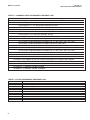
LIST OF TABLES
Table No.
1-1
1-2
1-3
1-4
5-1
6-1
6-2
7-1
7-2
Title
Commonly Used Accessories for Model 396R..................................................
Other Accessories for Model 396R ...................................................................
Commonly Used Accessories for Model 396RVP .............................................
Other Accessories for Model 396RVP...............................................................
ORP of Saturated Quinhydrone Solutions ........................................................
Ro and R1 Values for Temperature Compensation Elements...........................
Temperature vs. Resistance of Auto T.C. Elements ..........................................
Troubleshooting with Diagnostics......................................................................
Troubleshooting without Diagnostics.................................................................
i
Page
4
4
5
5
31
33
33
36
37
MODEL 396R pH/ORP
TABLE OF CONTENTS
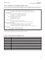
LIST OF FIGURES
Figure No.
1-1
2-1
2-2
2-3
2-4
2-5
2-6
2-7
2-8
3-1
3-2
3-3
3-4
3-5
3-6
3-7
3-8
3-9
3-10
3-11
3-12
3-13
3-14
3-15
4-1
4-2
4-3
4-4
4-5
4-6
4-7
4-8
4-9
4-10
4-11
4-12
4-13
4-14
4-15
4-16
4-17
4-18
4-19
4-20
4-21
6-1
6-2
Title
Cross Section Diagram of the TUpH Reference Technology ............................
Exploded View of Ball Valve Kit PN 23240-00 used with process connector .
PN 23166-00 (or PN 23166-01) ........................................................................
Typical Mounting Configurations for Model 396R .............................................
Typical Mounting Configurations for Model 396RVP.........................................
Dimensional Drawing — Model 396R with Optional Ball Valve PN 23765-00 ..
Dimensional Drawing — Model 396R with Optional Ball Valve PN 23240-00 ..
Dimensional Warning Label for Hemi Bulb Sensors and Sensor Diagram .......
Dimensional Drawing — Model 396RVP with Optional 1-1/2 inch Ball Valve ..
PN 23240-00 .....................................................................................................
Dimensional Drawing — Model 396RVP with Optional 1-1/4 inch Ball Valve ..
PN 23765-00 .....................................................................................................
Cable Preparation Instructions for Model 396R ................................................
Wiring Model 396R-54Model 54e, 81, 3081, 4081, 5081 pH/ORP ...................
Wiring Model 396R-54 with Remote Junction Box & Preamp (PN 23555-00) ........
Wiring Model 396R-50 for use with Remote Junction Box (PN 23309-03).............
Wiring Model 396R-54 for use with Remote Junction Box (PN 23309-04).............
Wiring Model 396R-54 to Model 1181 pH/ORP ...................................................
Wiring Model 396R-54 to Models 1054A/B pH/ORP, 2054 pH, and 2081 .............
Wiring Model 396R-54 to Model SCL-(P/Q).........................................................
Wiring Model 396R-54-61 to Model Xmt-P-HT-10....................................................
Wiring Model 396R-50/54-60 for use with Sensor Head J-Box.........................
Wiring Model 396R-54-61 for use with Sensor Head J-Box..............................
Wiring Model 396R-50 for use with J-Box (PN 23707-00) to Models 1181, .....
1050, 1060, 1030, 1023 pH Transmitters .........................................................
Wiring Model 396R-54 for use with J-Box (PN 23708-01) to Models 1054, .....
2054, and 2081 pH Transmitters.......................................................................
Wiring Model 396R-( )-54 to Model 1055-10-22-32 ..........................................
Wiring Model 396R-54-61 to Model 1055-10-22-32..........................................
Wire Functions and Pin Connections for Model 396RVP..................................
Wiring Model 396RVP to Model 81 ...................................................................
Wiring Model 396RVP to Model 1181 ...............................................................
Wiring Model 396RVP to Model 81 thru a Remote J-Box .................................
Wiring Model 396RVP to Models 1181/1050/1060/1003/1023 thru Remote J-Box
Wiring Model 396RVP to Model 2081 ...............................................................
Wiring Model 396RVP to Models 3081, 4081, and 5081 ..................................
Wiring Model 396RVP to Model 2081 thru a Remote J-Box .............................
Wiring Model 396RVP to Models 3081, 4081, and 5081 thru a Remote J-Box
Wiring Model 396RVP to Model 1054 ...............................................................
Wiring Model 396RVP to Models 1054A/B and 2054........................................
Wiring Model 396RVP to Model 1054 thru a Remote J-Box .............................
Wiring Model 396RVP to Models 1054A/B and 2054 thru a Remote J-Box......
Wiring Model 396RVP to Model 54 and 54e .....................................................
Wiring Model 396RVP to Model 54 thru a Remote J-Box .................................
Wiring Model 396RVP to Model 2700 ...............................................................
Wiring Model 396RVP to Model SCL-(P/Q) ......................................................
Wiring Model 396RVP to Model Xmt-P-HT-10 ..................................................
Wiring Model 396RVP to Model 1055pH/pH .....................................................
Wiring Model 396RVP to Model 1055pH/pH thru a Remote J-Box ...................
Wiring Model 396RVP to Model 1055-10-22-32................................................
Sensor Tube Replacement................................................................................
Male Connector Tightening Diagram.................................................................
ii
Page
1
7
8
8
9
10
11
12
13
14
15
15
16
16
17
17
18
18
19
19
20
21
22
22
23
24
24
24
24
25
25
25
25
26
26
26
26
27
27
27
27
28
28
28
29
35
35
MODEL 396R pH/ORP
SECTION 1.0
DESCRIPTION AND SPECIFICATIONS
SECTION 1.0
DESCRIPTION AND SPECIFICATIONS
1.1 FEATURES AND APPLICATIONS
The Model 396R and 396RVP Sensors are specifically
designed for improved life in harsh, dirty applications where
a separate sample stream is difficult to provide and greater
insertion depths are required. Model 396R is designed for
use with a 1-1/4 in. or 1-1/2 in. ball valve for hot tap installation. The Model 396R is constructed of molded polypropylene
housed in a titanium tube with EPDM seals to provide maximum chemical resistance2,3.
Model 396R also features a titanium solution ground for
advanced sensor diagnostics when used with the Models
1055, Xmt-P, 54e, 81, 3081, or 5081 pH/ORP Analyzer/
Transmitter. Advanced sensor diagnostics provide preventative maintenance by notifying the operator for replacement
and cleaning of an aged or fouled sensor for continuous
optimum performance.
The sensor also features a shrouded tip for protection from
breakage while allowing process to flow by the glass electrode for accurate and reliable pH measurement.
The Model 396R is available without an integral preamplifier
only and 15 ft or 9.5 in. of integral high quality 9 conductor
cable. The preamplifier must be housed in a remote location
or in a J-Box kit for attachment at the rear, cable end of the
sensor (order separately) or integral to the Analyzer/
Transmitter. The Model 396R is compatible with all
Rosemount Analytical and various other manufacturers
instruments.
The entire line of TUpH model sensors now incorporate
the new SILCORE1 technology contaminant barrier. This
triple-seal barrier prevents moisture and material impurities
from migrating to the pH sensor’s reference electrode’s metal
lead wire. By preventing these contaminants from compromising the integrity of the pH measurement, sensor life is
increased, especially at higher temperatures where
increased migrations occur. In addition, the SILCORE technology provides added protection against sensor failure due
to vibrations and shock by transferring damaging energy
away from the glass-to-metal seal.
Model 396RVP: Rosemount Analytical has recently released
Model 396RVP. This model has identical performance and
physical specifications to the Model 396R (see Section 1.2)
with the following exception: the Model 396RVP has a
Variopol (VP) connector on the back end of the sensor in
place of a cable.
1 Silcore is a trademark of Rosemount Analytical.
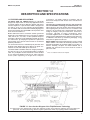
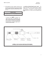
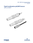
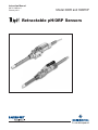
FIGURE 1-1. Cross Section Diagram of the TUpH Reference Technology
All TUpH sensors are designed with a large area reference junction, helical reference pathway, and an AccuGlass pH
glass bulb. This sensor technology ensures superior performance while only requiring minimal maintenance.
1
MODEL 396R pH/ORP
1.2
SECTION 1.0
DESCRIPTION AND SPECIFICATIONS
PERFORMANCE AND PHYSICAL SPECIFICATIONS
MODEL 396R
MODEL 396RVP
Measured Range:
Measured Range:
ORP: -1500 to 1500mV
pH: 0 to 14
Percent Linearity Over pH Range:
ORP: -1500 to 1500mV
pH: 0 to 14
Available pH glass types: GPLR hemi bulb or flat bulb
Hemi Bulb
Flat Bulb
0-2 pH
94%
93%
2-12 pH
99%
98%
12-13 pH
97%
95%
13-14 pH
92%
—
Wetted Materials: Polypropylene, EPDM, titanium,
glass, (platinum: ORP only)
Process Connections: 1-1/2 or 1-1/4 in. with ball
valve, 1 in. without ball valve
Cable: Integral 15 ft or 9.5 in. 9 conductor cable
except option 60 (9.5 in. coaxial cable with
BNC) Recommended Interconnect (PN
9200273)
Maximum Process Pressure and Temperature:
Hemi bulb: 150 psig (1136 kPa abs) at 212°F
(100°C )
Flat bulb: 100 psig (790 kPa abs) at 212°F
(100°C )
Maximum Pressure at Retraction or Insertion:
Code 21: 64 psig (542 kPa abs)
Code 25: 35 psig (343 kPa abs)
Minimum Conductivity: 100 µS/cm
Weight/Shipping Weight:
Sensor:
Code 21: 2.0 lb/3.0 lb (.9 kg/1.40 kg)
Code 25: 3.0 lb/4.0 lb (1.40 kg/1.80 kg)
Ball Valve:
PN 23240-00; 5 lb/7 lb (2.25 kg /3.20 kg)
PN 23634-00 8 lb/10 lb (3.65 kg/4.55 kg)
J-Box: 3 lb/4 lb (1.40 kg/1.80 kg)
2
Wetted Materials: Polypropylene, EPDM, titanium,
glass, (platinum: ORP only)
Process Connections: none, use 1-inch process connector or ball valve kit (1-1/2 inch or 1-1/4 inch)
Temperature Range: 0 to 100C (32 to 212F)
Pressure Range (hemi bulb): 100-1136 kPa abs
(0-150 psig)
Pressure Range (flat bulb): 100-790 kPa abs
(0-100 psig)
Maximum Pressure at Retraction or Insertion:
Code 21: 64 psig (542 kPa abs)
Code 25: 35 psig (343 kPa abs)
Minimum Conductivity: 75 µS/cm, nominal
Preamplifier options: remote
Weight/Shipping Weight:
Sensor: Code 21: 2.0 lb/ 3.0 lb (.9 kg/1.40 kg)
Code 25: 3.0 lb/4.0 lb (1.40 kg/1.80 kg)
Ball Valve: PN 23240-00; 5 lb/7 lb (2.25 kg /3.20 kg)
MODEL 396R pH/ORP
SECTION 1.0
DESCRIPTION AND SPECIFICATIONS
1.3 ORDERING INFORMATION
The Model 396R Sensor is housed in a titanium tube, with a polypropylene reference junction and titanium solution ground for use with a ball valve (order separately) for hot tap applications. The sensor is available with either
a hemi or flat glass pH electrode and features a shrouded glass/platinum electrode and PT100 or 3K temperature
compensation. The 396R is available with 9.5 in. or 15 ft of integral cable. The 396R sensor is not available with
a preamp. Junction box kits with preamps must be ordered separately if the analyzer/transmitter does not have
an integral preamp within 15 ft. of the probe. Process connector and ball valve assemblies must also be ordered
separately.
MODEL
396R
TUpH RETRACTABLE pH SENSOR
CODE
10
12
13
MEASURING ELECTRODE TYPE (Required Selection)
GPLR hemi glass, General Purpose Low Resistivity
ORP
GPLR flat glass, General Purpose Low Resistivity
CODE
21
25
SENSOR LENGTH
21 in. Titanium Tube
36 in. Titanium Tube
CODE
50
54
ANALYZER/TC COMPATIBILITY (Required Selection)
For Models 1181 (3K TC)
For Models 1054B, 1055, 2081,54e, 81, 3081, 4081, 5081, Xmt, SCL-(P/Q), (PT 100 RTD)
CODE
60
OPTIONAL OPTIONS
9.5 in. Cable with BNC (for use with Model 1181, 1054 series, 2054, 2081 Sensor Head J-Boxes)
61
396R -
9.5 in. Cable no BNC (Not Valid w/Option 50) (for use with Model 54e, 1055, 81, 3081, 4081, 5081, Xmt
Sensor Head J-Boxes)
10
- 21
- 54
EXAMPLE
The Model 396RVP ball valve retractable sensor features a gel-filled electrolyte solution with the large area,
coating resistant TUpH polypropylene reference junction and a standard hemi or optional flat glass bulb. Model
396RVP is housed in a Titanium sensor tube and can be mounted directly into the process using a 1 in. MNPT
threaded process connector and a ball valve assembly kit (both ordered separately). It is offered with the watertight Variopol sensor-to-cable connector and uses the mating connector cable (ordered separately). Also available is a choice of temperature element, 3 K Balco or Pt 100 RTD. A remote preamplifier found in the
analyzer/transmitter or in a junction box (ordered separately) must be used with this sensor for a reliable signal
transmission.
MODEL
396RVP TUpH RETRACTABLE pH/ORP SENSOR
CODE
10
12
13
MEASURING ELECTRODE TYPE (Required Selection)
Hemi bulb, General Purpose Low Resistivity
ORP
Flat, GPLR glass
CODE
21
25
SENSOR LENGTH (Required Selection)
21 in. Titanium Tube
36 in. Titanium Tube
CODE
50
54
ANALYZER/TC COMPATIBILITY (Required Selection)
For Models 1181 (3K TC)
For Models 1054B, 1055, 2081,54e, 81, 3081, 4081, 5081, Xmt, SCL-(P/Q), (Pt 100 RTD)
396RVP -
10
- 21
- 54
EXAMPLE
3
MODEL 396R pH/ORP
SECTION 1.0
DESCRIPTION AND SPECIFICATIONS
TABLE 1-1. COMMONLY USED ACCESSORIES FOR MODEL 396R
For first time installations, Rosemount Analytical recommends using the following guide
1. Retractable Mounting
A. Choose one (required for all first time installations):
PN 23166-00, 1 in. x 1 in. NPT process connector, 316 SST
PN 23166-01, 1 in. x 1 in. NPT process connector, Titanium
B. Choose one:
PN 23240-00, 1-1/2 in. ball valve assembly, 316 SST
PN 23765-00, 1-1/4 in. ball valve assembly, 316 SST
2. Junction Boxes (Optional; Choose either Sensor Head or Remote)
A. Sensor Head Junction Boxes (used with options -60 or -61 sensor) - Choose one:
PN 23709-00; includes preamplifier for Models 54e, 81, 3081, 4081, 5081, Xmt, 1055
PN 23708-01; includes preamplifier for Models 1054 series, 2054, 2081
PN 23707-00; includes preamplifier for Model 1181
B. Remote Junction Boxes (used with standard 15 ft. cable length sensor) - Choose one:
PN 23555-00; includes preamplifier for Models 54e, 81, 3081, 4081, 5081, Xmt, 1055
PN 23309-03; includes preamplifier for Model 1181
PN 23309-04; includes preamplifier for Models 1054 series, 2054, 2081
3. BNC Adapter - Choose one:
PN 9120516, BNC Adapter for use with remote junction boxes PN’s 23309-03 and 23309-04
Order option -60 (standard with BNC connector) for PN 23707-00 or 23708-01 sensor head junction boxes
4. Extension Cables - Choose one:
PN 23646-01, 11 conductor, shielded, prepped
PN 9200273, 11 conductor, shielded, unprepped
TABLE 1-2. OTHER ACCESSORIES FOR MODEL 396R
PART
22698-00
22698-02
22698-03
23550-00
9550167
9210012
9210013
9210014
22743-01
22744-01
23557-00
4
DESCRIPTION
Preamplifier plug-in for J-box, for Model 1003,
Preamplifier plug-in for J-box, for Models 1181/1050
Preamplifier plug-in for J-box, for Models 1054A/B, 2054, 2081
Remote Junction box with extension board
O-ring, 2-214, EPDM for process connector
Buffer solution, 4.01 pH, 16 oz
Buffer solution, 6.86 pH, 16 oz
Buffer solution, 9.18 pH, 16 oz
Pt100 preamp for Model 1181
3K Preamp for Model 1181
Preamplifier for junction box for Models 1055, 54e, 81, 3081, 4081, 5081, Xmt
MODEL 396R pH/ORP
SECTION 1.0
DESCRIPTION AND SPECIFICATIONS
TABLE 1-3. COMMONLY USED ACCESSORIES FOR MODEL 396RVP
FOR FIRST TIME 396RVP AND 398RVP INSTALLATIONS, ROSEMOUNT ANALYTICAL RECOMMENDS USING THE FOLLOWING GUIDE:
1. Variopol Cable (required for all first time installations)
Choose one: PN 23645-06, 15 ft cable with mating VP connector, prepped with BNC on analyzer end
PN 23645-07, 15 ft cable with mating VP connector, prepped without BNC on analyzer end*
2. Retractable Mounting
1A. Choose one (required for all first time installations, except as noted):
PN 23166-00 1 in. x 1 in. NPT process connector, 316 SST
PN 23166-01 1 in. x 1 in. NPT process connector, Titanium
Choose one (optional process connector o-rings):
1
®
PN 9550220, Kalrez o-ring, 2-214
1
®
PN 9550099, Viton o-ring, 2-214
1B. Choose one:
PN 23240-00 1-1/2 in. ball valve assembly, 316 SST
PN 23765-00 1-1/4 in. ball valve assembly, 316 SST (process connector not needed)
3. Remote Junction Boxes (Optional)
Choose one: PN 23555-00 includes preamplifier for Models 54e, 81, 3081, 4081, 1055, 5081, Xmt
PN 23309-03 and PN 22698-02 plug-in preamplifier for Model 1181Analyzer
PN 23309-04 and PN 22698-03 plug-in preamplifier for Models 1054 series and 2081 Analyzers
4. Extension cables
Choose one: PN 23646-01, 11 conductor, shielded, prepped
PN 9200273, 11 conductor, shielded, unprepped
* Used for connections to Models 1181, 2081, 54e, 81, 3081, 4081, 5081, Xmt, 1055, and remote junction box PN 23555-00.
2 kalrez and Viton are registered trademarks of DuPont Performance Elastomers.
TABLE 1-4. OTHER ACCESSORIES FOR MODEL 396RVP
PART
22698-00
22698-02
22698-03
22743-01
22744-01
23557-00
33046-00
9310096
9210012
9210013
9210014
R508-80Z
9550167
12707-00
DESCRIPTION
Preamplifier plug-in for junction box, for Model 1003,
Preamplifier plug-in for junction box, for Models 1181, 1050
Preamplifier plug-in for junction box, for Models 1054B, 2081
Pt100 preamplifier for Model 1181
3K Preamplifier for Model 1181
Preamplifier for junction box for Models 54e, 81, 3081, 4081, 5081, Xmt, 1055
Ferrule, 1 in., split 316SS
Nut, swage, 1 in. 316SST
Buffer solution, 4.01 pH, 16 oz
Buffer solution, 6.86 pH, 16 oz
Buffer solution, 9.18 pH, 16oz
ORP solution, 460 mv ± 10 at 20°C
EPDM O-ring for Process Connector (PN 23166-00 or 23166-01)
Jet Spray Cleaner
5
MODEL 396R pH/ORP
SECTION 2.0
INSTALLATION
SECTION 2.0
INSTALLATION
2.1 UNPACKING AND INSPECTION. Inspect the outside
of the carton for any damage. If damage is detected,
contact the carrier immediately. Inspect the instrument
and hardware. Make sure all items in the packing list
are present and in good condition. Notify the factory if
any part is missing.
NOTE
If the sensor is to be stored, the protective
boot should be filled with either KCl electrolyte solution or pH 4.0 buffer solution
and replaced on sensor tip until ready to
use.
NOTE
Save the original packing cartons and
materials as most carriers require proof of
damage due to mishandling, etc. Also, if it
is necessary to return the instrument to the
factory, you must pack the instrument in the
same manner as it was received. Refer to
Section 8.0 for instructions.
WARNING
The sensor must be mounted within 10-90 degrees of
the horizontal with the tip pointed downward, thus
keeping air bubbles off of the pH sensitive glass bulb.
Bubbles settled on the glass bulb disrupt the electrical
continuity between the pH sensitive glass and the silver/silver chloride measuring element.
If the retraction version is to be installed without a ball
valve follow the installation procedure for insertion
service (Section 2.2.2). Perform the following steps for
sensor installation through a ball valve:
2.2.1 INSTALLATION THROUGH BALL VALVE.
1. Carefully remove the liquid filled rubber boot which
protects the glass electrode and keeps the liquid
junction wet during shipping and storage. Discard
the liquid and boot. Make sure the lubricated
O-ring is in place in the groove inside the male
connector on the sensor body.
CAUTION
Buffer solution, in the protective boot, may cause skin
or eye irritation.
2.
Glass electrode must be wetted at all times (in storage
and in line) to maximize sensor life.
3.
2.2 MECHANICAL INSTALLATION. The Model 396R
Sensor may be installed through a weldalet or in a pipe
tee or “Y”, as shown in Figure 2-1, when used with a
ball valve. Insert the end of the sensor to a depth
sufficient to ensure that the glass bulb is continuously
wetted by the process fluid. The Model 396R can also
be inserted directly into the process without the use of
a ball valve for applications not requiring continuous
operation during sensor maintenance.
4.
The sensor must be captured by the valve assembly
and the male connector so that it cannot be blown
free by process pressure if mishandled during insertion or retraction.
5.
6
Pull back hard on the sensor assembly, as if trying
to remove the sensor, to be certain that the sensor
cannot come free of the ball valve assembly. The
built-in retraction stop will butt against the shoulder of the male connector if properly installed.
CAUTION
CAUTION
Allow sufficient room for safe retraction and insertion of
the sensor. Personnel should have room for stable footing while performing removal or insertion of the sensor.
With the male connector on the sensor’s body,
insert the sensor into the ball valve until it gently
touches the closed valve. The molded electrode
guard will protect the glass bulb from breakage.
Thread the male connector body tightly into the
ball valve assembly. DO NOT tighten the hex nut
on the male connector body; doing so would not
allow the sensor to be inserted through the ball
valve.
After confirming that the sensor assembly is properly secured by the valve assembly, the valve may
be opened and the sensor positioned into the
process at the desired depth and orientation.
MODEL 396R pH/ORP
6.
SECTION 2.0
INSTALLATION
While holding the sensor in position, tighten the hex
nut of the male connector to firmly secure the sensor
in place. When the hex nut is tightened, the Teflon
ferrule inside the compression fitting clamps the sensor tube.
2.2.2 INSTALLATION WITHOUT A BALL VALVE. The
Model 396R Sensor may be installed through a weldalet
or pipe tee or “Y” when used with a process connector
(PN 23166-00 or 23166-01). The sensor should be
installed within 80° of vertical, with the electrode facing
down.
CAUTION
Over tightening the hex nut may damage the ferrule.
NOTE
A stainless steel ferrule is available if the
Teflon ferrule does not inadequately grip.
When using the metallic ferrule, care must be
taken to avoid over tightening and damaging
the sensor tube. If the male connector leaks
during insertion or retraction, replace the Oring in the male connector.
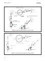
FIGURE 2-1. Exploded View of Ball Valve Kit PN 23240-00
used with process connector PN 23166-00 (or PN 23166-01)
7
MODEL 396R pH/ORP
SECTION 2.0
INSTALLATION
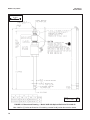
JUNCTION BOX IS OPTIONAL
FIGURE 2-2. Typical Mounting Configurations for Model 396R
FIGURE 2-3. Typical Mounting Configurations for Model 396RVP
8
MODEL 396R pH/ORP
SECTION 2.0
INSTALLATION
INCH
MILLIMETER
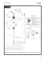
FIGURE 2-4. Dimensional Drawing — Model 396R with Optional Ball Valve PN 23765-00
Note: Add five (5) inches to dimension A if mounting a sensor head junction box onto the sensor.
9
MODEL 396R pH/ORP
SECTION 2.0
INSTALLATION
WHEN INCH AND METRIC DIMS
ARE GIVEN
MILLIMETER
INCH
DWG. NO.
40396R05
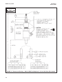
FIGURE 2-5. Dimensional Drawing — Model 396R with Optional Ball Valve PN 23240-00
Note: Add five (5) inches to dimension A if mounting a sensor head junction box onto the sensor.
10
REV.
D
MODEL 396R pH/ORP
SECTION 2.0
INSTALLATION
MILLIMETER
INCH
4.920
Front Side 396R-21
Note: Retraction Pressure
2.25
36”
36”
Back Side 396R
Front Side 396R-25
Note: Retraction Pressure
A
MM / IN
548.64 / 21.60
916.94 / 36.10
OPTION
21
25
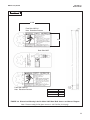
FIGURE 2-6. Dimensional Warning Label for Model 396R Hemi Bulb Sensors and Sensor Diagram
Note: Pressure rating for flat glass sensors is 100-790 kPa (0-100 psig).
11
MODEL 396R pH/ORP
SECTION 2.0
INSTALLATION
WHEN INCH AND METRIC DIMS
ARE GIVEN
MILLIMETER
INCH
FIGURE 2-7. Dimensional Drawing — Model 396RVP with Optional 1-1/2 inch Ball Valve PN 23240-00
12
MODEL 396R pH/ORP
SECTION 2.0
INSTALLATION
INCH
MILLIMETER
FIGURE 2-8. Dimensional Drawing — Model 396RVP with Optional 1-1/4 inch Ball Valve PN 23765-00
13
MODEL 396R pH/ORP
SECTION 3.0
WIRING MODEL 396R
SECTION 3.0
WIRING MODEL 396R
WIRING MODEL 396R.
Make electrical connections as shown on Figures 3-1
through 3-15 using the following guidelines. For wiring
Model 396RVP, see Section 4.0.
1.
Pay particular attention to the analyzer or transmitter model number when following details on the
wiring diagrams to ensure that the connections are
made to the proper terminals.
2.
Use Rosemount custom cable Part Number
9200273 for interconnect.
3.
The maximum distance from the sensor to the
analyzer is 15 ft without an integral preamplifier.
4.
Signal cable should be run in a dedicated conduit
and should be kept away from AC power lines.
NOTE
For maximum EMI/RFI protection when wiring
from the sensor to the junction box, the outer
braid of the sensor should be connected to the
outer braided shield of the extension cable.
The outer braid of the extension cable to the
instrument must be terminated at earth ground
or by using an appropriate metal cable gland
fitting, that provides a secure connection to the
instrument cable.
WARNING: IF INNER BLACK
CONDUCTIVE SHEATH IS IN
CONTACT WITH THE EXPOSED
LEADS, OR IS NOT PREPARED
PROPERLY, IT MAY CAUSE AN
ELECTRICAL SHORT.
DWG. NO.
40396R24
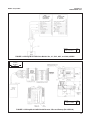
FIGURE 3-1. Cable Preparation Instructions (PN 9200274)
14
REV.
A
MODEL 396R pH/ORP
SECTION 3.0
WIRING MODEL 396R
DWG. NO.
40396R07
REV.
D
FIGURE 3-2. Wiring Model 396R-54 to Models 54e, 81, 3081, 4081, and 5081 pH/ORP
WHEN INCH AND METRIC DIMS
ARE GIVEN
MILLIMETER
INCH
MODELS
54e, 81, 3081,
4081, 5081
DWG. NO.
40396R08
REV.
B
FIGURE 3-3. Wiring Model 396R-54 with Remote J-Box and Preamp (PN 23555-00)
15
MODEL 396R pH/ORP
SECTION 3.0
WIRING MODEL 396R
DANGER:
Do not connect sensor
cable to power lines.
Serious injury may result.
1
PREP ORANGE WIRE FOR PREAMP
WITH BNC ADAPTER (PN 9120516).
DWG. NO.
40396R011
REV.
A
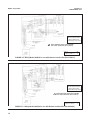
FIGURE 3-4. Wiring Model 396R-50 for use with Remote Junction Box (PN 23309-03)
DANGER:
Do not connect sensor
cable to power lines.
Serious injury may result.
1
PREP ORANGE WIRE FOR PREAMP
WITH BNC ADAPTER (PN 9120516).
DWG. NO.
40396R012
FIGURE 3-5. Wiring Model 396R-54 for use with Remote Junction Box (PN 23309-04)
16
REV.
A
MODEL 396R pH/ORP
SECTION 3.0
WIRING MODEL 396R
DWG. NO.
REV.
40396R09
A
FIGURE 3-6. Wiring Model 396R-50/54 to Model 1181 pH/ORP
1
PREP ORANGE WIRE FOR PREAMP
WITH BNC ADAPTER (PN 9120516).
DWG. NO.
REV.
40396R010
A
FIGURE 3-7. Wiring Model 396R-54 to Models 1054A/B pH/ORP, 2054 pH, and 2081 pH/ORP
17
MODEL 396R pH/ORP
SECTION 3.0
WIRING MODEL 396R
DWG. NO.
40396R13
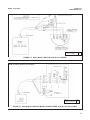
FIGURE 3-8. Wiring Model 396R-54 to Model SCL-(P/Q)
FIGURE 3-9. Wiring Model 396R-54-61 to Model Xmt-P-XX-10
18
REV.
A
MODEL 396R pH/ORP
SECTION 3.0
WIRING MODEL 396R
WHEN INCH AND METRIC DIMS
ARE GIVEN
MILLIMETER
INCH
DWG. NO.
REV.
40396R21/22 C/C
FIGURE 3-10. Wiring Model 396R-50/54-60 for use with Sensor Head
J-Boxes to Models 1181, 1054 Series, 2054, 2081
MODELS
54e, 81,
3081,
4081,
5081
DWG. NO.
40396R06
REV.
C
FIGURE 3-11. Wiring Model 396R-54-61 for use with Sensor Head J-Box
to Models 54e, 81, 3081, 4081, and 5081
19
MODEL 396R pH/ORP
SECTION 3.0
WIRING MODEL 396R
MILLIMETER
INCH
DWG. NO.
40396R21
FIGURE 3-12. Wiring Model 396R-50 for use with J-Box (PN 23707-00)
to Models 1181, 1050, 1060, 1030, and 1023 pH Transmitters
20
REV.
C
MODEL 396R pH/ORP
SECTION 3.0
WIRING MODEL 396R
DWG. NO.
40396R22
REV.
C
FIGURE 3-13. Wiring Model 396R-54 for use with J-Box (PN 23708-01) to Models 1054 Series, 2054, and
2081 pH Transmitters
21
MODEL 396R pH/ORP
SECTION 3.0
WIRING MODEL 396R
FIGURE 3-14. Wiring Model 396R-( )-54 to Model 1055-10-22-32
FIGURE 3-15. Wiring Model 396R-54-61 to Model 1055-10-22-32
22
MODEL 396R pH/ORP
SECTION 4.0
WIRING MODEL 396RVP
SECTION 4.0
WIRING MODEL 396RVP
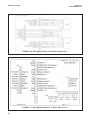
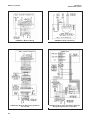
WIRING MODEL 396RVP.
Make electrical connections as shown on Figures 4-1
through 4-21 using the following guidelines. For wiring
Model 396R, see Section 3.0.
1.
Pay particular attention to the analyzer or transmitter model number when following details on the
wiring diagrams to ensure that the connections are
made to the proper terminals.
2.
The Model 396RVP uses a mating VP cable. The
cable part numbers are 23645-06 and 23645-07.
See attached wiring sheet for wire functions of the
cables and wiring diagrams to various analyzers.
3.
The maximum distance from the sensor to the
analyzer is 15 ft without an integral preamplifier.
4.
Signal cable should be run in a dedicated conduit
and should be kept away from AC power lines.
NOTE
For maximum EMI/RFI protection when wiring
from the sensor to the junction box, the outer
braid of the sensor should be connected to the
outer braided shield of the extension cable.
The outer braid of the extension cable to the
instrument must be terminated at earth ground
or by using an appropriate metal cable gland
fitting, that provides a secure connection to the
instrument cable.
FIGURE 4-1. Wire Functions for Mating Variopol Cable used with Model 396PVP
23
MODEL 396R pH/ORP
24
SECTION 4.0
WIRING MODEL 396RVP
FIGURE 4-2. Model 81 Wiring
FIGURE 4-3. Model 1181 Wiring
FIGURE 4-4. Model 81 Wiring through Remote
Junction Box
FIGURE 4-5. Model 1181, 1050/1060, & 1003/1023
Wiring through Remote Junction Box
MODEL 396R pH/ORP
SECTION 4.0
WIRING MODEL 396RVP
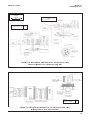
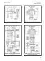
FIGURE 4-6. Model 2081 Wiring
FIGURE 4-7. Model 3081, 4081, and 5081 Wiring
FIGURE 4-8. Model 2081 Wiring through Remote
Junction Box
FIGURE 4-9. Model 3081, 4081, and 5081 Wiring
through Remote Junction Box
25
MODEL 396R pH/ORP
SECTION 4.0
WIRING MODEL 396RVP
FIGURE 4-10. Model 1054 Wiring
FIGURE 4-11. Model 1054A/B & 2054 Wiring
FIGURE 4-12. Model 1054 Wiring through a Remote
Junction Box
FIGURE 4-13. Model 1054A/B & 2054 Wiring through
a Remote Junction Box
26
MODEL 396R pH/ORP
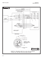
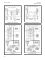
FIGURE 4-14. Model 54/54e Wiring
SECTION 4.0
WIRING MODEL 396RVP
FIGURE 4-15. Model 54 Wiring through Remote Junction Box
FIGURE 4-17. Model SCL-(P/Q) Wiring
FIGURE 4-16. Model 2700 Wiring
27
MODEL 396R pH/ORP
SECTION 4.0
WIRING MODEL 396RVP
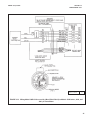
FIGURE 4-18. Model Xmt-P-XX-10 Wiring
FIGURE 4-19. Model 1055pH/pH Wiring
FIGURE 4-20. Model 1055pH/pH Wiring through Remote Junction Boxes
28
MODEL 396R pH/ORP
SECTION 4.0
WIRING MODEL 396RVP
VARIOPOL CABLE
PN 23645-07
FIGURE 4-21. Model 1055-10-22-32 Wiring
29
MODEL 396R pH/ORP
SECTION 5.0
START UP AND CALIBRATION
SECTION 5.0
START UP AND CALIBRATION
5.1 START UP. To obtain best accuracy, the sensor
must be calibrated as a loop with the analyzer. Please
refer to the respective analyzer/transmitter instruction
manual for proper calibration procedures.
5.2 396R pH CALIBRATION
1. After a temporary connection is established
between the sensor and the instrument, a buffer
calibration may be performed.
2. Consult appropriate pH/ORP analyzer or
transmitter instruction manual for specific
calibration and standardization procedures or see
below for recommended two point buffer
calibration procedure.
5.2.1 Recommended two point buffer calibration
procedure:
Select two stable buffer solutions, preferably pH 4.0
and 10.0 (pH buffers other than pH 4.0 and pH 10.0
can be used as long as the pH values are at least two
pH units apart).
Note: A pH 7 buffer solution reads a mV value
of approx. zero, and pH buffers read approx.
+/- 59.1 mV for each pH unit above or below
pH 7. Check the pH buffer manufacturer specifications for millivolt values at various temperatures since it may affect the actual value of
the buffer solution mV/pH value.
1. Immerse sensor in the first buffer solution. Allow
sensor to adjust to the buffer temperature (to avoid
errors due to temperature differences between the
buffer solution and sensor temperature) and wait
for reading to stabilize. Value of buffer can now be
acknowledged by analyzer/transmitter
2. Once the first buffer has been acknowledged by
the analyzer/transmitter, rinse the buffer solution off
of the sensor with distilled or deionized water.
30
3. Repeat steps 1 and 2 using the second buffer
solution.
4. Once the analyzer/transmitter has acknowledged
both buffer solutions, a sensor slope (mV/pH) is
established (the slope value can be found within
the analyzer/transmitter).
5. The slope value should read about 59.1 mV/pH for
a new sensor and will decrease over time to
approximately 47 - 49 mV/pH. Once the slope
reads below the 47-49 mV/pH range, a new sensor
should be installed to maintain accurate readings.
5.2.2 Recommended pH Sensor Standardization
For maximum accuracy, the sensor can be standardized on-line or with a process grab sample after a
buffer calibration has been performed and the sensor
has been conditioned to the process. Standardization
accounts for the sensor junction potential and other
interferences. Standardization will not change the sensor’s slope but will simply adjust the analyzers reading
to match that of the known process pH.
1. While obtaining a process solution sample (it is
recommended that the sample is taken close to
the sensor), record the pH value that is shown on
the analyzer/transmitter display.
2. Measure and record the pH of the process solution
sample with a another temperature compensated,
calibrated pH instrument. For best results,
standardization should be performed at the
process temperature.
3. Adjust the analyzer/transmitter value to the
standardized value.
MODEL 396R pH/ORP
SECTION 5.0
START UP AND CALIBRATION
5.3 396R ORP CALIBRATION. An ORP loop is best
calibrated using an ORP standard solution. Most industrial applications have a number of ORP reactions
occurring in sequence or simultaneously. There can be
several components that are oxidized or reduced by
the reagents that are used. Theoretically, the ORP
potential is absolute because it is the result of the oxidation-reduction equilibrium. However, the actual
measured potential is dependent on many factors,
including the condition of the surface of the ORP platinum electrode. Therefore, the sensor should be
allowed 1-2 hours to become “conditioned” to the
stream when first set-up or after being cleaned.
3.
Immerse the sensor in the standard solution. Allow
1-2 minutes for the ORP sensor to stabilize.
4.
Adjust the standardize control of the instrument to
the solution value shown in Table 5-1. The resulting potentials, measured with a clean platinum
electrode and saturated KCl/AgCl reference electrode, should be within ±20 millivolts of the value
shown in Table 5-1. Solution temperature must be
noted to insure accurate interpretation of results.
The ORP value of saturated quinhydrone solution
is not stable over long periods of time. Therefore,
these standards should be made up fresh each
time they are used.
5.3.1 ORP Calibration Procedure
5.
Remove the sensor from the buffer, rinse and
install in the process.
1.
Make a temporary electrical connection between
the sensor and the instrument.
2.
Obtain a ORP standard solution (PN R508-8oz) or
one can be made quite simply by adding a few
crystals of quinhydrone to either pH 4 or pH 7
buffer. Quinhydrone is only slightly soluble; therefore, only a few crystals will be required.
TABLE 5-1
ORP of Saturated Quinhydrone Solution
pH 4
pH 7
TEMPERATURE °C
20
25
30
20
25
30
Millivolt Potential
268
264
260
94
87
80
31
MODEL 396R pH/ORP
SECTION 6.0
MAINTENANCE
SECTION 6.0
MAINTENANCE
6.1 Maintenance. The Model 396R Sensor is a disposal type sensor and therefore requires minimum
maintenance. The sensor should be removed from the
process periodically and checked in buffer solutions. If
the sensor will not calibrate, refer to your
analyzer/transmitters instruction manual for proper test
procedures. If the sensor has failed, it should be discarded and replaced.
6.2 Sensor Removal. Please refer to the appropriate
paragraph for instructions regarding removal of the
sensor for periodic maintenance.
6.2.1 Retractable Version.
WARNING
4.
WARNING
Before removing the sensor from the ball valve, be
absolutely certain that the ball valve is fully closed.
Leakage from the male connector threads may indicate
that the male connector is still under pressure. Leakage
through a partially open valve could be hazardous, however with the ball valve closed, some residual process
fluid may leak from the connector's pipe threads.
5.
System pressure may cause the sensor to blow out with
great force unless care is taken during removal. Make
sure the following steps are adhered to.
A. Model 396R-21 (21” tube)
1. Be certain system pressure at the sensor is below
64 psig (542 kPa) before proceeding with the
retraction. It is also recommended that the personnel wear a face shield and have a stable footing. Refer to Figure 6-1. Push in on the sensor
end or the top of the J-box and slowly loosen the
hex nut (B) of the process end male connector (A).
B. Model 396R-25 (36” tube)
2. Be certain that pressure at the sensor is below 35
psig (343 KPa) before proceeding with the retraction. It is also recommended that the personnel
wear a face shield and have a stable footing.
Refer to Figure 6-1. Push in on the sensor end or
the top of the J-box and slowly loosen the hex nut
(B) of the process end male connector (A).
CAUTION
Do not remove nut at this time.
3.
When the hex nut is loose enough, slowly ease
the sensor back completely until the retraction
stop collar is reached.
CAUTION
Failure to withdraw the sensor completely may result
in damage to the sensor when the valve is closed.
32
Close the ball valve slowly. If there is resistance,
the valve may be hitting the sensor. Double check
that the sensor has been retracted to the retraction stop collar.
The Male Connector Body (A) may now be completely unthreaded from the reducing coupling and
the sensor removed for servicing.
CAUTION
If the male connector leaks during insertion or retraction, replace the O-ring (PN 9550099) in the male
connector A.
6.3 pH Electrode Cleaning. If the electrode is coated
or dirty, it may be cleaned as follows:
1.
Remove the sensor from process as instructed in
Section 6.2.
2.
Wipe the glass bulb with a soft, clean, lint free
cloth or tissue. If this does not remove the dirt or
coating, proceed to step 3. If the sensor appears
to be clean, go to step 5.
3.
Wash the glass bulb in a strong detergent solution
and thoroughly rinse with tap water. If the bulb still
appears to have a coating, proceed to step 4.
CAUTION
The solution used in the following step is an acid and
should be handled with care. Follow the directions of
the acid manufacturer. Wear the proper protective
equipment. Do not let the solution come in contact
with skin or clothing. If contact with the skin is made,
immediately rinse with clean water.
MODEL 396R pH/ORP
4.
5.
SECTION 6.0
MAINTENANCE
TABLE 6-2
TEMPERATURE vs RESISTANCE OF AUTO
T.C. ELEMENTS
Following the caution above, wash the glass bulb
in dilute 5% hydrochloric acid solution and then
rinse it thoroughly in tap water. Replace the sensor if it cannot be cleaned. If the glass bulb
appears clean, proceed to step 5.
Temperature °C
Buffer calibrate the sensor (Refer to Section 5.0). If
the sensor appears to respond sluggishly to pH
change, soaking it overnight in a weak acid solution
(5% hydrochloric acid) may improve its response. Be
sure to follow the CAUTION above and to rinse the
sensor’s tip thoroughly with tap water. If the sensor
will not calibrate, it must be replaced.
6.4 Cleaning Platinum Electrode. The electrode is
never exposed to these undesirable compounds. In the
event poisoning is suspected, the electrode can be
restored to normal operation by simply cleaning the platinum electrode with baking soda. Polish it by rubbing it
with a damp paper towel and baking soda until a bright,
shiny appearance is attained.
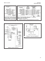
6.5 Automatic Temperature Compensator. The temperature compensator element is temperature sensitive and can be checked with an ohmmeter.
Resistance increases with temperature.
The 3K element will read 3000 ohms ± 1% at 25°C
(77°F) and a Pt-100 will read 110 ohms. Resistance
varies with temperature for a 3K and Pt-100 element
and can be determined according to Table 6-2 or the
following formula:
0
10
20
25
30
40
50
60
70
80
90
100
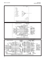
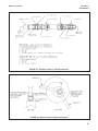
6.6 Sensor Tube Replacement When Used With A
Sensor Head Junction Box. Replacement of the
retraction versions sensor tube assembly involves the
removal and installation of two sets of male connectors:
One at the process end of the sensor, and the other at
the junction box end (See Figures 6-1, 6-2). Refer to
Section 6.2 for proper removal of the sensor from
process.
1.
Remove sensor from process before proceeding.
The junction box with attached male connector
must be recovered from the old sensor for reuse.
Unscrew the junction box cover and set aside.
Disconnect electrical connections from printed circuit board inside junction box. Disconnect BNC
connector to preamp. Unscrew hex nut (D) from
male connector body (C). Separate junction box
from used sensor. Set aside.
2.
Pry off split ferrule from sensor and set aside for
reuse. Remove hex nut (D) and set aside for
reuse. Check that the internal O-ring is in place in
the male connector body (C) attached to the junction box.
3.
Remove hex nut (B) from male connector body (A)
at process end of sensor and set aside. Slide the
Teflon ferrule and the male connector off sensor in
the direction of junction box and set
RT=Ro [l+R1 (T-20)]
Where RT = Resistance
T = Temperature in °C
Refer to Table 6-1 for Ro and R1 values:
TABLE 6-1
Ro and R1 VALUES FOR TEMPERATURE
COMPENSATION ELEMENTS
Temperature
Compensation Element
Ro
R1
3K
PT-100
2934
107.7
.0045
.00385
Resistance
(Ohms) ±1%
3K
PT-100
2670
100.0
2802
103.8
2934
107.7
3000
109.6
3066
111.5
3198
115.4
3330
119.2
3462
123.1
3594
126.9
3726
130.8
3858
134.6
3990
138.5
NOTE
If stainless steel ferrule was used, male
connector body (A) will have to be discarded with the sensor tube.
33
MODEL 396R pH/ORP
4.
SECTION 6.0
MAINTENANCE
Discard used O-ring from male connector body
(A). Coat new O-ring with a thin film of the O-ring
lubricant provided. Position it in the machined Oring groove in place of the discarded O-ring.
CAUTION
Make sure lubricant does not contact any part of the
sensor tip particularly the glass bulb.
5.
6.
7.
Cover the 1" MNPT pipe threads of the male connector body (A) with Teflon tape (not provided) to
protect them from galling during reinstallation.
Pass the wires from the new sensor through the
process end male connector (A). Make sure that
the beveled edge of the ferrule faces the process
end of the sensor. Snug the hex nut (B) to keep it
in place. Do not tighten down fully on the hex nut
at this time.
Pass the wires from the new sensor through the
hex nut (D), the split ferrule (from the old sensor),
male connector body (C), O-ring, and through the
junction box from the “neck” opening and out to
the printed circuit board in the junction box. Butt
the ferrule’s beveled edge and the sensor
tube against the junction male connector (C).
Screw the hex nut (D) by hand until the tube is
“locked” into the male connector body. Make sure
that the male connector body (C) is sufficiently
tightened. The sensor will “click” into place by
pulling the sensor tube away from the junction
box, but will not move from side to side or pull
clear of the male connector. If the sensor tube is
correctly attached to the junction box, wrench
tighten hex nut (D) on male connector body (C)
(see Figure 6-1). Do not put the sensor tube in a
vise or use a pipe wrench to tighten the hardware
as these will damage the sensor. If sensor tube is
not correctly attached to the junction box, loosen
hex nut (D) and repeat.
8.
Connect the sensor wires to the terminals on the
printed circuit board in the junction box in the manner
recommended on the junction box cover,and
reattach the BNC connector to the preamp. Screw on
the cover of the junction box aside. Discard sensor
tube.
9.
Insert the sensor in the process fitting. Stop it
against the closed ball valve. Slide the processend male connector down the sensor tube to mate
with the process fitting. Tighten the male connector into the process fitting.
34
10. Pull back hard on the sensor assembly, as if trying
to remove the sensor, to be certain that the sensor
cannot come free from the valve assembly and
male connector. The built-in retraction stop collar
at the end of the sensor will butt against the shoulder of the male connector.
11. Open ball valve and position the sensor at the
desired insertion depth and orientation. Using a
crescent or open end wrench, tighten the hex nut
(B) to secure the sensor in place. See Figure 6-2.
NOTE
A stainless steel ferrule is available if the
Teflon ferrule does not adequately grip, be
careful and avoid over tightening. This can
damage the sensor tube.
CAUTION
If the male connector leaks during insertion or retraction, replace the O-Ring (PN 9550099) in the male
connector body (A).
If the sensor is to be stored, the rubber boot should be
filled with 7pH buffer solution and replaced on sensor
tip until ready to use.
MODEL 396R pH/ORP
SECTION 6.0
MAINTENANCE
FIGURE 6-1. Example of Sensor Tube Replacement
FIGURE 6-2. Male Connector Tightening Diagram
35
MODEL 396R pH/ORP
SECTION 7.0
DIAGNOSTICS AND TROUBLESHOOTING
SECTION 7.0
DIAGNOSTICS AND TROUBLESHOOTING
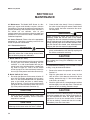
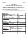
7.1 DIAGNOSTICS AND TROUBLESHOOTING WITH MODEL 54/81/3081 pH/ORP. The Model 54 and 54e
Analyzers and Models 81 and 3081 pH Transmitters automatically search for fault conditions that would cause an
error in the measured pH value, as does the Model 1054A/B pH/ORP Analyzer to a lesser degree. Refer to the
respective manual for a complete description of the analyzer’s fault conditions.
Table 7-1 lists the Analyzer/Transmitters diagnostic messages that indicate a possible sensor problem. A more
complete description of the problem and a suggested remedy corresponding to each message is also listed.
TABLE 7-1 Troubleshooting with Diagnostics
DIAGNOSTIC MESSAGE
54 and 54e
81/3081
“Calibration Warning”
DBMJcsBtF
“Cracked glass failure”
7MBTT!GBJM
“High reference imped”
sFG!GBJM or sFG!WBso
DESCRIPTION OF PROBLEM
REMEDY
1. Aged glass.
2. Sensor not immersed.
1. Perform buffer calibration.
2. Be sure electrode measuring tip is in
process.
Replace Sensor.
Broken or cracked glass.
1. Liquid junction coated.
2. Reference Cell gel depleted.
3. Sensor not immersed.
“Input voltage high”
“Input voltage low”
pH input shorted or sensor.
miswired.
“Old glass warning”
1. Glass electrode worn out.
2. Sensor not immersed.
7MbTT!WBso
“Reference offset err”
(offline only)
Tte!Fss
“Ref voltage high”
“Ref voltage low”
“Sensor line open”
MJoF!GBJM
Reference electrode poisoned.
1. Reference shorted or sensor
miswired.
2. Sensor not immersed.
1. Open wire between sensor and analyzer.
2. Interconnecting cable greater than
1000 ft.
1. Clean sensor; replace if necessary.
2. Replace sensor.
3. Be sure electrode measuring tip is in
process.
Check wiring. Replace sensor if
necessary.
1. Replace sensor.
2. Be sure electrode measuring tip is in
process.
Replace sensor.
Check wiring. Replace sensor if
necessary.
1. Check sensor wiring.
2. Relocate analyzer.
“Sensor miswired”
1. Open wire between sensor and analyzer. 1. Check wiring.
2. Bad preamplifier.
2. Replace preamplifier.
“Temp error high”
“Temp error low”
1. Open or shorted RTD.
2. Temperature out of range.
tFMQ!IJ
tFMQ!MP
36
1. Replace sensor.
2. Check process temperature.
MODEL 396R pH/ORP
SECTION 7.0
DIAGNOSTICS AND TROUBLESHOOTING
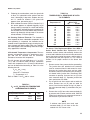
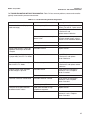
7.2 TROUBLESHOOTING WITHOUT DIAGNOSTICS. Table 7-2 lists common problems, causes and remedies
typically encountered in process measurement.
TABLE 7-2. Troubleshooting without Diagnostics
Problem
Probable Cause
Remedy
Meter reads off scale. (Display
reads overrange).
Defective preamplifier.
Replace preamplifier (for code 02
sensors). For code 01, replace sensor.
T.C. element shorted.
Check T.C. element as instructed
in Section 6.5 and
replace sensor if defective.
Sensor not in process or sample
stream is low.
Make sure sensor is in process with
sufficient sample stream (refer to
Section 2.0 for installation details).
Open glass electrode.
Replace sensor.
Reference element open - no contact.
Replace sensor.
Display reads between 3 and 6 pH
regardless of actual pH of solution
or sample.
Electrode cracked.
Replace sensor.
Meter or display indication swings
or jumps widely in AUTO T.C. Mode.
T.C. element shorted.
Check T.C. element as instructed
in Section 6.5 and replace
sensor if defective.
Span between buffers extremely
short in AUTO T.C. Mode.
T.C. element open.
Check T.C. element as instructed
in Section 6.5 and replace sensor
if defective.
Sluggish or slow meter indication
for real changes in pH level.
Electrode coated.
Clean sensor as instructed in
Sections 6.3 or 6.4. Replace
sensor if cracked.
Electrode defective.
Replace sensor.
Electrode coated or cracked.
Clean Sensor as instructed in
Sections 6.3 or 6.4 Replace
sensor if cracked.
Defective preamplifier.
Replace preamplifier.
Aged glass electrode or high
temperature exposure.
Replace sensor.
Electrode coated .
Clean Sensor as instructed in
Sections 6.3 or 6.4. Replace
sensor if cracked.
Transmitter cannot be standardized.
Transmitter short spans between
two different buffer values.
37
Model 396R pH/ORP
SECTION 8.0
RETURN OF MATERIAL
SECTION 8.0
RETURN OF MATERIAL
8.1 GENERAL.
8.3 NON-WARRANTY REPAIR.
To expedite the repair and return of instruments, please
call 1-949-757-8500 for a R e t u r n M a t e r i a l s
Authorization (RMA) number.
The following is the procedure for returning for repair
instruments that are no longer under warranty:
1.
Call Rosemount Analytical for authorization.
8.2 WARRANTY REPAIR.
2.
Supply the purchase order number, and make
sure to provide the name and telephone number
of the individual to be contacted should additional
information be needed.
3.
Do Steps 3 and 4 of Section 8.2.
The following is the procedure for returning instruments still under warranty:
1.
Call Rosemount Analytical for authorization.
2.
To verify warranty, supply the factory sales order
number or the original purchase order number. In
the case of individual parts or sub-assemblies, the
serial number on the unit must be supplied.
3.
Carefully package the materials and enclose your
“Letter of Transmittal” (see Warranty). If possible,
pack the materials in the same manner as they
were received.
4.
Send the package prepaid to:
Emerson Process Management
Liquid Division
2400 Barranca Parkway
Irvine, CA 92606
Attn: Factory Repair
RMA No. ____________
Mark the package: Returned for Repair
Model No. ____
38
NOTE
Consult the factory for additional information regarding service or repair.
WARRANTY
Seller warrants that the firmware will execute the programming instructions provided by Seller, and that the Goods manufactured
or Services provided by Seller will be free from defects in materials or workmanship under normal use and care until the expiration of the applicable warranty period. Goods are warranted for twelve (12) months from the date of initial installation or eighteen
(18) months from the date of shipment by Seller, whichever period expires first. Consumables, such as glass electrodes,
membranes, liquid junctions, electrolyte, o-rings, catalytic beads, etc., and Services are warranted for a period of 90
days from the date of shipment or provision.
Products purchased by Seller from a third party for resale to Buyer ("Resale Products") shall carry only the warranty extended by
the original manufacturer. Buyer agrees that Seller has no liability for Resale Products beyond making a reasonable commercial
effort to arrange for procurement and shipping of the Resale Products.
If Buyer discovers any warranty defects and notifies Seller thereof in writing during the applicable warranty period, Seller shall, at
its option, promptly correct any errors that are found by Seller in the firmware or Services, or repair or replace F.O.B. point of manufacture that portion of the Goods or firmware found by Seller to be defective, or refund the purchase price of the defective portion of the Goods/Services.
All replacements or repairs necessitated by inadequate maintenance, normal wear and usage, unsuitable power sources, unsuitable environmental conditions, accident, misuse, improper installation, modification, repair, storage or handling, or any other
cause not the fault of Seller are not covered by this limited warranty, and shall be at Buyer's expense. Seller shall not be obligated to pay any costs or charges incurred by Buyer or any other party except as may be agreed upon in writing in advance by
an authorized Seller representative. All costs of dismantling, reinstallation and freight and the time and expenses of Seller's personnel for site travel and diagnosis under this warranty clause shall be borne by Buyer unless accepted in writing by Seller.
Goods repaired and parts replaced during the warranty period shall be in warranty for the remainder of the original warranty period or ninety (90) days, whichever is longer. This limited warranty is the only warranty made by Seller and can be amended only
in a writing signed by an authorized representative of Seller. Except as otherwise expressly provided in the Agreement, THERE
ARE NO REPRESENTATIONS OR WARRANTIES OF ANY KIND, EXPRESS OR IMPLIED, AS TO MERCHANTABILITY, FITNESS FOR PARTICULAR PURPOSE, OR ANY OTHER MATTER WITH RESPECT TO ANY OF THE GOODS OR SERVICES.
RETURN OF MATERIAL
Material returned for repair, whether in or out of warranty, should be shipped prepaid to:
Emerson Process Management
Liquid Division
2400 Barranca Parkway
Irvine, CA 92606
The shipping container should be marked:
Return for Repair
Model _______________________________
The returned material should be accompanied by a letter of transmittal which should include the following information (make a
copy of the "Return of Materials Request" found on the last page of the Manual and provide the following thereon):
1.
2.
3.
4.
5.
Location type of service, and length of time of service of the device.
Description of the faulty operation of the device and the circumstances of the failure.
Name and telephone number of the person to contact if there are questions about the returned material.
Statement as to whether warranty or non-warranty service is requested.
Complete shipping instructions for return of the material.
Adherence to these procedures will expedite handling of the returned material and will prevent unnecessary additional charges
for inspection and testing to determine the problem with the device.
If the material is returned for out-of-warranty repairs, a purchase order for repairs should be enclosed.
The right people,
the right answers,
right now.
ON-LINE ORDERING NOW AVAILABLE ON OUR WEB SITE
http://www.raihome.com
Specifications subject to change without notice.
8
Credit Cards for U.S. Purchases Only.
Emerson Process Management
2400 Barranca Parkway
Irvine, CA 92606 USA
Tel: (949) 757-8500
Fax: (949) 474-7250
http://www.raihome.com
© Rosemount Analytical Inc. 2011