1
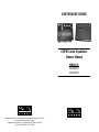
EARTHQUAKE SOUND
EQPXI Series Equalizers
Owners Manual
MODELS:
EQ4000PXi
EQ7000PXi
The Sound That Will Move You.
The Sound That Will Move You.
Earthquake Sound reserves the right to amend details of the specifications without notice.
Copyright © Earthquake Sound Corporation
Earthquake Sound Corporation • 2727 McCone Avenue Hayward CA, 94545
Phone: 510-732-1000 Fax: 510-732-1095
Table Of Contents
Warranty Information / Warranty
Warranty
Wiring Configurations
Mounting Assembly
EQ-4000PXi Panel Overview
EQ-7000PXi Panel Overview
EQ-4000PXi Specifications
EQ-7000PXi Specifications
Input Gain Settings
Care and Maintenance
Warranty Continued
Page • 2
Page • 3
Page • 4
Page • 5
Page • 6
Page • 7
Page • 8
Page • 9
Page • 10
Page • 11
(C) Earthquake will repair or replace - at our option - all defective products/parts subject
to the following provisions:
• Defective products/parts have not been altered or repaired by other than an Earthquake
factory approved technician.
• Products/parts are not subjected to negligence, misuse, improper use, or accident, damaged
by improper line voltage, used with incompatible products, or have its serial number or any part
of it altered, defaced or removed, or have been used in any way that is contrary to Earthquake's
written instructions.
(D) Warranty Limitations:
Regarding Your Warranty:
Thank you for choosing Earthquake Sound’s line of EQPXi equalizers for superior
enhancement of your mobile audio system. With proper installation and responsible listening, your
EQ(s) will give you years of near perfect sound reproduction. We strongly recommend you to have
your new EQ(s) installed by an authorized Earthquake Sound dealer: Installation professionals
employed by your dealer have the correct tools and knowledge to install your product neatly and
successfully. Also, when your new products are installed by an authorized dealer, your product will
include a FIVE YEAR LIMITED WARRANTY.
If you choose to perform your own installation, your warranty will be subject to limitations. Dealer
policies on handling warranty requests may vary from one dealer to the next. Please read the
warranty information in its entirety and use good judgment when making these vital decisions.
Warranty does not cover products that have been modified or abused. Including but not limited
to the following:
• Damages to speaker cabinet and cabinet finish due to misuse, abuse, or use of improper use
of cleaning materials/methods.
• Bent speaker frame, broken speaker connectors, holes in speaker cone, surround & dust cap,
burnt speaker voice coil.
• Fading, deterioration of speaker components & finish due to improper exposure to elements.
• Bent amplifier casing, damaged finish on the casing due to abuse, misuse, or improper use of
cleaning material.
• Burnt tracers on PCB.
• Product/part damaged due to poor packaging or abusive shipping conditions.
• Subsequent damage to other products.
A warranty claim will not be valid if the warranty registration card is not properly filled &
returned to Earthquake with a copy of the sales invoice.
(E) Service Request:
To receive product/s service, contact Earthquake service department at (510) 7321000 and request an RMA number (Return Material Authorization), items shipped without a valid
RMA number will be refused. Make sure you provide us with your complete/correct shipping
address, a valid phone number, and a brief description of the problem you are experiencing with the
product. In most cases, our technicians might be able to resolve the problem over the phone, thus
eliminating the need to ship the product.
Warranty and Guide Lines
Five (5) year limited warranty:
Earthquake warrants the original purchaser that all Factory Sealed New Audio
Products be free from defects in material and workmanship under normal and proper use for a
period of five (5) years from the date of purchase (as shown on the original bill of sale with serial
number affixed/written on it). The five (5) year warranty period is valid only if an authorized
Earthquake dealer properly installs the product and the warranty registration card is properly
filled out and sent to Earthquake Sound Corporation. If a non-authorized party installs the
product a ninety (90) day warranty period will be applied.
(A) Five (5) years limited warranty plan coverage guidelines:
• First year: Earthquake pays for labor, parts, and ground freight (only in US mainland, not
including Alaska and Hawaii).
• Second year: Earthquake pays for labor and parts only, customer must pay freight both ways.
• Third, fourth & fifth year: Earthquake pays labor only. Customer must pay for parts and
freight both ways.
(B) Warning:
Products (sent for repair) that are tested by Earthquake technicians and deemed to
have no problem(s) will not be covered by the five (5) year limited warranty. Customer will be
charged a minimum of one (1) hour of labor (ongoing rates) plus shipping charges back to
customer.
2
www.earthquakesound.com
(F) Shipping Instructions:
Product/s must be packaged in its original protective box(s) to minimize transport
damage. Shipper claims regarding items damaged in transit must be presented to carrier.
Earthquake Sound Corporation reserves the right to refuse product improperly packed. Original bill
of sale must accompany product returned for service. We encourage you to include with the
package a written description of the problem. Ship product to: Earthquake Sound Corp. 2727 Mc
Cone Avenue, Hayward, CA 94545. Ph (510) 732-1000. You are responsible for the cost of shipping
the product to Earthquake Sound Corporation.
(G) Disputes Resolution:
All disputes - between clients and Earthquake Sound Corporation - resulting from
the five (5) years limited warranty policy must be resolved according to the laws & regulations of the
county of Alameda -California.
Alternatively you may register your products online at
http://earthquakesound.com/form_reg.htm
All specifications are subject to change without notice.
3
4
www.earthquakesound.com
All specifications are subject to change without notice.
5
Kompressor K-10
10" Tubed Bass
Unit Usually Placed
In The Trunk
Crossover
Frequency
Bypass
CH2
E
VOLU
M
3/4" - 19.05mm Tapping Screw (2)
MONO
22+
1+
2
1
Gain
2
1
POWER
Born In The USA
REM GND
Power
Mounting Bracket
BAT
Output
Bypass
FRONT
quali
zer
SUB OUT
Mid Woofer
Tweeter
Dash Board
REAR
EQ7000PXi or EQ4000PXi
FUSE
Rca level input
Fron
t of E
Speaker
Level
Input
1-
Stock or after
market head unit
(radio, stereo)
Auxiliary Source
20Hz 5kHz
Filter
Setting
RADIO IN
AUX
SPEAKER
CH1
Protect
Mounting Assembly
Back View
Front View
Wiring Configuration
For Both EQ7000PXi
and EQ4000PXi
Antenna
Tweeter
Mid Woofer
12VDC Ground
REAR
MAIN IN
CD IN
Antenna
12VDC Ground
5/16" - 7.9375mm Machine Screws (4)
VTEK-MC6
2-Way Matched Component System
Usually Located In The Front and or
Rear Doors
- Two 6-1/2" Midrange Drivers
- Two 1" Silk Dome Neo Tweeters
- Two High Precision Crossovers
Back View
Front View
To Head Unit Power/12VDC
To Amp Remote
To Head Unit Ground or Vehicle Chassis
SUB OUT
VTEK-693
3-Way 6 x 9" Speakers
Usually Located In The
Rear Deck
FRONT
6
www.earthquakesound.com
All specifications are subject to change without notice.
7
2
3
2
3
Use Main volume control to adjust the system as one.
2. Main Volume / Fader Action Control: The lower
and wider knob is the volume control and the skinnier
top knob is the Fader control.
The crossover is adjustable from 35Hz to 100Hz.
Depending on the subwoofer frequency response
adjust this knob to the most desired setting.
The subwoofer frequency crossover allows you to
adjust the cross over point for your subwoofer system.
The EQ-4000PXi features separate dual RCA outputs
for the subwoofer channel, sot that the subwoofer(s)
can run on a separate amplifier or separate channels
of a multi-channel amplifier.
1. Subwoofer Level / Subwoofer Crossover Adjust:
Gives you complete control of low musical frequency
ranges. The Sub knob is equal to level control. It
allows you to adjust subwoofer sound levels for a
particular source type: Tape, broadcast, CD..etc.
1
EQ7000PXi Panel Overview
4. 4-Band Rotary Controls: Gives you control of the
higher musical frequency ranges that most head units
cannot accomplish. These controls allow end users to
tailor their music to personal preference and
precision.
3. Fader Action: Use this rotary knob to blend more
action into either the Front or Rear channels of your
system.
2. CD/Main Toggle: Push button to switch between CD
changer or Main (MAIN includes: Radio & Frontal
phono/auxiliary input). If the front mounted auxiliary
input is in use, in other words an iPod or MP3 player
are connected; the EQ-4000PXi/EQ-7000PXi will
automatically default to the front mounted aux input
when the unit is switched to Main from CD.
1. Main Volume Control: Push in once to eject button
then rotate to adjust volume.
1
EQ4000PXi Panel Overview
4
6
5
5. Phono/Auxilliary Input: This unique feature is for
easy iPod and MP3 hook up. Simply plug-n-play.
Once this connection has been made it will over ride
the AUX input plugged into the back of the unit.
4. 7-Band Rotary Controls: Gives you control of the
higher musical frequency ranges that most head units
cannot accomplish. These controls allow end users to
tailor their music to personal preference and
precision. And the each knob has mid point notch to
let the user know when the knob is centered.
3. CD/Main Toggle: Push button to switch between CD
changer or Main (MAIN includes: Radio & Frontal
phono/auxiliary input). If the front mounted auxiliary
input is in use, in other words an iPod or an MP3
player are connected; the EQ-4000PXi/EQ-7000PXi
will automatically default to the front mounted aux
input when the unit is switched to Main from CD.
Use the Fader knob to blend more action into either
the Front or Rear channels of your system.
4
6. Phono / Auxilliary Input: This unique feature is for
easy iPod and MP3 hook up. Simply plug-n-play.
Once this connection has been made it will over ride
the MAIN input plugged into the back of the unit.
The crossover is adjustable from 35Hz to 100Hz.
Depending on the subwoofer frequency response
adjust this knob to the most desired setting.
The subwoofer frequency crossover allows you to
adjust the cross over point for your subwoofer system.
The EQ-4000PXi features separate dual RCA outputs
for the subwoofer channel, sot that the subwoofer(s)
can run on a separate amplifier or separate channels
of a multi-channel amplifier.
5. Subwoofer Level / Frequency Adjust: Gives you
complete control of low musical frequency ranges.
The Sub knob is equal to level control. It allows you to
adjust subwoofer sound levels for a particular source
type: Tape, broadcast, CD..etc.
5
EQ4000PXi Specifications
EQ7000PXi Specifications
Operating Voltage: 10.5---16VDC
Operating Voltage: 10.5---16VDC
Idle: 280 mA
Idle: 170 mA
Recommended fuse size: 1 Ampere
Recommended fuse size: 1 Ampere
Input sources: 2 stereo RCA sources, 1 Phono source
Input sources: 2 stereo RCA sources, 1 Phono source
Input sensitivity: Adjustable from 100mVrms up to 14 Vrms
Input sensitivity: Adjustable from 100mVrms up to 14 Vrms
Input impedance: Variable from 8 kOhm up to 10.2 Kohm
Input impedance: Variable from 3.8 Kohm up to 10.2 Kohm
Output Impedance:
Output Impedance:
Sub channel: 510 Ohm
Sub channel: 510 Ohm
Front & Rear channels: 2.2 Kohm
Front & Rear channels: 2.2 Kohm
Output Level:
Output Level:
Subwoofer channel: 5 Vrms @ 0.1% THD
Front & Rear channels: 4 Vrms @ 0.1% THD
Subwoofer channel: 11 Vrms @ 0.1% THD
Front & Rear channels: 7 Vrms @ 0.1% THD
T H D @ 3 Volts output: 0.05%
T H D @ 3 Volts output: 0.003%
Frequency response: 15 - 34000Hz @ -3dB
Frequency response: 15 - 34000Hz @ -3dB
Subwoofer frequency control range: 35 to 100Hz (@ -3db, 18dB/oct.)
Subwoofer frequency control range: 60 to 160Hz (@ -3db, 18dB/oct.)
Subwoofer upper cut off frequency: 100Hz
Subwoofer upper cut off frequency: 160Hz
Channel separations: 68dB
Channel separations: 68dB
Signal to noise ratio: 92dB
Signal to noise ratio: 96dB
Center frequencies (in Hz): 50, 250, 275, 2200, 16000
Center frequencies (in Hz): 45, 120, 275, 700, 2000, 5000, 14000
Control Range: 30~40dB (12 O'clock is the Bypass position)
Control Range: 18dB (12 O'clock is the Bypass position)
Dimensions(H x W x D): 1" x 7" x 4-1/4" (With Out Face Plate)
Dimensions(H x W x D): 1" x 7" x 4-1/4" (With Out Face Plate)
EQ4000PXi Features
EQ7000PXi Features
* 4-band Graphic Equalizer
* 7-band Graphic Equalizer
* 6-channel RCA Outputs (front/rear/subwoofer)
* 6-channel RCA Outputs (front/rear/subwoofer)
* Adjustable Master Volume Level Control
* Adjustable Master Volume Level Control
* Adjustable Subwoofer Level Control
* Adjustable Subwoofer Level Control
* 3 Input Sources
* 3 Input Sources
* Input Gain (it Sets The Maximum Volume Level Achievable By The Front Controls)
* Input Gain (it Sets The Maximum Volume Level Achievable By The Front Controls)
* Gold Plated RCAs
* Gold Plated RCAs
* Easy Snap On Connector
* Easy Snap On Connector
* Red Led Background Display
* Bypass Position Notches On All 7-bands
* Blue Background LEDs
8
www.earthquakesound.com
All specifications are subject to change without notice.
9
10
www.earthquakesound.com
5V
1.6V
5V
5V
Your Earthquake Stereo 7-Band Graphic Equalizer is an example of superior design and
craftsmanship. The following advisories will help you care for your equalizer so you can
enjoy it for years to come.
Keep the graphic equalizer dry. If it gets wet, wipe it dry immediately.
Liquids contain minerals that can corrode electronic circuits. Additionally
liquids can cause severe electrical shock.
600mV
3V
4V
4.2V
Use and store the graphic equalizer only in normal temperature
environments. Temperature extremes can shorten the life of electronic
devices and warp or melt plastic parts.
MAX
MAX
MAX
MAX
Handle the graphic equalizer gently and carefully. Dropping it can
damage the circuits or cause components to break or become loose.
These kind of actions can cause the units to work poorly or improperly.
200mV
MAX
2V
1V
3 O'clock
9 O'clock
>13V
Keep the graphic equalizer away from dust and dirt, which can cause
premature wear of parts.
12 O'clock
Front & Rear Output
Subwoofer Output
V @ 0.1% THD
Voltage (Sub Gain @ MAX)
Volume Control
Position
Source Voltage
Input Gain's Position
EQ4000PXi
11.2V
7.7V
3V
MAX
1V
MAX
11.2V
7V
7V
MAX
MAX
3.3V
3V
MAX
2 O'clock
11.2V
12V
7V
7V
MAX
MAX
>13V
4V
12 O'clock
10 O'clock
Front & Rear Output
Subwoofer Output
V @ 0.1% THD
Voltage (Sub Gain @ MAX)
Volume Control
Position
Source Voltage
Input Gain's Position
EQ7000PXi
Sample of voltage output with reference to voltage input:
needs to know the output voltage of the source units and set the Input gain accordingly.
high volume. Setting the Input Gain level depends on the sources' maximum signal strength (expressed in Voltage). Installer
Designed to set the maximum upper volume level, the Input Gain is a tool for installer to protect the system from excessive
Input Gain setting:
Care and Maintenance
Earthquake products are capable of generating high sound pressure levels. You
should exercise caution when operating these products. Long term exposures to
high levels of sound pressure will cause permanent damage to your hearing.
Sound pressure levels exceeding 85dB can be dangerous with constant exposure. Set your audio
system to a comfortable loudness level. Earthquake Sound Corporation does not assume liability
for damages resulting from the direct use of Earthquake amplifiers or other Earthquake products ,
and urges users to play their music at moderate listening levels.
CAUTION:
SOUND LEVEL
DURATION IN HOURS
90
92
95
97
100
102
105
110
115
8
6
4
3
2
1 - 1 1/2
1
1/2
1/4 or less
The Chart (on The Side) Shows The
Elements.u.s. Governments Occupational
Safety And Health Administration (osha)
Regulations Which Were In Effect At The
Time Of This Publication For Permissible
Noise Exposure, Per 29cfr1910.95, Table
G-16.
All specifications are subject to change without notice.
11