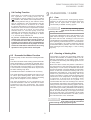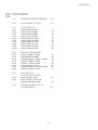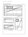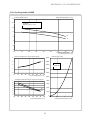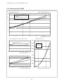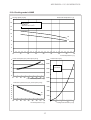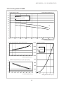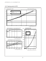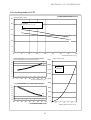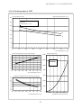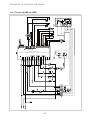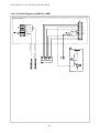
1
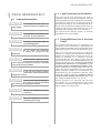
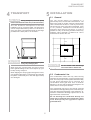
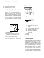
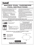
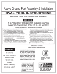
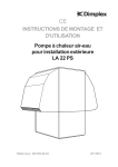
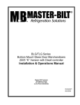
CE
INSTALLATION and OPERATING
INSTRUCTIONS
Air-to-Water Heat Pump
for Outdoor installation
LA 6MR
LA 8MR
LA 10MR
Order No.: 452159.67.07
LA 12TR
LA 16TR
FD 8602
CONTENTS
1
READ IMMEDIATELY
3
1.1
1.2
1.3
Important Information
Legal Provisions and Guidelines
Energy-Efficient Use of the Heat Pump
2
PURPOSE OF HEAT PUMP
2.1
2.2
Field of Application
Principle of Operation
3
SCOPE OF DELIVERY
3.1
3.2
Baseline Unit
Control Box
4
TRANSPORT
5
5
INSTALLATION
5
5.1
5.2
General
Condensate Line
6
MOUNTING
6.1
6.2
6.3
General
Heating-Side Connection
Electrical Connection
7
COMMISSIONING
7.1
7.2
7.3
General
Preparatory Steps
Procedure
8
FUNCTIONAL DESCRIPTION
8.1
8.2
8.3
8.4
8.5
Heat Pump Remote Control Unit
Control Board
Heating Function
Cooling Function
Domestic Hot Water Function
9
CLEANING / CARE
9.1
9.2
9.3
Care
Cleaning of Heating Side
Cleaning of Air Side
10
MALFUNCTIONS / TROUBLESHOOTING
10
11
DECOMMISSIONING
10
11.1
End-of-Life Decommissioning / Disposal
12
APPENDIX
4
4
6
7
8/9
9/10
FF
2
READ IMMEDIATELY
1
READ IMMEDIATELY
1.2 Legal Provisions and Guidelines
1.1 Important Information
This heat pump was designed and built in
compliance with all relevant EU directives, DIN and
VDE regulations (see CE Declaration of Conformity).
CAUTION!
The electrical connection of the heat pump must be
performed according to and conforming with all relevant VDE, EN and IEC standards. Beyond that, all
technical connection requirements of the local
electrical utility company have to be adhered to.
Do not open the unit unless all
electrical circuits have been disconnected from the
power supply.
CAUTION!
On connecting the heating system, all relevant
regulations have to be heeded.
CAUTION!
1.3 Energy-Efficient Use of the Heat
Pump
During transport, the heat pump must
not be tilted more than 45° (in either direction).
Heat pump and transport pallet are
only connected by the packaging film.
By purchasing this heat pump you contribute to the
protection of the environment. A prerequisite for
energy-efficient operation is the proper design of the
heat source system and the heat utilization system.
CAUTION!
The air intake and discharge
openings must neither be constricted nor
obstructed.
One of the most important factors of heat pump
efficiency is keeping the temperature difference
between the heating water and the heat source as
small as possible. It is therefore strongly
recommended that the design of both the heat
source system and the heat distribution system be
carried out with great care. A 1 Kelvin (1°C) higher
temperature difference corresponds to an
increase in power consumption of approx. 2.5%.
When designing the heating system care must be
taken that special applications such as domestic
water heating are taken into consideration and
dimensioned for low temperature operation. Heat
pumps are optimally suited for underfloor heating
(surface/radiant heating) applications due to the
low supply temperatures (30 °C to 40 °C).
CAUTION!
Clockwise phase sequence (in the
case of multiphase units) must be observed: Damage
to the compressor may be incurred if it is operated
in the wrong sense of rotation.
CAUTION!
Do not use any cleaning agents
containing sand, soda, acid or chloride as these may
damage the surface.
CAUTION!
During operation it is essential that the heat
exchangers are not contaminated as this would
increase the temperature difference resulting in a
lower coefficient of performance.
To prevent consequential damage it
is imperative that the water circuits be neutralized
after cleaning using appropriate agents.
CAUTION!
The unit is not suitable for operation
with a frequency converter.
CAUTION!
Work on the refrigeration circuit may
be performed by qualified persons only.
3
PURPOSE OF HEAT PUMP
SCOPE OF DELIVERY
2
3
PURPOSE OF HEAT
PUMP
2.1 Field of Application
SCOPE OF DELIVERY
3.1 Baseline Unit
The heat pump is deliverd as a compact unit
containing the components listed below.
The air-to-water heat pump is intended for use in
existing or newly built heating systems.
The refrigerant used is R407C.
The heat pump is designed for the cooling or heating
of water for heating purposes and the supply of
domestic hot water!
1
2
3
The heat pump is suitable for mono-energetic and
bivalent operation.
During heating mode, a heating water return
temperature of more than 18 °C must be maintained
in order to assure proper defrosting of the
evaporator.
The heat pump is generally not designed for
satisfying any increased heat demand during the
drying phase of new buildings. The additional heat
demand must therefore be met by special appliances
to be supplied on site. For the structural drying of
new buildings during autumn and winter, its is
recommended that an additional electric heating
element (available as an accessory) be installed.
4
CAUTION!
The unit is not suited for operation
with a frequency converter.
2.2 Principle of Operation
Ambient air is drawn in by the fan and passed over a
finned heat exchanger, which extracts heat from the
air in the heating mode or gives off heat to the air in
the cooling mode. This energy difference is
transferred to the working fluid (refrigerant) in the
heat exchanger.
9
With the aid of an electrically driven compressor, the
absorbed heat is "pumped" to a higher temperature
level through pressure increase and - depending
on the particular application (cooling or heating) - is
given off to the heating water or the waste air via the
heat exchanger.
1)
2)
3)
4)
5)
During heating mode, electrical energy is used to
raise the heat of the environment to a higher
temperature level. Due to the fact that the energy
extracted from the air is transferred to the heating
water, this type of appliance is referred to as air-towater heat pump.
8
7
Evaporator
Control box
Fan
Pressostats
Expansion vessel
6
5
6) Receiver/
filter drier
7) Circulat. pump
8) Electric heater
9) Compressor
3.2 Control Box
The control box is integrated in the heat pump. It is
accessible after removal of the cover panel (the
fastening screw holes of the cover panels are
capped).
The air-to-water heat pump consists of the following
main components: evaporator, fan and expansion
valve as well as the low-noise compressor, a
condenser and the electric control unit.
The control box houses the mains terminals, the
power contactors, the soft start unit as well as the
terminals for the remote control.
In the case of low ambient temperatures in the
heating mode, moisture contained in the air may
accumulate on the evaporator in the form of frost
thus impairing the heat transfer. The evaporator is
automatically defrosted by the heat pump, if required.
Vapour pluming may occur at the air outlet depending
on the weather conditions.
The control of the heat pump is effected via the
remote control included in the scope of delivery (see
also section 8.).
4
TRANSPORT
INSTALLATION
4
5
TRANSPORT
CAUTION!
INSTALLATION
5.1 General
The unit should always be installed on a
permanently level, smooth and horizontal floor. The
base frame (with its contact surfaces) should make
close contact with the floor in order to prevent any
structure-borne noise from being transmitted. If this
is not possible, additional sound-absorbing
measures might become necessary. It must be
possible to carry out servicing activities without any
problems. This is assured if a clearance of 1.2m is
maintained all around the unit.
During transport, the heat pump
must not be tilted more than 45° (in either direction).
The unit should be transported to the final
installation site on a wooden pallet. The heat pump
can be transported either by means of a lift truck or
using 3/4" pipes to be passed through the openings
provided in the base plate or in the frame.
1,2 m
1,2 m
1,2 m
1,2 m
CAUTION!
The heat pump and transport pallet
are only connected by the packaging film.
CAUTION!
The air intake and discharge
openings must not be restricted nor obstructed.
When using 3/4" carrying pipes, be sure to secure
them against shifting so as to avoid injuries (to your
hands) during transport!
When slipping the carrying pipes through the frame,
care must be taken that no components (in particular
the plastic condensate pan or the drain pipe socket)
are damaged.
5.2 Condensate Line
The condensation water that may collect during
operation must be drained in a place protected from
frost. The heat pump must be positioned horizontally
so that proper discharge can be ensured. The
condensation water pipe must have a minimum
diameter of 50 mm and should be discharged to the
sewer drain in a frost-proof location.
The condensate pipe has to be placed centered
unterneath the drain pipe fitting of the condensate pan
(see also dimensioned drawing in the Appendix). Alternative condensate discharge options have to be
agreed with the manufacturer.
Do not discharge the condensate directly into
septic pits or cesspools as the evaporator is likely
to be destroyed by the aggressive vapours
generated there.
5
MOUNTING
6
6.3 Electrical Connection
MOUNTING
6.1 General
The power connection of the heat pump is effected
via a standard 3-core (for 1-phase units) or a 5-core
(for 3-phase units) cable.
The following connections need to be established
on the heat pump:
In the case of the 1-phase units, an additional 3-core
cable must be installed for the electric back-up heater.
-
The cable(s) has (have) to be supplied by the client;
the cross-sectional area is to be selected in
accordance with the power consumption of the heat
pump (see Equipment Data in the appendix) as well
as all relevant VDE (EN) and VNB regulations.
supply/return lines of the heating system
condensate drain
control lead to the remote control
power supply
The power supply of the heat pump must be equipped
with an all-pole disconnecting device with a contact
gap of at least 3 mm (e.g. utility company shut-off
contactor, power contactor) as well as a 3-pole circuit
breaker, with simultaneous tripping of all external
conductors (tripping current as stated in the Equipment Data).
6.2 Heating-Side Connection
The connections on the heating side of the heat
pump are provided with 1"external thread (flat
sealing). When making the connections to the heat
pump, use a wrench to counterhold at the transitions.
Before completing the heat pump connections on
the heating water side, the heating installation must
be flushed in order to remove any impurities that
may be present, as well as any residues of sealing
material, and the like. Any accumulation of deposits
in the condenser may result in a total failure of the
heat pump. On systems equipped with heating water
flow shut-off devices such as radiator or thermostat
valves, an overflow valve, to be provided by the
customer, needs to be installed at the outlet of the
heat pump in a heating system bypass. This assures
a minimum heating water flow through the heat
pump and thus prevents any malfunctions from
occurring.
- optionally, an additional three-core cable is
required for the domestic hot water supply.
When connecting multiphase units the clockwise
phase sequence of the motor electrical supply must
be assured.
Phase sequence: L1, L2, L3.
CAUTION!
Clockwise phase sequence (in the
case of multiphase units) must be ensured: Operating
the compressor in the wrong sense of rotation, may
result in damage to the compressor. An incorrect
phase sequence causes the fan to operate in the
wrong sense of rotation leading to a significant
reduction in performance.
Once the installation on the heating side has been
completed, the heating system must be filled, deaerated and pressure-tested..
The control voltage for the remote control is provided
by the power supply of the unit.
The connecting lead (control lead) from the remote
control to the heat pump (not included in the scope of
delivery) must be suitable for 230 V mains power
supply. The lead must have (at least) 6 cores and the
cross-section of the single cores must be at least 0.5
mm2.
The power supply of the heat pump must be as
specified in the Technical Data of the applicance, i.e.
230 V AC 50 Hz or 3-L/N/PE 400 V.
Heating water minimum flow rate
The heating water minimum flow rate through the heat
pump must be assured in all operating states of the
heating system. This can be accomplished, for example,
by installing a differential pressure-free manifold or an
overflow valve. The procedure for setting an overflow
valve is described in the Chapter Commissioning.
Frost Protection
On heat pumps installed in a location prone to frost,
a manual drain valve (see "Hydraulic Block Diagrams"
in the Appendix) should be provided. Properly installed
appliances feature an internal frost protection feature.
If the heat pump is taken out of service or in the event
of a power failure, the system must be drained. In
heat pump installations where a power failure cannot
be readily detected (e.g. holiday houses), the heating
circuit must contain a suitable antifreeze product.
The connection inside the heat pump is to be effected
using the terminal strips in the control box. For
detailed information refer to the Wiring Diagrams in
the Appendix.
6
COMMISSIONING
7
COMMISSIONING
Heat source temperature
from
to
7.1 General
To ensure proper commissioning it should be
carried out by an after-sales service authorized by
the manufacturer. Only then can an extended
warranty period of 3 years in total be granted (cf.
Warranty service).
7.2 Preparatory Steps
Prior to commissioning, the following items need to
be checked:
- In the heating circuit all valves that could impair
the proper heating water flow must be open.
path
must
-20 °C
-15 °C
-14 °C
-10 °C
4K
5K
-9 °C
-5 °C
6K
-4 °C
0 °C
7K
1 °C
5 °C
8K
6 °C
10 °C
9K
11 °C
15 °C
10 K
16 °C
20 °C
11 K
21 °C
25 °C
12 K
26 °C
30 °C
13 K
31 °C
35 °C
14 K
The following procedure must be observed so that
the commissioning activities can be carried out
without any problems:
- All connections of the heat pump must have been
made as described in Chapter 6.
- The air intake/discharge
unobstructed.
max. difference between
heating water supply and
return temperature
be
- The sense of rotation of the fan must correspond
to the direction of the arrow.
a)
Close all heating circuits.
b)
Open the overflow valve all the way.
c)
Wait until the buffer tank has reached a
temperature of approx. 25 °C.
d)
Subsequently, slowly reopen the valves of the
heating circuits, one after the other, in such a
way that the heating water flow rate is
continually increased by slightly opening the
related heating circuit. When so doing, the
heating water temperature in the buffer tank
must not fall below 20 °C so that the heat pump
can be defrosted at any time.
e)
Once all heating circuit are fully open and a
heating water temperature of approx. 20 °C is
maintained in the buffer tank, the minimum flow
rate must be set on the overflow valve and the
heating circulating pump.
- An operating mode must have been set on the
remote control.
- Proper condensate drainage must be ensured.
7.3 Procedure
The start-up of the heat pump is effected via the
remote control.
Where an overflow valve is fitted to assure the minimum
heating water flow rate, the valve must be set in
accordance with the specific requirements of the heating
installation. An incorrect setting may result in various
error symptoms and an increased electric power
consumption. To correctly set the overflow valve, the
following procedure is recommended for the "heating
mode":
Close all of the heating circuits that may also be closed
during operation (depending on the type of heat pump
usage) so that the least favourable operating state with respect to the water flow rate - is achieved.
Typically these are the heating circuits of the rooms
on the building's south and west sides. At least one
heating circuit must remain open (e.g. bathroom).
The overflow valve is to be opened to such an extent
that based on the current heat source temperature
the maximum temperature spread between heating
supply and return flow temperature is obtained, as
indicated in the table that follows. The temperature
spread should be measured as closely to the heat
pump as possible. In mono-energetic systems, the
electric heating element is to be deactivated.
7
FUNCTIONAL DESCRIPTION
8
8.2 Control Board
FUNCTIONAL
DESCRIPTION
8.1 Heat Pump Remote Control Unit
The heat pump can be switched on and off by means
of the remote control positioned inside the building.
Switching off in this case means switching to a
"standby" function, i.e. as long as the heat pump is
supplied with mains power, the frost protection
function of the heat pump remains active. If the water
temperature is too low, first the heating circulating
pump, and if this is not enough, also the compressor
must be put in operation. The remote control allows
you to set the heating or cooling operating mode
(the switchover delay from the heating to the cooling
mode, or vice-versa, is 10 min.) as well as the
temperature level of the heating water.
1
2
6 5 4 3 2 1
12
11
7
3
1)
2)
3)
4)
5)
6)
4
7)
8)
1) Switch On/Standby
9)
10)
11)
12)
2) LED (green) is illuminated regardless of the
switch position (indicates operational readiness of heat pump)
3) Switch "Heating" (left side depressed)
Switch "Cooling" (right side depressed)
4) Dial for selecting heating water setpoint
temperature
8
9
10
on
on
off
on
= compressor is operating
= fan is operating
= reversing valve set to "Heating"
= reversing valve set to "Cooling" or
"Defrost"
on = heating circulating pump is operating
off = output backup heater off
on = call for frost protection, HP is heating
off = call for frost protection off
on = low pressure pressostat okay
off = defrost process in progress or
"Heating mode"
on = defrost process is terminated or
"Cooling mode"
not used
not used
flashing during operation
flashing in the event of a malfunction
8.3 Heating Function
Set switch (1) to position On (I) to put heat pump
into operation. The heating mode can be preselected
by placing switch (3) to the Heating ( ) position.
The desired return temperature can be set using
selector dial (4), the relevant call for heat is
controlled by the potentiometer and lies within a
range of min. 10 °C and max. 55 °C. If the preset
temperature is reached, the heat pump switches off.
Once the return temperature drops below the preset
temperature by 4 Kelvin, the heat pump switches
back on. In the event that the preset return
temperature cannot be reached, the output for the
back-up heater cuts in after approx. 1 hour. The heat
pump cannot be restarted until a minimum time delay
of 5 minutes has elapsed. At a supply temperature
of approx. 60 °C or if the air temperature is too low,
the heat pump switches off.
8
FUNCTIONAL DESCRIPTION
CLEANING / CARE
8.4 Cooling Function
9
Place switch (1) in position On (I) to put heat pump
into operation. The cooling mode can be
preselected by placing switch (2) to the Cooling
( ) position. The desired return temperature can
be set using selector dial (4), the relevant call for
heat is controlled by the potentiometer and lies
within a range of min. 12 °C and max. 25 °C. When
the preset temperature is reached, the heat pump
switches off. Once the return temperature exceeds
the preset value by 4 Kelvin, the heat pump
switches back on. The heat pump cannot be
restarted until a minimum time delay of 5 minutes
has elapsed. At a supply temperature of below
7 °C, the heat pump switches off.
CLEANING / CARE
9.1 Care
To protect the paint finish, avoid placing objects
against or on the unit. The external parts of the heat
pump can be wiped with a damp cloth and
commercially available cleaning agents.
CAUTION!
Do not use any cleaning agents
containing sand, soda, acid or chloride as these may
damage the surface.
To prevent malfunctions due to dirt deposits in the
plate heat exchanger of the heat pump, care must
be taken that the heat exchanger cannot become
contaminated in the heating installation. In the event
that operating malfunctions due to contamination
occur nevertheless, the system should be cleaned
as described below. (Caution: The fins of the finned
heat exchanger have sharp edges -> risk of cutting
injuries!)
To prevent condensate from forming on the
system in the case of surface cooling systems, it
is recommended that dew point monitors be
installed at critical places of the cold distribution
system and connected in lieu of jumper A1. In the
event that condensation should form, the cooling
operation of the system will be interrupted.
9.2 Cleaning of Heating Side
8.5 Domestic Hot Water Function
The ingress of oxygen into the heating water may
result in the formation of oxidation products. An additional contamination of the heating water caused
by residues of lubricating and sealing agents occurs
in many cases.
This heat pump can also be used for heating domestic
water.
The call for domestic water heating (and the domestic
water temperature) is controlled by terminal "X2-7"
by means of a thermostat to be provided by the client.
This thermostat connects phase (L) to terminal "X27" and controls a reversing valve which is part of the
hot water switch group "N13".
Both of the above causes may lead to a reduction in
the performance of the plate heat exchanger of the
heat pumps. In such cases, the installer must clean
the heat exchanger concerned. Based on information
known to date we recommend cleaning with a 5%
phosphoric acid solution or, in the case that cleaning
needs to be performed more frequently, with a 5%
formic acid solution. In both cases the cleaning fluid
should be at room temperature. Thorough flushing
is necessary to ensure that all cleaning agent
residues are removed from the system. It is
recommended that the heat exchanger be cleaned
in the direction opposite to the normal flow direction.
Owing to their acid content, flushing agents must be
used with caution. To prevent acidic flushing agents
from entering the heating installation when cleaning
the condenser, we recommend that the flushing
device be mounted directly to the supply and return
line of the heat pump. The regulations of the trade
associations must be adhered to. If in doubt, contact
the manufacturers of the chemicals!
A suitable thermostat is available as an accessory.
The call for domestic water heating may also occur if
no call for space heating exists. On a call for heat,
the control unit switches off the heating circulating
pump and the setpoint is set to maximum.
The water temperature is now controlled by the
external thermostat. After the domestic hot water
preparation has been terminated, the system
returns to the same function that was active before
the call.
CAUTION!
To prevent consequential damage it
is imperative that the water circuit be neutralized
after cleaning using appropriate agents.
9
CLEANING / CARE
MALFUNCTIONS / TROUBLESHOOTING
DECOMMISSIONING
Caution - Heating Contractors
The preset temperature level cannot be reached!
Please check whether
Depending on the water quality and quantity, in
particular in the case of mixed installations and
plastic pipes, mineral deposits (rust sludge, lime)
may form impairing the proper functioning of the
heating installation. A cause of this is the water
hardness as well as oxygen dissolved in the filling
water as well as additional oxygen from the air which
may penetrate via valves, fittings and plastic pipes
(oxygen diffusion). As a preventive measure it is
recommended that a physical water conditioner such
as ELYSATOR be used.
- the permissible operating conditions of the heat
pump are complied with (air temperatures too high
or too low).
- the air inlet or outlet areas are neither covered,
obstructed nor severely contaminated.
- valves or stop-cocks in the water lines (heating
lines) are closed.
- the water temperature in the buffer tank is
sufficiently high.
If you cannot eliminate the malfunction yourself,
please contact your customer service in charge (see
Warranty Certificate).
9.3 Cleaning of Air Side
Finned heat exchangers, fan and condensate drain
should be cleaned of debris (leaves, branches, etc.)
prior to the start of the heating season. Contamination
of this nature can be removed manually using
compressed air or by washing off with clear water.
CAUTION!
Work on the heat pump may be done
only by an authorized and qualified customer service.
The appliance cover and the air intake grille may have
to be removed for this purpose.
CAUTION!
Prior to opening the unit it must be
ensured that all electrical circuits are disconnected
from the power supply.
11
When cleaning do not use any sharp or hard objects
so as to prevent any damage to the evaporator and
the condensate pan.
Extreme weather conditions (e.g. heavy snow) may
in some cases result in ice build-up on the inlet and
outlet grilles. To assure a minimum air flow rate, clear
the inlet and discharge areas of snow and ice, if
needed.
10
MALFUNCTIONS /
TROUBLESHOOTING
This heat pump is a quality product and is designed
for troublefree and maintenance-free operation. In
the event that a malfunction occurs nevertheless,
you will be able to correct the problem easily yourself
in the majority of cases.
Heat pump does not run!
Please check that:
- there is no problem with the power supply (blown
fuse, power failure).
- the power switch on the remote control is switched
on and the correct operating mode is selected, as
well as that the correct setpoint temperature is set.
10
DECOMMISSIONING
11.1 End-of-Life Decommissioning /
Disposal
Before removing the heat pump, disconnect the
appliance from the power supply and close all valves.
Environment-relevant requirements regarding the
recovery, recycling and disposal of service fuels and
components in accordance with all relevant
standards must be adhered to. In this context,
particular attention must be paid to the proper
disposal of refrigerants and refrigeration oils.
APPENDIX
12
APPENDIX
12.1
DIMENSIONED DRAWING
12
12.2
EQUIPMENT DATA
13
12.3
SCHEMATICS
12.3.1
12.3.2
12.3.3
12.3.4
12.3.5
12.3.6
12.3.7
12.3.8
12.3.9
12.3.10
Heating mode LA 6MR
Cooling mode LA 6MR
Heating mode LA 8MR
Cooling mode LA 8MR
Heating mode LA 10MR
Cooling mode LA 10MR
Heating mode LA 12TR
Cooling mode LA 12TR
Heating mode LA 16TR
Cooling mode LA 16TR
12.4
WIRING DIAGRAMS
12.4.1
12.4.2
12.4.3
12.4.4
12.4.5
12.4.6
12.4.7
12.4.8
Control LA 6MR-LA 10MR
Load LA 6MR-LA 10MR
Terminal Diagram LA 6MR-LA 10MR
Legend LA 6MR-LA 10MR
Control LA 12TR-LA 16TR
Load LA 12TR-LA 16TR
Terminal Diagram LA 12TR-LA 16TR
Legend LA 12TR-LA 16TR
12.5
HYDRAULIC
BLOCK DIAGRAMS
12.5.1
12.5.2
Mono-energetic system
Mono-energetic system and
domestic hot water function
12.6
14
15
16
17
18
19
20
21
22
23
24
25
26
27
28
29
30
31
32
33
EC DECLARATION OF
CONFORMITY
34
11
12
Electr.
connection box
(inspection side)
35 (circumferential)
Air discharge end
Condensate drain
Direction of air flow
( Base frame )
Condensate tube
(plastic)
Appliance contact surfaces
(stainless steel)
Condensate drain
Feed-through
Electric lines
Heating water
Return
G 1” external thread
Heating water
Supply
G 1” external thread
to sewer
Soil
Condensate pan
APPENDIX: 12.1 DIMENSIONED DRAWING
Dimensioned Drawing
APPENDIX: 12.2 EQUIPMENT DATA
Equipment Data
EQUIPMENT DATA for air-to-water heat pumps for heating
1
TYPE AND COMMERCIAL DESCRIPTION
LA06MRN
LA08MRN
LA10MRN
LA12TRN
LA16TRN
2
MODEL
2.1
Type
reversible
reversible
reversible
reversible
reversible
2.2
Enclosure type acc. to EN 60 529 for compact unit and/or heating element
IP 24
IP 24
IP 24
IP 24
IP 24
2.3
Installation site
outdoors
outdoors
outdoors
outdoors
outdoors
3
PERFORMANCE DATA
3.1
Operating temperature limits:
Heating water supply / return
°C / °C
max.60/min.18
max.60/min.18
max.60/min.18
max.60/min.18
max.60/min.18
Cooling, flow
°C
+7 to +20
+7 to +20
+7 to +20
+7 to +20
+7 to +20
Air (heating)
°C
-20 to +35
-20 to +35
-20 to +35
-20 to +35
-20 to +35
Air (cooling)
°C
+15 to +45
+15 to +45
+15 to +45
+15 to +45
+15 to +40
3.2
Heating capacity / coeff. of perform. at A7 / W35 1)
kW / ---
6.1 / 3.3
7.4 / 3.3
8.5 / 3.4
11.9 / 3.3
15.3 / 3.3
3.3
Cooling capacity / coeff. of perform. at A35 / W18
at A7 / W45 1)
at A35 / W7
kW / ---
6.1 / 2.7
7.3 / 2.7
8.4 / 2.8
11.6 / 2.7
14.9 / 2.8
kW / ---
7.9 / 3.2
9.4 / 3.3
11.1 / 3.3
15.8 / 3.3
18.5 / 3.3
kW / ---
6.4 / 2.7
7.7 / 2.9
9.0 / 2.9
13.6 / 3.0
16.1 / 3.0
3.4
Sound power level
dB(A)
70
71
71
72
72
3.5
Sound pressure level at 10 m distance (discharge side)
dB(A)
45
46
46
47
47
3.6
Heating water flow rate
m³/h
1.1
1.3
1.5
1.7
1.9
3.7
Free pressure, heating circulating pump (max. stage)
Pa
34800
35600
33800
32700
58900
3.8
Refrigerant; total charge weight
type / kg
R407C / 1.5
R407C / 2.3
R407C / 2.3
R407C / 3.4
R407C / 3.7
3.9
Rating electric heating element (back-up heater) max.
kW
6
6
6
6
6
4
DIMENSIONS; CONNECTIONS AND WEIGHT
4.1
Equipment dimensions
H x W x L cm
86 x 127 x 67
86 x 127 x 67
86 x 127 x 67
86 x 127 x 67
86 x 127 x 67
4.2
Equipment connections for heating
inch
G 1'' external
G 1'' external
G 1'' external
G 1'' external
G 1'' external
4.3
Weight of transport unit(s) incl. packaging
kg
159
165
170
185
196
V/A
230 / 20
230 / 20
230 / 25
400 / 20
400 / 25
4)
4)
4)
5
ELECTRICAL CONNECTION
5.1
Nominal voltage; fusing
5.2
Fuse protection, electric heating element (only 230V units)
A
30
30
30
-
-
5.3
Nominal power consumption 1)
kW
1.9
2.3
2.5
3.6
4.6
5.4
Starting current with soft starter
A
26
32
38
26
27
5.5
Nominal current A2 W35 / cos ϕ
A / ---
6
COMPLIES WITH EUROPEAN SAFETY REGULATIONS
7
OTHER DESIGN CHARACTERISTICS
7.1
Defrosting
automatic
automatic
automatic
automatic
automatic
Defrost type
cycle reversal
cycle reversal
cycle reversal
cycle reversal
cycle reversal
Defrost pan available
yes (heated)
yes (heated)
yes (heated)
yes (heated)
yes (heated)
7.2
Heating water inside unit protected against freezing
yes 2)
yes 2)
yes 2)
yes 2)
yes 2)
7.3
Performance settings
1
1
1
1
1
1)
These data characterize the size and performance of the system. For economic and energetic
considerations, additional factors such as defrosting behaviour, bivalence point and control need to be taken
into account. Abbreviations have the following meaning: e.g. A7 / W35: outside temperature 7 °C and
heating water supply temperature 35 °C.
2)
The heating circulating pump and the controller of the heat pump must be on standby at all times.
3)
See EC Declaration of Conformity
4)
For the electr. connection of the electric heating element, a separate load line with its own fuse protection is required.
A2 W35
Subject to change without notice
10.3
12.5
13.6
6.5
8.3
3)
3)
3)
3)
3)
Issued: 02.03.2006
13
APPENDIX: 12.3 SCHEMATICS
12.3.1 Heating mode LA 6MR
11
Water outlet temperature in [°C]
Wasseraustrittstemperatur
in [°C]
Heating capacity
in [kW]
Heizleistung
in [kW]
10
35
Bedingungen:
Conditions:
Heating water flow rate1,1
1.1 m³/h
m3/h
Heizwasserdurchsatz
9
50
8
7
6
5
4
40
3
2
1
0
-20
-10
0
10
20
Power consumption (incl.
input to pump)
Leistungsaufnahme
(incl.power
Pumpenleistungsanteil)
3
Pressure lossinin[Pa]
[Pa]
Druckverlust
20000
50
40
2
30
40
Lufteintrittstemperatur
[°C]
Air inlet temperature in [°C]
18000
35
16000
Condenser
Verflüssiger
1
14000
0
12000
-20
6
-10
0
10
20
30
40
Lufteintrittstemperatur
Air inlet temperature in
in [°C]
10000
Coefficient
of performance
(incl. power input to pump)
Leistungszahl
(incl. Pumpenleistungsanteil)
8000
35
5
6000
50
4
3
4000
2
40
1
2000
0
-20
-10
0
10
20
30
0
40
0
Air inlet temperature in [°C]
Lufteintrittstemperatur
14
0,5
1
1,5
0,5
1,5
Heizwasserdurchsatz in [m³/h]
Heating water flow rate in [m3/h]
APPENDIX: 12.3 SCHEMATICS
12.3.2 Cooling mode LA 6MR
14
Wasseraustrittstemperatur
[°C]
Water outlet temperature in in
[°C]
Cooling capacity
in [kW]
Kühlleistung
in [kW]
12
Bedingungen:
Conditions:
Water flow rate 1.11,1
m3/h
Wasserdurchsatz
m³/h
10
8
18
6
8
4
2
0
10
4
15
20
25
30
Power consumption (incl.
input to pump)
Leistungsaufnahme
(incl.power
Pumpenleistungsanteil)
35
40
45
50
Lufteintrittstemperatur
[°C]
Air inlet temperature in [°C]
Pressure
lossin
in [Pa]
[Pa]
Druckverlust
20000
18
3
18000
8
2
16000
1
14000
0
12000
10
7
6
5
4
3
2
1
0
Verflüssiger
Condenser
15
20
25
30
35
40
45
50
Lufteintrittstemperatur
Air inlet temperature in
in [°C]
10000
Leistungszahl
(incl.(incl.
Pumpenleistungsanteil)
Coefficient
of performance
power input to pump)
8000
6000
4000
18
8
10
15
20
25
30
35
40
45
2000
50
Lufteintrittstemperatur
[°C]
Air inlet temperature in [°C]
15
0
00
0,5
1
1,5
0,5
1,5
Heizwasserdurchsatz in [m³/h]
Heating water flow rate in [m3/h]
APPENDIX: 12.3 SCHEMATICS
12.3.3 Heating mode LA 8MR
13
Water outlet temperature in [°C]
Wasseraustrittstemperatur
in [°C]
Heating capacity
in [kW]
Heizleistung
in [kW]
12
35
11
Bedingungen:
Conditions:
Heating water flow rate1,3
1.3m³/h
m3/h
Heizwasserdurchsatz
10
50
9
8
7
6
5
40
4
3
2
1
0
-20
-10
0
10
Power consumption (incl.
input to pump)
Leistungsaufnahme
(incl.power
Pumpenleistungsanteil)
4
3
16000
35
2
30
40
Air inlet temperature in [°C]
Lufteintrittstemperatur
[°C]
Pressure
lossinin[Pa]
[Pa]
Druckverlust
18000
50
40
20
Condenser
Verflüssiger
14000
1
12000
0
-20
6
-10
0
10
20
30
40 10000
Air inlet temperature in [°C]
[°C]
Lufteintrittstemperatur
Leistungszahl
(incl. Pumpenleistungsanteil)
Coefficient
of performance
(incl. power input to pump)
35
5
4
50
3
8000
6000
4000
2
2000
40
1
0
-20
-10
0
10
20
30
0
40
00
Air inlet temperature in [°C]
Lufteintrittstemperatur
[°C]
16
0,5
11
1,5
0,5
1,5
22
Heizwasserdurchsatz in [m³/h]
Heating water flow rate in [m3/h]
APPENDIX: 12.3 SCHEMATICS
12.3.4 Cooling mode LA 8MR
18
Wasseraustrittstemperatur
in [°C]
Water outlet temperature in [°C]
Cooling capacity
in [kW]
Kühlleistung
in [kW]
16
Bedingungen:
Conditions:
Water flow rate 1.3 1,3
m3/hm³/h
Wasserdurchsatz
14
12
10
18
8
8
6
4
2
0
10
4
15
20
25
30
Power
consumption (incl.
power
input to pump)
Leistungsaufnahme
(incl.
Pumpenleistungsanteil)
35
18000
40
45
50
Lufteintrittstemperatur
Air inlet temperatureinin[°C]
[°C]
Druckverlust
in [Pa]
Pressure
loss in [Pa]
18
3
8
16000
2
Verflüssiger
Condenser
14000
1
12000
0
10
7
6
5
4
3
2
1
0
15
20
25
30
35
40
45
50 10000
Air inlet temperature
[°C]
Lufteintrittstemperatur
inin[°C]
8000
Coefficient
of performance
(incl.
power input to pump)
Leistungszahl
(incl.
Pumpenleistungsanteil)
6000
4000
18
8
10
15
20
25
30
35
40
45
2000
50
Air inlet temperature in
in [°C]
[°C]
Lufteintrittstemperatur
17
0
0
0,5
1
1,5
2
1,5
Heizwasserdurchsatz in [m³/h]
3
Heating water flow rate in [m /h]
APPENDIX: 12.3 SCHEMATICS
12.3.5 Heating mode LA 10MR
16
Water outlet temperature in [°C]
Wasseraustrittstemperatur
in [°C]
Heating capacity
in [kW]
Heizleistung
in [kW]
35
14
Bedingungen:
Conditions:
Heating water flow rate1,5
1.5m³/h
m3/h
Heizwasserdurchsatz
50
12
10
8
6
40
4
2
0
-20
-10
0
10
Power consumption (incl.
input to pump)
Leistungsaufnahme
(incl.power
Pumpenleistungsanteil)
4
40
30
40
Air inlet temperature in [°C]
Lufteintrittstemperatur
[°C]
Pressure lossinin[Pa]
[Pa]
Druckverlust
18000
50
3
20
16000
35
2
Condenser
Verflüssiger
14000
1
12000
0
-20
7
6
5
4
3
2
1
0
-10
0
10
20
30
40 10000
Air inlet temperature in
in [°C]
Lufteintrittstemperatur
Leistungszahl
(incl. Pumpenleistungsanteil)
Coefficient
of performance
(incl. power input to pump)
35
8000
6000
50
4000
2000
40
-20
-10
0
10
20
30
0
40
0
Air inlet temperature in [°C]
Lufteintrittstemperatur
18
0,5
0,5
1
1,5
2
2,5
Heizwasserdurchsatz in [m³/h]
Heating water flow rate in [m3/h]
APPENDIX: 12.3 SCHEMATICS
12.3.6 Cooling mode LA 10MR
22
Water outlet temperature in [°C]
Wasseraustrittstemperatur
in [°C]
Cooling capacity
[kW]
Kühlleistung
in in
[kW]
20
Bedingungen:
Conditions:
3
Water flow rate 1.5 m
/h m³/h
Wasserdurchsatz
1,5
18
16
14
12
10
18
8
8
6
4
2
0
10
5
15
20
25
30
Power
consumption (incl.
power
input to pump)
Leistungsaufnahme
(incl.
Pumpenleistungsanteil)
35
40
45
50
Lufteintrittstemperatur
in
[°C]
Air inlet temperature in [°C]
Pressure
loss in [Pa]
Druckverlust
in [Pa]
18000
18
4
8
16000
3
Condenser
Verflüssiger
14000
2
1
12000
0
10
7
6
5
4
3
2
1
0
15
20
25
30
35
40
45
50 10000
Lufteintrittstemperatur
Air inlet temperaturein
in [°C]
[°C]
Coefficient
of performance
(incl.
power input to pump)
Leistungszahl
(incl.
Pumpenleistungsanteil)
8000
6000
4000
18
8
10
15
20
25
30
35
40
45
2000
50
Air inlet temperaturein
in [°C]
[°C]
Lufteintrittstemperatur
19
0
00
0,5
0,5
1
1,5
2,5
2
2,5
Heizwasserdurchsatz in [m³/h]
Heating water flow rate in [m3/h]
APPENDIX: 12.3 SCHEMATICS
12.3.7 Heating mode LA 12TR
22
Water outlet temperature in in
[°C]
Wasseraustrittstemperatur
[°C]
Heating capacity
in [kW]
Heizleistung
in [kW]
35
20
50
Bedingungen:
Conditions:
Heizwasserdurchsatz
Heating water flow rate1,7
1.7m³/h
m3/h
18
16
14
12
10
8
6
40
4
2
0
-20
-10
0
10
20
Leistungsaufnahme
(incl.power
Pumpenleistungsanteil)
Power consumption (incl.
input to pump)
5
30
40
Lufteintrittstemperatur
Air inlet temperaturein
in [°C]
[°C]
Druckverlust
Pressure
lossinin[Pa]
[Pa]
18000
50
40
4
16000
35
3
Verflüssiger
Condenser
14000
2
1
12000
0
-20
6
-10
0
10
20
30
40 10000
Air inlet temperature in
in [°C]
[°C]
Lufteintrittstemperatur
8000
Leistungszahl
(incl. Pumpenleistungsanteil)
Coefficient
of performance
(incl. power input to pump)
6000
5
35
4
50
4000
3
2
2000
1
40
0
-20
-10
0
10
20
30
0
40
0
Air inlet temperature in
in [°C]
[°C]
Lufteintrittstemperatur
20
0,5
0,5
2
2,5
3
1
1,5
Heizwasserdurchsatz in [m³/h]
Heating water flow rate in [m3/h]
APPENDIX: 12.3 SCHEMATICS
12.3.8 Cooling mode LA 12TR
30
Water outlet temperature in in
[°C]
Wasseraustrittstemperatur
[°C]
Cooling capacity
[kW]
Kühlleistung
in in
[kW]
Bedingungen:
Conditions:
3
Water flow rate 1.7 m1,7
/h m³/h
Wasserdurchsatz
25
20
15
18
8
10
5
0
10
7
15
20
25
30
Leistungsaufnahme
(incl.
Pumpenleistungsanteil)
Power
consumption (incl.
power
input to pump)
35
40
45
50
Air inlet temperature in
in [°C]
[°C]
Lufteintrittstemperatur
Pressure
loss in in
[Pa]
Druckverlust
[Pa]
18000
18
6
8
5
16000
4
Condenser
Verflüssiger
14000
3
2
12000
1
0
10
7
6
5
4
3
2
1
0
15
20
25
30
35
40
45
50 10000
Lufteintrittstemperatur
Air inlet temperaturein
in [°C]
[°C]
8000
Leistungszahl
(incl.
Pumpenleistungsanteil)
Coefficient
of performance
(incl.
power input to pump)
6000
4000
18
8
10
15
20
25
30
35
40
45
2000
50
Air inlet temperaturein
in [°C]
[°C]
Lufteintrittstemperatur
21
0
00
0,5
0,5
11
2
1,5
2,5
3
Heizwasserdurchsatz in [m³/h]
Heating water flow rate in [m3/h]
APPENDIX: 12.3 SCHEMATICS
12.3.9 Heating mode LA 16TR
28
Water outlet temperature in [°C]
Wasseraustrittstemperatur
in [°C]
Heating capacity
in [kW]
Heizleistung
in [kW]
26
35
24
Bedingungen:
Conditions:
Heizwasserdurchsatz
Heating water flow rate1,9
1.9 m³/h
m3/h
22
50
20
18
16
14
12
10
8
40
6
4
2
0
-20
-10
0
10
20
Power consumption (incl.
input to pump)
Leistungsaufnahme
(incl.power
Pumpenleistungsanteil)
7
6
30
40
Lufteintrittstemperatur
in
[°C]
Air inlet temperature [°C]
Pressure lossinin[Pa]
[Pa]
Druckverlust
14000
50
40
5
35
12000
4
Condenser
Verflüssiger
3
2
10000
1
0
-20
6
-10
0
8000
10
20
30
40
Lufteintrittstemperatur
Air inlet temperature in [°C]
6000
Coefficient
of performance
(incl. power input to pump)
Leistungszahl
(incl. Pumpenleistungsanteil)
5
35
4
50
4000
3
2
2000
1
40
0
-20
-10
0
10
20
30
0
40
00
Air inlet temperature in [°C]
[°C]
Lufteintrittstemperatur
22
0,5
0,5
1
1,5
2,5
3
1
1,5
22
2,5
3
Heizwasserdurchsatz in [m³/h]
Heating water flow rate in [m3/h]
APPENDIX: 12.3 SCHEMATICS
12.3.10 Cooling mode LA 16TR
35
Water outlet temperature in in
[°C]
Wasseraustrittstemperatur
[°C]
Cooling capacity
in [kW]
Kühlleistung
in [kW]
30
Bedingungen:
Conditions:
3
Water flow rate 1.9 m
/h m³/h
Wasserdurchsatz
1,9
25
20
18
15
8
10
5
0
10
8
15
20
25
30
Power consumption (incl.
power
input to pump)
Leistungsaufnahme
(incl.
Pumpenleistungsanteil)
35
40
45
50
Lufteintrittstemperatur
Air inlet temperaturein
in [°C]
[°C]
Pressure
loss in [Pa]
Druckverlust
in [Pa]
14000
18
7
6
8
12000
5
4
Condenser
Verflüssiger
3
10000
2
1
0
10
15
20
25
30
35
40
45
50
Lufteintrittstemperatur
Air inlet temperaturein
in [°C]
[°C]
6000
Coefficient
of performance
power input to pump)
Leistungszahl
(incl. (incl.
Pumpenleistungsanteil)
8
7
6
5
4
3
2
1
0
8000
4000
18
2000
8
10
15
20
25
30
35
40
45
50
Lufteintrittstemperatur
Air inlet temperaturein
in [°C]
[°C]
23
0
0
0,5
0,5
1
1,5
2
2,5
3
Heizwasserdurchsatz in [m³/h]
3
Heating water flow rate in [m /h]
ON/OFF
Call
Back-up heater
Heating circulating pump
Reversing valve
Fan
Copressor
Heating/cooling
24
Setpoint
FSK sensor
External sensor
Supply sensor
Coding
On/Off
Cooling
Setpoint
APPENDIX: 12.4 WIRING DIAGRAMS
12.4.1 Control LA 6MR-LA 10MR
Attention! Low voltage
APPENDIX: 12.4 WIRING DIAGRAMS
Mains supply
Jumper 6kW
Jumper 4kW
12.4.2 Load LA 6MR-LA 10MR
25
Mains supply
Back-up heater
APPENDIX: 12.4 WIRING DIAGRAMS
12.4.3 Terminal Diagram LA 6MR-LA 10MR
Switch box LA 6-10
Jumper 4kW
Jumper 6kW
ye/gn
Connecting lead
Mains supply for back-up heater
Mains supply
Connecting lead
ye/gn
26
APPENDIX: 12.4 WIRING DIAGRAMS
12.4.4 Legend LA 06MR-LA10MR
A1
Wire jumper: The jumper must be removed for external control (via potential-free contact)
or when a dew point monitor (via potential-free contact) is used.
B3*
B5
Thermostat, hot water
Control thermostat, back-up heater
C1
C3
Operating capacitor, compressor
Operating capacitor, fan
E3
E4
E10
Pressostat, defrost end
Nozzle ring heater
Back-up heater
F1
F4
F5
F17
Control fuse
Pressostat, high pressure
Pressostat, low pressure
Safety temperature limiter, back-up heater
H1**
LED, ready for operation
K2
K20
K24
Contactor, fan
Contactor, back-up heater
Relay, call for hot water
M1
M2
M13
Compressor
Fan
Heating circulating pump
N5*
N7
N10
N12
N13*
Dew point monitor
Soft starter
Remote control
Control board
Switch group, hot water
R1
R2
R7
R10*
R12
R14**
R15
External sensor
Return sensor
Coding resistor
Moisture sensor
Frost protection sensor, cooling mode (water)
Setpoint potentiometer
Flow sensor
S1**
S2**
Control switch HP ON/OFF
Change-over switch HEATING/COOLING
X1
X2
X3
X4
X5
Terminal strip, mains L/N/PE - 230 V AC / 50 Hz
Terminal strip, external components
Terminal strip, back-up heater
Terminal strip, compressor
Terminal strip, internal wiring
Y1
Y5*
4-way reversing valve heating/cooling
3-way reversing valve for domestic hot water preparation
*
**
Parts to be provided by the client
Parts are integrated into the remote control
27
Call
Back-up heater
Heating circulating pump
Reversing valve
Fan
Copressor
Heating/cooling
28
Setpoint
FSK sensor
External sensor
Supply sensor
Coding
Cooling
Setpoint
APPENDIX: 12.4 WIRING DIAGRAMS
12.4.5 Control LA 12TR-LA 16TR
Attention! Low voltage
APPENDIX: 12.4 WIRING DIAGRAMS
Mains supply - load
12.4.6 Load LA 12TR-LA 16TR
29
APPENDIX: 12.4 WIRING DIAGRAMS
12.4.7 Terminal Diagram LA 12TR-LA 16TR
Switch box LA 12-16
Mains supply
Connecting lead
ye/gn
30
APPENDIX: 12.4 WIRING DIAGRAMS
12.4.8 Legend LA 12TR-LA 16TR
A1
Wire jumper: For external control (via potential-free contact)
or use of a dew point monitor (via potential-free contact)
the jumper must be removed.
B3*
B5
Hot water thermostat
Control thermostat, back-up heater
E3
E4
E10
Pressostat defrost end
Nozzle ring heater
Back-up heater
F1
F4
F5
F17
F23
Control-circuit fuse
Pressostat, high pressure
Pressostat, low pressure
Safety temperatur limiter, back-up heater
Bimetal contact, fan
H1**
LED, ready for operation
K1
K2
K20
K24
Contactor, compressor
Contactor, fan
Contactor, back-up heater
Relay, call for domestic hot water
M1
M2
M13
Compressor
Fan
Heating circulating pump
N5*
N7
N10
N12
N13*
Dew point monitor
Soft starter
Remote control
Control board
Schaltgruppe, hot water
R1
R2
R7
R10*
R12
R14**
R15
External sensor
Return sensor
Coding resistor
Moisture sensor
Frost protection sensor, cooling mode (water)
Setpoint potentiometer
Flow sensor
S1**
S2**
Control switch HP ON/OFF
Change-over switch HEATING/COOLING
X1
X2
X5
Terminal strip, mains L/N/PE - 230 V AC / 50 Hz
Terminal strip, external components
Terminal strip, internal wiring
Y1
Y5*
4-way reversing valve heating/cooling
3-way reversing valve for domestic hot water preparation
*
**
Parts to be provided by the client
Parts are integrated into the remote control
31
Temperature sensor
Air-to-water heat pump
Heat consumers
Buffer tank
Supply sensor
Return sensor
External sensor
Remote control
Heating system circulating pump
Electric heating element
Electric distribution
Flexible connecting hose
Shut-off valve with drain
Thermostat/manual valve
Expansion vessel
Circulating pump
Safety assembly
Overflow valve
APPENDIX: 12.5 HYDRAULIC BLOCK DIAGRAMS
12.5.1 Mono-energetic system
32
Air-to-water heat pump
Buffer tank
Hot water tank
Heat consumers
Shut-off valve with drain
Three-way valve
Thermostat/manual valve
Expansion vessel
Circulating pump
Safety assembly
Overflow valve
Temperature sensor
Flexible connecting hose
Electric distribution
Cold water
Hot water
Electric heating element
Hot water thermostat
Heating system circulating pump
Remote control
Switch group, hot water
External sensor
Return sensor
Supply sensor
Three-way valve
Branching box
APPENDIX: 12.5 HYDRAULIC BLOCK DIAGRAMS
12.5.2 Mono-energetic systems and domestic hot water function
33
APPENDIX: 12.6 EC DECLARATION OF CONFORMITY
EC Declaration of Conformity
Declaration of Conformity
The undersigned
Glen Dimplex Deutschland GmbH
Division Dimplex
Am Goldenen Feld 18
D-95326 Kulmbach
hereby confirm that the design and construction of the product(s) listed below, in the version(s) placed
on the market by us, conform to the relevant requirements of the applicable EC directives.
This declaration becomes invalidated if any modifications are made to the product(s) without our
prior authorization.
Designation of the product(s):
EC Directives:
Air-to-water heat pumps
EC Directive for Low Voltage
(73/23/EEC)
EC Directive for Electromagnetic Compatibility (EMC)
(89/336/EEC)
Pressure Equipment Directive
(97/23/EEC)
for outdoor installation
containing R407C
Type(s):
Harmonized EN Standards:
LA 6MR
LA 8MR
LA 10MR
LA 12TR
LA 16TR
Requirements of category II
Order No.:
National Standard/Directives:
350 790
350 800
350 810
350 820
350 830
Kulmbach, 01.06.2005
General Manager
34
Technical Director
Notes
35
Glen Dimplex Deutschland GmbH
Division Dimplex
Am Goldenen Feld 18
D-95326 Kulmbach
Subject to technical modifications
Telefax (0 92 21) 709-589
www.dimplex.de