1
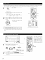
AV SURROUND
RECEIVER
AVR-2803/983
OPERATING INSTRUCTIONS
O
•
•
O
O
O
We greatly appreciate your purchase of the AVR-2803/983.
To be sure you take maximum advantage of all the features the AVR-2803/983
has to offer, read these
instructions carefully and use the set properly. Be sure to keep this manual for future reference, should any
questions or problems arise.
"SERIAL NO,
PLEASE RECORD UNIT SERIAL NUMBER ATTACHED TO THE REAR OF THE
CABINET FOR FUTURE REFERENCE"
• SAFETY PRECAUTIONS
CAUTION
TO PREVENT ELECTRIC SHOCK, MATCH WIDE BLADE OF PLUG
TO WIDE SLOT, FULLY INSERT.
WARNING:
TO PREVENT FIRE OR SHOCK HAZARD, DO NOT EXPOSE
THIS APPLIANCE TO RAIN OR MOISTURE.
ATTENTION
POUR EVITER LES CHOCS ELECTRIQUES, INTERODUIRE LA
LAME LA PLUS LARGE DE LA FICHE DANS LA BORNE
CORRESPONDANTE DE LA PRISE ET POUSSER JUSQU' AU
FOND.
CAUTION:
TO REDUCE THE RISK OF ELECTRIC SHOCK, DO
NOT REMOVE COVER (OR BACK). NO USERSERVICEABLE PARTS INSIDE. REFER SERVICING
TO QUALIFIED SERVICE PERSONNEL.
This
device
the
following
complies
interference,
The lightning flash with arrowhead symbol, within an
equilateral triangle, is intended to alert the user to the
presence of uninsulated "dangerous voltage" within
the product's enclosure that may be of sufficient
magnitude to constitute a risk of electric shock to
persons.
including
This
and
Class
point within
an equilateral
(2} this
B digital
Interference-Causing
Get appareil
15 of the
(1)
device
that
may
FCC
This
must
cause
accept
meets
Regulations
de
la classe
brouilleur
all
Operation
may
any
undesired
apparatus
le matebel
Rules
device
Equipment
numebque
sur
Par[
conditions:
interference
Reglement
The exclamation
with
two
not
is subject
cause
interference
recewed,
operation
requirements
B respecte
of
toutes
the
les
Canadian
exigences
du Canada
triangle is
intended toand
alertmaintenance
the user to the
presenceinstructions
of importantin
operating
{servicing)
the literature accompanying the appliance.
• NOTE ON USE / OBSERVATIONS
RELATIVES A L'UTILISATION
2,
•
•
•
•
Avoid
high temperatures
Allow
for sufficient
installed
on a rack
heat
Evter
Tenir
6levees
disperson
des temperatures
compte
d'une
suffisante
dispersion
lots de I'installation
de
Keep
dust
the
set
free
from
water,
and
•
•
DO not let fore gn obiects in the set
Ne pas laisser
des objets
6trangers
darts
I'appareil
Proteger
]'appareil
lapoussiere
contre
I'humidit6,
I'eau
et
when
chaleur
sur une _tag_re
•
Handle the power cord carefully
Hold the plug when unplugging
•
Manipuler
le cordon
d'alimentation
avec
pr6caution
Tenir la prise lots du d@blanchement
du cordon
the
•
Unplug
•
for long periods
Debrancher
le
the power
of tree
cordon
I'appareil
periodes
pas utilise
n'est
cord
when
not using
d'alimentation
pendant
the
•
DO not let [nsecticdes,
benzene,
come in contact wth the set
•
Ne pas mettre
set
Iorsque
benzene
en contact
et un diluant
avec
and thinner
des insecticides,
du
I'appareil
de Iongues
cord
* (For sets with
2
moisture,
ventilation
•
Do not obstruct
the ventilation
•
Ne pas obstruer
les trous
holes)
holes
d'a6ration
disassemble
to
harmful
•
Never
•
way
Ne iamais
d_monter
ou modifier
d'une mani_re ou d'une autre
or modify
the
set
in any
I'appareil
du
SAFETY INSTRUCTIONS
1.
Read Instructions - All the safety and operating
should be read before the product is operated.
instructions
13.
Power-Cord Protection - Power-supply cords should be routed
so that they are not likely to be walked on or pinched by items
placed upon or against them, paying particular attention to
cords at plugs, convenience receptacles, and the point where
they exit from the product.
2.
Retain Instructions - The safety and operating
should be retained for future reference.
instructions
3.
Heed Warnings - All warnings on the product
operating instructions should be adhered to.
and in the
4.
Follow Instructions
be followed.
15.
Outdoor Antenna Grounding - If an outside antenna or cable
system is connected to the product, be sure the antenna or
cable system is grounded so as to provide some protection
against voltage surges and built-up static charges. Article 810
of the National Electrical Code, ANSl/NFPA 70, provides
information with regard to proper grounding of the mast and
supporting structure,
grounding of the lead-in wire to an
antenna discharge unit, size of grounding conductors, location
of antenna-discharge unit, connection to grounding electrodes,
and requirements for the grounding electrode. See Figure A.
5.
Cleaning - Unplug this product from the wall outlet before
cleaning. Do not use liquid cleaners or aerosol cleaners.
6.
Attachments - Do not use attachments not recommended
the product manufacturer as they may cause hazards.
7.
Water and Moisture - Do not use this product near water - for
example, near a bath tub, wash bowl, kitchen sink, or laundry
tub; in a wet basement; or near a swimming pool; and the like.
16.
Lightning - For added protection for this product during a
lightning storm, or when it is left unattended and unused for
long periods of time, unplug it from the wall outlet and
disconnect the antenna or cable system.
This will prevent
damage to the product due to lightning and power line surges.
17.
Power Lines - An outside antenna system should not be
located in the vicinity of overhead power lines or other electric
light or power circuits, or where it can fall into such power lines
or circuits.
When installing an outside antenna system,
extreme care should be taken to keep from touching such
power lines or circuits as contact with them might be fatal.
18.
Overloading - Do not overload wall outlets, extension cords, or
integral convenience receptacles as this can result in a risk of
fire or electric shock.
19.
Object and Liquid Entry - Never push objects of any kind into
this product through openings as they may touch dangerous
voltage points or short-out parts that could result in a fire or
electric shock. Never spill liquid of any kind on the product.
10. Ventilation - Slots and openings in the cabinet are provided for
20.
ventilation and to ensure reliable operation of the product and to
protect it from overheating, and these openings must not be
blocked or covered. The openings should never be blocked by
placing the product on a bed, sofa, rug, or other similar surface.
This product should not be placed in a built-in installation such
as a bookcase or rack unless proper ventilation is provided or
the manufacturer's instructions have been adhered to.
Servicing - Do not attempt to service this product yourself as
opening or removing covers may expose you to dangerous
voltage or other hazards.
Refer all servicing to qualified
service personnel
21.
Damage Requiring Service - Unplug this product from the
wall outlet and refer servicing to qualified service personnel
under the following conditions:
a) When the power-supply cord or plug is damaged,
b) If liquid has been spilled, or objects have fallen into the
product,
c) If the product has been exposed to rain or water,
d) If the product does not operate normally by following the
operating instructions.
Adjust only those controls that are
covered by the operating
instructions
as an _mproper
adjustment of other controls may result in damage and will
often require extensive work by a qualified technician to
restore the product to its normal operation,
e) If the product has been dropped or damaged in any way, and
f) When the product exhibits a distinct change in performance
- this indicates a need for service.
22.
Replacement Parts - When replacement parts are required, be
sure the service technician
has used replacement
parts
specified by the manufacturer or have the same characteristics
as the original part. Unauthorized substitutions may result in
fire, electric shock, or other hazards.
23.
Safety Check- Upon completion of any service or repairs to this
product, ask the service technician to perform safety checks to
determine that the product is in proper operating condition.
24.
Wall or Ceiling Mounting - The product should be mounted to a
wall or ceiling only as recommended by the manufacturer.
25.
Heat- The product should be situated away from heat sources
such as radiators, heat registers, stoves, or other products
(including amplifiers} that produce heat.
8.
g.
- All operating and use instructions
should
by
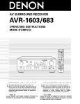
Accessories - Do not place this product on an unstable cart,
stand, tripod, bracket, or table. The product may fall, causing
serious injury to a child or adult, and serious damage to the
product.
Use only with a cart, stand, tripod, bracket, or table
recommended
by the manufacturer, or sold with the product.
Any mounting of the product should follow the manufacturer's
instructions, and should use a
mounting accessory
recommended by the
manufacturer.
A product and cart
combination should be
moved with care. Quick
stops, excessive force,
and uneven surfaces may
cause the product and cart
combination to overturn.
11.
Power Sources - This product should be operated only from the
type of power source indicated on the marking label, if you are
not sure of the type of power supply to your home, consult your
product dealer or local power company. For products intended
to operate from battery power, or other sources, refer to the
operating instructions.
12.
Grounding or Polarization - This product may be equipped with
a polarized alternating-current line plug (a plug having one blade
wider than the other). This plug will fit into the power outlet
only one way. This is a safety feature. If you are unable to
insert the plug fully into the outlet, try reversing the plug. If the
plug should still fail to fit, contact your electrician to replace your
obsolete outlet.
Do not defeat the safety purpose of the
polarized plug.
{NEC ART 25& PART H}
NEC._ATIONALELECTR_CALCODE
3
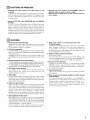
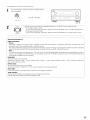
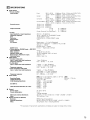
• INTRODUCTION
Thank you for choosing the DENON AVR-2803/983 Digital A / V Surround Receiver. This remarkable component has been engineered to provide
superb surround sound listening with home theater sources such as DVD, as weft as providing outstanding high fidefity reproduction of your
favorite music sources.
As this product is provided with an immense
array of features, we recommend
that before you begin hookup and operation that you review the
contents of this manual before proceeding.
TABLE OF CONTENTS
Before Using ...............................................................................................
4
Surround .............................................................................................
49~54
Cautions on Installation ...............................................................................
4
DSP Surround Simulation
55~60
Cautions on Handling ..................................................................................
5
Ustening
Features ......................................................................................................
5
Last Function
Connections
..........................................................................................
6~13
...................................................................
to the Radio .........................................................................
Initialization
of the Microprocessor
Part Names and Functions ..................................................................
14, 15
Troubleshooting
Setting up the system ........................................................................
16~30
Additional
Remote Control Unit ...........................................................................
31-40
Specifications
Operation ............................................................................................
41-48
61~63
Memory ..............................................................................
63
...........................................................
63
.........................................................................................
Information .........................................................................
64
65~74
............................................................................................
75
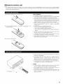
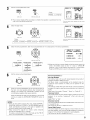
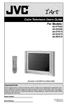
• ACCESSORIES
Check that the following
_ Operating instructions
I
C5_R6P/AA batteries ............. 3
_2_Warranty ( for North America model only ) ....................
_6)AM loop antenna .................. I _ FM indoor antenna
@
[]
parts are included
®
in addition to the main unit:
1
1
C._Service station list ........... 1
®
(4) Remote Control unit
(RC-924) .....................
®
BEFORE USING
Pay attention
to the following
before using this unit:
• Moving the set
TOprevent short circuits or damaged wires in the connection cords,
always unplug the power cord and disconnect the connection cords
between all other audio components when moving the set.
• Store this instructions
in a safe place.
After reading, store this instructions along with the warranty
safe place.
• Before turning the power switch on
Check once again that all connections are proper and that there are
• Note that the illustrations in this instructions
the actual set for explanation purposes,
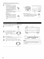
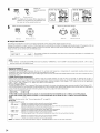
CAUTIONS
ON INSTALLATION
Noise or disturbance of the picture may be generated if this unit or
any other electronic equipment using microprocessors
is used near a
tuner or TV.
If this happens, take the following steps:
• install this unit as far as possible from the tuner or TV.
• Set the antenna wires from the tuner or TV away from this unit's
power cord and input/output connection cords.
• Noise or disturbance tends to occur particularly when using indoor
antennas or 300 _/ohms feeder wires. We recommend using
outdoor antennas and 75 £2/ohms coaxial cables.
For heat dispersal, leave at least 4 inch/10 cm of space between
the top, back and sides of this unit and the wall or other
components.
4
in a
may differ from
not problems with the connection cords. Always set the power
switch to the standby position before connecting and disconnecting
connection cords.
[]
1
4 inch/10 cm or more
[]
CAUTIONS
• Switching
connected
the
ON HANDLING
input
function
when
input
jacks
are
not
A clicking noise may be produced if the input function is switched
when nothing is connected to the input jacks, if this happens, either
turn down the MASTER VOLUME control or connect components
to the input jacks.
• Muting of PRE OUT jacks, HEADPHONE
terminals
• Whenever the power switch is in the STANDBY state, the
apparatus is still connected on AC line voltage.
Please be sure to unplug the cord when you leave home for,
say, a vacation.
jack and SPEAKER
The PRE OUT jacks, HEADPHONE jack and SPEAKER terminals
include a muting circuit. Because of this, the output signals are
greatly reduced for several seconds after the power switch is
turned on or input function, surround mode or any other-set-up is
changed. If the volume is turned up during this time, the output will
be very high after the muting circuit stops functioning. Always wait
until the muting circuit turns off before adjusting the volume.
[]
FEATURES
1. Digital Surround Sound Decoding
Featuring 32 bit high speed DSP, operating entirely in digital
domain, surround sound from digital sources such as DVD, LD,
DTV and satellite are faithfully re-created.
2. DTS 96/24 compatibility
The AVR-2803/983 can be decoded with sources recorded in DTS
96/24, a new multi-channel digital signal format developed by Digital
Theater Systems Inc.
DTS 96/24 sources can be played in the multi-channel mode on the
AVR-2803/983 with high sound quality of 96 kHz!24 bits or 88.2 kHz/24
bits.
3. DTS-ES Extended
Surround and DTS Neo:6
The AVR-2803/983 can be decoded with DTS-ES Extended Surround,
a new multi-channel format developed by Digital Theater Systems Inc.
The AVR-2803/983 can be also decoded with DTS Neo:6, a surround
mode allowing 6.f-channel playback of regular stereo sources.
4. DTS (Digital Theater Systems)
DTS provides up to 5.1 channels of wide-range, high fidelity
surround sound, from sources such as laser disc, DVD and
specially encoded music discs.
5. Dolby Digital
Using advanced
digital processing
algorithms,
Dolby Digital
provides up to 5.1 channels of wide-range, high fidelity surround
sound. Dolby Digital is the default digital audio delivery system for
DVD and North American DTV.
6. Dolby Pro Logic I1 decoder
Dolby Pro Logic I[ is a new format for playing multi-channel audio
signals that offers improvements
over conventional Dolby Pro
8. Wide screen mode for a 7.1-channel sound even with
5.1-channel sources
DENON has developed a wide screen mode with a new design
which recreates the effects of the multi surround speakers in
movie theaters. The result is 7.1-channel
sound taking full
advantage of surround back speakers, even with Dolby Pro Logic
or Dolby Digital/DTS 5.1-channel signals.
g. Multi Zone Music Entertainment
Multi Source Function:
System
This unit's Multi Source function lets you select different audio
sources for listening Different sources can thus be enjoyed in the
main room {MAIN) and the subroom {ZONE 2} simultaneously.
10.Component
Video Switching
In addition to composite video and "S" video switching, the AVR2803/983 provides 2 sets of component video (Y, PB/Cs, PWCR)
inputs, and one set of component video outputs to the television,
for superior picture quality.
11.Video
Select Function
Allow you to watch one source (visual) while listening to another
source (audio).
12.Future Sound Format Upgrade Capability via Eight Channel
Inputs & Outputs
For future muki-channel audio format(s), the AVR-2803/983 is
provided with 7.1 channel {seven main channels, plus one low
frequency effects channel) inputs, along with a full set of 7.1
channel pre-amp outputs, controlled by the 8 channel master
volume control. This assures future upgrade possibilities for any
future multi-channel sound format.
Logic. It can be used to decode not only sources recorded in Dolby
Surround but also regular stereo sources into five channels {front
left/right,
center and surround left/right).
In addition, various
parameters can be set according to the type of source and the
contents, so you can adjust the sound field with greater precision.
7. Dolby Digital EX decoder system
Dolby Digital EX is a 6.1_channel surround format proposed by
Dolby Laboratories that allows users to enjoy in their homes the
"DOLBY DIGITAL SURROUND EX" audio format jointly developed
by Dolby Laboratories and Lucas Films and first used for the movie
"Star Wars Episode 1 - Phantom Menace".
The 6.1 channels of sound, including surround back channels,
provide improved sound positioning and expression of space.
5
[]
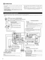
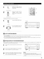
CONNECTIONS
• DO not plug in the AC cord until all connections
have been
completed.
• Be sure to connect the left and right channels properly (left with
left, right with right).
• Insert the plugs securely. Incomplete connections will result in the
generation of noise.
• Use the AC OUTLETS for audio equipment only. Do not use
them for hair driers, etc.
• Note that binding pin plug cords together with AC cords or placing
them near a power transformer will result in generating hum or
other noise.
• Noise or humming may be generated if a connected
audio
equipment is used independently without turning the power of this
unit on. If this happens, turn on the power of the this unit.
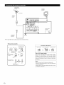
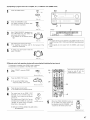
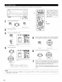
• When making connections, also refer to the operating instructions of the other components.
The power to these outlets is turned on and off when the power is switched between on and standby from the remote control unit or power
switch.
OUTPUT
CD
player
{Connecting
Turntable
(MM car tlidge)
[ Connecting
Connect
jack
the
a turntable
tumtable's
the
AC OUTLETS
]
AC OUTLETS
• SWITCHED
]
Output cord
to the
(total capacity
/20 W {1 A ))
The power to these Outlets Js turned on arid off in coniunct_on w_th the
POWER operation switch on the main unit, and when the power is switched
between on and standby from the remote control unit
AVR
the R {rlght) plug to the right iack
NOTE:
This unit cannot be used with MC cartlidges
direc6y Use a separate head amplifier or step up
transfotmer
_
driers,
i gg3/g63's
L (lee} plugwhen
10 thetheL
If
humrrfing PHONO
or othel iac_'s'
noise the
is generated
ground
w_re
w_re is conrlecled,
disconnect
TVs ot other electrical
appliances
the grourld
Connecting
the
pre-out
jacks
Use these iacks if you wish to connect external power amplifier(s)
increase the power of the eont, center and surlourld sound cllar/rlels,
fol connection to powered loudspeakers
TO use Surround bac_, with
SURR BACK L CH
one speaker,
way that they do not obstruct the ventilation
Route the connection
cords, etc, in such a
holes
[TRIGGER
OUTPUT
corlnect
the
speaker
to
or
to
AC 120 V 60 Hz
_
OUT]
Turn the DC 12V voRage on and off for the indMdual functions
For detai_s, see "6ettlrlg the Trigger Out Setup" oil page 28
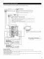
MD recorder, CD recorder or other component
equipped with digita_ input/output
jacks
CD recorder
or Tape deck
NOTE:
R
[ Connecting
the
DIGITAL
Use these for coi!nections
instruct_oiis oil setting
6
jacks
to audio equipment
tllJs tetmina_
_NPUT
]
with digital output
Refel to page 23 for
L
R
C
OUTI_U
0oo
r
_
_@
_
_
[Connecting
a tape
away
deck]
Connections
for recording:
Connect tile tape deck's recording fflpu_ iacks (LINE _N or REC) to this url_t's tape
recording {CDR/TAPE OUT) jacks using pin plug cords
Connections
for playback:
Connect the tape deck's playback output jacks (LINE OUT or PB) to this urlJt's tape
playback (CDR/TAPE IN) jacks using pin plug cords
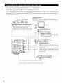
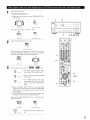
• TO connect the video signal, connect using a 75 _2/ohms video signal cable cord. Using an improper cable can result in a drop in video quality.
• When making connections, also refer to the operating instructions of the other components.
TV or DBS tuner
I Connecting
a TV or DBS tuner
I
MONITOR OUT
• Connect the TV's video input iack (VIDEO INPUT} to the
MONITOR OUT iack using a 75 _/ohms video coaxial pin plug
cord
Note on connecting
the digital input jacks
• OnlYFor
details,aUdi°
signalSsee
pageare6inputto the digital input iacks
I Connecting
a video decks]
• There are two sets of video deck (VCR) jacks, so two video decks can be connected for simultaneous recording or video copying
Video input/output
connections:
• Connect the video deck's video output jack (VIDEO OUT) to the _
(yellow) VCR-1 IN iack, and the video deck's video input iack (VIDEO IN) to the
(yellow) VCR-1 OUT jack using 75 OJohms video coaxial pin plug cords
Connecting the audio output jacks
• Connect the video deck's audio output jacks (AUDIO OUT) to the _
VCR-1 IN jacks, and the video deck's audio input iacks (AUDIO IN) to the _
OUT iacks using pin plug cords
Connect the second video deck to the VCR-2 jacks in the same way
VCR-1
7
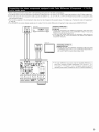
• When making connections, also refer to the operating instructions of the other components.
• A note on the S input jacks
The input selectors for the S inputs and Video inputs work in conjunction with each other.
• Precaution when using S-jacks
This unit's S-jacks (input and output) and video pin jacks (input and output) have independent circuit structures, so that video signals input from
the S-jacks are only output from the S-jack outputs and video signals input from the pin iacks are only output from the pin jack outputs.
When connecting this unit with equipment that is equipped with S jacks, keep the above )oint in mind and make connections according to the
equipment's instruction manuals.
Connecting a monitor
MONITOR OUT
DVD player or video disc player (VDP)
• Connect the TV's S video input (S-VIDEO INPUT) to the _
OUT iack using a Siack connection cord¸
Is
Connecting
DVD
a DVD player or a video disc player (VDP)
TV]
Montor
]
• Connect the DVD player's SWideo output jack to the S-VIDEO
DVD iN iack using a S-Video connection cord
• A VDP can be connected to the VDP jacks in the same way
• It is also possible to connect a video disc player, DVD player,
video camcorder, game machine, etc, to the VAUX jacks
MONITOR
TV or
sateJ_ite
bloadcast
_uooo(
turner
Joo
EConnecting
a TV or DBS tuner ]
• Connect the TV's or DBS tuner's S video output jack (SVIDEO OUTPUT) to the _
TV or DBS IN iack
using an S-Video connection cord
Video deck 1
_@
@"
9@,.
(
I Connecting
g@-
• Connect
the video decks I
the video deck's
S output
jack {S-OUT) to the
VCR-1 IN jack and the video deck's S input iack
(SdN) to the
connection
,,.D "@@" @@_
• Connect
_
VCR-I
OUT iack
using
S-Video
cords
the video deck's
S output
jack {S-OUT) to the
VCR-2 IN jack and the video deck's S input iack
(SdN) to the
"@'@ @' @@_'_
connection
_
VCR-2
OUT iack
using
cords
Video deck 2
Connect the components'
8
audio inputs and outputs
as described on page 7
]
S-Video
• When making connections, also refer to the operating instructions of the other components.
• The signaEs input to the color difference (component) video jacks are not output to the VIDEO output jack (yellow) or the S+Video output jack.
• Some video sources with component video outputs are Eabeled Y, CB, CR, or Y, Pb, Pr, or Y, R+Y,B+Y.These terms all refer to component video
color difference output.
• The function assigned to the component video input can be changed at the system setup. For details, see "Setting the video In Assignment"
on page 24.
• The AVR+2803's on+screen display signals are not output from the color difference {component) video output jacks {MONITOR OUT).
VIDEO OUT
DVD player
+++++I+
Connecting
r++++,
l++
Monitol
COMPONENT
VIDEO iN
Y
C_ CA
a DVD player
]
DVD IN jacks
• Connect the DVD player's color
(COMPONENT VIDEO OUTPUT)
75 _dohms coaxial video pin-ptug
• In the same way, another video
as a TV/DBS tuner, etc, can be
(componentl video jacks¸
difference (component) video output iacks
to the COMPONENT VtDEO-I tN iack using
cords¸
source with component video Outputs such
connected to the VEDEO-2 color difference
TV
Connecting
a monitor +IV ]
MONITOR OUT jack
• Connect the TV's color difference (component)
video input iacks
(COMPONENT VIDEO INPUT) to the COMPONENT MONETOR OUT
jack using 75 OJohms coaxiaE video pimplug cords¸
• The color difference input jacks may be indicated differently on
some TVs, monitors or video components ("CR, CB and Y', "RY, B-Y and Y", "Pr, Pb and Y", etc.). For details, carefully read the
operating instructions included with the TV or other component.
9
DIRECTIONOF
BROADCASTING
STATION
AM LOOP
ANTENNA
(Supplied)
J
FM ANTENNA
75 _fohms
COAXIAL
CABLE
AM OUTDOOR
ANTENNA
Y///
FM_NDOOR
ANTENNA
GROUND
{Supplied)
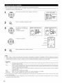
• An Ftype FM antenna cable plug can be connected
AM
loop
antenna
directly.
assembly
Connect to the AM
antenna tetmi_a_s
Connection
Pusll
tfle
_ever
2
Insert
=>
and take out the
(_
connec_]or_ _ine
With the antenna
on to[) any stable
surface
Mount
of AM antennas
tfle
conductor
3
Return
the
]ever
=>
Bend in the reverse
direction
Note to CATV system installer:
This reminder is provided to call the CATV system installer's
attention to Ar[icle 820-40 of the NEC which provides
guidelines for proper grounding and, in par[icular, specifies
that the cable ground shah be connected to the grounding
system of the building, as close to the point of cable entry
as piactical
Notes:
• DO not connect two FM antennas simultaneously
• Even if an external AM antenna is used, do not disconnect
the AM loop antenna
• Make sure AM loop antenna lead terminals
metal parts of the panel
10
do not touch
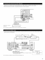
• These jacks are for inputting multi-channel audio signals from an outboard decoder, or a component with a different type of multi-channel
decoder, such as a DVD Audio player, a multi-channel SACD player, or other future multi-channel sound format decoder.
• When making connections, also refer to the operating instructions of the other components.
_L
analog
Dec°derwitha-°r6-channeJI
output
For instructions
Ez
__1
o
on playback using the external input (EXT. IN) jacks, see page 44.
• if another pre-main (integrated) amplifier or power amplifier is connected,
ZONE 2 the same time. (See page 48)
the ZONE 2 jacks can be used to play a different program source in
RC4_16
ZONE
Integrated
2
pre main amplifier
INFRARED
INFRARED
£ENSOR OUTPUT
RC617
iNPUT
t
D_N
R_TRANS
MITFE
R
AUX
°ooo
_
°
OUT
00'
Extension jacks for future use
-SERIAL
• Connect
CONTROL
when
terminal
using
• Use an adapter
cable
conllect
the exte[nal
For instructions
on operations
an external
RS2320
Serial Control cable
--
GND
Controller
(sold separately)
cont/oller
as shown
on the
diagram
at the
dght
to
TXD
RXD
(PC OUT) (PC IN)
using the ZONE 2 jacks, see page 47, 48.
11
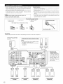
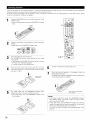
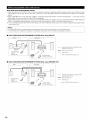
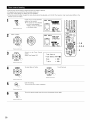
• Connect the speaker terminals with the speakers making sure that like
polarities are matched (® with ®, ® with O ) Mismatching
of polarities will
result in weak central sound, unclear orientation of the various instruments,
and the sense of direction of the stereo being impaired
• When making connections, take care that none of the individual conductors
of the speaker cord come in contact with adjacent
terminals, with other
speaker cord conductors, or with the rear panel
Speaker
•
Impedance
Speakers
with
use as front
•
•
an impedance
and center
Speakers
with
surround
speakers¸
Be careful
since
an impedance
when
using
use of speakers
of from
6 to
16 _/ohms
can be connected
for
speakers¸
of 6 to 16 _/ohms
two
pairs
with
an impedance
of front
can be connected
speakers
{A + B) at the
of less
than
g _/ohms
for use as
same
will
time,
lead
to
damage¸
NOTE:
•
NEVER touch the speaker ter minals when the power
Doing so could result in electric shocks
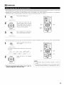
Either tightly
2 Insert the cord
twist
or terminate
protector
at
specified
Connection
1 Loosen by turning
counterclockwise
The
time
is on
high
circuit
volumes
impedance
may
be activated
when
speakers
if the
set
with
an
is played
impedance
for
long
periods
lower
than
of
the
are connected¸
the speaker terminals
3 lighten by turning
clockwise
Connecting
banana plugs
the core wires,
banana plug
Turn_
insert
the banana
plug¸
Connections
• When making connections,
also refer to the operating instructions
Connection iack for subwoofer
with built-in amplifier
(super
woofer), etc
I SURROUND
BACK/ZONE
of the other components.
2 SPEAKER SYSTEMS
I
NOTES:
• TO use Surround back with one speaker, connect
the speaker to SURR BACK L CH
• The settings must be changed to use this speaker
for ZONE 2
See page 25
• Precautions when
connecting speakers
If a speaker is placed near a
TV or video monitor, the
colors on the screen may
be
disturbed
by
the
speaker's
magnetism
If
this should happen, move
the speaker
away to a
position where it does not
have this effect
][
SURROUND SPEAKER
SYSTEMS
12
FRONT SPEAKER
SYSTEMS (B)
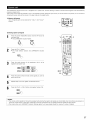
• This unit is equipped with a high-speed protection circuit. The purpose of this circuit is to protect the speakers under
circumstances such as when the output of the power amplifier is inadvertently short-circuited and a large current flows, when
the temperature surrounding the unit becomes unusually high, or when the unit is used at high output over a long period
which results in an extreme temperature rise.
When the protection circuit is activated, the speaker output is cut off and the power supply indicator LED flashes. Should
this occur, please follow these steps: be sure to switch off the power of this unit, check whether there are any faults with
the wiring of the speaker cables or input cables, and wait for the unit to cool down if it is very hot. improve the ventilation
condition around the unit and switch the power back on.
if the protection circuit is activated again even though there are no problems with the wiring or the ventilation around the
unit, switch off the power and contact a DENON service center.
• The protector circuit may be activated if the set is played for long periods of time at high volumes when speakers with an
impedance lower than the specified impedance (for example speakers with an impedance of lower than 4 _/ohms) are
connected, if the protector circuit is activated, the speaker output is cut off. Turn off the set's power, wait for the set to cool
down, improve the ventilation around the set, then turn the power back on.
13
[]
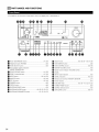
PART NAMES
AND FUNCTIONS
• For details on the functions of these parts, refer to the pages given in parentheses
().
DEN _ _
mu_,iE
DTS
°°°
0
i
11
O
_
Power ON/STANDBY
switch ..............................................
(45)
VIDEO SELECT button .............................................................
(45}
Front speaker system indicators
(FRONT SPEAKER A/B)
FRONT SPEAKER button ...................................................
(41, 63)
ZONE 2 button/indicator
.....................................................
_)
14
SELECT knob ...........................................
_}
(43, 45, 50 _ 54, 57, 59}
TONE DEFEAT button ..............................................................
TONE CONTROL button ....................................................
(45}
(45, 59)
_)
MASTER VOLUME control ......................................................
(43)
_)
Master volume indicator (VOLUME
{43)
LEVEL) ............................
Display
(47, 63)
i_
INPUT mode indicators ............................................................
(42, 44, 53)
i_
SIGNAL indicators ..............................................................
ANALOG button .................................................................
(42, 44)
i_
Remote control sensor (REMOTE SENSOR) ...........................
(31)
EX_. IN button ....................................................................
(42, 44)
Power indicator ........................................................................
{41 }
MODE button ...............................................................
_)
(41, 63)
Headphones jack (PHONES) ....................................................
DIMMER
button .......................................................................
(46)
FUNCTION knob ......................................
STATUS button .........................................................................
(46)
TUNING PRESET button ..........................................................
SURROUND
BACK button .......................................................
(53)
SOURCE selector button .........................................................
SURROUND
MODE button .............................
SURROUND
PARAMETER button .........................
(43, 50, 52, 53, 57)
{51, 52, 54, 57)
i_
(43)
(43, 53}
(42, 45 _ 47, 53, 61, 63)
ZONE 2/REC button ...........................................................
{63)
{42}
(46, 47)
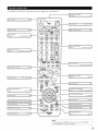
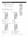
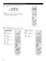
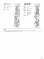
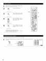
• For details on the functions of these parts, refer to the pages given in parentheses
().
[
BLED (indicator) ........................................
(36) I
.............................
•
(31) I
i
I Power buttons ..................... (33-35,
,......
"z_iE'2
......
"----'-'--'I
i
OFF
GII
l ZONE 2 buttons
.....................................
,;"" "z'o_rl_t_)""" "; ,
,i
OFF
ON
'
"._ _):.(_
(47) l-
Ib%::!::t:
................
,32_3436_4,
47,1 ' _
,"
MODE
MEMO_
buttons
(47)
I
©',,
i
_'_jq
/WVOL,
@ @i',
vop
i
i
i
i
_sx : :
(_ (_
.................... (33~35, 42, 47, 53, 61)
..........................
'
ii
ii
ii
Ilnp
0tsou,oese,ecto, I_
buttons
SHIFT 1
...........
"" Prlbmff"""" "Cb.....
eve
I ZONE1
(MAIN)
i
BAND
t©..0..Q
I
_._
(_D C_
',
37-41 ) I
(_::
Tuner system/System
I buttons ...........................
i
i
i
i
i
i
i
I
',
"
i I
(32,35,47,61-63)
I
(bCbCb
1Y
1188
CDRT/12E
i :
i
',l
• ¢,.L_Z.._:=_;;
i
SELECT button ...........................
(32) I
SU_UND_SC
\
(:_ (:_ (_
0,,m
i
SMULATO.'
',
(:_,
i
c:)i i
_
r
buttons .............................................
e_scsm+
:
""_""
: ...."_
_''[
I
su "'_''"
1""
: C_=N6
_--_
,_u,
_?__..
I
button
{34, 35, 46) 1
I TEST TONE button .................................
I sYSTEM
CALL butt°nS
mUSE/LEARN button
..........................
..........................
I
(49) I
(37)
1_-!;
(36, 39) I
ION
S_V_N _
I
.
I
......
t
,
I
,MUTlNGbutton
(43, 47)
I button .......................
I
--
(16, 49, 50) 11I
RETURN button ................................
FRONT/
_
:[N_T"
--
,_IIRROIIND
,
(:_)_-_
.......
_il
_
/@ DENON
(Nothing
_
(34, 35)
IFRONTSPEAKER
b°_on.......................
(41)I
,
SURROUND
BACK button ..................... (53)
INPUT MODE selector
NOTE:
• The shaded button
(45)
(34, 5I, 52, 54, 56, 58) I
I CH
...................................................
SELECT/ENTER button
-__
: (_: _)
,
I --::--',; ......
I
......................................
iSURROUND
PARAMETERi
\_MENU
,.._;_._.,._
|
I
\i
SETUP
_/'"
"_'_,
__)])/
ION SCREEN/DISPLAY
I
%.C.zJi
I
:
I
........
Master volume control
Ale * ,
"
I
I
L,:::::::::::::::::::::::
CHANNEL
+
4o. ggg2g3g6J
Surround buttons
m,Eo _&_co":i
• _L_ c) o
,
I System buttons .................... (32, 34, 35, 38)I"
J,W.-.-.,
ii
\
\
I MODE
N
ii
do not function
I
(42, 44) I
with the AVR-2803/983
happens when they are pressed)
15
[]
SETTING
UP THE SYSTEM
• Once all connections with other AV components have been completed as described in "CONNECTIONS" (see pages 6 to 13), make the various
settings described below on the monitor screen using the AVR-2803/983'S on-screen display function.
These settings are required to set up the listening room's AV system centered around the AVR-2803/983.
• Check that the remote control unit is set to AMP mode {TAPE, CDR/MD or CD).
• The system settings can be reset to the default {factory shipment) settings by initialization of the microprocessor (see page 63).
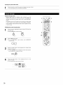
• Use the following buttons to set up the system:
_s
t
SETU P button
to display the system setup menu.
R buttons
1
Use these to move the cursors (< and I_) to the left I
and right on the screen.
/
: Use these to move the cursors (A and ,} to the upl
and down on the screen.
|
I
ENTER button
Press this to switch the display.
A so use th s button to compete
the setting.
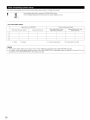
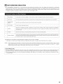
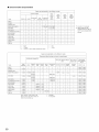
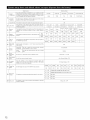
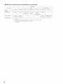
• System setup items and default values {set upon shipment from the factory)
System
Speaker
Configuration
Crossover
setup
Default
Input the combination
of speakers
in your system
and their
corresponding
sizes {Small for regular speakers, Lalge for full size,
fu_] range) to auton,aticaHy set tile composltion of the slgnals output
from the speakers and the frequency response
Ftequency
Set the frequency (Hz) below which the bass sound of the vanous
speakers is to be output from the subwooter
Su#w0ofe rr0de
This selects the subwoofer
Delay %me
This parameter is for optimizing the timing with which the audio
slgna_s are produced from the speakers and subwoofer
accotding to
the listening position
Channel
Level
speaker
for playing
Front Sp
Center Sp
Sub Woofer
Large
Smal_
Yes
Sp
Small
Surround
Back Sp
Small / 2spkls
LFE
Front L & R
Surround
12 It (36 m)
Front L
L & R
/0 ft (3Ore)
SBL & SBR
10 ft {3 0 ml
Front
i_/und
OdB
CD
Digital _n
Assignment
Surround
80 Hz
deep bass signals
This adiust s the volume of the signals output from the speakers and
subwoofer
for the different
channels irl order to obtain optimum
effects
settings
COAX1
Subwoofer
OdB
0dB
I
DVD
VCR 2
TAPE
OFF
OPT4
I COAX2
I
This assigns
the different
the color difference
input sources
Turn the audio
Digital signals
compression
(component)
video
on or off when
down
mixing
Ext
sets
In Subwoofer
surround
whether
on
unit
the
or
not
monito¢
or main
unit
terminal
p_ayback
level
NONE
OFF
Subwoofer
mode function
Back
+lSdB
Auto Surround
to
display
the
screen
when
the
are
Set the Trigger Out output
16
I
Variable
Set the Auto
control
VIDEO1
Surlouiid
Zone2
vol Level
appea_s
VDP
Dolby
Assignment
This
I
input jacks for
Power AMP
Set the
DVD
on_creen
controls
display
on
operated¸
for the different
input
sources
the
Mode = ON
that
remote
On Screen
Display
ON
System
@
_
Auto Tuner
Presets
Setup Lock
setup
FM stations are received
Defauk
automatically
Set whether or not to lock tile system
ca_mot be changed
and stored it1 the memory
setup settlrlgs
settings
A1 -- A8
87 5/89 1/98 1/107 9/901/901/90//90/
B1 -- B8
520/600//000/1400/1500//710
C1 -- C8
90 1 MHz
D1 -- D8
90 1 MHz
E1 -- E8
90 1 MHz
so that they
MHz
kHz, 90//90/
MHz
Setup Lock = OFF
NOTES:
• The on-screen display signals are output with priority to the S-VIDEO MONITOR OUT jack during playback of a video component. For example,
if the TV monitor is connected to both the AVR-2803/983'S S-Video and video monitor output jacks and signals are input to the AVR-2803/983
from a video source (VDP, etc.) connected to both the S-Video and video input jacks, the on-screen display signals are output with priority to
the S-Video monitor output. If you wish to output the signals to the video monitor output jack, do not connect a cord to the S-VIDEO
MONITOR OUT jack. (For details, see page 30.)
• The AVR-2803/983'S on-screen display function is designed for use with high resolution monitor TVs, so it may be difficult to read small
characters on TVs with small screens or low resolutions.
• The setup menu is not displayed when headphones are being used.
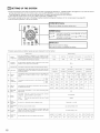
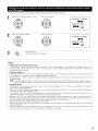
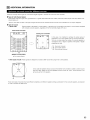
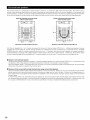
• Speaker system layout
Basic system layout
• The following is an example of the basic layout for a system consisting
Subwoofer
of eight speaker systems and a television
monitor:
Center speaker system
Surround back speaker systems
__
Front speaker systems
Set these at the sides of the TV or screen with
Surround speaker systems
their front surfaces as flush with the front of the
screen as possible
• Before setting up, connect the AVR-2803/983's
connected to the AVR-2803/983's
Check that all the connections
SETUp
MONITOR OUT connector
video input connectors.
(For instructions
with the monitor TV and turn off the power of all playback devices
on connecting
the monitor TV, see page 7 and 8.}
are correct, then turn on the main unit's power.
Display the System Setup Menu.
To stop system setup before it is completed,
System setup can be stopped
press the system setup button again.
at any time.
System
Setup
Menu
_Speaker
Configuration
Delay Time
Channel
Level
Digital
In Assignment
Video
In Assignment
Dolby
Digital
Setup
Zone2 Control
The changed settings are stored and the on screen display turns off.
• if you make a mistake at a system setup setting, you can reset it by selecting the desired menu from the System Setup Menu screen. The
settings that have been changed up to that point are stored.
17
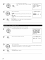
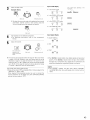
• Set up in function of your speaker systems. Performing this setup optimizes the system.
• The composition of the signals output to the different channels and the frequency response
combination of speakers actually being used.
1
are adjusted
automatically
At the System Setup Menu select "Speaker Configuration".
System
according
Setup
to the
Menu
7Speaker
Configuration
Delay Time
Channel
Level
Digital
In Assignment
Video
In Assignment
Dolby
DlKital
Setup
Zone2 Control
_,_
Switchtothespeakerconfigurationscreen.
Set whether or not speakers are
connected and, if so, their size
Speaker
parameters.
• To select the speaker
ConfiEuration
_Front
Center
"Speaker
Configuration
Surround
Sp.
_
Sp.
_s_;_
Sp, Ba_
Subwoofer
G
• To select the parameter
[_
Center Sp
Front Sp
Subwoofer
Surround
Surround
Sp
back Sp
Press the ENTER button to finalize the setting.
NOTE:
I
Select "Large" or "Small" not according to the actual size of the speaker but according to the speaker's capacity for playing low frequency
(bass sound below frequency set for the Crossover Frequency mode and below) signals. If you do not know, try comparing the sound at both
sett ngs sett ng the vo ume to a eve
ow enough so as not to damage the speakers
to determ ne the proper sett rig.
• Parameters
Large ................... Select this when using speakers that have sufficient performance for reproducing bass sound
Crossover Frequency mode.
Small ................... Select this when using speakers that do not have sufficient performance for reproducing bass
for the Crossover Frequency mode. When this is set, bass sound with a frequency below the
Frequency mode is sent to the subwoofer.
When this setting is selected, low frequencies of below the frequency set for the Crossover
to the subwoofer.
None .................. Select this when no speakers are installed.
Yes/No ................ Select "Yes" when a subwoofer is installed, "No" when a subwoofer is not installed.
2spkrs/lspkr.......Set
set for the
sound below the frequency set
frequency set for the Crossover
Frequency mode are assigned
the number of speakers to be used for the surround back channel.
If the subwoofer has sufficient
and surround speakers.
low frequency
playback capacity, good sound can be achieved even when "Small"
For the majority of speaker system configurations,
subwoofer will yield the best results.
18
below the frequency
is set for the front, center
using the Small setting for all five main speakers and Subwooofer
On with a connected
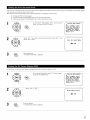
• Set the crossover frequency
Select the "Crossover
and subwoofer
Frequency"
mode according to the speaker system being used.
mode.
Select the frequency.
_Crossover
Frequency
41 l:I']Igl I
Subwoofer
lqil_l
2
Select the "Subwoofer
Mode".
Mode
LFE
+Main
Select the setting.
G
Crossover
Frequency
I I:I']R
_Subwoofer
Mode
Iqi[:ll
LFE
+Main
The System Setup Menu reappears.
(___.
Enter the setting.
NOTES:
-- Assignment of low frequency signal range -• The only signals produced from the subwoofer channel are LFE signals (during playback of Dolby Digital or DTS signals) and the low
frequency signal range of channels set to "Small" in the setup menu. The low frequency signal range of channels set to "Large" are
produced from those channels.
-- Crossover Frequency -• When "Subwoofer"
is set to "Yes" at the "Speaker Configuration Setting", set the frequency (Hz) below which the bass sound of the
various speakers is to be output from the subwoofer (the crossover frequency).
• For speakers set to "Small", sound with a frequency below the crossover frequency is cut, and the cut bass sound is output from the
subwoofer instead.
NOTE: For ordinary speaker systems, we recommend setting the crossover frequency to 80 Hz. When using small speakers, however,
setting the crossover frequency to a high frequency may improve frequency response for frequencies near the crossover frequency.
-- Subwoofer
mode --
• The subwoofer mode setting is only valid when "Large" is set for the front speakers and "YES" is set for the subwoofer in the "Speaker
Configuration" settings (see page 18}.
• When the "LFE+MAIN"
playback mode is selected, the low frequency signal range of channels set to "Large" are produced simultaneously
from those channels and the subwoofer channel.
•
•
•
•
In this playback mode, the low frequency range expand more uniformly through the room, but depending on the size and shape of the room,
interference may result in a decrease of the actual volume of the low frequency range.
Selection of the "LFE " play mode will play the low frequency signal range of the channel selected with "Large" from that channel only.
Therefore, the low frequency signal range that are played from the subwoofer channel are only the low frequency signal range of LFE (only
during Dolby Digital or DTS signal playback) and the channel specified as "Small" in the setup menu.
Select the play mode that provides bass reproduction with quantity.
When the subwoofer is set to "Yes", bass sound is output from the subwoofer regardless of the subwoofer mode setting in surround modes
other than Dolby/DTS.
In surround modes other than Dolby Digital and DTS, if the subwoofer is set to "YES", the low frequency portion is always output to the
subwoofer channel. For details, refer to "Surround Modes and Parameters" on page 60.
19
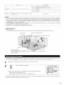
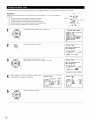
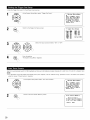
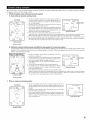
• input the distance between
the listening position and the different
speakers to set the delay time for the surround mode.
Preparations:
Measure the distances between the listening position and the speakers (L1 to L5 on the diagram at
the right).
LI: Distance between center speaker and listening position
L2: Distance between front speakers and listening position
L3: Distance between surround speakers and listening position
L4: Distance between surround back speakers and listening position
L5: Distance between subwoofer and listening position
FL
Center
FR
\
Subwoofer
SBL _
1
At the System Setup Menu select "Delay _me".
SBR
System
Setup
Menu
Speaker
Configuration
_Delay
Time
Channel
Level
DiEital
In Assignment
Video
In Assignment
Oolby Digital
Setup
Zone2 Control
Switch to the Delay _me
screen.
Delay
Time
Set The Distance
Each Speakers
Do You Prefer
In Meters?
/
_Meters
Select the desired unit, meters or feet.
Select (darken) the desired units, "Meters"
Delay
or "Feet".
4:_
To
In Feet?
Feet
Time
Set The Distance
Each Speakers
Do You Prefer
In Meters?
/
_Meters
<:_
Example: When
Once
"Meters"
"Feet" automatically.
is selected in step 3, the
Delay ]]me
screenor appears
Delay
EZFront
Front
Su_0ofer
Center
Select the speaker to be set.
2O
In Feet?
F-_
"Feet"
is selected
Delay Time
Time
Default
To
[_4
L 112ft_
R 12ft
1 2 ft
12ft
SL
SBL
SBR
SR
<10ft_
10ft
10ft
10ft
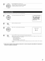
Set the
distance
center
speaker
position.
between
and
the
Delay
listening
Delay Time
Time
Default
The distance changes in units of
1 foot (0.1 meters) each time the
, Front
,_Center
Front
button
_s pressed. Select the
value closest to the measured
distance.
[_4
12ft
<12ft_
L
12ft
Example:When
the distanceis
forthe centerspeaker
If "Yes" is selected for "Default",
to the default values.
Please note that the difference
20 ft (6.0 m} or less. If you set
such as screen right will appear.
speaker(s) so that its distance
highlighted
__\
SR
SBL
SBR
ETSL
R
setto
the settings are automatically
1Oft
1Oft
1Oft
<10ft_
12 feet
reset
Default
of distance for every speaker should be
an invalid distance, a CAUTION notice,
In this case, please relocate the blinking
is no larger than the value shown in
[_4
Front
R
12ft
Center
lft
Front
L
12ft
B'_111tfl
DNilI!
line.
The System Setup Menu reappears.
The
EnterAVR-2803/983
the setting. automatically sets the optimum
surround delay time for the listening room.
NOTE:
• If the distance unit is changed after the delay time is set, the settings are reset to the factory default values (see page 16, 17}.
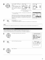
• Use this setting to adjust so that the playback level between the different channels is equal.
• From the listening position, listen to the test tones produced from the speakers to adjust the level.
• The level can also be adjusted directly from the remote control unit. (For details, see page 49.)
1
At the System Setup Menu select "Channel
Level".
System
Setup
Menu
Speaker
Configuration
Delay Time
_Channe I Level
Digital
In Assignment
Video
In Assignment
Dolby
DiKital
Setul0
Zone2 Control
Switch to the Channel Level screen.
Channel
Level
_Test
Tone
_4:_
Test
Tone
Start
Level
Clear
[_<
[_4
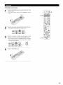
Select "Test Tone".
21
Select the mode.
Select "Auto" or "Manual".
• AUTO:
4
Channel
Level
i
Adjust
the level while
Eistening to the
autematicaEly from the different speakers.
• Manual:
Select the speaker from which
adjust the level.
test
tones
,_Test
Tone
_4:_
Test
Tone
Start
produced
Level
Clear
[)_<
[i_4
you want to produce the test tone to
Example: When the "Auto"
mode is selected
Select "Test Tone Start".
Channel
Test
Tone
_4:_
_Test
Tone
Start
Level
7
a. if the "Auto"
Level
Clear
[%_4
[_4
mode is selected:
Test
Test tones are automaticaly emitted from the different speakers.
The test tones are emitted from the different
speakers in the
following order, at 4-second intervals the first time and second dme
around, 2-second intervals the third time around and on:
._
Tone
_FL
I spkr
FR
SR
SBR
C
SBL
SL
SW
B
Flashing
<-1 1. 5dB_
0.
0.
0,
0.
0.
0.
0da
0dB
0dB
0dB
0dB
0dB
2spkrs
When
the surround
"Speaker
back speaker
Configuration",
setdng
is set to "lspkr"
for
this is set to "SB".
b
_
_
Use the CURSOR left and right buttons to adjust all the speakers to the
_,:t
\_/
_
/r_]_
"_4"_
same volume.
The volume can be adjusted between
"% osdR
Example: When the volume is set to-115
dB
while
the
test
tone
is being
produced
from
the
Front Lch
speaker
-12 dB and +12 dB in units of
Test
Tone
EFFL
b. When the "Manual"
Use the CURSOR up and down to select
the speaker for which you want to output
test tones, then use the CURSOR left and
right to adjust so that the volume of the
test tones from the various speakers is
the same.
%
_
To cancel the settings,
B
Flashing
FR
SR
SBR
C
SBL
SL
SW
0.
0.
0.
0,
0.
0.
0,
0dB
0dB
0dB
0dB
0dB
0dB
Example: When the volume is set to -t 15 dB
while the Front Lch speaker _s
selected
After
the aboveLevel"
settings
are completed,
The "Channel
screen
reappears. press the ENTER button.
select "Level Clear" and "Yes" on the "Channel Level" screen, then make the settings again.
The level of each channel should be adjusted to 75 dB (C-weighted, slow meter
If a sound level meter is not available adjust the channels by ear so the sound
tone by ear is difficult, use a well known music selection and adjust for natural
NOTE: When adjusting the level of an active subwoofer system, you may also
22
<--11. 5dB)
mode is selected
mode) on a sound level meter at the listening position.
levels are the same. Because adjusting the subwoofer level test
balance.
need to adjust the subwoofer's own volume control.
When you adjust the channel levels while in the SYSTEM SETUP CHANNEL LEVEL mode, the channel level adjustments made will affect
all surround modes. Consider this mode a Master Channel Level adjustment mode.
After you have completed the SYSTEM SETUP CHANNEL LEVEL adjustments, you can then activate the individual surround modes and
adjust channel levels that will be remembered for each of those modes. Then, whenever you activate a particular surround sound mode,
your preferred channel level adjustments for just that mode will be recalled. Check the instructions for adjusting channel levels within each
surround mode on page 49.
You can adjust the channel levels for each of the following surround modes: DIRECT, STEREO, DOLBY/DTS SURROUND, 5/7 CH STEREO
MONO MOVIE, ROCK ARENA, JAZZ CLUB, VIDEO GAME, MATRIX and VIRTUAL.
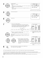
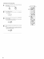
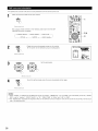
• This setting assigns the digital input jacks of the AVR-2803/983
1
for the different input sources.
At the System Setup Menu select "Digital In Assignment".
System
Setup
Menu
Speaker
Configuration
Delay Time
Channel
Level
ErDigital
In Assignment
Video
In Assignment
Dolby
Digital
Setup
Zone2 Control
2
Switch to the Digital Inputs screen.
Digital
In Assignment
_]:<F_'I_
[_:
COAX2
[_:
OPT1
[_:
OPT2
[_:
OPT3
[_:
OFF
_:
_:
[_:
OFF
OFF
OPT4
Default[_<
Select the digital input jack to be assigned to the input source.
• To select the input source
• To select the digital input jack
Select "OFF" for input sources for which no digital input jacks are used.
•_ If "Yes" is selected for "Default", the settings are automatically reset to the default
values.
The System Setup Menu reappears.
(_
Enter the setting.
NOTES:
• The OPTICAL 4 jacks on the AVR 2803/983's rear panel are equipped with an optical digital output jack for recording digital signals on a CD
recorder, MD recorder or other digital recorder. Use this for digital recording between a digital audio source (stereo 2 channel) and a digital
audio recorder.
• Do not connect the output of the component
the OPTICAL 4 IN jack.
• "PHONO"
and "TUNER"
connected to the OPTICAL 4 OUT jack on the AVR-2803/983's
rear panel to any jack other than
cannot be selected on the Digital in Assignment.
23
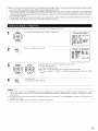
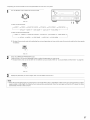
• This setting assigns the color difference
1
(component} video input jacks of the AVR-2803/983
for the different
input sources.
At the System Setup Menu select "Video In Assignment".
System
Setup
Menu
Speaker
Configuration
Delay Time
Channel
Level
Digital
In Assignment
zVideo
In Assignment
Dolby
Digital
Setup
Zone2 Control
2
Switch to the Video In Assignment
screen.
Video
In Assignment
[_:
NONE
[_:
NONE
[_:
VIDEO2
_:
NONE
_:
NONE
[_:
NONE
Default
[_4
Select the component
(Y, PB/C8 and PR/CR)video input terminal to be assigned to the input source.
(_ input source selection
Select "NONE"
for sources for which the component
-_ When the default,
_2_Component
video terminal
selection
(Y, PB/C8 and P£/C£) video input is not to be used.
"Yes", is selected, the settings are reset to the factory defaults.
The System Setup Menu reappears.
4
ENTER the setting.
Sets the down-mixing
OFF:
ON:
1
_
method when not using a center speaker or surround speakers.
The dynamic range is not compressed.
The dynamic range is compressed automatically
according to the combination
At the System Setup Menu select
Setup" and press the ENTER button.
of speakers being used.
"Dolby
Digital
System
Setup
Menu
Speaker
Configuration
Delay Time
Channel
Level
Digital
In Assignment
Video
In Assignment
zDolby
Digital
Setup
Zone2 Control
2
Select
want to"ON"
use it.if you want to use the Compression,
"OFF"
if you do not
When not using a center speaker or surround speakers, the sound is
NOTE:
played from the front speakers. If the sound should seem distorted
because the input level exceeds the allowable input for the front
speakers, set "Compression"
to "ON".
24
Dolby Digital
Downmix Option
Compression
Setup
The System Setup Menu reappears.
Enter the setting.
[1]
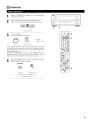
Setting the power amplifier
assignment
Make this setting to switch the power amplifier for the surround back channel to ZONE2.
If ZONE2 is selected, the signal that selected at ZONE2 is output at "SURR. BACK/ZONE2 PREOUT" terminals.
1
At the System Setup Menu select
and press the ENTER button.
"Zone2
Control"
System
Setup
Menu
Speaker
Configuration
Delay Time
Channel
Level
Digital
In Assignment
Video
In Assignment
Dolby
Digital
Setup
_Zone2
Control
2
The "Zone2 Control" screen appears.
Select "Power
Amp Assignment"
and
ENTER button.
press
the
Zone2
_Power
Zone2
Control
Amp Assignment
Vol,
Level
Exit
Select "Surround
Beck" to use as the surround
channel, "Zone2"
to use as Zone 2 out.
back
Power
Amp Assignment
<13fi_f_
: Zone2
When "Surround
(_
[2]
At the "Zone2 Control" screen, select "Exit"
The
Setup Menu reappears.
EnterSystem
the setting.
Power
Amp Assignment
4Surr0undBack
: k'Jli_'J_l_
Back" is selected
When "Zone2"
is selected
and press the ENTER button.
Setting the Zone2 vol. level
Set the Zone 2 pre-out output level adjustment.
At
System
Setup button.
Menu select
and the
press
the ENTER
"Zone2
Control"
System
Setup
Menu
Speaker
Configuration
Delay Time
Channel
Level
Digital
In Assignment
Video
In Assignment
Dolby
Digital
Setup
_Zone2
Control
25
2
The "Zone2 Control" screen appears.
Select "Zone2 VoL Level" and press
button.
the
ENTER
Zone2
Power
_Zone2
Control
Amp Assignment
Vol.
Level
Exit
Select the desired setting.
Zone2
Vol.
Level
Variable:
The level can be adjusted freely using the buttons on the remote control
unit.
_ -40dB
0dB
0 dB, -40 dB:
The output level is fixed at the set level and the volume can no longer be
adjusted.
Enter the setting.
At the "Zone2 Control" screen, select "Exit"
The System Setup Menu reappears.
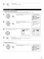
• Set the method of playback of the analog input signal connected
1
and press the ENTER button.
to the Ext.ln Subwoofer.
At the System Setup Menu select "Ext.ln
Subwoofer
Level".
System
Setup
Menu
TExt,
In Subw00fer
Level
Auto Surround
Mode
On Screen
Display
Trigger
Out Setup
Auto Tuner
Presets
Setup
Lock
Switch to the Ext.ln Subwoofer
Level screen.
Ext.
In Subw0ofer
Level
Subw00fer
Lebe I
4+15dB_
Select the desired setting.
Select according to the specifications of the player being used. Also refer to the player's operating instructions.
+15dB {default) recommended. (0, +5, +10 and +15 can be selected.)
Enter the setting.
The System Setup Menu reappears.
26
The surround mode used at last for the three types of input signals shown below is stored in the memory, and the signal is automatically
with that surround mode the next time it is input.
Note that the surround mode setting is also stored separately for the different input sources.
played
_ Analog and PCM 2-channel signals
_2_ 2-channel signals of Dolby Digital, DTS or other multi-channel format
_3_ Multi-channel signals of Dolby Digital, DTS or other multi-channel format
1
At the System Setup Menu select
Mode" and press the ENTER button.
"Auto
Surround
System
Setup
Menu
Ext. In Subw00ferLevel
_Auto
Surround
Mode
On Screen
Display
Trigger
Out Setup
Auto Tuner
Presets
Setup
Lock
Select "ON" if you want to use the auto surround mode, "OFF"
do not want to use it.
if you
Auto Surround
Mode
2
Enter the setting.
The System Setup Menu reappears.
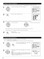
• Use this to turn the on-screen display {messages other than the menu screens) on or off.
1
At the System Setup Menu select "On Screen Display"
and press the ENTER button.
System
Setup
Menu
Ext. In Subwoofer
Level
Auto Surround
Mode
70n Screen
Display
Trigger
Out Setup
Auto Tuner
Presets
Setup
Lock
2
Select "ON" or "OFF".
On Screen
Display
m_ : _[_
The System Setup Menu reappears.
Enter the setting.
27
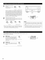
• Sets the Trigger Out output for the different input sources.
1
At the System Setup Menu select "Trigger Out Setup".
System
Setup
Menu
Ext. In Subwo0fer
Level
Auto Surround
Mode
On Screen
Display
7Trigger
Out Setup
Auto Tuner
Presets
Setup
Lock
Switch to the Trigger Out Setup screen.
Trigger
[_:
[_:
[_
Out
_
[_
Setup
_:
_:
: [_
[_
B_
De f au I t[_i]_
Select the input source and select "ON" or "OFF".
EnterSystem
the setting.
The
Setup Menu reappears.
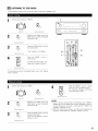
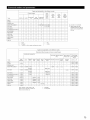
Use this to automatical(y
search for FM broadcasts and store up to 40 stations at preset channels A1 to 8, B1 to 8, C1 to 8, D1 to 8 and E1 to 8.
NOTE:
• if an FM station cannot be preset automatically
using the manual "Preset memory" operation.
1
due to poor reception,
use the "Manual tuning"
At the System Setup Menu select "Auto Tuner Presets".
operation to tune in the station, then preset it
System
Setup
Menu
Ext. In Subwoofer
Level
Auto Surround
Mode
On Screen
Display
Trigger
Out Setup
_Auto
Tuner
Presets
Setup
Lock
Switch to the Auto Preset Memory screen.
Auto
Preset
Auto
Preset
Storing
_Start
28
Memory
Tuning
Station
Preset
[_
&
Memory
Memory
Use the CURSOR button to select "Yes".
"Search" flashes on the screen and searching begins.
"Completed"
appears once searching is completed.
The display automatically switches to screen.
The system setup settings can be locked so that they cannot be changed easily.
1
At the System Setup Menu select "Setup Lock".
System
Setup
Menu
Ext, In Suhw00fer
Level
Auto Surround
Mode
On Screen
Display
Trigger
Out Setup
Auto Tuner
Presets
7Setup
Lock
_
Switch tO the Setup Lock screen.
Select "ON",
to lock the system setup settings.
Press the ENTER to finalize the setting and exit the system setup mode.
When the setup lock function is activated, the settings listed below cannot be changed, and "Setup
displayed when related buttons are operated.
• System setup settings
• Surround parameter settings
Locked"
is
• Tone control settings
• Channel level settings (including test tones)
To unlock, press the System Setup button again and display the Setup Lock screen, then select "OFF" and press
"ENTER".
-_ System setup is complete. Once these settings
connected or the speakers are repositioned.
are made, there is no need to change them unless different
AV components
are
29
This button can be pressed at any time during the system setup process to complete
_
the process.
At the System Setup Menu, press the SYSTEM SETUP button.
s_ue_
,_ The changed settings are entered and the on-screen display turns off.
• On-screen display signals
Signals input to the AVR-2803
On-screen display signal output
VIDEO signal input iack (yellow)
S-video signal input jack
VIDEO MONITOR OUT video
signal output jack {yellowl
S-video MONITOR OUT video
signal output iack
I
x
×
0
0
2
o
×
o
×
3
x
0
x
0
4
O
(}
x
(}
(o: Signal
x: No signal}
(o: On-screen signals output
x: On-screen signals not output}
NOTES:
• The on screen display signals are not output from the color difference (component) video signal MONITOR OUT jacks.
• For 4 above, the on-screen display signals are output to the VIDEO MONITOR OUT video signal output jack (yellow) if the monitor TV is not
connected to the S-video MONITOR OUT video signal output jack.
3O
[]
REMOTE
CONTROL
UNIT
• The included remote control unit (RC-924) can be used to operate not only the AVR-2803/983 but other remote control compatible DENON
components as well. In addition, the memory contains the control signals for other remote control units, so it can be used to operate nomDenon
remote control compatible products.
_
Notes on Batteries
• Use R6P/AA batteries
Remove the remote control unit's rear cover.
in the remote
control unit.
• The batteries should be replaced with new ones approximately
once a year, though this depends on the frequency of usage.
• Even if less than a year has passed, replace the batteries with new
ones if the set does not operate even when the remote control unit
is operated nearby the set. (The included battery is only for venfying
operation. Replace it with a new battery as soon as possible.)
• When inserting the batteries, be sure to do so in the proper
@ Set three R6P/AA
indicated direction.
batteries
in the battery
%
compartment
in the
direction,
following
the "(9" and "0"
marks in the
compartment.
• To prevent damage or leakage of battery fluid:
• Do not use a new battery together with an old one.
• Do not use two different types of batteries.
• Do not short-circuit,
flames.
disassemble,
battery
heat or dispose of batteries in
• Remove the batteries from the remote control unit when you do
not plan to use it for an extended period of time.
• if the battery fluid should leak, carefully wipe the fluid off the inside
of the battery compartment and insert new batteries.
• When replacing the batteries, have the new batteries ready and
insert them as quickly as possible.
%
@ Put the rear cover back on.
• Point the remote control unit at the remote sensor on the main unit
as shown on the diagram.
• The remote control unit can be used from a straight distance of
approximately
23 feet / 7 meters from the main unit, but this
distance will be shorter if there are obstacles in the way or if the
remote control unit is not pointed directly at the remote sensor.
• The remote control unit can be operated at a horizontal angle of up
to 30 degrees with respect to the remote sensor.
NOTES:
23 feet/Approx 7 m
_
• it may be difficult to operate the remote control unit if the remote
sensor is exposed to direct sunlight or strong artificial light.
• De not press buttons on the main unit and remote control unit
simultaneously. Doing so may result in malfunction.
• Neon signs or other devices emitting pulse-type noise nearby may
result in malfunction, so keep the set as far away from such
devices as possible.
31
1
Use the mode selector buttons to select the component
you
want to operate.
-_ The function will change one step in the sequence
described below each time the MODE SELECT button is
pressed.
oooo
_CD
_CDR/MD
ZON E2_TV
_TAPE
_DVD/VDP.
_
DBS/CABLE _
VCR_
1
the audio
•Operate
For details,
refer component.
to the component's operating instructions.
-_ It may not be possible to operate some models.
1. CD player (CD) system buttons
2. _pe
d_k
(TAPE) system buttons
@.¢_¢rq
J
41_1, _
•
I_
rr4141,_
II
: Manual search (forward and reverse)
44
: Rewind
: Stop
I_1_
: Fast forward
: Play
: Auto search (to beginning of track)
: Pause
DISC SKIP +: (for CD changers
3. MD recorder
41_1, _
•
I_
rr4141,_
II
•
I_
n
only)
(MD), CD recorder (CDR) system
: Manual search (forward and reverse)
: Stop
: Play
: Auto search (to beginning of track)
: Pause
_1
A/B
buttons
: Stop
: Forward play
: Pause
: Reverse play
: Switch between
sides A and B
4. Tuner system buttons
TUNING +, BAND
MODE
MEMORY
SHIFT
CHANNEL +, -
: Tuning up/down
: Switch between
: Switch between
AM and FM bands
AUTO and MANUAL
: Preset memory
: Switch preset channel range
: Preset channel up/down
Default setting = CDR
The tuner can be operated
32
in the amplifier
(CD, CDR/MD,
or TAPE) mode
The included remote control unit can be used to operate devices of different brands by registering the preset number corresponding to the brand
of your device.
For some models the remote control unit or the device may not operate properly. In this case, use the learning function {page 36) to store your
device's remote control signals in the included remote control unit.
1
Press the power ON/SOURCE button and the OFF button at
the same time.
• The LEARNED/TX indicator flashes.
1
2
Press
the mode button ofthe equipmentthatis
to a presetrnemory.
• The mode button flashes.
to be entered
C2D (3E) CAD
Referring to the included List of
Preset Codes, use the number
(_)
(_)
@
([_)
@
@
buttons to input the preset code (a
4-digit
number}
for
the
(Z)
@
@
manufacturer
(_)
_.'_
of
the
component
whose
signals you want to store in
the memory.
When
stored indicator
correctly,
the
LEARNED/TX
will light.
mode
To store the codes of another
repeat steps 1 to 4.
component
button
and
the
in the memory,
NOTES:
• Depending on the model and year of manufacture, this function cannot be used for some models, even if the your device is listed on the
included list of preset codes.
• Some manufacturers use more than one type of remote control code. Refer to the included list of preset codes to change the number and
check it out.
• The preset memory
can be set for one component
only among the following:
CDR/MD,
DVD/VDP
and DBS/CABLE.
The preset codes are as follows upon shipment from the factory and after resetting:
TV, VCR ........................................................................
HITACHI
CD, TAPE .....................................................................
DENON
CDR/MD .......................................................................
DVD/VDP ......................................................................
DBS/CABLE .................................................................
DVD preset codes
DENON
Model No.
0000
DVD-900
DVD-1000
DVD-1B00
DVD-2800
DVD-2800I[
DVD-3800
DVD-9000
DVM-1800
DVM-4800
DENON (CDR)
DENON {DVD)
ABC (CABLE}
0001
DVD-800
DVD-1600
DVD-2000
DVD-2500
DVD-3000
DVD-3300
33
Press
the mode selector button for the component
to
operate.
you want
C2D
®®®
NOTE:
• For the DVD player remote control buttons, function names may
differ according to manufacturer.
Compare with the remote
control operation of the various components.
w
m
Operate
the component.
• For details,
refer to the component's operating instructions.
Some models cannot be operated with this remote control unit.
1. Digital video disc player (DVD,
DVD SETUP) system buttons
2. Video disc player (VDP) system
buttons
POWER
: Power on/standby
(ON/SOURCEI
POWER
: Power on/standby
(ON/SOU RCEI
41_1,1_1_
•
: Manual search
(forward and reverse)
: Stop
I_
: Play
14141,1_1_1 : Auto search
II
41_1,1_1_
•
6 66
(to beginning of tlack)
: Pause
®®9
0~9,
+10: 10key
DISC SKIP +: Disc skip
DISPLAY
MENU
RETURN
(for DVD changer only)
: Display
: Menu
: Return
SETUP
ENTER
: Setup
: Enter
A, ¥, _1, I_
: Manual search
(forward and reverse)
: Stop
I_
14141,_
II
: Play
: Auto search (cue)
: Pause
0~9, +I0
: 10key
8 86
®®®W
0_000
: Cursor up, down, left
and right
w
m
=m
0 DEN)_ON
34
o DENON
3. Video deck (VCFI} system
buttons
4. Monitor TV (TV}, digital
broadcast satellite (DBS} tuner
and cable (CABLE} system
buttons
POWER
: Power on/standby
(ON/SOURCE)
41_1,1_
•
I_
II
Channel +, -
: Manual search
(forward and reverse)
POWER
: Power on/standby
{ON/SOU RCE)
MENU
: Menu
: Stop
: Play
: Pause
: Channels
A, V, _1, I_
65"66
ENTER
CHANNEL
0-9, +10
TV/VCR
: Cursor up, down, left
and right
: Enter
: Switch channels
: Channels
: Switch between
6 66
@®@_
TV
and video player
TV VOL +, DISPLAY
RETURN
___
.J
: Volume up/down
: Switch display
: Return
C:2 (:Z) CC)CC)
"8"oE.o.
NOTES:
• For this CD, CDR, MD and TAPE components, buttons can be operated in the same way as for Denon audio components.
• The television can be operated in the DVD/VDP, VCR and TV modes.
35
If your AV component is not a Denon product or if it cannot be operated using the preset memory, it can be controlled with the accessorious
remote control unit by storing its remote control signals in the remote control unit.
For some remote control signals it is not possible to "learn" the signals or the device will not operate properly. In such cases use the remote
control unit included with the device to operate it.
1
Press the USE/LEARN button with the tip of a pen etc., to set
the learn mode.
• Both the mode selector buttons and LEARNED/TX indicator
flash.
Flashes
Press the mode button of the equipment for which learning is
desired.
• Mode button and LEARNED/TX indicator flash.
CABLE
Press the button that is to be learned.
The LEARNEDfrX
indicator stops flashing and the mode
button lights.
• Mode button and LEARNEDfrX indicator flashed if a button
that cannot be "learned" is pressed.
• To cancel, press the USE/LEARN button.
To "learn"
other buttons,
repeat steps 2 to 5.
Pointhold
the in
remote
controlon units
directlyremote
at each
other unit
and which
press
and
the button
the other
control
you want to "learn".
7
!
Other remote
control unit
Once the learning
operation
is completed,
press the
USE/LEARN button again.
The mode button and the LEARNED/TX indicator stop flashing
and the learning mode is cancelled.
_e
The mode button and the LEARNED/TX indicator lights,
release the button on the other remote control unit.
• The mode button and the LEARNED/TX indicator start
flashing again.
stored codes
work properly
NOTES:
• If the codes could not be stored, the LEARNED/TX indicator
start flashing rapidly. For limited number of models, codes
cannot be stored in RC-924.
• If the mode button and LEARNED/TX indicator start flashing
rapidly, this means that the memory is already full, and the code
you have just attempted to store was not stored.
To "learn" that code, first perform the resetting operation. (See
page 39.)
36
The accessorious remote control unit is equipped with "system call" function allowing a series of remote control signals to be transmitted by
pressing a single button.
This function can be used for example to turn on the amplifier's power, select the input source, turn on the monitor TV's power, turn on the source
component's power and set the source to the play mode, all at a signal button.
(1) System call buttons
Up to 10 signals each can be stored at the "CALL1"
buttons.
I
and "CALL2"
k, oo .j
(2) Storing system call signals
1
Press the power ON/SOURCE button and the OFF button at
the same time.
• The LEARNED/TX indicator flashes.
OFF
1
ON/S_JF_
Press
CALLselector
1 button.buttons
• The the
mode
flash.
Press the mode buttons
registered to System Call.
and LEARNED/TX
of the
equipment
indicator
that is to be
(Z2)
CABLE
2,6
6
o_
Press
the by
buttons
store one
one. whose remote control signals you want to
Repeat steps 3 and 4 to register the desired buttons.
Press the CALL1 or CALL2 button and register System Call.
NOTES:
• The remote control signals for the buttons pressed while storing the system call signals are transmitted when the buttons are pressed, so
cover the remote sensor or take other measures so that the components do not operate while the signals are being stored.
• The mode button and LEARNED/TX indicator flashing rapidly if you have already stored the maximum number of signals.
37
(3) Using the system call function
Press
button
at which
the system successively.
call signals have been stored.
• The the
stored
signals
are transmitted
(1) Punch through button
Buttons used in the CD, CDR/MD,
TAPE, DVD/VDP, and VCR
modes can be assigned to the buttons shown on the diagram at
the nght which are not normally used in the TV and DBS/CABLE
modes.
1
For example, when the CD mode is set to the punch through mode
in the TV mode, the CD mode's PLAY, STOP, MANUAL SEARCH,
4
AUTO SEARCH, PAUSE and DISC SKIP buttons'
in the TV mode.
(2) Making the punch through
1
signals are sent
setting
Press the power ON/SOURCE button and the OFF button at
the same time.
• The LEARNED/TX indicator flashes.
2
(1)
(play) button. mode
•Press
TV the
and I_DBS/CABLE
indicator flash.
buttons
and
LEARNED/TX
Press the mode button of the equipment for which Punch
Through is to be set.
• The CD, CDR/MD, TAPE, DVD/VDP, and VCR mode buttons
and LEARNED/TX indicator will flash.
Press
mode button of the equipment
punchedthethrough.
• The mode button that was set will light.
U
38
¸
that
is to be
(1) Resetting
1
"learned"
buttons
Press the USE/LEARN button with the tip of a pen, etc., to set
the learn mode.
• The mode selector buttons and LEARNED/TX indicator
flash.
Hashes
OOOO
Press
the button
mode and
button
of the equipment
is to be reset.
• Mode
LEARNED/TX
indicatorthat
flash.
(ZZ)
CABLE
Hold for 4 seconds or longer the mode button of the
equipment that is to be reset and the ON/SOURCE button.
• The mode button and the LEARNED/TX indicator will again
flash, and the learned remote control signal of the selected
equipment will be deleted.
1,4
_
m
r,ASLE
4
Press the USE/LEARN button.
39
(2) Resetting the punch through
1
setting
Press the power ON/SOURCE button and the OFF button at
the same time.
• The LEARNED/TX indicator flashes.
OFF
1
1
QN/_IJR_
3,4
0000
(play) button. mode
•Press
TV the
and I_DBS/CABLE
indicator flash.
buttons
and TEARNED/TX
oooo
2
Press the mode button of the equipment (TV or DBS/CABLE)
that is to be reset.
• The CD, CDR/MD, TAPE, DVD/VDP, and VCR mode buttons
and TEARNED/TX indicator will flash.
Press
again. the mode button of the equipment that is to be reset
• During the resetting operation, the selected mode button
and the LEARNED/TX indicator will light; they will return to
steady state upon completion.
4O
[]
OPERATION
Refer to "CONNECTIONS"
connections
are correct.
I
(pages 6 to 13) and check that aft
Select
mode" operating
using thewith
TAPE,
or CD unit)
button. "AMP
(only when
the CDR/MR
remote control
C:I
3
{Remote
colltrol
4
unit)
3
Turn on the power.
Press the POWER switch (button}.
ON 18T_DB_
2
ON/SOLIRCE
_,O,
_
(Main unit}
{Remote
Light
ON/STANDBy
contlol
®®d0
un_tl
When pressed, the power turns on and the display lights. The sound
is muted for several seconds, after which the unit operates normally.
When pressed again, the power turns off, the standby mode is set
and the display turns off.
Whenever the ON/STANDBY button is in the STANDBY state, the
apparatus is still connected on AC line voltage. Please be sure to
unplug the cord when you leave home for, say, a vacation.
The
frontSPEAKER
speakersbutton
switchis pressed.
as shown below
FRONT
each time the
FRONT SPE#.J_R
FRONT
_-
4
L "¢'°=,_,_.
{Ma_n unJtl
_-
IRemote
control
unit}
FRONT A _
FRONT B
FRONT A+B _
41
1
_
o
o
o
5
=
o
o
o
o
.
I
2
1
3
Select the input source to be played.
Example: CD
(Main unit)
(Remote
-_ To select the input source when
ZONE2/REC OUT or TUNING
PRESET is selected, press the
SOURCE button then operate the
input function selector.
2
control unit)
8OUROE
(Main unit)
Input mode selection function
Different input modes can be selected for the different input sources.
The selected input modes for the separate input sources are stored in
the memory.
(_ AUTO (auto mode)
Select the input mode.
• Selecting the analog mode
Press the ANALOG button to switch to the analog input.
-
%
(Main unit)
(Remote
control unit)
• Selecting the external input (EXT. IN) mode
Press the EXT. IN (on the EXT. IN button on the remote
control unit) to switch the external input.
Per. IN
%
(Main unit)
(Remote
control unit)
• Selecting the AUTO, PCM and DTS modes
The mode switches as shown below each time the INPUT
MODE button is pressed.
AUTO_
MC_E
(Main unit)
_)
PCM
_
DTS
%
(Remote
control unit)
(_
(_
_)
in this mode, the types of signals being input to the digital and
analog input jacks for the selected input source are detected and
the program in the AVR-2803/983'S surround decoder is selected
automatically upon playback. This mode can be selected for all
input sources other than PHONO and TUNER.
The presence or absence of digital signals is detected, the signals
input to the digital input jacks are identified and decoding and
playback are performed automatically in DTS, Dolby Digital or PCM
(2 channel stereo) format. If no digital signal is being input, the
analog input jacks are selected.
Use this mode to play Dolby Digital signals.
PCM (exclusive PCM signal playback mode)
Decoding and playback are only performed when PCM signals are
being input.
Note that noise may be generated when using this mode to play
signals other than PCM signals.
DTS (exclusive DTS signal playback mode)
Decoding and playback are only performed when DTS signals are
being input.
ANALOG (exclusive analog audio signal playback mode)
The signals input to the analog input jacks are played.
EXT. IN (external decoder input jack selection mode)
The signals being input to the external decoder input jacks are
played without passing through the surround circuitry.
NOTE:
• Note that noise will be output when CDs or LDs recorded in DTS
format are played in the "PCM" {exclusive PCM signal playback} or
"ANALOG"
(exclusive PCM signal playback) mode. Select the
AUTO or DTS mode when playing signals recorded in DTS from a
laser disc player or CD player.
Note on playing a source encoded with DTS
• Noise may be generated at the beginning of playback and
while searching during DTS playback in the AUTO mode. If
so, play in the DTS mode.
42
Input mode display
Select the play mode.
One of these
input slgna_
• in the AUTO mode
Example: Stereo
Hghts, depending
on the
INPUT
8UF_JND
SELECT
_UT
9
@
_E_O
/i
PCM
o
_TS
@
k
• in the DIGITAL PCM mode
MODE
_O
_
_NPUT
AUTO
(Main unit)
(Remote
o
control unit)
To select the surround mode while adjusting the surround
parameters, channel volume or tone control, press the
surround mode button then operate the selector.
\p_
OTS
o
o
• in the DIGITAL DTS mode
_NPUT
AUTO
o
PCM
o
_TS_
o
_1
k
• in the ANALOG mode
SURROUND
MO_E
INPUT
AUTO
pCM
DTS
o
o
o
{Mainunit)
Input signal display
Start
selected component.
• Forplayback
operatingon the
instructions,
refer to the
manual.
component's
• DOLBY DIGITAL
O
Adjust the volume.
• DTS
0
C
D GITA_
The_elis
d_splayed on the
master volume _evel
• PCM
(Main unit)
(Remote
control unit)
0
0
display
'_ The volume can be adjusted within the range of -80 to 0 to 18 dB,
in steps of 0.5 dB. However, when the channel level is set as
descnbed on page 21 or pages 49 and 50, if the volume for any
channel is set at +1 dB or greater, the volume cannot be adjusted
up to 18 dB. {In this case the maximum volume adjustment range
is "18 dB -- {Maximum value of channel level)".}
Input mode when playing DTS sources
• Noise will be output if DTS compatible
"ANALOG" or "PCM" mode.
CDs or LDs are played in the
The _
indicator lights when digital signals are being input
properly. If the _
indicator does not light, check whether
the digital input component
correct and whether
NOTE:
• The _
containing
heard.
setup {page 23) and connections
the component's
are
power is turned on.
indicator will light when playing CD-ROMs
data other than audio signals, but no sound will be
When playing DTS-compatible sources, be sure to connect the
source component to the digital input jacks (OPTICAL/COAXIAL}
and set the input mode to "DTS'.
43
1
Set the external
IN) mode.
input (EXT.
L_L
t.\
{30O0
{Mafn unit)
(Remote
=
•
control unft)
f
Once this is selected, the input signals connected to the FL
{front left), FR (front right), C {center), SL {surround left), SR
{surround right), SBL {surround back left) and SBR {surround
back right) channels of the EXT. iN jacks are output directly to
the front (left and right), center, surround {left and right) and
surround back (left and right) speaker systems as well as the
pre-out jacks without passing through the surround circuitry.
in addition, the signal input to the SW (subwoofer) jack is
output to the PRE OUT SUBWOOFER jack.
2
t
e_T.iN
Press the EXT. IN to switch
the external input.
E
D
Q
_
2 1
Cancelling the external input mode
To cancel the external input (EXT. IN) setting, press the input
mode (AUTO, PCM, DTS) or ANALOG button to switch to the
desired input mode. (See page 42.)
MODE
ANALOG
NOTES:
(Maln unft)
(Remote
control unft)
• When the input mode is set to the external input (EXT. IN), the
surround mode (DIRECT, STEREO, DOLBY/DTS SURROUND,
5/7CH STEREO or DSP SIMULATION) cannot be set.
• In play modes other than the external input mode, the signals
connected to these jacks cannot be played. In addition, signals
cannot be output from channels not connected to the input
jacks.
• The external input mode can be set for any input source. To
The AVR-2803/983 is equipped with two 2-channel playback modes exclusively
Select the mode to suit your tastes.
1
DIRECT mode
Use this mode to achieve good quality 2channel sound while watching images, in
this mode, the audio signals bypass such
circuits
as the tone circuit and are
transmitted
directly, resulting
in good
quality sound.
meecx
(Remotecontrolunft)
81_nEO
STEREO
Use
this mode
mode to adjust the tone and
achieve the desired sound while watching
images.
(Remote
44
control
unit)
watch video while listening to sound, select the input source to
which the video signal is connected, then set this mode.
for music.
[1] Adjusting the sound quality (TONE)
• The tone control function wifl not work in the direct mode.
• The tone control setting only affects the front speakers.
• if the tone control function is used, the main volume cannot be adjusted
surround modes.)
The
toneis switches
button
pressed.
up to 18 dB. (The maximum
as follows each time the TONE CONTROL
main volume level differs in the different
.--
TONE
O_ITROL
o
BASS_TREBLE
o
o
o
=
•
@
{Main unit)
2
With
the
name of the volume
adjusted selected,
turn
knob to adjust the level.
the
to be
231
SELECT
SELECT
B_l
If you do not want the bass and treble to be adjusted, turn on
the tone defeat mode.
• To increase the bass or treble:
Turn the control clockwise.
(Mainunit)
T_IE
DEFEAT
{The bass or treble sound can
The signals do not pass through the
bass and treble adjustment circuits,
providing higher quality sound.
be increased to up to +10 dB in steps of 2 dB.)
• To decrease the bass or treble:
Turn the control clockwise. {The bass or treble sound can
be decreased
to up to -10 dB in steps of 2 dB.)
[2] Listening over headphones
Plug the
the jack.
headphones'
plug
into
the PHONES jack.
The pre-out output (including
"_ Connect
the headphones
to
the
speaker
output)
is
automatically turned off when
headphones are connected.
l ol
_PHONES
_
•
_AI 1L
1
1
NOTE:
To prevent hearing loss, do not raise the volume
level excessively
when using headphones.
[3] Turning the sound off temporarily
(MUTING)
Use this to turn off the audio output
Press the MUTING button.
temporarily.
-_ Cancelling MUTING mode.
Press the MUTING button again or
adjust the main volume level.
1_._
{Remotecontrolunit)
[4] Combining the currently playing sound with the desired image
Simu[cast playback
VIDEO
video source other than the
audio source.
Use
switch
to monitor
s_.,_
Pressthisthe
VIDEO
SELECTa
button, turn the FUNCTION
knob
until
the
desired
source
appears
on the
display.
-_ Cancelling simu[cast playback.
11
_ur,-_o.
I
,I_Q_(Malnunit)
• Select "SOURCE" using the VIDEO SELECT button
the FUNCTION knob.
• Switch the program source to the component
the video input.
and
connected to
Display
I]:H.....U i:d::iU
F;:CEI
45
[5] Checking the currently
1
playing program
source, etc.
On screen display
• Each time an operation is performed,
a description
of that
operation
appears on the display connected to
the unit's VIDEO MONITOR
OUT
jack. ALSO,the unit's operating status
can be checked during playback by
pressing the remote control unit's ON
SCREEN/DISPLAY button.
Such information as the position of
the input selector and the surround
parameter
settings
is output
in
sequence.
ONSCF_EN
{Remote
Front panel display
• Descriptions of the unit's operations
are also displayed on the front panel
display. In addition, the display can be
switched
to
check
the
unit's
operating
status while playing
a
source
by pressing
the STATUS
button.
cohtro_
urfit)
Using the dimmer function
• Use this to change the brightness of the display.
The display brightness
changes in four steps
(bright, medium, dim and off) by pressing the
main unit's DIMMER button repeatedly.
STATUS
L_.
DIMMER
(Main unit}
{Main unit)
[1] Playing one source while recording another (REC OUT mode)
1
Press the ZONE2/REC button.
ZONE 2
/REC
2
2,4
%
I
{Main unit)
2
With
"RECOUT SOURCE"
displayed,
source you wish to record.
• The
"REC"
indicator
and the
turnindicator
the FUNCTION
to select
the
of the knob
selected
source
light.
_0
1
_
{Main unit}
Display
Set the recording mode.
• For operating instructions,
refer to the manual
component on which you want to record.
of the
To
cancel, "SOURCE"
turn the function
knob and
• When
is selected,
the select
"REC" "SOURCE".
indicator turns
off.
F _cTI_
(Ivla_n unitl
46
2
[":.E:.L..,L.._L.._ i
.:::,L.._L.._[":.L..,E:.
NOTES:
• Recording sources other than digital inputs selected in the REC
OUT mode are also output to the Zone 2 preout jacks.
• Digital signals are not output from the REC SOURCE or audio
output jacks.
[2] Outputting
1
a program
source to an amplifier, etc. in a different room (ZONE2 mode)
Press the ZONE2 button.
ZONE2
_O_
3
3,5
I
Ught
{Main unit}
Pressdisplay
the ZONE2/REC
button.
The
switches as
follows
time the button is pressed.
ZONE 2
/REC
each
2
w
_lor_
"=:_='='=i, H'=".'='_
source you wish to output.
• The indicator of the selected source
thelight.
FUNCTION knob and select the
=::..L._i "i E:..=::.
='="='='=i
H'='=='='.i ....
.:::=L._L._r_:.L., E:.
_1_O_
{Maill
the source
to be output.
•Start
Forplaying
operating
instructions,
refer to the
respective components.
To cancel, turn the function
select "SOURCE".
2
Display
{Malrl unit)
With "ZONE2 SOURCE" displayed, turn
1
unit}
manuals
of the
NOTES:
• The signals of the source selected in the ZONE2 mode are also
output from the VCR-1, VCR-2 and CDRfFAPE recording output
jacks.
• Digital signals are not output from the ZONE2 audio output
jacks.
knob and
(Mai_ unit}
[3] Remote control unit operations
during multi-source
playback
(selecting the input source)
This operation is possible when ZONE2 mode is selected.
This operation is not possible in the REC OUT mode.
The main zone output can be
turned on and off with the
button.
Select "ZONE2"
using the ZONE 2
21
_.
(Remote colltro_ urllt)
Press the ZONE2 "ON"
OFF
button.
button.
5 56
,_
{Remote
A
ON/OFF"
DN
ZONe2
TO cancel the ZONE2 mode.
Press the ZONE2 "OFF" button.
Press the input source button
• The ZONE2 source switches
"MAIN
contro_
urfit)
5
directly.
The output level of the ZONE 2 OUT
terminals can be controlled using the
VOLUME + and buttons on the remote
control
unit. level of ZONE 2 OUT can be
The
output
controlled only if ZONE2 voL level is set
"Variable" at Zone2 Control in System
Setup Menu. (See page 26)
+tZ)
4
@_._.
{Remote
-_ DEFAULT SETTING (ZONE2 VOLUME LEVEL) :
- - - dB (MINIMUM)
corEro_
unit)
When the ZONE2 SOURCE function
is
set to TUNER, the preset channel can
be selected using the CHANNEL + and
- buttons on the remote control unit.
0
_BL
{Remote
control unit)
47
MULTI ZONE MUSIC ENTERTAINMENT
SYSTEM
• When the outputs of the "ZONE 2" OUT terminals are wired and connected to integrated ampfifiers installed in other rooms, different sources
can be played in rooms other than the main zone in which this unit and the playback devices are installed. (Refer to ZONE 2 on the diagram
below.)
• ZONE 2 SPEAKER OUT can be used when "ZONE2" is selected at System Setup Menu "Power Amp Assignment".
In this case, Surround
Back Speaker Out cannot be used for MAIN ZONE. (See page 25.)
• When a sold separately room to-room remote control unit (DENON RC-616, 6t7 or 618) is wired and connected between the MAIN ZONE and
ZONE 2, the remote-controllable
devices in the main zone can be controlled from ZONE 2 using the remote control unit.
To control playback devices other than the ones above, either use that device's remote control unit or preset a separately sold programmable
remote control unit.
NOTES:
• For the AUDIO output, use high quality pin-plug cords and wire in such a way that there is no humming or noise.
• For instructions on installation and operation of separately sold devices, refer to the devices' operating instructions.
•
MULTI
ZONE
MUSIC
ENTERTAINMENT
ZONE 2
SYSTEM
(When
using
PREOUT}
MAIN ZONE
ROOM_OROOMREMOTE
CONTROL
SYSTEM
(sepatatelysold)controlline
_NTEGRATED
,_
AMPLIFIER
PROGRAMMABLE
REMOTE
CONTROL
AVR-2803
ttN'
._,"
UNiT
MULTI
ZONE
/N
came
SPEAKER cable
a
Refer to CONNECTIONS
MUSIC
ENTERTAINMENT
ZONE 2
on pages 6 to 13
CONTROL
UNIT RC 924
SYSTEM REMOTE
Re-6_6
•
ZONE2 AUD_Qsignal
--
I_
SYSTEM
(When
using
SPEAKER
OUT)
MAIN ZONE
m
......
AVR-2803
,N'
ROOM_O
ROOM REMOTE
(separately
sold) control
ZONE2
CONTROL
SYSTEM
line
SPEAKER cable
_f
REMOTE
PROGRAMMABLE
CONTROL UNIT
--
I_
SYSTEM
RG_16
48
CONTROL
REMOTE
UNIT RC 924
SPEAKER cable
Refer to CONNECTIONS
on pages 6 to 13
I_SURROUND
• Before playing with the surround function,
can be performed with the system setup
• Adjusting with the remote control unit
SURROUND modes. The adjusted levels
1
be sure to use the test tones to adjust the playback level from the different speakers. This adjustment
(see page 21) or from the remote control unit, as described below.
using the test tones is only possible in the "Auto" mode and only effective in the DOLBY/DTS
for the different modes are automatically stored in the memory.
Press the TEST TONE button.
{Remote
control unit)
Test tones
are output
the
different
speakers.
Use thefrom
channel
2
that the volume
2
of the test tones is
the
sameadjust
for all buttons
the speakers.
volume
to adjust
so
1,3
{Remote contlol unit}
After
._
press
completing
the
the TEST TONE
adiustment,
button
again.
{Remote contlol unit}
• After adjusting using the test tones, adjust the channel levels either according to the playback sources or to suit your tastes, as described below.
1
Select the speaker
(_._\
{Remote
whose
level you
want to adjust.
contlo]
unit)
The channel switches
is pressed.
as shown below each time the button
2
2
1
Adjust
the
speaker.
level
of
the
selected
NOTES:
{Remote
contlol
• The adjustment
-12 dB.
unit}
When the surround back speaker setting is set to "lspkr"
"Speaker Configuration',
this is set to "SB".
for
range for the different
channels is +12 dB to
• The sound from the subwoofer can be cut by lowering the SW
(subwoofer) setting one step from -12 dB (setting it to "OFF").
49
• This function makes it possible to lower the volume of the front channels (FL, C and FR) or the rear channels (SL, SR, SBL and SBR) together•
Use it for example to adjust the balance of the sound from the different positions when playing multFchannel music sources•
1
Select "FADER".
{Remote
contlol
unit)
The channel switches
in the order shown
below each time
this button is pressed•
2
2
1
2
Press
the
channels,
channels.
<1 button
to reduce
the II- button
the volume
to reduce the volume
The fader function
the SW channel.
{Remote
contlol
of the
front
um
O
BENON
of the rear
_.AH
does not affect
Fader
unit}
,_ The channel whose channel level is adjusted lowest
can be faded
This is only displayed
FJ'_t'_4 : _ REAR
FL
O. OdB
FR
SR
SBR
C
SBL
SL
O.
O.
O.
O.
O.
when
setting
OdB
OdB
OdB
OdB
OdB
the fader control
to -12 dB using the fader function.
If the channel levels are adjusted separately after adjusting the
fader, the fader adjustment values are cleared, so adjust the fader
again.
...
oooo
f
,
The Dolby Surround
Pro
Logic II Cinema or Music
mode can be chosen directly
by pressing the CINEMA or
MUSIC
button
on
the
•
B
OQ
1
remote control unit during
playback
in
the
Dolby
Surround Pro Logic 11mode.
3,51,4,6
Select
Dolby
Pro Logic
• The the
Dolby
Pro Surround
Logic indicator
lights.Il mode•
/
SURROUNUMooESELEC,
OOLSYsun_/JNO.TS
EI]PROLOGIC
Display
IDOLSV cioe]
(Maln unit}
(Remote
control unit}
Play a program source with the rrl_
mark•
• For operating instructions, refer to the manuals of the respective
components.
5O
Set the surround parameter
mode.
"DOLBY PL
C I NEMA EQ.
_u_'_
(Main unit)
(Remote
control
Display
IiODE
ci
AFDM 4_
TONE
SB
CH t OUT
4NRML (OF F) )
[_
Yes_
unit)
The on-screen display differs according to whether
main unit or the remote control unit.
4
I I
8um_o
8URROLIND
p,_%_IEIER
the operation
is performed
from the
TIlls is the screen when
control unit
Select the play mode.
"DOLBY PL
operated
with
tile remote
II
OPTIONS4
SELECT
(Main unit)
(Remote
AFDM <[_
TONE
SB
CH 4OUT
4NRML(OFF))
Yes4
control unit)
DispEay
TIlls is tile screen when
control unit
i,i0[::,E,::i
operated
with
tile remote
i,i0[::,EDOLi..:iM
PL
Select the various parameters.
(See "Surround parameters
(_" for a description
of the various parameters.)
DOLBY PL II MUSIC
OPTIONAL PARAMETERS
p,_%_IEIER
PANORAMA
_4:_l_t_
DIMENSION
4 3
CENTER WIDTH
4 3
8URROLIND
(Main unit)
MODE _INEMA
A EQ
(Remote
CE_NTER
MODE_MUSIC
control unit)
MODED_
BYPL
A EQ
PANORAMA
•_ When set with the on-screen display using the remote control unit
while in the MUSIC mode, set the " E_" mark to "OPTION <"
using the z_ and _ cursor buttons, then press the 4 cursor button.
Press the ENTER button to return to the previous screen.
DIME;SION
WIDTH
Set the various surround parameters.
Surround
parameters
Pro Logic 11 Mode:
The Cinema mode is for use with stereo television shows
SELECT
programs encoded in Dolby Surround.
The Music mode is recommended
as the
autosound
(Main unit)
7
(Remote
control unit)
When the surround parameters are set using the buttons on
the main unit, stop operating buttons after completing the
settings. The settings are automatically
finalized and the
normal display reappears after several seconds.
When the settings are made using the buttons on the remote
control unit, press the SURROUND PARAMETER button to
finish.
music
systems
(no video),
standard
and is optional
and all
mode
for
for AN
systems.
The Dolby PL mode offers the same robust surround processing
as original Pro Logic in case the source contents is not of optimum
quality.
Select one of the modes {"Cinema",
"Music" or "Dolby PL").
Panorama Control:
This mode extends the front stereo image to include the surround
speakers for an exciting "wraparound"
effect with side wall
imaging.
Select "OFF" or "ON".
Dimension Control:
NOTES:
• There are four Dolby Surround Pro Logic modes {NORMAL,
PHANTOM, WIDE and 3 STEREO). The AVR-2803/983 sets the
mode automatically according to the types of speakers set
during the system setup process (page 18).
• Dolby Surround Pro Logic ]l is a mode in which 2-channel
sources are expanded into 5.1 channels.
To output a surround back channel in this mode, set the "SB CH
OUT" surround parameter to "NON MTRX".
This control gradually adjust the soundfield either towards the front
or towards the rear.
The control can be set in 7 steps from 0 to 6.
Center Width Control:
This control adjust the center image so it may be heard only from
the center speaker; only from the left/right speakers as a phantom
_mage; or from all three front speakers to varying degrees.
The control can be set in 8 steps from 0 to 7.
51
• Surround playback can be 3erformed
for the analog input and PCM digital input 2-channel signals.
o{-oooo
I
a
The DTS NEO:6 Cinema or
Music mode can be chosen
directly
by pressing
the
CINEMA or MUSIC button on
1
.
the
Do
B
remote
control
during playback
NEO:6 mode.
1
1
3,5
in the
unit
DTS
1,4,6
Select the DTS NEO:6 mode.
3
SURROUND
SELECT
DOLByD't_
SURR_JNO
4,5,6
MODE
_
(Main unit}
(Remote controlunit}
M_
m
O
Play a program source.
Set the surround parameter
RUI_Q_JND
pARAMEteR
mode.
DTS NEO:6
CINEMA
SUI_UND
PR,AME_
This is the screen when
co_trol ur_Jt
4
contlol
EQ.
Select the various parameters.
_" on page 59 for a description
LFE 4 0dB_
TONE
AFDM 4[_
D. COMP1_]_
SB
CH OUT
4NRML (ON)
Yes4
(Main unit}
(Remote
BENR_O
N
operated
with
(See "Surround parameters
of the various parameters.)
pARAMETER
%
the remote
unit}
SURROUND
Select the play mode.
{Maill
unit)
_
(Remote colltrol
unit)
SELECT
OTS NEO:6
CNTR IMAGE
40. 2_
6
Set the various surround parameters.
SELECT
LFE 4 0dBb
TONE 4
AFOM 4[_
D
SBCOMP4[_
CH OUT _
_NI_ML (ON))
Yes4
(Main unit}
G
(Remote
contlol
(Main unit)
This is the screen when
co[_trol ur_Jt
operated
with
(Remote control
unit)
the remote
7
unit}
Display
When the surround parameters are set using the buttons on
the main unit, stop operating buttons after completing the
settings. The settings are automatically finalized and the
normal display reappears after several seconds.
When the settings are made using the buttons on the remote
control unit, press the SURROUND PARAMETER button to
finish.
NOTE:
• When "Default" is selected and the _1 cursor button is pressed,
"CINEMA EQ" is set to "OFF".
52
"MODE"
and "TONE"
are automatically
reset to the default values and
1
Select the input source.
[ Playback with a digital input
_
I
Select an input source set to digital (COAXIAL/OPTICAL)
(see page 23).
_ur_T'°_
1
VDp
(Main unit}
(Remote
_2_Set the input mode to "AUTO"
3
_OL
' "
_°_°
_
control unit)
or "DTS".
_E
1
(Main unit)
2
(Remote
3 2 4,5
2,6
control unit)
Select the Dolby/DTS Surround mode.
m=
SU_ND
(Remote control
8 86
unit}
When performing this operation from the main unit's panel,
press the SURROUND MODE button, then turn the SELECT
knob and select Dolby Pro logic 11or DTS NEO:6.
81jRF_4j_
MODE
SELECT
(Main unit)
(Main unit)
Play a program source with the
UU
_etTAL
_Cr_
• The
Light
_
Light
Dolby
Digita]
mark.
indicator
lights
when playing Dolby Digital sources.
• The DTS indicator lights when playing
DTS sources.
The
SIGNAL
DE_ECT
_Cr_
Ill
I_----q , _
O===TAL
SIGNAL
DETECT
LED
lights
when playing 6.1-channel surround
sources containing the identification
signal.
Light
When the SIGNAL
DETECT LED is lit, we recommend
turning the surround back channel using the SURROUND
BACK button on the remote control unit and main unit
during playback.
To use DTS 96/24 sources with the optimum system, we
recommend turning the surround back channel off.
Operate the SURROUND
Back CH ON/OFF.
SUI:IROZJNDBi_K
BACK button to switch
Surround
8URJIOUND
(Main unit)
(Remote
control unit)
SURROUND
8ACKCH
• Lights when the Surround Back CH is
OUTPUT
_l_
_O,
on.
Light
53
4
SURROUND
8tlBROUND
Display the
pie_MEIER
P_AMEq_
surround
_
_
(Main unit}
(Remote
"Dolby
parameter
Digital
menu.
the various
(Main unit)
•
• DTS
EQ.
ES
DSCRT6,
1
CINEMA
_:
_
EQ,
LFE 4
OdBb
TONE
< [_
LFE _
OdBb
TONE
4
D. COMP
SB
CH OUT
4_Jk
SB
D. COMP
CH OUT
t_
4MTRX ON
Yes_
control unit)
NOTE: The display on the screen differs depending on
whether you are performing the operation from
the main unit or the remote control unit.
Select
EX
CINEMA
<MTRX
parameters.
_
Adjust
(Remote control unit)
ON
Yes4
the parameter
(Main unit)
settings.
(Remote control unit)
Dialogue Normalization
The dialogue normalization function is activated automatically when playing Dolby Digital program sources.
Dialogue normalization is a basic function of Dolby Digital which automatically normalizes the dialog level )standard level) of the signals which are
recorded at different levels for different program sources, such as DVD, DTV and other future formats that will use Dolby Digital
These contents can be verified with the STATUS button.
Display
..i
I
=,,,=i
...........................
i ,,JL,,,
i
""
•"r:...H...=
I
The number
I
standard
indicates
the normalization
level when
the currently
playing
program
is normalized
to the
level.
NOTE:
• When "Default" is selected and the _1 cursor button is pressed,
and the tone is set to the default value.
"CINEMA
EQ." and "D.COMR"
are automatically
turned off, "LFE" is reset,
Surround
parameters
CINEMA EQ. (Cinema Equalizer}:
The Cinema EQ function
gently decreases
the level of the extreme
high frequencies,
compensating
for ovedy-bdght
sounding
motion picture
soundtracks
Select this function if the sound from the front speakers is too bright.
This function only works in the Dolby Pro Logic II, Dolby Digital, DTS Surround, DTS NEQ:6 and WIDE SCREEN modes (The same contents are set for
all operating modes)
D.COMR )Dynamic Range Compression):
Motion picture soundtracks
have tremendous
dynamic
range (the contrast
between
very soft and very loud sounds)
For listening
late at night, or
whenever
the maximum
sound level is lower than usual, the Dynamic Range Compression
allows you to hear all of the sounds in the soundtrack
(but
with reduced dynamic range) (This only works when playing program sources recorded in Dolby Digital or DTS) Select one of the four parameters
("OFF",
"LOW',
"MID"
(middle) or "HI" (high)) Set to OFF for normal listening.
LFE (Low Frequency Effect}:
This sets the level of the LFE (Low Frequency Effect) sot_nds included in the source when playing program sot_rces recorded in Dolby Digital or DTS
If the sound produced from the subwoofer
sounds distorted due to the LEE signals when playing Dolby Digital or DTS sources when the peak limiter is
turned off with the subwoofer
peak limit level setting (system setup menu), adjust the level as necessary
Program source and adjustment
range:
1. Dolby Digital:
-10 dB to O dB
2. DTS Surround:
-10 dB to 0 dB
"_ When DTS encoded movie software
is played, it is recommended
that the LFE LEVEL be set to O dB for correct DTS playback.
-_ When DTS encoded music software
is played, it is recommended
that the LFE LEVEL be set to -10 dB for correct DTS playback.
TONE:
This adjusts the tone control (See "St_rrot_nd parameters
_" on page 59)
SB CH OUT:
(1) Dolby Digital/DTS source
"OFF" ................... Playback
"NON MTRX" .Playback
The same
"MTRX ON". ......... Playback
Surround
"NRML (OFF)" .Playback
"NRML (ON)" .Playback
The same
(2) Other source
"OFF" ................... Playback
"ON"
.................... Playback
NOTE:
54
This operation
is conducted
without using the surround back speaker.
is conducted
using the surround
back speaker.
signals those of the surround channels are output from the surround
is conducted
using the surround
back speaker
back channel is reproduced
using digital matrix processing.
is conducted
without using the surround back speaker.
is conducted
using the surround
back speaker.
signals those of the surround channels are output from the surround
is conducted
is conducted
can be performed
back channels.
back channels.
without using the surround back speaker.
using the surround
back speaker.
directly
using the "SURROUND
BACK"
button
on the main unit's panel
[]
DSP SURROUND
SIMULATION
• The AVR-2803/983 is equipped with a high performance DSP (Digital Signal Processor) which uses digital signal processing to synthetically
recreate the sound field. One of seven preset surround modes can be selected according to the program source and the parameters can be
adjusted according to the conditions in the listening room to achieve a more realistic, powerful sound. These surround modes can also be used
for program sources not recorded in Dolby Surround Pro Logic, Dolby Digital or DTS.
I
ROCK ARENA
Use this mode to achieve the feeling of a live concert in an arena with reflected
sounds coming
from all directions
2
JAZZ CLUB
This mode creates the sound field of a live house with a low ceiling and hard walls
3
MONQ MOVIE
(NOTE 1)
Select this when watching
4
VIDEO GAME
Use this to enjoy video game sources
5
MATRIX
Select this to emphasize the sense of expansion for music sources recorded Jn stereo Signals consisting of the difference
component of the input signals {the component that provides the sense of expansion} processed for delay are output from the
surround channel
6
VIRTUAL
Select this mode to enjoy a virtual sound field, produced from the front 2-channel speakers
7
5CH/7CH STEREO
The front left channel signals are output to the surround and surround back signal left channels, the front right channel signals are
output to the surround and surround back signal dght channels, and the in-phase component of the left and right channels is output
to the center channel Use this mode to enjoy stereo sound
This mode gives lazz a very vivid realism
monaural movies for a greater sense of expansion
Depending on the program source being played, the effect may not be very noticeable.
In this case, try other surround modes, without worrying about their names, to create a sound field suited to your tastes.
NOTE 1: When playing sources recorded in monaural, the sound will be one-sided if signals are only input to one channel (left or right), so input
signals to both channels. If you have a source component with only one audio output {monophonic camcorder, etc.) obtain a "Y" adaptor
cable to split the mono output to two outputs, and connect to the L and R inputs.
Personal Memory Plus
This set is equipped with a personal memorize function that automatically memorizes the surround modes and input modes selected for the
input different sources. When the input source is switched, the modes set for that source last time it was used are automatically recalled.
-_ The surround parameters,
surround mode.
tone control settings
and playback
level balance for the different
output
channels are memorized
for each
55
• TO operate the surround mode and surround parameters
from the remote control unit.
Select the surround mode for the input channel.
DSP
SIMUU_TION
(Remote
¢o_tlol
u_Jtl
The surround mode switches in the following
SIMULATION button is pressed:
MOvNO MOVIE _
IRTUAL _
contlol
JAZZ CLUB ,
VIDEO GAME
Display the surround parameter screen on the monitor.
The screen for the selected surround mode appears.
PARAME;_
SURROUND
{Remote
ROCK ARENA _
MATRIX _
order each time the DSP
ROCK ARENA
unJtl
TONE 4
EFFECT4
IOF
CH OUT
[_
Yes4
Set the parameters.
{Remote
R_AME_
su_u_
{Remote
corltrol
control
uhit}
To end the setting mode, press the surround parameter
button again.
unitl
NOTES:
• When "Default"
is selected and the _1 courser button is pressed, "CINEMA EQ." and "D.COMP." are automatically turned off, "ROOM
SIZE" is set to "medium",
"EFFECT LEVEL" to "10", "DELAY TIME" to "30ms" and "LFE" to "0dB'.
• The "ROOM SIZE" expresses the expansion effect for the different surround modes in terms of the size of the sound field, not the actual
size of the listening room.
56
• Operating the surround mode and surround parameters from the main unit's panel.
1
Turn the SELECT knob to select the surround mode.
SELECT
oooo
I
m
D_
(Main unit)
1 2
1,3
• When turned clockwise
• When turned counterclockwise
F
:::::o:
oooov,
o
To select the surround mode while adjusting the surround parameters
the selector.
or tone control,
press the surround mode button then operate
SURROUND
MODE
(Mainunit)
2
Press the SURROUND
PARAMETER button.
Press and hold in the surround parameter button to select the parameter you want to set.
• The parameters which can be set differ for the different surround modes. (Refer to "Surround
Modes and Parameters"
on page 60.)
SURROUND
p._R.J_lE_E R
(Main unit)
Display the parameter
you want to adjust, then turn the SELECT knob to set it.
NOTE:
• When playing PCM digital signals or analog signals in the DOLBY PRO LOGIC ][, DTS NEO:6 modes and the input signal switches to a digital
signal encoded in Dolby Digital, the Dolby surround mode switches automatically. When the input signal switches to a DTS signal, the mode
automatically switches to DTS surround.
57
•
•
•
•
Use the tone control setting to adjust the bass and treble as desired.
To operate the tone control from the remote control unit.
The tone control setting only affects the front speakers.
if the tone control function is used, the main volume cannot be adjusted up to 18 dB. (The maximum
different surround modes.}
1
Display the surround parameter
screen on the monitor.
The screen for the selected
SURROUND
F_E_
surround mode appears.
"TONE" cannot be selected
in the Direct mode.
(Remote
2
c0ntloJ
unJtl
Select "TONE".
main volume level differs in the
ROCK ARENA
TONE <
EFFECT_IO_
CH OUT
_J< : _[_
Yess
_
ROCKARENA
ROOMSIZE
4medium_
Iill[I _]_1 El
EFFECT_IO_
_CH
OUT
_J_ :_[_
1,6
Yess
m
(Remote
2,3,4
corltrol unit)
5
G
(Remote
collttol
Switch to the Tone Control
screen.
Select Tone Defeat OFF.
Tone
_Tone
To select Bass or Treble.
[_s:s_
Bass
< +8dB s
Treble
< +4dB
G
(Remote
co[ittol
Defeat
unit)
4
(Remote
Control
To set the level.
control unit)
unit)
Enter the setting.
The surround menu screen re-appears.
To end the setting mode, press the surround parameter
SURROU_
FARAM_
(Remote
58
contlol
unJtl
button again.
• To operate the tone control from the main unit.
,Thet°neswitch
Ibutton
Ssf°l°wseacht
__ pressed
--oO,oo
n
BASSH
{Maill
TREBLE
D
@
urllt)
2
SELECT
1
With the name of the volume to be adjusted selected, turn the SELECT knob to adjust the level.
Turn the control
• To decrease
the
increase the
Turn the control
_O_.
clockwise. (The bass or treble sound can be increased to up to +10 dB in steps of 2 dB.)
bass orortreble:
treble:
bass
clockwise. (The bass or treble sound can be decreased up to -10 dB in steps of 2 dB.)
{Maillunit}
Surround
parameters
(_
MODE: (DTS NEO:6)
• Cinema
This mode is optimum for playing movies.
Decoding is performed
atmosphere with 2-channel sources as with 6.1 channel sources.
with emphasis
on separation
performance
to achieve the same
This mode is effective for playing sources recorded in conventional surround formats as well, because the in-phase component
mainly to the center channel (C} and the reversed phase component to the surround (SL, SR and SB channels).
• Music
is assigned
This mode is suited mainly for playing music. The front channel (FL and FR) signals bypass the decoder and are played directly so there is
no loss of sound quality, and the effect of the surround signals output from the center (C} and surround (SL, SR and SB) channels add a
natural sense of expansion to the sound field.
ROOM SIZE:
This sets the size of the sound field.
There are five settings: "small",
field, "large"
"med.s"
(medium sinai0, "medium",
"med.l"
(medium-large)
and "large".
"small"
recreates a small sound
a large sound field.
EFFECT LEVEL:
This sets the strength of the surround effect.
The level can be set in 15 steps from 1 to 15. Lower the level if the sound seems distorted.
DELAY TIME:
in the matrix mode only, the delay time can be set within the range of O to 300 ms.
TONE CONTROL:
This can be set individually for the separate surround modes other than Direct.
However, the same contents are set for DOLBY/DTS modes.
59
•
Surround modes and parameters
Signals and adiustabilJty in the different
Channel
Output
modes
When
playing
Do,by
Mode
FRONT L/R
CENTER
3URROUNB
[jR
SUB
WOOFER
Digit al
signals
SURROUND
BACK L/R
When
playing
DTS
When
playing
PCM
When
playing
ANALOG
signals
signals
slgnals
DIRECT
o
STEREO
o
EXTERNAL iNPUT
(3
©
©
©
DOLBY
(3
©
©
©
DTS NEO:6
(3
©
©
©
©
DOLBY DIGTAL
(3
©
©
©
©
DTSSURROUND
IDTSESMTRX6/)
(3
©
©
©
©
PRO LOGIC ]l
©
×
X
o
×
(}
o
×
(}
o
©
×
X
x
x
(}
X
x
5/7CH STEREO
o
ROCK ARENA
o
JAZZ CLUB
o
VIDEO GAME
o
MONO
o
MOVIE
MATRIX
o
VIRTUAL
o
Signa_
NO signal
X
:
Turned
©:
X:
on or off by speaker configuration
Able
Unable
setting
Signals
Parameter
SURROUND
and adiustability
{default
in the
values
different
are shown
modes
in parentheses)
PARAMETER
PRO LOGIC 1[ MUSIC MODE
ONLY
CENTER
When playln 9
Dolb_/Digltal/DTS
signals
MODE
CINEMA
EQ
ROOM
SIZE
EFFECT
LEVEL
DELAY
TIME
DIRECT
x
x
x
x
×
x
x
X
x
X
X
(
{OFF}
(}(0dB)
STEREO
(OdB)
x
x
x
×
x
x
X
x
X
X
(
{OFF}
(}(0dB)
EXTERNAL INPUT
x
x
x
x
×
x
x
X
x
X
X
×
X
x
X
O
(} {OFF)
O (3)
O (3}
X
O (OFF)
(}(0dS)
X
x
X
X
x
)d
(} (0 2)
(
(}(0dB)
DOLBY
PRO LOGIC ]l
((OdB)
i {C NEMA) (OFF)
((OdB)
O {C NEMA) D (OFF)
SURROUND
BACK
NEOr6 MUSIC
MODE ONLY
TONE
CONTROL
Mode
(Note2)
DTS NEO:6
DOLSY DIGITAL
PANORAMA DIMENSION CENTER
WIDTH
DCOMP
LFE
IMAGE
X
(NRML (OFFI}
©
(Note3)
{OFF}
(NRML (ON)I
((OdB)
x
D (OFF)
X
x
x
© {MT_X Ok
X
x
)d
x
( {OFF} (}(0dB)
DTSSURROUNDIDTSESMTRX61) ((OdB)
x
D (OFF)
X
x
x
© {MTRXOk
X
x
)d
x
( {OFF} (}(0dB)
5/TCHSTEREO
((OdB)
X
x
×
X
O
X
x
)d
x
( {OFF} (}(0dB)
©{Note])
x
x
© {Med rr
© (10)
X
©
X
x
)d
x
O (OFF) (}(0dS)
JAZZCLUB
((OdB)
X
x
© {Med rr
© (10)
X
©
X
x
)d
x
O (OFF) (}(0dS)
VIDEO GAME
((OdB)
X
x
© {Med rr
© (10)
X
©
X
x
)d
x
O (OFF) (}(0dS)
MONOMOV_E
((OdB)
X
x
© {Med rr
© (10)
X
©
X
x
)d
x
O (OFF) (}(0dS)
MATRIX
o (OdB)
X
x
X
X
: (30r _sec[
©
X
x
)d
x
O (OFF) (}(0dS)
VIRTUAL
o (OdB)
x
x
x
×
x
x
X
x
)d
x
O (OFF) (}(0dS)
ROCKARENA
60
"1 Only for 2 ch contents
*2 Signal output can be
changed with the "SB CH
OUT" surround parameter
setting
(Note 1) BASS: +8 dB, TREBLE: 4 dB
C :
Adiustable
(Note 2) Cinema
DOLBY
x :
Not adiustable
(Note 3} Cinema
Mode only
PL Mode only
[]
LISTENING
TO THE RADIO
• Check that the remote control unit is set to AMP mode (TAPE, CDR/MD
1
Set the input function
(Remote
control unit}
Watching
the display, press the
BAND button to select the desired
band (AM or FM).
B_IND
cohttoJ
I
_NBn
(Main unit}
{Remote
1
to "TUNER".
_ur_Tl°"
2
or CD).
unit)
Press the MODE button to set the
Mn0E
auto tuning mode.
"Auto"
{Remote
contro_
appears on the display.
(b
4
¢
@e.e_@
unit)
4
Press the TUNING
(down} button.
1
+ (up) or -
®®ek
Automatic searching begins, then
stops when a station is tuned in.
dooo
{Remote
c0_tloJ
unit)
If tuning does not stop at the desired
tuning" operation.
1
Set the input function
station, use to the "Manual
4
to "TUNER".
Press the TUNING + (up) or - (down}
button to tune in the desired station.
The frequency
changes continuously
when the button is held in.
I_NBR
{Rem0te
{Main unit)
2
(Remote
control
c0ntr01
unit)
unit}
NOTES:
Watching
the display, press the
BAND button to select the desired
band (AM or FM).
BAND
{Remote
colltlol
• When the manual tuning mode is set, FM stereo broadcasts are
received in monaural and the "STEREO" indicator turns off.
urfit)
Press the MODE button to set the
MOBE
manual tuning mode.
Check that the display's
indicator turns off.
{Remote
co_tro_
• When in the auto tuning mode on the FM band, the "STEREO"
indicator lights on the display when a stereo broadcast is tuned in.
At open frequencies, the noise is muted and the "TUNED" and
"STEREO" indicators turn off.
"AUTO"
unit)
61
Use
"Autototuning"
or in
"Manual
tuning"
in
thethe
station
be preset
the memory.
UEMOe_
operation to tune
Press the MEMORY
button.
_g
(Remotecolltlolunit)
s,_rr
2,5
3
Press the SHIFT button and select
the desired memory block {A to E).
0 ®ilNii 4
(Remotecolltlolunit)
CI],_MNE
L
Press the
CHANNEL
+ (up) or -
preset channel (1 to 8}.
{down) button to select the desired
(Remote
cohttoJ
urfit}
Press the MEMORY button again
to store the station in the preset
MEMORY
memory.
(Remote
cohttoJ
urfit}
TO preset other channels, repeat steps 2 to 5.
A total of 40 broadcast stations can be preset -{channels 1 to 8) in each of blocks A to E.
8 stations
• The preset {broadcast) stations can be checked on the on screen display.
Press
ON SCREEN/DISPLAY button repeatedly until the "Tuner Preset Stations"
on
the the
OSD.
0N_
(Remote
62
control
unit}
screen appears
Tuner
Preset
A1FM 8?. 50MHz
A2FE489. IOMHz
A3FM 98, IOMHz
A4FMIO?. 90MHz
A5FM 90. IOMHz
A6FM 90. IOMHz
A?FM90. IOMHz
A8FM 90. IOMHz
Stations"
rv_--iie=q
• Recaifing preset stations from the remote control unit.
SHIFT
{Remote
control
Watching
the todisplay,
presspreset
the
SHIFT button
select the
memory block.
1
unlt}
2
9 ¢ ®,-®
o®
Watching
the display, press the
CHANNEL
+ (up) or - (down)
button to select the desired preset
channel.
2
O) OOOO
{Remote
control
unlt}
• Recalling preset stations from the main unit's panel.
TUNING
PRESET
Press the TUNING PRESET button.
1 2
t
{Main unitl
.... .....
_O
_
Turn
the
FUNCTION
select
the desired
knob
preset
and
channel
{Main unlt)
[]
LAST FUNCTION
MEMORY
• This unit is equipped with a last function
power is switched off.
memory which stores the input and output setting conditions
as they were immediately
before the
This function eliminates the need to perform complicated resettings when the power is switched on.
• The unit is also equipped with a beck-up memory. This function provides approximately one week of memory storage from when the main
unit's power switch is off and with the power cord disconnected.
[]
INITIALIZATION
OF THE MICROPROCESSOR
When the indication of the display is not normal or when the operation of the unit does not shows the reasonable result, the initialization of the
microprocessor
Switch
outlet.
is required by the following
procedure.
off the unit and remove the AC cord from
I
the wall
o
o
o
o
*
Hold the following FRONT SPEAKER button and ZONE 2
button, and plug the AC cord into the wall outlet.
1
Check that the entire display is flashing with an interval of
about 1 second, and release your fingers from the 2 buttons
and the microprocessor will be initialized.
2
NOTES:
• If step 3 does not work, start over from step t.
• If the microprocessor has been reset, all the settings
to the default values (the values set upon shipment
factory).
are reset
from the
63
[]
TROUBLESHOOTING
If a problem
should arise,first
1. Are the connections
correct
2. Have
you
operated
the
check
?
receiver
3. Are the
speakers,
turntable
and
If this unit
Disconnect
is not operating
properly,
the power immediately
the
following
according
other
table.
to the
Operating
components
check the items
and contact your
instructions
operating
listed
store
in the table
of purchase.
Symptom
when power switch
Should
the problem
DISPLAY lit but sound not produced
DISPLAY not lit and power
flashing rapidly
indicator
of instruments
reversed during
6
41
•
•
Speaker cords not securely connected
Improper position
of the audio function
button
•
•
Connect securely
Set to a suitable position
I2
42
•
Volume control set to minimum
MUTING is on
Digital
signals
selected
•
•
Turn volume up to suitable level
Switch off MUTING
43
•
•
•
input digital signals or select input jacks to
which digital signals are being input
•
Speaker terminals
•
•
Block the ventilation
Switch
power
off,
connect
speakers
properly, then switch power back on
Turn off the set's powel, then ventilate it
well to cool it down
not
input
Digital
input
are short-circuited
holes of the set
•
o_
The on screen display is not displayed
Once the set is cooled
power back on
Turn off the set's powel,
well to cool it down
down,
Once the set is cooled
power back on
down,
turn
then ventilate
45
42
I2
4, I3
the
The unit is operating at continuous
high
power
conditions
and/or
inadequate
ventilation
•
•
•
Incomplete
Incomplete
cords
connection of speaker cords
connection
of input/output
•
•
Connect securely
Connect securely
•
Reverse
speakers
cords
connections
of left and right
or left and right input/output
•
Check left and right connections
•
"On screen display"
is set to off on the
system setup menu screen
•
Set "on screen display"
setup menu screen to on
•
You are using headphones
•
•
Mute mode is set
•
Unplug
the
headphones
headphones iack
Cancel the mute mode
•
Monitor TV not connected
•
Connect a monitor TV
•
Ground wire of turntable
not connected
properly
Incomplete PHONO jack connection
TV or radio transmission antenna nearby
•
Connect securely
•
•
Connect securely
Contact your store of purchase
6
--
•
Turntable
together
•
Separate as much as possible
--
•
Floor is unstable and vibrates easily
•
Use cushions to absorb speaker vibrations
transmitted
by floor
If turntable
is not
--
stereo playback
o
o.
Page
Check the insertion of the power cord plug
Turn the power on with the remote control
unit after turning the POWER switch on
o
Sound produced only from one channel
be a malfunction.
*
•
•
E
may
Power cord not plugged in securely
is
d3
O
Positions
there
*
8
u_
persist,
Measures
set to on
_"
8
o
below.
?
?
Cause
DISPLAY not lit and sound not produced
d
property
turn
it
4, I3
the
I2
6 - 13
I2
on the
system
27
E
oE
o
System setup screen does not appear
Humming
playing
no_se produced when Record is
•
•
o°
e_
Howling
high
noise produced
when volume
is
and speaker
to AVR-2803/983
systems
too close
equipped
7&
ec
insulators
Sound is distor[ed
Volume is weak
o
This unit does not operate propedy when
the
45
45
7, 8
6
insulators,
(commonly
use
audio
available)
•
•
Stylus pressure too weak
Dust or dirt on stylus
Car[ridge defective
•
•
•
MC car[ridge
•
Replace with MM cartridge or use a head
amplifier or step-up transformer
•
•
Batteries dead
Remote control unit too far from this unit
•
•
Replace with new batteries
Move closer
31
31
•
Obstacle
and remote
•
Remove obstacle
31
•
•
control unit
Different button is being pressed
÷ and O ends of battery inser[ed in reverse
•
•
Press the proper button
Inser[battedespropedy
--31
remote control unit is used
64
with
from
being used
between
this
unit
Apply proper stylus pressure
Check stylus
Replace cartridge
---6
[]
ADDITIONAL
INFORMATION
There are currently various types of multi-channel
signals (signals or formats with more than two channels).
• Types of multi-channel signals
Dolby Digital, Dolby Pro Logic, DTS, high definition 3-1 signals (Japan MUSE Hi-Vision audio}, DVD-Audio, SACD (Super Audio CD), MPEG multichannel audio, etc.
"Source"
here does not refer to the type of signal (format) but the recorded content.
• Types of sources
• Movie audio
Sources can be divided into two major categories.
Signals created to be played in movie theaters. In general sound is recorded to be played in movie theaters equipped
with multiple surround speakers, regardless of the format (Dolby Digital, DTS, etc.).
Movie theater sound field
D_D
D
Listening
room sound field
E_ r_ F;q
DI _
D
:sR
ccouucco_
I
i
I
In this case it is important to achieve the same sense of
expansion as in a movie theater with the surround channels.
To do so, in some cases the number of surround speakers is
increased (to four or eight) or speakers with bipolar or dipolar
properties are used.
Oi__
D::.:
_D
_/
I D
L
SB
D
i
SR: Surround R channel
SL: Surround Lchannel
SB: Surround back channel
,'D D D D D c_l
1
'
SB
Multiple
surround
speakers
(For 6 1-channeE system)
• Other types of audio These signals are designed to recreate a 360 ° sound field using three to five speakers.
In this case the speakers should surround the listener from all sides to create a uniform sound
field from 360 °. Ideally the surround speakers should function as "point" sound sources in the
same way as the front speakers.
SL
SR
These two types of sources thus have different properties,
in order to achieve the ideal sound.
and different speaker settings, particularly
for the surround
speakers, are required
65
A 6.1-channel system is a conventional 5.1-channel system to which the "surround back" (SB) channel has been added. This makes it easy to
achieve sound positioned directly behind the listener, something that was previously difficult with sources designed for conventional multi
surround speakers. In addition, the acoustic image extending between the sides and the rear is narrowed, thus greatly improving the expression
of the surround signals for sounds moving from the sides to the back and from the front to the point directly behind the listening position.
Change of positioning and acoustic image
with 5,1-channel systems
Fq r_ r_q
Change of positioning and acoustic image
with 6.1-channel., stems
D
D_D
"
i/SLch
D
"
I OC_CCCO:
_
O SRch)
O__
\_
\
\
D D c_llD D D
SLch
Movement
/
_
SRch
of acoustic image from SR to SL
//
//
D
[_
D
D
D
D
SB ch
Movement of acoustic image from SR to SB to SL
With this set, speaker(s) for 1 or 2 channels are required to achieve a 6.1-channel system (DTS-ES, etc.}. Adding these speakers, however,
increases the surround effect not only with sources recorded in 6.1 channels but also with conventional 2- to 5.1-channel sources. The WIDE
SCREEN mode is a mode for achieving surround sound with up to 7.1 channels using surround back speakers, for sources recorded in
conventional Dolby Surround as well as Dolby Digital 5.1 channel and DTS Surround 5.1-channel sources. Furthermore, all the Denon original
surround modes (see page 55) are compatible with 7.1-channel playback, so you can enjoy 7.1 channel sound with any signal source.
• Number of surround back speakers
Though the surround back channel only consists of 1 channel of playback signals for 6.1-channel sources (DTS-ES, etc.), we recommend using
two speakers. When using speakers with dipolar characteristics in particular, it is essential to use two speakers.
Using two speakers results in a smoother blend with the sound of the surround channels and better sound positioning of the surround back
channel when listening from a position other than the center.
• Placement of the surround left and right channels when using surround back speakers
Using surround back speakers greatly improves the positioning of the sound at the rear. Because of this, the surround left and right channels
play an important role in achieving a smooth transition of the acoustic image from the front to the back. As shown on the diagram above, in a
movie theater the surround signals are also produced from diagonally in front of the listeners, creating an acoustic image as if the sound were
floating in space.
To achieve these effects, we recommend placing the speakers for the surround left and right channels slightly more towards the front than
with conventional surround systems. Doing so sometimes increases the surround effect when playing conventional 5.1-channel sources in the
6.1 surround or DTS-ES Matrix 6.1 mode. Check the surround effects of the various modes before selecting the surround mode.
66
Here we describe a number of speaker settings for different purposes.
of speakers used and the main usage purpose.
1.
DTS+ES compatible
as guides to set up your system according to the type
system (using surround back speakers)
(1) Basic setting for primarily
[]
Use these examples
[]
watching
movies
• Set the front speakers with their front surfaces as flush with the TV
or monitor screen as possible Set the center speaker between the
Surround speaker
\
front left and right speakers and no further from the listening position
Point slightly
than the front speakers
Frontspeaker
downwatds
\
• Consuk the owner's manual for your subwoofer for advice on placing
the subwoofer within the listening room
60to90 cm
• If the surround speakers are direct+radiating (monopolar) then place
them slightly behind and at an angle to the listening position and
parallel to the walls at a position 60 to 90 centimeters (2 to 3 feet)
above ear level at the prime listening position
As seen from the side
• When using two sunound back speakers, place them at the back
facing the front at a narrower distance than the front left and right speakers
When using one surround back speaker,
place it at the rear center facing the front at a slightly higher position (0 to 20 cm) than the surround speakers
• We recommend installing the surround back speaker(s) at a slightly downward facing angle This effectively prevents
the surround back channel signals from reflecting off the monitor or screen at the front center, resulting in inter[erence
and making the sense of movement from the front to the back less sharp
Surround back speakers
{1 spkr or 2 spkrs)
As seen from above
(2) Setting for primarily watching movies using diffusion type speakers for the surround speakers
For the greatest sense of surround sound envelopment, diffuse radiation speakers such as bipolar types, or dipolar types, provide a wider
dispersion than is possible to obtain from a direct radiating speaker (monopolar). Place these speakers at either side of the prime listening
position,
mounted
above ear level.
Path Of the su;'roundsound from the
speakers to the listening position
• Set the front speakers, center speaker and subwoofer in the same
positions as in example (1)
• It is best to place the surround speakers directly at the side or slightly
to the front of the viewing position, and 60 to 90 cm above the ears
• Same as surround back speaker installation method (1)
Using dipolar speakers for the surround back speakers
more effective
Surround back
Point slightly
downwards
as well is
• Connect the surround speakers to the surround speaker jacks
• The signals from the surround channels reflect off the walls
Surround back speakers
(1 spkr or 2 spkrs)
Surround speaker
as
shown on the diagram at the left, creating an enveloping and realistic
As seen from the side
surround sound presentation
For multi-channel music sources howeve+, the use of bipolar or dipolar
speakers mounted at the sides of the listening position may not be satisfactory in order to create a coherent 360 degree
surround sound field Connect another pair of direct radiating speakers as described in example {3) and place them at
the rear corners of the room facing towards the prime listening position
AS seen from above
2.
When not using surround back speakers
• Set the front speakers with their front sur[aces as flush with the TV or
monitor screen as possible Set the center speaker between the front left
and right speakers and no further from the listening position than the front
speakers
• Consult the owner's manual for your subwoofer for advice on placing the
subwoofer within the listening room
• If the surround speakers are direct-radiating
{monopolar) then place them
slightly behind and at an angle to the listening position and parallel to the
walls at a position 60 to 90 centimeters (2 to 3 feet) above ear level at the
prime listening position
As seen from the side
120 °
As seen from above
67
The AVR-2803/983 is equipped with a digital signal processing
sense of presence as in a movie theater.
circuit that lets you play program sources in the surround mode to achieve the same
Dolby Surround
(1) Dolby Digital
Dolby Digital is the multi-channel digital signal format developed by Dolby Laboratories.
Dolby Digital consists of up to "5.1" channels - front left, front right, center, surround left, surround right, and an additional channel exclusively
reserved for additional deep bass sound effects {the Low Frequency Effects - LFE - channel, also called the ".1" channel, containing bass
frequencies of up to 120 Hz).
Unlike the analog Dolby Pro Logic format, Doiby Digital's main channels can all contain full range sound information, from the lowest bass, up
to the highest frequencies - 22 kHz. The signals within each channel are distinct from the others, allowing pinpoint sound imaging, and Dolby
Digital offers tremendous dynamic range from the most powerful sound effects to the quietest, softest sounds, free from noise and distortion.
• Dolby Digital and Dolby Pro Logic
Comparison
of home surround systems
Dolby Digital
Do]by Pro Logic
No recorded channels (elements)
51 ch
2 ch
No playback channels
51 ch
4 ch
Playback channels (max)
L, R, C, SL, SR, SW
Audio processing
High frequency
channel
Analog matrix processing
20 kHz
7 kHz
are general
examples.
I'_n_
DI G i'r&l.
.
Also refer to the player's
Media
operating
instructions.
Dolby Digital output jacks
LD {VDP)
Coaxial Dolby Digital RF output
DVD
Others
{satellite broadcasts,
Do]by Surround
media and playback methods
Marks indicating Dolby Digital compatibility:
The following
Digital discrete processing
Dolby Diggal encoding/decoding
playback limit of surround
• Dolby Digital compatible
L, R, C, S {SW - recommended}
CATV, etc)
iack
Playback method (reference
_ 1
page)
Set the input mode to "AUTO"
{Page 42)
Optical or coaxial digital output
(same as for PCM)
_ 2
Set the input mode to "AUTO"
{Page 42)
Optical or coaxial digital output
(same as for PCM)
Set the input mode to "AUTO"
{Page 42)
1 Please use a commercially available adapter when connecting the Dolby Digital RF output jack of the LD player to the digital input jack.
Please refer to the instruction manual of the adapter when making connection.
2 Some DVD digital outputs have the function of switching the Dolby Digital signal output method between "bit stream" and "(convert to)
PCM". When playing in Dolby Digital surround on the AVR-2803/983, switch the DVD player's output mode to "bit stream". In some cases
players are equipped with both "bit stream + PCM" and "PCM only" digital outputs. In this case connect the "bit stream + PCM" jacks
to the AVR-2803/983.
(2) Dolby Pro Logic I1
• Dolby Pro Logic II is a new multi-channel
playback format
developed by Dolby Laboratories
using feedback logic steering technology
and
offering improvements over conventional Dolby Pro Logic circuits.
• Dolby Pro Logic I] can be used to decode not only sources recorded in Do]by Surround (-_ ) but also regular stereo sources into five channels
(front left, front right, center, surround left and surround right) to achieve surround sound.
• Whereas with conventional Dolby Pro Logic the surround channel playback frequency band was limited, Dolby Pro Logic I1 offers a wider
band range (20 Hz to 20 kHz or greater). In addition, the surround channels were monaural {the surround left and right channels were the
same) with previous Dolby Pro Logic, but Dolby Pro Logic II they are played as stereo signals.
• Various parameters can be set according to the type of source and the contents, so it is possible to achieve optimum
5O).
Sources recorded
decoding
(see page
in Dolby Surround
These are sources in which three or more channels of surround have been recorded as two channels of signals using Dolby Surround
encoding technology.
Dolby Surround is used for the sound tracks of movies recorded on DVDs, LDs and Video cassettes to be played on stereo VCRs, as well
as for the stereo broadcast signals of FM radio, TV, satellite broadcasts and cable TV.
Decoding these signals with Dolby Pro Logic ]I makes it possible to achieve multi-channel
played on ordinary stereo equipment, in which case they provide normal stereo sound.
68
surround playback.
The signals can also be
There are two types of DVD Dolby surround recording signals.
_ 2-channel PCM stereo signals
_2_ 2-channel Dolby Digital signals
When either of these signals is input to the AVR-2803/983,
"DOLBY/DTS SURROUND" mode is selected.
•
Sources recorded in Dolby Surround are indicated
Dolby Surround support mark: l'Tll'mmt
_
I
the surround
mode is automatically
set to Dolby Pro Logic II when
the
with the logo mark shown below.
Manufactured under license from Dolby Laboratories.
"Dolby", "Pro Logic" and the double-D symbol are trademarks
of Dolby Laboratories.
Digital Theater Surround (also called simply DTS) is a multi-channel digital signal format developed by Digital Theater Systems.
DTS offers the same "5.1" playback channels as Do[by Digital (front left, front right and center, surround left and surround right) as well as the
stereo 2-channel mode. The signals for the different channels are fully independent, eliminating the risk of deterioration of sound quality due to
interference between signals, crossta[k, etc.
DTS features a relatively higher bit rate as compared to Dolby Digital (1234 kbps for CDs and LDs, 1536 kbps for DVDs} so it operates with a
relatively low compression rate. Because of this the amount of data is great, and when DTS playback is used in movie theaters, a separate CDROM synchronized with the film is played.
With LDs and DVDs, there is of course no need for an extra disc; the pictures and sound can be recorded simultaneously on the same disc, so
the discs can be handled in the same way as discs with other formats.
There are also music CDs recorded in DTS. These CDs include 5.1-channel surround signals (compared to two channels on current CDs). They do
not include picture data, but they offer surround playback on CD players that are equipped with digital outputs (PCM type digital output required).
DTS surround track playback offers the same intricate, grand sound as in a movie theater, right in your own listening room.
• DTS compatible
media and playback methods
DIG[T&L
Marks indicating DTS compatibility:
_
and _
.
SURIIOUND
The following
are general examples.
Also refer to the player's operating instructions.
Media
Dolby Digital output iacks
Playback method {reference
CD
Optical or coaxial digital output
{same as for PCM)
_ 2
Set the input mode to "AUTO" or "DTS" {page 42)
Never set the mode to "ANALOG" or "PCM"
_ 1
LD {VDP)
Optical or coaxial digital output
{same as for PCM)
_ 2
Set the input mode to "AUTO" or "DTS" {page 42)
Never set the mode to "ANALOG" or "PCM"
_ 1
DVD
Optical or coaxial digital output
{same as for PCM)
_ 3
Set the input mode to "AUTO"
or "DTS"
page)
{page 42)
1 DTS signals are recorded in the same way on CDs and LDs as PCM signals. Because of this, the un-decoded DTS signals are output as
random "hissy" noise from the CD or LD player's analog outputs. If this noise is played with the amplifier set at a very high volume, it may
possibly cause damage to the speakers. To avoid this, be sure to switch the input mode to "AUTO" or "DTS" before playing CDs or LDs
recorded in DTS. Also, never switch the input mode to "ANALOG" or "PCM" during playback. The same holds true when playing CDs or
LDs on a DVD player or LD/DVD compatible player. For DVDs, the DTS signals are recorded in a special way so this problem does not occur.
_2 The signals provided at the digital outputs of a CD or LD player may undergo some sort of internal signal processing (output level
adjustment, sampling frequency conversion, etc.). In this case the DTS-encoded signals may be processed erroneously, in which case they
cannot be decoded by the AVR-2603/983, or may only produce noise. Before playing DTS signals for the first time, turn down the master
volume to a low level, start playing the DTS disc, then check whether the DTS indicator on the AVR-2803/983 (see page 53) lights before
turning up the master volume.
_3 A DVD player with DTS-compatible digital output is required to play DTS DVDs. A DTS Digital Output logo is featured on the front panel of
compatible DVD players. Recent DENON DVD player models feature DTS-compatible digital output - consult the player's owner's manual
for information on configuring the digital output for DTS playback of DTS-encoded DVDs.
Manufactured under license from Digital Theater Systems, Inc. US Pat. No. 5,451,942, 5,956,674, 5,974,380, 5,978,762 and other wodd-wide
patents issued and pending.
"DTS","DTS-ES Extended Surround" and "Neo:6" are trademarks of Digital Theater Systems, {nc. @1996, 2000 Digital Theater Systems, {nc.
All Rights Reserved.
69
DTS-ES Extended Surround is a new muki-channel digital signal format
with the conventional DTS Digital Surround format, DTS-ES Extended
expression thanks to further expanded surround signals. This format
In addition to the 5.1 surround channels (FL, FR, C, SL, SR and LFE),
developed by Digital Theater Systems Inc. While offering high compatibility
Surround greatly improves the 360-degree surround impression and space
has been used professionally in movie theaters since 1999.
DTS-ES Extended Surround also offers the SB (Surround Back, sometimes
also referred to as "surround center") channel for surround playback with a total of 6.1 channels.
formats with different surround signal recording methods, as described below.
•
DTS-ES
TM
DTS-ES Extended Surround includes two signal
Discrete 6.1
DTS-ES Discrete 6.1 is the newest recording format. With it, all 6.1 channels (including the SB channel) are recorded independently using a
digital discrete system. The main feature of this format is that because the SL, SR and SB channels are fully independent, the sound can be
designed with total freedom and it is possible to achieve a sense that the acoustic images are moving about freely among the background
sounds surrounding the listener from 360 degrees.
Though maximum performance is achieved when sound tracks recorded with this system are played using a DTS-ES decoder, when played
with a conventional DTS decoder the SB channel signals are automatically
components are lost.
•
DTS-ES
TM
Matrix
down mixed to the SL and SR channels,
so none of the signal
6.1
With this format, the additional SB channel signals undergo matrix encoding and are input to the SL and SR channels beforehand.
Upon
playback they are decoded to the SL, SR and SB channels. The performance of the encoder used at the time of recording can be fully matched
using a high precision digital matrix decoder developed by DTS, thereby achieving surround sound more faithful to the producer's sound design
aims than with conventional 5.1- or 6.1 channel systems.
In addition, the bit stream format is 100% compatible with conventional DTS signals, so the effect of the Matrix 6.1 format can be achieved
even with 5.1-channel signal sources. Of course it is also possible to play DTS-ES Matrix 6.1 encoded sources with a DTS 5.1-channel decoder.
When DTS-ES Discrete 6.1 or Matrix 6.1 encoded sources are decoded with a DTS-ES decoder, the format is automatically detected upon
decoding and the optimum playing mode is selected. However, some Matrix 6.1 sources may be detected as having a 5.1 channel format, so the
DTS-ES Matrix 6.1 mode must be set manually to play these sources.
(For instructions on selecting the surround mode, see page 53.)
The DTS-ES decoder includes another function,
•
DTS Neo:6
TM
the DTS Neo:6 surround mode for 6.1-channel
playback of digital PCM and analog signal sources.
surround
This mode applies conventional 2-channel signals to the high precision digital matrix decoder used for DTS-ES Matrix 6.1 to achieve 6.1channel surround playback. High precision input signal detection and matrix processing enable furl band reproduction (frequency response of
20 Hz to 20 kHz or greater) for all 6.1 channels, and separation between the different channels is improved to the same level as that of a digital
discrete system.
DTS Neo:6 surround includes two modes for selecting the optimum decoding for the signal source.
• DTS Nee:6 Cinema
This mode is optimum for playing movies.
Decoding is performed with emphasis on separation performance to achieve the same
atmosphere with 2-channel sources as with 6.1-channel sources.
This mode is effective for playing sources recorded in conven6onsl surround formats as well, because the in-phase component is assigned
mainly to the center channel (C) and the reversed phase component to the surround (SL, SR and SB channels}.
• DTS Nee:6 Music
This mode is suited mainly for playing music. Changes in the sound quality are reduced by decoding with emphasis on the front channel
signals (FL and FR), and a natural sense of expansion is given to the sound field by the effect of the surround signals output from the center
(C} and surround (SL, SR and SB) channels.
7O
The sampling frequency, number of bits and number of channels used for recording of music, etc., in studios has been increasing _nrecent years,
and there are a growing number of high quality signal sources, including 96 kHz/24 bit 5.1-channel sources.
For example, there are high picture/sound quality DVD video sources with 96 kHz/24 bit stereo PCM audio tracks.
However, because the data rate for these audio tracks is extremely high, there are limits to recording them on two channels only, and since the
quality of the pictures must be restricted it is common to only include still pictures.
In addition, 96 kHz/24 bit 5.1-channel surround is possible with DVD audio sources, but DVD audio players are required to play them with this high
quality.
DTS 96/24 is a multi-channel
digital signal format developed
by Digital Theater Systems
inc. in order to deal with this situation.
Conventional surround formats used sampling frequencies of 48 or 44.1 kHz, so 20 kHz was about the maximum playback signal frequency.
DTS 96/24, the sampling frequency is increased to 96 or 88.2 kHz to achieve a wide frequency range of over 40 kHz.
In addition, DTS 96/24 has a resolution of 24 bits, resulting in the same frequency band and dynamic range as 96 kHz/24 bit PCM.
With
As with conventional DTS Surround, DTS 96/24 is compatible with a maximum of 5.1 channels, so sources recorded using DTS 96/24 can be
played in high sampling frequency, multiple channel audio with such normal media as DVD videos and CDs.
Thus, with DTS 96/24, the same 96 kHz/24 bit multi-channel surround sound as with DVD-Audio can be achieved while viewing DVD-Video images
on a conventional DVD-Video player (_ 1). Furthermore, with DTS 96/24 compatible CDs, 88.2 kHz/24 bit multi-channel surround can be achieved
using normal CD/LD players (_ 1).
Even with the high quality multi-channel signals, the recording time is the same as with conventional DTS surround sources.
What's more, DTS 96/24 is fully compatible with the conventional DTS surround format, so DTS 96/24 signal sources can be played with a
sampling frequency of 48 kHz or 44.1 kHz on conventional DTS or DTS-ES surround decoders ( _ 2).
,_ 1 : A DVD player with DTS digital output capabilities
disc recorded in DTS 96/24 are required.
_2:
The resolution is 24 or 20 bits, depending
(for CD/LD players, a player with digital outputs for conventional
DTS CDs/LDs) and a
on the decoder.
71
Default
System setup
Speaker
Configuration
Crossover
Input the combination of speakels in your system and their
c0rresp0nd_ng sizes ISma][for regularspeakers, Lai_e forfullsize,
fujirange)to aut0matica_lyset tilec0mposlti0n of the signalsoutpu_
from the spea_rs and the frequency _esponse
F_equency
Set the frequency (Hz) below which the bass sound of the various
speakers is to be output from the subwoofer
Su#w0ofe rr0de
This selects the subwoofer
Delay %me
This parameter is for optimizing the timing with which the audio
slgna_s are produced from the speakers and subwoofer
accotding to
the listening posidoll
Channel
Level
This adiust s the volume of the signals output from the speakers and
subwoofer
for the dJffeterlt channels _rl order to obtain optimum
effects
speaker
for playing
Front Sp
Center Sp
Sub Woofer
Large
Smal_
Yes
Surround
Sp
Small
Surround
Back Sp
Small / 2spkls
80 Hz
LFE
deep bass signals
Front L & R
Surround
12 ft (36 m)
Front L
COAX1
L & R
10 ft (3Ore)
SBL & SBR
10 ft {3 0 ml
Front R
OdB
CD
Digitalh
Assignment
settings
i_und
0dB
I
DVD
Subwoofer
OdB
VCR 2
TAPE
OFF
OPT4
I COAX2
I
Video En
Assign
Th_s assigns
the different
the color difference
input sources
Turn the audio
Digital signals
compresmo[_
{component)
video
on or off when
DVD
I
VDP
VIDEO1
I
NONE
input jacks fol
dow[_ mixing
Dolby
OFF
Power AMP
Surround
Back
Assignment
Zone2
vol Level
Set the
Variable
Ext
Set the Auto
This
sets
appea_s
control
In Subwoofer
surround
whether
on
unit
the
or
unit
not
Subwooter
level
+15dB
Auto Surround
to
display
the
screen
when
the
are
Set the Trigger Out output
FM stations are received
p_ayback
mode function
monitor
or ma_n
terminal
on_creen
controls
disptay
on
the
Mode - ON
that
On Screen
remote
Display
ON
operated¸
for the ditferent
automatically
input
sources
A1 + A8
875/89
B+ + B8
520/600//000/1400/1500//710
and stored in the memory
1/98 1/107 9/901/901/90//90/
MHz
kHz, 90//90/
901MHz
D1 + D8
_C1
+ C8
901MHz
901MHz
Set whether
or not to lock the system
cannot be changed
72
setup settlngs
so that they
Setup Lock - OFF
MHz
Signals and adiustabilJty in the different
Channel
Mode
FRONT L/R
CENTER
Output
3URROUNB
[jR
modes
When
SUB
WOOFER
When
playing
DTS
signals
playing
Do,by
Digit al
signals
SURROUND
BACK L/R
When
playing
PCM
signals
When
playing
ANALOG
slgnals
DIRECT
o
o
STEREO
EXTERNAL iNPUT
(3
©
©
©
DOLBY
(3
©
©
©
DTS NEO:6
(3
©
©
©
©
DOLBY DIGTAL
(3
©
©
©
©
DTSSURROUND
IDTSESMTRX6/)
(3
©
©
©
©
PRO LOGIC ]l
©
×
X
o
×
(}
o
×
(}
o
©
×
X
x
x
(}
X
x
5/7CH STEREO
o
ROCK ARENA
o
JAZZ CLUB
o
VIDEO GAME
o
MONO
o
MOVIE
MATRIX
o
VIRTUAL
o
Signa_
NO signal
X
:
Turned
©:
X:
on or off by speaker configuration
Able
Unable
setting
Signals
Parameter
SURROUND
"1 Only for 2 ch contents
*2 Signal output can be
changed with the "SB CH
OUT" surround parameter
setting
and adiustability
{default
in the
values
different
are shown
modes
in parentheses)
PARAMETER
PRO LOGIC 1[ MUSIC MODE
ONLY
CENTER
WIDTH
CENTER
When playing
Dolb_/ Digltal/DTS
signals
TONE
CONTROL
MODE
CINEMA
EQ
ROOM
SIZE
EFFECT
LEVEL
DELAY
TIME
DIRECT
x
x
x
x
×
x
x
X
x
X
X
(
{OFF}
(}(0dB)
STEREO
(OdB)
x
x
x
×
x
x
X
x
X
X
(
{OFF}
(}(0dB)
EXTERNAL INPUT
x
x
x
x
×
x
x
X
x
X
X
×
X
x
X
O
(} {OFF)
© (3)
© _}
X
O (OFF}
(}(0dS)
X
x
X
X
x
X
(} (0 2)
(
(}(0dB)
Mode
DOLBY
PRO LOGIC ]l
((OdB)
i {C NEMA) (OFF)
((OdB)
O {C NEMA) D (OFF)
SURROUND
BACK
NEOr6 MUSIC
MODE ONLY
(Note2)
DTS NEO:6
IMAGE
DCOMP
LFE
X
(NRML (OFFI}
©
(Note3)
DOLSY DIGITAL
PANORAMA DIMENSION
{OFF}
(NRML (ON)I
((OdB)
x
D (OFF)
X
x
x
© {MT_X Ok
X
x
X
x
( {OFF} (}(0dB)
DTSSURROUNDIDTSESMTRX61) ((OdB)
x
D (OFF)
X
x
x
© {MTRXOk
X
x
X
x
5/TCHSTEREO
((OdB)
X
x
×
X
O
X
x
X
x
( {OFF} (}(0dB)
( {OFF} (}(0dB)
©{Note])
x
x
© {Med rr
© (10)
X
©
X
x
X
x
O (OFF} (}(0dS)
JAZZCLUB
((OdB)
X
x
© {Med rr
© (10)
X
©
X
x
X
x
O (OFF} (}(0dS)
VIDEO GAME
((OdB)
X
x
© {Med rr
© (10)
X
©
X
x
X
x
O (OFF} (}(0dS)
MONOMOV_E
((OdB)
X
x
© {Med rr
© (10)
X
©
X
x
X
x
MATRIX
o (OdB)
x
x
X
x
: (30r _sec[
©
X
x
X
x
O (OFF} (}(0dS)
O (OFF} (}(0dS)
VIRTUAL
o (OdB)
x
x
x
×
x
x
X
x
X
x
O (OFF} (}(0dS)
ROCKARENA
(Note 1) BASS: +8 dB, TREBLE: 4 dB
C :
Adiustable
(Note 2) Cinema
DOLBY
x :
Not adjustable
(Note 3} Cinema
Mode only
PL Mode only
73
•
Differences in surround mode names depending
on the input signals
input
Surround
signals
DTS
Mode
DOLBY
LINEAR PCM
DTS (5 1 ch)
DTS 96/24 (5 1 ch)
DTS (6 1 ch)
D D (2ch)
D D {51ch}
DIRECT
}
}
©
o
©
©
}
STEREO
}
}
_
o
©
}
DTS NEO:6
DTS NEO:6
DTS NEO:6
x
DTS SURROUND
DTS
ES MTRX
_DTS
ES MTRX
DTS SURROUND
DTS 96/24
x
X
_q ES DSCRT6/
ES MTRX6
_DTS
DOLBY
SURROUND
DOLBY
PRO LOGIC 11
DSP S_M ULATION
74
DIG_TAL
ANALOG
}
DOLBY
1
SURROUND
X
PRO LOGIC 11
}
DOLBY
PRO LOGIC |1
_
C
O:
Selectable
_- :
The surround
mode name differs depending
on the "SB CH OUT"
@:
:
The surlound
Notse_ectable
mode name d#fers depending
on the input signal
surround
parameter
setting
_ DOLBY DIGITAL
DOLBY
DIG_TAL
}
EX
[]
•
SPECIFICATIONS
Audio section
• Power amplifier
Rated output:
Front:
90 W + 90 W
(8 o/ohms,
128 W + 125 W (6 o/ohms,
Center:
90 W
(8 _/ohms,
128 W
(6 o/ohms,
Surround:
90 W + 90 W
(8 o/ohms,
128 W + 125 W (6 o/ohms,
Surround Back: 90 W + 90 W
(8 _/ohms,
128W+
125W
(6o/ohms,
120Wx
2 ch (8 o/ohms)
170Wx
2 ch (4 o/ohms)
200Wx2ch
(2_/ohms)
Front:
A or B
6 - 16
A + B
8 - 16
Center, Surround, Surr. Back/Zone 2:
6 _ 16
Dynamic power:
Output terminals:
• Analog
Input sensitivity / input impedance:
Frequency response:
S/N:
Distortion:
Rated output:
• Digital
D/A output:
•
Digital input:
• Phono equalizer (PHONO input-- REC OUT}
Input sensitivity:
RIAA deviation:
Signal-to-noise ratio:
Rated output / Maximum output:
Distortion factor:
Video section
• Standard video jacks
Input / output level and impedance:
Frequency response:
• S-video jacks
Input / output level and impedance:
Frequency response:
• Color component video jacks
input / output level and impedance:
•
Frequency response:
Tuner section
Receiving Range:
Usable Sensitivity:
50 dB Quieting Sensitivity:
S/N (IHF-A):
Total Harmonic Distortion
•
•
(at 1 kHz):
General
Power supply:
Power consumption:
Maximum external dimensions:
Mass:
Remote control unit (RC-924)
Batteries:
External dimensions:
Mass:
For purposes
20 Hz - 20 kHz with 0.05%
1 kHz with 0.7% T.H.D.)
20 Hz - 20 kHz with 0.05%
1 kHz with 0.7% T.H.D.)
20 Hz - 20 kHz with 0.05%
1 kHz with 0.7% T.H.D.)
20 Hz - 20 kHz with 0.05%
1 kHzwith 0.7% T.H.D.)
T.H.D.)
T.H.D.)
T.H.D.)
T.H.D.}
_/ohms
o/ohms
_/ohms
200 mV / 47 ko/kohms
10 Hz - 100 kHz: +0, -3 dB {DIRECT mode)
102 dB {DIRECT mode)
0.005% (20 Hz - 20 kHz) {DIRECT mode)
1.2 V
Rated output -- 2 V (at 0 dB playback)
Total harmonic distortion -- 0.008% (1 kHz, at 0 dB)
S/N ratio -- 102 dB
Dynamic range -- 96 dB
Format -- Digital audio interface
2.5 mV
±1 dB (20 Hz to 20 kHz)
74 dB (A weighting, with 5 mV input)
150mV / 8V
0.03% (1 kHz, 3 V)
1 Vpp, 78 o/ohms
8Hz_
10MHz --
+0,-3dB
Y signal -- 1 Vp-p, 75 o/ohms
C signal -- 0.286 Vpp, 78 O/ohms
8Hz_
10MHz -- +0,-3dB
Y signal -- 1 Vp-p, 75 _/ohms
PB/CB signal -- 0.7 Vp-p, 75 £2/ohms
PWCRsignal -- 0.7Vp-p, 75 o/ohms
DC_ 100MHz -- +0,-3dB
[FM] {note: #V at 75 O/ohms,
87.80 MHz - 107.90 MHz
1.0 pV (11.2 dBf)
MONO
1.6 pV (18.3 dBf)
STEREO
23 pV (38.5 dBf)
MONO
77 dB
STEREO
72 dB
MONO
0.15%
STEREO
0.3%
0 dBf=l
AC 120V, 60Hz
8.5 A
1 W Max (Standby)
434 (W) x 171 (H) x 416 (D) mm
13.0 kg (28 Ibs 11 oz)
x 10 _W}
[AM]
520 kHz - 1710 kHz
18 pV
(17-3/32" x 6-47/64" x 16-3/8"}
R6P/AA Type {three batteries)
88 (W) x 230 (H) x 37 (D) mm (2=9/32" x 9-1/16" x 1-29/64"}
230 g (Approx. 8 oz) (including batteries)
of improvement, specifications
and design are subject to change without
notice.
75
DENON, Ltd.
16ql, YUSHEMA 3-CHOME, BUNKYOU-KU, TOKYO 113-0034, JAPAN
Telephone: (03) 3837-5321
Printed Jn Japan 511 4012 002