1
DENON
AV SURROUND
RECEIVER
AVR-786
OPERATING
INSTRUCTIONS
MODE D'EMPLOI
SAFETY INSTRUCTIONS
• SAFETY PRECAUTIONS
RISK OF ELECTRIC SHOCK
DO NOT OPEN
CAUTION:
TO REDUCE
THE RISK OF ELECTRIC
SHOCK,
DO NOT
REMOVE
COVER
(OR
BACK).
NO USER-SERVICEABLE
PARTS INSIDE.
REFER SERVICING
TO QUALIFIED
SERVICE
PERSONNEL.
The lightning flash with arrowhead symbol, within an
equilateral triangle, is intended to alert the user to the
presence of uninsulated "dangerous voltage" within the
product's enclosure that may be of sufficient magnitude
to constitute a risk of electric shock to persons.
I.
Read InstructionsAll the safety and operating
read before the product is operated.
instructions
should be
2.
Retain InstructionsThe safety and operating
retained for future reference.
instructions
should be
3.
Heed Warnings - All warnings on the product and in the operating
instructions should be adhered to.
4.
Follow Instructions
followed.
5.
Cleaning - Unplug this product from the wall outlet before cleaning.
Do not use liquid cleaners or aerosol cleaners.
Attachments
- Do not use attachments
not recommended
by the
product manufacturer as they may cause hazards.
6.
7.
8.
The exclamation point within an equilateral triangle is
intended to alert the user to the presence of important
operating and maintenance (servicing) instructions in the
literature accompanying the appliance.
WARNING:
TO REDUCE THE RISK OF FIRE
NOT EXPOSE
THIS APPLIANCE
FCC INFORMATION
OR ELECTRIC
SHOCK,
DO
TO RAIN OR MOISTURE.
(For US customers)
1, PRODUCT
This product complies with Part 15 of the FCC Rules. Operation is
subject to the following two conditions: (1) this product may not cause
harmful interference, and (2) this product must accept any interference
received, including interference that may cause undesired operation.
2. IMPORTANT
NOTICE:
DO NOT MODIFY
THIS PRODUCT
This product, when installed as indicated in the instructions contained
in this manual, meets FCC requirements.
Modification not expressly
approved by DENON may void your authority, granted by the FCC, to
use the product.
3. NOTE
This product has been tested and found to comply with the limits for a
Class B digital device, pursuant to Part 15 of the FCC Rules. These
limits are designed to provide reasonable protection against harmful
interference in a residential installation.
This product generates, uses and can radiate radio frequency energy
and, if not installed and used in accordance with the instructions, may
cause harmful interference to radio communications.
However, there
is no guarantee that interference
will not occur in a particular
installation. If this product does cause harmful interference to radio or
television reception, which can be determined by turning the product
OFF and ON, the user is encouraged to try to correct the interference
by one or more of the following measures:
• Reorient or relocate the receiving antenna.
• Increase the separation between the equipment and receiver.
• Connect the product into an outlet on a circuit different from that
to which the receiver is connected.
• Consult the local retailer authorized to distribute
this type of
product or an experienced radio/TV technician for help.
9.
-
All operating
and use instructions
should
be
Water and Moisture - Do not use this product near water - for
example, near a bath tub, wash bowl, kitchen sink, or laundry tub; in
a wet basement; or near a swimming pool; and the like.
Accessories - Do not place this product on an unstable cart, stand,
tripod, bracket, or table. The product may fall, causing serious injury
to a child or adult, and serious damage to the product. Use only with
a cart, stand, tripod,
bracket,
or table recommended
by the
manufacturer, or sold with the product. Any
mounting of the product should follow the
_diL_
manufacturer's
instructions, and should use a
mounting accessory recommended
by the
manufacturer.
A product and cart combination should be moved
with care. Quick stops, excessive force, and
uneven surfaces may cause the product and cart
combination to overturn.
10. Ventilation - Slots and openings in the cabinet are provided for
ventilation and to ensure reliable operation of the product and to
protect it from overheating, and these openings must not be blocked
or covered.
The openings should never be blocked by placing the
product on a bed, sofa, rug, or other similar surface.
This product
should not be placed in a built-in installation such as a bookcase or
rack unless proper ventilation is provided or the manufacturer's
instructions have been adhered to.
11. Power Sources - This product should be
of power source indicated on the marking
the type of power supply to your home,
or local power company.
For products
battery power, or other sources, refer to
13. Power-Cord Protection - PowePsupply cords should be routed so that
they are not likely to be walked on or pinched by items placed upon
or against them, paying particular attention
to cords at plugs,
convenience
receptacles, and the point where they exit from the
product.
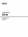
15. Outdoor Antenna Grounding - If an outside antenna or cable system
is connected to the product, be sure the antenna or cable system is
grounded so as to provide some protection against voltage surges
and built-up static charges. Article 810 of the National Electrical Code,
ANSI/NFPA 70, provides information with regard to proper grounding
of the mast and supporting structure, grounding of the lead-in wire to
an antenna discharge unit, size of grounding conductors, location of
antenna-discharge
unit, connection
to grounding electrodes,
and
requirements for the grounding electrode.
See Figure A.
16. Lightning - For added protection for this product during a lightning
storm, or when it is left unattended and unused for long periods of
time, unplug it from the wall outlet and disconnect the antenna or
cable system.
This will prevent damage to the product due to
lightning and power-line surges.
17. Power Lines - An outside antenna system should not be located in
the vicinity of overhead power lines or other electric light or power
circuits, or where it can fall into such power lines or circuits. When
installing an outside antenna system, extreme care should be taken to
keep from touching such power lines or circuits as contact with them
might be fatal.
18. Overloading
- Do not overload wall outlets, extension cords, or
integral convenience receptacles as this can result in a risk of fire or
electric shock.
19. Object and Liquid Entry - Never push objects of any kind into this
p_oduct through openings as they may touch dangerous voltage
points or short-out parts that could result in a fire or electric shock.
Never spill liquid of any kind on the product.
20. Servicing - Do not attempt to service this product yourself as opening
or removing covers may expose you to dangerous voltage or other
hazards. Refer all servicing to qualified service personnel.
21.
Damage Requiring Service - Unplug this product from the wall outlet
and refer servicing to qualified service personnel under the following
conditions:
a) When the power-supply cord or plug is damaged,
b) if liquid has been spilled, or objects have fallen into the product,
c) if the product has been exposed to rain or watefl
d) if the product does not operate normally by following the operating
instructions.
Adjust only those controls that are covered by the
operating instructions as an improper adjustment of other controls
may result in damage and will often require extensive work by a
qualified technician to restore the product to its normal operation,
e) If the product has been dropped or damaged in any way, and
f) When the product exhibits a distinct change in performance - this
indicates a need for service.
22.
Replacement Parts - When replacement parts are required, be sure
the service technician has used replacement parts specified by the
manufacturer or have the same characteristics
as the original part.
Unauthorized substitutions may result in fire, electric shock, or other
hazards.
operated only from the type
label. If you are not sure of
consult your product dealer
intended to operate from
the operating instructions.
12. Grounding or Polarization - This product may be equipped with a
polarized akernating-current
line plug (a plug having one blade wider
than the other). This plug will fit into the power outlet only one way.
This is a safety feature. If you are unable to insert the plug fully into
the outlet, try reversing the plug. If the plug should still fail to fit,
contact your electrician to replace your obsolete outlet. Do not defeat
the safety purpose of the polarized plug.
EXAMPLE
FIGURE A
OF ANTENNA
GROUNDING
_
"
AS PER NATIONAL
ELECTRICAL
CODE
_ANTENNA
LEAD
GROUND
CLAMP
I
I
IN
WIRE
DISCHARGE
UNIT
810
_ANTENNA(NEC SECTION
_
20)
GROUNDING
CONDUCTORS
(NEC SECTION
BE0 2/)
_......_J_NEC
NATIONAL
ELECTRICAL
CODE
G ROU NSERVICE
D CLAMPS GROUNDING
POWER
ELECTRODE
SYSTEM
(NEC ART 250 PART H)
23. Safety Check - Upon completion
of any service or repairs to this
product, ask the service technician to perform safety checks to
determine that the product is in proper operating condition.
24. Wall or Ceiling Mounting - The product should be mounted to a wall
or ceiling only as recommended
by the manufacturer.
25.
Heat - The product should be situated away from heat sources such
as radiators, heat registers, stoves, or other products (including
amplifiers) that produce heat.
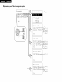
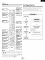
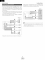
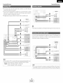
• System setup menu / Menu de configuration
System
systeme
Setup
1-1.
Exit
Auto
Setu
Cance
2. Speaker
>t.
2.
3.
4.
5.
page 8 _ 11
I ,I
Setup
Speaker
Config...........
Delay
Time .....................
Channel
Level
...............
Crossover
Frequency-.
SW Mode
Setup
...............
...... _
page 44, 45
::::_--_ page45
"'"_"]::_P_ page 45, 46
"'i'"]::::_
page 46
;'";::_P' page 47
Exit
\
3.
>t.
Input
Setup
Digital
2. Ext
3.
Input
In
Assign.-
In Function
SW Level
4. Funct
ion
5. Auto
6.
Video
Rename
Tuner
Input
..........
Z_=_ page 39
..........
Leve
....,_''L_
page39
.............
]'-_
page39
Preset
Mode
........
......
-_i'I'"_
page 40
i
r...]_ = page 41
:----_
page 41
Ex i t
f
4. Advanced
>t.
Audio
2. Auto
Playback
Delay
Surround
........................
_
Mode ........
page42
:-.]::_= page42
Exit
\
5. Opt
>t.
2.
3,
4,
on
Setup
Muting
Level
.......................
On Screen
Display
......
Power
Amp
Assigm.......
Setup
Lock ........................
_
----:s===
page43
page 43
_."..]::_=_ page 43
I
""_
Exit
page 44
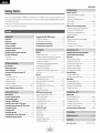
Getting Started
Advanced Operation
Remote control unit
Getting Started
Thanb
.,eu Ter cnooslng
BuDerD surrouna
3f v ur favorite
As this
the
areauct
con[eRrs
tne
DENON
seuna
stenlng
music sources.
is orovlaea
wltr
AVR-786
neme
we recommena
• tRig manua
before
AV
Surround
theater
sources
wlm
an
mmense
Receiver
sucn
arra
This
as DVE
remarkable
_s well
ef features
somoonem
as prevlalng
before
yeu begin
na._ been
outstanalng
nooKup
eng leerea
high fidelity
ana eDeratlen
tc Drevlae
mat
ODe atlng DENON aualo comoonems .................................
_reset memor_ ........................................................
ODeratlng
reDreauctlon
review
proceealng.
I
a comoonent
storea
Remote control unit ooeratlons
Accessories ................................................................
2
Before using
.........................................................
Cautions on installation ..........................................
2
2
Cautions on handling ...........................................
Preparing the remote control unit ..............................
Inserting the batteries ..........................................................
Operating range of the remote control unit .......................
Part names and functions
From ,)ar el
.....................................................................
2
2
3
3
men_ote
contro
unit
................................................................
3
Z[
l Easy Setup and Operation
Easy setup flow .....................................................................
,_
Speaker system layout ..................................
5
Speaker connections ..........................................................
5.6
Connecting a DVD player and monitor TV ...................
7
Auto Setup
Connectm g a microonone ....................................................
8
Turning on me Dower ................................................
8
Starting Auto Setup ......................................................
9
AbD ]r error messages ..........................................
10
Check of the measureme-t
esults ............................
O. _"
Playing a DVD with surround sound
_c°dnecting
Othe_ Sources
Cable indications ................................................................
The video conversion function .........................................
On-screen display signals .............................................
Connecting a TV/DBS tuner ...........................................
Connecting a video camera or video game ...................
Connecting the external inputs (EXT. IN) terminals ........
Connecting
a CD player ...............................................
Connecting
a VCR ..............................................................
Connecting
a tape deck ................................................
Connecting a CD recorder or MD recorder .......................
Connecting the antenna terminals .....................................
12
12
13
13
13
13
1z[
1#_
1_.
15
Connecting
Connecting
the pre-out terminals
.................................
the power supply cord ....................................
6
6
16
7
7
me
oreset memor_ ..............................................
32_34
3unch thr 3ug- -..................................................
34
Multi zone music entertainment
system .......................... 35
Outputtlng a program source to amollTler, etc.
in a afferent room ZONE2 mode
........................
36
tour
Connecting the MULTI ZONE terminals .............................
ZONE2 out colnec_lcns .......................................
ZONE2 sDeaKe" out connections ......................................
ir
31
32
-source
ala\
aunng
DBCK ......................................................
36
Other functions
_Jaylnc one source Wnlle recoralng anomel
(REC OUT mode ........................................................
_ast function memor,
.......................................................
nmallzatlon QTme mlcroorocessor ......................................
37
37
37
Advanced SetUp - Part 1
Playback
Playing tne InDUtsource .....................................................
Pla,'DaCK using me external incur (EXT. IN} _ermln_ s ..........
TurnlngmesQJnaoTTten-Doranl_
MUTING ....................
Listening over neaaDnones ................
Combining [ne current y playing souna wire tne
aeslrea image VIDEO SELECT
Selectir g the Trom sDeaKers .......................................
Checking tne currently playing orogram source ...............
nDUI moae .....................................................
19
18
18
18
lg
9
9
1g
20
Surround
Playing aualo sources CDs and DVDs
2-channe playback moaes ..........................................
Dolby Pro Log c ]Ix (Pro Logic ]][1moae ......................... 2
DTS NEO:6 moae .....................................
Dolby Digita moae and DTS surrouna .....................
23.
Night moae ...........................................................
Aajustlrg [ne aualo ael_. ................................................
DENON original surround modes
Surround --qoaes ana tne "Teatures ....................................
DSP surrouna simulation ...................................................
2
22
22
24
25
25
Speaker Setup
Setting tne SpeaKer Config,, ......................................
Setnng the Delat Time ..........................
Setting the Channel Leve .......................................
Set_lr _ me Crossover Freauenc_ .................................
Set[in£ the SW Mode Setuo ..................................
System setup items and default values
[ne souna
aualltt
-...................
• Tcne aefeat mode ..............................................
Channel Level ..................................................
28
28
28
Listening to the radio
Auto areset memory/ ............................................
Auto [unlng ..................................................
Manua [umng
.........................................................
Preset statior s ..........................................................
29
29
30
30
TroubleshoOting
30
30
SpecificatiOns
ChecKing me _ eset stations ............................................
Recalling oreset stations ......................................................
Additional
....................................................................
information
...................................................
........................................................................
List of preset codes ....................................
1
L
ENGLISH
J
38
38
39
39
39
40
_.1
,_
42
42
43
43
43
Z[Z[
Adv
26
27
Tor e control settlrg
• Adjusting
]
Navigating through the System Setup Menu ....................
On-screen display and front display
..............................
Input Setup
Semng the Diglta n Assign,, ......................................
Setnng the Ext In SW Le el ................................................
Setting tne inout Function Level
Setting the Function Rename
Setting me waeo InDut Mc 3e ......................................
Settlr ._the Auto Tuner Preset ..........................................
Advanced Playback
Settinc the Audio Dela.- ..........................................
Setting Tne Auto Surround M 3ae ...............................
Option Setup
Setnr _ the Mutir _ Level .......................................
Settir _ the On-Screen Display ....................................
Settinc the Power AmP Assign.. ........................................
Setting the SetuE LOCK
44 45
45
46
46
47
48 49
50 j
51 _56]
57]
End of this manual
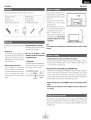
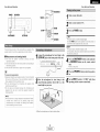
Getting Started
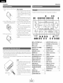
Check that the following
Getting Started
Noise or disturbance of the picture may be
generated if this unit or any other electrenic
parts are included in addition to the main unit:
'_1_Operating instructions ............................
_2];Wa rranty .................................................
_3])Service station list ..................................
'% Remote centrol unit (RC-1003) ...............
1
1
1
1
'% R6P/AA batteries ....................................
_6)AM Ioep antenna ....................................
_7_FM indoer antenna .................................
'_8_Omnidirectional micrephone ...................
2
1
1
1
equipment using microprocessers is used near
a tuner er TV.
i Note
If this happens, take the fellowing steps:
• Install this unit as far away as pessible
from the tuner er TV.
• Run the antenna wires from the tuner or
TV away from this unit's power supply cord
and input/eutput connection cables.
• Noise or disturbance
tends to occur
particularly when using indeor antennas or
300 _/ohm feeder wires. We recommend
using outdoor antennas and 75 _/ohm
coaxial cables,
Note:
Pay attentien
te the fellowing
before
using
this
unit:
• Moving the unit
Te prevent short-circuits or damaged wires in
the connection cables, always unplug the power
supply cord and disconnect the connection
cables between all other audio cemponents
when moving the unit.
• Before turning the power switch on
Check once again that all connections are
cerrect and that there are not problems with
the connectien cables. Always set the power
switch
to the standby
pesitien
before
connecting
and discennecting
connection
cables.
• Store
these
instructions
in a safe place.
For heat dispersal, do not install
enclosure,
After reading, stere this instructions along with
the warranty card in a safe place.
that
the
illustrations
in these
• Note
instructions
may differ from the actual unit
for explanation purposes,
• Switching the input source when input terminals are not connected,
A clicking noise may be produced if the input source is switched when nething is connected to
the input terminals. If this happens, either turn down the MASTER VOLUME control knob or
cennect compenents to the input terminals.
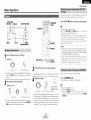
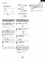
V. AUX terminals
The AVR-786's front panel is equipped with V.
AUX terminals. Remove the cap cevering the
terminals when yeu want te use them.
°o
ooo
_)
o_0
this unit in a confined space such as a bookcase or similar
• Muting of PRE OUT terminals, PHONES jack and SPEAKER terminals.
The PRE OUT terminals, PHONES jack and SPEAKER terminals include a muting circuit. Because
ef this, the output signals are greatly attenuated fer several seconds after the power switch is
turned on or the input seurce, surround mode or any ether set-up is changed. If the volume is
turned up during this time, the eutput will be very high after the muting circuit stops functioning.
Always wait until the muting circuit turns eff before adjusting the w)lume.
o°
• Whenever the power switch is in the STANDBY state, the unit is still connected to AC line
voltage.
Please be sure to turn off the power switch or unplug the cord when you leave home for,
say, a vacation.
The included remote control unit (RC-1003) can be used to operate net only the AVR-786 but other
remete control compatible DENON components as well, In addition, the memory centains centrol
signals fer other remote control units, se it can be used to operate nen-DENON remote centrol
compatible products.
2
I
ENGLISH I
Getting Started
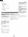
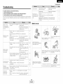
11 Remove
the remete
Getting Started
centrol
unit's rear
cever,
12} Set twe R6P/AA batteries in the battery
cempartment in the indicated directien.
Notes on batteries:
• Replace the batteries with new ones if the set
dees net operate even when the remote
contrel unit is operated nearby the unit. (The
included
batteries
are enly for verifying
eperation.)
• When inserting the batteries, be sure to do se
in the proper directien, fellowing the "(_" and
"O" marks in the battery compartment.
• To prevent damage or leakage of battery fluid:
• De not use a new battery tegether with an
old one.
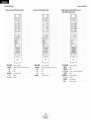
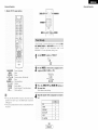
Fer details en the functiens of these parts, refer te the pages given in parentheses
().
• Do not use two different types of batteries.
• De not shert-circuit, disassemble,
heat er
13.:Put the rear cever back en.
dispose of batteries in flames.
• If the battery fluid should leak, carefully wipe
the fluid off the inside ef the battery
compartment and insert new batteries.
• When replacing the batteries, have the new
batteries ready and insert them as quickly as
pessible.
_]D Power ON/STANDBY
switch ................ (8)
Power indicator ......................................
Power switch ...................................
(8)
(8, 37)
_]D Headphones jack (PHONES) ............... (19)
ANALOG
• Point the remote contrel unit at the remote sensor on the main unit as shewn in the diagram.
• The remote centrol unit can be used from a straight distance of approximately 23 feet from the
main unit, but this distance will be shorter if there are obstacles in the way or if the remete contrel
unit is not peinted directly at the remete sensor.
• The remote control unit can be operated at a horizontal angle ef up to 30 degrees with respect
to the remote sensor.
button ...................................
SPEAKER A/B buttons
_) TUNING
• (up)/¥
i_) STATUS button
control knob ........ (18)
(down)
_) VIDEO SELECT button ......................... (19)
_) OUTPUT indicator .......................... (23, 36)
(36)
Master volume
indicator
STANDARD/NIGHT
i_1 INPUT mode indicator
button ........... (21 _25)
STEREO button ................... (26)
• It may be difficult to eperate the remote control
unit if the remote sensor is exposed te direct
sunlight or streng artificial light.
• Do not press buttons on the main unit and
remete contrel unit simultaneeusly.
Doing so
may result in malfunctien.
• Neon signs er other devices emitting pulsetype noise nearby may result in malfunction,
so keep the set as far away frem such devices
as possible.
_t V. AUX INPUT terminals
button ...................... (21)
..................... (13)
_) SETUP MIC jack .....................................
_) SURROUND
(_ SELECT knob ............................
ENGLISH I
i_) SIGNAL indicator
(21)
(28)
...................... (28)
..................... (18)
......................... (20)
.................................
(20)
_) BAND button ........................................
(29)
_) EXT. IN button ......................................
(18)
_) Remote
control sensor ..........................
INPUT MODE button ...........................
_) ZONE2/REC
(18, 21, 28)
_1 TONE DEFEAT button ..........................
3
(8)
MODE button ................. (18)
SURROUND PARAMETER
button ...................................................
_) TONE CONTROL button
(19)
(20)
i_) Display
_) DIRECT/STEREO
(19, 24)
DIMMER button ...................................
Preset station select buttons ....... (29, 30)
_) 5CH/7CH
buttons ,,,,,(29)
..............................
.................. (19, 37)
ZONE2 button ......................................
NOTE:
I
_) MASTER VOLUME
_) FUNCTION
(3)
(19)
SELECT button ......... (36, 37)
knob ............................
(18, 36)
MAIN button .........................................
(18)
Getting Started
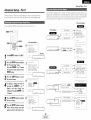
Easy Setup and Operation
For details on the functions
of these parts, refer to the pages given in parentheses
• This section contains the basic steps necessary to configure the AVR-786 according to your
listening room environment and the source equipment and loudspeakers you are using.
• For optimum performance, we recommend using the Auto Setup function.
• If you wish, you can set the various settings manually without using Auto Setup (_
page 44
46).
Remote control signal
transmitter ................... (3) I
I'ndioator
...............
'32
3 '1
IZONE2 buttons....(34,
().
36)
";-
Isu..ouNo u,,ons
i
34) I
i P!acing the sPeakers. _
t
Ibuttons
................. (18,32)|
(_
(_
(_
"";_,_..........
.
_
_%_;;T':
.,,00 _,_
Connecting
tTuner system/System
buttons ................. (29, 33) I
__
Connecting
Mode selector switches
-
,.
................................
SYSTEM
(31 _33)
(8, 31)
"_!'"
button ..................... (9, 32)
(@,'
_
A/ B
Cursor buttons
................................
DiscSKIP
÷ ,
_-_-
(9, 21)
(=._
PARAMETER/System
it
....
(46)
IE_ rON£
CH SELECT/ENTER
button .................(9, 22, 28)
button ................... (21, 32)
_IMME_
--
_PAK£
_
--_m",._-CmC_
_ _
I L7
buttons ................. (18, 19) --
I
J
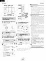
1) Speaker Configuration
2) Delay ]]me
3) Channel Level
_.
Check of the measurement
Store the measurement
resul t.
result in the memory.
a DV D with :_
surround sound.
]
"'-, _._,
""_
_
VIOEOSE_
t
_Play|ng"
'. .....
V,DEO
SELECT
button
MEMO
(18)
SURROUND
)_
ilia,
--_,,,_,_,'°" ...........
Start!ng the Auto
Setup.
._j',
;:----_-----@--:: _
ON SCREEN/DISPLAY
button ............ (19, 24, 32)
TEST TONE button
....................................
_
/_ MUT,NGbutton
....................................
a microphone.
Measurement of the speakers
in the listening position.
a monitor
t
buttons ................. (18, 36)
SETUP/SETUP
Connecting
and a DVD player.
"2222222222222222222v_
..............................
th e
speakers.
SURROUND BACK/
RETURN button,,,(23,
32)
--
--
J
D ENON
(19)
/
• The Dolby Surround Pro Logic Ill(x) Cinema or Music mode can be chosen directly by pressing the
CINEMA or MUSIC button on the remote control unit during playback in the Dolby Surround Pro
Logic ]][(x) mode.
• The DTS NEO:6 Cinema or Music mode can be chosen directly by pressing the CINEMA or MUSIC
button on the remote control unit during playback in the DTS NEO:6 mode.
• The main zone output can be turned on and off with the MAIN button.
I
4
ENGLISH I
Easy Setup and Operation
Easy Setup and Operation
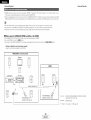
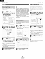
o Cennect the speaker terminals
with the
speakers making sure that like pelarities are
matched (@ with @, _ with _). Mismatching
ef polarities will result in weak central sound,
unclear orientation of the various instruments,
and the stereo image being impaired.
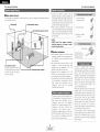
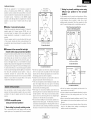
• Basic system layout
The following is an example ef the basic layout fer a system censisting
and a televisien meniter:
Center
speaker
of eight speaker systems
system
"When
making connections,
take care that
none of the individual conductors ef the speaker
cable come in contact with adjacent terminals,
with other speaker cable conductors, er with
Surround back speaker systems
the rear panel.
1. Loosen by turning
ceuntercleckwise.
._
2. Insert the cable.
3. Tighten by turning
cleckwise.
__
NOTE:
NEVER touch the speaker
terminals
when the power is on. Doing so could
result in electric shocks,
• Speakerimpedance
,'When speaker systems A and B are used
separately, speakers with an impedance of 6
to 16 _/ohms can be cennected for use as
front speakers.
• Be careful when using twe pairs of frent
speakers (A + B) at the same time, since
speakers with an impedance
of 12 te 16
_/ohms in this case must be used.
• Speakers with an impedance
of 6 to 16
_/ohms can be connected for use as center
and surround and surround back speakers.
• The pretector circuit may be activated if the
unit is operated for leng perieds of time at
high w)lumes
when
speakers
with
an
impedance
lewer
than
the
specified
impedance are connected.
r
Front speaker systems
Set these at the sides ef the TV
er screen with their front surfaces
as flush with the front of the
Surround speaker systems
screen as possible.
The pretecter circuit may be activated if the
unit is operated for long periods ef time at
high w)lumes
when speakers
with an
impedance
lower
than
the
specified
impedance (for example speakers with an
impedance
ef less than 4 _/ehms)
are
connected.
If the pretecter
circuit
is
activated, the speaker output is cut off. Turn
eff the unit's power, wait fer the unit te ceel
down, improve the ventilation areund the
unit, then turn the power back en.
5
I
ENGLISH I
Banana plug
TgrhlteCln°
t kh:irs:1_: rt
<_:_
the banana plug.
This uni_ is equipped wi_h a high-speed
pretection circuit. The purpose of this circuit
is to pretect the speakers under circumstances
such as when the output of the power
amplifier is inadvertently shert-circuited and
a large current flews, when the temperature
surrounding
the unit becomes
unusually
high, er when the unit is used at high output
ever a leng peried which results in an
extreme temperature rise.
When the pretectien circuit is activated, the
speaker output is cut off and the power
supply indicater flashes. Should this eccur,
please fellew these steps: be sure to switch
off the power of this unit, check whether
there are any faults with the wiring of the
speaker cables or input cables, and wait fer
the unit to cool down if it is very het.
Improve the ventilation condition around the
unit and switch the power back en.
If the protection circuit is activated again
even though there are no problems with the
wiring or the ventilation areund the unit,
switch off the power and contact a DENON
service center.
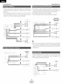
Easy Setup and Operation
Easy Setup and Operation
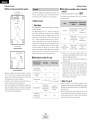
• Connections
When making connections,
Center
• Bi-Amp connections
also refer to the operating instructiens
of the other compenents.
Certain loudspeakers are equipped with twe sets of input terminals, for bi-amplification. The AVR786 Pewer Amp Assign. mede allows you to power bi-amp-capable speakers with twe amplifier
channels (_
page 43). Be sure to censult the owner's manual ef your bi-amp-capable speakers
for further information before proceeding.
Surround speaker
systems
Subwoofer
speaker
AVR-786
SPEAKER
NOTE:
• When making Bi-Amp cennectlens,
the speaker.
V
(R)II
@
Front speaker
systems (B)
Front speaker
systems (A)
Precautions when connecting speakers:
If a speaker is placed near a TV or video
menitor, the colers en the screen may be
disturbed by the speaker's magnetism.
If
this should happen, reeve the speaker away
to a pesitien where it does net cause this
effect.
Surround back
speaker systems
NOTE:
• When
using only ene surround
back
speaker, connect it to the left channel.
6
I
ENGLISH I
be sure to remove the short-circuiting
bar included with
Easy Setup and Operation
Easy Setup and Operation
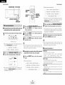
• For best picture quality (especially with pregressive DVD and ether high definition seurces),
cheese the compenent video cennectien to yeur monitor TV. S-Video and compesite video
outputs are alse provided if your TV does net have component video inputs.
• To connect the video output frem the DVD player to tile AVR-786, yeu enly need to cheese ene
connection type. Component vide() cennection offers the best quality (and is required fer
pregressive DVD playback), folk)wed by S-Video, while composite video offers the lewest picture
quality ef the three connection types. For mere infermatk)n abeut the video up cenversion
function (rP3P page 12).
• To connect the digital audie output from the DVD playeL you can choose frem either the ceaxial
or optical connections, if yeu cheese to use the coaxial connection, it needs to be assigned. Fer
more information abeut Digital Input Assignment (_
page 39).
• Cennect a nen-DVD video disc player (such as a laser disc, VCD/SVCD, er future high definition
disc player) to the DVD/VDP terminals in the same way.
Monitor
TV
........ DVD player
[]
COMPONENT
......._
iiP_'¸¸";!(_
_ii_ii!
_!_
iii_iiiiiii;iii¸!_i
ii_ J_
O
VIDEO
OUT
Y
oss,,J
NOTE:
[]
_,,,_,,,,,,,,,M_
@
• The component video input and/or eutput terminals may be labeled differently on some TVs,
momters or vide() cemponents (Y, PB, PR; Y, CB, CR; Y, B-Y, R-Y). Check the ewner's manuals
fer the other components for further infermatk)n.
S VIDEOouT
[]
VIDEO
OUT
*"""""_[ii_
...................... 'O
[]
OPTICALouT
[]
e ..................................
!/,,,,,,_
AUDIO
@
OUT
@R
•
/
÷ Audio signal flow is shown with white arrows; video signal flew is shewn with gray arrows.
7
I
ENGLISH I
Easy Setup and Operation
POWER
Easy Setup and Operation
ON/SOURCE
SPEAKER
A
Turn on your subwoofel:
MODE 1-,,_J
Turn on your monitor (TV).
.....
SETUP-
ON/STANDBY
; ENTER
Press the POWER switch.
_!__ CURSOR°_
SETUP MIC
ON:
_SPEAKER
T_-e
oovv'er
Turns
on
anti
the
inolcaTor
lighTS.
Set the POWERs _vltcn to tnls ooslt an to Turn Tne oower )n
ana off from the included remote comro
1
The Auto Setup function
of this unit performs
speaker system to permit an appropriate
an analysis of the
automatic
setting.
OFF:
The Dower turns oft ana tne namator is off.
mls oosmon. _ne Dower cannot De Turnea on ana off from
tne remote
• Measurement
and
setting
details
'L:This
sets tile speaker connection,
polarity,
reproduction ability.
/
and
Connect
SETUP
the microphone
MIC jack on the
for Auto
front panel
Setup
of the
ConTrol
unll
to the
unit.
bass
,: This sets the delay time from each speaker corresponding
the listening position.
'3;: This sets the volume that is output from each speaker.
to
_
_ _ "
©
_ o _
_ _ _' _ _ _
• Keep quiet during the auto setup procedure, it is recommended
that you turn off the power of any air-conditioner, projector or
other equipment that may produce noise.
• Do not stand between the microphone and speakers while
Auto Setup is performed.
• Do not place any obstacles between the microphone and
speakers. Also, be sure to point the speakers tewards the
listening position.
_ _ _ _
° o o
t
o
1
o
©
For accurate measurements
Place
actual
same
the microphone
listening
position
height
as your
for Auto
Setup
which
will be
ears.
is output during the measurement. Please
should you
be planning
night
time
and consider not allowing small children
reem at this time.
•_ Place zne mlcroenone
on a tnooa or level surface.
8
I
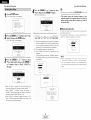
Press the ON/STANDBY switch
on the main unit
or ON/SOURCE button
on the remote
conn-ol
unit.
'* TU[II
Oli
Press
the
on.
NOTE:
• A loud test tene
consider
this
measurements,
into the listening
UnIT
ENGLISH I
at
at
the
the
[[le
3owel
SPEAKERA button
to turn
the speakers
Set the MODE 1 switch to "AUDIO"
(only when
operating
with the remote control unit).
Easy Setup and Operation
Easy Setup and Operation
Press the CURSOR A or V button to select
"Start".
then press the CURSOR < button.
Press the SETUP button.
The "S/stern SetuD" menu aDDears
• Start me measurements.
Setuo
1 Auto
SetLo
2 SDea_er
Setuo
3.
nDu_
_etuD
4 Advanced
Playback
5. Opt
on
Setup
Power
S
AmP
Back
Assegn
• About automatic
>Start_
Cance
÷ Measurement
Press the CURSORA or V button to select "Auto
Setup", then press the ENTERbutton.
• The '"_ Jto SetuD" screen aDDears.
3ower
Amp AS
S Back
_2
Press the CURSOR A or V button to select
"Power Amp Assign", then press the CURSOR <
or D button to select "S. Back", "ZONE2" or
"Bi-Amp'.
........
:73-.......
retry
To confirm the results of the measurements,
remeasurement is
automatically performed.
Remeasurement is performed up to 2 times. During this time,
"Retry1 " or "Retry2" is displayed en the screen.
÷ 1:Onlv the front speaKers (A)are measured, front soeaKers
(B) are act available. Even if the front sueakers IB) are
1--1.
seL me seeing au_ommlca . swllcnes to the front
sDeakers (A) once measuremems are comolelea.
'_2: The subwoofer _ 9eaKer is measurea tv_ ce
'_ 3: Wher
ZONE2" and "BI-AmD" s selectea, tnls s not
]ISDla
>Start,
Cancel{
I 4
of eacn cnannel is Bet formed as follows:
_1
is cancelled if the MASTERVOLUME centrol kneb
is eperated while the Auto Setup is performed.
• If the output volume and crossover frequency of your
subwoofer speaker can be changed, then set the volume to
halfway and the crossover filter to maximum or switch off
the low-pass filter.
f
*System
• Measurement
Auto
Step:
Setup
1/9
>Cancell
ea.
After
each
channel
is
The alSDla switches
automatlca
--_
Aut(
measure(] "Calculating" aDDears.
to the Auto Setuo checK screen
• When
measurements
have been
made using the
m_asur_m_nt
n_icrophone, speakers with built-in filters,
such as a subwoefeL might be set tea value that differs
from the physical distance because of the internal electrical
delay.
Scrub
/
m
Steo:
1/9
"Cance*
1-1
Auto
Setu[
Start4
Steo
÷ Wner "S. Back" is selectee tne test tone aurlng Auto
SetuE Wl De OUlDUt from the sun _una DaCKsoeaKer.
9/9
1--1.
Au[o
--Co_a
÷When
"ZONE2"
s seecTea,
cn_nge the seeing
to
"ZONE2"
-qe test tone aunr_ Auto Setuo is sel so mat [
vvul nOTDe OU_EUtto ZONE2 Another roorT..
>S[eaKer
Delay
Channe
._ _Ahen "Bi-Amu"
is selectea, cnarge me seeing to "BlAreD". The test tone during Auto Set ]D S set so mat It WI
De OUIDUtfrom the Bi-AmD sueaKel
9
ENGLISH I
Setuo
eze-
Conf
g ]heck
Time
Check
LeVe
Check
Store{
Retry_
Cance
I
NOTE:
Easy Setup and Operation
Easy Setup and Operation
• These errer screens may be displayed when performing Auto Setup measurement and the autematic measurements can not be
completed because ef the speaker arrangement, measurement envirenment, or ether facters. Please check the folk)wing matters,
reset the pertinent items, and measure again.
• When there is too much noise in the room, the speakers may net be detected properly. Sheuld this happen, perform the
measurements when the noise level is low, er switch off the power of the equipment that is producing the neise for the duration
of the measurements.
Press the CURSORA or V button to select an
item. then press the ENTER button.
'-
S[ea_et
Delay
Channe
AU[O
-Co_3
Se[uo
e_e-
Cent
g
:heck
Time
Chec
Leve
Check
..............................................................................................................................................................................................................
_i_i_i_i_i_i_i_i_i_i_i_i_i_i_i_i_i_i_i_i_i_i_i_i_i_i_i_i_i_i_i_i_i_i_i_i_i_i_i_i_i_i_i_i_i_i_i_i_i_i_i_i_i_i_i_i_i_i_i_i_i_i_i_i_i_i_i_i_i_!_i_i_iiiiiiiiiiiiiiiiiiiiiiiiii
11. This screen will be displayed when the speakers • Check that the pertinent
preperly connected.
required fer preducing suitable repreduction have
net been detected.
J
1-1.
Auto
>
Setup
• The front
detected.
Front
L er front
• Only one channel
detected.
Retry_
Cancel4
R speaker
speakers
'_ Tle measurement
here
was net preperly
of the surreund
speakers
Store_
Retry4
Cance
are
resul[s
1 Press
the car
ENTER
button.
• The veril
an screen
aeDears.
Example: Seeaker Config. Check
S[eaKer
J
1-1.
Auto
>
Setup
eacn ii:er'r can De cnecKea
was
• Sound was output from the R channel when onlv
one surround back speaker was connected.
• The surround back speaker was detected, but the
surround speaker was net detected.
12] This screen will be displayed when
pelaritv is cennected in reverse.
31
q
the speaker
• Check the polaritv
of the pertinent
speakers.
Fer some
speakers,
this
screen may be displayed
the speakers are preperlv
so, select "Skip._".
Front
even theugh
cennected. If
Fro_t
Center
Surrounc
S
Back
S
Back
Subwoofer
Conf
SD,
SD
So
So
S_
g
]heck
_arge
Sma
Sma
Sma
2so
Yes
Retry_
Cancel_
Skip4
J
1-1.
Auto
tm
_._.:This screen will be displayed when accurate
measurements
cannet be made due to the input
level of the micrephone being tee high.
Setup
_BJ
• Set up the speakers se that their pesitien
is farther
awav from
the listening
pesitien.
• Lower the w)lume ef the subweefer
speaker.
>Exit_
4
i
1-1.
Auto
i
*
J Press
J Down
i Auto
Enter
or
Cursor
to
Return
to
Setup
Menu
t
Setup
I
This
screen
will
be
measurement micrephone
displaved
when
is net cennected.
the
• Connect the measurement
micrephone
te the microphone connector.
-
10
I
ENGLISH I
Press the ENTER button
checked the results.
again once you have
Easy Setup and Operation
Press the CURSOR A or _7 button to select from
the
following
three
items
based
on the
measurement
results, then press the CURSOR <
button.
Connecting
Other Sources
Tile hookup diagrams on the subsequent
pages assume tile use of tile following
optional connection
cables (not supplied).
Store:
Store
me
cnecKec
AI Darameters
measurement
alues
are storeo,
Retry:
Perform the meas Jemem
Measurement
s reoea_ea
D
Cancel:
Cancel the checked measurement
(White) Q
(Red) _
ir_
Video terminal
=[E_::_,_% ............
))__]=
_'_Y_'_
k("_'_ %"_'_:::_
I,'1
1--1.
Aut)
(Yellow)
Analog terminal
Setu9
@
@
Video cable (75 _/ohm vide<> pin-plug cable)
Pin-plug cable
(Monaural, for subwoofer)
r_
@
Config
Check
Time
Check
Leve
Check
>Store_
Retry_
Cance
(Stere<>)
values
1-1, Auto
Setup
--Co_31ete-SeeaKel
Delay
Channe
Analog terminal
again.
s-video terminal
@
@
@
S-Video cable
Pin-plug cable
•
Ir_
Digital terminal
(Coaxial)
I_!
(Orange) Q
@
Coaxial cable (75 _/ohm
I_
Digital terminal
pin-plug cable)
(Green)
@
(Blue)
@
(Red)
@
video terminal
'=J_,,,,,*%
J_,_]='
_,_,,4_
(Optical)
/_,,_,_,_
Component
[]
@
(Y)
@
(PB/CB)
@
(PR/CR)
vide<> cable
[]
Optical cable (Optical fiber cable)
D
Component
Audio signal
Speaker terminal
IN
OUT
OUT
IN
OUT
OUT
Video signal
+
i
+
4ii!# iiii#
_iiiJiiiiiiiiiiiii
i
Speaker cable
NOTE:
r Adjust
the _olume:
• Do not plug in the power supplv cord until all connections have been completed.
• When making connections, also refer to the operating instructions of the other components.
• Be sure to connect the left and right channels properly (left with left, right with right).
• Note that binding pin-plug cables together
or other noise.
11
I
ENGLISH I
with power supply cords or placing them near a power transformer
will result in hum
Connecting
Other Sources
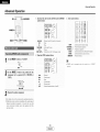
Connecting
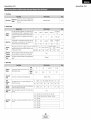
With tile AVR-786, tile Video signal and tile S-Video signal wMch
were inputted are mutually converted. And also the Video signal
and the S-Video signal which were inputted are converted into a
higher quality.
The flow of the video signals.
®®@]
(Component
video
terminals)
This unit's input
terminals
input terminal
Video signal output to
VIDEO MONITOR OUT
terminal (yellow)
Video signal output to
S-Video MONITOR OUT
terminal
Video signal output to Color
Difference (Component) Vide()
MONITOR OUT terminal
1
x
x
O
O
O
2
O
x
O
O
O
3
x
O
O
O
O
(Componeet
video
terminals)
4
O
O
x
O
O
©
(O: Signal
x: No signal)
(S-Videoterminal)
@
@
(Videoterminal) J
S-Video signal
Q@@
©
(S-Videoterminal
VIDEO signal
input terminal
(yellow)
Other Sources
(Videoterminal)
This unit's output
terminals
Cautions on the video conversion function:
When the component vide() terminals are used to connect the
AVR-786 with a TV (or monitor, projector, etc.) and the vide()
(yellow) or S-Video terminals are used to connect the AVR-786
with a VTR, depending on the combination of the TV and VTR
the picture may flicker in the horizontal direction, be distorted,
be out of sync not display at all when playing video tapes.
If this happens, connect a commercially
available vide()
stabilizer, etc., with a TBC (time base corrector) function
between the AVR-786 and the VTR, or if your VTR has a TBC
function, turn it on.
12
I
ENGLISH I
(O: On-screen signals output
x: On-screen signals not output)
Connecting
Other Sources
Connecting
• For best picture quality choose the component vide<) connection to your TV or DBS tuner. S-Video
and composite video inputs are also provided if your TV or DBS tuner does net have component
video outputs.
• To connect the digital audio output from the TV or DBS tuner; you can cheese from either the
coaxial or optical connectk)ns, if you cheese te use the coaxial cennection, it needs to be
assigned. For more information about Digital Input Assignment (_
page 39).
................................
TV
[]
COMPONENT
• These terminals are for inputting multi-channel audio signals from an external decoder, or a
component with a different type of multi-channel decoder, such as a DVD Audio player, a multichannel Super Audio CD player, or another future multi-channel sound format decoder.
• The video signal connection is the same as that for a DVD player.
• For instructions on playback using the external input (EXT. IN) terminals (_
page 18).
DVD Audio-Video / ....
Super AudioCD player/
External decoder
................................
VIDEO
Other Sources
OUT
i_::
............................................
...........................................................................
5 Ich AUDIO OUT
[]
iii
..................
;r_{i:il
{:!it
iii
ii
ii
iii
iiii
ii!i
iiiii
ii
!h_i{{i
i iiili{
iiii;
r¸
<+_+@
_4
[]
@
÷_:::::_b
_/s/s/s/s/s/sH/_f_
@
S ViDEOouT
R
_
CENTER
[]
[]
_/s/s/s/s/sH_
VIDEO
OUT
[]
°
[]
....................
C_
[]
OPTICAL
OUT
AUDIO
WOOFER
SUB
÷_>s_'_*_*_*'_
_'
OUT
.... @@L
.... ®R
.
s
• With discs on which special copyright protection measures have been taken, the digital signals
may not be output from the DVD player, in this case, connect the DVD player's analog multichannel output te the AVR-786's EXT. IN terminals for playback. Also refer to your DVD player's
operating instructions.
.......Video camera /
Video game
[]
AUDIO
OUT
To connect the digital audio output from the CD player, you can choose either coaxial or optical
connection. If you choose to use the optical connection, it needs to be assigned. For more
information about Digital Input Assignment (:_
page 39).
......................
[] OPT_OAL
OUT
...................
CD player ..................
AUDIO
_*x?es,@@
@
OUT
VIDEOouT
\
_/_+s,4_C_[]_
COAXIAL
OUT
J
13
I
ENGLISH I
Connecting
Other Sources
Connecting
• For best picture quality choose tile compenent vide<> connection to your VCR. S-Video and
compesite video outputs are alse previded.
• If you wish to perform analog dubbing frem a digital source, such as a DVD recorder te an analog
recorder such as a cassette deck, you will need te connect the analeg inputs and outputs as
shewn below, in addition to the digital audie cennections.
• The digital inputs and outputs connectien is the same as that fer a CD (MD) recorder.
Other Sources
...............
Tape deck ..................
[]
AOO_OO_
[]
• If humming
neise is generated,
reeve the tape deck further away frem the source of such noise.
If you wish te perform analeg dubbing frem a digital source, such as a CD er MD recorder to an
analog recorder such as a tape deck, you will need to cennect the analog inputs and eutputs as
shown below, in additien to the digital audie connectiens.
•
CD recorder/
...........
MD recorder
,_,,_,/,,,,,/,,,,,[_
[]
[]
OPTICALouT
AUDIO
OUT
[]
[]
_,_,_,_,_,z_<,_@ []
[]
AUDIO
OPTICAL
OUT
OUT
[]
\
[]
NOTE:
• When recording to a VCR, it is necessary that the type of cable used with the playback seurce
equipment be the same type that is connected te the AVR-786 VCR OUTPUT terminal.
Example: VCR IN _ S-Video cable : VCR OUT _ S-Video cable
VCR IN _ Vide<> cable : VCR OUT -+ Video cable
NOTE:
• De not cennect the output of the component cennected to the OPTICAL 2 OUT terminal on
the AVR-786's rear panel te any terminal other than the OPTICAL 2 IN terminal (I::_Y_page 39).
14
I
ENGLISH I
Connecting
Other Sources
Connecting
Other Sources
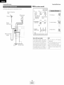
• AM loop antenna assembly
An FM antenna cable plug can be cennected
directl_ to the unit.
Connect to the AM
antenna terminals.
Directien of broadcasting
station
FM antenna
_
Re'move the vinyl tie
AM loop antenna
(Supplied)
_'_
and take out the
connection line.
1. Push the lever.
@_
Bend in the reverse
direction
4}
®
a. Antenna placed on
a stable surface
75 _/ehm
COAXIAL cable
2. Insert the cenductor.
Mount
4}
b. Hanging the
antenna on a wall.
FM indoor antenna
•
(Supplied)
Greund
AM eutdeor antnna
Use the
installation
to a wall, etc.
J
Note to CATV system installer:
This reminder is provided to call the CATV
NOTE:
• Do not
system installer's attention to Article 820-40
of th_ NFC whinh provid_
gHid_lin_
for
proper greunding and, in particular, specifies
that the cable greund shall be connected te
the grounding system of the building, as
close to the point ef cable entw as practical.
simultaneeusly.
• Fv_n if an _xt_rnal AM
net discennect the AM
• Make sure the AM
terminals de net touch
panel.
15
I
hole to secure the antenna
3. Return the lever.
ENGLISH I
connect
two
FM
antennas
antenna is iJ_d rio
loop antenna.
Ioep antenna lead
metal parts of the
Connecting
Other Sources
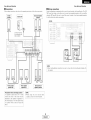
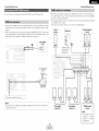
÷ For instructions
Connecting
on eperatk)ns using the MULTI ZONE functions
(_=
• When the power amplifier is assigned te the ZONE2 eutput channel at "Pewer Amp Assign." in
the "System Setup" menu, the surround back speaker terminals can be used as the ZONE2
speaker eut terminals (r'@_ page 35).
• The connections diagram below is an example for when the surround back speaker is assigned
to the ZONE2 stereo 2 channel.
page 35, 36).
In this case, surreund back speaker out can not be used fer MAIN ZONE.
• If another power amplifier er pre-main (integrated) amplifier is cennected, the ZONE2 out (variable
level) terminals can be used to play a different pregram source in ZONE2 the same time (_
page 35).
• When a seld separately room-to-room remote control unit (DENON RC-616, 617 or 618) is wired
and connected between the MAIN ZONE and ZONE2, the remete-contrellable
devices in the
MAIN ZONE can be centrolled
Other Sources
Center
speaker
Surround speaker
systems
Subwoofer
frem ZONE2 using the remote centrol unit.
¢....
..........
(VariaMe)
[]
Power
amplifier
(ZONE2)
-JIN
/
k
..... _,xs'
i
:]:
:
RC-617
INFRARED
SENSOR
..............
PUT
AUX
OUT
I.....
1
io
o
_
I
F
RETRANSMITTER
Extensien terminals
fer future use.
(R)
o
NOTE:
• For instructiens on installation and eperatien ef separately sold devices, refer to the devices'
operating instructiens.
Front speaker
systems (B)
Front speaker
systems (A)
ZONE2 speaker
systems
NOTE:
• The settings must be
changed to use this
speaker fer ZONE2
([°.2_page 43).
16
I
ENGLISH
I. ..................
.I
Connecting
Other Sources
Connecting
• Use these terminab if you wish to connect external power amplifier(s) te increase the power ef
the frent, center, surround and surreund back seund channels, or fer connectien te pewered
loudspeakers.
• When using enly one surround back speaker, connect it to the left channel.
_[_
Other Sources
[ ACout,ets<w
]
AC 120 V, 60Hz
iil:ii:i
¸::i i::i{i:_::::
:i::
__:::::
'!_i
_ _ !i
, !2 _,:_:i _ L:_i,,_iiii_i_
,,_ fl i {!!_,, _,it_!_
[]
l_l
[]
AC OUTLETS
• SWITCHED (total capacity - 120 W (1 A.))
The power to these outlets is turned en and
off in conjunction with the POWER switch on
the main unit, and when the pewer
is
switched between en and standby frem the
remote control unit.
No power is supplied from these outlets
when this unit's power is at standby. Never
connect
equipment
whose
total
power
consumptk)n exceeds 120 W (1 A.).
[]
[]
NOTE:
• Only use the AC OUTLETS fer connecting
or ether electrical appliances.
17
I
ENGLISH I
audie equipment.
Never use it for hair driers, TVs
Basic Operation
Basic Operation
The signals being input tD the external decoder input terminals
are played without
INPUT MODE
FUNCTION
J ANALOG
:© (b
1
2
Press
-SURROUND
MODE
MASTER VOLUME
EXT.IN
EXT. IN
button
to Select
the external
input.
3
FUNCTION-
MAIN
the
passing through the surround circuitry.
• Canceling the external input mode:
Press the INPUT MODE or ANALOG button
/ SELECT
-VOLUME
SURROUND MODE
to switch
to the
desired input mode (_
page 19, 20).
• The external input mode can be set for any input source. To
watch video while listening to sound, select the input source to
which the video signal is connected, then set this mode.
• If the subwoofer output level is too high, set the "SW ATT."
surround parameter to "ON".
NOTE:
-MUTING
t
elect the input source
Example: CD
FUNCT
Mair
to be played.
•
INPUT MODE-
o_
-EXT.IN
-ANALOG
C0
Urlli
Remote
eonirol
"_ For operaTing insTrucTions, refer to me comDonem
qemote control unit)
'_ To se eCT the Burrouna
moae While aajuSl_lng [Re surrouna
9arameters.
tone aeTeat ortone
contro
Dress tra SURROUND
and tnen
ooerate
me selector
OtJUt._J
_t-I_Jl[lOII,
5i_lldlb
bdllllut
b_
uutput
fluIll
cnannels not connectea to the input terminals.
s manual.
Remote control unit
master volume
alselav.
level
"_ The volume can De aa usTea wlmln me range of -70 to 0 to
18 dB. in sIeDs of 1 dB. Howeve[: wnen me cnannel Bevelis
SeT as
cnanneJ
aajustea
ae usted
]escraec
(_aage
28). if the volume for an.
is set at + JB or greater, me volume cannot De
up to 18 dB n thiS case me rc_xlmum
VOlume
is
to "18 dB
Maximum value of channe leve ._
18
I
use mls to turn off the audio output temporarily.
:ov ves
mode.
Main unit
MODE button
_[
mode, the
cannot be
Press the MUTING button.
• Youcan ad ust me r'nutlng level ( X2_page 43),
Adjust the volume.
Select the play (surround)
Example: STEREO
_" Dlav
modes
mer man the external input
slgnaas connectea
r me EXT. IN terminals
unli
÷ To seJect me InPut source when ZONE2iREC OUT is selected
Dress me MAIN DUIIOn men operate me InDul functior
selector
(Main ur t_
• When the input mode is set to the external input (EXT. IN),
the play mode (DIRECT, VIRTUAL SURROUND, STEREO,
STANDARD DOLB_ DTS SURROUND), 5CH/7CH STEREO
or DSP SIMULATIOI
cannot be selected.
ENGLISH I
• Canceling the MUTING x]oae
1 Press the MUTING DUIton again,
2 Press me VOLUME Duncan on the remote control unit, or
aa Jst me
lume UD or down via the front panel MASTER
VOLUME knob
Basic Operation
Basic Operation
INPUT MODE ANALOG DIMMER
PHONES SPEAKER
• Using the dimmer function
STATUS
ON SCREENVIDEO SELECT-
-DIMMER
-SPEAKER
INPUT MODE-
-ANALOG
÷ The display brightness changes in four steps (bright, medium,
dim and off).
VIDEOSELECT
The AVR-786 has an AUTO signal detection
mede that
automatically identifies the type of incoming audie signals, but is
also equipped with a manual mode that can be switched
Press
Connect
the headphones
to the PHONES jack.
• The ore-out OUlDOI unclualng me speaker outoutl s automatical
turnea off when neaaE nones are connecTea.
v
accoramg to tne wpe or
SPEAKER A or
the
corresponding
speaker
B button
to turn
pair on.
• T orevem
excesslvel
nearing ass ]o n()_ raise rne VOlume
ivner using neaa[ nones
Nim
evel
Press
the INPUT MODE button.
÷ The moae swltcnes as snowr
MODE DuEon iS _ressea:
AUTO_
Press
desired
the
VIDEO SELECT button
source
appears
repeatedly
until
the
the ON SCREEN button.
on the display.
"_ Each time an operation
oDeraTion
]iN=:U :!!!;
0 UF;X::E!I
"_
use
This
SV_ [cn
IO monitor
a vlaeo source omer man rne
auolo source.
on
is Derforrr ea. a oesc lotion of that
alsDla_,
connecTea TO 1he unlls
me
v DEC AONITOR OUT term nal. Also tne unit's operating
status can De cnecKea curing DlaVDaCK
"_ Such information a; The oosition of tne Inout selecto arm
[Re surrounc
9arameTer settings
IS OUrOUI
seauence.
In
to
Press
the
DTS
" mlS moae me IvDes of signals being ineuI IO ine alg tal ana
analog ineut Terminals for the selectea
_aut scJrce are
aeteclea ana me program in the AV_-786's surrouna aecoaer
Is selectea
automat
ga iv UDOF DlaVDaCL
This moae
can
De
selected for al nDUI sources other than T JNER
The Eresence or absence of digital signals is
_lgr als nDut to tne o gltal -aut terminals are
aecoamg an a DlavDaCKare performed automa!
DTS. Dolbv Digtal or PCM 2 channel stereol
PCM (exc usive PCM signa L lavDacK moael:
Decoaing ana ola_ macKare on v oerformed whet
STATUSbutton.
are
"_ aescr 9tions
of the units
the fr)nt panel
alsDlaV
operations
-
SWltcnea to cnecK tne units
a source
are
also
misplayed
alsDla%
can
or
aaaltler
[ne
De
)peratlng
status wnlle playing
19
ENGLISH I
aetecleQ Tne
laentlfled arm
calw wire Tne
format. If no
being
are
PCM s gnals
IF 9UI
Note mat node ma', De generatea wnen using mls moae to
pla_ signals )mer man PCM signals
DTS exclusive DTS signa DlavDacK moae :
Decoding ana E)la Pack are or v oerformed when DTS signals
are
I
_
olgltal signal is De ng input, me analo] inpUT Tel_"_als
;e ectea
use TnB moae 1o play Dolb% Digital signals.
• Front panel display
• Canceling sm_ulcast Dim DaO_
l} Select "SOURCE" DV pressing the VIDEO SELECTDUEOr
2 Switch tne program seurce t the con Donent cenneciea
[ne vlaeo nDUI terminals
aDDears
PCM
below eacn time the INPUT
AUTO lautc moae :
• On-screen display
Press
signals
• Selecting the AUTO, PCM and DTS modes
-_ The front soeaker A. 3 setTin_ can De also De cnangea
the SPEAKERDuEon on tne remote comro unit
NOTE:
DUI aua
the
Delng
" aut
Basic Operation
•
Selecting
the analog
Basic Operation
• Input mode display
mode
• Input signal display
• In the AUTO mode
Press the ANALOGbutton to Switch to the analog
input,
Depending on the input signal.
AUTO
PCM
DTS
_'d_
o
o
/
ANALOG
• DOLBY DIGITAL
INPUT
./x,
\
(exclusive analog audio signal playback mode):
The signals input to the analog input te[mina!s
and played.
ale decoded
• Input mode when playing DTS sources:
Noise will be output if DTS-compatible
CDs or LDs are
played in the "ANALOG" or "PCM" mode.
When playing DTS-compatible sources, be sure to connect
the source component
to the digital input terminals
(OPTICAL/COAXIAL) and set the input mode to "DTS".
SIGNAL
--
-,oc
o
• DTS
• In the DIGITAL PCM mode
SIGNAL
INPUT
AUTO
PCM
O
_OC
BE DIGITAL
\1/
DTS
o
\1/
NOTE:
--
Nrl DIGITAL
O
.........................................
SIGNAL
• In the DIGITAL DTS mode
does not light, check whether the
Digital in Assign. setup (_9 = page
39) and connections are correct and
whether the component's power is
turned on.
Drl DIGITAL
INPUT
AUTO
_oc
• PCM
÷ The "DIGITAL"
indicator
lights
when digital signals are being input
properly, if the "DiGiTAL" indicator
PCM
O
DTS
O
\11
O
O
• Inthe ANALOG
NOTE:
• The "DIGITAL" indicator will light when playing CD-ROMs
containing data other than audio signals, but no sound will
be heard.
mode
INPUT
AUTO
PCM
DTS
o
o
o
20
I
ENGLISH I
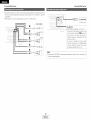
Basic Operation
Basic Operation
STANDARD
DIRECT/STEREO
STANDARD
Turn the SELECT knob, and press the CURSOR
<] or D button to select the optimum mode for
the source.
DIRECT
STEREO
...
ENTER--
_SURROUND
I PARAMETER
(08 -CURSOR
'_ When the "SB CH OUT" parameter is set to "ON".
BACK" at s €sTem setup to "SMALL" or "LARGE'
Disola_
ii,,il,,_ :,
SURROUND PARAMETER
ISet "S
Pro Logic ]]rx Cinema mooe_
i
SELECT
D_o Logic ]Ix Ausic mo(]e
•*The
AVR-786
s eauiDDec
wltn
2-channe
Dla DaOK moaes
excluslve. TOr music
• Select the mode to suit /our taste. <
tnls
mo(]e
t(
acnleve
go()(]
(]Uallt
2-channel
soun(]
wnlie
watcnlng mages n tnls noae tne aua
signals DvDass sucn
slrcults as tne tone circuit ana are transmlttea alreot . resulting
•
gooa
oualll,
sounc
set "S. Back.Co
at tne "SpeaKer
}onfiguratlon
settmg to"lsD
or 2SE
• To Dla n the PL]][x no(]e set "Surround Bacl
a.mo Assign."
• DIRECT mode
use
Dlav n the PL]][x moae
:
HOi::qiiil
x r1
.............. ::_._
-i,,.:>:v
_]
i,i{}r:qE
÷ When the "SB CH OUT" oarameter is set tc "OFF"
S. BACK" at system 3etuD to "NONE'.I
I Press the STANDARDbutton to select the Dolby
Pro Logic gx mode.
• The DolbE Pro Logic ]][ indicator lignTs.
• STEREO mode
÷ The mode svvitcnes as snown
STANDARD button is oresseo
D©LBY PLIIx
DelOW eacr
Pro Logic ]][ Music mo(]e
._=-,r. r
......
_..::
'[...IT G
Pro Logic ]][ Game moae
'h",r',E"
.,r,_ r::,L, _:::_
Dolby Pro Logic mo(]e
t me Tne
Press the SURROUND PARAMETER button, and
press the CURSOR A or 7 button to select the
various parameters.
DTS NEe:6
Play a program source.
-DOLBY
images
Press the DIRECT/STEREO
button on the main unit
or the STEREO button on the remote control unit to
select the STEREO mode.
,:'LIT N
L,gnts
LOGIC _
use tnls moae to aa ust tne tone ana acnleve tne aeslrea sound
wnue watcnlng
Pro Logic ]][ Cinema mode
[ _'iO[::'E:
_[
Press the DIRECT/STEREO
button on the main unit
or the DIRECT button on the remote control unit to
select the DIRECT mode.
F:'i IT L:
_r i,iO[)E
-_[I]PRO
÷ For operating
instructions,
resoecTive
cor¢ 9onents
refer
to
the
rrlanJals
of
tne
D. COMP.
LFE
Tone
Defeat
_L
_-
OFF
OdB
_]
OF
PANORAMA
DIMENSION
CENTER
WIDTH
DefaL
Press the SURROUND PARAMETER button to
select the surround parameter mode.
-DOLBY
PL
x_MODE
4
CINEMA
EQ. ONII_I_I_!_;
D. COMP,
OFF
Tone
I LFE
Defau
I SB CH
Defeat
_
OUT
I_
: OFF
OdB
Yes_
ON
21
I
Set
Disola_
at tne "Power
setting.
Pro Logic ]Ix Game mooe
-i._11.::.:i:i
ENGLISH I
SR CH OUT
"MODE
_
earameters.
q
Yest
ON
÷ See Surroun(]oarameters
_=
t
O_
3
3
i
1 "fora
descratlon
ofthevarious
Basic Operation
Basic Operation
• Surround parameters @
Turn the SELECTknob. and press the CURSOR
<_ or D button
to set the various surround
parameters.
/
•_ \vnen tne surrouna Darameters are set using me DUIIOnS or
me main unit SIOD operating me DUIIOnS after comoletlng
me settings. The settln£ s are aulomaTJcaii, finalized and ine
normal alsDla_ aaDDears after severa seconas
Press the ENTER button to finish the surround
parameter mode.
/
Press the STANDARD button to select the DTS
NEO:6 mode.
÷ The - _oae SWltcnes as sn _wn DelOW eacn lime me
s Dressed
DOLBY PLIIx
1 Play a program
DUIIOn
DTS NEd:6 Mode:
• Cinema:
This mode is eptimum
for playing movies. Decoding is
performed
with emphasis
on separatien
performance
to
achieve the same atmesphere with 2-channel seurces as with
6.1-channel seurces.
This mode is effective
fer playing seurces recorded
in
conventional surreund fermats as well, because the in-phase
component is assigned mainly te the center channel (C) and the
DTS NEO:6
reversed phase compenent
channels).
• Music:
source.
to the surreund
(SL, SR and SB
This mede is suited mainly fer playing music. The front channel
• When
regular
Dressea aria the settlnc_ wl
De COn oletea
• Surround parameters
al pregramsencoaea
The Music mode
oncoaoa
_ Delb Surround
._ recommenaea
fo
o_oroo
muolc
Turn the SELECT knob, and press the CURSOR
<] or D button to select the optimum mode for
the source.
)_
Pro Logic ]Ix and Pro Logic ]I Mode:
The Cinema mede is for use wlIn stereo
ourrouna
Press the SURROUND PARAMETER button to
select the surround parameter mode.
_aKIn J parameter settings, tne display will return t me
cendltlon
several seconas after rne ast r)u[ten was
television
stereo
snows
and
music
and
Press the SURROUND PARAMETER button, and
press the CURSOR A or V button to select the
various parameters.
8ourcoo
The D_ Logic Tleae
ffers the same reDust surround
processing as en£ na Pro Leglc " case the source ;ontent is
neI
of
ODtlmum
Turn the SELECT knob. and press the CURSOR
<3 or D button
to set the various
surround
OUallt
The Game mode is fer playing games. The game mode can or
De used wlm 2-channe audio seurces
Select ene ef me _oaes
Game
• Panorama Control:
Cinema .... Music
Pre Logic
parameters.
or
me surrounc
[re
unit.
malF
[ne setllngs.
This moae extenas me front stere
mage Io ncluae me
surreuna speakers lor ar excmng wraDareuna
effect wire
sloe wa maglng
Select OFF" er "ON"
• Dimension Control:
This central gradually adjusts the soundfield
the front or towards the rear.
÷ When
normal
display
sled
oarameters
oDerallng
The settings
reappears
are sel
me
are automatlca
after
several
Press the ENTER button
parameter
mode.
Jslr g lne DuIIons
buttons
after
on
completing
. -'- allzea
ana me
seconds,
to finish the surround
either rewards
The control can be set in 7 steps from 0 te 6.
• Center Width Control:
This control adjusts the center image so it may be heard enly
from the center speaker; only from the left/right speakers as
a phantom image; or frem all three frent speakers te varying
degrees.
The centre[ can be set in 8 steps from 0 te 7.
• When making parameter settings, the display will return to the
regular condition several seconds after the last butten was
pressed and the setting will be cempleted.
22
L
ENGLISH
J
(FL and FR) signals bypass the decoder and are played directly
so there is no loss of sound quality, and the effect ef the
surround signals output from the center (C) and surround (SL,
SR and SB) channels add a natural sense of expansien to the
sound field.
CENTER IMAGE (0.0 to 1.0: default 0.3):
The center image parameter for adjusting the expansion of the
center channel in the DTS NEd:6 MUSIC mode has been
added.
Basic Operation
Basic Operation
• Surround
INPUT MODE
STANDARD
SURROUND PARAMETER
CINEMA EQ, (Cinema Equalizer):
The Cinema EQ function gently decreases the level of the
extreme
high frequencies,
compensating
for overly-bright
sounding motion picture soundtracks. Select this function if the
sound from the front speakers is too bright.
This function only works in the Dolby Pro Logic ]][x, Dolby
Digital, DTS Surround and DTS NEO:6 modes. (The same
contents are set for all operating modes.)
-SURROUND
PARAMETER
--CURSOR
ENTERFUNCTION
SELECT
D.COMR (Dynamic Range Compression):
Motion picture soundtracks have tremendous dynamic range
(the contrast between very soft and very loud sounds). For
listening late at night, or whenever the maximum sound level is
lower than usual, the Dynamic Range ComFession
allows you
to hear all of the sounds in the soundtrack (but with reduced
dynamic range). (This only works when playing program
sources recorded in Dolby Digital or DTS). Select one of the
four parameters ("OFF",
"LOW",
"MID"
(middle) or "HI"
(high)). Set to OFF for normal listening.
--SURROUND
ON SCREEN>
BACK
INPUT MODE-
r
elect an input source set to digital (COAXIAL/
OPTICAL) (_
page 39).
Press
the SURROUND
PARAMETER
The surround
earameter menu
s displayed button.
Example: DVD
FUNCT
-Dolby
O
M8
ON
BVH/VUP
C NEMA
3, CAMP.
FE
Tone
Dig
EQ,
3efeat
_a
EX-
ON t
OFF
Remote
contrc
SB
unit
CF
)efcult
)UT
!
Press the STANDARD
STANDARD
(Dolby/DTS
button
to select
Surround) mode.
ES
DSCRT6
>C NEMA EQ,
LFE
Tone
Defeat
-
ON
_
0dB
r@J_l : OFF
O
Yes4
|
Press to
the"AUTO"
INPUT MODE
button to set the input
mode
or "DTS".
-DTS
oj
0dB
MTRX
[
_
"
unit
SB CP
Defau
)UT
t
ES DSCRT
Yes4
' Press the SURROUND PARAMETER button,
press the CURSOR
various parameters.
the
A or _7 button
to select
1
LFE (Low Frequency Effect):
This sets the level of the LFE (Low Frequency Effect) sounds
included in the source when playing program sources recorded
in Delby Digital or DTS.
If the sound produced from the subwoofer sounds distorted
due to the LFE signals when playing Dolby Digital or DTS
sources when the peak limiter is turned off with the subwoofer
peak limit level setting (system setup menu), adjust the level as
and
the
Turn the SELECT knob. and press the CURSOR
<_ or > button to adjust the parameter
settings.
÷ Wher uerforming this oaeration from tne main units 9anel.
_ress the SURROUNDMODE button men _L n the SELECT
<nod ano select Dolb J Pro Logic Ix or DTS NEO:6
) Press the ENTERbutton to finish the surround
Play a program
symbol.
• The Dolby Digita
source
nalcator
with
the
gnts
wnen playing Dolby Dig ta
sources
_=_
or
olayingDTS sources
parameter mode.
PZ_
-:'oC--
Lights
ugnls
oressea
maKIDg oarameter
seYYings, tne CHSDIa_ .
reYurn YO me
senclltlen
_everal
seoencis
after me
_st DuEon
was
and Yne se_Ilng v_
De com_
le_ec
÷ Operate the SURROUNDBACK DuEor
IO svvltcn Surround Back CH QN/OFF.
• The SURROUND EACK indicator
Igms wnen tne SURROUNDBACK
÷ When DTS encoded movie software
is played, it is
recommended that the LFE LEVEL be set to 0 dB for
correct DTS playback.
÷ When DTS encoded music software
is played, it is
recommended that the LFE LEVEL be set to -10 dB for
correct DTS playback,
This enables the tone control. This can be set individually
the separate surround modes other than DIRECT mode.
• When
regul;
-'o
_ --
necessary.
Program source and adjustment range:
1. DolbyDigital:
-10dBto0dB
2. DTS Surround: -10 dB to 0 dB
TONE:
BB DIGITAL
• The DTS nalcalorgins wnen
DuEon
parameters _3_
STATUS
SU_._,uND----:'_"-:0._-ugnts
S or
23
I
ENGLISH I
for
Basic Operation
Basic Operation
SB CH OUT (Surround Back):
(1) Multi-channel
• OFF:
seurce
Playback is cenducted
speaker.
• NON MTRX:
without
using
the
surreund
back
• Dialog normalization
The input signal can be checked by pressing the remote contrel
unit's ON SCREEN button.
The dialog nermalizatk_n functien is activated automatically when
playing Dolby Digital program sources.
Dialog nermalizatk)n is a basic function ef Dolby Digital which
automatically normalizes the dialog level (standard level) of the
signals which are recorded at different
levels for different
program seurces, such as DVD, DTV and ether future formats
that will use Dolby Digital.
These centents can be verified with the STATUS or ON SCREEN
buttens.
SIGNAL:
Displays the type of signal (DTS, DOLBY DIGITAL, PCM, etc.).
fs:
The same signals as those of tile surreund
eutput from the surround back channels.
• MTRX ON:
The surreund back channel is reproduced
processing.
• ES MTRX:
channels
are
Displays the input signal's sampling frequency.
FORMAT:
using digital matrix
When playing DTS signals, the surround back signals undergo
digital matrix processing fer playback.
• ES DSCRT:
When a signal identifying the seurce as a discrete 6.1-channel
seurce is included in the DTS signals, the surreund back
signals included in the seurce are played.
• PL]][x Cinema:
Processing is perfermed with the Cinema mode of the PL]][x
decoder and the surround back channel is reproduced.
• PL][x Music:
Processing is performed with the Music mode of the PL]][x
deceder and the surround back channel is reproduced.
(2) 2ch source
• OFF:
Playback
speaker.
•ON:
• Checking the input signal
Displays the input signal's number of channels.
"Number of front channels/Number ef surreund channeld
on/off".
"SURROUND"
is displayed
recorded in Delby Surround.
without
using
the
surreund
Playback is conducted using the surround back speaker.
÷ This operation can be perfermed directly by pressing
SURROUNDBACK button.
back
2-channel
signal
OF:F::!!!;E!:I
seurces
The
OFFSET:
Displays the dialeg nermalizatien
offset value.
Displays the special identificatien signal recorded in the input
signal.
"MATRIX" is displayed when matrix processing is conducted
en the surreund back channel, "DISCRETE" is displayed when
discrete precessing is conducted.
Net displayed if an identification signal has not been recorded.
screen information
is displayed
in the fellowing
erder when the ON SCREEN button is pressed repeatedly:
OSD-1
Input signal
OSD-2
Input/output
OSD-3
Aute surround mode
OSD-4-10
Tuner preset stations
the
Mode:Dolby
number
currently
FLAG:
• In addition,
is cenducted
fer
Display
LFE
Digital
Mode:DTS
EX
SIGNAL:DOLBY
DIGITAL
fs
:48kHz
FORMAT:3/3/,
1
OFFSET:-4dB
FLAG
:MATRIX
ES
DSCRT6.
1
SIGNAL:DTS
fs
:48kHz
FORMAT:3X3/,1
FLAG
:DISCRETE
NOTE:
• OSD-3:
This is displayed when the auto surround mode is set to
"ON" and the input mode is set to "Auto".
It is net displayed when the input mede is set to "Analog"
or "EXT. IN".
24
I
ENGLISH I
indicates
the
•..... ::I-:::IB]
nermalization
level
when
the
playing program is normalized te the standard level.
Basic Operation
Basic Operation
STANDARDFUNCTION
INPUT MODE
FUNCTIONPress
A button.
; Switchthe
i0 CURSOR
the Audio Delay
adJUStmen i
Screen
ENTER-CURSOR
÷ With a movie source, _or example, adjust so that
movement of the actors' lips is synchronized
with
sound.
STANDARD/NIGHT
the
the
INPUTMODE-
When listening at night or at lower volumes,
improves listenabiiity.
the night mode
Press and hold the NIGHT button for several seconds
to enter
the night
mode.
• Canceling night mode:
Press and hold the NIGHT button again.
• The night mode only works when playing program
recorded in Delby Digital or DTS.
sources
• When watching a DVD or other video source, the picture on the
meniter may seem delayed with respect to the sound, in this
case, adjust the audio delay te delay the sound and synchronize
it with the picture.
• The audio delay setting is stored separately for each input
source.
• This adjustment can be performed with the system setup
(_,._Ppago 42) or from tho romoto control unit, as doscribod
below.
Select the input source.
Example: DVD
_UNOr 0_,
ovo/VOF
0
Main
,%
qemote comroJ unn
Jnlt
Press
the"AUTO".
INPUT MODE button to set the input
mode to
Select DoIbytDTS Surround.
STAN_Aa_
Mai
_rAN_A_D
unit
'£emote
25
I
ENGLISH I
comrol
unn
• The audio delay setting does not apply when playing in the EXT.
IN mode or in the analog input direct or stereo mode.
Basic Operation
Basic Operation
This unit is equipped with a high performance DSP (Digital Signal Precessor) wMch uses digital signal processing to synthetically
recreate the sound field. One of 7 preset surround modes can be selected according to the program seurce and the parameters can
be adjusted according to the conditions in the listening room te achieve a more realistic, powerful sound.
1
The front left channel signals are output to the surround and surreund back left channels, the front right
channel signals are output te the surround and surround back right channels, and the in-phase component
of the left and right channels is output te the center channel. Use this mode to enjoy stereo sound.
2
Select this when watching
3
Use this mode to achieve the feeling ef a live concert in an arena with reflected
directions.
4
This mode creates the sound field of a live house with a low ceiling and hard walls. This mode gives jazz
a very vivid realism.
5
Use this te enjoy video game sources.
monaural mevies for a greater sense of expansion.
sounds coming frem all
Select this to emphasize the sense ef expansion for music sources recorded in stere<>. Signals consisting
of the component difference of the input signals (the component that provides the sense ef expansien)
srocessed for delay are output from the surround channel.
Select this mode to enjey a virtual sound field, produced from the front 2-channel speakers er headphones.
÷ Depending on the program source being played, the effect may net be very noticeable.
In this case, try other surround medes, without worrying about their names, to create a sound field suited to your tastes.
NOTE:When playing sources recerded in menaural, the sound will be one-sided if signals are only input to ene channel (left er right),
so input signals to both channels. If you have a source component with only one audio output (monophonic camcorder, etc.)
obtain a "Y" adapter cable to split the meno output to two outputs, and connect to the L and R inputs.
• Personal memory plus
This set is equipped with a personal memorize function that automatically memorizes the surround modes and input modes selected
fer the different seurces. When the input source is switched, the modes set fer that source last time it was used are automatically
recalled.
÷ The surround parameters,
each surround mode.
tene control settings and playback level balance fer the different
output channels are memorized
26
L
ENGLISH
J
fer
Basic Operation
Basic Operation
SURROUNDMODE TONECONTROL
'_ Wnen tureen
--DIRECT
SURROUNDMODE
E
SURROUND
_ STEREO
_ DC_B_PROLOGIC]Ix_
MONa MOVIE_ 5CH/TCHSTEREO_ DTSNEO:6
ROCKARENA_ JAZZCLUB_ VIDEOGAME-
--SURROUND
PARAMETER
--CURSOR
ENTER
CH SELECT/
--
71RTUAL
SURROUND
_ MATRIX
'_ To select the surrcuna rnooe Nnlle aajustlng tne surrouno
Darameters
tone defeat
or [one control.
Dress the
SURROUNDMODE button, tnen )Derate Tne selectol
"-_i.5.._-"
PARAMETER
SELECT
TONE DEFEAT
2
Press the SURROUND PARAMETER button, and
press the CURSOR A or V button to select the
various parameters.
• To operate the surround mode and the surround
parameters from the remote control unit
counierclocK_/ise
ress
button
and hold in the SURROUND PARAMETER
to select the parameter
you want to set.
÷ The parameters
surroura
moues
ano oarameters
Press the
parameter
Select the surround mode for the input channel.
s _AN+}A_O
SlM_IlON
CURSOR<1 or
settings.
D button
to adjust
wnlcn
are
can De set olffer
_
for the differem
(Refer to "Surrouncl r'ncues
alsDlaved.
cage 56)
the
Display
the parameter
turn the SELECT knob
you want
to set it.
to adjust,
then
Press the ENTERbutton to finish the surround
parameter mode.
Remote control unn
• When
÷ The surrcuna moae SWIICnes
" IRe TallOWing oraer eacr
Time The DSP SIMULATION DuEon S E essea
MONa MOVIE_
ROCKARENA
MATRIX_- VIDEOGAME--
• When making 3arameter settings, tne (]lsDla_ wi return to tne
regul;
senclltlen
_everal
seoenas
after IRe _SI DuEen
was
oressea
ann
tne
setting
\_
De cenll
letec
Press the SURROUND PARAMETER button to
the surround
narameter
cencHtler
oressecl
aRc
parameter
IRe
setting
"
Tone
SB
Defeat
CH
OUT
_ef au i t
setting
IS
tne
_econcis
w
• Surround parameters
De carl
OISDla_
aTte
tne
w_
las_
return
DUIton
to
tne
was
z)letecI
_4_
parameters from the main unit's panel
mode.
ROOM SIZE:
This sets the s_ze ef the sound TleIo
There are five
ARENA_
I0
_]
]
4
Turn the SELECT knob to select the surround
1
If
mode.
]
:
Oh
e s_
OFF
÷ The surrouna Darameter
SWltDnes
in tne _OllOwIng oraer
eacn time me SURROUNDPARAMETERDuEon S Dressed for
the different surround modes.
sma
neo.s
meulum-sma
qlea
EFFECT LEVEL:
•_ v_/nen iurneo
This sets tne strengtn _f the surround
The evel :ar beset - 15 steps frorT
DIOCKWlSe:
- DIRECT_ STERE_-* DOLBYPROLOGICIx
MONOMOVIE_ 5CH/7CHSTEREO_ DTSNEO:6÷
--
seeings:
mealum-large/
ann
urge
sma
recreates a small seuna field
_r _e _ arge seuna tlela
mealum
-ROCK
ROOM S
I ZE
EFFECT
settln
severa
JAZZCLUB--
• Operating the surround mode and the surround
enter
maklnc
regular
ROCKARENA_ JAZZSLUR_ VIDEOGAME
• the
MATRIX
seems
olsterteo
DELAY TIME:
The aela_ time can De set Ivltnm tne range of 0 te 110 ms onw
the
VIRTUALSURROUND_
sauna
matrix
moae
TONE CONTROL:
This can be set individually
DIRECT.
27
I
ENGLISH I
effecl
to 15 Lower tne eve
fer each surround
mede except
Basic Operation
Basic Operation
• Adjusting the sound quality (tone)
The tone control function
r Press
vvili not work in the DIRECT mode.
the TONE CONTROL button.
•_ The Tone s Jttcr es as follows
DUtTQF
eacr ttme me TONE CONTROL
You can adjust the channel level either according to the playback
sources or to suit your taste, as described below.
Press the CH SELECT button to select
speaker whose level you want to adjust.
•_ Tl'e cnannel swltc qes as snown Below eacn time tne
the
DUIIOn
s oressea
_ D[essec
BASS_TREBLE
Turn
thetreble.
SELECTknob to adjust the level of the
bass or
÷ To inc aase me Dass or Treble:
Turn me control ClOCKWISe. (The Bass 3r treble sou-a can Be
ncreasea uD to +12 dB in steBs 3f 2 dB3
÷ To decree se IRe Bass or ireBle:
Tur'- IRe conII ol counterclockwise
Tile bass C treDle sauna
san De aecreasea down to -12 dB in steBs of 2 dB.l
•
Tone
defeat
mode
f vo_ ao not want me [)ass aria treble to _)e aa ustea, turn on tne
tone
..........defeat mode
Press
the
TONE DEFEATbutton.
•_ When the sJrouna DBCKsBeaKer sett ng IS set to "lsD" for
SBeaker Configuration". this is set to 'SB
"_ "SB' aBBears onw wnen me "Power AmB Assign." setting
s me surrouna DaCKmoae
Press the CURSOR < or D button to adjust the
level of the selected speakel:
÷ The aefault setting of the cnannel lever s 0 dB.
÷ The level of the selectea s[_eaKer can Be aa ustea wlmlr
me
range of +12 to -12 dB BV Dressing me CURSORButtons
"_ The SW channel level can be turned otf bY decreasln g it one
step from -12 dB.
OFF ee -12 dB ee +12 dB
'_ The signals do not pass through the bass and treble
adjustment circuits, thus resulting in higher quality sound.
28
L
ENGLISH
J
Basic Operation
Basic Operation
FUNCTION
BAND
PRESET
TUN,NG
TUNER
_PRESET
MODE_
[ Auto tuninq
1
]
Set the input
source
to "TUNER".
FUNCf ok
TUNE_
_'=__SHIFT
MEMORY_
_BAND
(Main unit
0N/STANDBY SHIFT
ONSCBEEN
TUNING
::{emotecontrol unib
Watching the displa); press the BAND button to
select the desired band (AM or FM).
0
• DEFAULT SETTINGS
Press the MODE button to set the auto tuning
mode.
• This unit is equipped with a function for automatically searching
for FM breadcast stations and storing them in the preset
memory.
• The "Auto tuner
"System
setup"
preset"
(_
operation
can also be performed
at
page 41).
MODE
,
switch on the main unit.;
,,The unit automatically
Stations.
÷When
begins
searching
for FM broadcast
D1 ~ D8
90.1 MHz
E1 ~ E8
90 1MHz
F1 ~ F8
90.1MHz
G1 ~ G8
90.1MHz
in order
Manua
Press the TUNING (+) or (-) button.
÷ Ant )ma]:lC searching
the first FM broadcast station is found, that station is
stored in £he preset memory at channel A1
Subsequent
stations are automatical!y stored
_
[uRea
Deg ns. men stoos wRen I STaTler]
IF
at
preset
channels A1 to AS, B1 tO B8, C1 to C8, D1 tO D8, E1
to E8, F1 to F8 and G1 to G8 fol a maximum of 56 stations.
÷ Channel A1 is tuned in aft:el the auto preset memory
• When In me auto tunmg moae n me FM r)anc the "STEREO"
nalca_or iig IS en me alSDIa wRen a szereo r_reaacas_ s tunea
At _Den freauen@e. < rne nelse
s mu_ea
aria me TUNED"
and "STEREO" indicaters turn off.
operation is complete &
• If an FM station cannot be preset automatically due to peer
reception, use the "Manual tuning" operatien to tune in the
station, then preset it using the manual "Preset memery"
operation.
• To interrupt this function, press the 0N/STANDBY switch.
29
I
Er,IGLISH
I
Basic Operation
Basic Operation
The :)reset tDroaacast
r
et the input source to "TUNER".
Watching
the display,
select the desired
band press
(AM the
or BAND
FM). button to
Press the MODE button to set the manual tuning
mode.
Use the "Auto
tuning"
or "Manual
tuning"
operation
to tune in the station to be preset in
the memor):
Press the MEMORY button.
and select the desired
memol 3"block (A to G).
÷ Check tna_ me o_splav's "AUTO"
carl
De
cnecKea on tne on-screen
Press the ON SCREENbutton repeatedly until the
"Tuner Preset Stations" screen appears on the OSD.
A1
A2
Press the SHIFT button
stations
CUsDlav.
indicator turns off
Tuner
FM
FM
3resef
87.
50MHz
89.][_Hz
A3
A4
A5
A6
A7
FM 98.10MHz
FM107
90MHz
FM 90.10MHz
FM 90.10MHz
FM 90.10MHz
A8
FM
Star
ons
90.10MHz
•
Press the TUNING (+) or (-) button to tune in
the desired station.
÷ The freouency
elcl
cnanges
comlnuous.
Hnen tne DUt_on Is
"
• When the manual tunmg _]ooe sset FMstereoDroaocastsare
receweo - monaura anotne
STEREO nolcatorturnsofl
Press the PRESET(+) or (-) button to select the
desired preset channel (1 to 8).
Press the MEMORYbutton again.
• Store the statior
• To [:_eset
n Iota
channels
omer
cnannels
• 56 Droadcasl
r( 8
q each
q the areset memory!.
repeat
stations
sIeDs
_( zl
carl
)e oreset
• [)lOCKS A to e
30
I
ENGLISH I
8 statK)ns
q
I
Watching the display, press the SHIFTbutton to
select the preset memo_" block.
2
Watching the displa); press the PRESET • (+) or
• (-) button to select the desired preset channel.
Advanced
Advanced
Operation
Operation
OFF-
1. CD player (CD), CD recorder and MD recorder (CDR]MD)
system buttons
--ON/SOURCE
3. Tuner system buttons
I
NUMBER-
-_® C ®!
MODE1-
--MODE2
4w_l, I_1_
•
I_
: Manua, searcr
StoD
Pla'_
14141,_
II
: Auto searcn _cuel
: Pause
DISC SKIP +
forward and reverse
Switch d Bcs tfor CD cnangers on,w
2. Tape deck (TAPE) system buttons
SHIFT
: Switch ereseT cnannel rat ge
CHANNEL +, - : Preset channel UP aown
TUNING +,: Freauencv uoldown
RAND
Sv tcn between tne AM and FM bands
MODE
:Switcn Deiweer amo ana mono
MEMORY
: Preset memor,_
r Set the MODE 1 switch to "AUDIO".
AUB 0
*TUNER
-VDEQ
OOSITIeR
Set the MODE 2 switch to the position for the
component to be operated (CD. CDR/MD or
TAPE ).
_1_1
•
CDR/MD_
CD_
_TAPE
_ZONE2
I_
_11
_ZD
DVD IVOP_
_ _lDBS
VCfl
A/B
CABLE
: Rewma
Fast-forwara
Sl )D
Forwara
Reverse
DlaV
DiaV
: SwitcF between
decks A and B
,.i=.
Operate
÷
For deta
the audio component.
s. refer to the comDonent's
÷ While tn,s remote
-_-area controllea
s)rne
"emoTe
comoonenT
)peratlng
instrucl
)ns.
comrol
,s 3omoatiDle
w,m a w,ae range of
comDonents.
I ma', De IRe case _nat
moaels
cannot
De c 3eratea
wltn
IRiS
control.
31
I
ENGLISH I
can De oDeratea
wner
the
switch
s at
AUDIO"
Advanced
Operation
Advanced
Operation
1. Digital video disc player (DVD) system buttons
*DENON
gnu >tner
setting
tne areset
• This emete contr
omer
makes
}f cen-oonents
nlenlop.
unit can De useD t
manufacturers
A/itnout
using
_,an De }oerateq
berate
me
registering
me manufacturer
of the comoonem
3t ot oreset
cedes
_
End of this manua
• Operation
s not L_OSSlbie for some
comoenems
learning
runoiioR
D
• The slcj qals tor me oressed buttons are ematteu wnlle
setting
the E"ese; nemor
avelq accldema
_oeratlon covel me
emote
of
oreset
D
as ShOWn in tne
centre
]nits
transmitting
wmoew
wnlle
• Depending on me mode anq vear of manufacture
cannel
De
istea
nlooels,
setting
C
me
Remor
In the
• Some
sea
for
some
St OT preset
manufacturers
use
Roaels
eveR
_ tnev
mrs tunotlon
are
of
makes
codes
more
than
one
type
of remote
9@
contre[
Set the MODE 1 switch to "AUDIO" or "VIDEO".
• The oreset memer, car De set Tor one cemponent enly among
me fellewing
]DR/MD
DVDVDP and DB,C/CABLE
AUO O
.....
ceDe Refer to the ncluaea ist OToreset ceDes tc cnange me
number and venr 7 correct ooeratlon
o _C
5
,VDEO
÷ Set to me AUDIO s de for the CD Taoe DeCK or CDR ME
9osmon. and to the VIDEO side for the DVD'VDP
DBBiCABLE. VCR }r TV sosmor
_et the
MODE 2
switch
to the component
The {)reset codes
•
to be
registered.
CDB/MD_
CO_
DVD/VOP_
Press
the
same time.
VCH
are as follow, <
factor, and after esettlnc
• T\ VCR .........................................
• CE TAPE .......................................
• CDR MD ........................................
• DVD /DP .......................................
• DBSCABLE ...................................
JDen
snlDmenr
_......
me
HITACH
DENON
DENON ]DR
DENON DVD)
ABC CABLE
_TAPE
_ZONE2
_TV
DBS
CABLE
DENON
ON/SOURCE
OFF
ON/SOURCE
and OFFbutton at the
• The indicator starts flashin j.
I_
_1_1, I_1_
•
=VDEO
4
_1=
Referring
to the included
list of preset codes.
press the NUMBER buttons to input the preset
code (a 3-digit number)
for the manufacturer
of
the component
whose signals you want to store
in the memor?:
To store the codes of another
memory, repeat steps 1 to 4.
_1_
I_
•_ Set to the AUDI D s de for the E D. TaBe deck ar CDR MD
oosmon
and ro me VIDEO stae for the DVD/VDR
DBS/CABLE VCR or TV oosmon.
9
Set the MODE 2 switch
want to operate.
component in the
CDR/MD
to the
component
you
I_t_1, _
II
0 ~ 9,+10
DISC SKIP +
DISPLAY
MENU
RETURN
TAPE
CD_ q..F_zoN[2
A
OVDIVDP_
Operate
_[V
VCRJ_BS/a_
the component.
÷ Fc Details. refer Tome component s operating nstructlons
"_ Some models cannot De ooeratea wlin Dis remote centre
unit,
32
I
ENGLISH I
: Power on stanaDv
: DENON DVE uovver c_"
: Manual searcn forwarD anD reverse
:
Stoo
: Pla_
:
:
:
:
:
:
:
Auto search tto beginning of tracK
Pause
NumDel
Disc skio for DVD changer onlw
Switcf atsula_
Menu
Return
SETUP
V, _1, I_
: Setuo
: Curs3ruB.
ENTER
: Enter setting
• Some manufacturers
Down
use different
eftana
ngm
names for the DVD remote
centre outtons sc also reTer te me
contrel Ter mat con oenem
nstruc'qens
_ remote
Advanced
2. Video
Operation
Advanced
disc player (VDP) system buttons
3. Video deck (VCR) system buttons
4, Digital broadcast satellite (DBS) tuner and
cable (CABLE) system buttons
O
¢89_
¢¢9
CN_
-
-
0
8
Z¢9_
D
0
_ENON
ON/SOURCE
4_1, I_1_
• Power op_standb
Manua search (forward ana reversel
ON/SOURCE
41_1, _
•
Stop
•
Plav
I_
Auto searc q _cuel
Pause
Number
0
O
DENON
DENON
I_
141h4,_
II
0 ~ 9, +lg
-
II
Channel e, -
.coo:
Power on/star ]b_
: Manual search (forwara ana reverse
StOD
: Pla'.
Pause
: Channel L w sown
ON/SOURCE
MENU
RETURN
Power on/_tanaDv
: Menu
£eturr
A, T, _1, I_
ENTER
: Cursor up. down. left ana ngm
: Entel
CHANNEL +, - : Channel uD/aown
0 ~ 9, +10
: Num_el
DISPLAY
: Switcf alSDlav
VOL e, -
33
L
ENGLISH
]
: VOlUme -,L/aown
Operation
Advanced
Operation
Advanced
5. Monitor TV [TV) system buttons
-MAIN ON
ZONE2 OFF-
I0
o
c::s_c::2_
i'G @ ®i
-,:C@ _i
NUMBER-
r _
MODE1-
_'_
_r
-MODE2
3_3'
"Punch Througn is a function allowing yo[ t operate me PLAY
STOP MANUAL SEARCH ana AUTO SEARCH burdens on }E TAPE
CDF ME
DVD/VDP
VCF conoonen_s
,vnen
- me
DBS'CABLE or TV moae
Set the
Bv defaull
MODE 1 switch
nommg s se_.
to "VIDEO",
AUB O
_
_:
_
_:
'
,VDE0
DENON
ON/SOURCE
MENU
RETURN
: Powe' on/stanaDy
Menu
Return
A, T, _1, I_
ENTER
CHANNEL +,0 ~ 9, +10
DISPLAY
: Cursor uo acwn.
: Enter
Channel J_iaown
: Number
Switch d sma.
TV/VCR
VOL +, -
• c,., }E
oDeratea
the
MODE2
switch
registered (DBS/CABLE
to the
component
or TV).
cD__.,r[Ap_
_z0_
C2ND
left and nghl
DVD/VBP_
VCR_
_
_TV
_)BS/CAE¢£
Press
the time.
ZONE2OFFand MAIN ON buttons at
the same
• The inaica_or starts flashing
}DR
AD ana TAPE con-sonen_s me _)uttons can De
me same wa as for DENON aualo corrsonems
OOSl[IOn
to be
_J3R/M0
: Switch uewvee- Tv' and video maveJ
vomme up/down
;_ page 3'
• A T\ can De oDeratea wnen me switch
TV
t Set
s at the DVD/VDP VCR
CD
1
TAPE
'
CDR/MD
'
3
DVDiVDP
'
4
VCR
'
5
No setting
'
0
34
I
ENGLISH I
2
Operation
Advanced
Operation
Advanced
• ZONE2 speaker out and pre-out carl be used when "ZONE2"
is selected at "Power Amp Assign."
in the "System
Setup"
Operation
menu.
in this case, surround back speaker out cannot be used for MAiN ZONE.
• When a sold separately room-to-room remote control unit (DENON RC-616, 617 or 618) is wired and connected between the MAiN
ZONE and ZONE2, the remote-controllable
devices in the MAIN ZONE can be controlled from ZONE2 using the remote control unit.
• For the AUDIO outputs, use high quality pin-plug cables and wire in such a way that there is no humming or noise.
• For instructions on installation and operation of separately sold devices, refer to the devices' operating instructions.
• When the main unit is set to the recording output mode, ZONE2 remote control button cannot be operated.
• When using the SURR.BACK/ZONE2
amplifier as the ZONE2
• The SPEAKER OUT and PRE OUT terminals can be used simultaneously in ZONE2.
• To use the ZONE2, turn on the ZONE2 button.
• The output of the ZONE2 SPEAKER OUT terminals can be adjusted with the remote control unit's ZONE2VOLUME button.
[System configuration and connections example]
Using this unit's internal amplifier as the ZONE2.
MAIN ZONE 5.1-channel systems
Monitor
FL
53
DVD player
ZONE2
FR
This unit
.....
Input
ZONE2 SPEAKER OUT
RC-616
::
::
PROGRAMMABLE
REMOTE CONTROL UNIT
SYSTEM REMOTE
CONTROL UNIT RC-978
............
: ROOM-TO-ROOM REMOTE CONTROL SYSTEM
(separately sold) control line
. SPEAKER cable
•_ Refer to "Connectk>ns"
35
I
ENGLISH I
(_
page 16).
Advanced
Advanced Operation
Operation
ZONE2 OFF-
ZONE2 ON
FUNCTION ZONE2/RECSELECT
"When the the
ZONE2
set to
TUNER,
preset SOURCE
Channel function
Can be is
Selected
using the
CHANNEL butt0n on the remote
FUNCTION÷ This is only possible when the main unit in the ZONE2 mode
(_
page 4%
MODE1ZONE2
1
ZONE2/REC SELECTbutton to display
the ' ZONE2 SOURCE on the display.
E
Set the MODE1 switch to the "AUDIO".
i
AU
D
0
•_ Tile dlscJav SWlTcnes as fOllOWS eacn Time me CUTIOn IS
cressed.
ZONE2 _
,VDEO
REC
Set the MODE 2 switch to the "ZONE2".
CDR/mDq
rTAPF
00_
_ZONE2
Turn the
you
want
FUNCTION
knob to select the source
to output
appears
on the display.
DVD/VDP_
Start
playing
the source
"escectlve
÷ To cance
Press
nsTructlons.
"efer to me
man[dis
ZONE2 button.
"SOURCE"
ZONE2
:_O'- --
the
ZONE2 ON button.
of rne
comdonents.
Turn the FUNCTION knob and select
the
_ _TI
_BS/CABLE
to be output.
Press
÷ For ocerat#lg
VeR
ugnts
"_ To cancel the ZONE2 mode:
Press the ZONE2OFF butt )n.
Press the
FUNCTIONbutton.
•_ The ZONE2 source swltcnes
• The sig lals OT The source selected in tne ZONE2 -f_oae are also
output from the VCR and CDF/TAPE recording utcut terminals
• Digital signals are ne_ utcut te the ZONE2 out_)ut terminals
direct .
The output level of the ZONE2 SPEAKER OUT
terminals
can be controlled
pressing the
VOLUME button on the remote control unit.
•_ Defaul_ semng (ZONE2 VOLUME
---dB
MINIMUM
LEVEL1:
36
I
ENGLISH I
Advanced
Operation
Advanced
FUNCTION ZONE2/RECSELECT
Operation
If the indication on the display is not normal or if the operation of
the unit is not correct, then the microprocessor should be reset
by the following procedure.
Switch
off
th e
unit
using
the
main
unit!s
POWER Switch.
POWER
Keep both
SPEAKER
and turn on the unit
SPEAKER
Chec k that the
second
inter_als
• Tile microprocessor
Press the ZONE2/REC SELECT button to display
the "RECOUT
SOURCE" on the display.
disola_
swltcnes
as follows
each
time
me
Dultor
s
0ressea.
ZONE2
REC
• This unit is equipped with a last function memory which stores
the input and output
setting
conditions
as they were
immediately before the power is switched off.
This function eliminates the need to perform complicated
resettings when the power is switched on.
• The unit is also equipped with a back-up memory. This function
provides approximately one week of memory storage when the
main unit's POWER switch is off and the power supply cord
disconnected.
Turn the FUNCTION knob to select the source
you want to output appears on the display.
Set the recording
mode.
'_ Y-OI operating
9sTrucTIQnS
refer
to the
cor'nDoneni
on wnlcn yOU ',A/anT TO recora
÷ To cance
turn
the FUNCTION
s depressed
main unit,s
POWER Switck
a_
'_ The
A and B button
by pressing
the
knob and select
manual
o _ me
"SOURCE".
• Recording sources other than digital inputs selected in the REC
OUT mode are also output to the ZONE2 audio output
terminals.
• Digital signals are net output to the REC SOURCE or audio
output terminals.
• The DIGITAL IN's signal selected with the FUNCTION knob is
output to the DIGITAL OUT (OPTICAL) terminal.
37
I
ENGLISH I
entire
display
is flashing
and release
the buttons.
at
!:
will be initialized:
• if step 3 does not work, start over from step 1.
• If the microprocessor has been reset, all the button settings are
reset to the default values (the values set upon shipment
the factory).
from
Advanced
Advanced
Setup - Part 1
Setup - Part 1
Tile AVR-786 is equipped with an intuitive and easy-to-understand
equipped with an alphanumeric front panel display that can also be
settings. We recommend that you use the on-screen display when yeu
Some representative frent display and on-screen display examples are
Use System Setup to custemize a variety of settings to suit your listening environment.
For the centents of a system menu and the initial setting ef this unit (/::_= page 48, 49).
on-screen display, and is
used te check and adjust
make system adjustments.
shown belew.
[ On-screen
You can change the settings using the buttons on the remote centrel unit.
i,_,ll
[ Front display ]
_System
MODE 1-i1!
I
Setup
Exit
-ENTER
[ On-screen display ]
SETUP--
System
-CURSOR
Setup
], Auto
Setup
2. Speaker
Setup
>3. Input
Setup
4, Advanced
Playback
5.
Option
........
i_ 1
....
':::=i
............................
_:::-_
[To select a menu,
^^_
J
theCUR_u_
_
or
V
! Setthe MODE 1 s_Jtch to "AUDIO".
Dutton._
Press the SETUP button
to display
the "System
Setup"
menu.
Press the CURSOR
A or V button
the menu.
then
press
the
[
:] ]
!i::{ii! I::
_
I::
I
t
'l
4, Advanced
5. Option
Playback
Setup
Exit
k,o.
[
:h [) i :iiiii L::_ii_
]
--
_
.....
,._
..
setup
I
>'.(D×'
_'t,_'JoLe_sJ
i,gn.)F
4: IFunnPU_iFun_ti_°ne
title _
i::_]
6. AuEdoe°TLnePU
Level
t pMe°dee t
i
to enter
To change a setting, first select it
pressing
the CURSOR & or V
button,
and
then
change
the
setting pressing the CURSOR < or
[> button.
Press the ENTER button
the new settings.
Setup
Speaker
| ILvA_fTI
i-l[;]il!l
Exit
Pressselected
the ENTER
the
menu. button
Setup
Setup
3. Input Setup
Input
>1. Digital
In Assign.
2. Ext
In
SW Level
Input
Function
Level
Function
Rename
5: Video
Input
Mode
Auto
Tuner
Preset
ENTER button.
to confirm
Press the SETUP button to return
to the "System
Setup" menu and
to return
_::_ _i:
1. Auto
_>2.
L
Setup
Exit
System
press
.
[ Display ]
again
i1.! I
P
Input
Setup
4. Advanced
Playback
5. Option
Setup
Sub-menu title
4
i-I[;]
_uto
i-I[;]
to select
display ]
to the main
screen.
>COAX IAL1
COAX IAL2
OPTICAL1
OPTICAL2:
13-l.
: _)
: AUX
: DVD
TV
Digital
In
Defaultl[
Press
<1
................
k_.
_mhmJm.._mm_.,.J._m_u
Power
Amp Assign
S, Back
[ ,ne
...........
[
CURSOR
:]U:::i
u "i;c_:iii;
e "i:: _iii: "i:_IIp•-A::
[
1, Auto
Setup
2. Speaker
Setup
3, Input
Setup
4. Advanced
Playback
5, Option
Setup
ISystem
Setup
>Exit
the
button to execute,
Assign•
I
:1:E:xit:
38
I
ENGLISH I
Current setting
n.
Advanced
Setup - Part 1
Advanced
This setting assigns the digital input terminals
the different input sources.
4
11
the
CURSOR A or _7
Setup"
at the "System
Press
"Input
then
press
• The
InDUt
of the AVR-786 for
button
to select
Setup"
menu.
the ENTER button.
SetL a" screen
ac Dears
• The OPTICAL 2 terminal en the AVR-786's rear panel is
equipped with an optical digital output terminal for recording
alglta signals on a CD recorder, MD recorder or other algltal
1. Auto
Setup
2. Speaker
Setup
3. Input
Setup
4. Advanced
PlayDac_
5, Option
Setuo
S!stem
setup
Ex
3
noul
TUNER" an(]
Digita n Asslg
or
Press the CURSOR A
'7 button to select
"Digital
In Assign.",
then press the ENTER
button,
>COAXIAL1
COAXIAL2:
OPTICALI
OPTICAL2:
Defau
-
• TIRe "h out Function Level"
Setting tne
3
Set the method of Dlavnac
to the Ext.
Subwoofer
_
I
Ass
nau_
Setuo
nuu_
>2
3
5
6
D g
[a
_ ASS
go,
Ext
SW
Leve
nau_
Function
.eve
Funct
or
Rename
aeo
nou_
Mode
Auto
TunePrese:
Ex
;creen appears
npu[
FuRor
CD
TUNER
AUX
CaR
DVD
TV
VCR
T
3-2,
Ext
_ SW Leve
If
"Yes"
automatlca
Subwoofer
Leve
Level"
OdB
0dB
0dB
OdB
0dB
OdB
t_
0dB
Press the CURSOR A or V button to select the
input source, then press the CURSOR <_ or D
button to adjust the level.
÷ The level can De aajusTed between
units of 1 dB.
Setu#
Dig
za
_
ASS
gn,
Ext
SW Leve
nDU_
Funct
on
Leve
Funct
on
Rename
vlaeo
nDut
Mode
Auto
Tuner
Preset
OR
4_
V.
AUX
Defau
gn.
_l_
AU×
DVD
T
-12 dB ann ÷12 dB in
is selected
for "Default"
me
. reset to the default ralues.
settings
are
Exit
t4
theoutENTER
to enter
•Press
The "h
SetuP" button
menu appeals
Press the CURSOR A or '7 button to select the
digital input terminal, then press the CURSOR
<_ or D button to select the input source.
÷ Select "OFF' Ior inom sources for which
_ermlnals are usea.
Press the CURSOR <] or [> button to select
according
to the specifications
of the player
being used.
no 31gl!al nDuf
÷ f"Yes
Bselectedfor"Default'.thesetnngsareautomatlcai.
"eset to the default values
Press the ENTER button
to enter
• The "InPut SetuP" menu appears.
of the analog mout slgna connectea
Press the CURSOR A or V button to select"Ext
In SW Level" at the "Input Setup" menu. then
press the ENTER button.
• The "Ext In SW Level" screen aDoeals.
3
_a
/vltr
2
3
a
5
6
• The "Diglta _ Assign." ;creen aDDears
Dig
cannet De selectea
3--3.
Ex
3-'
AUX
Press the CURSOR A or _7 button to select
"Input Function
Level"
at the "Input
Setup"
menu.
then press
the ENTER button.
Setuo
r, D_g
_a
- ASS gn.
2 Ext
]W Leve
3
qoul
:unct
on Leve
Function
Renam_
5. Video
nau_
Mode
6. Auto
Tuner
Preset
t
• Correct the playback level of the different input sources.
• Adjust the playback levels of the devices cennected to the
different input sources to the same level to eliminate the need
for adjusting the main volume each time the input source is
switched.
recoraer use iRiS Tor algr[a receramg aetween a alglta aual
seurce ;tereo - 2 cnannels an(] a dig [al auaIc receraer.
• Do not connect IRe OUIDUI OI IRe :On aonem connectea to the
OPTICAL 2 OUT termma :_n rne AVR-786's rear E_ne te at.
terminal ether than the OPTICAL2
Ntermma
•
Setup - Part 1
the setting.
•_ A so refer to the player s operating
instructions.
÷ +15dB
(default)
recommenaed
(0. +5
+10 or +15
selectea.
_1_
_i_
Press
•The
the ENTER button
to enter
"InPut Setup" menu aDoears.
39
I
ENGLISH I
the
setting.
car
De
• After con DleIlng _[nls setting
IRe alTTereni
sources are IRe
cnec
same
the setting.
_nat tne DlavDaCKlevels TOr
Advanced
Setup - Part 1
Advanced
Setting the Function Rename
The
qa[Tles
•
tne
1PUt
sources
I
_ISDlaveG
on
tile
front
]IsDIa
4
Repeat
step
source
3 to
complete
input
of the
input
name.
ana _ne n-screen CUSDla can De cnangea. The names er brands
)f the devices connected te the nDU_ sources
can De m)UL
"_ f vou /vlE="to returr tne Inoul source lO ES inma seu ng,
[tess the CURSOR V butter
wnue me InDUI source Is
4
Press the CURSOR A or _7 button to select
it
"Function
Rename"
at the "Input
then press the ENTER button.
• The "Functior Rename" screen
Setup"
menu.
- gnllgnlea
÷ '_ Yes" s selected for ' Default". the setting is automauca
reset to the default name.
aDDears.
3-4
3.
nout
input
Rename
3-4
3-4,
Funct
,co
TUNER
&UX
CDR
3VD
TV
VCR
. AUX
Ex
Press
Function
Setuo
Dig
Ta
" Ass
go,
2 Ext
" SW Leve
3
nod;
Function
Leve
4 Func1
on Rename
5 v_aec
1Du_
Mode
6. Auto
Tuner
Preset
on
Rename
,r_J_
press
• m_e
screen
the
Example:
When "CD"
CURSOR
SWllcnes
Ie
< or
Ine
I_
TUNER
AUX
CDR
3VD
TV
VCR
. AU_
Defau
_!
inout
:_DENON_
t4
Once all the characters
have been input,
the ENTER button.
• The "Function Rename" screen appears
-_ Use the same
names as wel
screen,
s selectea and the CURSOR< or [:> DUlIOr
aroceaure
TO change
ENTER button
Press
the
• The
"lnDut
Setup"
nout
source
• When
menu
to enter
other
the
me
Is selectea
rne
]lSDla
_D
t4
Example:
When me name nas oeen :nangea _c "DENON
Press the CURSOR < or > button to move the
cursor ( 1 ) to the character, numben symbol or
you wish to input,
or V button
to
charactel:
and
select
press
that
[AUTO]
_)ut:DENON
_ode
:STEREO
Zabcdefghijklmnopqrstuvwxyz
0123456789
ABCDEFGHIJKLMNOPQRSTUVWXY
' c _+ . -. t : " < = > ? [] (space)
÷ _ a lC 5 characters can
IFDUI source
setting.
aDDears.
DelOW,
punctuation
mark
the
CURSOR
A
press
Rename
CD
Defau
Rename
E> button.
cnaracler
Function
)n
_4
>DefaL
s oressea
3-4
=unct
_DENON*
_
the CURSOR A or _7 button
to select
the
source
whose
name
you want
to change,
then
De
.
"DUI
40
I
ENGLISH I
s as snown
Setup - Part 1
Advanced
Setup - Part 1
Advanced
Setting the Video Input Mode
:omMonent
OUIDUI terminals
_onltor
Se_ing the Auto Tuner Preset
AUTO:
_elect tne Input signal to [)e OUIDUIto _ne comoosl_e S-Video and
using me Vl(]eo conversion
function,
Press the CURSOR A or _7 button
"Video
Input
Mode"
at the "Input
menu, then press the ENTER button.
• The "Video In(]uTMode" screen aoDears.
to select
Setup"
Whe _ mere
aetecte(]
are
r }OltlDle
an(] ine
Ex
3-5,
!
Qeo
nou_
momtor
OUIDUI
term,na,
following
)raer:
comoonem
The signal
connectea
always plave(].
Video conversion
fror'¢ Ira
monlior
_i_
AUTO
AUTO
The
to me
are
the
v,(]eo
automat,ca,_
S-Video.
comDonem
s not con(]ucie(]
OUIDUI termlna
conneclea
S-Video
COr'(]i)Oslte
in
comDosEe
tne
vl(]eo
vlaeo.
iermlnal
is
so no image
is OUIDU[
wRen There is no InDUt
terminal
an(]
,nDUI signal
comoonem
Press the CURSOR A or _7 button to select
"Auto Tuner Preset" at the "Input Setup" menu.
then press the ENTER button.
• The "Auto Tuner Preset" screen aDoeals.
3
to the S-Vi(]eo
terminal
is alwavs
]
use tnls to automatlca . search for FM [)roa(]cas_s an(] store u[3
[ 56stationsatErese_cnannels
z_ to_ 31 to8. Clto8
Dlto
Eltc 8 c toSandGlto8
Dlave(].
,S converte(]
an(] OUIDUt from
monitor
cute ut iermlnal
the
1ou_
2
3
5
"6
Setup
D g ca
_ ASS
_0
Ext
- SW Leve
n_u_
Function
_eve
Funct
or
_ename
aeo
nau_
Mode
Auto
TunePreset
3-6
Auto
Tuner
Preset
Auto
Tur
ng And
_reset
Star
on Memor,
Storing
Preset
Memor,
Ex
Start_
Video:
t4
slgna
alwavs
Press the CURSOR A or _7 button to select the
input source for which you want to set the video
input mode.
Press
CURSOR <1 or D button
mode the
as below.
In
eacn mooe are as
_" AUTO _
Comoonent _
to select
TOIIO\^/S,
S-Video _
Video _*q
/
connecle(]
io
the
somDoslte
Vl(]eo
iermlnal
is
Dla/ea.
The composite
Vl(]eo Ir put signal
from the S-Video and comDonent
Press
*The
/
selectea
ll(]ec
signals
S-Video:
Mode
_e
(]eIallS
is
IRe InpuI
t
3efaL
'_ The
signals,
1o De OU!OUt from
Component:
The signal
3VD
TV
VCR
Input
mDUI s,gna
s gnal to IRe comoonem
Dig
[a
" Ass
gn,
2 ExL
_ SW Leve
3
nuu;
Function
Leve
a FuNct
on Rename
>5 v_aec
_DU_ Mode
I 3.6. Auto
hOUr
Setup
Tuner
Preset
Setup - Part 1
the
"[nDot
ENTER
button
SetuD"
menu
IS up-converte(]
an(] outeut
monlior
CUrL Ut terminals.
to enter
aDDears.
the
setting.
the
• Down-converting
from the ;omMonent vlaeo
31gnal to _ne SGee ana comoosl_e vl(]e siena .< io_ DOSSIDle
SO wren
not
using tne :omDonen[ vide monitor )u_Dut [ermln;
connect
the player using the S-Video or composite vide<) input terminal
(_
page 12).
41
I
ENGLISH I
the appears
CURSOR
"Start".
•Press
"Search"
on <_
mebutton
screen to
an(]select
sea[cnlng
begins
• "Completed'" appeal _ once searching is complete(]
Press the CURSOR
A or _7 button
"Exit
. then press the ENTER button.
• The "S. stem Setue" menu aDeears
to
select
Advanced
Setup - Part 1
Advanced
• When watching a DVD er ether video source, the picture en the
menitor may seem delayed with respect to the sound. In this
case, adjust the audio delay te delay the sound and synchrenize
it with the picture.
• The audio delay setting
is stored
separately
for each input
source,
it
Press the CURSOR A or _7 button to select
"Advanced Playback" at the "System Setup"
menu.
then press the ENTER button.
• The "Advanced
1. Auto
2.
Setup
Speaker
4, Advanced
3
Multi-channel
mum-cnanne
Setup
Advanced
LAud
Playoac_
2.
o
Auto
Press the CURSORA or _7 button to select "Auto
D ayDac_
Surround
Dela=
Surrouqd
Mode"
at the
"Advanced
Playback"
menu,
then press
the ENTER button.
• The "Auto Surround Mode" screen aDDears,
Mode
5, Optior
Setup
I System
Setup
Ex
slcznals -- _ne Delb Digital DTS _, anotner
formal DOLB DTSSURROUND
"_ Default settin js are naJcatea
Setup
3, Input
4.
Pla; back" screen aDDears.
The surround mede used last fer the three types ef input signals
shown below is stered in the memory, and the signal is
automatically played with that surround mode the next time it is
input.
Note that the surreund mode setting is also stored separately fer
the different input sources,
I Analog ana PCM 2-channel signals STEREO/
2 2-channel signals
tne Delb Dig ta DT_
anotner mum:nannel Terma_ DOLBY PL]Ix Cinema
t
Ex
a
]
Advancec
r, Aud
>2 Auto
Audio
ayoacK
4--2,
Aut(
Surround
Mode
Mode
. OFF
Press
the CURSOR A or _7 button
to select
"Audio
Delay",
then press the ENTER button.
• The "Audio De _/' screen aoeears
a-I
u
_ De
ty
Surrouna
Exit
Dela,
Press the CURSOR <I or b button
to select "ON"
if vou want to use the auto surround
mode.
or
"OFF
Press
the CURSOR <]
or D button
to set the
41_
I1_
if you
do
not
want
to use
it.
Press
the ENTER button
to enter the setting.
•
The "Advanced o avback" menu aoDears.
delay time (0 ms - 200 ms).
'_ Wltl" a movie source. Tor examole, aa JST SO _nal ine
"nc vement of [Re actors'
e_ IS B ncnronlzea Wltr rne
souna
CURSOR A
or V button
Exit
, then press
the ENTER button.
The "System Setup" menu appeal ¢
Press,,the
•
Press
the ENTER
button menu
to enter
the setting.
• The "Advanced
Pla_back"
aDDears
• The audie delay setting does not apply when playing in the EXT.
IN mode er in the analog input direct mode or stere{) mode.
42
I
ENGLISH I
to
select
Setup - Part 1
Advanced
Setup - Part 1
Advanced
Setup - Part 1
Make this setting te switch the power amplifier for the surround
back channel te ZONE2 or Bi-Amp.
This sets the amount
muting
4
/
of attenuation
applied
for audio output
Press the CURSOR A or _7 button to select
"Option Setup" at the "System
Setup"
menu.
then
press
• The
"notion
S)stom
1.
2
3
4.
>5,
the
ENTER
Setue"
button.
screen
• Use this te turn the on-screen display (messages other than the
menL screens
DN
r "OFF"
• Sets IRe on-screen msela moae
1
Press the CURSOR A or _7 button to select "On
Screen
Display"
"Option
at the
Setup"
5.
OPt
21*
2
3
4.
or
5.
SetLu
Out
on
5.1ch system
Bi-Amp
5.1ch system
"Power
Seruo
5-2,
On
Screer
I_t
Disc
ay
back
ZONE2
2ch system
p OFF
MODE2
Exit
Amp
then
Assign."
press
the
at
5 Oo[Ion
2
3
the
ENTER
• The ' Power Amp Assign."
E×
Ex
Surround
7.1ch system
ZONE2
menu.
], Mut
ng Leve
>2 On Screen
D sD ay
3 Power
Amo ASS gn
Setuo
LOCK
Mut
ng Leve
On Screer
Diso
ay
Power
AmP Assign.
Setup
_OCK
back
PRE-OUT
S.BACK/ZONE
ZONE2
Press the CURSOR A or V button to select
Sotuo
Auto
Se_uB
Sneaker
Setuo
noul
Setuo
Advanced
o ayDac_
Out
or
SetLo
Surround
MAIN ZONE
menu.
then press
the ENTER button.
• The "On Screen Display" screen appears.
aDDear_
SPEAKER OUT
Power Amp
Assign.
"Option
Setup"
button.
screen appears,
Setuo
5-3
Mut
ng
Leve
Or
Screen
DiSplay
PoweAmo
Assign
Setuo
LOCK
Power
Amo
Ass
gr
m_
Ex
Press the CURSOR A or _7 button to select
"Muting
Level" at the "Option
Setup" menu.
then press the ENTER button.
• The "Mutin¢ Level" screen appears.
5-1.
Mut
ng
_eve
Press
the CURSOR <I or [> button to select "ON"
or "OFF".
3
Press
the CURSOR A or V button
to select the
on-screen
display mode. then press the CURSOR
<1 or
D button
to select
"MODEl"
or
"MODE2"'.
MODEl:
PrevenTs TIICKe"-g of me on-screen alSDlaV wnen mere is no
.
Press the CURSOR
desired
setting.
-20 dB:
Attenuation
<I or D
.aeo signal.
MODE2:
button
to select
the
Flickering is not _ "evenTea.
_se {nls mode if tke on-screen
31splav noes not appear in
MODE1. wmcn m_ _,naDDen aeDenaing on the TV being usea.
of me iolume e', -20 dB from the Dresem leve
-40 dB:
Attenuation
--
of the
olume D', -40 dB from the Dresem leve
Press
"The
the
ENTER
button
SetuD"
menu
"ODTIOn
to enter
aDDears.
-dB:
The volume
level is comDleTew tauTen
Press
the ENTER
to enter
The "Option
Setup" button
menu appears.
the setting.
43
I
ENGLISH I
the
setting.
1
Press the CURSOR 4 or D button to select the
Amp Assign mode
according
to the speaker
system you want to set up.
Press the ENTER button to enter the setting.
• The "notion Setue" menu appears.
Advanced
Setup - Part 1
Advanced
The system setup settings can be locked so that they cannot be
changed easily.
Press the CURSOR ;,_ or _ butt,on t° select
1[
SetupLock
atthe
• The "Setup
5.
Option
Setup
menu,
then
This Speaker Setup sectien describes the procedures to make
speaker settings
manually (without
using the Auto Setup
functk)n), as well as te make manual changes to settings that
have already been made by the Auto Setup functien.
¸
0
(ii;i
ENTER---CURSOR
Lock" screen appears.
i i) S:Z )SI
Level
2. On Screen
3. Power
Amp
>4, Setup
Lock
5-4,
Setup
) : ZI )
(ii_ _ i_ ii:ii_i_ : i_I_ )
Lock
Display
Assign.
ON _ rilr_
:
The comoositlon
Press the CURSOR <1button to select "ON".
lock the system setup settings.
Press the ENTER button to finalize
and exit the system setup mode.
to
the setting
freauenc
of me
esDense
combination
signals
of soeaKers
,Press
the
' Speaker
OUtPUt to eacr
are aajJstea
actua
automatlca
_ Delng
cnanne
y accoralng
Press the CURSOR A or _7 button to select a
speakel: then press the CURSOR <_ or _> button
ana me
t(
me
to select a parametez:
usea,
CURSOR A or V button !o select
Setup
at the
System
Setup
• When me SeIk L lOCKTunctlon s actwatea tne settings
stea
DelowcannetDecnangea
anc SETUP LOCKED
samDiavea
when relatea DuEens are oDeratea
• System setup settings
• Surround oarameter settings
contr
System
"
2.
3
5
• S\ ster
setuD
S :emDlete
Once mese settings are _aae
mere is io neea to cnange tnem unless different AV cemDonents
are connectea er the speaKers are reDesltlenea
,
Front Sp.
oubwoofer
II
I_
_
SurroundSD.
li@o
Setup
Surround BaCK SD._
Auto
Setuo
SCeaKer
SetLo
nou_
Setup
Advanced
PlayBacK
Oct
)r
Setua
_
SCeaKer
"
2
3
4
S
seeings
• Channel evel settings
nclualng rest tonesl
• To unloc cress the SETUP Button again ana alsDiav me Setup
LOC_ screen then select "OFF ana eress the ENTERButton
Center Sp.
menu.
then press
the ENTER button.
• The "Speaker Setuo" screen appears
• Tone
?Z
Setup
1. Muting
Ex
Option
Setup - Part 2
SetLD
SpeaKer
;onf
g
De
ay
Time
Channe
Leve
Crossover
Frequency
SW Mode
letup
Press
the ENTER
button
enter the setting.
• The "Speaker
SetLa"
menutoappears
Exit
Ex
T
• Select
Press the CURSOR A or _7 button
to select
"Speaker
Config.", then press the ENTERbutton.
• The "Speaker Config." screen appears.
2--'
goeaRer
]onf
g.
_
Sma
Sma
Sma
2SO
Yes
44
I
ENGLISH I
o
Crossover
Freauencv
IRe souna
at DOtr
enougn
proper
Front
SO
Center
SD
Surround
SD.
S Back
SO
S Back
SD
Sbbwoofer
Large
Smal
not accoramg
to tne
actua
tne soeaKe[ BUt acce[alng
to me speaKer s capacity
ow freauenc
oass SCUBa
Delow
the freauencv
signals
settings
so as net tc
setting
aamage
• /eu are unsure
tsettlng
me
the volume
_DeaKers
t(
size
)l
tel playing
set for tne
dv comparing
to a eve
aetermlne
low
IRe
Advanced Setup - Part 2
•
Advanced
Parameters
Setup - Part 2
Se_ing the Channel Level
Large:
Select this when using speakers that have sufficient ability to
reproduce bass sound below the frequency
set for the
crossover frequency mode.
Delay
at
the
'Speaker
Setup
menu.
S[eaKer
crossover frequency mode. When this is set, bass sound with
a frequency
below the frequency
set for the crossover
frequency mode is sent to the subwoofer.
5
SceaKer
Cool
g
Delay
Time
Channe
_eve
CrossoveFrequency
S_
Mode
Set
u
De
ay
Front
Fron_
o
Center
Surround
L
Surrouno
a
S, 3ack
_
S. Back
_
Subwoofer
Defau
t*
Exit
tnls
Time
Jnlt
_ilF_l']ll _
12ft
12ft
10ft
10ft
10ft
10f1
]2ft
_
2
2sp / lsp:
Set the number of speakers to be used forthe
channel.
"No"
when
surround
a
back
÷ If the subwoofer
has sufficient
low frequency
playback
capacity, good sound can be achieved even when "Sn_all" is
set for the front, center and surround speakers.
Press
speakertheto CURSOR
be set. A or _7 button to select the
Input the distance between the listening position and each
speaker to set the delay time for the surround playback.
DaO_
levels
- differenl
settings
2-3.
Channe
Leve
>TEST
TONE
•
Manua
TEST
TONE
Start_
Leve
Press
,g Auto
ciisTance
tne
Setup
S[eaKer
Conl
8
Delay
Time
Channe
Leve
Crossover
Frequenc_
SW Mode
Setuo
the
or
9,
CURSOR
Manual.
,,
<
9,
or
Clear4
_> button
to
select
are
Auto:
speaker
AdjusI
me
automatlca
level
w llle
. from
listening
IC The test
tones
Drooucea
each soeaKer.
Manual:
Select
Press
the ENTER
button
enter the setting.
"The "SDeaker
Setup"
menutoappears.
tone
the soeaker
from
to ao ust me
level.
which
you warn
1o Droauce
tne test
the listening position and the
Center
Press the CURSOR,,& or _7 button to select
TEST TONE Start . then press the CURSOR <
button to select "Start".
FR
2-3
/
_...'_*_/j
Chacne
TEST
TONE
>TEST
TONE
Leve
Manua
Listening position
_eve
SBL
Die
Ex
÷ The distance cnanges in units of 1 foot eacn time me Button
3 Dressed. Select me value ClOSeSl
tc
the
measureo
÷ The difference
in distance for the various
settings must not be greater than 20 ft.
FL
tne
cage 46).
SpeaKer
"
2
3
4
5
Press the CURSOR < or _> button to set the
distance between the speaker
and the listening
position.
"_ '+ "'Yes
IS selecteJ
for "Default".
aulomallca
resel !o the default values
Preparations:
Measure the distances between
speakers.
balance
_
Select this when no speakers are installed.
is installed,
J to
Press the CURSOR & or _7 button
to select
Channel Level
at the "Speaker
Setup" menu.
then press the ENTER button.
•The "Channel Level" screer aDoears.
None:
Yes / No:
Select "Yes" when a subwoofer
subwoofer is not installed.
set[It
• From the istenlng oosmon
3_en Ic tne tes_ loRes orouuceD
from the soeaKers to ac ust _ne evel
• The levels
can also
De ao usted
cllrect
r Trom the remote
centrE
Setup
2--2
Select this when using speakers that do not have sufficient
ability to reproduce bass sound below the frequency set for the
"
2.
3
• use
channels aRe make tnem aloDear eaua
then press
the ENTER button.
.'The "Dela'_ Time" screen endears.
2
Smalh
Time
]
SBR
45
I
ENGLISH I
Start_
C ear_
Advanced
When
Setup - Part 2
"Auto"
mode
•-
cance
Level
the speakers
to the same volume.
• Tile test Tones are emitted from each soeaKer in me
1OllOWlrg order: at 4-see and in_[ervals aunt g the first and
second c,,cle and at the 2-secona imervals during me
[nlra and suDseauent cl cles.
settings
on
_dJUS'[IRg
ais
• When
JsI
evel
cnanne
_
and
each
DT those
surround
IO
-12
dB
Wnlle
TF 9 Test
Tone
Level
Boreen
ac'qve
subwoofer
levels
Duttor
select
tO
_[nen
make
ine
Set the crossover frequency
system being used.
mode according
to the speaker
leve
olume
n _[ne
svstem
aa]usin_ent_
Consider
inl. <
vou
4
control
c
seIUD
made
mode
a
Press
the
"Crossover
CURSOR
A
Frequency" .
or V
at the
button
"Speaker
to
select
Setu P '
menu,
then press
the ENTER button.
, The _!Crosso_er Frequenc _!_screen appears.
w
masie[
mode¸
comole_[ea
OL
can
ust
_nannel
fo[
svsiem
_\Nn
While
cnanne
_qoae. _
iRe
then
_qodes.
z
subwoofer's
cnanne
_[ne
sound
Jstmenis
_oae
IS
ac
an
tne
adjustment
nave
mode.
siruoiions
IS seI
tne
mode
evel
vou
or
ust
surround
aalustmenis
VOlume
evel
_[o ac
all
o
• After
aa
"Channe
rne
leed
....
affect
'_ When the surrouna DaCK _DeaKer seTiing s set to
"lsD" fol Speaker ConfiguraTion '. this is set to "SB
rne CURSOR v
Eress
tne
agaIF
• When
ma_,
tne settings
@ear"
cnanne
Example:
When tile
Setup - Part 2
is selected:
Press the CURSOR <1or D button to adjust all
-1
Advanced
TheP
_qode
ust
_[nat
adjusIIng
s_aterP
ac_qvate
evels
that
wnenever
vour
Be_[uD
_[ne
.
De
.,ou
;nann@
nalvlaua
ren_en_Derea
ao'[ivate
oreferred
_qoae
De
_nannel
eveis
evel
a oariicula[
recalled
Setup
Speaker
Config.
Delay
Time
Channel
Level
Crossover
Frequenc_
SW Mode
Setup
-4.
Crossover
Frequency
_
level
Check
each
Speaker
1.
2.
3.
>4.
5.
_"_
cnannel
wlinln
2.
Burrouna
iRe
Exit
surround
Su
:_ pac B 28),
oelng Droauced from the Front Lch speaker
Test
Tone
>Front
3en_eFront
R
Surround
D
S. Back
D
S. Back
_
Surround
Subwoofer
_
--Auto_)
0dB
0dB
0dB
}dB
0dB
0dB
0dB
Adjusting
the test tone
Before playing with the surrouna functior
test tones t adjust the Dla bact evel
speakers
set[L
•
÷ The vol _He can De adjusted between -12 dB and +12
dB in Jnits of 1 dB.
[_
This ad ustment
page 45
De sure t< Jse me
from the different
;ar De oerformed
with me svstem
46) or from me remote
centre
Jnlt
-2
to select
aescnDea below.
AdjusIIng w_tn me emote contro_ unit using tne test tones s
onw
OOSSIDle
" me "Rut
meae and on
effective
° me
STANDARD DOLB_'DTS SURROUND
modes ]-he aaasted
evels for tne different modes are automatlca _ stored - me
the
speakel; then press the CURSOR <_ or D button
to adjust all the speakers
to the same volume.
Press
the STANDARD
button
STANDARD
(DOLBY/DTS
modes.
Press
the ENTER
button
enter the setting.
The "Seeaker
Setup"
menutoappears
Press
the TEST
TONE
button.
• Test tones
are output
from
the different
to select
the
SURROUND)
soeaKer_
Press the CURSOR <:1or D button to adjust so
that the volume of the test tones is the same for
all the speakers.
After
completing
the
adjustment,
TEST TONE button again.
46
I
ENGLISH I
press
Press
the
frequency:
CURSOR <]
or D button
to select
÷ 40i60i80i100i120i150i200i250Hzcanbeselected.
as
memory.
When
"Manual"
selected:
Press the
CURSORmode
A oris _7
button
9
i--
the
_
_
Press
•The
the ENTER button
to enter
the setting.
"Speaker Setup" menu appears,
the
Advanced
Setup - Part 2
Advanced
• Assignment
of low frequency signal range
Tile only signals produced from the subwoofer
Set the subwoofer
used.
mode according to the speaker system being
4
Press the CURSOR A or _7 button to select "SW
I
Mode
Setup"
at the "Speaker
Setup"
menu.
then
• Crossover Frequency
press
the ENTER button.
• The "Subwoofer Mode SetuP" screen appears.
2.
SCeaKer
Ex
• When "Subwoefer"
is set to "Yes" at tile "Speaker Cenfig."
screen, set the frequency (Hz) below which the bass sound of
the various speakers is to be output from the subweofer (the
crossover frequency).
• For speakers set te "Small", sound with a frequency below
the crossover frequency is cut, and the cut bass sound is
output from the subwoefer instead.
(• When "Subwoofer"
is set to "No", the bass sound is output
from the speakers set as "Large".)
SetuD
SpeaKer
Conf
8
2 De ay Time
3. Channe
Leve
4. Crossover
Frequency
5 SW Mode
Setup
1
--5,
Subwoofer
_ode
se_o_
LFE
_
channel are LFE
signals (during playback of Dolby Digital or DTS signals) and the
low frequency signal range of channels set te "Small" in the
setup menu. The low frequency signal range of channels set te
"Large" are produced from those channels.
+Ma
:
NOTE:
Press the CURSOR < or D button
setting.
to select
a
Press the ENTER button
to enter the setting.
• The "_ aeaker SetuP" menu aDeears.
Press
the CURSOR A or _7 button
"Exit",
then press
the ENTER button.
• The "System Setup" menu appears.
to
• For ordinary speaker systems, we recommend setting the
crossover frequency te 80 Hz. When using small speakers,
however, setting the crossover frequency
to a higher
frequency may improve frequency response for frequencies
near the crossover frequency.
select
• This screen is not displayed when not using a subwoofer
all speakers are set to small size.
and
47
I
ENGLISH I
• Subwoofer
Setup - Part 2
Mode
• The subwoofer mode setting is only valid when "Large" is set
for the front speakers and "Yes" is set for the subwoofer in
"Setting the Speaker Config." (_
page 44).
• When the "LFE+MAIN"
playback mode is selected, the low
frequency signal range of channels set to "Large" is produced
simultaneously
from those channels and the subwoofer
channel.
In this playback mode, the low frequency range expands more
uniformly through the room, but depending on the size and
shape of the room, interference may result in a decrease of the
actual volume of the low frequency range.
• Selection of the "LFE" play mode will play the low frequency
signal range of the channel selected with "Large" from that
channel only. Therefore, the low frequency signal range that is
played from the subwoofer channel is only the low frequency
signal range of LFE (only during Dolby Digital or DTS signal
playback) and the channels specified as "Sr;_all" in the setup
menu.
• Select the play mode that offers the fullest bass.
• When the subwoofer is set to "Yes", bass sound is output from
the subwoofer regardless of the subwoofer mode setting in
surround modes other than Dolby/DTS.
• In surround modes other than Dolby Digital and DTS, if the
subwoofer is set to "Yes", the low frequency portion is always
output to the subwoofer
channel.
For details,
refer to
"Surround modes and parameters" (_f page 56).
Advanced
1. Auto
Setup - Part 2
Advanced
Setup
1 Auto Setup
Power Amp
Assign.
channel's power amplifier for ZONE2 or BiSet this
the surround
back
Amp
use. to switch
SURROUND
BACK
8~11
2, Speaker Setup
1
2
3
Speaker
Config.
Delay Time
Channel
Level
Input the combination of speakers in your system and their
corresponding sizes (SMALL for regular speakers, LARGE
for furl-size, fuBrange) to automatically set the composition
of the signals output from the speakers and the frequency
response.
This parameter is for optimizing the timing with which the
audio signals are produced
from the speakers
and
subwoofer according to the listening position.
This adjusts the volume of the signals output from the
speakers and subwoofer for the different channels in order
to obtain optimum effects.
4
Crossover
Frequency
Sets the frequency (Hz) below which the bass sound of
the various speaker is to be output from the subwoofer.
5
SW Mode
Setup
This selects the subwoofer
signals.
Front Sp.
CenterSp.
Subw0ofer
SurroundSp.
SurroundBack
Sp.
Large
Smafl
Yes
Small
Small / 2sp
Front
L&R
Center
Subw0ofer
44, 45
12ft
12ft
Front Front
L
B
OdB
OdB
Center
Surround
L&R
12ft
loft
SurroundL SurroundB
OdB
OdB
speaker for playing deep bass
SurroundBack
L&R
OdB
45
lOft
Surround
Back L
Surround
OdB
OdB
Subwoofer
Back R
45, 46
OdB
8OHz
46
LFE(Normal)
47
3. Input Setup
Input
1
Digital In
Assign.
This assigns the digital input terminals
different input sources.
for the
source
Digital
Inputs
2
Ext In SW
Level
Sets the Ext. In Subwoofer
3
Input
Function
Level
The playback level can be corrected
different input sources.
4
Function
Rename
The names of the different input source can be changed as
desired and displayed on the display.
5
Video Input
Mode
Set the input signal to be output
terminal.
6
Auto Tuner
Preset
FM stations
memory.
are received
CB
AUX
DVD/ VDP
TV/ DBS
COAX1
B(}AX2
OPT1
OPT2
39
Subwoofer= +15 dB
terminal playback level.
individually
for the
CD
TUNER
AUX
VBR
_ AUX
OdB
OdB
OdB
CDR/ TAPE DVD/ VDP TV/ DBS
OdB
OdB
OdB
OdB
OdB
BD
TUNER
AUX
(}DR
DVD
TV
VBR
'_ AUX
39
from the monitor output
automatically
and stored
in the
39
AUTO
41
A1 _A8
87.5/89.1/98.1/107.9/90.1/90.1/90.1/90.1
B1 _B8
528/600/1000/1400/1500/1710kHz,
B1 _ C8
90.1MHz
D1_ D8
90.1MHz
E1_ E8
90.1MHz
F1_ F8
90.1MHz
G1_ G8
90.1MHz
ENGLISH
MHz
90.1/90.1 MHz
48
L
40
]
Setup - Part 2
Advanced
Setup
4. Advanced
1 Audio
2
-
Part
Advanced
2
Playback
Delay
Auto
Surround
Mode
Sets the audio delay to delay the sound and synchronize
with the picture.
Sets the Auto surround
it
mode function.
0 ms
42
Auto SurroundMode = ON
42
5. Option Setup
_ptj_
1 Muting Level
_et_
b_fa_i{ _Jn_
This sets the amount of attenuation for audio output
muting.
This sets whether
or not to display the on-screen
43
display
2
On Screen
Display
that appears on the monitor screen when the controls on
the remote control unit or main unit are operated.
A setting to prevent flickering.
3
Power Amp
Assign.
Set this to switch the surround back channel's
amplifier for ZONE2 or Bi-Amp use.
4
Setup
Sets whether or not to lock the system
that they cannot be changed.
Lock
dB{minimum}
On ScreenDisplay= ON / MODE1
43
SurroundBack
43
Setup Lock= OFF
44
power
setup settings
so
49
L
ENGLISH
]
Setup - Part 2
Troubleshooting
Troubleshooting
Sound is distorted.
• Stylus pressure too weak.
• Dust or dirt on stylus.
• Apply proper stylus pressure.
• Check stylus.
• Replace with new batteries.
• Move closer.
This unit does not
• Batteries dead.
• Remote control unit too far from
this unit.
• Obstacle between
this unit and
remote control unit.
• Different button is being pressed.
• (_) and O ends of batteries inserted
in reverse.
• Press the proper button.
• Insert batteries properly.
If a problem should arise, first check the following.
1. Are the connections correct?
2, Have you operated the receiver according to the operating instructions?
3. Are the speakers and other components operating properly?
If this unit is not operating properly, check the items listed in the table belew. Should the problem
persist, there may be a malfunction. Disconnect the power immediately and centact your store ef
purchase.
operate properly when
remote control unit is
used.
iiiiiiiiiiiiiiiiiiiiiiiiiiiiiiiiiiiiiiiiiiii:i
i !i!i!i!i!i!i!i!i!i!i!i!i!i!i!i!i!i!i!i!i!i!i!i!i!i!i!i!i!i!i!i!i!i!i!i!i!i!i!i!i!i!i!i!i!i!i!i!i!i!i!i!i!i!i!l!l
i i i i i i
iiiiiiiiii i •i !iiiiii!iii!i!:!
NOTE ON USE
Display not lit and
• Power supply cord not plugged
securely,
in
sound not produced
when POWER switch
set to on.
• Speaker
cables
connected.
Display lit but sound
not produced.
not
securely
• Improper setting of the FUNCTION
knob.
• Volume control set to minimum.
• MUTING is on.
• Digital signals
input selected.
• Speaker
circuited.
18
• Input digital signals or select input
terminals to which digital signals
are being input.
terminals
are
short-
• Switch
power
off,
connect
speakers
properly, then switch
power back on.
• Turn off the set's power, then
ventilate it well and allow it to cool
down.
rapidly.
• The unit is operating at continuous
high power conditions and/or with
inadequate ventilation.
Once the set
turn the power
• Turn off the
ventilate it well
down.
has cooled down,
back on.
set's power, then
and allow it to cool
Once the set has cooled
turn the power back on.
• Incomplete connection of speaker
cables.
• Incomplete
connection
of input/
output cables.
18
level.
Digital
Display not lit and
3ower indicator is
Sound produced only
from one channel.
6
input.
holes of the set are
18
19, 20
5, 6
• Connect securely.
5-_7,
11 _17
• Separate as much as possible.
--
• Use cushions to absorb speaker
vibrations transmitted
by floor.
--
and
vibrates
Unplug the power cord when not
using
the apparatus
for long
periods of time.
• Connect securely.
• Speaker
together.
• Floor is
easily,
unstable
into the
Do not let insecticides,
benzene,
and thinner come in contact with
the apparatus.
down,
Howling noise
3roduced when
volume is high.
Do not let foreign objects
apparatus.
Avoid high temperatHres
Allow for sufficient heat dispersion
when installed in a rack.
2,5
• Check left and right connections.
close
from
2,5
• Reverse connections
of left and
right speakers or left and right
input/output cables.
too
Keep the apparatus
free
moisture, water, and dust.
5,6
Positions of
instruments reversed
during stereo playback,
systems
i ilililililililililililililililililililililililililililililililililililililil
8
• Set to a suitable position.
• Turn volume up to suitable
• Switch off MUTING.
3
17
• Connect securely.
not
• The ventilation
blocked.
flashing
• Check the insertion of the power
supply cord plug.
• Turn the power on with the remote
control
unit after
turning
the
POWER switch on.
i
• Remove obstacle.
Handle the power cord carefully.
Hold the plug when unplugging the
cord.
6
50
I
(Forapparatuses with ventilation holes}
Do not obstruct the ventilation holes.
ENGLISH I
Never disassemble
or modify
apparatus in any way.
the
Additional
Additional
Information
Information
• Other types of audio:
These signals are designed to recreate a 360 ° sound field using
three to five speakers.
There are currently various types of multi-channel
or formats with more than two channels).
• Types of multi-channel
signals (signals
signals
Dolby Digital, Dolby Pro Logic, DTS, Mgh definition 3-1 signals
(Japan MUSE Hi-Vision audio), DVD-Audio, Super Audio CD,
MPEG multi-channel audio, etc.
• Movie audio:
Signals created to be played in movie theaters. In general
sound is recorded to be played in movie theaters equipped with
multiple surround speakers, regardless of the format (Dolby
Digital, DTS, etc.).
- "_\\
SL
r_
These
two
r_Dr_
D
SL I
ISR
types
speaker
ale lequiled
Listening room
sound field
I/"
"-d
SR
In this case the speakers should surround the listener from all
sides to create a uniform sound field from 360 °. Ideally the
surround speakers should function as "point" sound sources in
the same way as the front speakers.
different
Movie theater sound field
makes it easy to achieve sound positioned directly behind the
listener, something that was previously difficult with sources
designed for conventional multi surround speakers. In addition,
the acoustic image extending between the sides and the rear is
narrowed, thus greatly improving the expression of the surround
signals for sounds moving from the sides to the back and from
the front to the point directly behind the Nstening position.
Change of positioning and acoustic image
with 5.1-channel systems
"Source" here does not refer to the type of signal (format) but
the recorded content. Sources can be divided into two major
categories.
• Types of sources
A 6.1-channel system is a conventional 5.1-channel system to
which the "surround back" (SB) channel has been added. This
of sources
settings,
in oldel
thus
have
particularly
to achieve
different
for the
the ideal
properties,
surround
sound,
and
r_
rm.r_
_\
speakers,
rm
/
r_
,,
-. _ALmh .."
//
".. SR £h_- -
Movement of acoustic image from SR to SL
Change of positioning and acoustic image
with 6.1-channel systems
[]Dr_
D
//_
\\
i
,t ..........
r-n
rn
I
r,SL oh
3Rch
I
//
/
Multiple surround speakers
{For 6.1-channel system)
In this
case it is important
expansion
To do so,
increased
properties
,
to achieve
the same sense
r_
rm
i'm
i"-= i'm r_
SB ch
of
as in a movie theater with the surround channels.
in some cases the number of surround speakers is
(to four or eight) or speakers with bipolar or dipolar
are used.
Movement
SR Surround R channel
SsLB
: Surround L channel
Surround back channel (1 speaker or 2 speakers)
51
I
ENGLISH I
of acoustic
image
/
from
SR
to SB
to SL
Additional
Information
Additional
With this set, speaker(s) for 1 or 2 channels are required to
achieve a 6.1-channel system (DTS-ES, etc.).
Adding these
speakers, however; increases the surround effect not only with
sources recorded in 6.1 channels but also with conventional 2- to
• Number of surround back speakers
Though the surround back channel only consists of 1 channel of
playback signals for 6.1-channel sources (DTS-ES, etc.), we
recommend using two speakers. When using speakers with
dipolar characteristics
in particular; it is essential to use two
speakers.
Using two speakers results in a smoether blend with the sound
of the surround channels and better sound positioning of the
surround back channel when listening from a position other than
the center.
60 °
Path of the surround sound from the
speakers to the listening position
Surround
speakers
60 °
-_.
Surround
back speakers
[ As seen from
Surround speaker
Using surround back speakers greatly improves the positioning
of the sound at the rear. Because of this, the surround left and
right channels play an important role in achieving a smooth
transition of the acoustic image from the front to the back. As
shown in the diagram above, in a movie theater the surround
signals are also produced from diagonally in front of the listeners,
creating an acoustic image as if the sound were floating in space.
Front speaker
Matrix 6.1 mode. Check the surround effects
modes before selecting the surround mode.
of the various
Here we describe a number of speaker settings for different
purposes. Use these examples as guides to set up your system
according to the type of speakers used and the main usage
purpose.
[1 ] DTS-ES compatible system
(using surround back speakers)
Basic setting for primarily
watching movies
For the greatest sense of surround sound envelopment, diffuse
radiation speakers such as bipolar types, or dipolar types, provide
a wider dispersion than is possible to obtain from a direct
radiating speaker (monopolar). Place these speakers at either
side of the prime listening position, mounted above ear level.
Subwoofer
• Placement of the surround left and right
channels when using surround back speakers
To achieve these effects, we recommend placing the speakers
for the surround left and right channels slightly more towards the
front than with conventional
surround systems.
Doing so
sometimes
increases
the surround
effect
when playing
conventional 5.1-channel sources in the 6.1 surround or DTS-ES
Setting for primarily watching movies using
diffusion type speakers for the surround
speakers
Front speakers
oen speaker
",,
5.1-channel sources.
Furthermore,
all the DENON original
surround modes (l.._ _ page 26) are compatible with 7.1-channel
playback, so you can enjoy 7.1-channel sound with any signal
source.
Information
J
above ]
Surround back
"-._ea
ker
€
2 to 3 feet
\
Point slightly
downwards
\
Surround
back speakers
[ As seen from above ]
[ As seen from the side ]
Surround speaker
• Set the front speakers with their front surfaces as flush with
the TV or moniter screen as possible. Set the center speaker
between the front left and right speakers and no further from
the listening position than the front speakers.
• Consult the owner's manual for your subwoofer for advice on
placing the subwoefer within the listening room.
• If the surround speakers are direct-radiating (monopolar), then
place them slightly behind and at an angle to the listening
position and parallel to the walls at a position 2 to 3 feet above
ear level at the prime listening position.
• When using two surround back speakers, place them at the
back facing the front at a narrower distance than the front left
and right speakers.
When using one surround back speaker,
place it at the rear center facing the front at a slightly higher
position 0 to 0.7 feet than the surround speakers.
• We recommend installing the surround back speaker(s) at a
slightly downward facing angle. This effectively prevents the
surround back channel signals from reflecting off the monitor or
screen at the front center; resulting in interference and making
the sense of movement from the front to the back less sharp.
This is recommended
when mainly playing movies and using
regular single way or 2-way speakers for the surround speakers.
52
I
ENGLISH I
Surround back
_
Frontspeaker
speaker
B_
2to
3feet I
_,_e_,_t_V
\
[ As seen from the side ]
• Set the front speakers, center speaker and subwoofer in the
same positions as in example (1).
• It is best to place the surround speakers directly at the side or
slightly te the front of the viewing position, and 2 to 3 feet
above the ears.
• Same as surround back speaker installation method (1). Using
dipolar speakers for the surround back speakers as well is more
effective.
• The signals from the surround channels reflect off the walls as
shown in the diagram above, creating an enveloping and
realistic surround sound presentation.
Additional
Information
Additional
[2] When not using surround
back speakers
Front speakers
Center speaker
The AVR-786 is equipped with a digital signal processing circuit
that lets you play pregram sources in the surround mede te
achieve the same sense of presence as in a mevie theater.
• Dolby Digital compatible
methods
media and playback
Symbel indicating Delby Digital compatibility:
The fellowing are general examples.
operating instructiens.
Information
rlrlF_@T1
I_IGITAL
Also refer to the player's
[1] Dolby Surround
Dolby Digital
....................................................................................
1
Delby Digital is the multi-channel
by Delby Laborateries.
developed
LD (VDP)
Dolby Digital censists ef up to "5.1 " channels - frent left, front
right, center, surreund left, surround right, and an additional
channel exclusively reserved for additional deep bass sound
effects (the Lew Frequency Effects -LFE- channel, also called
the ".1" channel, containing bass frequencies of up to 120 Hz).
Unlike the analog Dolby Pre Logic format, Dolby Digital's main
channels can all contain full range sound informatien, from the
120 °
Surround
digital signal fermat
speakers
[ As seen from
above ]
Surround
speaker
lowest bass, up to the highest frequencies - 22 kHz. The signals
within each channel are distinct frem the others, allowing
pinpeint sound imaging, and Delby Digital offers tremendous
dynamic range from the most powerful sound effects te the
quietest, softest
sounds, free frem noise and distortion.
Optical or coaxial
DVD
digital output
(same as for PCM)
÷2
Others
(satellite broadcasts,
CATV,etc.)
Optical or coaxial
digital output
(same as for PCM)
÷1:
• Dolby Digital and Dolby Pro Logic
Frontj speaker
2_
÷2:
[ As seen from the side ]
• Set the frent speakers with their front surfaces as flush with
the TV or moniter screen as possible. Set the center speaker
between the front left and right speakers and no further frem
the listening position than the front speakers.
• Consult the owner's manual for yeur subwoofer for advice en
placing the subweefer within the listening reom.
• If the surround speakers are direct-radiating (monopolar), then
place them slightly behind and at an angle to the listening
positien and parallel te the wails at a position 2 te 3 feet above
ear level at the prime listening position.
No. of recorded
channels (elements)
5.1 ch
2 ch
No. of playback
channels
5.1 ch
4 ch
Playbackchannels
(max.)
L, R, C, SL, SR, SW
L, R, C, S
(SW- recommended)
Audio processing
Digital discrete
processing Dolby
Digital encoding /
decoding
High frequency
playback limit of
surround channel
20 kHz
53
I
ENGLISH I
Analog matrix
processing Dolby
Surround
7 kHz
Coaxial Dolby Digital
RFoutput terminal
÷ I
Set the input mode to
"AUTO"
(_
page 19, 20).
Set the input mode to
"AUTO"
(J_=_page 19, 20).
Set the input mode to
"AUTO"
(_
page 19, 20).
Please use a commercially
available adapter when
connecting the Dolby Digital RF output terminal ef the LD
player to the digital input terminal.
Please refer to the instructien manual of the adapter when
making connection.
Some DVD digital outputs have the function of switching
the Dolby Digital signal eutput method between
"bit
stream" and "(convert te) PCM". When playing in Delby
Digital surround on the AVR-786, switch the DVD player's
eutput mode te "bit stream", in some cases players are
equipped with both "bit stream + PCM" and "PCM only"
digital outputs. In this case connect the "bit stream +
PCM" terminals to the AVR-786.
Dolby Pro Logic 11
• Delby Pre Logic ]][ is a new multi-channel playback format
develeped by Delby Laboratories using feedback logic steering
technelogy and effering imprevements over cenventional Delby
Pre Legic circuits.
• Dolby Pro Logic ]][ can be used to decode not enly seurces
recorded in Dolby Surround ( '_ ) but alse regular stere<) sources
into five channels (frent left, frent right, center, surround left
and surround right) te achieve surround sound.
Additional
Information
Additional
o Whereas with conventk)nal
Dolby Pro Logic the surreund
channel playback frequency band was limited, Dolby Pro Logic
]i effers a wider band range (20 Hz to 20 kHz or greater).
In
additien, the surround channels were monaural (the surreund
left and right channels were the same) with previeus Dolby Pro
Legic, but with Delby Pro Logic ]i they are played as stereo
signals.
• Various parameters can be set according to the type of source
and the contents, se it is pessible te achieve optimum deceding
(_
page 56).
Dolby Pro Logic lix
Delby Pre Logic ]Ix furthers tile matrix decoding technelogy of
Delby Pro Logic ]I to decode audio signals recorded on two
channels into up te 7.1 playback channels, including the surreund
back channel. Delby Pre Logic ]Ix also allews 5.1-channel
sources te be played in up to 7.1 channels.
The mode can be selected according to the source. The Music
mode is best suited for playing music, the Cinema mode for
playing movies, and the Game mode for playing games. The
Game mede can only be used with 2-channel audie sources.
[2] DTS Digital Surround
Digital Theater Surreund (also called simply DTS) is a multichannel digital signal format developed
by Digital Theater
Systems.
DTS effers the same "5.1 " playback channels as Delby Digital
(front left, front right, center, surround left and surround right) as
well as the steree 2-channel mode. The signals for the different
channels
are fully
independent,
eliminating
the risk of
have been recerded as twe channels of signals using Delby
Surround encoding technolegy.
• Delby Surreund is used for the sound tracks ef movies recerded
on DVDs, LDs and video cassette tapes, as well as fer stereo
broadcast signals frem FM radio, TV, satellite breadcasts and
cable TV.
• Decoding these signals with Dolby Pre Logic ]i makes it
pessible to achieve multi-channel surround playback.
The
signals can alse be played en erdinary stereo equipment, in
which case they previde normal stereo seund.
• There are two types of DVD Dolby surround recording signals.
_,1,2-channel PCM stereo signals
rzh 2-channel Dolby Digital signals
• When either ef these signals is input to the AVR-786, the
surround mode is automatically set to Dolby Pro Legic ]i when
the DOLBY/DTS SURROUND mode is selected.
• Sources recorded in Dolby Surround are
indicated with the logo symbol shown below
Delby Surreund logo syrqbol:
CD
is played.
With LDs and DVDs, there is ef course no need for an extra disc;
the pictures and sound can be recorded simultaneeusly
on the
same disc, so the discs can be handled in the same way as discs
with ether formats.
There are also music CDs recorded in DTS. These CDs include
surreund
signals
(compared
to two
channels
÷1:
on
current CDs). They do not include picture data, but they offer
surreund playback on CD players that are equipped with digital
outputs (PCM type digital output required).
DTS surround track playback effers the same intricate, grand
sound as in a movie theater, right in your ewn listening roem.
• DTS compatible media and playback methods
Symbols indicating DTS compatibility:
_
The follewing are general examples.
operating instructions.
Alse refer to the player's
MANUFACTURED
UNDER
and
LICENSE
FROM
DIGITAL
THEATER SYSTEMS, INC.
U.S. PAT. NO'S. 5,451,942; 5,956,674; 5,974,380; 5,978,762;
6,226,616; 6,487,535 AND OTHER U.S. AND WORLDWIDE
PATENTS ISSUED AND PENDING.
"DTS",
"DTS-ES",
"Nee:6",
AND "DTS 96/24"
ARE
TRADEMARKS OF DIGITAL THEATER SYSTEMS, INC. ©
1996, 2003 DIGITAL THEATER SYSTEMS, INC. ALL RIGHTS
RESERVED.
are
54
L
ENGLISH
J
Set the input mode to
"AUTO" or "DTS"
(_
page 19, 20).
Never set the mode to
"ANALOG" or "PCM".
÷I
Digital (1234 kbps for CDs and LDs, 1536 kbps fer DVDs) so it
operates with a relatively low cempressk)n rate. Because of this
the amount of data is great, and when DTS playback is used in
movie theaters, a separate CD-ROM synchronized with the film
_IOOLB'/SMRROMNOI
Manufactured under license from Dolby Laboratories.
"Dolby",
"Pro Logic"
and the double-D
symbel
trademarks of Delby Laborateries.
Optical or coaxial digital
output
(same as for PCM)
'_2
deterioration
of seund quality due to interference
between
signals, cresstalk, etc.
DTS features a relatively higher bit rate as compared to Dolby
5.1-channel
•_ Sources recorded in Dolby Surround
• These are seurces in which three or more channels of surreund
Information
÷2:
LD (VDP)
Optical or coaxial digital
output
(same as for PCM)
"_2
DVD
Optical or coaxial digital
output
(same as for PCM)
'_3
Set the input mode to
"AUTO" or "DTS"
(_
page 19, 20).
Never set the mode to
"ANALOG" or "PCM".
÷I
Set the input mode to
"AUTO" or "DTS"
(_
page 19, 20).
DTS signals are recorded in the same way on CDs and LDs
as PCM signals. Because of this, the un-decoded DTS
signals are output as random "hissing" noise from the CD
or LD player's analog outputs, if this neise is played with
the amplifier set at a very high volume, it may pessibly
cause damage te the speakers. To aveid this, be sure to
switch the input mode to "AUTO" or "DTS" before playing
CDs er LDs recorded in DTS. Also, never switch the input
mode te "ANALOG" or "PCM" during playback. The same
helds true when playing CDs or LDs on a DVD player or
LD/DVD compatible player. For DVDs, the DTS signals are
recorded in a special way se this preblem dees not occur.
The signals provided at the digital outputs of a CD or LD
player may underge some sort of internal signal processing
(output level adjustment, sampling frequency cenversion,
etc.). In this case the DTS-encoded
signals may be
processed erroneously, in which case they cannot be
decoded by the AVR-786, or may only produce noise.
Befere playing DTS signals for the first time, turn down the
master velume to a low level, start playing the DTS disc,
then check whether the DTS indicator on the AVR-786
(_
page 23) lights before turning up the master volume.
÷ 3: A DVD player with DTS-compatible digital output is required
te play DTS DVDs. A DTS Digital Output lege is featured on
the front panel of cempatible DVD players. Recent DENON
DVD player models feature DTS-compatible digital eutput consult the player's owner's manual fer information en
configuring the digital eutput for DTS playback ef DTSencoded DVDs.
Additional
Information
[3] DTS-ES Extended Surround
Additional
TM
DTS-ES Extended Surround is a new multi-channel digital signal
fermat developed by Digital Theater Systems Inc. While offering
high cempatibility with the conventional DTS Digital Surround
fermat, DTS-ES Extended Surreund greatly impreves the 360degree surround impression and space expressien thanks to
further expanded surreund signals. This format has been used
professionally in mevie theaters since 1999.
In addition to the 5.1 surround channels (FL, FR, C, SL, SR and
LFE), DTS-ES Extended Surreund also offers the SB (Surreund
Back, semetimes also referred to as "surreund center") channel
fer surround playback with a total ef 6.1 channels.
DTS-ES
Extended Surreund includes two signal formats with different
surround signal recerding methods, as described below.
• DTS-ES
TM
Discrete 6.1
DTS-ES Discrete 6.1 is tile newest recording format. With it, all
6.1 channels
(including
the SB channel)
are recorded
independently using a digital discrete system. The main feature
of this fermat is that because the SL, SR and SB channels are
fully independent, the sound can be designed with total freedem
and it is pessible te achieve a sense that the acoustic images are
moving abeut freely ameng the background sounds surreunding
the listener from 360 degrees.
Though maximum performance is achieved when sound tracks
recorded with this system are played using a DTS-ES decoder,
when played with a conventional DTS deceder the SB channel
signals are automatically down-mixed te the SL and SR channels,
so none of the signal cemponents are lest.
• DTS-ES
TM
Matrix 6.1
With this format, the additional SB channel signals undergo
matrix encoding and are input to the SL and SR channels
beferehand. Upon playback they are decoded to the SL, SR and
SBchannels.
The performanceeftheencoder
used at the time
of recerding can be fully matched using a high precisien digital
matrix decoder develeped by DTS, thereby achieving surreund
sound more faithful to the producer's seund design aims than
with conventienal 5.1- or 6.1-channel systems.
In addition, the bit stream format is 100% compatible with
conventienal DTS signals, se the effect ef the Matrix 6.1 format
can be achieved even with 5.1-channel signal sources. Of course
it is also possible to play DTS-ES Matrix 6.1 enceded sources
with a DTS 5.1-channel deceder.
When DTS-ES Discrete
6.1 er Matrix 6.1 encoded
sources are
decoded with a DTS-ES deceder, the format is autematically
detected upon decoding and the optimum playing mode is
selected.
However, some Matrix 6.1 sources may be detected
as having a 5.1-channel format, so the DTS-ES Matrix 6.1 mode
must be set manually to play these seurces. (For instructions on
selecting the surround mode (_
page 23).)
The DTS-ES deceder includes anether function, the DTS Nee:6
surreund mode fer 6.1-channel
analog signal sources.
playback
ef digital
PCM and
• DTS Neo:6 TM surround
This mode applies conventional 2-channel signals to the high
precision digital matrix decoder used fer DTS-ES Matrix 6.1 te
achieve 6.1-channel surreund playback.
High precision input
signal detectien
and matrix processing
enable full band
reproduction (frequency response of 20 Hz to 20 kHz or greater)
for all 6.1 channels, and separation between
the different
channels is improved to the same level as that of a digital
discrete system.
DTS Nee:6 surreund includes two modes for selecting the
optimum decoding for the signal source.
• DTS Neo:6 Cinema
This mode is optimum for playing mevies.
Decoding is
perfermed
with emphasis
en separation
performance
to
achieve the same atmosphere with 2-channel sources as with
6.1-channel sources.
This mode is effective
for playing sources recorded in
cenventienal surround formats as well, because the in-phase
component is assigned mainly to the center channel (C) and the
reversed phase cornpenent to the surreund (SL, SR and SB)
channels.
• DTS Neo:6 Music
This mode is suited mainly fer playing music. Changes in the
sound quality are reduced by deceding with emphasis on the
front channel signals (FL and FR), and a natural sense ef
expansion is given te the seund field by the effect of the
surreund signals output frem the center (C) and surreund (SL,
SR and SB) channels.
55
L
ENGLISH
J
Information
[4] DTS 96/24
The sampling frequency, number ef bits and number of channels
used for recording ef music, etc., in studies have been increasing
in recent years, and there are a growing number of high quality
signal sources, including 96 kHz/24-bit 5.1-channel sources.
For example, there are high picture/seund
quality DVD vide{)
seurces with 96 kHz/24-bit stereo PCM audio tracks.
However; because the data rate for these audio tracks is
extremely
high, there are limits to recording them on two
channels only, and since the quality of the pictures must be
restricted it is common to only include still pictures.
In addition, 96 kHz/24-bit 5.1-channel surround is pessible with
DVD audio seurces, but DVD audie players are required te play
them with this high quality.
DTS 96/24 is a multi-channel digital signal format developed by
Digital Theater Systems inc. in erder to deal with this situation.
Conventional surround formats used sampling frequencies ef 48
or 44.1 kHz, se 20 kHz was abeut the maximum playback signal
frequency. With DTS 96/24, the sampling frequency is increased
te 96 er 88.2 kHz to achieve a wide frequency range ef ever 40
kHz.
In additien, DTS 96/24 has a resolution of 24-bits, resulting in the
same frequency band and dynamic range as 96 kHz/24-bit PCM.
As with conventional DTS Surround, DTS 96/24 is cempatible
with a maximum of 5.1 channels, se sources recerded using DTS
96/24 can be played in high sampling frequency, multiple channel
audie with such normal media as DVD videos and CDs.
Thus, with DTS 96/24, the same 96 kHz/24-bit multi-channel
surround sound as with DVD-Audio can be achieved while
viewing DVD-Video images on a conventional DVD-Video player
(÷1).
Furthermore,
with DTS 96/24 compatible CDs, 88.2
kHz/24-bit multFchannel surround can be achieved using normal
CD/LD players ( ÷ 1).
Even with the high quality multi-channel signals, the recerding
time is the same as with conventional DTS surround sources.
What's mere, DTS 96/24 is fully compatible with the cenventienal
DTS surround format, se DTS 96/24 signal sources can be played
with a sampling frequency ef 48 kHz er 44.1 kHz on cenventk)nal
DTS or DTS-ES surround decoders (÷ 2).
÷ 1 A DVD player with DTS digital output capabilities (fer CD/LD
players, a player with digital outputs for conventional DTS
CDdLDs) and a disc recorded in DTS 96/24 are required.
÷ 2 The reselution is 24 or 20 bits, depending on the decoder.
Additional
Information
Additional
Signals and adjustability
in the different
Information
modes
When playing Dolby Digital and
DTS signals
Channel output
Mode
FRONT L!R
CENTER
O
x
x
x
x
DIRECT
o
STEREO
SURROUND
EXTERNAL INPUT
O
'
@
C,
©
@
@
C,
©
©
O
@
@
C,
©
@
©
@
O
DOLBY DIGITAL
,
O
JAZZ CLUB
'
'
C,
VIDEO GAME
MONO MOVIE
MATRIX
X
x
'
VIRTUAL
@
©
@
'
()
,
C,
©
O (OFF)
o (o dB)
O
O
O
© (OFF)
O (0 dB)
©
X
X
x
,{},
X
X
O _
O K
©
©
O (OFF)
O *
,r-,.
O
O
O (OFF)
O (0 dB)
O (0 dB)
O _'
0 _'
O
×
×
'
x
©
C'
©
O
C'
I
@
©
'
'
'
@
x
I
'
O
©
O (OFF)
O (OFF)
O (0 dB)
O
C'
O
C'
O
O
O (OFF)
O (OFF)
D (0 dB)
O
'
O
©
0
'
O
()
'
()
setting
in the different
DIRECT
,
TONE
CONTROL
CINEMA EQ.
MODE
x
x
X
x
>
O(0 dB)
x
}<
X
x
x
DOLBY PRO LOGIC ]i
DOLBY PRO LOGIC ]Ix
O
O
O (0 dB)
o (OFF)
O
O (0 dB)
© (OFF)
O
DTS NEO:6
©
O
O (0 dB)
O (0 dB)
0 (OFF)
O (0 dB)
O (OFF)
O (0 dB)
X
DOLBY DIGITAL
DTS SURROUND
O
5CH/TCH STEREO
ROCK ARENA
O (0 dB)
x
JAZZ CLUB
O
O (0 dB)
x
VIDEO GAME
0
O (0 dB)
x
O
O (0 dB)
>
O
O (0 dB)
x
X
0
O (OFF)
() (0 dB)
parameter
'
x
X
X
X
X
>_
x
>(
SW ATT
X
X
X
X
0(3)
x
x
O (3)
© (3)
x
x
x
O (0.3)
×
X
X
X
x
X
X
>
}<
'
X
X
x
_<
x
i
X
X
x
X
x
O (Medium)
O (10)
X
x
i
x
i
x
O (Medium)
O (10)
x
x
0 (Medium)
O (10)
X
X
X
>
i
X
X
O (10)
O (Medium)
'
x
}<
x
EXT. IN
CENTER
IMAGE
© (3)
x
x
'
x
NEO:6 MUSIC
O (OFF)
© (OFF)
x
x
LX
CENTER
WIDTH
>
x
×
X
x
x
DIMENSION
X
>
X
'
X
X
x
x
x
O : Adjustable
x : Not adjustable
56
ENGLISH I
_
)<
I
X
x
x
x
X
'
x
x
x
x
x
x
_
x
X
X
x
x
'
,(_
x
I
>
'
X
X
x
>
'
i
X
x
X
X
O (30 msec)
X
I
I
i
PANORAMA
X
)<
x
x
O (0 dB)
modes
© (OFF)
X
(0 dB)
O (0 dB)
O : Able
x : Unable
SUBWOOFER
ON/OFF
DELAY TIME
,
>
x
ILX x¸
X
L
x
,0
C, (OFF)
x
x
x
EXTERNAL INPUT
ROOM SIZE
EFFECT
LEVEL
O (0 dB)
O
Q (OFF)
O (OFF)
PRO LOGIC ]I / ]Ix only
SB CH OUT
(MODE)
O (0 dB)
(OFF)
0
Q
O
()
Surround
VIRTUAL
x
© (0 dB)
O (0 dB)
O
Mode
MONO MOVIE
MATRIX
O (OFF)
O : Able
x : Unable
* : Only for 2 ch contents
Signals and adjustability
STEREO
O (OFF)
X
O
,
'
O
X
O
©
O
,
O
0
O
C'
©
©
x
© : Signal / Adjustable
x : No signal
© : Turned on or off by speaker configuration
©
X
©
@
LFE
C'
©
@
D. COMR
O
O
@
When playing
ANALOG signals
C'
©
©
When playing
PCM signals
@
©
©
©
©
O
C,
O
,
©
i
When playing
DTS signals
©
@
©
DTS NEO:6
5CH/TCH STEREO
ROCK ARENA
'
When playing
Dolby Digital
signals
SUBWOOFER
x
©
DOLBY PRO LOGIC ]i
DOLBY PRO LOGIC nx
DTS SURROUND
SURROUND
BACK L!R
L/R
X
,
x
x
'
x
x
x
'
x
x
Specifications
• Tuner section
Specifications
85 W +85 W
Receiving Range:
Usable Sensitivity:
50 dB Quieting
Sensitivity:
(8 £_/ohms, 20 Hz - 20 kHz with 0.08% T.H.D.)
120W+
120W
S/N (IHF-A):
(6 £_/ohms, 1 kHz with 0.7% T.H.D.)
85 W
Total Harmonic Distortion
• Audio section
• Power amplifier
Rated output:
Front:
Center:
(at 1 kHz):
(8 £_/ohms, 20 Hz - 20 kHz with 0.08% T.H.D.)
120W
Surreund:
(6 £_/ohms, 1 kHz with 0.7% T.H.D.)
85 W + 85 W
Power supply:
Power consumption:
(6 £_/ohms, 1 kHz with 0.7% T.H.D.)
Surreund Back: 85 W + 85 W
• Analog
Input sensitivity /
input impedance:
Frequency response:
S/N:
Distortion:
Rated output:
18 pV
MONO
STEREO
MONO
STEREO
1,6 I_V (15,3 dBf)
23 I_V (38.5 dBf)
77 dB (IHF-A weighted)
72 dB (IHF-A weighted)
MONO
STEREO
0,15 % (1 kHz)
0,3 % (1 kHz)
AC120V,
5.1A
60Hz
Mass:
(6 £_/ohms, 1 kHz with 0.7% T.H.D.)
A er B
6 _ 16 £_/ohms
A + B
12 _ 16 £_/ehms
Center, Surround, Surr.Back:
6 - 16 £_/ohms
434 (W) x 147 (H) x 417 (D) mm
(17-3/32" x 5-25/32" x 16-27/64")
11.7 (25 Ibs 13 oz) kg
Front:
• Remote control unit (RC-1003)
Batteries:
External dimensions:
200 mV / 47 k£_/kohms
10 Hz _ 100 kHz: +1, -3 dB (DIRECT mode)
98 dB (IHF-A weighted) (DIRECT mode)
0.008% (20 Hz _ 20 kHz) (DIRECT mode)
1.2V
Mass:
* For purpeses ef imprevement,
• Video section
• Standard video terminals
Input / output level
and impedance:
Frequency response:
• S-Video terminals
520 kHz _ 1710 kHz
1.0 IJV (11.2 dBf)
1 W max. (Standby)
Maximum external
dimensions:
(8 £_/ohms, 20 Hz _ 20 kHz with 0.08% T.H.D.)
120W+
120W
terminals:
[AM]
0dBf=l
xl0'_W)
87,50 MHz _ 107,90 MHz
• General
(8 £_/ohms, 20 Hz _ 20 kHz with 0.08% T.H.D.)
120W+
120W
Output
[FM] (note: IJV at 75 £2/ehms,
1 Vp-p, 75 £_/ehms
5Hz_10MHz
-- +1, -3dB
Input / output level
and impedance:
Y (brightness) signal -- 1 Vp-p, 75 £_/ohms
C (coler) signal -- 0.286 Vp-p, 75 £_/ehms
Frequency response:
5Hz_10MHz
-- +1, -3dB
• Color component video terminal
Input / output level
and impedance:
Y (brightness) signal -- 1 Vp-p, 75 _2/ohms
PB/CB (blue) signal -- 0.7 Vp-p, 75 £_!ehms
PR/CR (red) signal -0.7 Vp-p, 75 £_/ohms
Frequency response:
DC - 100 MHz -- 0, -3 dB
57
L
ENGLISH
J
R6P/AA Type (two batteries)
55 (W) x 225 (H) x 34.5 (D) mm
(2-11/64" x 8-55/64" x 1-9/64")
165 g (Apprex. 5.8 oz) (including batteries)
specificatiens
and design are subject te change witheut
netice.
•
List of preset codes / Liste de codes preregles
DVD
AudioD_namic
00E 085
Denor
014 _[111]
Audlovox
088
Aiwa
009
3eaumark
087
004 005. 007. 023. 028. 049. 062. 085.
JC Penr,
087. 088
093
Jensen
013 02(
JVC
004 005. 006.026.
HiTacn
010
3roksonic
08(
JVC
00E 011
Calix
088
Konka
012 013
Candle
00(
Magnavox
00E
Canon
049 057
Mitsubisb
004
Ca senarr
025. 055. 056. 37
Kodak
O88
Panasonic
014
Carvel
01 5
LIova
009 094
Dh as
00E 015. 016. 017
CCE
095
LX
088
029. 043. 044. 045.
046 085
087. 088. 389 09(
_.enwooa
004 005. 006 026. 029 033 045 08E
O9O
Pioneer
003 008
Citizen
006. 007. 087. 088. 089. 090 095
Mac_qavox
015 016. 042. 049. 363.
San Jc
018
Craig
007. 087. 088. 39
Magnln
087
Son.
002 019. 320
Curtis Mathes
006. 049. 073. 080. 087. 090. 092
Marantz
004 005. 006. 015. 342 049. 085. 090
Toshiba
001 021. 322
C .,Dernex
087
Marta
088
Zenith
023
VDP
5
06
baewoo
025. 055. 059. 074. 089. 093. 095. 096
ME
O49
Davtron
025 055
Memorex
009. 033 049. 053. 060. 081. 087. 088
DBX
005 085
Denor
028. 029. 112
Dumont
053
Metz
Magnavox
026
D. naTecn
009
MGA
001 017. 027. 041. 097
Mitsubisb
028
Electrohome
001 088 097
MGN Technology
087
Panasonic
02 c 030
Electroohonic
088
Midland
011
Dh as
026
Emerson
001 009 017
Minolta
013 023
Pioneer
028 031
MitsuDisn
001. 003. 008. 013. 014. 017. 027. 029.
RCA
032
--isher
009. 028. 031. 053. 054. 091. 099. 115
033, 034, 035, 036
GE
007, 011,049,
Sony
093. 097.
091 094
327 086 088 089. 092
J0 101
02
03
04
117
050, 051, 052, 073, 080,
087
VCR
Go Vide0
081
Goldstar
Aiko
095
Gradiente
Aiwa
009
Grundig
Akai
026, 027, 070, 072, 082, 083, 084
Harley Davidson
Alba
055
Harman Kardon
040, 062
Amstrad
009
Hi-Q
091
ASA
042
Hitachi
009, 013, 023, 026, 058, *[108],
Asha
087
Montgomery
27
28
341. 045. 097
081
Ward
001,002,
007, 009, 049, 063, 081, il 5,
117
000, 006, 012, 062, 088
MTC
094
Multitech
NAD
042
094
NEC
110,111
25.126.
039. 040
Motorola
047,048
Admiral
115
23 124
009, 087, 094
007;009,011,087,090,094
038
004,005,006,
062, 085
109,
Nikko
088
Noblex
087
Optimus
081,088
018,026,029,
045,061,
optonica
Panasonic
Perdio
Pentax
Philc0
Philips
Pilot
021
024,
049,064,
066,067,
068,069,107
009
009,
013,023,
058,090
015,016,049
015,
021,042,
049,105
088
Pioneer
Sylvania
009, 015, 0!6, 017, 041,049,
Symphonic
094
009, 094
Tandy
009
Tashiko
009, 088
Tatung
004,026,030
Teac
004, 009, 026, 094
Technics
024,
009, 010, 022, 049, 088, 094
Portland
025, 055, 090
TMK
087,092
Proscan
063, 080
Toshiba
013, 017, 020, 041,059,
034, 035, 049
Radio Shack
001,002,
021,081,087,
088, 091,094,
007, 087
Wards
013, 021,023,087,
Samsung
007, 011,051,0591
Yamaha
070, 083, 087,0891
ii3
Sanky
Sansui
081
087
Sony
075,076,077,078,079,121,
STS
023
004,
034, 038, 044, 047, 0491 053, 095,
005, 006, 026, 062, 085
Daewoo
060, 078, 079
027, 029, 039, 048, 049, 054, 055, 106,
107, 137
Dimensia
044
046
029, 056, 057; 058, 147
Elta
027
016, 027, 046
062
EmeEson
007;015,027
029,051,059,060,061,062,118,123,
007
Envision
038
Fisher
014, 021,063,
133
Fortress
012
Archer
007
Fujitsu
004, 062
Audiovox
007, 061
Funai
004, 062
Amtron
i22
029,
Electroh0me
A-Mark
Shogun
029
Eiectroband
017, 020, 086, 089, 093, 117
021,097
Crown
061
122
Aileron
001,002,
051,052,
061
Adventura
Akai
Sharp
013, 051,052,
Cony
Curtis Mathes
049
003,047,049,135
Dixi
042
055
031,047,
045,121
032, 033, 053, 087, 091, 115, 116
Sentra
034, 038, 047, 049,
094
005,026,029,045,061,085,114
013,023,028,031,033,053,054,088,
029, 030, 031,032,
Admiral
SBR
Scott
088, 089, 091, 094,
TV
Sanyo
Sears
Citizen
Contec
027; 085, 089, 090
097, 118, 119, 120
XR-1000
Zenith
033, 041
005,
038, 047, 049, 050,
050,054,061,095,122,123
005, 045, 046, 085
073, 080, 082, 087
Salora
046
Colortyme
Videosonic
097, 098
Celebrity
Concerto
088
088, 091,094,
003, 030, 031,032,
005, 0621 085, 089, 090
Randex
049, 053, 081,087,
Candle
087
Victor
009, 021,031,033,
003, 047
Unirech
Video concepts
Realistic
061
Brockwood
Vecrtor Research
088
065,
Bradford
007, 087, 088
097, 098, 115
007, 013, 019, 023, 058, 063,064,
045, 118
Totevision
Radix
RCA
047
Bell & Howell
089, 098, 099,
117
Quasar
Belcor
122
Teknika
033
155
049
005, 013, 029, 036, 037, 038, 045, 085
Quartz
Bauer
061
Anam
006, 007, 036
Anam National
061, 147
AOC
003, 007, 033, 038, 039, 047, 048, 049,
064, 065, 118
Futuretech
GE
Goidstar
Grundy
Hitachi
Hitachi
Pay
TV
004
Minutz
020,
036,037,
040,044,
058,066,
088, Mitsubishi
119,120,125,147
000,
015,029,
031,039,048,
051,056, Montgomery Ward
Motorola
057,067,068,
069,116
MTC
062
029,
031,051,052,
070,111,1121113, NAD
124,_[!34]
National
National Quenties
151
122
017,
071
020,
034,039,
040,041,044,
048,
050,
058,066,069,076,088,090,095,125,
136,159
JCB
046
JVC
019,
051,052,
072,073,
091,117,126
Kawasho
018,
046
Kenweod
038,
056,057
Kloss
010,032
Kloss
Novabeam005,122,127,131
KTV
074,123
Loewe
071
h0gik i44
Luxman
031
LXI
008,
014,017,024,
040, 044, 063, 071,
075,076,077,118,125
Magnavox
079, 086, 089, 108, 109, 110,
127, 131, 132, 145
Matsui
Memore>
Metz
MGA
Midland
039, 048, 056, 057, 058, 065,
Schneider
081,082,
083, 105
Scott
011,020,
144, 145, 146
Sears
015,017,071,080
027
014,027,045,083,1!8,144
160, 161, 162, 163
001 039 048 056
057 058
015
062
008, 014, 021,022,
031,034,
0391 048, 095
076, 097, 098, 125, 159
008, 075, 076, 128
Shar p
011,012,0!3,
002
Siemens
Signature
Nikko
054
Sony
NTC
054
Optimus
128
045,144
050
043,046,138,146,150
Soundesign
030, 060, 062
Spectricon
011,012,093,121
007,033
Squareview
004
004, 139
Panasonic
Philco
002, 009, 017, 036, 037, 071, 141, 143,
Supreme
147
Sylyania
005, 010, 030, 050, 051,056,
079, 085,
127, 131, 132, 145, 147
PhiliPs
005, 015, 017, 050, 051,056,
01 o, 017; 030, 078, 079, 085, 089,
101,127,
Symphonic
078, 087;
046
005,
Tandy
131,132,
145, 155
004, 148
012,121
088,0891131,1321147
Tatung
036, 124
Pioneer
124, 128, 142
Technics
037
Portland
054
Teknika
001,030,
Price Club
095
Proscan
040, 044, 125
Proton
035, 051,092,
129
Toshiba
Quasar
036, 037, 074, 141
Universal
Radio Shack
011,044,
RCA
040, 044, 125, 130, 137, 151, 152
Realistic
014, 063, 093, 118
Saisho
027
Samsung
003, 015, 034, 053, 055, 057, 094, 095,
032, 034, 052, 054, 078, 083,
095, 144, 156, 157
Tera
035,129
008, 014, 034, 063, 075, 076, 095, 097,
136, 158, 159
065 081
!04 ,
013
Simpson
Orion
026, 093,0991700,
i2i
002, 036, 061, i47
03!, 038, 039, 048, 057, 084, 086, i 35,
Optonica
023, 024, 025, 040,
052, 057, 062, 063, 064, 065, 073, 075,
005, 010, 017, 030, 033, 038, 050, 056,
071,078,
Marantz
001,016,
015
121, 147
NEC
Janeil
JBL
JCPenny
SBR
066
063, 093, i18
Viking
Wards
136,153
083
Sansui
139
125
Sanyo
013, 014, 021,022,
Victor
063, 064, 081,096
020,066,088
019, 073, 126
032, 122
005,045,066,078,085,088,089,093,
102,103,131,132,148
Zenith
042, 114, 115, 140, 144, 149
Zonda
007
CABLE
ABC
006. *[007[
008. 009
011
DBS (SATELLITE)
Emersor
004 005. 006. 007
_ _nas_ar
054
Fisher
003 008. 009, 010
Chaoarra
035 036
JVC
018 019
Archer
010
Centur\
01"
Dishnel
053
Renwood
011 012. 013 014
Citizen
011
Drake
037 038
Magnavox
006 015 035
Colour Voice
012. 013
Echostar Dish
062 066
Marantz
016 02E 03E
016. 024
317
Comtroni(
014
GE
04E 05E 056
MCS
Easterr
015
General nstruments
039. 040. 041
On[ !c
025 027
OoTImUS
017 020. 021. 022. 023
014 032. 033, 035
Garrard
011
Grundlg
07(
Gemin
030. 033. 034
_Eacn
058 059
D
063. 064 065. 369
Pioneer
006 022 030
057
Sears
006
074. 075, 076. 383
Son'.
023 031
Viagnavox
060
Teac
002 009 028
Nokla
07C 080, 084. 385 086
Technics
016 029. 036
060
Ward_
036 037
061
Yamaha
038 039. 040. 041
Zenith
042
Gener_
nstrumem
030
-vtex
006
Jascc
011
031 032
derrolc
009. 016. 017
Magnavox
018
_ughes Network
JvC
(athreln
026 032
Movie Time
019
_
bs
NSC
019
_rimestar
071. 072. 373
OS
Oak
000. 006 020
3roscan
048. 055 056
Panasonic
001, 006
RCA
048, 056, 056, 068
Philips
011,012,013,018,021
Realistic
Pioneer
002, 003, 022
Sierra I
036
Denon
_[111],
Sierra ]I
036
Philips
112
Sierra m
036
042
CDR
112
Regency
015
Samsung
014,023
049:067
MD
Scientific Atlanta
004, 024, 025
STS1
043
Denon
113
Signal
014
STS2
044
Kenwood
003, 004
SL Marx
014
STS3
045
Starcom
009
Sharp
005
Stargate
014
Sony
006
TelevieW
014
sony
SRS4
046
Technisat
077, 078, 079, 081,082
Toshiba
047,050
061
Tocom
007, 016
Uniden
Unika
011
CD
United Artists
006
Denon
Universal
010, 011
Aiwa
001, 035, 043
Harman/Kardon
002, 003
Viewstar
018, 019
Burmster
002
JVC
004, 005
Zenith
027, 028
Carver
003, 035
Kenweod
006
TAPE
*[111]
Aiwa
*[111]
Carver
001,002
)
002
Magnavox
Marantz
002
002
Optirnus
007,
008
*[
*[
] : Preset codes set upon shipment from the factory.
] : Les codes pr@egl6s dif%rent en fonctiom
I'usine.
des livraison de
DVD preset codes
Philips
Pioneer
Sony
Technics
Victor
Wards
Yamaha
002
007;008,009
013,
014,015
012
004
007
010,
011
Codes preregles DVD
DENON
Model No.
Med&le num@o
DVD-555
DVD-755
DVD-900
DVD-910
DVD-955
DVD-1000
DVD-1200
DVD-1500
DVD-1710
DVD-1910
DVD-2200
DVD-2800
DVD-2800]][
DVD-2900
DVD-2910
DVD-3800
DVD-3910
DVD-5900
DVD-5910
DVD-9000
DVM-715
DVM-1800
DVM-1805
DVM-1815
DVM-2815
DVM-4800
DVD-800
DVD-1600
DVD-2000
DVD-2500
DVD-3000
DVD-3300
DENON
TOKYO, JAPAN
wvvw.denon.com
Denon Brand Company,
Printed in China
D&M Holdings Inc.
OOD 511 4325 003