1
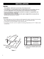
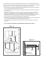
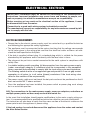
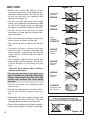
INSTALLATION and SERVICE INSTRUCTIONS
USE and CARE INSTRUCTIONS
DOMINO
VITROCERAMIC HOB
model DE302HB
distributed by
DèLonghi
Pty Ltd
Dear Customer,
Thank you for having purchased and given your preference to
our product.
The safety precautions and recommendations reported below are
for your own safety and that of others. They will also provide a
means by which to make full use of the features offered by your
appliance.
Please keep this booklet in a safe place. It may be useful in
future, either to yourself or to others in the event that doubts
should arise relating to its operation.
This appliance must be used only for the task it has explicitly
been designed for, that is for cooking foodstuffs. Any other
form of usage is to be considered as inappropriate and
therefore dangerous.
The manufacturer declines all responsibility in the event of
damage caused by improper, incorrect or illogical use of the
appliance or be faulty installation.
PRODUCT LABEL
This cooktop has been designed and constructed in accordance with the following
codes and specifications:
2
AS/NZS 60335.1
General Requirements for Domestic electrical appliances
AS/NSZ 60335.2.6 Particular Requirements for Domestic electrical cooking appliances
AS/NZS CISPR 14.1 Electromagnetic Compatibility Requirements.
BEFORE USING FOR THE FIRST TIME
• Read the instructions carefully before installing and using the appliance.
• After unpacking the appliance, make sure it is not damaged. In case of doubt, do not
use the appliance and contact your supplier or a qualified engineer.
• Remove all packaging and do not leave the packing material (plastic bags, polystyrene, bands etc) in easy reach of children as they may cause serious injury. The
packaging materials are recyclable.
• The appliance should be installed and all the electrical connections made by a qualified engineer in compliance with local regulations in force and following the manufacturer’s instructions.
• Do not attempt to modify the technical properties of the appliance, as it may become
dangerous to use.
IMPORTANT SAFEGUARDS & RECOMMENDATIONS
• Do not carry out any cleaning or maintenance without first disconnecting the appliance
from the electrical supply.
• During and after use of the hob, certain parts will become very hot. Do not touch hot
parts.
• After use always ensure that the control knobs are in the "0" OFF position.
• Household appliances are not intended to be played with by children.
• Keep children away from the hob during use.
• Children, or persons with a disability which limits their ability to use the appliance, should
have a responsible person to instruct them in its use. The instructor should be satisfied
that they can use the appliance without danger to themselves or their surroundings.
• WARNING
When correctly installed, your product meets all safety requirements laid down for this
type of product category. However special care should be taken around the underneath of the appliance as this area is not designed or intended to be touched and may
contain sharp or rough edges, that may cause injury.
• Fire Risk! Do not leave inflammable materials on the Hob top.
• Make sure that electrical cords connecting other appliances in the proximity cannot
come in to contact with the Hob top.
• Do not allow heavy or sharp objects to drop on the glass ceramic hob. If the hob is
cracked or damaged, disconnect the appliance from the electrical supply and call the
after-sales service.
• Do not scratch the hob with sharp objects. Don’t use the hob as a work surface.
• Before disposing of an unwanted appliance, it is recommended that it is made inoperative and that all potentially hazardous parts are made harmless.
• Important: This appliance has been designed for domestic use only. The appliance is
NOT suitable for use within a semi-commercial, commercial or communal environment.
• If the supply cord is damaged, it must be replaced by the manufacturer or its service agent or a similarly qualified person in order to avoid a hazard.
• Do not operate your appliance by means of an external timer or separate remote-control system.
3
INSTALLATION
CAUTION:
This appliance shall only be serviced by authorized personnel.
• This appliance is to be installed only by an authorised person according to the current local regulations and in observation of the manufacturer’s instructions.
• Incorrect installation, for which the manufacturer accepts no responsibility, may
cause personal injury of damage.
• Always disconnect the cooktop from mains power supply before carrying out any
maintenance operations or repairs.
WARNING !
• We would point out that the adhesive which bonds the plastic laminate to the furniture
must withstand temperatures not less than 150 °C to avoid delamination.
• The appliance must be housed in heat resistant units.
• The walls of the units must be capable of resisting temperatures of 75 °C above room
temperature.
300
0
45,2 mm
from the top of
countertop to bottom
metal cover
63,5 mm
from the top of
countertop to
terminal block
50
(1)
51
49
0
A
A
(1): at least 50 mm between the back side
of the cut-out and the back of the
countertop.
270
Figure 1
4
This cooktop can be built into a working surface 20 to 40 mm thick and 600 mm deep.
In order to install the ceramic hob into the kitchen fixture, a hole with the dimensions
shown in figure 1 has to be made, keeping in consideration the following:
• Within the unit, between the bottom of the hob and the upper surface of a shelf there
must be a clearance of at least 30 mm (fig. 2b).
• It is absolutely essential that you place a separator between the base of the hob and
the built-in unit.
• If the hob is installed over a built-in oven, there must be a distance of at least 30 mm
between the two appliances. The oven shall be provided with cooling fan. The two
appliances should be connected to the electrical supply with independent connections.
• The ceramic hob must be kept no less than 50 mm away from any side wall.
• The rear wall must be at least 50 mm from the ceramic hob.
• There must be a distance of at least 650 mm between the hob and any wall cupboard
or extractor hood positioned immediately above (see fig. 2a).
• The coatings of the walls of the unit or appliances near the cooktop must be heat
resistant.
• Do not install the appliance near inflammable materials (eg. curtains).
650 mm
450 mm
Figure 2a
Figure 2b
500 m
Clearance
Separator
50 mm minimum between the side
of the cut-out and the side wall
30 mm
m
Space for
connections
5
FASTENING THE COOKTOP
Each cooktop is supplied with a set of tabs and screws to fasten it on units with a working surface from 2 to 4 cm deep.
The kit includes 4 tabs A and 4 self-threading screws B (fig. 4).
•
•
•
•
•
•
•
•
Cut the unit.
Turn the hob upside down and rest the glass side on a cloth.
Spread the seal C around the edge of the hob (fig. 3).
Put tabs A into the mountings; only tighten screws B a few turns.
Make sure that the tabs are mounted correctly as shown in the figure 4.
Put the cooktop into the hole cut into the unit and position it correctly.
Put tabs A into place, tooth D of the tabs should go into the hole.
Tighten screws B until the cooktop is completely secured.
Using a sharp tool cut off the part of gasket C which protrudes from the cooktop. Take
care not to damage the workbench.
Figure 4
C
Figure 3
A
A
C
C
6
Adhesive side
A
40 mm max.
B
20 mm min.
D
ELECTRICAL SECTION
IMPORTANT: Installation must be carried out according to the manufacturer's
instructions. Incorrect installation may cause harm and damage to people, animals or property, for which the manufacturer accepts no responsibility.
Before carrying out any work on the electrical section of the appliance, it must
be disconnected from the mains.
Connection to a good earth wiring system is absolutely essential.
The manufacturer accepts no responsibility for any inconvenience caused by failure to comply with this rule.
ELECTRICAL REQUIREMENTS
• Connection to the electric power supply must be carried out by a qualified technician
and following the appropriate safety regulations.
• The appliance must be connected to the mains checking that the voltage corresponds
to the value given in the rating plate and that the electrical cable sections can withstand the load specified on the plate.
• If the hob is supplied without plug, fit a standard plug which is suitable for the power
absorbed by the appliance and in conformity with the local rules in force.
• The plug must be put into a socket connected to the earth system in compliance with
safety rules.
• A suitable isolating switch providing full disconnection from the mains power supply
(under overvoltage category III conditions) shall be incorporated in the permanent
wiring, mounted and positioned to comply with the local wiring rules and regulations.
The isolating switch must be of an approved type and provide a 3 mm air gap contact
separation in all poles (or in all active [phase] conductors if the local wiring rules
allow for this variation of the requirements).
• The power supply cable must not touch the hot parts and must be positioned so that it
does not exceed 50°C above ambient.
• Once the appliance has been installed, the power switch or power plug must always
be in a accessible position.
N.B. For connections to the mains power supply, never use adaptors, reductions or
multiple power points as these may overheat and catch fire.
In the event that installation should require modifications to the mains supply wiring system, it is recommended that a qualified technician be called to carry out substitution.
The technician will also have to verify that the cross-section of the electric cables on the
power point match the appliance’s power rating.
If the hob surface is cracked disconnect the appliance from the mains and contact
the After-Sales Service.
7
Figure 5
REPAIRS
Replacing the supply cable
Turn the cooktop over and unhook the
terminal board cover by inserting a
screwdriver into the two hooks “A”.
A
Open the cable gland by unscrewing
screw “F”, unscrew the terminal screws
and remove the cable.
The new supply cable, of suitable type
and section, is connected to the terminal board following the diagrams
shown below.
SECTION OF THE SUPPLY
CABLE
Figure 6
Use H05RR-F cables
220-240 V ~, 50/60 Hz, 2900 W (12.6 A)
F
section: 3 x 1,5 mm2
Figure 7
220-240 V
E
N
L
WARNING: If the power supply cable
is damaged, it must be replaced only
by an authorised service agent in
order to avoid a hazard.
8
L
N
E
Earth
Neutral
Live
ELECTRIC DIAGRAM
Figure 8
4
4A
S H
2
4
P2
2 S
H
P1
On
S2
Hot
S1
F1
F2
(PHASE)
532008
INVENSYS
MP-101-FPC
(LOAD)
L
N
(N)
M
(PILOT)
(PHASE)
(LOAD1)
532009
INVENSYS
MDP-110-FPC
(N)
(LOAD2) (PILOT)
ELECTRIC DIAGRAM KEY
F1
F2
S2
S1
P1/P2
M
T
Radiant heater energy regulators
Radiant heater energy regulators
Line pilot lamp
Radiant heaters pilot lamp
Radiant heaters
Terminal block
Earth connection
9
VITROCERAMIC HOB
Figure 9
2
1
MIN
MAX
MIN
6 5
MAX
MIN
MAX
4
3
FEATURES
- Electrical insulation Class I.
GENERAL FEATURES
1. Hi-light cooking zone Ø 140 mm - 1200 W
2. Double hi-light cooking zone Ø 180/120 mm - 1700/700 W
CONTROL PANEL DESCRIPTION
3.
4.
5.
6.
10
Hotplate 1 control knob
Hotplate 2 control knob
Residual heat indicator light
Power ON indicator light
How to use your Ceramic Hob
The ceramic surface of the hob allows a fast transmission of heat in the vertical direction, from the heating elements underneath the ceramic glass to the pans set on it.
The heat does not spread in a horizontal direction, so that the glass stays “cool” at only
a few centimeters from the cooking plate.
The cooking zones are shown by painted disks on the ceramic surface.
Before switching on the cooktop make sure that it is clean.
IMPORTANT NOTE:
The heating elements incorporate a thermolimiter that switches the element ON/OFF
during all settings to protect the ceramic glass from overheating.
The use of incorrect pans and/or wrong pan positioning will cause the temperature limiter to operate more frequently, resulting in a reduction of cooking performance.
The temperature limiter can be seen under the glass dissecting the element.
This is not a fault with the appliance.
HI-LIGHT SINGLE ZONE (fig.10)
The heating element is formed of a coil
of resistant material which reaches the
working temperature quickly.
This zone is controlled by a continuous
energy regulator switch (fig. 11).
The heat intensity can be regulated continuously from “MIN” to “MAX”.
Check that the hob is clean and then
switch on by turning the control knob.
When the hob is working, the pilot light
will be on.
Figure 10
Hi-light single cooking zone
Figure 11
MAX
MIN
11
HI-LIGHT DOUBLE ZONE (fig. 12)
The heating element is formed of a 2 coils of resistant material which reaches the working temperature quickly.
These zones are controlled by a continuous energy regulator switch (fig. 13).
You may choose to use the inner zone only ( ) or the fual dual cooking zone ( ).
The heat intensity can be regulated continuously from “MIN” to “MAX”.
Check that the hob is clean and then switch on by turning the control knob.
When the hob is working, the pilot light
will be on.
MIN
Inner zone
Full dual zone
MAX
MIN
Second element
MAX
MIN
MAX
Hi-light
double
zone
MIN
12
Figure 12
MAX
Figure 13
RESIDUAL HEAT INDICATOR
The hob also features a warning lamp which
is wired to the cooking zones.
When the temperature of a cooking plate is
over 60°C, the warning lamp is also lit-up to warn
of heat on the surface of the hob.
This lamp also stays on after the cooking
plates have been switched off to shown that
the hob surface is still hot.
This residual heat will lasts for a long time after
the cooking plate has been switched off.
Figure 14
During this time you should avoid
touching the hob surface over the
cooking area.
Please pay special attention to ensure
that children are not allowed near the
hob.
Fig. 2.6
The lamp will switch off automatically as soon
as the surface temperature of the cooking zone
falls below 60°C.
COOKING HINTS
– To reduce the cooking time, you can turn the control knob to the max when you
switch the plate on. After a short time you will set the control knob to the required
position for the cooking.
– You should use pots and pans with flat bases (pans with the test mark for glassceramic hobs are available from specialist shops).
– The diameter of the pan should match that of the cooking plate (or be slightly bigger)
to make the most of the energy.
– Since the cooking surface stays hot for a certain time after the plate has been
switched off, you can switch it off 5 or 10 minutes before the end of the cooking.
The residual heat of the hob will complete the cooking.
– To save electricity, use pan lids whenever possible.
Never cook the food directly on the glass ceramic cooktop, but in special pans
or containers.
WARNING: Hobs become very hot with use, and retain their heat for a long time
after cooking has finished (about 30 minutes).
Children should be supervised at all times and be prevented from touching the
hot surfaces, until such time as the appliance has cooled.
13
SAFETY HINTS
• Before you switch the hob on, make
knob controls
sure you know which touch
controlsthe
the
required cooking zone. We advise you
to set the pan over the cooking zone
before switching it on.
• Do not use pots and pans with rough
bases (pay attention to cookware made
of cast-iron). Rough bases can damage
the glass surface of the hob (scratches).
• Always ensure that the base of your
saucepan is clean and dry before placing on the hob.
• Pots with aluminium bottoms may leave
silver streaks or spots on the hob.
• Do not leave wet or damp lids on the
hob.
• The glass-ceramic surface and pans
must be clean. Carefully eliminate any
food remains (especially containing
sugar), dirt etc. with the aid of a cleansing agent.
• Pan handles should never stand out
beyond the kitchen worktop, as there is
a great danger of knocking the pan
over.
This will also ensure that children
cannot reach them.
Figure 15
DISTORTED
PANBASE
WRONG
DISTORTED
PANBASE
WRONG
LEVEL
PANBASE
CORRECT
WRONG
WASTING
POWER
WRONG
WASTING
POWER
• Do not use the hob if the glass surface is broken or cracked in any way.
Please disconnect the hob from the
mains and contact the after-sales
service.
WRONG
• Do not lean over the cooking plate
when in use.
CORRECT
• Do not lay cooking foil or plastic materials on the ceramic surface when it is
hot.
• Remember that the surface remains hot
for a long time (about 30 min.) after the
cooking plate has been switched off.
WASTING
POWER
COMPLETE USE
OF THE HEAT
Fig. 2.4
DO NOT USE GLASSWARE ON CERAMIC HOBS.
DO NOT USE PANS WITH ROUGH CIRCULAR MACHINED BASE.
• Follow the cleaning instructions carefully.
• Never use the glass surface for storage.
14
Figure 16
Cleaning and Maintenance
Before you begin cleaning make sure that the hob is switched off.
• Remove spillages and other types of incrustations.
• Dust or food particles can be removed with a damp cloth.
• If you use a detergent, please make sure that it is not abrasive or scouring. Abrasive
or scouring powders can damage the glass surface of the hob.
• All traces of the cleaner must be removed with a damp cloth.
• Dust, fat and liquids from food that has boiled over must be removed as soon as possible.
• If they are allowed to harden they become increasingly difficult to remove.
This is especially true in the case of sugar/syrup mixtures which could permanently pit the surface of the hob if left to burn on it.
• If any of these products has melted on the ceramic surface, you should remove it
immediately (when the surface is still hot) by using a scraper to avoid any permanent
damage to the surface of the hob (available under part no. 103138).
• Do not put articles on the hob which can melt: i.e plastic, aluminium foil, sugar, sugar
syrup mixtures etc.
• Avoid using a knife or other sharp utensil as these may damage the ceramic surface.
• Do not use steel wool or an abrasive sponge which could scratch the surface permanently.
• Do not use cleaning products with a chlorine or acidic base.
SIDE STAINLESS STEEL TRIMS
• Stainless steel parts must be rinsed with water and dried with a soft and clean cloth.
• For persistent dirt, use specific non-abrasive products available commercially or a little hot vinegar.
CONTROL KNOBS
CONTROL
KNOBS
• The control knobs
may be removed
for cleaning
caremay
should
be taken
• The
control but
knobs
be removed
not cleaning
to damage
seal.
for
butthe
care
should be taken
not to damage the seal.
Do not use harsh abrasive cleaners
or sharp metal scrapers to clean the
glass since they can scratch the
s u r face , whic h m ay re s u lt in
shattering of the glass.
Do not use a steam cleaner because
the moisture can get into the appliance thus make it unsafe.
Figure 17
15
Descriptions and illustrations in this booklet are given as simply indicative. The manufacturer reserves the right,
considering the characteristics of the models described here, at any time and without notice, to make eventual
necessary modifications for their construction or for commercial needs.
cod. 1103769 - ß1