1
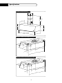
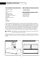
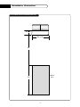
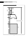
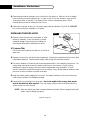
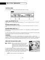
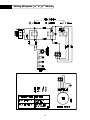
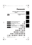
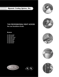
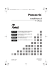
Dynamic Cooking Systems, Inc.
THE PROFESSIONAL EURO HOOD
Use and Installation Guide
Models:
■ EH-30SS
■ EH-36SS
A Message To Our Customers
Thank you for selecting this DCS Updraft Euro Hood. Because of its unique features, we have developed this
Use and Installation Guide. It contains valuable information on how to properly operate and maintain your new
Updraft Euro Hood for years of safe and enjoyable cooking.
To help serve you better, please fill out and return the Ownership Registration Card and keep this guide handy,
as it will help answer questions that may arise as you use your Updraft Euro Hood.
For your convenience, product questions can be answered by a DCS Customer Service
Representative by phone: 1-888-281-5698, or Fax: 714-372-7003,
or by mail:
DCS
Attention Customer Service,
5800 Skylab Road, Huntington Beach, CA 92647
WARNING
TO REDUCE THE RISK OF A RANGE TOP GREASE FIRE:
Never leave surface units unattended at high settings. Boilovers cause smoking and greasy spillovers that may
ignite. Heat oils slowly on low or medium setting. Always turn the euro hood “ON” when cooking at high heat or
when cooking flaming foods. Clean ventilating fans frequently. Grease should not be allowed to accumulate on
fan or filter. Use proper pan size. Always use cookware appropriate for the size of the surface element.
WARNING
TO REDUCE THE RISK OF INJURY TO PERSONS IN THE EVENT OF A RANGE TOP GREASE FIRE, OBSERVE
THE FOLLOWING: SMOTHER FLAMES with a close-fitting lid, cookie sheet, or metal tray, then turn off the
burner. BE CAREFUL TO PREVENT BURNS. If the flames do not go out immediately EVACUATE AND CALL
THE FIRE DEPARTMENT. NEVER PICK UP A FLAMING PAN - You may be burned. DO NOT USE WATER,
including wet dishcloths or towels - a violent steam explosion will result. Use an extinguisher ONLY if:
1.You know you have a Class ABC extinguisher, and you already know how to operate it.
2.The fire is small and contained in the area where it started.
3.The fire department is being called.
4.You can fight the fire with your back to an exit.
PLEASE RETAIN THIS MANUAL
FOR FUTURE REFERENCE.
1
Table Of Contents
SAFETY PRACTICES & PRECAUTIONS...............................................................................3
SPECIFICATIONS ..................................................................................................................................4
PLANNING THE INSTALLATION ..............................................................................................5
INSTALLATION INSTRUCTIONS........................................................................................6-11
Tools Needed ...................................................................................................................................6
Standard Installation Dimensions ................................................................................................7
Ceiling Height Variances.................................................................................................................8
Calculate Duct Run Length...........................................................................................................9
Wall Preparation........................................................................................................................9-10
Installing Euro Hood...............................................................................................................10-11
Optional Ductless Installation Kits ...........................................................................................11
USE AND CARE ....................................................................................................................................12
WIRING DIAGRAM ............................................................................................................................13
HOW TO OBTAIN SERVICE ........................................................................................................14
WARRANTY ............................................................................................................................................15
2
Safety Practices & Precautions
This euro hood system is designed to remove smoke, cooking vapors and odors from the cooktop
area.
WARNING: ALL WALL AND FLOOR OPENINGS WHERE THE EURO HOOD IS INSTALLED MUST
BE SEALED.
Consult the cooktop or range installation instructions given by the manufacturer before making any
cutouts. MOBILE HOME INSTALLATION- The installation of this euro hood must conform to the
Manufactured Home Construction and Safety Standards,Title 24 CFR, Part 3280 (formerly Federal
Standard for Mobile Home Construction and Safety,Title 24, HUD, Part 280). Four wire power supply
must be used and the appliance wiring must be revised. See Electrical Requirements.
•
•
•
•
•
•
•
•
Venting system MUST terminate outside the home.
DO NOT terminate the ductwork in an attic or other enclosed space.
DO NOT use 4" laundry-type wall caps.
Flexible-type ductwork is not recommended.
DO NOT obstruct the flow of combustion and ventilation air.
Failure to follow venting requirements may result in a fire.
Electrical ground is required on this euro hood.
If cold water pipe is interrupted by plastic, non-metallic gaskets or other materials, DO NOT use for
grounding.
• DO NOT ground to a gas pipe.
• DO NOT have a fuse in the neutral or grounding circuit. A fuse in the neutral or grounding circuit
could result in electrical shock.
• Check with a qualified electrician if you are in doubt as to whether the euro hood is properly
grounded.
• Failure to follow electrical requirements may result in a fire.
WARNING: TO REDUCE THE RISK OF FIRE, ELECTRICAL SHOCK, OR INJURY TO PERSONS,
OBSERVE THE FOLLOWING:
Use this unit only in the manner intended by the manufacturer. If you have any questions, contact the
manufacturer. Before servicing or cleaning unit, switch power off at service panel and lock the service
disconnecting means to prevent power from being switched on accidentally. When the service disconnecting means cannot be locked, securely fasten a prominent warning device, such as a tag, to the
service panel. Installation Work And Electrical Wiring Must Be Done By Qualified Person(s) In
Accordance With All Applicable Codes And Standards, Including Fire-Rated Construction. Sufficient air
is needed for proper combustion and exhausting of gases through the flue (chimney) of fuel burning
equipment to prevent backdrafting. Follow the heating equipment manufacturer's guideline and safety
standards such as those published by the National Fire Protection Association (NFPA), and the
American Society for Heating, Refrigeration and Air Conditioning Engineers (ASHRAE), and the local
code authorities. When cutting or drilling into wall or ceiling, do not damage electrical wiring and
other hidden utilities.
NOTE: Ducted fans must always be vented to the outdoors.
3
Specifications
FIG.01Hood with optional Chimney
7 1/2" 8 3/4"
20 7/8"
min.
to
40" max.
14 7/8"
9 7/16"
10 5/16"
29 7/8" - 30" Hood
35 7/8" - 36" Hood
19 1/2"
FIG.02a Duct / Bracket / Electrical Dimensions 30” Hood
5 7/8"
11/16"
4"
4 5/16"
"
12 5/8
"
9 7/8
"
2 15/16
"
25 1/4
FIG.02b Duct / Bracket / Electrical Dimensions 36” Hood
5 7/8"
11/16"
4"
4 5/16"
"
15 5/8
"
9 7/8
"
2 15/16
"
31 1/4
4
Planning The Installation
VENTING REQUIREMENTS
Determine which venting method is best for your application. Ductwork can extend either through
the wall or the roof. The length of the ductwork and the number of elbows should be kept to a minimum to provide efficient performance. The size of the ductwork should be uniform. Do not install
two elbows together. Use duct tape to seal all joints in the ductwork system. Use caulking to seal
exterior wall or floor opening around the cap. Flexible ductwork is not recommended. If it is used,
each foot of flexible ductwork used is equivalent to two feet of straight metal ductwork when calculating the duct run length. Thus, a flexible elbow equals two standard elbows. Make sure there is proper
clearance within the wall or floor for exhaust duct before making cutouts. Do not cut a joist or stud
unless absolutely necessary. If a joist or stud must be cut, then a supporting frame must be
constructed.
WARNING: TO REDUCE THE RISK OF FIRE, USE ONLY METAL DUCTWORK.
ELECTRICAL REQUIREMENTS
A 120 volt, 60 Hz AC-only electrical supply is required on a separate 15 amp circuit, fused on both
sides of the line. A time-delay fuse or circuit breaker is recommended. The fuse must be sized per
local codes in accordance with the electrical rating of this unit as specified on the serial/rating plate
located inside the unit near the field wiring compartment.
THIS UNIT MUST BE CONNECTED WITH COPPER WIRE ONLY. Wire sizes must conform to the requirements of the National Electrical Code, ANSI/NFPA 70 -latest edition, and all local codes and ordinances.
Wire size and connections must conform with the rating of the appliance. This appliance should be
connected directly to the fuse disconnect (or circuit breaker) through flexible, armored or non-metallic
sheathed copper cable. Allow some slack in the cable so the appliance can be moved if servicing is
ever necessary. A UL Listed, 1/2" conduit connector must be provided at each end of the power supply
cable (at the appliance and at the junction box). When making the electrical connection, cut a 1 1/4"
hole in the wall. A hole cut through wood must be sanded until smooth. A hole through metal must
have a grommet.
WARNING: To reduce the risk of fire or electric shock, DO NOT use this fan with any solid state speed
control device.
CAUTION: For General Ventilating Use Only. Do Not Use To Exhaust Hazardous or Explosive
Materials and Vapors.
5
Installation Instructions
TOOLS NEEDED FOR INSTALLATION
PARTS SUPPLIED FOR INSTALLATION
• Saber Saw or Jig Saw
• Drill
• 1 1/4 Wood Drill Bit
• Pliers
• Phillips Screwdriver
• Flat Blade Screwdriver
• Wire Stripper or Utility Knife
• Metal Snips
• Measuring Tape or Ruler
• Level
• Pencil
• Caulking Gun
• Duct Tape
• 1 Hardware Package
• 1 Literature Package
PARTS NEEDED FOR INSTALLATION
• 2 Conduit Connectors
• Power Supply Cable
• 1 Wall or Roof Cap
• All Metal Ductwork
This euro hood can be installed with (Fig. 03) or without (Fig. 04) an optional telescopic chimney kit
(model #ECD-2SS). In a ducted application, this euro hood can be vented through the wall or ceiling.
To vent through a wall, a 900 elbow is used. When installing ductless with a chimney kit, the euro hood
vents out of grates on the sides of the ductless chimney kit (model #ECND-2SS). This ductless installation also requires a charcoal filter kit (model #ECF). When installing ductless without the optional
chimney kit, some ductwork must be installed to divert the air out of the cabinet. This installation
requires charcoal filter kit (model #ECF). See page 11 for more details on all ductless installations.
WARNING: Before making any cuts or holes for installation. Determine which venting method will be
used and carefully calculate all measurements.
Standard installation for the euro hood requires the canopy to be mounted 30” above the countertop
(Fig. 05a). The optional telescopic chimney kit can be adjusted for ceilings between eight 8’ 2” and 9’ 8”
(Fig 05b).
FIG.04 EURO HOOD WITHOUT OPTIONAL CHIMNEY
FIG.03 EURO HOOD WITH OPTIONAL CHIMNEY
6
Installation Instructions
FIG.05A STANDARD INSTALLATION DIMENSIONS (FRONT VIEW)
10 5/16"
30" or 36"
30"
cabinet
base
36"
7
Installation Instructions
FIG.05B CEILING HEIGHT VARIANCES WITH OPTIONAL CHIMNEY KIT (SIDE VIEW)
Upper
Chimney
Cover
min 21 7/8"
max 40"
Lower
Chimney
Cover
10 5/16"
19 1/2"
30"
Max. = 9' 8 5/16" (116 5/16")
Min. = 8' 2 3/16" (98 3/16")
cabinet
base
36"
8
Installation Instructions
CALCULATE THE DUCT RUN LENGTH
The duct run should not exceed 35 feet if ducted six inch (6”) round ductwork. Calculate the length
of the ductwork by adding the equivalent feet in fig. 06 for each piece of duct in the system an example
is given in fig. 07. For best results, use no more than three 900 elbows. Make sure that there is a
minimum of 24” of straight duct between elbows if more than one is used. Do not install two
elbows together.
FIG.06
FIG.07
45° Elbow =
90° Elbow =
90° Flat Elbow
Wall Cap
9 Feet Straight Duct
2 - 90° Elbows =
Wall Cap
Total System =
5.0 feet
7.0 feet
12.0 feet
0.0 feet
9.0 feet
14.0 feet
0.0 feet
23.0 feet
WARNING: Personal injury hazard due to the weight and size of the euro hood canopy, two or
more people are needed to move and safely install the euro hood canopy. Failure to
properly lift euro hood could result in damage to the product or personal injury.
WALL PREPARATION
WARNING: The screws provided for mounting this euro hood must be inserted into solid wood. These
must not be inserted into sheet rock.
1) Disconnect and move freestanding range from cabinet opening to provide easier access to upper
cabinet and rear wall. Put a thick, protective covering over cooktop, set-in range or countertop to
protect from damage or dirt.
2) Determine and clearly mark with a pencil the centerline on the wall where the euro hood will be
installed.
3) The euro hood attaches to the wall by mounting screws. For the 30" and 36" models, there are two
mounting screws. Install the screws into the wall. The screws should be inserted into the wall
until the screw head is flush with the wall.
4) The optional chimney kit is adjustable and designed to meet varying ceiling heights. The chimney
attaches to the wall by two additional brackets. The top bracket should be installed about 1/8”
away from the ceiling. The middle bracket must be installed at the bottom point of the upper
chimney sleeve. Determine the proper location for each bracket and install the brackets on the
wall. Attach the bottom of the lower chimney to the canopy using the screws provided.
CAUTION: Make sure that the screws and brackets are securely fastened to the wall.
9
Installation Instructions
5) Determine and make all necessary cuts in the wall for the ductwork. Each euro hood is shipped
from the factory vented through the top. In order to vent to the rear, ductwork must run first
vertical then elbow to the back. The dimensions for the duct openings are given in Fig. 02.
Install all ductwork before installing the euro hood.
6) Determine the proper location for the power supply cable as indicated in Fig. 2a & 2b. DO NOT
turn on the power until installation is complete.
INSTALLING THE EURO HOOD
FIG.08
1) Remove the unit from the carton and place on a flat
surface for assembly. Cover the surface to prevent
accidental damage. Remove all parts including the
mounting hardware before discarding the carton.
2) To remove filter:
Pull knob forward (towards you) and turn to the left at
same time.
3) Remove the cover from the field wiring compartment. Remove the wiring electrical knockout using
a flat-blade screwdriver. Feed the power supply cable through the electrical knockout.
4) The canopy attaches to the wall by two screws discussed earlier in the installation instructions. The
canopy hangs from these screws by brackets inside the euro hood shown in Fig. 08. Before
attempting to hang the canopy, you should rotate the adjustment screw marked V1 in Fig. 08
counter clockwise to extend the brackets from the canopy. Using a Phillips head screwdriver, rotate
this screw counter clockwise to extend the bracket.
5) Install the damper before hanging the euro hood. The damper attaches to the euro hood by two
small screws provided in the hardware package.
6) Hang the euro hood canopy from the screws. Due to the weight of the canopy, these screws
must be installed into solid material! Once the canopy is hung, rotate the screw marked V1 to
secure the euro hood to the wall.
NOTE: Make sure that the euro hood is securely attached to the wall! Failure to properly install could
result in injury or damage to property.
(continued on page 11)
10
Installation Instructions
7) The brackets shown in Fig. 08 are also used to adjust the level of the canopy. Using a Phillips
screwdriver, rotate the screw V2 to adjust the level of the canopy.
8) Connect the Power Supply Cable to the euro hood. Attach the White lead of the power supply to
the White lead of the euro hood with a twist-on type wire connector. Attach the Black lead of
the power supply to the Black lead of the euro hood with a twist-on type wire connector.
Connect the Green ( Green and Yellow ) ground wire under the Green grounding screw.
9) Replace the field wiring compartment cover and the grease filters.
To install grease filter: Put the end of grease filter without the knob into the channel in the
front of hood. Turn knob to the left so the lever does not protrude from filter. Insert knob end of
grease filter into the channel in the back of the hood. Turn knob to the right, locking filter in place.
10)Turn the power supply on.Turn on blower and light. The euro hood controls are located on the
right-hand side under the canopy. If the euro hood does not operate, check that the circuit breaker
is not tripped or the house fuse blown If the unit still does not operate, disconnect the power
supply and check that the wiring connections have been made properly.
DUCTLESS INSTALLATION KITS
FIG.09
The euro hood can be installed ductless in both chimney and no
chimney (under cabinet) installation. To install ductless in a chimney
installation, you must have the ductless chimney kit (model #ECND2SS) fig. 09 and the charcoal filter kit (model #ECF) fig. 11. To install
ductless in a no chimney installation (under cabinet) fig. 10 you must
have the charcoal filter kit fig. 11.
The ductless chimney kit consists of an upper chimney (not pictured),
a lower chimney ( A) with two holes for the exhaust air, a ductless
diverter (B) which sits on the canopy of the hood and diverts the air
to the sides of the chimney, and two vent grates (C) to cover the
holes in the lower chimney.
A
B
C
FIG.10
The charcoal filter kit contains two charcoal filters which twist onto
either side of the blower inside the euro hood.
When installing ductless without the optional chimney kit, some
ductwork must be installed to divert the air either out of the top of
the cabinet or to the face of the soffit. The duct work can not
terminate inside the cabinet or into any dead air space.
11
FIG.11
Use & Care Information
CONTROL PANEL
The control panel is located on the right-hand side under the canopy.
FIG.12
LIGHT ON/OFF SWITCH ( A )
On/Off switch for the halogen light. Move the switch to "1" to turn the light ON and to "0" to turn it
OFF.
BLOWER ON/OFF SWITCH ( B )
On/Off switch for the blower. Move the switch to "1" to turn the blower ON and to "0" to turn it
OFF.
BLOWER SPEED SWITCH ( C )
Speed control for blower. Move the switch to position 1 for LOW Speed, 2 for MEDIUM speed and 3
for HIGH speed.
For Best Results Start the euro hood before cooking and allow the unit to operate for several minutes
after cooking is complete to clear all smoke and odors from the kitchen.
CLEANING
The metal grease filters should be cleaned frequently in hot detergent solution or washed in the
dishwasher. Clean exterior surfaces with a commercially available stainless steel cleaner. Abrasives and
scouring agents can scratch stainless steel finishes and should not be used to clean finished surfaces.
REPLACING THE HALOGEN LAMPS
FIG.13
WARNING: Before you begin, make sure that the euro hood is
turned off and that the other lamps have had
sufficient time to cool. Halogen bulbs burn extremely
hot and serious injury could result from touching a hot
bulb.
To replace the lamp, the bezel (A) around the lamp(C) must be
removed. The bezel (A) is held in place by two screws (B). Remove
the two screws and the bezel.Then remove the lamp and replace with
a new lamp. Once the new lamp is in place, reinstall the bezel.
NOTE: This euro hood uses 20 watt Halogen Lamps.
12
Wiring Diagram 30” & 36” Hoods
13
Service
HOW TO OBTAIN SERVICE:
Before you call for service:
1) Is the circuit breaker tripped or the fuse blown?
2) Is there a power outage in the area?
For warranty service, contact your local DCS authorized service agency. Provide service agency with
the Model Number, Serial Number, and date of installation, and a brief description of the problem. If
you need assistance in locating the authorized service agency in your area please contact our DCS
Consumer Service Department for an authorized service agent near you, our number is
(888) 281-5698.
Your satisfaction is of the utmost importance to us. If a problem cannot be resolved to your
satisfaction, please write or fax us at:
Write:
DCS
Attention: Consumer Relations
5800 Skylab Road Huntington Beach, CA 92647
Fax us at: (714) 372-7003
14
Warranty
LENGTH OF WARRANTY
One (1) Year Full parts and Labor Covers the entire product
Five (5) Year Limited warranty covering the switches and motor.
DCS WILL PAY FOR
All repair labor and parts found to be defective due to materials or workmanship for one full year “IN HOME”
warranty during the first year of ownership. This does not apply if the unit was subjected to other than normal
household use. Service must be provided by Authorized Factory Agent during normal working hours. No charges
will be made for repair or replacement at the location of initial installation or factory for parts returned pre-paid,
through the dealer and claimed within the warranty period, and found by DCS to be defective.
Replacement will be F.O.B. DCS, and DCS will not be liable for any transportation costs, labor costs, or export
duties. This warranty shall not apply, nor can we assume responsibility for damage that might result from failure
to follow manufactures instructions or local codes, where the appliance has been tampered with or altered in
anyway or which, in our judgement, has been subjected to misuse, negligence, or accident. Implied warranty shall
not extend beyond the duration of this written warranty.This warranty is in lieu of all warranties expressed or
implied and all other obligations or liability in connection with the sale of this appliance.
DCS WILL NOT PAY FOR
zInstallation
or start-up.
damage.
zService by an unauthorized agency.
zDamage or repairs due to service by an unauthorized agency or the use of unauthorized parts.
zService during other than normal working hours.
zImproper installation, such as improper hook-up, etc.
zService visits to teach you how to use the appliance; correct the installation; reset circuit breakers or replace
home fuses.
zRepairs due to other than normal household use.
zDamage caused from accident, abuse, alteration, misuse, incorrect installation or installation not in accordance
with local codes.
zUnits installed in non-residential application such as day care centers, bed and breakfast centers, churches,
nursing homes, restaurants, hotels, schools, etc.
zShipping
This warranty applies to appliances used in residential applications; it does not cover their use in commercial
situations. This warranty is for products purchased and retained in the 50 states of the U.S.A., the District of
Columbia and Canada.This warranty applies even if you should move during the warranty period. Should the
appliance be sold by the original purchaser during the warranty period, the new owner continues to be protected
until the expiration date of the original purchaser’s warranty period. This warranty gives you specific legal rights.
You may also have other rights which vary from state to state.
15
Notes
16
As product improvement is an ongoing
process at DCS, we reserve the right to
change specifications or design without
notice.
5800 Skylab Road, Huntington Beach, CA. 92647 Tel: (714) 372-7000
Fax: (714) 372-7001 Parts/Customer Service (888) 281-5698
www.dcsappliances.com
Part No. 17386 Rev. A
Litho in USA 06/2001