1
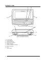
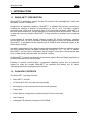
Rhino-NET
TM
www.mobile.datalogic.com
World wide Sales Network
available from: www.mobile.datalogic.com/contacts
Datalogic Mobile S.r.l.
Via S. Vitalino, 13
40012 Lippo di Calderara di Reno
Bologna - Italy
Telephone: (+39) 051-3147011
Fax: (+39) 051-3147561
©2008 Datalogic Mobile S.r.l.
822000494 (Rev. E)
User’s Manual
07/08
Datalogic Mobile S.r.l.
Via S. Vitalino 13
40012 – Lippo di Calderara di Reno
Bologna – Italy
Rhino-NET™ – User's Manual
Ed.: 07/2008
ALL RIGHTS RESERVED
Datalogic is a registered trademark of Datalogic S.p.A. in many countries and the Datalogic logo is a trademark of
Datalogic S.p.A.. All other brand and product names mentioned herein are for identification purposes only and
may be trademarks or registered trademarks of their respective owners.
Datalogic reserves the right to make modifications and improvements without prior notification.
Datalogic shall not be liable for technical or editorial errors or omissions contained herein, nor for incidental or
consequential damages resulting from the use of this material.
© Datalogic Mobile S.r.l. 2000-2008
CONTENTS
REFERENCES ............................................................................................................. v
Conventions.................................................................................................................. v
Reference Documentation ............................................................................................ v
Services and Support ................................................................................................... v
SAFETY REGULATIONS ........................................................................................... vi
FCC Compliance ......................................................................................................... vi
Radio Compliance .......................................................................................................vii
Vehicle Power Supply Connection Safety Statement .................................................viii
AC Power Supply Safety Statement ............................................................................ ix
Bluetooth® Approval.................................................................................................... ix
WEEE Compliance ....................................................................................................... x
GENERAL VIEW ........................................................................................................ xii
QUICK START .......................................................................................................... xiii
1
1.1
1.2
1.3
1.4
1.5
1.6
1.7
1.7.1
1.8
1.9
INTRODUCTION .......................................................................................................... 1
Rhino-NET™ Description ............................................................................................. 1
Package Contents ........................................................................................................ 1
Available Models........................................................................................................... 2
The Display................................................................................................................... 2
Keyboard ...................................................................................................................... 2
PCMCIA Slots............................................................................................................... 2
Power Supply................................................................................................................ 3
Backup Batteries........................................................................................................... 3
Bluetooth® Module ....................................................................................................... 4
Connectors ................................................................................................................... 4
2
2.1
2.2
2.3
2.4
2.5
2.6
2.6.1
2.7
2.8
INSTALLATION ........................................................................................................... 5
Required Mounting Material.......................................................................................... 5
Mounting to Forklift Roof............................................................................................... 5
Mounting to Forklift Floor .............................................................................................. 7
Positioning .................................................................................................................... 8
Connecting Power ...................................................................................................... 10
Connecting a Serial Barcode Scanner........................................................................ 13
Laser Barcode Scanner Warnings.............................................................................. 14
Connecting a Serial Mouse......................................................................................... 14
Connecting a Serial Device ........................................................................................ 15
3
3.1
3.2
3.2.1
3.2.2
3.3
3.3.1
3.3.2
3.4
3.5
3.5.1
USE AND OPERATION ............................................................................................. 16
Powering On/Off ......................................................................................................... 16
Key Descriptions......................................................................................................... 17
Control Keys ............................................................................................................... 17
Keyboard LEDs........................................................................................................... 18
Reset (Reboot) ........................................................................................................... 18
Hardware Reset.......................................................................................................... 19
Software Reset ........................................................................................................... 19
Battery Warning Messages......................................................................................... 19
Control Panel .............................................................................................................. 20
Registry Admin ........................................................................................................... 20
iii
3.5.2
3.5.3
3.5.4
3.6
3.7
3.8
3.8.1
3.8.2
3.9
Files Admin ................................................................................................................. 21
Scanner Setup ............................................................................................................ 22
Bluetooth Manager Device Setup ............................................................................... 25
Barcode Reading ........................................................................................................ 26
Remote Display .......................................................................................................... 26
Microsoft® ActiveSync® ............................................................................................. 27
ActiveSync Automatic Connection.............................................................................. 27
Terminal Services Client............................................................................................. 28
Backup Directory File Management............................................................................ 28
4
4.1
4.2
4.3
MAINTENANCE ......................................................................................................... 30
Cleaning Rhino-NET™ ............................................................................................... 30
Cleaning the Display................................................................................................... 30
Rhino-NET™ Fuse Replacement ............................................................................... 30
5
TROUBLESHOOTING ............................................................................................... 31
6
TECHNICAL FEATURES........................................................................................... 33
GLOSSARY................................................................................................................ 35
INDEX......................................................................................................................... 37
iv
REFERENCES
CONVENTIONS
This manual uses the following conventions:
"User" or "Operator" refers to anyone using a Rhino-NET™ terminal.
"Device" refers to the Rhino-NET™ terminal.
"You" refers to the System Administrator or Technical Support person using this manual to
install, mount, operate, maintain or troubleshoot a Rhino-NET™ terminal.
REFERENCE DOCUMENTATION
For further details refer to the SDK on CD-ROM.
SERVICES AND SUPPORT
Datalogic provides several services as well as technical support through its website.
Log on to www.mobile.datalogic.com and click on the links indicated for further information
including:
-
PRODUCTS
Search through the links to arrive at your product page where you can download specific
Manuals and Software & Utilities
-
SERVICES & SUPPORT
- Datalogic Services Warranty Extensions and Maintenance Agreements
- Authorised Repair Centres
-
CONTACT US
E-mail form and listing of Datalogic Subsidiaries
v
SAFETY REGULATIONS
NOTE
Read this manual carefully before performing any type of connection to the
Rhino-NET™ mobile computer.
The user is responsible for any damages caused by incorrect use of the
equipment or by inobservance of the indication supplied in this manual.
FCC COMPLIANCE
Modifications or changes to this equipment without the expressed written approval of
Datalogic could void the authority to use this equipment.
This device complies with PART 15 of the FCC Rules. Operation is subject to the following
two conditions: (1) This device may not cause harmful interference, and (2) this device must
accept any interference received, including interference which may cause undesired
operation.
This equipment has been tested and found to comply with the limits for a Class A digital
device, pursuant to part 15 of the FCC Rules. These limits are designed to provide
reasonable protection against harmful interference when the equipment is operated in a
commercial environment. This equipment generates, uses, and can radiate radio frequency
energy and, if not installed and used in accordance with the instruction manual, may cause
harmful interference to radio communications.
Operation of this equipment in a residential area is likely to cause harmful interference in
which case the user will be required to correct the interference at his own expense.
RF Safety Notice
CAUTION
vi
This device is intended to transmit RF energy. For protection against RF
exposure to humans and in accordance with FCC rules and Industry
Canada rules, this transmitter should be installed such that a minimum
separation distance of at least 20cm (7.8 in.) is maintained between the
antenna and the general population.
RADIO COMPLIANCE
Information for the User
ENGLISH
Contact the competent authority responsible for the management of radio frequency devices
of your country to verify the eventual necessity of a user license. Refer to the web site
http://europa.eu.int/comm/enterprise/rtte/spectr.htm for further information.
ITALIANO
Prendi contatto con l'autorità competente per la gestione degli apparati a radio frequenza del
tuo paese, per verificarne l'eventuale necessità della licenza d'uso. Inoltre puoi trovare
ulteriori informazioni al sito:
http://europa.eu.int/comm/enterprise/rtte/spectr.htm.
FRANÇAIS
Contactez l'autorité compétente en la gestion des appareils à radio fréquence de votre pays
pour vérifier la nécessité du permis d'usage. Pour tout renseignement vous pouvez vous
adresser au site web:
http://europa.eu.int/comm/enterprise/rtte/spectr.htm.
DEUTSCH
Um die Notwendigkeit der Verwendungslizenz zu prüfen, wenden Sie sich an die Behörde,
die auf der Radiofrequenzgerätsführung Ihres Lands bewandert ist. Weitere Informationen
sind verfügbar auf dem Web Site:
http://europa.eu.int/comm/enterprise/rtte/spectr.htm.
ESPAÑOL
Contacta con la autoridad competente para la gestión de los dispositivos de radio frecuencia
de tu país, para verificar si es necesario la licencia de uso. Además se puede encontrar mas
información en el sitio web:
http://europa.eu.int/comm/enterprise/rtte/spectr.htm.
vii
VEHICLE POWER SUPPLY CONNECTION SAFETY STATEMENT
ENGLISH
Vehicle Power Supply Connection:
If the supply connection is made directly to the battery, a 5A slow-blow fuse should be
installed in the positive lead within 5 inches (12.7 cm.) of the battery positive (+) terminal.
ITALIANO
Collegamento dell'alimentazione del veicolo:
Se il collegamento dell'alimentazione viene stabilito direttamente con la batteria, è
necessario installare un fusibile ad azione lenta da 5 A nel conduttore positivo a meno di 5
in. (12,7 cm) dal terminale positivo (+) della batteria.
FRANÇAIS
Raccordement de l'alimentation du véhicule:
Si l'alimentation est raccordée directement à la batterie, un fusible à action retardée de 5A
doit être installé sur le câble positif à moins de 12,7 cm de la borne positive (+) de la batterie.
DEUTSCH
Anschluss an Fahrzeugbatterie:
Bei direktem Anschluss an die Fahrzeugbatterie sollte eine träge 5A-Sicherung in die
positive Leitung zwischengeschaltet werden, und zwar nicht weiter als ca. 13 cm von der
positiven (+) Batterieklemme entfernt.
viii
ESPAÑOL
Conexión de suministro eléctrico para el vehículo:
Si el suministro eléctrico se proporciona directamente a la batería, se debe instalar un fusible
de retardo de 5 A en el conductor positivo, como máximo a 12,7 cm (5 pulgadas) del
terminal positivo (+).
AC POWER SUPPLY SAFETY STATEMENT
ENGLISH
Optional AC Power Supply:
This product is intended to be powered by an ITE power supply unit, output rated 11-60 Vdc,
3.5 A.
ITALIANO
Alimentazione opzionale a corrente alternata:
Questo prodotto è previsto per essere alimentato con un dispositivo d'alimentazione per
attrezzature informatiche (ITE) la cui tensione in uscita sia pari a 11-60 Vdc, 3.5 A.
FRANÇAIS
Alimentation c.a. optionnelle:
Ce produit est conçue pour être utilisée avec une alimentation ITE de sortie nominale 11-60
Vdc, 3.5 A.
DEUTSCH
Optionales Netzteil (Wechselstrom):
Dieses Gerät muß mit einem ITE-Netzteil gespeist werden, und zwar mit einer Ausspeisung
zwischen 11-60 Vdc, 3.5 A.
ESPAÑOL
Suministro optativo de corriente alterna:
Este aparato se debe utilizar con un alimentador ITE con una salida que tenga la calificación
11-60 Vdc, 3.5 A.
BLUETOOTH® APPROVAL
This product is equipped with the following certified Bluetooth module:
Product Name: Datalogic CE BLUETOOTH SUBSYSTEM
Bluetooth ID: B03071
Product ID: DLBTCE-02
ix
WEEE COMPLIANCE
Informazione degli utenti ai sensi della Direttiva Europea 2002/96/EC
L’apparecchiatura che riporta il simbolo del bidone barrato deve essere smaltita, alla fine della sua vita utile,
separatamente dai rifiuti urbani.
Smaltire l’apparecchiatura in conformità alla presente Direttiva consente di:
evitare possibili conseguenze negative per l’ambiente e per la salute umana che potrebbero invece
essere causati dall’errato smaltimento dello stesso;
recuperare materiali di cui è composto al fine di ottenere un importante risparmio di energia e di risorse.
Per maggiori dettagli sulle modalità di smaltimento, contattare il Fornitore dal quale è stata acquistata
l’apparecchiatura o consultare la sezione dedicata sul sito www.mobile.datalogic.com.
Information for the user in accordance with the European Commission Directive 2002/96/EC
At the end of its useful life, the product marked with the crossed out wheeled wastebin must be disposed of
separately from urban waste.
Disposing of the product according to this Directive:
avoids potentially negative consequences to the environment and human health which otherwise could
be caused by incorrect disposal
enables the recovery of materials to obtain a significant savings of energy and resources.
For more detailed information about disposal, contact the supplier that provided you with the product in question
or consult the dedicated section at the website www.mobile.datalogic.com.
Information aux utilisateurs concernant la Directive Européenne 2002/96/EC
Au terme de sa vie utile, le produit qui porte le symbole d'un caisson à ordures barré ne doit pas être éliminé avec
les déchets urbains.
Éliminer ce produit selon cette Directive permet de:
éviter les retombées négatives pour l'environnement et la santé dérivant d'une élimination incorrecte
récupérer les matériaux dans le but d'une économie importante en termes d'énergie et de ressources
Pour obtenir des informations complémentaires concernant l'élimination, veuillez contacter le fournisseur auprès
duquel vous avez acheté le produit ou consulter la section consacrée au site Web www.mobile.datalogic.com.
Información para el usuario de accuerdo con la Directiva Europea 2002/96/CE
Al final de su vida útil, el producto marcado con un simbolo de contenedor de bassura móvil tachado no debe
eliminarse junto a los desechos urbanos.
Eliminar este producto de accuerdo con la Directiva permite de:
evitar posibles consecuencias negativas para el medio ambiente y la salud derivadas de una eliminación
inadecuada
recuperar los materiales obteniendo así un ahorro importante de energía y recursos
Para obtener una información más detallada sobre la eliminación, por favor, póngase en contacto con el
proveedor donde lo compró o consultar la sección dedicada en el Web site www.mobile.datalogic.com.
x
Benutzerinformation bezüglich Richtlinie 2002/96/EC der europäischen Kommission
Am Ende des Gerätelebenszyklus darf das Produkt nicht über den städtischen Hausmüll entsorgt werden. Eine
entsprechende Mülltrennung ist erforderlich.
Beseitigung des Produkts entsprechend der Richtlinie:
verhindert negative Auswirkungen für die Umwelt und die Gesundheit der Menschen
ermöglicht die Wiederverwendung der Materialien und spart somit Energie und Resourcen
Weitere Informationen zu dieser Richtlinie erhalten sie von ihrem Lieferanten über den sie das Produkt erworben
haben, oder besuchen sie unsere Hompage unter www.mobile.datalogic.com.
xi
GENERAL VIEW
C
D
B
B
H
A
G
I
F
E
Figure A - Rhino-NET™ Components
A.
B.
C.
D.
E.
F.
G.
H.
I.
xii
PC Card Slots
Speaker/Beeper
CapsLock Indicator
Power Status Indicator
COM1 Connector
COM2/SCANNER Connector
Power Connector
Fuse
Power Switch
QUICK START
Verify that Rhino-NET™ and all the parts supplied with the equipment are present and intact
when opening the packaging. Contact the nearest Datalogic distributor for further information.
Keep this package should it be necessary for shipping to a technical assistance centre.
This section’s instructions are based on the assumption that your new system is preconfigured and requires only accessory installation (e.g. external barcode scanner) and a
power source.
Use this guide as you would any other source book - reading portions to learn about the
Rhino-NET™, and then referring to it when you need more information about a particular
subject. This guide takes you through installation and operation of the Rhino-NET™ terminal.
In general, the sequence of events is:
1. Install Mounting Bracket on vehicle (see par. 2.2 or 2.3).
2. Secure Rhino-NET™ in Mounting Bracket Assembly (see par. 2.4).
3. Connect power cable to the vehicle and Rhino-NET™ (see par. 2.5).
4. Install accessories on Rhino-NET™, e.g. scanner (see pars. 2.6, 2.7 and 2.8).
5. Turn Rhino-NET™ on.
The Rhino-NET™ should be mounted in an area in the vehicle where it:
•
Does not obstruct the vehicle operator's vision or safe vehicle operation.
•
Will be protected from rain or inclement weather.
•
Will be protected from extremely high concentrations of dust or wind-blown debris.
•
Can be easily accessed by an operator seated in the driver's seat.
xiii
xiv
INTRODUCTION
1
1 INTRODUCTION
1.1 RHINO-NET™ DESCRIPTION
Rhino-NET™ is a Datalogic vehicle mounted RF terminal of the mobile@work™ family with
Windows® CE.NET architecture.
Designed for all operating conditions, Rhino-NET™ is available for sub-zero environments,
enabling the terminal to perform at temperatures as low as -30°C. Providing a superior
protection class (IP65) and an intuitive usage of the illuminated keyboard, Rhino-NET™ is
the most flexible solution for vehicle applications in extremely harsh environments. Thanks to
its particular mounting bracket, Rhino-NET™ is also immune to vibrations and mechanical
shocks.
Communication is extremely flexible: Datalogic supplies RF WLAN technology, compliant
with the IEEE 802.11b (Wi-Fi) standard, enabling businesses to employ the latest standards.
Rhino-NET™ is equipped with two standard type III PCMCIA slots that allow support of the
Radio Ready concept.
Integration management to the legacy systems takes advantage of the new software product
line that includes terminal emulation connectivity through DL TCL™ for CE. In addition,
Rhino-NET™ can be used in combination with the Dragon™ laser gun to allow barcode data
entry, in both directly powered cable and cordless versions.
All Rhino-NET™ features can be easily configured through the Remote Display application; a
powerful Windows tool for .NET devices.
Flexibility in wireless communication, a progressive operating system and an impressive
feature list make the durable Rhino-NET™ an essential and reliable tool for today’s
challenging warehouse management environment.
1.2 PACKAGE CONTENTS
The Rhino-NET™ package includes:
•
Rhino-NET™ terminal
•
ST-222 and ST-247 universal mounting brackets
•
Mounting kit to secure the terminal to the mounting bracket
•
Power cable
•
Serial cable for configuration activities through PC direct connection
•
User’s Manual
•
Windows® CE Software Developer’s Kit CD-ROM
1
RHINO-NET™
1
1.3 AVAILABLE MODELS
Rhino-NET™ is available in different versions depending on whether an onboard radio and
bluetooth module are present.
-
Rhino-NET™/RF-3 EU BT Low Temp
-
Rhino-NET™/RF-3 EU Low Temp
-
Rhino-NET™/RR Low Temp
1.4 THE DISPLAY
Figure 1 - The Half-Screen LCD Display
The Rhino-NET™ LCD Display is a full color LCD unit capable of supporting Half-VGA
graphics modes. The display size is 640 x 240 pixels.
1.5 KEYBOARD
The Rhino-NET™ terminal has an integrated, custom 57-key keyboard with ABCD layout
and universal overlay.
The keyboard has 101 keyboard functions, including a numeric keypad. Please refer to par.
3.2 for a complete description of keypress combinations.
1.6 PCMCIA SLOTS
The Rhino-NET™ has two PCMCIA slots. They support the Personal Computer Memory
Card International Association (PCMCIA) 2.1 standards.
Slot A and Slot B accept Type I, II or III 5V or 3.3V PCMCIA cards.
In particular, the Radio Ready base model accepts some of the most diffused radio cards,
such as CISCO and SYMBOL. The radio card chosen is normally mounted in Slot A.
2
INTRODUCTION
1
Ⓑ
Ⓐ
Figure 2 - The Rhino-NET™ PCMCIA Slots
1.7 POWER SUPPLY
Vehicle power input for the Rhino-NET™ can range from 11 to 60VDC and is accepted
without the need to perform any adjustments within the Rhino-NET™.
If 11 to 60V DC power is not available – for example, in an office environment – an optional
external FP18 Power Supply can be used to convert AC wall power to an appropriate DC
level.
Power input is protected by an externally accessible fuse.
1.7.1
Backup Batteries
There are two backup batteries; one for the internal clock and the other for volatile memory
data backup.
A small internal Lithium (Li) backup battery (button type) provides power to the internal clock
when the primary power supply has been depleted, removed or has failed. This battery is not
rechargeable and requires no user intervention other than periodic replacement.
Replacement is performed by authorized personnel only. The average duration of the backup
battery is 3 years.
A larger Lithium (Li) rechargeable backup battery maintains data stored in volatile memory
(RAM) when the power supply is removed. A fully charged backup battery can maintain data
for approximately 5-7 days under normal ambient temperatures. Since the battery is not
charged at the factory, when using Rhino-NET™ for the first time, it is suggested to connect
the power source to the terminal (with the power switch off) for at least 8 hours to charge the
battery. The battery charging will be done whenever Rhino-NET™ is connected to a power
source, even if it is not running. The best temperature range for correct battery charging is
between 10 °C and 45 °C. At the extreme temperature ranges, less than 0 °C or more than
45 °C, the battery will not be charged. If during the charging phase, any anomaly is
encountered, a ‘backup battery failure’ message will be displayed.
WARNING
Do not incinerate, disassemble, short terminals or expose to high
temperature. Risk of fire, explosion. Risk of explosion if the battery is
replaced by an incorrect type. Dispose of the batteries as required by the
relevant laws in force.
3
RHINO-NET™
1
1.8 BLUETOOTH® MODULE
Rhino-NET™/RF-3 EU BT Low Temp model is equipped with a Bluetooth® module for radio
communications to other devices which use this standard, for example a Gryphon BT
scanner, printers, etc.
Connections are not guaranteed at temperatures below 0° C.
1.9 CONNECTORS
All external connectors for Rhino-NET™ are located on the bottom of the unit.
The COM 1 port connects any EIA RS232 device. It also can be wired to connect a scanner
powered by an external power source.
The COM 2/Scanner port has been designed to connect and power a scanner with 5V power
supply on pin 9. This port can also be used to connect RS232 devices that are not influenced
by the 5V provided on pin 9 of the COM2/Scanner connector.
The maximum current draw allowed is 0.5 A @ 5 VDC; therefore, do not attach scanners or
other devices that exceed this value.
The following tables illustrate the pinout for COM1 and COM2/Scanner ports respectively:
COM1
Pin
1
2
3
4
5
6
7
8
9
Function
Type
DCD
Input
RX
TX
DTR
GND
DSR
RTS
CTS
RIN
Input
Output
Output
Ground
Input
Output
Input
Input
COM2/Scanner
Pin
1
2
3
4
5
6
7
8
9
4
Function
Type
DCD
Input
RX
TX
DTR
GND
DSR
RTS
CTS
+5V
Input
Output
Output
Ground
Input
Output
Input
Supply voltage
INSTALLATION
2
2 INSTALLATION
Rhino-NET™ has been designed for fast and easy mechanical installation.
Rhino-NET™ can be mounted either to the roof, to the floor or to the side of a fork-lift. In
addition, it can be rotated in order to obtain the best display viewing position.
2.1 REQUIRED MOUNTING MATERIAL
•
•
•
•
•
•
•
Rhino-NET™
ST-222 Terminal Support Bracket (included)
ST-247 Counter Bracket (used optionally) (included)
4 to 6 screws, ø = 8 mm with corresponding flat and lock washers and nuts (not included)1
Power supply cable (included)
Two knobs with corresponding flat and lock washers (included)
One set pin screw with locking washer (included)
2.2 MOUNTING TO FORKLIFT ROOF
Follow these instructions as general guidelines:
1
Find the most suitable place on the forklift roof to mount Rhino-NET™: it should be as
protected as possible against water and dust, and it should not be an obstacle to the
operator's movements.
2
The slots on the bracket will help obtain the best positioning. When working in
environments characterized by strong vibrations, set the screws as close as possible to
the bracket edges, see Figure 3.
3
Tighten the ST-222 bracket to the forklift using the screws and washers. In the absence
of a surface area to mount to, the ST-247 Counter Bracket can be used to sandwich the
forklift frame between the two brackets. The threaded hole for the set pin at the bottom
of the ST-222 should be at user's right hand side when facing in front of the terminal, see
Figure 3 and Figure 4.
Figure 3 – ST222 Bracket Screw Positioning for Roof Mounting
1
since screw length depends on each situation, they are not included in the package. It is
recommended to use non-corrosive materials.
5
RHINO-NET™
2
4
Position Rhino-NET™ at the bottom of the bracket: make sure the two large round
openings coincide to the ones located at the edges of Rhino-NET™.
5
While supporting the Rhino-NET™, rotate the whole device until it is aligned for the best
viewing position, then insert the set pin screw with locking washer until it inserts into one
of the small positioning holes located on the terminal bracket. See par. 2.4.
6
Place a locking washer and then a flat washer onto each knob. Tighten Rhino-NET™ to
its bracket by screwing the knobs into their holes - one on each side.
Flat washer
Lock washer
Knob
Figure 4 - Mounting Rhino-NET™ to the Bracket
7
After connecting the power supply cable to the forklift battery as described in par. 2.5
insert the power supply cable connector into the Rhino-NET™ socket by pressing in
while rotating the external metal ring clockwise.
Figure 5 - Vehicle Installation
Rhino-NET™ is now ready.
6
INSTALLATION
2
2.3 MOUNTING TO FORKLIFT FLOOR
This type of installation may decrease the range of the radios located in the bottom of the
Rhino-NET™ terminal.
Follow these instructions as general guidelines:
1
Find the most suitable place on the forklift floor to mount Rhino-NET™: it should be as
protected as possible against water and dust, and it should not be an obstacle to the
operator's movements.
2
The slots on the bracket will help obtain the best positioning. When working in
environments characterized by strong vibrations, set the screws as close as possible to
the bracket edges, see Figure 6.
3
Tighten the ST-222 bracket to the forklift using the screws and washers. In the absence
of a surface area to mount to, the ST-247 Counter Bracket can be used to sandwich the
forklift frame between the two brackets. The threaded hole for the set pin at the top of
the ST-222 should be at user's left-hand side when facing in front of the terminal, see
Figure 6 and Figure 7.
Figure 6 - ST222 Bracket Screw Positioning for Floor Mounting
4
Position Rhino-NET™ at the top of the bracket: make sure the two large round openings
coincide to the ones located at the edges of Rhino-NET™.
5
While supporting the Rhino-NET™, rotate the whole device until it is aligned for the best
viewing position, then insert the set pin screw with locking washer until it inserts into one
of the small positioning holes located on the terminal bracket. See par. 2.4.
6
Place a locking washer and then a flat washer onto each knob. Tighten Rhino-NET™ to
its bracket by screwing the knobs into their holes - one on each side.
7
After connecting the power supply cable to the forklift battery as described in par. 2.5
insert the power supply cable connector into the Rhino-NET™ socket by pressing in
while rotating the external metal ring clockwise.
7
RHINO-NET™
2
Figure 7 - Rhino-NET™ in Vehicle Bracket
Rhino-NET™ is now ready.
2.4 POSITIONING
Rhino-NET™ can rotate on its mounting bracket up to 90° with respect to the mounting
bracket position. See figure below for suggested positions:
90°
90°
Figure 8 - Suggested Mounting Positions
A specially punched steel ring has been designed to obtain the most precise rotation
possible in terms of angle calibration, steadiness and consequent absence of torque
between both sides of device.
8
INSTALLATION
2
Set pin screw
Figure 9 - Rhino-NET Side View with Punched Steel Ring and Relative Set Pin Screw
9
RHINO-NET™
2
2.5 CONNECTING POWER
CAUTION
For proper and safe installation, the input power cable must be connected
to a fused circuit on the vehicle. This fused circuit requires a 5 Amp
maximum time delay (slow blow) high interrupting rating fuse. If the supply
connection is made directly to the battery, the fuse should be installed in
the positive lead within 5 inches of the battery positive (+) terminal.
For installation by trained service personnel only
CAUTION
Risk of ignition or explosion. Explosive gas mixture may be vented from
battery. Work only in well-ventilated area. Avoid creating arcs and sparks at
battery terminals.
WARNING
A
B
C
D
E
Figure 10 - Direct Vehicle Power Connection Cable (Fuse Not Shown)
A.
B.
C.
D.
E.
To Vehicle Battery
To Vehicle Mounted Device
Green/Yellow (GND)
Blue (DC+)
Brown (DC-)
NOTE
Correct electrical polarity is required for safe and proper installation.
Connecting the cable to the Rhino-NET™ with the polarity reversed will
cause the Rhino-NET™’s fuse to be blown. See the following Wire Color
table.
The procedure is the following:
1. Turn the Rhino-NET™ power switch off before attaching the power plug.
2. While observing the fuse requirements specified above, connect the power cable as
close as possible to the actual battery terminals of the vehicle. When available, always
connect to unswitched terminals in the vehicle fuse panel, after providing proper fusing.
10
INSTALLATION
2
For uninterrupted power, electrical supply connections should not be made
at any point after the ignition switch of the vehicle.
CAUTION
3. Route the cable the shortest way possible. The input cable from the connection to the
battery is rated for a maximum temperature of 105°C (221°F). When routing this cable it
should be protected from physical damage and from surfaces, which might exceed this
temperature.
Do not expose the cable to chemicals or oil that may cause the wiring insulation to
deteriorate.
If the vehicle is equipped with a panel containing Silicon Controlled
Rectifiers (SCR's), avoid routing the power cable in close proximity to these
devices.
NOTE
Always route the cable so that it does not interfere with safe operation and maintenance
of the vehicle.
Use proper electrical and mechanical fastening means for terminating the cable. Properly
sized "crimp" type electrical terminals are an accepted method of termination. Please
select electrical connectors sized for use with 20AWG (0,75 mm Ø) conductors.
The following table gives the wiring color codes for the DC input power cabling:
Vehicle Supply
Wire Color
+11 - 60VDC (DC +)
Blue
Return (DC -)
Brown
Vehicle Chassis (GND)
Green/Yellow
Rhino-NET™ accepts a wide DC input voltage range. Do not connect the
Rhino-NET™ input power cable to any other computer or damage to that
computer may occur.
NOTE
4. Provide mechanical support for the cable by securing it to the vehicle structure at
approximately one foot intervals, taking care not to overtighten and pinch conductors or
penetrate outer cable jacket.
5. Connect the cable to the Rhino-NET™ by aligning the Lumberg connector pins to the
power connector; both the plug and receptacle are keyed and care must be used when
connecting the power cable. Twist the ring nut of the power plug clockwise until tight.
11
RHINO-NET™
2
Figure 11 - Connect Power Cable to Rhino-NET™
6. Turn the Rhino-NET™ on.
12
INSTALLATION
2
2.6 CONNECTING A SERIAL BARCODE SCANNER
Refer to the documentation received with the barcode scanner for complete instructions.
Read all warnings and caution labels and par. 2.6.1.
The COM2/Scanner port can be used to connect a barcode reader. Rhino-NET™ has been
designed to support 5V powered scanners through the COM2/Scanner port (5 Vdc supplied
on Pin 9 of the connector). The maximum current sourced is 500 mA.
COM2/Scanner
Figure 12 - Connect Serial Scanner Cable to COM2/Scanner
1. Turn the Rhino-NET™ power switch off before attaching the serial cable.
2. Seat the connector firmly over the pins and turn the thumbscrews in a clockwise
direction. Do not overtighten.
3. Turn Rhino-NET™ on.
Figure 13 - Rhino-NET™ with Tethered Barcode Scanner
It is possible to select and configure the port for connection to a scanner/reader, via the
Scanner Setup applet in the Control Panel, see par. 3.5.3.
Any Datalogic reader with serial interface and compatible pinout can be connected to the
COM2 port.
For linear barcode reading, the Dragon™ Series readers are the most suitable scanners for
the Rhino-NET™ environment:
-
Dragon™ D: connect it without external power supply to COM2 through CAB-350/CAB408.
-
Dragon™ M: connect it without external power supply to COM2 through STAR-Modem™.
13
RHINO-NET™
2
For 2D code reading, the Lynx™ readers are the most suitable readers for the Rhino-NET™
environment:
-
connect it with external power supply to COM1 through CAB-327/CAB-362.
2.6.1
Laser Barcode Scanner Warnings
The following directions are general indications to be observed when using a laser barcode
reader with Rhino-NET™. For further information and details, refer to the reader user's
manual.
•
Do not stare directly into the laser beam.
•
Do not remove the laser caution labels from the scanner.
•
Do not pour, spray, or spill any liquid on the scanner.
WARNING
Please read the caution labels and the user's manual of the connected
scanner. Avoid exposure. Laser light is emitted from the scanner’s
aperture. Use of controls, adjustments or performance of procedures other
than those specified herein may result in hazardous visible laser light.
2.7 CONNECTING A SERIAL MOUSE
To take advantage of the Windows environment, a serial mouse can be connected to the
Rhino-NET™ COM2 port to make configuration and selection operations easier.
The mouse driver will be loaded by the Windows operating system. To use another serial
device on the port, you must perform a software reset so that the mouse driver is no longer
associated with the port.
Refer to the documentation received with the serial device for complete instructions.
We recommend the use of a Datalogic serial mouse (part number 94ACC1289) for a correct
functioning.
14
INSTALLATION
2
2.8 CONNECTING A SERIAL DEVICE
Rhino-NET™ can be connected to several types of serial devices through its COM1 port
such as: serial printers, PCs or Laptops.
Refer to the documentation received with the serial device for complete instructions.
Figure 14 - Connect Serial Cable to COM1
1. Turn the Rhino-NET™ power switch off before attaching the serial cable.
2. Seat the connector firmly over the pins and turn the thumbscrews in a clockwise
direction. Do not overtighten.
3. Use strain relief cable clamps to secure the cable to Rhino-NET™.
4. Turn Rhino-NET™ on.
15
RHINO-NET™
3
3 USE AND OPERATION
3.1 POWERING ON/OFF
Connect the Rhino-NET™ to a power source, either Vehicle battery (see par. 2.5) or an AC
ADAPTER. The power (on/off) switch is a toggle switch located on the bottom of the RhinoNET™.
The Power LED located on the front panel of Rhino-NET™ is lit when power is applied to the
terminal but the power switch is off.
Always switch the terminal off prior to connecting or disconnecting any
power source.
CAUTION
Figure 15 - The Rhino-NET™ Power Switch
Powering off the Rhino-NET™, before a write to disk function has
completed, may result in the corruption of data on the hard drive.
CAUTION
Switch on the terminal: you are now ready to use Rhino-NET™.
After the boot sequence the Windows CE.NET desktop appears on the Rhino-NET™ display:
Figure 16 - Rhino-NET™ Desktop
By running your application program or the Barcode Reader application, you can collect data
using a peripheral barcode scanner, see par. 3.6 for details.
16
USE AND OPERATION
3
3.2 KEY DESCRIPTIONS
The Rhino-NET™ ABCD keyboard facilitates data input.
The keyboard includes two special keys: FUNC (green) and CTRL (orange) located in the
lower corners.
•
Select FUNC to activate any of the functions printed on the overlay in green
•
Select CTRL to activate any of the functions printed on the overlay in orange
The layout is shown below:
FUNC and CTRL Special Keys
Figure 17 - The ABCD Universal Keyboard
3.2.1
Control Keys
The Rhino-NET™ has several control key combinations which are shown in the following
table.
Control
Key Sequence
FUNC
C
This key sequence increases the brightness of the display.
Press the FUNC key once and then press and hold the C
key until the desired brightness is reached.
FUNC
D
This key sequence decreases the brightness of the
display. Press the FUNC key once and then press and
hold the D key until the desired brightness is reached.
FUNC
O
This key sequence increases the speaker volume. Press
the FUNC key once and then press and hold the O key
until the desired speaker volume is reached.
FUNC
P
This key sequence decreases the speaker volume. Press
the FUNC key once and then press and hold the P key
until the desired speaker volume is reached.
FUNC
.
This key sequence toggles the speaker on and off.
FUNC
TAB
Brightness
Speaker
Key
Illumination
Description
This key sequence toggles the illumination of the keyboard
keys.
17
RHINO-NET™
3
3.2.2
Keyboard LEDs
The Rhino-NET™ keyboard has two LED indicators.
Power LED
Indicator
CAPS Lock Mode
LED Indicator
Figure 18 - Keyboard LEDs
Caps Lock LED
This LED indicates the state of the keyboard Caps-Lock mode. If Caps-Lock is enabled this
LED is illuminated red. When Caps-Lock is off, the LED is off.
Press FUNC then SHIFT to activate Caps-Lock.
The default value of Caps-Lock is “Off”.
The Caps-Lock LED flashes during the startup sequence.
Power LED
When Rhino-NET™ is powered but switched off, the Power LED is ON.
When Rhino-NET™ is switched ON, the Power LED is OFF.
3.3 RESET (REBOOT)
The Rhino-NET™ terminal can be reset (either hardware or software) without turning the
computer off.
Rebooting the Rhino-NET™, before a write (to disk) function has
completed, may result in the corruption of data on the hard drive.
CAUTION
18
USE AND OPERATION
3.3.1
3
Hardware Reset
In case the Rhino-NET™ terminal locks up and cannot be unlocked a hardware reset can be
performed as follows:
1. Turn off the Rhino-NET™ power switch.
2. Press and hold the FUNC key while turning on the power switch.
3. Release the FUNC key.
All data in the volatile memory will be lost when implementing this
procedure.
CAUTION
3.3.2
Software Reset
A software reset can be performed on the Rhino-NET™ terminal as follows:
1. Turn off the Rhino-NET™ power switch.
2. Press and hold the CTRL key while turning on the power switch. All data in the
volatile memory will be preserved.
3. Release the CTRL key.
3.4 BATTERY WARNING MESSAGES
Whenever the Power Switch is turned on, Rhino-NET™ performs a check on the backup and
RTC Clocks and if any anomaly or a low battery condition is encountered, a warning
message is displayed. You can continue working after closing the message window.
Figure 19 - Example Battery Warning Message
19
RHINO-NET™
3
3.5 CONTROL PANEL
The main window of the Windows® CE Control Panel is shown below as it appears on the
terminal when launched from Start ->Settings ->Control Panel; APPLET programs are
displayed on the desktop as icons; one icon corresponds to each APPLET.
Figure 20 - Control Panel
3.5.1
Registry Admin
The REGISTRY ADMIN applet provides management of the Windows® CE registry.
Select the REGISTRY ADMIN applet by double selecting the Registry Admin icon.
The Registry Administration Main window appears. Two functions are available:
-
Save Registry allows permanently saving the Windows configuration (example: custom
configuration of screen desktop background color, or network adapter configuration) to
non-volatile memory (SAVE button)
-
Restore Default Registry allows restoring the initial factory default configuration (Restore
Default button). After restoring the factory default configuration, you must perform a
software reset (see par. 3.3.2).
Saving the registry to non-volatile memory guarantees the persistence of the Windows
configuration in case of backup battery replacement.
Figure 21 - Registry Administration Window
20
USE AND OPERATION
3.5.2
3
Files Admin
The FILES ADMIN applet enables control of the permanence of files in the System Folder.
Two functions are available on the Files Admin Main window by means of two buttons:
Figure 22 - Files Admin Main Window
Save Session: with this button all files will be permanently saved in the \Windows directory
in non-volatile memory. This function guarantees the steady maintenance of every file
produced during the current working session - even of sub-directories and relevant files - with
the exception of the files belonging to the FLASH image.
These current working session files will be backed-up in the \Backup\Windows directory.
At the next hardware reset, the files previously saved in the \Backup\Windows directory will
be restored to the Windows directory (see par. 3.9).
Safe Setup: with this button, the installation of software programs will be saved to nonvolatile memory (Backup directory). Before doing this, the Backup directory will be checked
to see if there is enough space to save the files. If there is not enough space in the directory,
an error message will be shown and the program will exit the Safe Setup function.
Two activating procedures are available:
- Select an installation file (for example, a .CAB cabinet file) from the Safe Setup mask.
Figure 23 - Safe Setup First Mask
Then select \Windows or a relevant sub-directory in the path box. Then, Safe Setup will
recognize the new files and directories present in the \Windows directory, and will copy
them to the \Backup\Windows directory. At the next hardware reset, these files will be
restored (see par. 3.9).
- Simply skip the first mask. When it closes, a new mask will pop up: it will enable any type of
installation (even remote ones like ActiveSync installations). Make sure the installation
directory is \Windows or one of its sub-directories. After installation, select OK: Safe Setup
will save the new files in the \Backup\Windows directory.
21
RHINO-NET™
3
Figure 24 - Safe Setup Second Mask
3.5.3
Scanner Setup
This applet contains terminal and barcode scanning configuration parameters in a directory
tree structure. The available parameters are divided into two groups: Reader Parameters and
Scan Parameters.
Each Scanner Setup screen window corresponds to a branch of the tree, and the name of
the current branch is displayed at the bottom of each screen window.
Figure 25 - Scanner Setup Window
The screen format shows two columns where the left column indicates branches or
parameters. Branches have three dots in the right column (...). You can navigate through the
tree structure using the keyboard arrows directly on the item field or from the menu.
Parameters have their corresponding current values in the right column. You can edit
parameter values using the keyboard arrows directly on the item field or from the menu. To
change a value for example, select the line of the value to be changed, choose Edit from the
Parameter Menu then choose a new value from the values listed in the dialog box that
appears.
To activate a new configuration select the File ->Save Menu to send the new configuration to
the barcode decoding software and save the new configuration. This will save the
configuration to non-volatile memory preventing loss at the next system reset.
Reader Parameters
The Reader parameters allow redirection of the serial port and setting the serial port
parameter values. For a list of default values see the following paragraph, "Default Values".
22
USE AND OPERATION
3
For a detailed list of parameters and of their configuration procedures, please refer to the
SDK Help file on the CD-ROM.
Figure 26 - Scanner Setup: Reader Parameters
Port: assigns the type of port used by the peripheral device. The values are: Serial port
(COM2/Scanner), Bluetooth port, or Cordless Card port (PCMCIA).
Baudrate: defines the communication port baudrate.
Frame Bits: defines the communication port data bits setting.
Stop Bits: defines the communication port stop bits setting.
Parity: defines the communication port parity setting.
Read Timeout: defines the delay in milliseconds for data reception which determines the
end of code. Characters received within this timeout are part of the same code. When the
timeout expires the code is completed and any further data is attributed to the next code.
Scan Parameters
The Scan Parameters control how barcode scanner data is managed by Rhino-NET™. The
Scan parameters are described as follows:
Figure 27 - Selecting Scanner Setup Parameters
23
RHINO-NET™
3
Scan Timeout: the maximum time, in milliseconds, during which Rhino-NET™ accepts data
from the port after a Soft Trigger.
Beep Duration: not applicable to Rhino-NET™.
Beep Frequency: not applicable to Rhino-NET™.
LED Duration: not applicable to Rhino-NET™.
LED Pulses: not applicable to Rhino-NET™.
Continuous Mode: when enabled, Rhino-NET™ always accepts data on the port if Scan
Always On is enabled. Continuous Mode overrides Scan Timeout.
Keyboard Emulation: if enabled all scanned data are transformed into keyboard events and
can therefore be displayed and saved to a file as if input from the terminal keyboard.
Soft Trigger: when enabled, gives control of Rhino-NET™ data reception to the application
software.
Scan Always On: enables the Rhino-NET™ data reception independently from the
application software.
Default Settings
The following tables contain the default values for the major scanner setup parameters,
according to the type of scan engine mounted on the peripheral device connected to the
terminal. For a complete list of parameters and of their configuration procedures, please refer
to the SDK Help file on the CD-ROM.
READER PARAMETERS
Port
Baudrate
Frame Rate
Stop Bits
Parity
Read Timeout (ms)
SCAN PARAMETERS
Scan Timeout
Beep Duration
Beep Frequency
LED Duration
LED Pulses
Continuous Mode
Keyboard Emulation
Soft Trigger
Scan Always On
24
VALUES
Serial
9600
8
1
none
100
VALUES
5000
20
2000
0
0
Disabled
Enabled
Enabled
Disabled
USE AND OPERATION
3.5.4
3
Bluetooth Manager Device Setup
In order to enable a Bluetooth device for communication with the Rhino-NET™/ RF-3 EU BT
Low Temp terminal you must perform the discovery procedure and enable the device as
follows:
1. Place the Bluetooth device within range of the Rhino-NET™ terminal (10 meters).
2. From the Rhino-NET™ Control Panel, select and run the Bluetooth Device Properties
applet.
3. Run the Discovery procedure: "Scan Device". The following window will appear.
4.
5. Move the discovered device (the one with the Activesync icon, see figure) to the Trusted
list.
6. Activate the device as shown below.
7.
8. Close the Bluetooth Manager by selecting OK.
The Bluetooth connection will be established by Rhino-NET™ (Master) upon redirection of
the Port to Bluetooth, see par. 3.5.3.
25
RHINO-NET™
3
3.6 BARCODE READING
Follow the procedure below and choose one of the methods indicated at step 3 to enable the
Rhino-NET™ to receive barcode scanning:
1. connect the barcode reader to one of the ports available for the scanner connection (i.e.
the COM2 serial port);
2. from the Scanner Setup applet in Control Panel (see par. 3.5.3), set the Reader
Parameters values (i.e "port" and "baud rate");
3. to receive the barcodes sent by the connected reader you can choose one of the following
methods:
• open the Barcode Reader from the Control Panel;
• from the Scanner Setup applet set the following Scan Parameters values:
a. "Scan Always On"
Enabled
b. "Continuous Mode"
Enabled
c. "Keyboard Emulation"
Enabled
and then open Word from the desktop;
• open your own application created by SDK (for more details refer to the SDK helpon-line on the CD-ROM).
4. Now you can start to read barcodes using the scanner.
The availability of scanning functions is evidenced by the presence of the Barcode Reader
icon in the Taskbar Status area at the bottom of the screen (see figure below).
Figure 28 – Barcode Reader Application
3.7 REMOTE DISPLAY
With the Remote Display Control application, you can display/control actions on RhinoNET™ remotely on the display of a desktop or laptop personal computer. This is a useful tool
for remote configuration. The PC must have the Remote Display application installed on it.
Remote Display Control works with ActiveSync® connections via the Serial port.
For more information about the Remote Display Control application and application
downloading visit the Microsoft Web Site. (http://www.microsoft.com/).
26
USE AND OPERATION
3
3.8 MICROSOFT® ACTIVESYNC®
Microsoft® ActiveSync® gives you the possibility to connect your desktop computer to your
Rhino-NET™ terminal and synchronize the information on them. Synchronization compares
the data on the Rhino-NET™ terminal with that on the desktop computer and updates both
computers with the most recent information.
With ActiveSync, it is possible to:
- Back up and restore Rhino-NET™ terminal data.
- Copy files between Rhino-NET™ terminal and desktop computer.
- Synchronize files by selecting a synchronization mode.
It is possible to constantly synchronize while connected to a desktop computer or,
alternatively, synchronization can be performed only when the synchronize command is
chosen. You can select which information types are synchronized and control how much
data is synchronized.
By default, ActiveSync does not automatically synchronize all types of
information. Use ActiveSync options to turn synchronization on and off for
specific information types.
NOTE
For example:
Synchronize Microsoft Word and Microsoft Excel files between the Rhino-NET™ terminal
and the desktop computer. The files will automatically be converted to the correct format.
You can establish a connection using a serial cable to the Rhino-NET™ COM1 port.
Visit the following Microsoft Web site for the latest in updates, technical
information, and samples:
http://www.microsoft.com/windowsmobile/resources/downloads
NOTE
3.8.1
ActiveSync Automatic Connection
Before a connection can be established, install ActiveSync on a desktop computer from the
Windows® CE SDK for Datalogic terminals CD-ROM.
After installation is completed, the ActiveSync Setup Wizard helps establish connection of
the Rhino-NET™ terminal to the desktop computer by looking for your device on the serial
connection. By default the Rhino-NET™ terminal does not make an automatic connection.
The best (recommended) way to work with ActiveSync is to enable the auto-connection
settings.
27
RHINO-NET™
3
To activate this feature, open the Control Panel and run the PC Connection icon:
Figure 29 - PC Connectin Properties
To make these settings effective, tick the "Allow connection with desktop computer when
device is attached" box. Now whenever a physical connection is established with the RhinoNET™ terminal, by inserting a cable into it, the connection will be recognized and ActiveSync
will automatically be started.
ActiveSync on the desktop computer side will ask if you want to establish a Partnership or a
Guest connection (also called Standard connection). This depends on the ActiveSync
version installed on the desktop computer. If a Partnership is chosen, information between
the Rhino-NET™ terminal and the desktop computer can be synchronized, and
synchronization settings can be customized. The first synchronization process will
automatically begin as soon as the user finishes the wizard setup.
3.8.2
Terminal Services Client
The establishment of a terminal connection with a Windows Server can be obtained by
running the terminal Client in the \Window\Desktop folder. This type of connection makes it
possible to see one's own desktop computer on the terminal screen, as well as to work as if
one were at a desktop computer screen.
This kind of connection is possible only if the Windows desktop computer supports Windows
Terminal Services. For more information about these services visit the Microsoft Web Site.
(http://www.microsoft.com/).
3.9 BACKUP DIRECTORY FILE MANAGEMENT
All of the Windows® CE system files reside in RAM (volatile memory) except for the Backup
directory, which resides in FLASH (non-volatile memory). Therefore the contents of the
Backup directory are persistent even if the terminal is reset or the backup battery is changed.
You can save your more important files that you don't want to lose due to terminal hardware
reset, in the Backup directory or create a sub-directory within Backup.
Even though the Windows Directory resides in RAM, it often contains files or sub-directories
created by the user or by installation programs that you don't want to lose at reset. To keep
these files persistent it is necessary to copy them to the \Backup\Windows directory. This
28
USE AND OPERATION
3
directory doesn't exist originally (only Backup exists), and therefore it must be created. At the
next hardware reset, before activating the shell, Windows CE will copy the contents including
all sub-directories of \Backup\Windows to \Windows.
Likewise, to maintain files that must be run at Windows CE startup, (i.e. .exe, .lnk, .vb, .htm,
etc.), it is necessary to copy them to the \Backup\Startup directory. This directory does not
exist originally (only Backup exists), and therefore it must be created. The application
programs will be run after any type of reset (both software and hardware reset).
As an alternative to the Safe Setup function, it is possible to copy the .cab files to the
directory \Backup\Cabfiles (the Cabfiles sub-directory doesn't exists originally and must
therefore be created) and perform a terminal hardware reset to have the application installed.
Once these files are copied to the directory \Backup\Cabfiles, the application will be run after
each reset.
From the second hardware reset on, a message may be displayed such as "<application
name> is already installed. Re-install?". This message blocks the boot process. Press the
[Enter] key to continue the system initialization.
29
RHINO-NET™
4
4 MAINTENANCE
4.1 CLEANING RHINO-NET™
Periodically clean Rhino-NET™ terminal with a slightly dampened cloth. Repeat the
operation frequently in particularly dirty environments.
Do not use alcohol, corrosive products or solvents, and avoid any abrasive substances.
4.2 CLEANING THE DISPLAY
When the display becomes soiled or smudged cleaning can be accomplished using a damp
soft cloth. Do not use paper or cleaning fluids since they may result in damage to the display
surface.
4.3 RHINO-NET™ FUSE REPLACEMENT
Rhino-NET™ uses a 125V, 4A time delay (slow blow), high current interrupt rated fuse that is
externally accessible and user replaceable. Should it need replacement, replace with same
size, rating and type of fuse.
Figure 30 - Fuse Replacement
1. Turn the Rhino-NET™ power switch off and disconnect the power cable from the RhinoNET™ terminal.
2. While holding the Rhino-NET™ over a level surface, push the fuse cover in and twist it
one quarter turn counterclockwise. A flat head screwdriver may be used to twist the fuse
cover.
3. Remove the fuse.
4. Discard the fuse and place a new fuse in the holder.
5. Push the fuse in and twist it clockwise one quarter turn.
6. Reconnect the power cable to the Rhino-NET™.
30
TROUBLESHOOTING
5
5 TROUBLESHOOTING
CAUTION
The only internal components that personnel not belonging to Datalogic or
ARC technical support can add or replace by removing Rhino-NET™'s
cover are PCMCIA cards as described in chapter 1.6.
Opening Rhino-NET™ may damage internal components and causes
warranty loss.
Before sending Rhino-NET™ to technical support, the Customer has the responsibility of
saving all data and configuration settings (backup). Datalogic's only responsibility is the
recovery of the exact hardware configuration of Rhino-NET™.
Problem
Rhino-NET™ does not respond to any type of input (keyboard entry,
barcode scanning).
-
Possible Solution
Wait some minutes, since the timeout of TCP/IP
may be waiting for a transaction occurred in an
area with no radio coverage (during such timeouts
Rhino-NET™ is suspended). Timeout normally
takes 2 minutes.
If problem persists, perform a software reset
If problem still persists, perform a hardware reset
Rhino-NET™ does not switch on: Ensure that Rhino-NET™ is correctly powered.
the red LED on the keyboard is off. Check fuse's integrity.
Rhino-NET™ does not switch on: Contact the nearest Datalogic distributor for technical
the red LED on the keyboard is on. assistance.
The boot seems to be correct, but
Rhino-NET™ does not connect to
the wireless LAN or cannot reach
the host.
Check configuration correctness, since one of the
following conditions may have occurred:
- Rhino-NET™ is out of access point coverage area;
- radio configuration files (SSID, Wep Encription,
safety parameters, etc.) may have been set
incorrectly (refer to the radio card manual);
- TCP/IP configuration files may have been set
incorrectly (Rhino-NET™ IP address, Subnet Mask,
Default Router, etc.)
- The configuration files of the running application
may have been set incorrectly (DL-TCL for CE,
Web Client)
- The radio may be broken or the antenna connector
is disconnected.
31
RHINO-NET™
5
Problem
Possible Solution
The barcode reader (either Laser Check whether one of the following conditions has
or CCD) emits no light source.
occurred:
- Ensure the right cable is being used, then check
the correctness of cable clamping;
- If connected to COM2/Scanner port, check whether
the right cable is being used. That implies that
power supplied through the serial connector is
compatible with Rhino-NET™ COM port.
- Since COM1 does not allow the powering from
external devices, check the right cable is being
used and that the reader receives external power
(check also power source correctness: refer to
reader user's manual).
The barcode reader does not read The type of barcode readers that can be used with
some code symbologies.
Rhino-NET™ are "Decoded" readers: therefore, they
require a dedicated configuration. Refer to reader
user's manual for configuration.
The barcode reader emits a laser Check if the RS232 parameter settings of the barcode
beam and a good read beep but reader do not correspond to the Rhino-NET™ settings
the read barcode is not displayed
by the application running on
Rhino-NET™.
32
TECHNICAL FEATURES
6
6 TECHNICAL FEATURES
Electrical Features
Power
Control Switches
Status Indicator Lights
Hardware Features
Microprocessor
Operating System
System RAM Memory
System Flash Memory
Real-Time Clock
Mechanical Features
Dimensions
Weight
Display
Keyboard
Speaker
LED
Environmental Features
Operating Temperature
Storage Temperature
Environmental sealing
Operating Humidity
Random Vibration
ESD
Shock
Communication Features
Interfaces
Network
Antenna
Frequency range
Bluetooth® *
Peripherals
Compatible Scanners
Internal wide range power supply (11-60 VDC)
Transient spike and over current/voltage protected
Reverse polarity protected
Connects directly to vehicle battery
Power ON/OFF, contrast and brightness, beeper volume
Caps Lock and Power
PXA 255 @ 400 MHz
Windows CE 4.2
64 MB
32 MB
Time and date stamping under software control
320 X 250 X 90 mm
4 Kg Approx. (excluding mounting bracket)
Color TFT LCD with backlight
57-key alphanumeric keyboard with illumination and audible
key beep
2 piezoelectric buzzers
2 keyboard LEDs
-30 to +50 °C (-22 to 122 °F)
-30 to +70 °C (-22 to 158 °F)
IP65
Up to 90% non-condensing
EN 60068-2-64 Frequency Range 5-1000 Hz;
acceleration RMS : 3.1 g; initial slope: 26 dB/oct 5-10 Hz,
final slope: -3 dB/oct 10-1000 Hz
EN 61000-4-2
25 g, 6 ms duration, 1000 shock impacts per axis
2 RS232-C serial interfaces; COM2 with barcode option
WLAN, 802.11b (Wi-Fi)
Integrated
Country dependent, typically 2.4 to 2.5 GHz
Bluetooth® IEEE 802.15, Class 2, Version 1.2
Dragon™ D; Dragon™ M with STAR-Modem™; Gryphon™ D,
Gryphon™ M with STAR-Modem™, Gryphon™ BT, Lynx™
* available for Rhino-NET™/ RF-3 EU BT Low Temp only
33
RHINO-NET™
6
Accessories
Mounting brackets
Mounting kit to secure the
terminal to the mounting
bracket.
Power cable
Serial cable for
configuration activities
though pc direct connection.
User’s Manual
Windows CE SDK CD-ROM
Serial Mouse
34
Included in this package
Included in this package
Included in this package
Included in this package
Included in this package
Included in this package
Not included. Part number 94ACC1289.
GLOSSARY
Access Point (AP)
A device that provides transparent access between Ethernet wired networks and IEEE
802.11 interoperable radio-equipped mobile units (MUs). Datalogic hand-held computers, or
other devices equipped with a PCMCIA slot, communicate with wired networks using Access
Points (AP). The mobile unit may roam among the APs in the same subnet while maintaining
a continuous, seamless connection to the wired network.
Barcode
A pattern of variable-width bars and spaces which represents numeric or alphanumeric data
in machine-readable form. The general format of a barcode symbol consists of a leading
margin, start character, data or message character, check character (if any), stop character,
and trailing margin. Within this framework, each recognizable symbology uses its own unique
format.
Baud Rate
A measure for data transmission speed.
Bit
Binary digit. One bit is the basic unit of binary information. Generally, eight consecutive bits
compose one byte of data. The pattern of 0 and 1 values within the byte determines its
meaning.
Bits per Second (bps)
Number of bits transmitted or received per second.
Bluetooth®
A standard radio technology using a proprietary protocol. The onboard Bluetooth module in
the terminal is compatible with the 1.1 protocol.
Byte
On an addressable boundary, eight adjacent binary digits (0 and 1) combined in a pattern to
represent a specific character or numeric value. Bits are numbered from the right, 0 through
7, with bit 0 the low-order bit. One byte in memory can be used to store one ASCII character.
Data Communications Equipment (DCE)
A device such as a modem that is designed to attach directly to a DTE (Data terminal
Equipment) device.
Data terminal Equipment (DTE)
A device such as a terminal or printer that is designed to attach directly to a DCE (Data
Communications Equipment) device.
Decode
To recognize a barcode symbology (e.g., Codabar, Code 128, Code 3 of 9, UPC/EAN, etc.)
and analyze the content of the barcode scanned.
EEPROM
Electrically Erasable Programmable Read-Only Memory. An on-board non-volatile memory
chip.
35
Flash Disk
Non-volatile memory for storing application and configuration files.
Host
A computer that serves other terminals in a network, providing services such as network
control, database access, special programs, supervisory programs, or programming
languages.
Liquid Crystal Display (LCD)
A display that uses liquid crystal sealed between two glass plates. The crystals are excited
by precise electrical charges, causing them to reflect light outside according to their bias.
They use little electricity and react relatively quickly. They require external light to reflect their
information to the user.
Light Emitting Diode (LED)
A low power electronic light source commonly used as an indicator light. It uses less power
than an incandescent light bulb but more than a Liquid Crystal Display (LCD).
RAM
Random Access Memory. Data in RAM can be accessed in random order, and quickly
written and read.
RF
Radio Frequency.
RTC
Real Time Clock.
Terminal
A Datalogic portable computer product.
Terminal IP Address
The terminal’s network address. Networks use IP addresses to determine where to send
data that is being transmitted over a network. An IP address is a 32-bit number referred to as
a series of 8-bit numbers in decimal dot notation (e.g., 130.24.34.03). The highest 8-bit
number you can use is 254.
Thin Film Transistor (TFT)
A technology used in active matrix LCD displays which offers higher definition and number of
colors as well as functionality under extended temperature ranges. See also LCD.
Transmission Control Protocol/Internet Protocol (TCP/IP)
A suite of standard network protocols that were originally used in UNIX environments but are
now used in many others. The TCP governs sequenced data; the IP governs packet
forwarding. TCP/IP is the primary protocol that defines the Internet.
36
INDEX
A
Available Models; 2
B
Backup Directory File Management; 28
Barcode Reading; 26
Battery Warning Messages; 19
Bluetooth®; 4
C
Connections
Connecting a Serial Barcode Scanner;
13
Connecting a Serial Device; 15
Connecting a Serial Mouse; 14
Direct Power Connection to Vehicle; 10
Connectors; 4
Control Panel; 20
Bluetooth Manager Device Setup; 25
Files Admin; 21
Registry Admin; 20
Scanner Setup; 22
D
Default Settings; 24
Display; 2
Cleaning the Display; 30
F
Fuse Replacement; 30
G
General View; xii
Glossary; 35
I
Installation; 5
Positioning; 8
K
Key Descriptions; 17
Keyboard; 2
Control Keys; 17
Keyboard LEDs; 18
Reset Key Sequence (Reboot); 18
M
Maintenance; 30
Cleaning Rhino-NET™; 30
Microsoft® ActiveSync®; 27
Automatic Connection; 27
Terminal Services Client; 28
Mounting
Required Material; 5
To Forklift Floor; 7
To Forklift Roof; 5
P
Package Contents; 1
PCMCIA Slots; 2
Power Supply; 3
Backup Batteries; 3
Powering ON/OFF; 16
Q
Quick Start; xiii
R
Reader Parameters; 22
Reference Documentation; v
Remote Display; 26
Rhino-NET™ Description; 1
S
Safe Setup; 21
Safety Regulations; vi
AC Power Supply Safety Statement; ix
Bluetooth® Approval; ix
FCC Compliance; vi
Information for the User; vii
Vehicle Power Supply Connection
Safety Statement; viii
WEEE Compliance; x
Save Session; 21
Services and Support; v
T
Technical Features; 33
Troubleshooting; 31
37
Datalogic Mobile S.r.l.,
Via S. Vitalino 13
40012 - Lippo di Calderara
Bologna - Italy
07
dichiara che
declares that the
déclare que le
bescheinigt, daß das Gerät
declare que el
Rhino-NET
e tutti i suoi modelli
and all its models
et tous les modèles
und alle seine modelle
y todos sus modelos
sono conformi alla Direttiva del Consiglio Europeo sottoelencata:
are in conformity with the requirements of the European Council Directive listed below:
sont conformes aux spécifications de la Directive de l'Union Européenne ci-dessous:
der nachstehenden angeführten Direktive des Europäischen Rats entsprechen:
cumple con los requisitos de la Directiva del Consejo Europeo, según la lista siguiente:
1999/5/EEC R&TTE
Questa dichiarazione è basata sulla conformità dei prodotti alle norme seguenti:
This declaration is based upon compliance of the products to the following standards:
Cette déclaration repose sur la conformité des produits aux normes suivantes:
Diese Erklärung basiert darauf, daß das Produkt den folgenden Normen entspricht:
Esta declaración se basa en el cumplimiento de los productos con las siguientes normas:
1.2.1, AUGUST ELECTROMAGNETIC COMPATIBILTY AND RADIO SPECTRUM MATTERS (ERM);
ELECTROMAGNETIC
COMPATIBILITY
(EMC)
STANDARD
FOR
RADIO EQUIPMENT AND SERVICES; PART 17: SPECIFIC CONDITIONS FOR
2.4GHZ WIDEBAND TRANSMISSION SYSTEMS AND 5GHZ HIGH
PERFORMANCE RLAN EQUIPMENT.
ETSI EN 301 489-17
2002:
V
ETSI EN 300 328
2004:
1.6.1, NOVEMBER ELECTROMAGNETIC COMPATIBILTY AND RADIO SPECTRUM MATTERS (ERM);
WIDE-BAND TRANSMISSION SYSTEMS; DATA TRANSMISSION EQUIPMENT
OPERATING IN THE 2.4GHZ ISM BAND AND USING WIDE BAND MODULATION
TECHNIQUES; HARMONIZED EN COVERING ESSENTIAL REQUIREMENTS
UNDER ARTICLE 3.2 OF THE R&TTE DIRECTIVE.
V
EN 60950-1, DECEMBER 2001:
INFORMATION TECHNOLOGY EQUIPMENT
REQUIREMENTS.
– SAFETY – PART 1: GENERAL
Lippo di Calderara, March 9th, 2007
Paola Chientaroli
Quality Assurance Manager
Rhino-NET
TM
www.mobile.datalogic.com
World wide Sales Network
available from: www.mobile.datalogic.com/contacts
Datalogic Mobile S.r.l.
Via S. Vitalino, 13
40012 Lippo di Calderara di Reno
Bologna - Italy
Telephone: (+39) 051-3147011
Fax: (+39) 051-3147561
©2008 Datalogic Mobile S.r.l.
822000494 (Rev. E)
User’s Manual
07/08