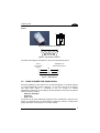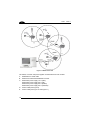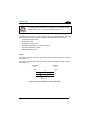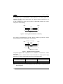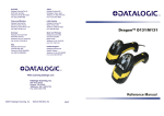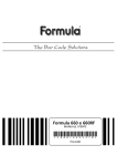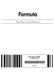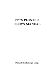
1
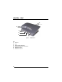
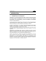
www.mobile.datalogic.com
World wide Sales Network
available from: www.mobile.datalogic.com/contacts
Datalogic Mobile S.r.l.
Via S. Vitalino, 13
40012 Lippo di Calderara di Reno
Bologna - Italy
Telephone: (+39) 051-3147011
Fax: (+39) 051-3147561
Installation Manual
©2001-2007 Datalogic Mobile S.r.l.
822000381 (Rev. B)
08/07
Datalogic Mobile S.r.l.
Via S. Vitalino 13
40012 - Lippo di Calderara di Reno
Bologna - Italy
STARGATE™
Ed.: 08/2007
ALL RIGHTS RESERVED
Datalogic reserves the right to make modifications and improvements without prior notification.
Datalogic shall not be liable for technical or editorial errors or omissions contained herein, nor for incidental or
consequential damages resulting from the use of this material.
Product names mentioned herein are for identification purposes only and may be trademarks and or
registered trademarks of their respective companies.
© Datalogic S.p.A. 2001 - 2007
CONTENTS
COMPLIANCE............................................................................................. iv
Radio Compliance.........................................................................................iv
FCC Compliance........................................................................................... v
Power Supply................................................................................................ v
WEEE Compliance .......................................................................................vi
GENERAL VIEW ....................................................................................... viii
1
1.1
1.2
1.3
1.4
1.5
INTRODUCTION .......................................................................................... 1
Description of STARGATE™ ........................................................................ 1
Package Contents......................................................................................... 3
Status Indicator LED ..................................................................................... 3
Reset Button ................................................................................................. 4
Data Backup ................................................................................................. 4
2
2.1
2.1.1
2.1.2
INSTALLATION............................................................................................ 5
Positioning STARGATE™............................................................................. 5
Desktop Use ................................................................................................. 5
Wall Mounting ............................................................................................... 6
3
3.1
3.2
3.3
CONNECTIONS ........................................................................................... 8
RS232 Connection........................................................................................ 8
RS485 Connection Using F904/N ................................................................. 9
RS485 Connection Using STAR-box™....................................................... 14
4
4.1
4.2
4.3
4.4
4.5
CONFIGURING AND TESTING STAR-SYSTEM™ ................................... 16
STAR-System™ Overview.......................................................................... 16
Loading a SW Application onto an RF Terminal ......................................... 20
RS232 Layout ............................................................................................. 22
RS485 Layout ............................................................................................. 23
Notes for the Programmer........................................................................... 26
5
TROUBLESHOOTING ............................................................................... 28
6
TECHNICAL FEATURES ........................................................................... 29
iii
COMPLIANCE
This device must be opened by qualified personnel only.
RADIO COMPLIANCE
Information for the User
ENGLISH
Contact the competent authority responsible for the management of radio frequency
devices of your country to verify the eventual necessity of a user license. Refer to the
web site http://europa.eu.int/comm/enterprise/rtte/spectr.htm for further information.
ITALIANO
Prendi contatto con l'autorità competente per la gestione degli apparati a radio
frequenza del tuo paese, per verificarne l'eventuale necessità della licenza d'uso.
Inoltre puoi trovare ulteriori informazioni al sito:
http://europa.eu.int/comm/enterprise/rtte/spectr.htm.
FRANÇAIS
Contactez l'autorité compétente en la gestion des appareils à radio fréquence de
votre pays pour vérifier la nécessité du permis d'usage. Pour tout renseignement
vous pouvez vous adresser au site web:
http://europa.eu.int/comm/enterprise/rtte/spectr.htm.
DEUTSCH
Um die Notwendigkeit der Verwendungslizenz zu prüfen, wenden Sie sich an die
Behörde, die auf der Radiofrequenzgerätsführung Ihres Lands bewandert ist. Weitere
Informationen sind verfügbar auf dem Web Site:
http://europa.eu.int/comm/enterprise/rtte/spectr.htm.
ESPAÑOL
Contacta con la autoridad competente para la gestión de los dispositivos de radio
frecuencia de tu país, para verificar si es necesario la licencia de uso. Además se
puede encontrar mas información en el sitio web:
http://europa.eu.int/comm/enterprise/rtte/spectr.htm.
iv
FCC COMPLIANCE
Modifications or changes to this equipment without expressed written approval of
Datalogic could void the authority to use the equipment.
This device complies with PART 15 of the FCC Rules. Operation is subject to the
following two conditions: (1) This device may not cause harmful interference, and (2)
this device must accept any interference received, including interference which may
cause undesired operation.
This equipment has been tested and found to comply with the limits for a Class B
digital device, pursuant to part 15 of the FCC Rules. These limits are designed to
provide reasonable protection against harmful interference in a residential
installation. This equipment generates, uses and can radiate radio frequency energy
and, if not installed and used in accordance with the instructions, may cause harmful
interference to radio communications. However, there is no guarantee that
interference will not occur in a particular installation. If this equipment does cause
harmful interference to radio or television reception, which can be determined by
turning the equipment off and on, the user is encouraged to try to correct the
interference by one or more of the following measures:
Reorient or relocate the receiving antenna.
Increase the separation between the equipment and receiver.
Connect the equipment into an outlet on a circuit different from that to which the
receiver is connected.
Consult the dealer or an experienced radio/TV technician for help.
POWER SUPPLY
DC supply voltage in the range 9 to 30 V DC, intended to be powered by a Class 2
power unit with a cable length <3 m.
CLASS III Equipment:
This equipment is intended for use with UL or CSA Certified, detachable, Class 2
Power Supply (SELV provided by Limited Power Source incorporating isolating
transformer), rated output:
9-20 V dc, 0.1-5 A
or
20-30 V dc, 0.1-3.3 A
!
N2468
v
WEEE COMPLIANCE
Informazione degli utenti ai sensi della Direttiva Europea 2002/96/EC
L’apparecchiatura che riporta il simbolo del bidone barrato deve essere smaltita, alla fine della
sua vita utile, separatamente dai rifiuti urbani.
Smaltire l’apparecchiatura in conformità alla presente Direttiva consente di:
evitare possibili conseguenze negative per l’ambiente e per la salute umana che
potrebbero invece essere causati dall’errato smaltimento dello stesso;
recuperare materiali di cui è composto al fine di ottenere un importante risparmio di
energia e di risorse.
Per maggiori dettagli sulle modalità di smaltimento, contattare il Fornitore dal quale è stata
acquistata
l’apparecchiatura
o
consultare
la
sezione
dedicata
sul
sito
www.mobile.datalogic.com.
Information for the user in accordance with the European Commission Directive
2002/96/EC
At the end of its useful life, the product marked with the crossed out wheeled wastebin must be
disposed of separately from urban waste.
Disposing of the product according to this Directive:
avoids potentially negative consequences to the environment and human health
which otherwise could be caused by incorrect disposal
enables the recovery of materials to obtain a significant savings of energy and
resources.
For more detailed information about disposal, contact the supplier that provided you with the
product in question or consult the dedicated section at the website www.mobile.datalogic.com.
Information aux utilisateurs concernant la Directive Européenne 2002/96/EC
Au terme de sa vie utile, le produit qui porte le symbole d'un caisson à ordures barré ne doit pas
être éliminé avec les déchets urbains.
Éliminer ce produit selon cette Directive permet de:
vi
éviter les retombées négatives pour l'environnement et la santé dérivant d'une
élimination incorrecte
récupérer les matériaux dans le but d'une économie importante en termes d'énergie
et de ressources
Pour obtenir des informations complémentaires concernant l'élimination, veuillez contacter le
fournisseur auprès duquel vous avez acheté le produit ou consulter la section consacrée au site
Web www.mobile.datalogic.com.
Información para el usuario de accuerdo con la Directiva Europea 2002/96/CE
Al final de su vida útil, el producto marcado con un simbolo de contenedor de bassura móvil
tachado no debe eliminarse junto a los desechos urbanos.
Eliminar este producto de accuerdo con la Directiva permite de:
evitar posibles consecuencias negativas para el medio ambiente y la salud derivadas
de una eliminación inadecuada
recuperar los materiales obteniendo así un ahorro importante de energía y recursos
Para obtener una información más detallada sobre la eliminación, por favor, póngase en
contacto con el proveedor donde lo compró o consultar la sección dedicada en el Web site
www.mobile.datalogic.com.
Benutzerinformation bezüglich Richtlinie 2002/96/EC der europäischen Kommission
Am Ende des Gerätelebenszyklus darf das Produkt nicht über den städtischen Hausmüll
entsorgt werden. Eine entsprechende Mülltrennung ist erforderlich.
Beseitigung des Produkts entsprechend der Richtlinie:
verhindert negative Auswirkungen für die Umwelt und die Gesundheit der Menschen
ermöglicht die Wiederverwendung der Materialien und spart somit Energie und
Resourcen
Weitere Informationen zu dieser Richtlinie erhalten sie von ihrem Lieferanten über den sie das
Produkt
erworben
haben,
oder
besuchen
sie
unsere
Hompage
unter
www.mobile.datalogic.com.
vii
GENERAL VIEW
A
B
C
D
E
F
Figure 1 - STARGATE™
Key:
A) Antenna
B) LED
C) Power supply connector
D) Reset/downloading mode button
E) RS232 connector
F) RS485 connectors
viii
INTRODUCTION
1
1 INTRODUCTION
1.1
DESCRIPTION OF STARGATE™
STARGATE™ is a radio base station that enables a wireless network allowing data
transmission between several Datalogic RF devices and an host system (standard
PC, Windows based): STARGATE™ is the core component of the Datalogic
STAR-System™, the system providing a modern and flexible RF Narrow Band
Solution for Mobile applications.
A single STARGATE™ RF base station covers an area of about 8.000 m2 (3000 m2
when working with USA models) outdoors, manages up to 2.000 different mobile
devices and supports up to 255 simultaneous active clients in real time.
To extend the covered area, or to overcome physical limits given by concrete walls,
firewalls or metal shelving, it is possible to exploit the seamless active roaming
capability of the STARGATE™ RF base station network.
This unique feature allows the operators to move in total freedom from office to office
or through different departments/buildings always being connected to the host
application.
STAR-System™ automatically links all the RF devices and their own host
applications, providing a real time fast, reliable and cost-effective wireless connection
between the operators and the most common Windows based software tools, the
most familiar databases or the most widespread ERP/WMS systems.
Thanks to the STAR-Link™ software tool (provided with STARGATE™), it is very
easy to integrate data coming from the Datalogic STAR-System™ into an Excel
spreadsheet or an Access database: even easier for a programmer is the
development of a custom software to exchange data in real time with Formula RF
terminals or Datalogic Hand-Held Readers using Rapid Application Development
languages such as Visual Basic, C++Builder, Delphi etc.
1
STAR H GATE™
1
Features
•
•
•
•
Seamless Active Roaming
Up to 2.000 RF devices supported
Gryphon™ Mobile series
Dragon™ Mobile series
Formula 734 RF Pocket Terminals(*)
Formula 725 RF Hand-Held Terminals(*)
Formula 660 RF Pen Terminals(*)
Up to 16 STARGATE™ RF base station
network
STAR-Link™ software for Windows
Benefits
•
Wide area coverage
•
•
•
•
Real time connection with your
application
Wide
range
of
different
devices able to solve different
applications
in
different
markets
Reliable, Fast & Cost-Effective
system
Full & Easy Windows based
application integration
( )
* not compatible with STARGATE™ USA model
STARGATE™ does not carry out continuous polling, but it is enabled each time an
RF device sends it a sequence of data. This means the radio channel is always free
when RF devices are not transmitting.
The media access protocol used to manage the shared RF channel is called Carrier
Sense Multiple Access Collision Avoidance (CSMA/CA). Once the RF devices have
tried to send data to STARGATE™ simultaneously, the system enables a
transmission delay allowing both of them to communicate with the base station.
The Datalogic CSMA/CA protocol manages the data transmission between
STARGATE™ and the radio device using a 16-bit CRC checksum. Once the
sequences are received by STARGATE™, the base station stores them in its internal
memory until they are requested by the PC.
The communication between STARGATE™ and the PC takes place through a
proprietary binary protocol avoiding collisions on an RS485 line and providing a
16-bit CRC checksum to guarantee information integrity.
The application program running on each RF device must implement the CSMA/CA
protocol, while the PC must run a Data collection software program based on the
STAR-Link™ software tool.
2
INTRODUCTION
1.2
1
PACKAGE CONTENTS
The STARGATE™ Radio Base Station package contains:
−
n. 1 STARGATE™ Radio Base Station;
−
n. 1 STARGATE™ installation manual;
−
n. 1 STAR-Link™ installation CD-ROM;
−
n. 1 antenna (only for European models);
−
n. 1 wall mounting base with 2 threaded dowels and 2 screws;
−
n. 1 fixing plate with 4 screws;
−
n. 4 rubber feet.
CAUTION
1.3
Remove all components from their package. Make sure they are
intact and that they tally with the delivery documents.
Keep the package just in case you need to ship the equipment for
service. Any damage due to inappropriate packaging is not covered
by the warranty.
STATUS INDICATOR LED
STARGATE™ is equipped with a LED indicating its status:
LED
Green
Red
Yellow
Behaviour
Normal Functioning
Firmware Downloading
It is on when the device works It is on if the downloading
correctly.
procedure has occurred correctly.
It blinks each time a data packet
is sent to the PC.
It may blink during the device It is on when an error has
power on or while the device is occurred during the software
working.
downloading.
In the first case, it signals that a
configuration error has occurred.
In the second one, it signals a
connection problem with the PC.
It blinks while starting the
downloading procedure.
3
STAR H GATE™
1
1.4
RESET BUTTON
This button deletes all RAM data restoring the last saved configuration.
By pressing it for 2.5 seconds the yellow light starts blinking and it goes on by
releasing the button. This light signals that STARGATE™ has entered the firmware
downloading mode. While working in this mode the base station current configuration
is
deleted
and
substituted
with
the
default
one
(Base
station
address = 2000; interface = RS232). Then, it is possible to download the firmware
update through the dedicated software running on the PC. If the downloading occurs
successfully, the program will be launched directly by the system.
By pressing the Reset button for 2.5 seconds the base station
current configuration will be deleted.
CAUTION
1.5
DATA BACKUP
A backup of the data saved to STARGATE™ RAM memory is available in case of
power going down. STARGATE™ maintains the data for a maximum of 3 hours.
Then, data is definitely lost.
This feature is only available from the software release 1.10 referring to the software
running on the base station and displayed when enabling the Alive button in RS232
connection (see step 8 in par. 4.3).
4
INSTALLATION
2
2 INSTALLATION
2.1
POSITIONING STARGATE™
Before connecting the STARGATE™ base station, it is first necessary to position it
so that the RF transmission and reception is possible.
To position STARGATE™, bear in mind the following fundamental guidelines:
1.
the maximum distance between base station and RF device is about 50 m (30 m
for STARGATE™ USA model) in surfaces which are perpendicular to the base
station antenna;
2.
the effective radio coverage depends on the physical structure of the
environment in which it operates, and to the presence or absence of obstacles
(metal structures, walls, electrical systems, etc.);
3.
the base station operates at temperatures between -20° (-4°) and + 50 °C (+122
°F), with humidity at less than 90% (no condensation);
4.
to obtain the best reception/transmission performance, mount the
STARGATE™ base station away from large metal structures which could absorb
or reflect Radio Frequency;
STARGATE™ can be mounted for desktop usage or it can be fixed to a wall.
2.1.1
Desktop Use
For desktop use, STARGATE™ is already correctly positioned :
1.
2.
3.
Carefully clean the rubber feet seat of the STARGATE™ base to remove any
impurities that could reduce adhesion;
Remove the protective plastic from the rubber feet and stick them onto the
bottom surface of the base;
Insert the antenna in the appropriate hole on the body of the base station and
screw it clockwise until tight.
If working with a STARGATE™ USA model, skip step 3, since the
antenna is fixed and not removable.
CAUTION
5
STAR H GATE™
2
2.1.2
Wall Mounting
Before performing the following operation, mount the fixing plate on the
STARGATE™ bottom surface by means of the four screws. Then, slide the wall
mounting base along the fixing plate and fix it through the set - screw. Do not screw it
too tight in order to allow the wall mounting base to slide out.
Screws
Fixing plate
Figure 2 - Fixing Plate on STARGATE™ Base
6
INSTALLATION
2
For wall mounting, fix the related plate as follows:
Mounting holes
Fixing plate guide
Set - screw
Figure 3 - Wall Mounting Base
1.
2.
3.
4.
5.
6.
Using the mounting holes on the plate as a pattern mark the wall where you
desire to mount STARGATE™;
Drill two appropriate size holes;
Insert the threaded dowels into the holes;
Position the plate on the wall and affix it by means of the two screws;
Insert STARGATE™ (as shown in Figure 3) by sliding the fixing plate along the
guide on the mounting base;
Fix it by means of the set - screw if necessary.
7
STAR H GATE™
3
3 CONNECTIONS
STARGATE™ can be connected to the PC through an RS232 or an RS485 line. It is
possible to set the base station by sending the configuration of the desired
connection through the software running on the PC (see par. 4.3 and par. 4.4).
3.1
RS232 CONNECTION
If the required coverage area is supplied by a single STARGATE™ and the distance
between the PC and STARGATE™ is < 15 m, it is possible to connect it to a PC
through an RS232 interface (default connection). The hardware system is composed
by a PC, one STARGATE™, a serial cable, a power supply connected to the base
station and a given number of RF devices.
Figure 4 - RS232 Connection
The following cables and power supplies are listed with their order number:
A.
94A054270 6 m serial cable
90ACC1070 9-pin adapter
B.
94ACC4050 power supply 110 V (USA)
94ACC4060 power supply 240 V (UK)
94ACC4070 power supply 220 V (EURO)
94ACC4500 power supply 240 V (Australia)
8
CONNECTIONS
3
Pinout
8
1
Figure 5 - RJ45 Modular Connector
5
4
9
3
8
2
7
1
6
Figure 6 - 9-pin Female Connector
The cable connecting the base station to the PC has the following pinout:
PC side
STARGATE™ side
9-pin connector
(female)
RJ45 modular connector
RX
2
3
TX
GND
5
2
1
5
Figure 7 - RS232 Pinout
3.2
RS485 CONNECTION USING F904/N
Several STARGATE™ base stations can be chained together in an RS485 network
or a single STARGATE™ having a distance > 15 m from the PC can be connected.
The (first) base station is connected to the PC through an F904/N
RS232/485 converter set to the following default parameter values (see the F904/N
relevant manual for details):
− baud rate: 38400 bps
− data bits: 8
− parity: none
The power can be either individually supplied to each STARGATE™ present in the
system or propagated from one base station to another by means of a single power
supply (see Figure 10 and Figure 11 for further details).
9
STAR H GATE™
3
Figure 8 - RS485 Connection
The cables, converter and power supplies are listed with their order number:
A. 94A054000 2 m serial cable
B. 94ACC4470 F904/N RS232/RS485 converter
C. 94ACC4050 power supply 110 V (USA)
94ACC4060 power supply 240 V (UK)
94ACC4070 power supply 220 V (EURO)
94ACC4500 power supply 240 V (Australia)
D. Custom cable (see Figure 9)
E. Custom cable (see Figure 10 and Figure 11)
10
CONNECTIONS
3
To configure the STARGATE™ base station use the cable and the
adapter listed in par. 3.1. For further details see par. 4.3.
CAUTION
The RS485 bus system and the eventual power are propagated from one base
station to another through a cable having the following minimum characteristics:
−
2 twisted pair AWG 24 wire
−
Impedance: 120 Ω
−
Propagation velocity: 66%
−
Capacitance between two connectors: 49 pF/m
−
Conductor resistance: 0.8 Ω/m
−
Maximum length: 1200 m
Pinout
The custom cables to be used in the RS485 connection have two RJ45 connectors
(see Figure 5).
The cable connecting the first base station to the RS232/RS485 converter has the
following pinout:
STARGATE™
side
CONVERTER
side
RJ45
3
6
RJ45
VDCRS485RS485+
7
5
2
1
Twisted Pair
Figure 9 - Converter/STARGATE™ Custom Cable Pinout
11
STAR H GATE™
3
If connecting up to 16 STARGATE™ base stations in the same system, it is
necessary to use a custom cable having two different pinouts depending on the
network configuration.
If each STARGATE™ present in the system is individually powered, the custom
cable pinout is the following:
RJ45
RJ45
VDC5
2
1
5
RS485-
2
RS485+
1
Twisted pair - RS-485 bus
Figure 10 - Powering Each STARGATE™ Individually
If the power is propagated from one base station to another by means of a single
power supply, the custom cable pinout is the following:
Twisted pair - Power supply
RJ45
8
VDC+
RJ45
8
VDC-
5
2
1
5
RS485-
2
RS485+
1
Twisted pair - RS-485 bus
Figure 11 - System with Power Propagation
The power supply should be positioned in the middle of the network for a better
functioning.
The total number of devices which can be connected to a single power supply
depends on the power supply voltage as shown in the following table:
Supply Voltage
Consumption
Max. Number of Devices
12 V
24 V
30 V
232 mA
344 mA
390 mA
4
8
10
Note: The values refer to a system adopting a cable 50 m long to connect the base
stations together.
12
CONNECTIONS
3
If using a shielded cable, it is necessary to link the cable shields together (see
Figure 12) and connect them to the earth ground in only one point.
We suggest to use your PC ground (when provided) to make the connection to the
earth ground.
Figure 12 - Linking the Cable Shields
Network Termination
Before proceeding with this operation ensure that the base station
is not powered.
WARNING
The RS485 bus must be properly terminated by positioning a jumper in the
RS232/485 converter (see the relevant manual) and in the last STARGATE™ on the
network. To position the jumper proceed as follows:
If working with a STARGATE™ USA model, skip step 1 and step 6,
since the antenna is fixed and not removable.
CAUTION
1.
2.
3.
4.
5.
6.
remove the STARGATE™ antenna by
unscrewing it (counter-clockwise);
unscrew the four cover screws on the base;
detach the base from the upper part of the
station;
position the jumper as shown in Figure 13;
close the base screwing the four cover
screws;
install the antenna screwing it clockwise until
tight.
Jumper
Figure 13 - Jumper Positioning
13
STAR H GATE™
3
3.3
RS485 CONNECTION USING STAR-BOX™
Several STARGATE™ base stations can be chained together in an RS485 network
or a single STARGATE™ having a distance > 15 m from the PC can be connected.
The (first) base station is connected to the PC through an active STAR-Box™
RS232/485 converter set to the following default parameter values (see the
STAR-Box™ relevant manual for details):
−
baud rate: 38400 bps
−
data bits: 8
−
parity: none
Figure 14 - RS485 Connection
The cables and STAR-Box™ are listed with their order number:
A. 94A054000 2 m serial cable (refer to STAR-Box™ manual for jumper settings)
94A054270 6 m serial cable (refer to STAR-Box™ manual for jumper settings)
B. 94ACC1190 Active STAR-Box™ Converter
C. Custom cable, i.e. Belden 9842 (see STAR-Box™ relevant manual for details)
D. 94ACC4682 Passive STAR-Box™
E. 94A054020 RS485 serial cable
14
CONNECTIONS
3
Network Termination
The RS485 bus must be properly terminated by positioning a jumper in both the last
STAR-Box™ device and the first STAR-Box™ device on the network bus and NOT
inside STARGATE™.
Refer to the STAR-Box™ relevant manual to get further information about
connections, system wiring and bus termination.
15
STAR H GATE™
4
4 CONFIGURING AND TESTING STAR-System™
4.1
STAR-System™ OVERVIEW
Two different layouts are provided depending on the application needs. Each layout
may consist of a single STARGATE™ or a network of several RF base stations.
An RF device is logically linked to only one STARGATE™ RF base station at a time.
In case of a network layout it can choose dynamically the best base station to be
linked to allowing the handover from one cell to another. The routing of data packets
from the application running on the RF device to the application running on the host
PC is managed by the protocol: the designer of the application does not need to
control the STARGATE™ base stations since data transactions are peer to peer
between RF devices and the host PC.
Each STARGATE™ RF base station and each RF device is identified by a unique
address: two RF devices or two base stations cannot have the same address (while
an RF device can have the same address as a base station).
It is necessary to assign the address to the base stations, then, when starting up the
RF protocol on an RF device, you must specify three other addresses:
1.
RF device address
2.
address of the first base station with which to communicate
3.
address of the last base station with which to communicate
The address range for RF devices is from 0 to 1999 while the address setup mode
depends on the device type (see the relevant manual).
The address range for STARGATE™ RF base stations is also from 0 to 1999. In
addition, there is a factory default address whose value is 2000. This means that the
base station needs to be correctly configured before starting to use it. The
STARGATE™ configuration can be also defined by sending commands to the base
station through the PC serial interface specifying the broadcast address: 2047. This
address is very useful to get the configuration from a base station having an
unknown address.
CAUTION
When requesting a base station configuration by using the
broadcast address, only one STARGATE™ must be connected
within the network.
The first and last base station addresses specified on the RF device must have the
same value whenever a layout is composed of a single STARGATE™.
16
CONFIGURING AND TESTING STAR-System™
4
If the system has been started correctly (invoking the proper STAR-Link™ ActiveX
method) and the network initialization has been completed, the registration of the RF
device in the network and the first data transaction occur at the same time.
Then, the RF device will send information to the host PC identifying the RF device
type and the RF library version. Finally, it will transmit the data packet taken from the
application program.
On the other hand, if the communication with the first base station in a network layout
fails, the RF device will try to communicate with other base stations having an
address in the range specified in steps 2 – 3 and following an increasing order. This
procedure requires the base stations involved in the roaming of an RF device to have
adjacent addresses.
Using a wrong base address range in the RF device configuration could lead to a
useless increase of the latency time.
As explained before, for each RF device you can specify the set of bases it can
communicate with. This can be used to define subsets of the base stations: you may
have RF devices working with all the bases and RF devices working with only one or
two of them (e.g. specifying for points 2 and 3 the range 1000 -1000 or 1001 - 1002),
while the base stations communicate with every RF device asking for it (according to
the memory limits).
Once the first transaction is completed, the RF device is registered in the network
and automatically and dynamically establish the communication with the best base
station within the address range specified.
17
STAR H GATE™
4
NOTE
Be careful when installing two separate networks having overlapping
RF coverage areas. In this case no RF device nor STARGATE™ RF
base station must share the same address considering the total
number of RF devices (see Figure 15).
Figure 15 - Separate STAR-System(s)™ with Overlapping Coverage Areas
The same care must be taken if a STARGATE™ RF base station(s) and the RF
devices are placed near one or more point-to-point cordless systems. Neither the RF
devices nor the point-to-point and STARGATE™ RF base stations must share the
same address:
Figure 16 - STAR-System™ and Other RF Networks Having Overlapping Coverage Areas
18
CONFIGURING AND TESTING STAR-System™
4
Example
If working with an installation composed of 4 point-to-point cordless systems (RF
device with its base), 4 STARGATE™ RF base stations connected to 1 host PC via
RS485 and 10 RF devices exchanging data with that host, a correct set of addresses
could be:
point-to-point:
base stations
10
11
12
13
RF devices
10
11
12
13
network:
STARGATE™ RF base stations (cannot be in range 10 – 13)
100
101
102
103
RF devices (cannot be in range 10 – 13)
50
51
52
53
54
55
56
57
58
59
19
STAR H GATE™
4
4.2
LOADING A SW APPLICATION ONTO AN RF TERMINAL
The following procedure is not valid for STARGATE™ USA model.
This example explains how to load the demo software (provided by the STAR-Link™
CD-ROM) onto an RF terminal:
1.
Connect the terminal cradle to the PC COM1 by means of the serial cable and
insert the RF terminal into its cradle;
2.
Set the RF terminal to bootloader state (if it is already in this state jump to
step IV);
3.
Insert a blunt-ended object into the hole positioned under the display in order to
cause the question "PROGRAM ERASE?" to be displayed; answer "yes" by
pressing the down arrow;
4.
The following message is displayed:
BOOTSTRAP-LOADER vxxx WaitDownload;
5.
Run the STAR-Link_FXXXExample.bat command positioned in the STAR-Link
installation directory (ex.: C\ProgramFiles\Datalogic\STAR-Link\Examples Demo)
by choosing one of the following procedures:
a) Click on the Windows Start button and choose the Run option; then, write
the complete path of the .bat file in the appearing Edit box;
b) Open from Windows Explorer the installation directory, select the .bat file
and press the ENTER key from the keyboard. The following DOS window
will be displayed and the FXXXDEMO.HEX demo file is automatically
loaded onto the RF terminal:
Figure 17 - SW Downloading Window
A progressive white line appears below the line showing the download
percentage and displays the time required to complete the procedure;
20
CONFIGURING AND TESTING STAR-System™
6.
4
If the downloading procedure has completed successfully (after a series of
messages about automatic tests have been displayed and several beeps have
been emitted), the following message appears:
DATALOGIC RF DEMO
Any Key to start
Or F4 to Set
Press F4 and set the following parameters:
Addr.
F.Sta.
L.Sta.
Act. Dev.:
CAUTION
: ID address for RF terminal in the range 0-1999
: ID address for the first STARGATE™ to send data to in the range
0-1999
: ID address for the last STARGATE™ to send data to in the range
0-1999
: Number of devices simultaneously active in the RF network (range
1-2000)
If the data is sent to one STARGATE™ only, the F.Sta. and L.Sta.
address must correspond to the address of the STARGATE™ that
is being used.
21
STAR H GATE™
4
4.3
RS232 LAYOUT
This procedure is intended to be a step-by-step guide explaining how to configure a
STARGATE™ RF Base Station by using the Visual Basic example provided in the
STAR-Link™ CD-ROM and based upon the STAR-Link ActiveX. The procedure
assumes the STARGATE™ RF Base Station has a factory default address. If
working with the base station previously configured, in step 4 digit the address value
2047 instead of 2000:
1.
Connect STARGATE™ to the PC serial port and power it (see Figure 4);
2.
Run the Visual Basic demo example on the PC: click the Windows Start
button, select Visual Basic example from the path ProgramsÙDatalogicÙSTARLinkÙExamples; then, the STAR-Link VB Example dialog box will be displayed. If
the connection does not use COM1 port (default serial port), select the Control
settings option from the Settings menu. The Properties settings dialog box
appears allowing to select a different port. Then, click OK to confirm the new
value and close the dialog box;
3.
Select the Base stations option from the Settings menu: the RF Base stations
dialog box appears;
4.
Digit 2000 in the Edit box positioned in the right upper part of the dialog box and
click on the Add button. The address will then be displayed in the list on the left;
5.
Select the 2000 address number from the list and click on the Config button. A
window showing the STARGATE configuration parameters will appear;
6.
Double-click on the Address parameter and the Setting value dialog box will be
displayed. Change the address value in the range 0-1999 and click on the OK
button to confirm and exit the dialog box;
DO NOT CHANGE CONFIGURATION PARAMETERS OTHER THAN
ADDRESS.
7.
Send the new configuration to STARGATE™ by clicking on
Update Cfg button. Then, click on the EXIT button to exit the dialog box;
8.
To test the PC/STARGATE communication select the STARGATE™ new
address from the RF Base Stations dialog box. Then, click on the Alive button. If
the connection is right a dialog box showing the DL STARGATE xxx string
appears. In case of wrong connection the message BASE STATION NOT
CONNECTED is displayed;
9.
Close the RF Base Stations dialog box by clicking on the Exit button;
22
the
CONFIGURING AND TESTING STAR-System™
4
10. Set the STARGATE™ (European models only) new address on the RF
terminal (loading a software application as described in par. 4.2) as first and
last base station to which sending the data packets in 1way or 2 way mode (see
par. 4.5). Set the STARGATE™ (both European and USA models) new
address on the Gryphon™ M or Dragon™ M RF device as first and last
STAR-System™ address to which sending the data packets (see relevant
manuals for details). To make Visual Basic answer to a device sending data in 2
way mode it is necessary that the device belongs to the list of the network
devices. (Before starting the polling procedure, register the device address by
selecting the Devices option from the Settings menu and adding the new
address to the list);
11. Save the current network configuration (PC/STARGATE™ communication
parameters, list of base stations and devices belonging to the network) by
selecting the Save configuration option from the Settings menu. When running
the program in Visual Basic again, and selecting the option Load configuration
from the Settings menu, you do not need to configure the network to start the
data polling;
12. Select the Open option from the Network menu to start polling STARGATE™.
Now, the program is ready to display the data packets sent to the base stations
in the application window.
4.4
RS485 LAYOUT
This procedure is intended to be a step-by-step guide explaining how to configure an
RS485 network composed of N number of STARGATE™ RF Base Stations. This
procedure assumes the STARGATE™ RF Base Stations have a factory default
address. If working with base stations previously configured, in step 5 digit the
address value 2047 instead of 2000. Before connecting the base stations to the
RS485 network, it is necessary to set the right address and the RS485 interface for
each base station. We also suggest to apply a label on each STARGATE™
indicating the corresponding address:
1. Define a set of consecutive addresses to be assigned to the N number of
base stations (the range is from 0-1999); for example, from M to (M+N-1). Refer
to par. 4.1 for details;
2. Connect the first STARGATE™ to the PC serial port and power it (see
Figure 4);
3. Run the Visual Basic demo example on the PC: click the Windows Start
button, select Visual Basic example from the path ProgramsÙDatalogicÙSTARLinkÙExamples; then, the STAR-Link VB Example dialog box will be displayed. If
the connection does not use COM1 port (default serial port), select the Control
settings option from the Settings menu. The Properties settings dialog box
appears allowing to select a different port. Then, click OK to confirm the new
value and close the dialog box;
23
4
4.
5.
6.
7.
8.
9.
10.
11.
12.
13.
14.
15.
16.
17.
18.
24
STAR H GATE™
Select the Base stations option from the Settings menu: the RF Base stations
dialog box appears;
Digit 2000 in the Edit box positioned in the right upper part of the dialog box and
click on the Add button. The address will then be displayed in the list on the left;
Select the 2000 address number from the list and click on the Config button. A
window showing the STARGATE configuration parameters will appear;
Double-click on the Address parameter and the Setting value dialog box will be
displayed. Change the address value in the range 0-1999 and click on the OK
button to confirm and exit the dialog box;
In the dialog box listing the configuration parameters select the RS485 interface
value by double-clicking on the Interface parameter. Then, click on the OK
button to confirm and exit the dialog box;
DO NOT CHANGE CONFIGURATION PARAMETERS OTHER THAN
ADDRESS AND INTERFACE.
Send the new configuration to STARGATE™ by clicking on the
Update Cfg button. Then, click on the EXIT button to exit the dialog box;
Disconnect the first STARGATE™ and connect individually the other ones
to the PC serial port and power them;
For each STARGATE™ digit 2000 in the Edit box positioned in the right upper
part of the dialog box and click on the Add button. The address will then be
displayed in the list on the left;
For each STARGATE™ select the 2000 address number from the list and click
on the Config button. A window showing the STARGATE™ configuration
parameters will appear;
Double-click on the Address parameter and the Setting value dialog box will be
displayed. Change the address value in the range 0-1999 and click on the OK
button to confirm and exit the dialog box;
In the dialog box listing the configuration parameters select the RS485 interface
value by double-clicking on the Interface parameter. Then, click on the OK
button to confirm and exit the dialog box;
DO NOT CHANGE CONFIGURATION PARAMETERS OTHER THAN
ADDRESS AND INTERFACE.
Send the new configuration to the STARGATE™ individually connected by
clicking on the Update Cfg button. Then, click on the EXIT button to exit the
dialog box;
Once all the base stations have been configured, close the RF Base Stations
dialog box by clicking on the Exit button;
Set the communication parameters of the RS232/RS485 converter and
position the jumpers terminating the network (see par. 3.2 and par. 3.3);
Physically connect the STARGATE™ base stations in the RS485 network;
CONFIGURING AND TESTING STAR-System™
4
19. If the RS485 network is connected through a serial port different from the one
previously used to configure the base stations, select the Control settings option
from the Settings menu. The Properties settings dialog box appears allowing to
select a different port. Then, click OK to confirm the new value and close the
dialog box;
20. Set the first and the last base station addresses (for European models
only) on the RF terminal (loading a software application as described in par.
4.2) from which the data packets will be sent in 1 way or 2 way mode (see par.
4.5). Set the first and last STAR-System™ addresses (both European and
USA models) on the Gryphon™ M or Dragon™ M RF device from which the
data packets will be sent (see relevant manuals for details). These addresses
must follow the order M and (M+N-1), or a subset. To make Visual Basic answer
to a device sending data in 2 way mode it is necessary that the device belongs
to the list of the network devices. (Before starting the polling procedure, register
the device address by selecting the Devices option from the Settings menu and
adding the new address to the list);
21. Save the current network configuration (PC/STARGATE™ communication
parameters, list of base stations and devices belonging to the network) by
selecting the Save configuration option from the Settings menu. When running
the program in Visual Basic again, and selecting the option Load configuration
from the Settings menu, you do not need to configure the network to start the
data polling;
22. Select the Open option from the Network menu to start polling the
STARGATE™ base stations listed in the RF Base Stations dialog box. Now, the
program is ready to display the data packets sent to the base stations in the
application window.
25
STAR H GATE™
4
4.5
NOTES FOR THE PROGRAMMER
STARGATE™ does not carry out continuous polling, but it is only enabled each time
an RF device sends it a sequence of data. This means the radio channel is always
free when the RF devices are not transmitting.
The media access procedure used to manage the shared RF channel is a Carrier
Sense Multiple Access Collision Avoidance (CSMA/CA) protocol that aims to
minimize the number of collisions of packets sent by different RF devices.
In terms of global throughput of the entire system a single RF device is not able to
exploit the whole capability of the cell (bytes of data per second). By adding RF
devices there is an increase of the global throughput and then a saturation (the total
throughput remains constant and the throughput of the single RF device is the total
number divided by the number of RF devices).
Therefore, the useful number of RF devices per cell depends on the traffic generated
by the specific application (the higher the number of packets per second for an RF
device, the lower the number of RF devices for a given latency time).
The system functioning is based upon a client-server architecture, where each
operation is driven by the RF device (client). In this way the data cannot be sent to
the device from the PC application. This is only possible when it is the RF device
asking for it.
The protocol allows transferring data packets up to 240 bytes. Data transfer is always
requested by the RF device and it may occur according to the following modes:
•
1 way mode: the RF device requests to send a data packet to the host and waits
for an acknowledgement from the STARGATE™ RF base station only;
•
2 way mode: the RF device requests to send a data packet to the host and waits
for a data packet in response (this is the only way to receive data from the host
PC). If this transaction ends successfully, the application program can retrieve
the response packet from the protocol library.
For best performance do not exceed 240 bytes for each transaction.
If working in 2 way mode, this value corresponds to the sum of the
sent data and the received data.
NOTE
26
CONFIGURING AND TESTING STAR-System™
4
Both the transactions (1 way and 2 way) must have an acknowledgement back to be
completed correctly. This assures that the application program always knows if the
data packet has been correctly delivered or not.
In case the RF device does not receive the acknowledgement packet, the transaction
fails due to timeout. Then, the device is not able to know if the data packet has
correctly arrived to the network or not.
To correctly manage this situation, you must not start a further request of an old data
packet if the previous one failed. This attempt could lead to a duplication of the data
on the application running on the host PC.
Rather the protocol gives a function to the application designer on the RF device that
must be used to retry a failed transaction instead of the normal data transaction
request.
The STAR-Link ActiveX running on the host PC signals the arrival of a data packet
from an RF device through an event and provides a method to send back a data
packet if the request is in two way mode (see relevant manual).
27
STAR H GATE™
5
5 TROUBLESHOOTING
PROBLEMS
CAUSES
REMEDY
STARGATE™ is not
powered.
Supply STARGATE™.
The connecting cable is
broken or it is not correctly
connected.
Check the cable is in
good condition and
connected correctly.
During configuration a
wrong communication
interface has been
selected.
Set the communication
interface correctly.
The STARGATE™ base
A wrong address has been
station cannot
communicate with the PC. configured.
The RS232/485 converter
is not powered in the
RS485 network.
Set the address correctly.
Supply the RS232/485
converter.
Set the communication
The RS232/485 converter
parameters correctly
communication parameters
(refer to the converter
are incorrect.
manual).
The RF communication
between an RF device
and STARGATE™ is not
possible.
28
The RS485 network has
not been terminated.
Insert the network
terminator.
A wrong address has been
configured.
Set the address correctly.
The software running on
the PC does not work.
Start the software running
on the PC.
The device is out of the
coverage area.
Position the RF device
closer to STARGATE™.
TECHNICAL FEATURES
6
6 TECHNICAL FEATURES
Electrical Features
Micro-controller
Program memory
Data memory
Supply voltage
Power consumption
Radio Features
Working frequency
Bit rate
Effective radiated power
Range (in open air)
RF Modulation
Environmental Features
Working temperature
Storage temperature
Humidity
Protection class
Mechanical Features
Weight (without fixing plate)
Dimension (without antenna)
LED
16bit CMOS
128 Kb
128 Kb
9..30 Vdc
600 mW
European Models
USA Models
433.92 Mhz
19200 baud
<10 mW
50 m / 164 ft
910 Mhz
36800 baud
<1 mW
30 m / 98.4 ft
FSK
-20° to +50 °C / -4° to 122 °F
-20° to +70 °C / -4° to 158 °F
90% non condensing
IP30
210 g / 7.4 oz
141 x 111 x 52 mm / 5.6 x 4.4 x 2.0 in
Power on/Data (green)
Communication/Downloading error (red)
Firmware downloading (yellow)
29
Datalogic Mobile S.r.l.
Via S. Vitalino 13
40012 - Lippo di Calderara
Bologna - Italy
07
dichiara che
declares that the
déclare que le
bescheinigt, daß das Gerät
declare que el
STARGATE, RF433MHz Base Station
e tutti i suoi modelli
and all its models
et tous ses modèles
und seine modelle
y todos sus modelos
sono conformi alla Direttiva del Consiglio Europeo sottoelencata:
are in conformity with the requirements of the European Council Directive listed below:
sont conformes aux spécifications de la Directive de l'Union Européenne ci-dessous:
der nachstehenden angeführten Direktive des Europäischen Rats entsprechen:
cumple con los requisitos de la Directiva del Consejo Europeo, según la lista siguiente:
1999/5/EEC R&TTE
Questa dichiarazione è basata sulla conformità dei prodotti alle norme seguenti:
This declaration is based upon compliance of the products to the following standards:
Cette déclaration repose sur la conformité des produits aux normes suivantes:
Diese Erklärung basiert darauf, daß das Produkt den folgenden Normen entspricht:
Esta declaración se basa en el cumplimiento de los productos con las siguientes normas:
EN 60950-1, December 2001:
INFORMATION TECHNOLOGY
REQUIREMENTS
ETSI EN 301 489-3 v1.4.1, August 2002:
ELECTROMAGNETIC COMPATIBILITY AND RADIO SPECTRUM MATTERS (ERM);
ELECTROMAGNETIC COMPATIBILITY (EMC) STANDARD FOR RADIO EQUIPMENT AND
SERVICES; PART 3:SPECIFIC CONDITIONS FOR SHORT-RANGE DEVICES (SRD)
OPERATING ON FREQUENCIES BETWEEN 9 KHZ AND 40 GHZ
EQUIPMENT
–
SAFETY-
PART
1
:
GENERAL
ETSI EN 300 220 v1.1.1, September 2004: ELECTROMAGNETIC COMPATIBILITY AND RADIO SPECTRUM MATTERS (ERM); SHORTRANGE DEVICES (SRD); RADIO EQUIPMENT TO BE USED IN THE 25 MHZ TO 1000 MHZ
FREQUENCY RANGE WITH POWER LEVELS RANGING UP TO 500 MW; PART 3:
HARMONIZED EN COVERING ESSENTIAL REQUIREMENTS UNDER ARTICLE 3.2 OF THE
R & TTE DIRECTIVE
Lippo di Calderara, August 22nd, 2007
Paola Chientaroli
Quality Assurance Manager
www.mobile.datalogic.com
World wide Sales Network
available from: www.mobile.datalogic.com/contacts
Datalogic Mobile S.r.l.
Via S. Vitalino, 13
40012 Lippo di Calderara di Reno
Bologna - Italy
Telephone: (+39) 051-3147011
Fax: (+39) 051-3147561
Installation Manual
©2001-2007 Datalogic Mobile S.r.l.
822000381 (Rev. B)
08/07