1
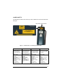
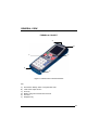
Formula Color™
User’s Manual
FORMULA COLOR™
USER’S MANUAL
DATALOGIC S.p.A.
Via Candini 2
40012 – Lippo di Calderara di Reno
Bologna – Italy
Formula Color™ – User’s Manual
Ed.: 03/2006
ALL RIGHTS RESERVED
Datalogic reserves the right to make modifications and improvements without prior notification.
Datalogic shall not be liable for technical or editorial errors or omissions contained herein, nor for incidental or
consequential damages resulting from the use of this material.
Product names mentioned herein are for identification purposes only and may be trademarks and or
registered trademarks of their respective companies.
© Datalogic S.p.A. 2004 - 2006
822000461 (Rev. B)
CONTENTS
REFERENCES ............................................................................................. v
Conventions .................................................................................................. v
Reference Documentation ............................................................................ v
Services and Support.................................................................................... v
SAFETY REGULATIONS............................................................................ vi
General Safety Rules ....................................................................................vi
Laser Safety.................................................................................................vii
Radio Compliance......................................................................................... x
Information for the User ................................................................................xi
FCC Compliance..........................................................................................xii
WEEE Compliance ......................................................................................xii
GENERAL VIEW ....................................................................................... xiii
QUICK START .......................................................................................... xiv
1
1.1
1.2
1.3
INTRODUCTION .......................................................................................... 1
Formula Color™ Terminal Description.......................................................... 1
Package Contents......................................................................................... 2
Accessories................................................................................................... 3
2
2.1
2.1.1
2.1.2
2.2
2.2.1
2.2.2
2.3
CONNECTIONS ........................................................................................... 4
Cradles ......................................................................................................... 4
F-Color Single Cradle ................................................................................... 4
F-Color Vehicle Cradle.................................................................................. 6
Connection to the Host Computer................................................................. 8
RS232 Connection via Cradle....................................................................... 8
RF Connection .............................................................................................. 9
Connection Cables...................................................................................... 10
3
3.1
3.2
3.3
3.4
3.5
3.6
3.6.1
3.6.2
3.6.3
3.6.4
3.6.5
BIOS SETUP MENU................................................................................... 11
General Information .................................................................................... 11
Activating the Setup Procedure................................................................... 11
Password .................................................................................................... 12
The Setup Menu and Its Configurable Items............................................... 12
Changing the Values of the Menu Items ..................................................... 13
Structure of the Formula Color™ Setup Pages........................................... 13
Console....................................................................................................... 14
Status Bar ................................................................................................... 15
Indications................................................................................................... 16
Devices ....................................................................................................... 17
PMU Config................................................................................................. 18
iii
3.6.6
3.7
Activities...................................................................................................... 19
Exit from the Setup Procedure .................................................................... 20
4
4.1
4.2
4.3
4.4
USE AND FUNCTIONING .......................................................................... 21
Terminal Startup ......................................................................................... 21
Barcode Scanning....................................................................................... 22
Description of the Keys ............................................................................... 23
File Transfer................................................................................................ 26
5
5.1
5.2
5.3
MAINTENANCE ......................................................................................... 27
Charging the Batteries ................................................................................ 27
Replacing the Batteries ............................................................................... 27
Cleaning the Terminal................................................................................. 29
6
TROUBLESHOOTING ............................................................................... 30
7
7.1
7.2
7.3
TECHNICAL FEATURES ........................................................................... 34
Formula Color™ Technical Features .......................................................... 34
F-Color Single Cradle Technical Features .................................................. 36
Reading Diagram ........................................................................................ 37
8
TEST CODES ............................................................................................. 38
GLOSSARY................................................................................................ 41
INDEX ......................................................................................................... 44
iv
REFERENCES
CONVENTIONS
This manual uses the following conventions:
"User" refers to anyone using a Formula Color™ terminal.
"Terminal" refers to the Formula Color™ terminal.
"You" refers to the System Administrator or Technical Support person using this
manual to install, configure, operate, maintain or troubleshoot a Formula Color™
terminal.
REFERENCE DOCUMENTATION
For further information regarding Formula Color™ configuration, please refer to the
following users' manuals:
-
DL DTP User's Manual
-
TDTPClient Reference Manual
-
DS for Formula DOS Development System Manual
SERVICES AND SUPPORT
Datalogic provides several services as well as technical support through its website.
Log on to www.datalogic.com and click on the links indicated for further information
including:
•
PRODUCTS
Search through the links to arrive at your product page where you can download
specific Manuals and Software & Utilities.
•
SERVICES & SUPPORT
- Datalogic Services - Warranty Extensions and Maintenance Agreements
- Authorised Repair Centres
•
CONTACT US
E-mail form and listing of Datalogic Subsidiaries
v
SAFETY REGULATIONS
NOTE
Read this manual carefully before performing any type of connection
to the Formula Color™ terminal.
The user is responsible for any damages caused by incorrect use of
the equipment or by inobservance of the indication supplied in this
manual.
GENERAL SAFETY RULES
Use only the components supplied by the manufacturer for the specific Formula
Color™ terminal being used. The use of cradles other than those supplied with the
Formula Color™ terminal or indicated in the list in par. 1.3 could cause serious
damage to the Formula Color™ terminal.
Do not attempt to disassemble the Formula Color™ terminal, as it does not contain
parts that can be repaired by the user. Any tampering will invalidate the warranty.
When replacing the batteries or at the end of the operative life of the Formula Color™
terminal, disposal must be performed in compliance with the laws in force.
Do not submerge the terminal in liquid products.
vi
LASER SAFETY
The laser light is visible to the human eye and is emitted from the window indicated in
the figure.
Laser beam output window
This product complies with
21 CFR Subchapter J
AVOID EXPOSURE
LASER LIGHT
IS EMITTED FROM
THIS APERTURE
LASER LIGHT - DO NOT STARE INTO BEAM
CLASS 2 LASER PRODUCT
MAX. OUTPUT RADIATION 1.4 mW
EMITTED WAVE LENGTH 630~680 nm
EN60825-1:2001
CAUTION - CLASS 2 LASER LIGHT WHEN OPEN - DO NOT STARE INTO BEAM
Figure 1 – Formula Color™ Laser Safety and Data Label
D
F
E
La luce laser è visibile
all'occhio umano e
viene emessa dalla
finestra indicata nella
figura.
I
Die Laserstrahlung ist für
das menschliche Auge
sichtbar und wird am
Strahlaustrittsfenster
ausgesendet (siehe Bild).
Le rayon laser est visible
à l'oeil nu et il est émis
par la fenêtre désignée
sur l'illustration dans la
figure.
La luz láser es visible al
ojo humano y es emitida
por la ventana indicada
en la figura.
LUCE LASER
NON FISSARE IL
FASCIO
APPARECCHIO LASER
DI CLASSE 2
MINIMA POTENZA DI
USCITA:
LUNGHEZZA D'ONDA
EMESSA:
CONFORME A
EN 60825-1 (2001).
LASERSTRAHLUNG
NICHT IN DER STRAHL
BLINKEN
PRODUKT DER
LASERKLASSE 2
MAXIMALE
AUSGANGLEISTUNG:
WELLENLÄNGE:
ENTSPR. EN 60825-1
(2001).
RAYON LASER
EVITER DE REGARDER
LE RAYON
APPAREIL LASER DE
CLASSE 2
PUISSANCE DE
SORTIE:
LONGUER D'ONDE
EMISE:
CONFORME A
EN 60825-1 (2001).
RAYO LÁSER
NO MIRAR FIJO EL
RAYO
APARATO LÁSER DE
CLASE 2
MÁXIMA POTENCIA
DE SALIDA:
LONGITUD DE ONDA
EMITIDA:
CONFORME A
EN 60825-1 (2001).
vii
ENGLISH
The following information is provided to comply with the rules imposed by
international authorities and refers to the correct use of your terminal.
STANDARD LASER SAFETY REGULATIONS
This product conforms to the applicable requirements of both CDRH 21 CFR 1040
and EN 60825-1 at the date of manufacture.
For installation, use and maintenance, it is not necessary to open the device.
WARNING
Use of controls or adjustments or performance of procedures other
than those specified herein may result in exposure to hazardous
visible laser light.
The product utilizes a low-power laser diode. Although staring directly at the laser
beam momentarily causes no known biological damage, avoid staring at the beam as
one would with any very strong light source, such as the sun. Avoid that the laser
beam hits the eye of an observer, even through reflective surfaces such as mirrors,
etc.
ITALIANO
Le seguenti informazioni vengono fornite dietro direttive delle autorità internazionali e
si riferiscono all’uso corretto del terminale.
NORMATIVE STANDARD PER LA SICUREZZA LASER
Questo prodotto risulta conforme alle normative vigenti sulla sicurezza laser alla data
di produzione: CDRH 21 CFR 1040 e EN 60825-1.
Non si rende mai necessario aprire l’apparecchio per motivi di installazione, utilizzo o
manutenzione.
ATTENZIONE
L'utilizzo di procedure o regolazioni differenti da quelle descritte
nella documentazione può provocare un'esposizione pericolosa
a luce laser visibile.
Il prodotto utilizza un diodo laser a bassa potenza. Sebbene non siano noti danni
riportati dall’occhio umano in seguito ad una esposizione di breve durata, evitare di
fissare il raggio laser così come si eviterebbe qualsiasi altra sorgente di luminosità
intensa, ad esempio il sole. Evitare inoltre di dirigere il raggio laser negli occhi di un
osservatore, anche attraverso superfici riflettenti come gli specchi.
viii
DEUTSCH
Die folgenden Informationen stimmen mit den Sicherheitshinweisen überein, die von
internationalen Behörden auferlegt wurden, und sie beziehen sich auf den korrekten
Gebrauch vom Terminal.
NORM FÜR DIE LASERSICHERHEIT
Dies Produkt entspricht am Tag der Herstellung den gültigen EN 60825-1 und CDRH
21 CFR 1040 Normen für die Lasersicherheit.
Es ist nicht notwendig, das Gerät wegen Betrieb oder Installations-, und Wartungsarbeiten zu öffnen.
ACHTUNG
Jegliche Änderungen am Gerät sowie Vorgehensweisen, die nicht
in dieser Betriebsanleitung beschrieben werden, können ein
gefährliches Laserlicht verursachen.
Der Produkt benutzt eine Laserdiode. Obwohl zur Zeit keine Augenschäden von
kurzen Einstrahlungen bekannt sind, sollten Sie es vermeiden für längere Zeit in den
Laserstrahl zu schauen, genauso wenig wie in starke Lichtquellen (z.B. die Sonne).
Vermeiden Sie es, den Laserstrahl weder gegen die Augen eines Beobachters, noch
gegen reflektierende Oberflächen zu richten.
FRANÇAIS
Les informations suivantes sont fournies selon les règles fixées par les autorités
internationales et se réfèrent à une correcte utilisation du terminal.
NORMES DE SECURITE LASER
Ce produit est conforme aux normes de sécurité laser en vigueur à sa date de
fabrication: CDRH 21 CFR 1040 et EN 60825-1.
Il n’est pas nécessaire d’ouvrir l’appareil pour l’installation, l’utilisation ou l’entretien.
ATTENTION
L'utilisation de procédures ou réglages différents de ceux donnés
ici peut entraîner une dangereuse exposition à lumière laser
visible.
Le produit utilise une diode laser. Aucun dommage aux yeux humains n’a été
constaté à la suite d’une exposition au rayon laser. Eviter de regarder fixement le
rayon, comme toute autre source lumineuse intense telle que le soleil. Eviter aussi
de diriger le rayon vers les yeux d’un observateur, même à travers des surfaces
réfléchissantes (miroirs, par exemple).
ix
ESPAÑOL
Las informaciones siguientes son presentadas en conformidad con las disposiciones
de las autoridades internacionales y se refieren al uso correcto del terminal.
NORMATIVAS ESTÁNDAR PARA LA SEGURIDAD LÁSER
Este aparato resulta conforme a las normativas vigentes de seguridad láser a la
fecha de producción: CDRH 21 CFR 1040 y EN 60825-1.
No es necesario abrir el aparato para la instalación, la utilización o la manutención.
ATENCIÓN
La utilización de procedimientos o regulaciones diferentes de
aquellas describidas en la documentción puede causar una
exposición peligrosa a la luz láser visible.
El aparato utiliza un diodo láser a baja potencia. No son notorios daños a los ojos
humanos a consecuencia de una exposición de corta duración. Eviten de mirar fijo el
rayo láser así como evitarían cualquiera otra fuente de luminosidad intensa, por
ejemplo el sol. Además, eviten de dirigir el rayo láser hacia los ojos de un
observador, también a través de superficies reflectantes como los espejos.
RADIO COMPLIANCE
In radio systems configured with portable terminals and access points, the
frequencies to be used must be allowed by the spectrum authorities of the specific
country in which the installation takes place. Be absolutely sure that the system
frequencies are correctly set to be compliant with the spectrum requirements of the
country. The Radio Card used in this product automatically adapts to the frequencies
set by the system and does not require any parameter settings.
x
Information for the User
ENGLISH
Contact the competent authority responsible for the management of radio frequency
devices of your country to verify the eventual necessity of a user license. Refer to the
web site http://europa.eu.int/comm/enterprise/rtte/spectr.htm for further information.
ITALIANO
Prendi contatto con l'autorità competente per la gestione degli apparati a radio
frequenza del tuo paese, per verificarne l'eventuale necessità della licenza d'uso.
Inoltre puoi trovare ulteriori informazioni al sito:
http://europa.eu.int/comm/enterprise/rtte/spectr.htm.
FRANÇAIS
Contactez l'autorité compétente en la gestion des appareils à radio fréquence de
votre pays pour vérifier la nécessité du permis d'usage. Pour tout renseignement
vous pouvez vous adresser au site web:
http://europa.eu.int/comm/enterprise/rtte/spectr.htm.
DEUTSCH
Um die Notwendigkeit der Verwendungslizenz zu prüfen, wenden Sie sich an die
Behörde, die auf der Radiofrequenzgerätsführung Ihres Lands bewandert ist. Weitere
Informationen sind verfügbar auf dem Web Site:
http://europa.eu.int/comm/enterprise/rtte/spectr.htm.
ESPAÑOL
Contacta con la autoridad competente para la gestión de los dispositivos de radio
frecuencia de tu país, para verificar si es necesario la licencia de uso. Además se
puede encontrar mas información en el sitio web:
http://europa.eu.int/comm/enterprise/rtte/spectr.htm.
xi
FCC COMPLIANCE
The following compliance refers only to the Formula Color™ batch model.
Modifications or changes to this equipment without the expressed written approval of
Datalogic could void the authority to use this equipment.
This device complies with PART 15 of the FCC Rules. Operation is subject to the
following two conditions: (1) This device may not cause harmful interference, and (2)
this device must accept any interference received, including interference which may
cause undesired operation.
This equipment has been tested and found to comply with the limits for a Class A
digital device, pursuant to part 15 of the FCC Rules. These limits are designed to
provide reasonable protection against harmful interference when the equipment is
operated in a commercial environment. This equipment generates, uses, and can
radiate radio frequency energy and, if not installed and used in accordance with the
instruction manual, may cause harmful interference to radio communications.
Operation of this equipment in a residential area is likely to cause harmful
interference in which case the user will be required to correct the interference at his
own expense.
WEEE COMPLIANCE
xii
GENERAL VIEW
FORMULA COLOR™
A
B
C
F
E
D
Figure 2 – Formula Color™ Terminal Overview
Key:
A)
B)
C)
D)
E)
F)
Good Read / Battery Status / Programmable LED
Laser beam output window
Scan key
Battery charge and RS232 serial contacts
IrDA Port
Navigation key
xiii
QUICK START
Verify that the Formula Color™ and all the parts supplied with the equipment are
present and intact when opening the packaging. Contact the nearest Datalogic
distributor for further information.
Keep this package should it be necessary for shipping to technical assistance centre.
Formula Color™ All Models
When using the Formula Color™ terminal for the first time:
1)
2)
3)
4)
5)
xiv
remove the battery pack and the Formula Color™ terminal from the packaging;
charge the battery pack by either:
a) correctly inserting the battery pack into the Formula Color™ terminal (refer
to par. 5.2 in this manual) and positioning it into the Formula Color™ single
cradle. The cradle must be powered through the FPS18 power supply (refer
to par. 2.1 and 5.1 in this manual and the Formula Color™ single cradle
manual for further details);
b) inserting the battery pack directly into the MBC8600 multi-slot battery
charger. The battery charger must be powered through the FPS18 power
supply (refer to the MBC8600 manual for further details). Then, insert the
charged battery pack into the terminal (refer to par. 5.2 in this manual);
as soon as the charged battery is inserted into the terminal, the boot sequence is
run until the start up menu is displayed on the terminal. Then, the terminal is
ready. There are two different flash disks. Disk C: allows both reading and
writing, while Disk A: is read-only and contains the operating system and general
files including some tools.
After the boot sequence the keyboard is in “numeric mode” allowing to type the
numbers when pressing the keys (see par. 4.3). For typing letters and special
characters first press the “alpha” white key. Press it again to exit this mode and
re-enter “numeric mode”.
configure the BIOS parameters keeping in mind that their management may
influence the battery duration (refer to chapter 3 in this manual);
once the system prompt (C:\>) is displayed, it is possible to run all DOS
commands. At first start-up it is suggested to configure the system date and
time through the “date” and “time” DOS commands. The “dir” command allows
displaying a list of the files that are in the current directory, while the “cd”
command allows changing the current directory. For further details about the
DOS operating system refer to the documentation provided within the CD-ROM
included in the packaging;
6)
for transferring files between the terminal (Disk A: is read-only) and a PC it is
necessary to run the serial communication server based on the Datalogic
DTPS protocol by typing ds.bat and pressing the [Enter] key to activate the
communication server. For correct communication with the terminal, it is
necessary that a client application program based on the DTP protocol is running
on PC side.
The CD-ROM provided within the packaging contains the WinDTP and DL
Mobile Configurator™ tools which allow managing and configuring the terminal
and its C: Disk. In particular, WinDTP is a software package managing the
terminal disk and its files, while DL Mobile Configurator™ allows installing and
configuring DL TCL™.
Be careful that both the Server and Client serial communication parameters
share the same value. Default parameters are: baud rate = 115000,
parity = none, stop bit = 1, data bits = 8.
The Formula Color™ batch model is now ready to be loaded with the software
application program.
Formula Color™ Radio Models Only
This terminal contains an 802.11b radio module. The net.cfg file, containing radio
configuration parameters, and the socket.cfg file, containing the TCP/IP protocol
configuration parameters, are already installed on Disk C:.
When using the Formula Color™ Wi-Fi terminal for the first time:
1)
7)
repeat the procedure given for all Formula Color™ models from step 1 to step 6;
edit the net.cfg file available in the C:\RF directory to configure the radio
parameters:
The most significant parameters are listed below:
ESS_ID
Encrypt_Enable
Encrypt_Key_Index
Encrypt_Key1
Encrypt_Key2
Encrypt_Key3
Encrypt_Key4
ESS_ID configures the Server Set Identifier (Network Name); while the other
parameters enable WEP.
xv
The terminal can communicate with an access point sharing the same parameter
values.
By default WEP is not activated, default values of the net.cfg parameters are:
ESS_ID tsunami
Encrypt_Enable N
Encrypt_Key_Index 1
Encrypt_Key1 11 11 11 11 11 11 11 11 11 11 11 11 11
Encrypt_Key2 22 22 22 22 22 22 22 22 22 22 22 22 22
Encrypt_Key3 33 33 33 33 33 33 33 33 33 33 33 33 33
Encrypt_Key4 44 44 44 44 44 44 44 44 44 44 44 44 44
8)
edit the socket.cfg file to configure the TCP/IP protocol:
The most significant parameters are listed below:
IP address
route add default if0
domain server
IP address is the terminal IP address, route add default if0 configures
the default Gateway, while domain server configures the DNS.
By default IP address = 0.0.0.1 which indicates that the DHCP server is
enabled.
For further details consult the LAN administrator or qualified personnel.
The Formula Color™ radio models are now ready to be loaded with the software
application program.
xvi
INTRODUCTION
1
1.1
1
INTRODUCTION
FORMULA COLOR™ TERMINAL DESCRIPTION
The Formula Color™ professional mobile computer has been designed to satisfy a
wide range of data collection tasks in retail, light industrial, and health care
environments.
Formula Color™ offers operators compact-sized ergonomics combined with a very
intuitive user interface, which includes the “green spot” (Datalogic patent application),
providing “good read” feedback directly on the code, where the user usually tends to
be looking.
Furthermore, the large, bright, easy-to-read color display is ideal for indoor/outdoor
use and helps users work more efficiently, while the practical 30-key “mobile phonelike” keypad allows data, codes and descriptions to be input very quickly.
The best performance in barcode data capture is granted by Formula Color’s™
miniature scanning engine, providing a very bright laser beam and great reading
results on any kind of code or surface. In addition, to support long-term scanintensive warehousing operations, Formula Color™ takes advantage of a
removable/rechargeable Li-ION high power battery pack.
Fast data computing is performed by the powerful hardware platform, based on PC
technology, supported by the oversized standard memory: 8 MB Ram + 8 MB Flash
that can be upgraded to 512 MB through a standard compact flash memory card.
The integrated Wi-Fi card for Wireless standard IEEE802.11b communication, allows
Formula Color™ to access any Wi-Fi compliant WLAN infrastructure and be
immediately on line with any WMS through DL-TCL, Datalogic’s terminal emulator
software that supports both VT100/220 and IBM5250 standards.
Formula Color™ also offers a large selection of peripherals and accessories. It is
compatible with most of Datalogic’s software tools, such as DL Mobile
Configurator™, DL Keep Connecting™, DL TN Link™, DL Web-Link™ and MCL
Collection™ Suite for programming, monitoring and configuration operations.
1
FORMULA COLOR™
1
1.2
PACKAGE CONTENTS
The Formula Color™ terminal package contains:
Formula Color™ terminal;
Li-Ion rechargeable battery pack;
Belt clip;
User’s manual;
CD-ROM containing the DS for Formula DOS Development System, Datalight
ROM-DOS 7.0, and Utility program software and relative documentation;
Any other packages will contain the accessories necessary for the Formula Color™
terminal connection to the host computer and to the network: the cradle, power
supply, and one or more connection cables.
Remove all the components from their packaging, check their integrity and congruity
with the packing documents.
CAUTION
NOTE
2
Keep the original packaging for use when sending products to the
technical assistance center. Damage caused by improper
packaging is not covered under the warranty.
Rechargeable battery packs are not initially charged. Therefore the
first operation to perform is to charge them in the appropriate cradle.
See paragraph 5.1.
INTRODUCTION
1.3
1
ACCESSORIES
Cradle
94A151092 F-Color Single Cradle (RS232).
94A151094 F-Color Vehicle Cradle (RS232).
94A151095 F-Color Modem Cradle (RS232).
94A151091 F-Color Multiple Cradle (RS232, 4 slots).
Charger
94A151030 MBC8600 Multi-Battery Charger.
Batteries
94ACC1290 F-Color Li-Ion Battery Pack.
94ACC1284 F-Color Alkaline Battery Pack.
Software
DL TCL™ and DL Mobile Configurator™, the Datalogic Terminal Emulation
Client (DL TCL) providing VT100, VT220 and IBM5250 Telnet terminal emulation
and the Datalogic terminal configuration utility.
DL Mobile Configurator™ Enterprise, the Datalogic Windows-based utility tool
allowing to configure and monitor a radio frequency network terminal with
DL TCL™ Terminal Emulation.
DL Keep Connecting™, the Datalogic middleware software designed to monitor,
manage, route and maintain the terminal network installation, ensuring
connection and operability.
Case
94ACC1285 Formula Color™ Functional Case
3
FORMULA COLOR™
2
3
2
CONNECTIONS
2.1
2.1.1
CRADLES
F-Color Single Cradle
With the Formula Color™ terminal, both the standard F-Color single cradle and the
vehicle version can be used.
A
C
B
D
E
Figure 3 – F-Color Single Cradle Overview
Key:
A) Formula Color™ terminal battery recharge contacts
B) Power indicator LED
C) Connector for host computer connection (RS232)
D) Power supply connector
E) Modem connector (F-Color modem cradle only)
The F-Color single cradle is a battery charger and also functions as a serial
communication interface between the host computer (RS232) and the RS232
interface on the Formula Color™ terminal.
4
CONNECTIONS
2
By inserting the Formula Color™ terminal into the cradle as shown in the figure, its
batteries can be charged. Insert the terminal from the top of the cradle and push the
terminal down until the cradle clip clicks.
Figure 4 - Terminal Insertion
To remove the terminal from the F-COLOR single cradle, simply pull it upwards while
firmly holding down the cradle.
Terminal Battery Status LED
When the terminal is inserted into the cradle, the terminal LED signals the status of
the its batteries:
COLOR
Green blinking
Constant red
Constant green
Orange blinking
Off
STATUS
Battery slow charging or waiting precharge timeout
Battery fast charging
Battery charged
Battery failure
Alkaline battery
5
FORMULA COLOR™
2
3
2.1.2
F-Color Vehicle Cradle
The F-Color vehicle cradle comes with its accessories already assembled. To install
it inside a vehicle driving compartment, proceed as follows:
1)
mount the metal bracket;
2)
connect a regulated power supply between the vehicle’s battery and the
F-Color single cradle.
CAUTION
Do not connect the cradle directly to the vehicle's battery.
Possible voltage surges can damage the cradle or cause it to
malfunction.
Power Cable Specifications:
The power supply cable must have the following characteristics:
Min Current Capacity
Male Plug
1A
Polarity:
Mechanical dimensions:
Metal plug length:
positive external
negative internal
external diameter: 5.5 mm
internal diameter: 2.1 mm
14 mm
Insert the Formula Color™ terminal only after mounting the cradle in the vehicle.
Terminal Battery Status LED
When the terminal is inserted into the cradle, the terminal LED signals the status of
the its batteries:
COLOR
Green blinking
Constant red
Constant green
Orange blinking
Off
6
STATUS
Battery slow charging or waiting precharge timeout
Battery fast charging
Battery charged
Battery failure
Alkaline battery
CONNECTIONS
2
Figure 5 – Removing Formula Color™ from the F-Color Vehicle Cradle
To remove the Formula Color™ terminal from the F-Color vehicle cradle, you must
first press the plastic retaining clip shown in the figure and pull the Formula Color™
terminal upwards.
7
FORMULA COLOR™
2
3
2.2
CONNECTION TO THE HOST COMPUTER
Before continuing with this phase be sure both the computer and
the F-Color cradle are turned off.
CAUTION
2.2.1
RS232 Connection via Cradle
To connect the F-Color single cradle to the host computer proceed as follows:
1 - Connect the cable to the serial port of the host computer;
2 - Connect the other end of the same cable (RJ connector) to the RS232 port of
the cradle;
3 - Insert the power-supply plug into the connector on the base of the cradle;
4 - Attach the power supply to a power outlet;
5 - Turn on the computer;
6 - Put the Formula Color™ terminal into its cradle.
A
B
C
Figure 6 – RS232 Cradle Connection
Key:
A) Host Computer
B) F-Color Single Cradle
C) Power Supply
8
CONNECTIONS
2.2.2
2
RF Connection
Formula Color™ Wi-Fi versions can communicate with the host using the on-board
radio frequency module and an Access Point connected to the host computer.
Figure 7 – RF Connection
Key:
A) Formula Color™ Wi-Fi Terminal
B) Access Point
9
FORMULA COLOR™
2
3
2.3
CONNECTION CABLES
The following cables are available depending on the type of computer and
connection. The cables and cable kits are listed with their order number.
RS232 Cable with 9-pin Host Connector: 94A054000
Cradle side
RJ45
1
TX
Host/PC side
9-pin D-sub
(female)
2
RTS
2
3
4
5
8
GND
5
CTS
7
RX
3
4
1
RS232 Cable with 25-pin Host Connector: 94A054010
Cradle side
RJ45
1
TX
RTS
2
3
4
5
Host/PC side
25-pin D-sub
(female)
3
5
GND
CTS
RX
7
4
2
8
20
10
BIOS SETUP MENU
3
3.1
3
BIOS SETUP MENU
GENERAL INFORMATION
The Formula Color™ terminal is very versatile and can be adapted to suit many
special requirements by configuring certain parameters which can be changed after
the Formula Color™ terminal’s boot sequence.
The activities of accessing the parameters and their modification are commonly
referred to as Formula Color™ terminal setup activities.
The parameters have their default values, which are loaded automatically during the
booting sequence if the following conditions occur:
the first time the Formula Color™ terminal is booted, as initial setup of the
parameters themselves;
if, during the boot sequence, the BIOS notes that the previously-set configuration
parameters might not be complete or correct.
3.2
ACTIVATING THE SETUP PROCEDURE
The BSETUP.EXE program is the only way to modify the Formula Color™ terminal
parameters. It is a normal DOS program and can be invoked after the Formula
Color™ terminal’s boot sequence.
The application has the following two options:
BSETUP –C
the program checks the status of the CMOS. If the parameters are
incorrect, it asks if you want to modify them. Otherwise the program
exits. Default is no check;
BSETUP -D
with this option you can load the DEFAULT configuration.
In the NEWAUTO.BAT file it is useful to invoke “BSETUP -C”, so that if for some
reasons the CMOS RAM is corrupted the user is notified.
The application does not provide a method to change date/time, since you can use
the DOS commands DATE and TIME.
11
FORMULA COLOR™
3
3.3
PASSWORD
The password mechanism is used for protecting access to Formula Color™ terminal
parameters. If BSETUP.EXE is run with the –C option, it will warn the user about an
eventual CMOS corruption before asking for the password. No password is required
to be warned about the CMOS memory.
This protection applies only to the setup procedure, so the check option “BSETUP C” is not protected; this means that everybody can know the nature of loaded
parameters (CMOS, EEPROM or factory configuration).
The application recognizes two passwords which are case sensitive:
A) user defined
B) the string “degibkdr”
If the user forgets the password, the fixed (B) password provides the key to access
the setup procedure.
If a wrong password is entered, the program ends returning to the DOS prompt.
Notice that the password protects only the Formula Color™ terminal parameters, not
the terminal itself.
The password can be disabled by entering a null string.
3.4
THE SETUP MENU AND ITS CONFIGURABLE ITEMS
The actual items present in the BSETUP menus may depend on the BSETUP.BIN
file and the BIOS version. If the BSETUP.BIN does not match with the BIOS version,
BSETUP.EXE will produce an error message.
The setup menu is composed of several pages, every page contains a list of items
and every item corresponds to a terminal parameter. There is also an exit page, that
allows you to save or discard the modifications.
Every page has its own title, written in the upper row of the screen. Every item has a
title and a value (the current value). The title is written on the left, the value on the
right. The current item is characterized by a dot between the title and the value.
You can navigate through pages, move between items and modify them. You can
recognize two types of parameters: valued and ranged. With the ranged parameters,
you must enter a valid value. Erroneous values are recognized, and you must reenter a correct number. Erroneous values cannot be introduced with valued
parameters because you can only select from the ones shown.
12
BIOS SETUP MENU
3.5
3
CHANGING THE VALUES OF THE MENU ITEMS
To change the values of the menu items, you must use the Formula Color™ terminal
keyboard.
To change an item, first go to its page and then select it by moving the dot.
To change the value of the items, you will have to use the keys indicated in the table
below.
KEY
FUNCTION
[ESC]
Activates the exit page
Right Arrow
Next page
Left Arrow
Previous page
Down Arrow
Next item
Up Arrow
Previous item
[SPACE][ENTER]
Valued items: change value cycling
through the valid ones
[SPACE][ENTER]
Ranged items: enter the modify mode
[ENTER]
Ranged items: leave the modify mode
3.6
STRUCTURE OF THE FORMULA COLOR™ SETUP PAGES
The tables below describe the SETUP pages which are available as well as the
SETUP items relating to each page.
In the VALUES column, an asterisk or a value in parenthesis indicates the default
value.
13
FORMULA COLOR™
3
3.6.1
Console
ITEM
VALUES
DESCRIPTION
NOTE
Scroll
Software
Track
Virt
Both (*)
Scrolling mode
See Scrolling Mode
note below
Contrast
Ranged: 0..127 (65)
LCD contrast
See Contrast
below
Light
always on (*)
5s, 10s, 15s, 30s, 1m,
2m, 3m, 5m, 10m,
15m, 30m
Timeout for the
backlight
Intensity
Low
High (*)
Enable (*)
Disable
Backlight intensity
Kbd freq.
Ranged: 1..100 (3)
Keyboard click
Frequency
(100 Hz steps)
Password
String up to 8
characters
Selection of the new Simply press
password to enter [ENTER] to disable
setup
the password
Kbd click
note
Keyboard click
Scrolling Mode
The Formula Color™ display adapter allows the application to write on a virtual 25
lines by 80 columns display. On the other hand, the user can see only a portion of
this virtual display at a time, which we call the physical display.
The "scroll" parameter controls which portion of the virtual display is seen by the
user. The display can always be scrolled by the application program.
Software: the physical display position is fixed. It can be moved only by the
application program.
Track:
the physical display follows the cursor vertically only through BIOS.
Virt:
it is only possible to scroll the display by the keyboard.
Both:
Both the Virtual and Track mode are enabled.
Contrast
The CMOS value of LCD contrast represents the only parameter that can be
modified outside the BSETUP.EXE application. As a matter of fact, selecting the
contrast mode [FUNC]-[4] gives you the ability to change this value using the up and
down arrows; this changing does not affect the EEPROM value.
14
BIOS SETUP MENU
3.6.2
3
Status Bar
ITEMS
VALUES
DESCRIPTION
NOTE
Bar
Visible (*)
Hidden
Shows the status bar.
You can later hide /
show the bar using
keyboard
Clock
Enabled (*)
Disabled
Enables the clock icon
on the status bar.
Battery
Enabled (*)
Disabled
Enables
showing
satus.
Arrows
Enabled (*)
Disabled
Enables
the
icon
showing the current
arrows function.
Kb Status
Enabled (*)
Disabled
Enables
the
icon
showing the current
keys function.
Sel. Key
Enabled (*)
Disabled
Enables
the
icon
showing the currently
selected letter when
using the keyboard
alpha mode.
the
icon
the battery
15
FORMULA COLOR™
3
3.6.3
Indications
DESCRIPTION
NOTE
Battery warning ON (*)
OFF
ITEMS
Enables / disables
Low battery notification
Cradle Ins / Ext
ON (*)
OFF
Enables / disables
Cradle insertion
notification
When battery notification
is enabled, the terminal
will
signal
when
batteries are completely
run down. 3 beeps will
be heard and the red
LED will start blinking.
When cradle notification
is enabled, the terminal
will emit 1 beep on
cradle insertion, and 2
beeps
on
cradle
extraction.
Charger Status
ON (*)
OFF
Enables / disables battery
status signaling when the
terminal is inserted into
the cradle.
16
VALUES
BIOS SETUP MENU
3.6.4
3
Devices
ITEM
VALUES
DESCRIPTION
Com 1
Off
Elect
Elect+wu(*)
Optical
Selects type and use of COM 1.
NOTES
CF Sleep
Off
On (*)
Wakeup
Status of the card when the
terminal is off. When in Wake-up,
the card is powered and can
wake the terminal in case of data
reception.
Keyboard
On (*)
Wakeup
Enables / disables keyboard as a
wakeup source
RTC
On
Wakeup (*)
Enables / disables the RTC alarm
as a wakeup source.
LCD sleep
On
Off (*)
If on, keeps the display on when If LCD is on, it is
the terminal goes into SUSPEND strongly
mode
recommended to
also set the
Keyboard to
Wakeup
Precharge
None (*)
30 m, 60 m,
120 m, infinite
Once the terminal is inserted into
the cradle, the terminal waits the
precharge timeout before it starts
charging.
17
FORMULA COLOR™
3
3.6.5
PMU Config
ITEM
VALUES
DESCRIPTION
Automatic
On (*)
Off
Enables automatic power
management
High speed
8 MHz
16 MHz (*)
32 MHz
8 MHz
4 MHz
2 MHz
1 MHz (*)
Clock frequency in ON state.
See description of Power Management
for further information
Clock frequency in IDLE state
High->low
1/8 s
1/4 s
1/2 s (*)
1s
4s
8s
16 s
Selects the period without Primary
activity (see Activities) before passing
from High speed to the IDLE state
(Low speed)
Low->sleep
8s
16 s (*)
32 s
1m
4m
8m
16 m
Selects the period without any activity
before passing from the IDLE state
(Low speed) to SUSPEND (Off).
Sleep->off tout
Disabled
1m
8m
16 m
32 m
1 h (*)
2h
4h
Selects the period without any activity
before passing from SUSPEND to
OFF.
Low speed
18
BIOS SETUP MENU
3
Automatic
If the Automatic parameter is OFF, all other Power Management parameters have no
meaning.
When the Automatic parameter is ON, the Power Management proceeds as follows:
− after the high-low timeout selected time the CPU automatically reduces its clock
frequency and passes from High speed to Low speed (both frequencies can be
set through setup);
− once the CPU is in Low speed and no activity occurs after the programmed
timeout it enters the SUSPEND state. The CPU resumes operations when a
WAKEUP event occurs, or when the SCAN key is pressed;
− when the CPU is in SUSPEND and no WAKEUP event occurs after the programmed
time, it enters the OFF state through which all peripherals are disabled. The CPU
resumes operation only when pressing the SCAN key.
3.6.6
Activities
If the Power Management - Automatic parameter is selected OFF, all Activities
parameters have no meaning. The primary activities cause the CPU to pass to High
speed, while the secondary ones allow the CPU to stay in Low speed if it is already in
this state (see par. 3.6.5). The value OFF indicates that activity on the device has no
effect on the CPU.
ITEM
VALUES
Com 1
Off
Primary (*)
Secondary
CF
Off (*)
Primary
Secondary
Indicates the level of activity for the
radio frequency module.
LCD
Off
Primary (*)
Secondary
Off
Primary (*)
Secondary
Off
Primary (*)
Secondary
Indicates the level of activity for
video operations (excluding cursor
blink).
Keyboard
Disk
DESCRIPTION
Indicates the level of activity for the
UART/IR interface.
Indicates the level of activity for the
keyboard.
Indicates the level of activity for all
accesses to flash disk (boot and nonboot).
19
FORMULA COLOR™
3
3.7
EXIT FROM THE SETUP PROCEDURE
To end the SETUP procedure, you will have to:
1 - Select the Exit menu by pressing [ESC]
2 - Select one of the items by pressing the correct key (an erroneous one re-enters
the setup procedure):
KEY
DESCRIPTION
Press [S] to activate Saves the new values in the CMOS
the function.
memory and EEPROM memory and
exits.
Press [C] to activate Saves the new values in the CMOS
the function.
memory and exits.
Press [Q] to activate Discards the new values and exits.
the function.
Press [D] to activate Load the default factory values.
the function.
-
-
20
ITEM
CMOS+EEPROM
Save & Exit
CMOS Save & Exit
Discard
Factory parameters
If you exit with saving, a message appears notifying that the program is about to
quit, and you can choose to reboot the Formula Color™ terminal to see the
effects of the new configuration. Remember that the Formula Color™ terminal
parameters are used by BIOS at boot-time.
If you exit with the “Discard” command, no change will affect CMOS and
EEPROM memories.
If you choose the “factory parameters”, the application applies it and then reenters the setup procedure.
USE AND FUNCTIONING
4
4
USE AND FUNCTIONING
The use of the Formula Color™ terminal is subordinate to the application software
loaded.
Once an application is loaded, barcode scanning can be performed by pressing the
[SCAN] key.
4.1
TERMINAL STARTUP
The Formula Color™ terminal turns on when the SCAN key is pressed.
For batch models, the prompt is displayed or if present the application program
starts.
For radio models, the following popup window is briefly displayed while the radio
connects with the base station:
The terminal goes into low power consumption mode (display off), when it is no
longer used for more than a programmable timeout (default 16 sec. - par. 3.6.5). In
this mode it can be awakened (resuming operation) by external events such as
SCAN key press, radio transmission, etc. see par. 3.6.4)
To turn the terminal off, press FUNC + ESC key.
21
FORMULA COLOR™
4
4.2
BARCODE SCANNING
To scan barcodes, point the Formula Color™ terminal laser beam onto the code from
within its readable range while pressing the [SCAN] key. See reading diagram in par.
7.3. The lighted band emitted by the laser must completely intercept the barcode as
shown in the figure below. The terminal LED, the emission of an acoustic signal, and
the green spot will indicate that the scan has taken place correctly.
NO
NO
OK
OK
Figure 8 – Formula Color™ Terminal Scanning a Barcode
NOTE
22
The heat that can be felt in the area of the battery pack is not a
symptom of a malfunction; rather, it is a normal state due to the
Formula Color™ terminal being in use.
USE AND FUNCTIONING
4.3
4
DESCRIPTION OF THE KEYS
The Formula Color™ terminal keyboard is made up of a total of 27 keys.
Figure 9 – Formula Color™ Keyboard
POWER AND DISPLAY CONTROL KEYS
The [SCAN} key is used to turn ON the terminal and to
activate the laser scanner for barcode reading. It is not
possible to activate the laser scanner for barcode reading
if the data collection software application program is not
currently running on the terminal.
Turns OFF the terminal.
23
FORMULA COLOR™
4
Has 4 different functions depending on its current state.
STATE
FUNCTION
HOW TO ENTER
THE STATE
Normal
Acts as the PC arrows keys.
(The keys are interpreted by the It is the default state.
application).
Scroll mode
Moves the physical screen window FUNC-2 toggles the
on the logical screen.
state.
Contrast adjustment
The UP / DOWN arrows can be FUNC-4 toggles the
used to adjust the contrast.
state.
Volume adjustment
The UP / DOWN arrows can be
FUNC-5 toggles the
used to adjust the volume of the
state.
beeper.
The keyboard status can be displayed on the status bar if the keyboard status icon
has been enabled in the bsetup program.
To show / hide the status bar, press FUNC-3.
If the contrast is set too low (very faint), you will not be able to
determine when the terminal is off.
NOTE
[ENTER]: corresponds to the [ENTER] key on a PC.
24
USE AND FUNCTIONING
4
ALPHANUMERIC KEYS
C
B
A
D
A) Function of the key in Normal mode;
B) Function of the key in FUNC mode;
C) Function of the key in SHIFT mode;
D) Function of the key in ALPHA mode;
When in ALPHA mode, press the key until the desired letter is displayed. The letter is
entered if you wait a short timeout or if you press a different key.
To show on the status bar the current keyboard mode (FUNC, ALPHA, SHIFT,
NORMAL) and / or the currently selected alpha symbol, enable the appropriate icons
in bsetup.
ALPHA MODE
Switches keyboard from the alphabetical ALPHA mode to the
number and symbol NORMAL mode.
The keyboard remains in this mode till the ALPHA key is pressed
again.
FUNC MODE
Switches keyboard to the FUNC mode from the ALPHA or
NORMAL mode. The FUNC key press preceding any keyboard key
enables the character / function in green positioned above the key.
The keyboard remains in this mode until the next general key is
pressed, then it returns to the previous mode.
For example, to select the [ : ] character, press [FUNC]-[0] in
sequence.
SHIFT MODE
On the Formula Color™ terminal, the [SHIFT] key is not pressed at
the same time with other keys. The keyboard remains in this new
mode until the next general key is pressed, then it returns to the
previous mode. For example, to select the [&] character, press
[SHIFT] and [7] in sequence.
25
FORMULA COLOR™
4
SPECIAL KEY SEQUENCES
Key sequence
Function
Turns on / off the display backlight.
Shows / hides the status bar.
The same as SHIFT - TAB on a PC keyboard.
The same as ALT key on a PC keyboard.
Locks / unlocks the keyboard.
Toggles UPPER / LOWER case letters.
Software reset.
The keys at the four keyboard corners.
If
pressed
simultaneously,
hardware reset.
4.4
causes
FILE TRANSFER
The WinDTP file transfer utility included on the CD-ROM allows you to perform file
transfer between the Host and Formula Color™ Terminal. See the DL-DTP User's
Manual for details on installation and functioning.
26
MAINTENANCE
5
5
MAINTENANCE
NOTE
5.1
Rechargeable battery packs are not initially charged.
Therefore the first operation to perform is to charge them in the
appropriate cradle. See the following paragraph.
CHARGING THE BATTERIES
The duration of the battery charge varies according to factors, such as the frequency
of barcode scanning.
Recharging should be performed when the batteries are completely run down.
To recharge the batteries, insert the Formula Color™ terminal into the cradle.
5.2
REPLACING THE BATTERIES
To replace the battery pack, proceed as follows.
1 - Turn off the Formula Color™ terminal.
2 - Turn the terminal over and turn the lock into the "open" position (horizontal).
27
FORMULA COLOR™
5
3 - Pull the lock runner as indicated in figure below:
4 - Remove the battery pack.
Battery
Contacts
Terminal
Contacts
28
MAINTENANCE
5
5 - To correctly insert the batteries, first insert the tabs at the bottom of the battery
pack into their corresponding slots in the terminal.
Then insert the upper part of the battery pack into the upper terminal lodging by
keeping the lock runner pressed up. Once the battery pack is correctly inserted,
release the lock runner.
6 - Turn the lock into the "close" position (vertical).
WARNING
5.3
Do not incinerate, disassemble, short terminals or expose to
high temperature. Risk of fire, explosion. Use specified charger
only. Risk of explosion if the battery is replaced by an
incorrect type. Dispose of the batteries as required by the
relevant laws in force.
CLEANING THE TERMINAL
Periodically clean the Formula Color™ terminal with a slightly dampened cloth.
Do not use alcohol, corrosive products or solvents.
29
FORMULA COLOR™
6
6
TROUBLESHOOTING
Opening Formula Color™ may damage internal components and
causes warranty loss.
CAUTION
Before sending Formula Color™ to technical support, the Customer has the
responsibility of saving the configuration and all data that have been stored on the
terminal. Datalogic's only responsibility is the recovery of the exact hardware
configuration of Formula Color™.
Problem
Possible Solution
The terminal does not
respond to any type of input
(keyboard entry, barcode
scanning).
Wait some minutes, since the timeout of TCP/IP
may be waiting for a transaction occurred in an area
with no radio coverage (during such timeouts
Formula Color™ Wi-Fi is suspended). Timeout
normally takes 2 minutes.
If problem persists, switch Formula Color™ Wi-Fi off
then switch it on again.
When pressing the “SCAN” Check whether one of the following conditions has
key, the terminal does not occurred:
turn on.
the battery pack has not been correctly inserted
into the terminal (refer to par. 5.2 for details);
the battery pack may be discharged. In this
case, substitute it with a new charged battery or
insert the terminal in the F-Color single cradle
(powered through the FPS18 power supply) to
charge it;
If problem persists, contact the nearest Datalogic
distributor for technical assistance.
The terminal keeps on
displaying the boot screen
(Datalogic logo is displayed)
and the terminal LED blinks
red or green.
30
The terminal may be in “boot loading” status. Reset
the terminal being careful not to press the “SCAN”
key during the boot sequence.
If problem persists, contact the nearest Datalogic
distributor for technical assistance.
TROUBLESHOOTING
Problem
6
Possible Solution
When rebooting the terminal, Check configuration correctness, since one of the
an error message appears:
following conditions may have occurred:
"RADIO ERROR".
some files may have been deleted;
an incorrect driver may have been loaded for
the Radio card mounted on the Formula
Color™ Wi-Fi (please also refer to the driver
manuals).
If problem persists, contact the nearest Datalogic
distributor for technical assistance.
The boot seems to be
correct, but Formula Color™
Wi-Fi does not connect to
the wireless LAN or cannot
reach the host.
Check configuration correctness, since one of the
following conditions may have occurred:
Formula Color™ Wi-Fi is out of access point
coverage area;
radio configuration files (ESS_ID, Wep
Encription, safety parameters, etc.) may have
been set incorrectly (please also refer to the
driver's manual);
TCP/IP configuration files may have been set
incorrectly (terminal IP address, Subnet Mask,
Default Router, etc.);
the configuration files of running application
may have been set incorrectly (DL-TCL, Web
Client).
If problem persists, contact the nearest Datalogic
distributor for technical assistance.
Upon boot, the terminal locks Reboot the terminal and press the "FUNC" - "F4"
up
while
executing
a keys in sequence during the memory check. This
implies a “Step-by-step” boot activation.
program or a driver.
Press the “y” key to confirm (execute) each
program/driver until the one that locks the terminal.
Once found the locking program/driver, repeat the
procedure from the beginning and skip the
execution of the incorrect program/driver by
pressing the “n” key. Replace the program/driver.
If problem persists, format the disk C: and load a
fresh configuration.
If problem still persists, contact the nearest
Datalogic distributor for technical assistance.
31
FORMULA COLOR™
6
Problem
Possible Solution
Formula Color™ Wi-Fi is Ensure that the radio coverage of the working zone
connected to a Wireless is correct and that the signal strength is enough to
network but it works slowly.
guarantee transactions.
Get closer to an access point. If the terminal still
works slowly, check the radio configuration and
CPU speed since they may have been configured to
save energy (optimisation of the battery pack
duration). Increase the CPU speed and radio
reactivity.
If problem still persists, check the status of the
Wireless LAN.
The barcode reader emits no Check whether one of the following conditions has
light source.
occurred:
ensure that the correct driver has been loaded;
ensure that the driver has been correctly
configured;
If problem still persists, contact the nearest
Datalogic distributor for technical assistance.
The barcode reader does not Ensure that the laser driver has been correctly
read
some
code configured (refer to the DS for Formula DOS
symbologies.
development system manual for further details).
The barcode reader emits a Ensure that the reading window of the barcode
laser beam but it hardly reader is clean. If not, clean it with a slightly
reads the barcode.
dampened cloth. Do not use alcohol, corrosive
products or solvent, and avoid any abrasive
substances.
The serial Datalogic Transfer
Protocol Server (DTPS) has
been run through the related
“ds.bat” command but it
cannot communicate with
other
Datalogic
client
application programs running
on PC side (WinDTP or DL
Mobile Configurator™).
Check whether one of the following conditions has
occurred:
the RS232 parameter settings of the DTPS
program do not correspond to the settings of
the program running on the PC. By default the
DTPS transmission speed is 115.200 bps (for
further details refer to the DTPS, WinDTP or DL
Mobile Configurator™ manuals);
the terminal has been connected to the PC
through a wrong cable (refer to chapter 2 for
details).
The terminal is on but the Press "SHIFT" + "SCAN" to unlock the keyboard.
keys do not work.
32
TROUBLESHOOTING
6
Problem
Possible Solution
After updating the Flash
image, the terminal does not
work
properly
(boot
sequence not completed,
terminal lock).
If the Flash image has been updated with a new
image having a different dimension, ensure that
Disk C: is formatted by using the FFDISK command
(refer to the DL Flash Loader manual for further
details).
If problem persists, repeat both the Flash updating
procedure and the Disk C: formatting, and ensure
that all disk C: files have been reinstalled correctly
(refer to the DL Mobile Configurator™ manual for
further details about restoring Disk C: on terminal).
In case the problem still persists, contact your
nearest
Datalogic
distributor
for
technical
assistance.
33
FORMULA COLOR™
7
7
7.1
TECHNICAL FEATURES
FORMULA COLOR™ TECHNICAL FEATURES
Optical Features
Minimum resolution
Skew angle
Pitch angle
Scan rate
Depth of field
Light source laser scanner
Safety Class
0.13 mm / 5 mils
± 60°
± 65°
50 ± 6 scans/sec
See reading diagram in par. 7.3.
VLD, fixed wavelength in the range 630 ~ 680 nm
Class II EN 60825-1
Electrical Features
Micro-controller
FLASH
RAM
EEPROM
Calendar/clock
Power
32 bit – AMD 486
8 MB (512 KB used for BIOS-DOS)
8 MB
256 bytes
Quartz RT, date and time programmable with
automatic management of leap years.
Li-Ion battery pack 2300 mA/h
Physical Features
Technology
Dimensions (LxWxH)
Weight
Buzzer
LED
Display
Keyboard
SMT (Surface Mount Technology)
179 x 63 x 46 mm
7 x 2.5 x 1.8 in
360 g / 12.6 oz
(with battery)
Piezoelectric, programmable in frequency and duration
Programmable red/green LED
High contrast, back-lit LCD graphic display with 128 x
144 pixel
27 silicone rubber keys
Environmental Features
Working temperature
Storage temperature
Relative humidity
Degree of protection
Electrostatic charges
EN 61000-4-2
Drop resistance
Laser safety
34
0 °C to +50 °C (32 °F to +122 °F)
-20 °C to +60 °C (-4 °F to +140 °F)
95% without condensation
Protected from rain and dust
4 KV AIR / 8 KV CONTACT
IEC 68-2-32 up to 1.5 m (59 in) onto concrete
EN 60825-1 and CDRH class 2 laser product
TECHNICAL FEATURES
7
Programming Features
Barcodes decoded
Operating system
Code 39 standard
Code 39 full ASCII
Code 39 CIP
Interleaved 2/5
Industrial 2/5
Plessey
UPC - EAN
UPC only
UPC/EAN + Addon 2
UPC/EAN + Addon 5
UPC-E only
UPC 8 only
UPC-A & EAN 13 only
Codabar (NW7)
Code 128
MSI
Code 93
Code 11
ROM-DOS 7.0
Transmission Features
Optical Interface
Serial interface
Transmission speed
IrDA 1.0
RS232*
115 Kbits/sec
Formula Color™ Wi-Fi Transmission Features
Frequency
Power emitted
2.4 GHz
In compliance with ETS 300-328
* Through F-Color cradle.
35
FORMULA COLOR™
7
7.2
F-COLOR SINGLE CRADLE TECHNICAL FEATURES
Electrical Features
Power supply
Consumption
Charge time
9 VDC Min – 30 VDC Max
7 W Max
8 hours Max
Communication Features
Interface
Baudrate
RS232
9600 – 115200
Physical Features
Dimensions
Weight
(without connection cables)
LED
85 x 130 x 90 mm
3.3 x 5 x 3.5 in
390 gr
12 oz
Power LED
Environmental Features
Working temperature
Storage temperature
Relative humidity
Degree of protection
EN 60529
Electrostatic discharge
EN 61000-4-2
36
0 °C to +50 °C (32 °F to +122 °F)
-20 °C to +60 °C (-4 °F to +140 °F)
95% without condensation
IP64
4 KV AIR / 8 KV CONTACT
TECHNICAL FEATURES
7.3
7
READING DIAGRAM
Reading Zones (10° skew angle)
300
1.00 mm
(40 mils)
0.38 mm
(15 mils)
200
0.19 mm
(7.5 mils)
100
0.50 mm
(20 mils)
0.25 mm
(10 mils)
0.13 mm
(5 mils)
0
100
200
on Code 39
300
mm
100
200
300
400
500
600 mm
Figure 10 – Formula Color™ Reading Diagram
37
FORMULA COLOR™
8
8
TEST CODES
High Density Codes
0.25 mm (10 mils)
Code 39
!17162H!
17162
2/5 Interleaved
Code 128
Ë"8NduÌ
0123456784
ÌtestwÎ
test
80%
EAN 13
x(0B2DE5*KKKKLM(
80%
EAN 8
(6450*TRMN(
38
TEST CODES
8
Medium Density Codes
0.38 mm (15 mils)
Code 39
Interleaved 2/5
!17162H!
17162
Ë"8NduÌ
0123456784
Code 128
ÌtestwÎ
test
100%
EAN 13
x(0B2DE5*KKKKLM(
100%
EAN 8
(6450*TRMN(
39
FORMULA COLOR™
8
Low Density Codes
0.50 mm (20 mils)
Code 39
!17162H!
17162
Interleaved 2/5
Ë"8NduÌ
0123456784
Code 128
ÌtestwÎ
test
120%
EAN 13
x(0B2DE5*KKKKLM(
120%
EAN 8
(6450*TRMN(
40
GLOSSARY
Access Point (AP)
A device that provides transparent access between Ethernet wired networks and
IEEE 802.11 interoperable radio-equipped mobile units. Hand-held terminals, or
other devices equipped with radio cards, communicate with wired networks using
Access Points (AP). The mobile unit (terminal), may roam among the APs in the
same subnet while maintaining a continuous, seamless connection to the wired
network.
Barcode
A pattern of variable-width bars and spaces which represents numeric or
alphanumeric data in binary form. The general format of a barcode symbol consists
of a leading margin, start character, data or message character, check character (if
any), stop character, and trailing margin. Within this framework, each recognizable
symbology uses its own unique format.
Baud Rate
A measure for data transmission speed.
BIOS
Basic Input Output System. A collection of ROM-based code with a standard API
used to interface with standard terminal hardware.
Bit
Binary digit. One bit is the basic unit of binary information. Generally, eight
consecutive bits compose one byte of data. The pattern of 0 and 1 values within the
byte determines its meaning.
Bits per Second (bps)
Number of bits transmitted or received per second.
Byte
On an addressable boundary, eight adjacent binary digits (0 and 1) combined in a
pattern to represent a specific character or numeric value. Bits are numbered from
the right, 0 through 7, with bit 0 the low-order bit. One byte in memory can be used to
store one ASCII character.
Data Communications Equipment (DCE)
A device such as a modem that is designed to attach directly to a DTE (Data
Terminal Equipment) device.
Data Terminal Equipment (DTE)
A device such as a terminal or printer that is designed to attach directly to a DCE
(Data Communications Equipment) device.
41
Decode
To recognize a barcode symbology (e.g., Codabar, Code 128, Code 3 of 9,
UPC/EAN, etc.) and analyze the content of the barcode scanned.
DOS
Disk Operating System. This is basic software that allows you to load and use
software applications on your computer. Formula Color™ terminals use a product
called Datalight ROM-DOS.
EEPROM
Electrically Erasable Programmable Read-Only Memory. An on-board non-volatile
memory chip.
Flash Disk
Non-volatile memory for storing application and configuration files.
Host
A computer that serves other terminals in a network, providing services such as
network control, database access, special programs, supervisory programs, or
programming languages.
Liquid Crystal Display (LCD)
A display that uses liquid crystal sealed between two glass plates. The crystals are
excited by precise electrical charges, causing them to reflect light outside according
to their bias. They use little electricity and react relatively quickly. They require
external light to reflect their information to the user.
Light Emitting Diode (LED)
A low power electronic light source commonly used as an indicator light. It uses less
power than an incandescent light bulb but more than a Liquid Crystal Display (LCD).
RAM
Random Access Memory. Data in RAM can be accessed in random order, and
quickly written and read.
RF
Radio Frequency.
RTC
Real Time Clock.
42
Terminal
A Datalogic portable computer product.
Terminal IP Address
The terminal’s network address. Networks use IP addresses to determine where to
send data that is being transmitted over a network. An IP address is a 32-bit number
referred to as a series of 8-bit numbers in decimal dot notation (e.g., 130.24.34.03).
The highest 8-bit number you can use is 254.
Transmission Control Protocol/Internet Protocol (TCP/IP)
A suite of standard network protocols that were originally used in UNIX environments
but are now used in many others. The TCP governs sequenced data; the IP governs
packet forwarding. TCP/IP is the primary protocol that defines the Internet.
43
INDEX
A
Accessories; 3
B
Bios Setup Menu; 11
BIOS Setup Menu
Changing Menu Items; 13
Configurable Items; 12
Exit Setup Procedure; 20
Password; 12
Setup Pages; 13
Setup Procedure; 11
C
Cable Pinouts
RS232 25-pin Cable; 10
RS232 9-pin cable; 10
Connections; 4
RF Connection; 9
RS232 via Cradle; 8
D
Description of the keys; 23
F
F-color single cradle; 4
F-Color single cradle Features; 36
F-Color Vehicle Cradle; 6
File Transfer; 26
Formula Color™ Features; 34
G
General View; xiii
Glossary; 41
44
M
Maintenance; 27
Charging Batteries; 27
Cleaning Terminal; 29
Replacing Batteries; 27
P
Package Contents; 2
Q
Quick Start; xiv
R
Reading Diagram; 37
Reference Documentation; v
DL DTP; v
DS for Formula DOS; v
TDTPClient; v
References; v
Conventions; v
Services and Support; v
S
Safety Regulations; vi
FCC Compliance; xii
General; vi
Laser; vii
Radio Compliance; x
WEEE Compliance; xii
Startup; 21
T
Test Codes; 38
Troubleshooting; 30
DATALOGIC S.p.A.,
Via Candini, 2
40012 - Lippo di Calderara
Bologna - Italy
05
dichiara che
declares that the
déclare que le
bescheinigt, daß das Gerät
declare que el
F-COLOR-X0XX
e tutti i suoi modelli
and all its models
et tous ses modèles
und seine modelle
y todos sus modelos
sono conformi alla Direttiva del Consiglio Europeo sottoelencata:
are in conformity with the requirements of the European Council Directive listed below:
sont conformes aux spécifications de la Directive de l'Union Européenne ci-dessous:
der nachstehenden angeführten Direktive des Europäischen Rats entsprechen:
cumple con los requisitos de la Directiva del Consejo Europeo, según la lista siguiente:
89/336/EEC EMC Directive
e
and
et
und
y
92/31/EEC, 93/68/EEC
emendamenti successivi
further amendments
ses successifs amendements
späteren Abänderungen
succesivas enmiendas
Basate sulle legislazioni degli Stati membri in relazione alla compatibilità elettromagnetica ed alla sicurezza
dei prodotti.
On the approximation of the laws of Member States relating to electromagnetic compatibility and product
safety.
Basée sur la législation des Etates membres relative à la compatibilité électromagnétique et à la sécurité des
produits.
Über die Annäherung der Gesetze der Mitgliedsstaten in bezug auf elektromagnetische Verträglichkeit und
Produktsicherheit entsprechen.
Basado en la aproximación de las leyes de los Países Miembros respecto a la compatibilidad
electromagnética y las Medidas de seguridad relativas al producto.
Questa dichiarazione è basata sulla conformità dei prodotti alle norme seguenti:
This declaration is based upon compliance of the products to the following standards:
Cette déclaration repose sur la conformité des produits aux normes suivantes:
Diese Erklärung basiert darauf, daß das Produkt den folgenden Normen entspricht:
Esta declaración se basa en el cumplimiento de los productos con las siguientes normas:
EN 55022 (CLASS B ITE), AUGUST 1994:
AMENDMENT A1 (CLASS B ITE), OCTOBER 2000:
LIMITS
EN 55024, SEPTEMBER 1998:
INFORMATION
TECHNOLOGY
CHARACTERISTICS.
LIMITS
MEASUREMENTS.
AND METHODS OF MEASUREMENTS OF RADIO
DISTURBANCE
CHARACTERISTICS
OF
INFORMATION
TECHNOLOGY EQUIPMENT (ITE)
EQUIPMENT.
IMMUNITY
AND
METHODS
OF
Lippo di Calderara, September 8th, 2005
Ruggero Cacioppo
Quality Assurance Laboratory Manager
DATALOGIC S.p.A.,
Via Candini, 2
40012 - Lippo di Calderara
Bologna - Italy
05
dichiara che
declares that the
déclare que le
bescheinigt, daß das Gerät
declare que el
F-COLOR-X4XX
e tutti i suoi modelli
and all its models
et tous ses modèles
und seine modelle
y todos sus modelos
sono conformi alla Direttiva del Consiglio Europeo sottoelencata:
are in conformity with the requirements of the European Council Directive listed below:
sont conformes aux spécifications de la Directive de l'Union Européenne ci-dessous:
der nachstehenden angeführten Direktive des Europäischen Rats entsprechen:
cumple con los requisitos de la Directiva del Consejo Europeo, según la lista siguiente:
1999/5/EEC R&TTE
Questa dichiarazione è basata sulla conformità dei prodotti alle norme seguenti:
This declaration is based upon compliance of the products to the following standards:
Cette déclaration repose sur la conformité des produits aux normes suivantes:
Diese Erklärung basiert darauf, daß das Produkt den folgenden Normen entspricht:
Esta declaración se basa en el cumplimiento de los productos con las siguientes normas:
ETSI EN 301 489-17 V 1.2.1, AUGUST 2002:
ELECTROMAGNETIC COMPATIBILTY AND RADIO SPECTRUM
MATTERS (ERM); ELECTROMAGNETIC COMPATIBILITY
(EMC)
STANDARD
FOR
RADIO EQUIPMENT AND SERVICES; PART 17: SPECIFIC
CONDITIONS FOR 2.4 GHZ WIDEBAND TRANSMISSION
SYSTEMS AND 5 GHZ HIGH PERFORMANCE RLAN
EQUIPMENT.
ETSI EN 300 328 V 1.6.1, NOVEMBER 2004:
ELECTROMAGNETIC COMPATIBILTY AND RADIO SPECTRUM
MATTERS (ERM); WIDE-BAND TRANSMISSION SYSTEMS;
DATA TRANSMISSION EQUIPMENT OPERATING IN THE 2,4
GHZ ISM BAND AND USING WIDE BAND MODULATION
TECHNIQUES; HARMONISED EN COVERING ESSENTIAL
REQUIREMENTS UNDER ARTICLE 3.2 OF THE R & TTE
DIRECTIVE.
EN 60950-1, DECEMBER 2001:
INFORMATION TECHNOLOGY EQUIPMENT – SAFETY – PART
1: GENERAL REQUIREMENTS.
Lippo di Calderara, September 8th, 2005
Ruggero Cacioppo
Quality Assurance Laboratory Manager