1
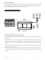
103T Digital Failsafe Starter Kill
What Is Included
■ 103T Control Module
■ 103T Keypad (see diagram below) with 4-Pin Keypad Harness
■ A Failsafe Starter Kill Relay
■ 5-Pin Main Harness
■ 2-Pin LED Interface Harness
■ 3-Pin Data Interface Harness
Product Description
The 103T Digital Failsafe Starter Kill is designed to be used as either a stand-alone passive/active starter kill or
as an interface to ESP systems that use a 3-pin data port. The 103T features an illuminated, dash-mounted
keypad, code-protected emergency override, and exit/entry Valet® code protection.
When used as a stand-alone starter kill, the 103T prevents the starter from cranking whenever the system is
armed. You can control the 103T’s basic functions from an the dash-mounted keypad. Simply enter coded key
sequences to control the starter kill functions.
The 103T can also be used as a serial controller for any of DEI’s ESP security systems. The ESP system LED can
be plugged into the 103T’s keypad port, so that the LED on the keypad functions as the main security system
LED. When connected to an ESP system, the 103T can be used to control Panic Mode, Valet® Mode and emergency
override.
© 2001 Directed Electronics, Inc.
1
N103T 2/01
Setting the Jumper
There is a single jumper inside the 103T control module that is used to determine whether the unit will be used
as a stand-alone starter kill or as an ESP interface. The jumper must be set prior to power-up.
To use the 103T as a stand-alone starter kill, you must leave the jumper on its pins, as originally packaged:
To use the 103T as an ESP interface, remove the jumper from its pins and discard:
© 2001 Directed Electronics, Inc.
2
N103T 2/01
5-Pin Main Harness Wire Connections
This section is provided as a reference for the main harness wire connections; however, not all of these wires will
need to be connected, depending on whether the 103T is being installed as a stand-alone starter kill or as an
ESP interface. Please read the installation instructions in the following sections before connecting these wires.
Red (+)12V With 5A Fuse
Connect the red wire to a fused constant 12V source in the vehicle, such as the 12V feed at the ignition switch
or the positive (+) battery terminal. If connecting this wire to the positive (+) battery terminal, make sure to
fuse as close to the battery as possible to protect the vehicle from damage in case of a short.
Black (-) Chassis Ground Connection
Connect this wire to bare metal, preferably with a factory bolt rather than your own screw. Screws tend to either
strip or loosen with time.
Yellow (+) Ignition Input
Connect this wire to the (+) 12V ignition wire. This wire must show (+)12V whenever the key is in the run or
crank positions.
Orange (-) Ground-When-Armed Output
This wire supplies a (-) 500 mA ground as long as the system is armed. This output ceases as soon as the system
is disarmed. The orange wire is used to control the starter kill relay.
© 2001 Directed Electronics, Inc.
3
N103T 2/01
Brown (-) Horn Honk Output
The brown wire supplies a (-) 200mA output that can be used to honk the vehicle's horn. If the 103T is armed,
this output is triggered if the ignition is turned on without the correct override code from the keypad. This output
can also be triggered if the panic feature is activated from the keypad.
103T Installation as a Stand-Alone Starter Kill
1. Plug the 4-pin keypad harness into the 103T module.
2. Next, plug the 5-pin main harness into the 103T module.
3. Before connecting power to the 103T, make sure the black 2-pin jumper is plugged into the jumper port of
the module.
4. Connect the red wire to a 5-amp fused constant 12V source in the vehicle, such as the 12V feed at the
ignition switch or the positive (+) battery terminal. If connecting this wire to the positive (+) battery
terminal, make sure to fuse as close to the battery as possible to protect the vehicle from damage in case of
a short.
5. Connect the black wire to bare metal, preferably with a factory bolt rather than your own screw. Screws tend
to either strip or loosen with time.
6. Connect the yellow wire of the 5-pin main harness plug and the yellow wire of the starter kill relay to the
main (+)12V ignition wire of the vehicle. This wire must show (+)12V whenever the key is in the run or crank
position.
© 2001 Directed Electronics, Inc.
4
N103T 2/01
7. Connect the orange wire of the 5-pin main harness plug to the orange wire of the starter kill relay. (See the
starter kill relay diagram below for the remaining starter kill relay connections.)
NOTE: When ordering a replacement starter kill, a DEI P/N 8618 starter kill can be used.
8. Connect the brown wire of the 5-pin main harness plug to the horn wire of the vehicle. If the vehicle has a
positive (+) horn circuit a relay will be required.
9. The LED interface plug is not used.
10. The data interface plug is not used.
NOTE: After connecting power to the unit, the system will come on in the armed mode. To disarm
the system, refer to the instructions in the 103T Owner's Guide.
© 2001 Directed Electronics, Inc.
5
N103T 2/01
103T Installation as a Serial Controller for an ESP System
1. Plug the 4-pin keypad harness into the 103T module.
2. Next, plug the 5-pin main harness into the 103T module.
3. Before connecting power to the 103T, make sure that the black 2-pin jumper is unplugged from the jumper
port. Discard the jumper.
4. Connect the red wire to a 5-amp fused constant 12V source in the vehicle, such as the 12V feed at the ignition switch or the positive (+) battery terminal. If connecting this wire to the positive (+) battery terminal,
make sure to fuse as close to the battery as possible to protect the vehicle from damage in case of a short.
5. Connect the black wire to bare metal, preferably with a factory bolt rather than your own screw. Screws tend
to either strip or loosen with time.
6. Connect the yellow wire of the 5-pin plug to the main (+)12V ignition wire of the vehicle. This wire must
show (+)12V whenever the key is in the run or crank position.
7. The orange wire not used.
8. The brown wire not used.
9. The starter kill relay is not used.
10. Plug one end of the 2-pin LED interface plug into the 103T module and the other end into the LED port of
the ESP system. The ESP system will now report all activity status and zone violations on the LED of the 103T
keypad.
11. Plug one end of the data interface plug into the data port of the 103T and the other end into the data port
of the ESP system.
© 2001 Directed Electronics, Inc.
6
N103T 2/01
Keypad Illumination
Pressing any button will illuminate the keypad. The illumination will time out 5 seconds after the last button is
pressed.
PIN code security
A personalized PIN code must be established to operate various functions of the 103T. A PIN code can range from
1 to 10 digits. Any digit may be repeated. The default PIN code from the factory is: 1234. Whenever the unit is
being taught a new PIN code, the keypad will control the LED, regardless of the jumper position.
To program a new, personalized PIN code:
1. Make sure the system is disarmed or in Valet Mode.
2. Turn on the ignition.
3. Enter the existing PIN code and the press
. (The LED will flash once.) EXAMPLE: To enter the factory
default PIN code of 1234:
1. Press
for 1.
2. Press
for 2.
3. Press
for 3.
4. Press
for 4.
7. Press
to enter the code.
4. Within 5 seconds, enter the new PIN code followed
. (The LED will flash twice.)
5. Within 5 seconds, enter the new PIN code again followed by
. (The LED will light solidly for 1 second.)
The new PIN code has been programmed. The programming mode is exited if the ignition is turned off or if there
is no activity for more than 5 seconds. If the PIN code programming mode is exited before a new PIN code is
set, the unit will default to the existing PIN code.
© 2001 Directed Electronics, Inc.
7
N103T 2/01