1
_/_
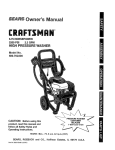
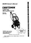
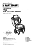
Owner's Manual
CRRFT$1dRN
°
5.0 HORSEPOWER
2000 PSI
2.2 GPM
HIGH PRESSURE WASHER
Model No.
580.762010
CAUTION:
PRESSURE WASHER
CUSTOMER
Before using this
HE.IPUNE
product, read this manual and
follow all Safety Rules and
Operating Instructions.
HOURS:
SEARS,
ROEBUCK
Pad No. 81849 Draft 0 (3/20/98)
Mon.-
and
Fri. 8 a.m. to 5 p.m. (CST)
CO.,
Hoffman
Estates,
IL 60179
U.S.A.
SAFETY RULES ............................
ASSEMBLY ..............................
4-5
OPERATION ............................
6-10
MAINTENANCE
........................
STORAGE
3
...............................
TROUBLESHOOTING
15
.......................
16
REPLACEMENT PARTS ..................
18-33
HOW TO ORDER PARTS ....................
11-14
34
LIMITED
ONE YEAR WARRANTY
ON CRAFTSMAN
HIGH PRESSURE
WASHER
For one year from the date of purchase, when this Craftsman High Pressure Washer is maintained and operated according to the instructions in the owner's manual, Sears will repair, free of charge, any defect in material
and workmanship.
If this high pressure washer is used for commercial purposes, this warranty applies for only 90 days from the
date of purchase. If this high pressure washer is used for rental purposes, this warranty applies for only 30
days after date of purchase.
This warranty does net cover:
• Expendable items such as spark plugs and air filters, which become worn during normal use.
•
Repairs necessary because of operator abuse or negligence, including damage resulting from no water being
supplied to pump or failure to maintain the equipment according to the instructions contained in the owner's
manual.
WARRANTY SERVICE IS AVAILABLE BY RETURNING THE HIGH PRESSURE WASHER TO THE
NEAREST SEARS SERVICE CENTER OR DEALER IN THE UNITED STATES.
This warranty gives you specific legal rights and you may also have other rights, which vary from state to
state.
SEARS,
ROEBUCK
AND CO., D/817 WA, Hoffman
2
Estates,
IL 60179
CAUTION: ALWAYS DISCONNECT SPARK PLUG WIRE AND PLACE WIRE WHERE IT CAN+
NOT CONTACT SPARK PLUG, TO PREVENT ACCIDENTAL STARTING WHEN SEI-rlNG UP,
TRANSPORTING, ADJUSTING OR MAKING REPAIRS TO YOUR HIGH PRESSURE WASHER.
---]
Never move the machine by pulring on the high pressure
hose. Use the handle provided on the top of the unit.
Keep the hose connected to machine or the spray gun
while the system is pressurized. Disconnecting the hose
while the unit is pressurized is dangerous.
Always be certain the spray gun, nozzles and accessories
are correctly attached.
read this manual and follow all Safety
CAUTION: Before using this product,
Rules and Operating Instructions.
Hold the spray gun firmly in your hand before you start the
unit. Failure to do so could result in an injury from a whipping spray gun. Do not leave the spray gun unattended
while the machine is running.
Never use a spray gun which does not have a trigger lock
or trigger guard in place and in working order.
Do not secure trigger gun in the puU-back(open) posiUon.
Keep water spray away from electdc wiring or fatal electdc
shock may resutt.
The cleaning area should have adequate slopes and
drainage to reduce the posaibiiity of a fall due to slippery
surfaces.
Engineexhaust gases containDEADLY carbon monoxide
gas. This dangerous gas, if breathed in sufficient concentrations, can cause unconsciousnessor even death.
Operate this equipment only in the open air where adequate ventilation is available.
Gasoline is highly FLAMMABLE andits vapors are
EXPLOSIVE. Do not permit smoking, open flames, sparks
or heat in the vicinity while handlinggasoline. Avoid
spilling gasoline on a hot engine. Allow unit to cool for 2
minutes before refueling. Comply with all laws regulaflng
storage and handling of gasoline.
The muffler and engine will heat up during operation and
remain hot immediately aftershutting it down. Avoid any
contact with a hot muffler or engine or you could be
severely burned.
Locate this pressure washer in areas away from any
combustiblematerials, combustiblefumes or dust.
Do not spray flammable liquids.
Some chemic_s or detergentsmay be harmful if inhaled
or ingested, causing severe nausea, fainting or poisoning.
These harmful elements may also cause propertydamage
or severe injury.
Use a respiratoror mask whenever there is a chance that
vapors may be inhaled. Read all instructionswith the mask
so you are certainthe mask will providethe necessary protecflonagainst inhaling harmfulvapors.
AJwayswear eye pmtectk_ when youuse this equipmentor
when youare in the vicin_.ywhere the equipmentis in use.
Do not wear loose clothing,jewelry or anythingthat may
be caught in the starter or other rotatingparts.
The high pressure equipment is designed to be used with
Sears authorized partsonly. If you use this equipment with
parts that do not comply with minimum specifications, the
user assumes all risks and liabilities.
Operate engine only at governed speed. Running engine
at excessive speeds increasesthe hazard of personal
injury. Do not tamper with parts which may increase or
decrease the governed speed.
Before starting the Pressure Washerin cold weather,
check all parts of the equipment and be sure ice has not
formed there.
The muffler and air cleanermust be installed and in good
condition before operating the Pressure Washer. These
components act as spark arrestors if the engine backfires.
Check fuel system for leaksor signs of daterioration such
as chafed or spongy hose, loose or missing clamps or
damaged tank or cap. Correct all defects before operating
the Pressure Washer.
Units with broken or missing parts, or without protective
housing or covers should NEVER be operated.
Do not adjust unloader valve to a pressurein excess of
machine raflng.
Operate the pressure at no more than the PSI fluid
pressure rated for your pressure washer.
High pressure spray can cause paint chips or other
particles to become airborne and fly at high speeds.
High pressure spray may damage fragile items including
glass. Do not point spray gun at glass when in the jet
spray mode.
A
A
Do not allow CHILDREN to operate the PressureWasher
at any time.
Never aim the gun at people, animals or plants.
This equipment produces high pressurestreams of fluid
which can pierce the skin and itsunderlying tissues,
leading to sehous injury and possible amputation.
Never allow any part of the body to come in contact with
the fluid stream. DO NOT come in contact with a fluid
stream created by a leak in the high pressure hose.
Do not by-pass any safety device on this machine.
MAINTENANCE
AND STORAGE:
Operate and storethis unit on a stable surface.
High pressure hose can developleaks from wear, kinking,
abuse, etc. Water spraying from a leak is capable of injecting material into skin. Inspect hoseeach Umebefore using
it. Check all hoses for cuts, leaks, abrasions or bulging of
cover,or damage or movement of couplings,if any of
these conditionsexist, replace hose immediately. Never
repairhigh pressure hose. Replace it with anotherhose
that meets minimum pressure rating of your pressure
washer.
IT
MEANS
YOUR SAFETY
IS INVOLVED."
LOOK
FOR"A'I-I'ENTION!!!
THIS SYMBOL BECOME
TO POINT ALERT!!!
OUT IMPORTANT
SAFETY
PRECAUTIONS.
3
I
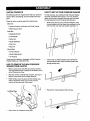
CARTON CONTENTS
HOW TO SET UP YOUR PRESSURE WASHER
The followingparts are shipped loose with your pressure
washer. Before assembling, become familiar with each
piece.
For the most part, your Craftsman High PressureWasher
has been assembled at the factory. You must, however,
attach the wire form, assemble the spray gun and attach
the high pressurehose to the pump and spray gun.
Check all carton contents against the listing below:
Main Unit:
•
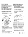
While facing the rear of the Pressure Washer, insert
the wire support with the longer arm positioned on the
left. From this view the hook should resemble a "J'.
•
Cut tie wrap on chemical injectiontube. Remove the
chemical injection filter, thread chemical injection tube
through the wire form.
• PressureWasher (w/wheels) and Guide Handle.
• High Pressure Hose
Parts Box:
• Adjustable Nozzle
• Turbo Nozzle
• Spray Gun
• Nozzle Extension
• Wire Form
• Motor Oil
Manual Bag:
• Owner's Manual
• Nozzle Cleaning Kit
• "O"-Ring Kit
If any parts are missing or damaged, call the Pressure
Washer Helpline at 1-800-222-3136.
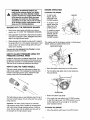
HOW TO REMOVE THE HIGH PRESSURE
WASHER FROM CARTON
Remove parts boxes included with pressure washer.
The high pressure hose is packed in the bottom of the
carton. Remove the hose.
Slice two comers at handle end of carton, from top to
bottom, so the panel can be folded down flat.
Raise handle, secure in place with the locking caps
(refer to illustration below) and roll the pressure
washer out the open end of the carton.
Locking Caps
•
Check carton for additionalloose parts.
Reinsert the chemical injectionfilter into tube.
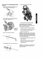
HOW TO SET UP YOUR PRESSURE
(continued)
WASHER
•
Cut the fie wraps on the High Pressure Hose and
connect to Spray Gun. Tighten by hand.
•
Remove plastic cap and connect High Pressure
Hose to Pump. Tighten by hand.
•
Place assembled spray gun on holder.
•
Place turbo nozzle in grommet hole in base.
PRE-OPERATIONAL
CHECKLIST
Before you operate your new high pressure washer
please review the following items:
Attach High
Pressure
Hose here
•
All assembly instructionshave been completed.
•
The high pressure hose connections to the spray
gun and to the pump are tight and secure.
•
Attach nozzle extension to spray gun.
Engine oil is at proper level
Important: Any attempt to crank or start the engine
before it has been serviced with the recommended oil
may result in an engine failure. See Page 9 for basic
instructions on adding oil and proper oil specifications
for your high pressure washer.
•
Be sure gas tank is filled properly with clean, fresh,
unleaded gasoline.
•
Become familiar with all controls - their location
and function. Operate those controls before
starting the engine.
Attach adjustable nozzle to the nozzle extension.
Important: The water supply to your high pressure
washer must be connected and turned on prior to
starting your engine.
.5
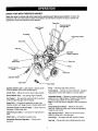
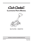
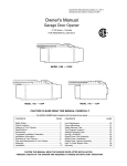
KNOW YOUR HIGH PRESSURE
WASHER
Read this owner's manual and safety rules before operating your high pressure washer. Compare the
illustrationswith your high pressure washer to familiarize yourself with the locationsof various controlsand
adjustments. Save this manual for future reference.
Spray Gun
High Pressure
Outlet
Chemical Injection
Tube and Filter
Air Cleaner
High Pressure Hose
Choke Rod
Gas CaP
Adjustable
Igni_on
.
Switch Lever
Inlet
-Pump
(wand)
Oil Pill Cap
Adjustable
Nozzle
Starter Grip
Ignition Switch Lever -- Sets engine in starting mode
for recoil starter and STOPS running engine.
Pump -- Develops high water pressure.
Turbo Nozzle -- Attaches to nozzle extension. Creates a
Choke Rod -- Adjusts for cold or warm engine startup.
high pressure stream that rotates in a circular pattern.
Recoil Starter Grip -- For starting engine manually.
Air Cleaner -- Dry type filter element limitsthe amount
of dirt and dust that gets into the engine.
Spray Gun -- Controls the applicationof water onto
cleaning surface with trigger device. Includessafety latch.
Chemical Injection Tube and Filter -- Mixes water and
detergent in outlet water flow.
High Pressure Outlet -- Connection for high pressure
hose.
Adjustable Nozzle -- Attaches to nozzle extension and
adjusts to low or high pressure. Twisting nozzle adjusts
the narrow spray pattern to a fan spray pattern.
Note: You can only siphon detergent in the low pressure
mode.
Nozzle Extension (wand) -- Attach one end to the
spray gun. Attach the other end to either the adjustable
nozzle or turbo nozzle.
High Pressure Hose -- Attach one end to the pump.
Attach the other end to the spray gun.
Water Inlet -- Connection for garden hose.
Oil Fill Cap -- Fill engine with SAE 10W-30 oil here.
Adjustable Pressure Regulator -- Adjusts water
pressure,
Gas Cap -- Fill gas tank with unleaded gasoline here.
HOW TO USE YOUR PRESSURE WASHER
•
-IF YOU HAVE ANY PROBLEMS operating your
pressure washer, please call the pressure washer
helpline at 1-800-222-3t 36.
A
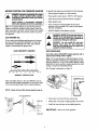
APPLYING DETERGENT AND CLEANING WITH
ADJUSTABLE NOZZLE
DANGER! NEVER adjust spray pattern I
when spraying. NEVER put hands in front
of spray nozzle to adjust spray pattem.
You could be injured.
[
HOW TO USE THE ADJUSTABLE NOZZLE
One of the nozzles you can attach to the nozzle
extension (wand) is the adjustable nozzle. You can
slide the adjustable nozzle forward and backward to
adjust the spray pattern to be either high or low pressure. You can also twistthe adjustable nozzle from
side to side to adjust the spray so it is concentrated in
a stream pattern or expanded into a fan pattern.
•
Slide the nozzle forward to adjust the spray to low
pressure mode. Slide the nozzle backward to
achieve high pressure.
Slide nozzle backward
for high pressure
mode.
If you get the spray nozzle too close, especially
using high pressure mode, you may damage the
cleaning surface.
Slide nozzle forward
for low pressure
mode.
Twisting the nozzle adjusts the spray pattern from
a narrow pattern to a fan pattern.
IMPORTANT: Use soaps designed specifically for
pressure washers. Household detergents could
damage the pump.
IMPORTANT: You must attach all hoses before you
start the engine. Starting the engine without all the
hoses connected and without the water tamed ON will
damage the pump.
To apply detergent follow these steps:
Prepare the detergent solution as required by the
job. (For the enclosed bottles of detergent, add the
8 ounces of chemical to a 1 gallon plastic bottle
with handle (not included). Fill the rest of the bottle
with water.)
•
Hang the detergent solution on the "J" hook on the
wire form on the guide handle.
•
Place small filter on the chemical injection tube
into the detergent container.
•
Slide adjustable nozzle forward to low pressure
mode. Detergent cannot be applied with nozzle
in high pressure position.
Note: The first step involves applying an appropriate
detergent/solvent solutionto penetrate and loosen
grime. The detergent is applied at low pressure to
avoid splashing, overspraying and waste. Leave the
solution on the surface for 3 to 5 minutes.
Review the use of the adjustable nozzle.
Connect garden hose to water inlet (see "TO
START PRESSURE WASHER"), check that high
pressure hose is connected to spray gun and
pump (see ASSEMBLY), and start engine.
For cleaning, start at lower portion of area to be
washed and work upward, using long, even,
overlapping strokes.
Twist nozzle counterclockwise for fan
Twist nozzle
clockwise for narrow
spray pattern,
spray pattern.
For most effective cleaning, keep the spray nozzle
between 8 to 24 inches away from the cleaning
surface.
Allow the detergent to soak in between 3 to 5
minutes before washing and rinsing.
Note: The second step involves cleaning the surface
you have prepared with the pressure washer and then
rinsing it clean.
A
ENGINE OPERATION
WARNING Be extremely careful if you
must use the pressure washer from ladder,
scaffolding or any other relatively unstable
location. Pressure in a running washer builds
in the wand as you climb. When you press
the trigger, the recoil from the initial spray
could force you to fall, or if you are too close
to the cleaning surface, high pressure could
force you off a climbing apparatus.
STARTING THE ENGINE
•
To start a cold
engine, pull the
choke rod to the
CLOSED position.
•
To restart a warm
engine, leave the
choke rod in the
OPEN position.
•
To restart an engine
that has just been
refueled, pull the
choke rod to the
CLOSED position.
•RINSING WITH THE PRESSURE WASHER
•
Hook up the water supply and start your pressure
washer (see TO START THE PRESSURE WASHER).
Slide adjustable nozzle back to high pressure position
and wait for detergent to clear. Detergent will not flow
when in the high pressure mode.
When detergent has cleared you may want to expand
the spray pattern for a more gentle rinsing action. Start
at top of area to be rinsed, working down with same
action as for cleaning.
CHOKE ROD
The engine used in the pressure washer is a fixed-speed
engine, utilizing an ignition Switch Lever.
IGNITIONSWITCHLEVER
You can also stop detergent from flowing by simply
removing the siphon from bottle.
HOW TO ADJUST PRESSURE USING THE
PRESSURE CONTROL KNOB
Located on the pump is a pressure control knob. You can
increase and decrease the pressure of the spray by turning the knob clockwise or counterclockwise respectively.
The knob is set at maximum pressure at the factory.
HOW TO USE THE TURBO NOZZLE.
Move the ignition switch lever to the ON position.
The turbo nozzle rotates the high pressure stream in a
rapid circular pattern. This increases the cleaning effectiveness of the high pressure spray. Attach the turbo
nozzle on the end of the nozzle extension.
•
Pull the starter grip lightly until you feel resistance,
then pull briskly.
STARTER
GRIP
Return the starter grip gently.
The high pressure spray is most effective when the tip of
the wand is held between 8 to 24 inches from the surface
if the choke rod was pulled to the CLOSED position
to start the engine, push it to OPEN position as soon
as the engine warms up enough to run smoothly.
(See illustration above)
being cleaned.
Important: The turbo nozzle produces an extremely
high pressure spray which is capable of removing paint
and cutting holes through cleaning surfaces if held too
close. Always make sure the surface you clean will not
be damaged by the high pressure spray.
STOPPING THE ENGINE
Move the ignition switch lever to the OFF position.
8
BEFORE STARTING THE PRESSURE WASHER
WARNING: Improperly maintainingthis engine
To operate the engine you will need to do the following:
•
Place pressure washer on a level surface.
•
Place ignitionswitch lever in STOP or OFF position.
could causea malfunctionin which you could be
Clean area around oil fill and remove oil dipstick.
serio lyiniuree.
Always perform a pre-operation inspection
beforeeach operationand correctany problem.
Note: It is important before you operate the pressure
washer to check the condition of the engine. Check for
signs of any gas or oil leaks. Check that all of the shields
and covers are in place, and all nuts, bolts and screws
are tightened.
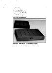
ADD ENGINE OIL
Oil is a major factor affecting performance and service
life. Use 4-stroke automotive detergent oil, rated with
API SERVICE classification SF or SG. SAE lOW-30
weight is recommended for general use.
SAE VISCOSITY
GRADES
•
Wipe dipstick clean.
•
Pour oil from the enclosed bottle into the oil fill
opening until oil reaches FULL mark on the dipstick.
DO NOT OVERFILL.
•
Install oil dipstick, hand tighten securely.
DANGER! NEVER fill the fuel tank indoors.
NEVER fill the fuel tank when the engine is
running or hot. DO NOT light a cigarette or
smoke when filling the fuel tank.
DANGER! Do not overfill the fuel tank.
Always leave room for fuel expansion.
Wipe any fuel spillage from the engine and
equipment before starting.
ADD GASOLINE
Use fresh, clean, UNLEADED regular gasoline with a
pump octane rating of 86 or higher.
Note: Do not use gasoline containing methanol (wood
alcohol). Gasoline containing up to 10% ethanol or grain
alcohol ("Gasohol"), or up to 15% MTBE (Methyl Tertiary
Butyl Ether) may be used but requires special care when
engine is unused for extended periods.
1QW=3O
See "Storage" instructions on Page 15.
="20 T 0 I 20 I 40 I 60 = 801100°_ F
-30 -20 -10
0
10
20
30
40°C
AMBIENT
TEMPERATURE
m
FUELLL=VFJ.
Other viscosities (shown in the chart ABOVE) may be
used when the average temperature in your area is within the recommended range. Use no special additives.
NOTE: Check oil level often during engine break in.
OIL FILLER
CAp/*DtPS'rlC
J(
Clean area around fuel fill cap, remove cap.
Slowly add "UNLEADED"regular gasoline to fuel tank.
Install fuel cap and wipe up any spilled gasoline.
IMPORTANT:
LOWER LIMIT
Never mix oil with gasoline.
HOW TO START YOUR PRESSURE WASHER
•
Move Ignition Switch Lever to the ON position.
You have assembled your high pressure washer and
have prepared the engine for starting. You are now ready
to clean your car, boat or whatever you plan to clean.
•
Positionthe nozzle in the low pressure mode (nozzle
slid forward) and squeeze the trigger on the spray
gun to relieve the air pressure caused by tuming ON
the water. Water will flow out of the gun in a thin
stream. Continue to hold trigger until you have a
steady stream of water and no air remains in the
system. This wilt make it easier to pull start the
engine. Release the trigger.
•
Engage the safety latch on the spray gun.
Place pressure washer in an area close enough to an
outside water source that flows at a rate of at least
2.5 gallons per minute. Connect a garden hose to the
water spout.
•
Check that high pressure hose is tightly connected to
spray gun and pump. See ASSEMBLY section.
•
Pull back on the locking collar to remove the female
quick-connect from pump.
Assembled
Quick-Connect
Grasp the starter grip handle and pull slowly until you
feel some resistance. Then pull rapidly to start the
engine.
Return the starter grip handle slowly.
Pull back on locking
collar to separate
TO STOP YOUR PRESSURE WASHER
Disassembled
male end
•
•
Wait for the engine to idle down.
•
Simply shutting off the engine will not release
pressure in the system. Squeeze trigger on the
spray gun to relieve pressure in the hose.
Note: A small amount of water will squirt out from the
spray gun when you release the pressure.
Check inlet screen. If screen is dirty, clean before
attaching to garden hose. If screen is damaged,
Do not connect to garden hose. Replace with the
inlet screen provided in the O-ring kit or call 1-800366-PART to order a replacement (p/n B2384).
SIPHONING
We recommend that you DO NOT siphon standing water
for your water supply. Contaminated, brackish or dirty
water can damage the pump. Connect only to household
water supply.
Attach the female quick-connect to garden hose and
then attach the garden hose to the water inlet.
Make sure the quick-connect
Move the Ignition Switch Lever to the OFF position.
female end
Note: You will also need to pull back on the locking
collar to attach the female quick-connect.
•
•
is locked together.
Tum on the water.
TIPS
Note: Do not run pump without the water supply
connected and turned on. You must follow this
caution or the pump will be damaged.
•
Never use the garden hose inlet to siphon detergent
or wax.
•
If you have the spray nozzle too far away, cleaning
will not be as effective.
Position the Choke Rod according to the starting
recommendations on page 8:
• Cold engine
(Choke-CLOSED)
• Restarted warm engine
(Choke-OPEN)
• Just refueled engine
(Choke-CLOSED).
/o
CUSTOMER
RESPONSIBILITIES
MAINTENANCE SCHEDULE
FILL IN DATES AS YOU COMPLETE
REGULAR SERVfCE
MAINTENANCE
HOURLY OPERATING INTERVAL
Before Each
Use
TASK
Every 25
Hours or
Yeady
SERVICE DATES
Every 100
Hours or
Yearly
PRESSURE WASHER
Check/clean water inletscreen
on quick-connect.
xt
Check high pressure hose.
x
Check detergent hose,
x
Check spray gun and assembly for leaks.
x
Purge pump of air and contaminants.
x
ENGINE
x
Check oil level
x*
Change engine oil.
x**
Service air cleaner.
x
Clean/replace spark plug.
Prepare unitfor storage if it is to
remain]drefor longerthan 30 days.
Prepare for storage.
t Clean if clogged. Replace if perforated or tom.
• Change oil after first 2 hours then 25 thereafter. Change sooner when under dirty or dusty conditions.
" Clean more often under dirty or dusty conditions.
GENERAL
RECOMMENDATIONS
Engine Specifications
The warranty of the high pressure washer does not cover
items that have been subjected to operator abuse or negligence. To receive full value from the warranty, operator
must maintain high pressure washer as instructed in this
manual.
ENGINE MODEL
HONDA
RATED HORSEPOWER
5.0
DISPLACEMENT
160cc
SPARK PLUG: Type:
Some adjustments will need to be made periodically to
properly maintain your high pressure washer.
Set Gap to:
All adjustments in the Service and Adjustments section of
this manual should be made at least once each season.
NGK: BPR6ES
or equivalent
0.028-0.031 in.
(0.70-0.80mm)
GASOLINE
Once a year you should clean or replace the spark
plug and clean or replace the air filter and check the
gun and wand assembly for wear. A new spark plug
and clean air filter assure proper fuekair mixture and
help your engine run better and last longer.
CAPACITY
1.8 U.S. quart
OIL
SAE 10W-30 weiqht
SOLID STATE IGNITION
AIR GAP
0.0125 inch
PRODUCT SPECIFICATIONS
Pressure Washer Specifications
PRESSURE
2000 psi
FLOW RATE
2.2 GPM
.DETERGENT M X
WATER SUPPLY
TEMPERATURE
In the State of California a spark arrestor is required by
law (Section 4442 of the Califomia Public Resources
Code). Other states may have similar laws. Federal laws
apply on federal lands.
Note: if you equip the engine of your pressure washer with a
spark arrestor muffler, the spark arrestor must be maintained in
effective working order by the owner/operator.
Use undiluted deterqent
Not to Exceed 140°F
You can order a spark arrestor throughyour Sears Service
Center.
1!
BEFORE
•
•
•
•
•
EACH
ENGINE MAINTENANCE
USE
Check water inlet screen for damage.
CHECKING OIL LEVEL
Check high pressure hose for leaks.
Check detergent inlet hose and filter for damage.
Check gun and wand assembly for leaks.
Purge pump of air and contaminants.
Check engine oil level
Oil level should be checked before each use, and at least
after every 5 hours of operation as follows:
PRESSURE
WASHER
MAINTENANCE
•
Check the engine oil level with the engine stopped
and in a level position.
•
Remove the oil filler cap/dipstick and wipe it clean.
•
Insert and remove the dipstick without screwing it into
the filler neck. Check the oil level shown on the dipstick.
•
If the oil level is low, fillto the edge of the oil filler hole
with the recommended oil. (See page 11)
•
Reinstall the oil filler cap.
CHECK AND CLEAN INLET SCREEN
Remove quick-connect and examine inlet screen on the
female connector. Clean if clogged or replace if torn.
CHECK HIGH PRESSURE HOSE
High pressure hose can develop leaks from wear, kinking
and abuse. Inspect hose before each use. Check for cuts,
leaks, abrasions or bulging of cover, or damage or movement of couplings. If any of these conditions exist,
replace hose immediately.
I_i,
capable of injecting material into skin.
NEVER repair high pressure hose. Replace
with
hose that
meets
minimum
DANGER:
Water
spraying
frompressure
a leak is
rating of your pressure washer.
CHECK DETERGENT HOSE
Examine the filter on the hose and clean if clogged. Hose
should fit tightly on barbed fitting. Examine for leaks or
tears. Replace the filter or hose if either is damaged.
CHANGING ENGINE OIL
Change engine oil after first 2 hours then every 25 hours
thereafter. If you are using your pressure washer under
extremely dirty or dusty conditions, or in extremely hot
weather, change the oil more often.
Drain used oil while engine is warm. Warm oil drains
quickly and completely.
•
Disconnect spark plug wire from spark plug and keep
it away from spark plug.
•
Place a suitable container below pressure washer
base to catch used oil. Tilt the pressure washer.
Remove oil filler cap/dipstick and drain plug.
OIL RU._
CAP/DIPSTICK
CHECK SPRAY GUN AND WAND
Examine hose connection to spray gun and make sure it
is secure. Test trigger by pressing it and making sure it
spdngs back into place when released. Put the safety
latch in the UP positionand test trigger. You should not
be able to press the trigger.
PURGE PUMP OF AIR AND CONTAMINANTS
To remove the air from the pump:
)RAIN PLUG
•
Set up the pressure washer as described in the
ASSEMBLY section and connect the water supply.
•
Remove the nozzle extension from the spray gun.
Pull the trigger on the gun and hold.
Allow the used oil to drain completely, then reinstall
the drain plug, and tighten securely.
To remove contaminants from the pump:
•
Set up the pressure washer as described in the
ASSEMBLY section, and connect the water supply.
•
Remove the nozzle attachment from the spray gun.
Dispose of used motor oil in a manner that is compatible with the environment. We suggest you take used
oil in a sealed container to your local recycling center
or service station reclamation center. Do not throw it
in the trash, pour it on the ground, or down a drain.
Start engine according to OPERATION instructions.
Pull the trigger on the spray gun and hold.
With the engine in a level position, fill the engine with
new oil to the outer edge of the oil filler hole and
screw in the oil filler cap/dipstick securely.
When the water supply is steady, engage the safety
latch and refasten the nozzle attachment.
12
SERVICING THE AIR CLEANER
CLEAN/REPLACE SPARK PLUG
Your engine will not run properly and may be damaged
if you run it with a dirty air cleaner.
Change the spark plug every 100 hours of operation or
once each year, whichever comes first. This will help
your engine to start easier and run better. Replace with
NGK: BPR6ES or equivalent type spark plug.
Replace air cleaner once every 100 hours of operation
or once each year, whichever comes first.
Replace more often if operating under dirty or dusty
conditions. Replacements are available at your local
Sears Authorized Service Center.
•
Disconnect the spark plug cap and remove any dirt
from around the spark plug area.
•
Remove the spark plug with a 13/16-inch spark plug
wrench.
Important: Operating your pressure washer without
a complete air cleaner installed will allow dirt to enter
the engine, causing rapid engine wear. This type of
damage is not covered by warranty.
Inspect spark plug and replace if electrodes are worn
or if the insulator is cracked or chipped.
Clean with a wire brush if you are going to reuse it.
Measure the spark plug electrode gap with a suitable
gauge. Correct the gap, if necessary, by carefully
bending the side electrode. Set gap at 0.028-0.031 in.
(0.70-0.80ram).
To clean or replace the air cleaner, follow these
steps:
Press the latch tabs on fuel tank side of air cleaner
cover, and remove cover. Check filter to be sure it is
clean and in good condition.
AIR CLEANER COVER
!
,I
Install spark plug carefully, by hand, to avoid crossthreading. Tighten with spark plug wrench to compress the washer. (Used plug - 1/8 to 1/4 turn; New
plug - 1/2 turn)
LA_:HTABS
AIR CLEANER BODY
Attach the spark plug cap.
AIR DUCT
"rA_
NOZZLE MAINTENANCE
If the nozzle becomes restricted or clogged with foreign
materials, such as dirt, excessive pump pressure may
develop. A partially clogged nozzle can cause a pulsing
sensation during use. This generally is not pump related,
but rather clue to a clogged or partially restricted nozzle.
If you feel this pulsing during use, it is recommended you
immediately clean the nozzle. Use the kit included with
your pressure washer, and follow these instructions:
Replace the filter if it is damaged.
if filter is dirty, clean it by tapping it several times
on a hard surface to remove any dirt. You may also
blow compressed air [(not exceeding30 psi (207 kPa,
2.1 kg/crn*)]through the filter from the clean side that
faces the engine.
Shut off engine and turn off the water supply.
Never try to brush off dirt. Brushing will force dirt into
the filter fibers.
Wipe dirt from the air cleaner body and cover, using
a moist rag. Be careful to prevent dirt from entering
the air duct that leads to the carburetor.
Insert a new or cleaned filter.
Replace cover. Push tabs into slots until they "click".
]3
•
Separate the nozzle from the nozzle extension.
•
Rotate to the stream setting.
•
Remove orifice from the end of the nozzle using the
allen wrench included with the kit or with a 2mm or
5/64 allen wrench.
Use the wire included in the kit or a small paper clip
to free the foreign materials clogging or restricting the
nozzle.
Insert wire into the nozzle orifice, and tum it
back and forth to clear any obstruction.
Remove additional debris by back flushing water
supply through wand. Back flush between 30 to 60
seconds. Turn wand to stream spray and move
nozzle from low to high pressure while flushing.
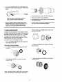
O-RING
•
Reinstall orifice into nozzle. DO NOT overtighten.
•
Reconnect nozzle to nozzle extension.
•
Reconnect with the water supply, turn ON the water
and start the engine.
•
Test the pressure washer by operating with nozzle in
the high and the low pressure positions.
•
MAINTENANCE
1 Rubber Washer (p/n B2385) for the inside of the
Male Quick-Connect.
Through the normal operation of your pressure washer,
O-Rings, which keep the connections of the hoses and
gun tight and leak-free may become worn or damaged.
Provided with your pressure washer is an O-Ring
Maintenance Kit which provides replacement O-Rings,
Rubber Washer and Quick Connect filter.
To remove a worn or damaged O-Ring:
•
Use a small flathead screwdriver to get underneath
the O-Ring and pry it off.
•
Parts in the O-Ring Kit Include:
•
1 O-Ring (p/n B2386) for the outside of the Male
Quick-Connect.
2 O-Rings (p/n B2726) for each end of the nozzle
extension.
O
•
2 O-Rings (p/n B2264) for the ends of the high
pressure hose.
0
NOTE: THE ABOVE TWO O-RiNGS ARE CLOSE IN SIZE.
Please match carefully to assure proper O-Ring usage.
]4
1 Water Inlet Screen (p/n B2384) for the Female
Quick-Connect.
Note: To avoid engine problems, the fuel system should
be emptied before storage of 30 days or longer.
Follow these instructions:
AFTER EACH USE
Water should not remain in the unit for long periods of time.
Sediments of minerals can deposit on pump parts and
"freeze" pump action. Follow these procedures after every
PROTECT FUEL SYSTEM
use:
•
Flush detergent hose by placing the injector filter into
a pail of clear water while running Pressure Washer
with nozzle in tow pressure mode. Flush until you can
see clear water running through the tube.
,_
Shut off the engine and let it cool, then remove all
hoses.
DANGER:
Drainaway
fuel from
into approved
container
outdoors,
open flame.
Be
sure engine is cool. Do not smoke.
Run engine until engine stops from lack of fuel. Make
sure you have water supply to pump inlet connected
and turned ON.
CAUTION; Be sure ignition switch lever is
in "STOP" position before you continue. If
you start engine without the proper water
supply connected, you can damage the
pump.
Note: If "Gasohol" has been used, complete above
instructions and then put 1/2 pint of unleaded gasoline
into fuel tank and repeat above instructions.
Empty the pump of all pumped liquids by pulling recoil
handle about 6 times. This should remove most of the
liquid in the pump.
Note: Fuel stabilizer (such as STA-BIL) is an acceptable
alternative in minimizing the formation of fuel gum
deposits during storage. Add stabilizer to gasoline in fuel
tank or storage container. Run engine at least 10 minutes
after adding stabilizer.
Coil the high pressure hose and inspect it for damage.
Cuts in the hose or fraying of it could result in leaks
and loss of pressure. Should any damage be found,
replace hose. DO NOT attempt to repair a damaged
hose. Replace hose with the genuine Craftsman part.
CHANGE OIL
Drain water from hose and properly hang it on the
wire support provided on the guide handle.
While engine is still warm, drain oil from crankcase, Refill
with recommended grade. (See Changing Oil Level on
Page 12.)
Store in a clean, dry area.
OIL CYLINDER BORE
•
A
DANGER: NEVER store engine with fuel in
tank indoors or in enclosed, poorly ventilated areas where fumes may reach an open
flame, spark or pilot light as on a furnace,
water heater, clothes dryer or other gas
appliance.
from freezing temperatures. Failure to do so
will
permanently
your your
pumpunit
and
CAUTION:
You damage
must protect
render your unit inoperable.
I,_
WINTER
Remove spark plug and squirt about 1 ounce (30 ml)
of engine oil into the cylinder. Cover spark plug hole
with rag. Crank slowly to distribute oil.
,_
•
CAUTION:
Avoid spray
fromslowly.
spark plug
hole when cranking
engine
install spark plug. Do not connect spark plug wire.
OTHER
Do not store gasoline from one season to another.
STORAGE
Replace your gasoline can if your can starts to rust.
Rust and/or dirt in your gasoline will cause problems.
To protect the unit from freezing temperatures:
•
Remove all gasoline from the fuel tank to prevent gum
deposits from forming on these parts and causing
possible malfunction of engine.
If possible, store your unit indoors and cover it to give
protection from dust and dirt. BE SURE TO EMPTY
THE FUEL TANK.
Draw RV antifreeze (antifreeze without alcohol) into
the pump by pouring the washer fluid into a 3-foot
section of garden hose connected to the inlet adapter
and pulling the recoil handle twice.
•
LONG TERM STORAGE
Cover your unit with a suitable protective cover that
does not retain moisture.
IMPORTANT: NEVER cover your pressure washer while
engine and exhaust area are warm.
If you do not plan to use the Pressure Washer for more than
30 days, you must prepare the engine for long term storage.
Note: As always, prepare the pressure washer pump as
you would after each use.
15
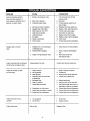
PROBLEM
CAUSE
CORRECTION
Pump has following problems:
Nozzlein low pressuremode.
1.
Pull nozzle backward for high
erratic pressure, chattedng, loss of
2.
Water inlet is blocked.
2.
pressure mode.
Clear inlet.
pressure, lowwater volume.
3.
Inadequate water supply.
3.
Provide adequate water flow at
4.
Inlet hose is kinked or leaking.
4.
Straighten inlet hose, patch leak.
5.
Clogged water inlet screen.
5.
Replace / clean water inlet screen.
6.
7.
Water supply is over 140°F.
Outlet hose is blocked.
6.
7.
Provide cooler water supply.
Clear blocks in outlet hose.
8.
Outlet hose leaks.
8.
Replace outlet hose if leaking.
9.
Gun leaks.
10. Nozzle is obstructed.
9. Replace o-dng or gun if necessary.
10. Clear nozzle.
11. Pump is faulty.
11. Contact Sears Service Department.
failure to produce pressure, or
least 2.5 gpm.
Detergent fails to mix with
1.
Detergent line is not submerged
1.
insert chemical line into detergent.
in detergent spray.
spray.
2.
Chemical filter is clogged.
2.
Clean or replace filter/detergent
line.
3.
Nozzle is in high pressure mode.
3.
Push nozzle forward for
low pressure mode.
Engine runsgood when not spraying
Engine speed is too slow.
Contact Sears Service Department.
but dies when you begin to spray.
1. Clean or replace air cleaner.
Fill fuel tank.
Engine will not start; or starts
1.
Dirty air cleaner
and runs rough.
2.
3.
Out of gasoline.
2.
Stale gasoline.
3.
Drain gas tank; fill with fresh fuel.
4.
Spark plug wire not connected
4.
Connect wire to spark plug.
to spark plug.
5.
Bad spark plug.
5.
Replace spark plug.
6.
Water in gasoline.
6.
Drain gas tank; fill with fresh fuel.
7.
Overchoking or flooded.
7.
Set engine throttle control lever to
fast position, choke in run position.
8.
Excessively rich fuel mixture.
9.
Intake valve stuck open or closed.
10. Engine has lost compression.
8.
Contact Sears Service Department.
9.
Contact Sears Service Department.
10. Contact Sears Service Department.
Engine shuts down during
1.
Out of gasoline.
1.
Fill fuel tank.
operation.
2.
Air filter didy
2.
Replace Air filter.
Engine lacks power.
Dirty air filter.
Replace air filter.
I6
17
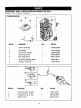
CRAFTSMAN
HONDA
2000
4-Cycle
CYLINDER
PSI HIGH PRESSURE WASHER
Engine
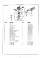
580.762010
GC160
BARREL
I--
4
Ref No.
1
2
Cylinder Assembly
Clip, Valve Guide
1
1
12000-ZL8-000
12216-ZE5-300
3
4
Cover, Head
1
1
12311-ZL8-000
12355-ZL8-000
4
90013-883-000
90014-952-000
5
6
7
8
9
Cover Comp., Breather
Bolt, Flange (6x12)
1
1
1
Bolt, Flange (6x14)
OU Seal (25.4x62x6)
Spark Plug (BPR6ES) (NGK)
Guide, Ex. Valve (OS)
1
91201-ZL8-003
98079-56846
12205-ZE1-315
CRANKSHAFT
-®
.
®
o._____,.
Ref N
Description
_.
Part No.
1
2
Crankshaft Gomp. (Q-Type)
Crankshaft Comp. (P-Type)
1
13310-ZL8-600
1
13310-ZL8-650
3
Crankshaft Comp. (V-Type)
Washer, Thrust
1
1
13310-ZL8-670
90402-ZL8-000
4
18
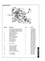
:RANKCASE
COVER
E-_741
10
18
8
Ref No.
1
2
3
4
5
6
7
8
9
10
11
Cover Assembly,
Crankcase (Q-Type)
Cover Assembly,
Cover Assembly,
Crankcase (U-Type)
Crankcase (UX-Type)
Gasket, Oil Filler Cap
etv.
Part No.
1
1
11300-ZL8-600
1
1
1
Gauge Assembly, Oil Level
Governor Assembly
1
2
Weight, Governor
Holder, Governor Weight
1
2
Pin, Governor Weight
Slider, Governor
Shaft, Governor Arm
1
1
8
Bolt, Flange (67,25)
Bolt, Drain Plug
2
1
11300-ZL8÷660
11300-ZL8-670
15625-ZE1-003
15650-ZL8-003
16510-ZL8-000
16511-ZL8-000
16512-ZL8-000
16513-ZE1-000
16531-ZE1-000
165421-ZL8-000
90121-952-000
90131-883-000
90131-883-000
90131-896-650
Bolt, Drain Plug
2
Washer, Thrust (6MM)
1
1
90131-896-650
12
13
14
Clip, Governor Holder
1
Bearing, Radial Ball
Oil Seal (28x41.25x6)
1
90602-ZE1-000
91001-ZL8-003
15
16
17
Washer, Plain (6MM)
Washer, Drain Plug (12MM)
18
Pin, Lock (8MM)
19
Pin, Dowel (8x20)
1
2
2
1
1
2
]9
90451-ZE1-000
91202-ZL8-003
941O1-068OO
94109-12000
94109-12000
94251-08000
94301-08200
PISTON
o
[
1
--4
Part No.
Ref No.
Description
1
Ring Set, Piston (Riken)
Ring Set, Piston (Teikoku)
Piston
2
3
4
5
Pin, Piston
Rod Assembly, Connecting
Bolt, Connecting Rod
Clip, Piston Pin (13MM)
6
1
1
13010-ZL8-003
13010-ZL8-004
1
1
13101-ZL8-000
13111-ZE0-000
1
2
2
13200-ZL8-000
90001-ZE1-000
90551-ZE0-000
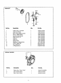
FAN COVER
2
Ref No.
Descrintion
1
Cover, Fan _NHI*
2
Bolt, Stud
3
Nut, Flange (6MM)
(Black)
2O
ew.
Part No.
1
19611-ZL8-000ZA
3
3
90043-ZL8-000
90303-MR1-000
CAMSHAFT
O'-12
':-i'F
Ref No.
1
Pulley Comp., Camshaft
1
2
Shaft, Cam Pulley
Belt, Timing (84HU7 G-200)
Arm, In. Valve Rocker
Arm, Ex. Valve Rocker
Shaft, Rocker Arm
Valve, In.
Valve, Ex.
Spring, Valve
Retainer, In. Spring Valve
Screw, Tappet Adj,
Nut, Tappet Adj.
O-Ring (6.8xl .9)
1
14320-ZL8-000
14324-ZL8-000
1
1
1
2
1
1
2
2
2
2
1
14400-ZL8-003
14431-ZL8-000
14441-ZL8-000
14461-ZL8-000
14711-ZL8-000
14721-ZL8-000
14751-ZL8-000
14771-ZE1-000
90012-333-000
90206-001-000
91306-PJ4-000
3
4
5
6
7
8
9
10
11
12
13
RECOIL STARTER
Ref No.
Description
1
8
Starter Assy., Recoil *NHI*
Knob, Recoil Starter
1
1
28400-ZL8-003ZA
28461-ZL8-003
9
Rope, Recoil Starter
1
28462-ZL8-003
Part No.
2]
CARBURETOR
12
11
J
18--
Pa_ No.
Ref No.
1
2
Gasket Set
Float Set
3
4
Chamber Set, Float
Screw Set
5
6
Screw Set, Drain
Screw Set B
7
8
9
Screw Set
Carburetor Assy. (BB61B B)
10
11
Valve Comp., Float
Nozzle, Main
Insulator, Carburetor
12
13
Gasket, Insulator
Gasket, Carburetor
14
15
Gasket, Carburetor (Choke side)
16
17
18
16010-883-015
1
1
16013-ZL1-003
16015-ZL8-003
1
1
16016-ZG0-W00
16024-124-760
1
1
16028-ZE0-005
16029-ZG0-901
1
1
1
16100-ZL8-801
16155-ZL8-003
1
1
2
1
1
Guide Comp., Air
Screw, Pan (5x6)
1
1
Clip, Tube (B6.5)
Bulk Hose, Vinyl (4x7xS000)
1
(4x7x150)
19
1
Jet, Main (#60)
Jet, Main (#62)
1
Jet, Main (#65)
1
(1)
22
16166-ZL8-003
16211-ZL8-000
16212-ZL8-000
16221-883-800
16288-ZL8-000
19650-ZL8-000
93500-05006-1H
95002-02650
95003-07008-60M
99101-124-0600
99101-124-0620
99101-124-0650
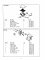
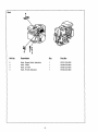
AIR CLEANER
Ref No.
Description
1
Part No.
Tube, Breather
1
2
Element, Air Cleaner
1
15721-ZL8-000
15721-ZL8-000
3
4
5
Housing Comp., Air Cleaner
Gasket, Air Cleaner
Cover, Air Cleaner
1
1
17220-ZL8-000
17228-ZL8-000
6
Bolt, Flange (6xl 12) (CT200)
1
2
17231-ZL8-000
90003-ZL8-000
MUFFLER
?
Ref No.
Descrigtion
1
Muffler Comp.
Protector, Muffler
2
Part No.
Protector, Muffler
3
4
5
6
7
8
Arrestor Comp., Spark
Plate, Arrester Number
Shroud, Muffler
1
18310-ZL8-010
1
1
18321-ZL8-A00
18321-ZL8-000
1
1
18350-ZL8-000
1
2
Bolt, Flange (6x79) (CT 200)
Bolt, Flange (6x12)
3
Screw, Tapping (4x6)
23
18356-ZL8-000
19664-ZL8-000
90004-ZL8-000
2
90013_883-000
90055-ZE1-000
3
90055_ZE1-000
2
®
13
Ref No.
Description
1
2
3
4
5
Pump Assy., Fuel
Rubber, Supporter (107MM)
Tube, Diaphragm
Filter, Fuel
Tank, Fuel
Tank, Fuel
Rubber B, Tank Mounting
Joint, Fuel Tube
Collar, Fr. Cover Setting
Stay A, Fuel Tank
Cap Assy., Fuel Tank
Tube, Fuel Tank
Tube, Fuel
Tube, Fuel
Tube, Fuel Return
Rubber, RR. Fender
6
7
8
9
10
11
12
13
14
15
16
17
18
19
20
21
23
Bolt, Stud (F/Tank)
Washer (8MM)
Collar (14x6.1 )
Bolt-Washer (6x25)
Screw-Washer (5x14)
Nut, Flange (6MM)
Clip, Tube (BS)
24
Clip, Tube (BIO)
25
26
27
Clip, Tube (C9)
Clip, Tube (C11)
Bulk Hose, Fuel (5.5x8000)
(5.5x33)
Filter Comp., Fuel
Suspension, Strainer
Tube, Fuel Tank
Tube, Fuel Pump
28
29
30
31
Pad No.
24
1
1
1
1
1
1
2
1
1
1
1
1
1
1
1
1
1
1
2
2
2
1
1
3
1
5
1
1
16700-ZL8-003
16854-ZH8-000
16882-ZL8-000
16952-ZA8-800
17511-ZL8-000
17511-ZL8-800
17516-ZV0-000
17519-ZL8-800
17535-166-000
17561-ZL8-000
17620-ZL8-003
17701-ZL8-000
17702-ZL8-000
17702-ZL8-800
17703-ZL8-800
80103-MG2-000
90041-ZL8-000
90473-896-000
90501-KA2-640
93404-06025-00
93894-05014-00
94050-06000
95002-02080
95002-02080
95002-02100
95002-02100
95002-50000
95002-70000
1
1
1
1
1
95001-55008-40M
16910-ZV4-015
16915-ZV4-000
17701-ZL8-800
17704-ZL8-800
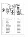
-'LYWHEEL & IGNITION COIL
18
Ref N_
Descr_
Part No.
1
Key, Special Woodruff (25x18)
1
13331-357-000
2
Coil Assy., Ignition
1
30500-ZL8-004
3
Clamp, Stop Switch Wire
1
30548-ZL8-000
4
Clamp, Wire
1
30549-ZL8-000
5
Flywheel Comp.
1
31110-ZI8-004
6
Wire, Stop Switch
1
32195-ZL8-000
7
Wire, Stop Switch
1
32195-ZL8-810
8
Protector, Switch
1
35419-ZL8-000
9
Switch Comp., Oil Level
1
35480-ZL8-811
10
Holder, Stop Switch Wire
1
36103-ZE1-000
11
Bolt, Flange (6x12)
3
90013-883-000
12
Bolt, Flange (6x14)
1
90014-952-000
13
Bolt, Flange (6x28)
1
90015-883-000
14
Bolt, Flange (6x20)
1
90022-888-010
15
Nut, Special (14MM)
1
90201-878-003
16
O-Ring (11.8x2.4)
1
91320-MJ6-003
17
Collar (6.6xl 3.8x14.5)
1
91501-ZL8-000
18
Sensor Unit ESS
1
34150-ZH7-003
25
CONTROL(I)
2_
Ref No.
Part
1
Control Assy.
1
16500-ZL8-000
2
Arm, Governor
1
16551-ZL8-000
3
Rod, Governor
1
16555-ZL8-000
4
Spring, Governor
1
16561-ZL8-000
5
Spring, Throttle Return
1
16562-ZL8-000
6
Lever, Control
1
16571-ZL8-000
7
Spring, Lever
1
16574-ZE1-000
8
Washer, Control Lever
1
16575-ZL8-000
9
Spacer, Control Lever
1
16578-ZE1-000
10
Base Comp., Control
1
16580-ZL8-000
11
Rod, Choke Control
1
16611-ZL8-000
12
Grommet, Choke Rod
1
16613-893-000
13
Plate, Side
1
19612-ZL8-000
14
Switch Assy., Engine Stop (N.O)
1
35120-ZL8-003
15
Bolt, Flange (6x12)
1
90013-883-000
16
Bolt, Flange (6x14)
2
90014+952-000
17
Bolt, Governor Arm
1
90015-ZE5-010
18
Nut, Self-lock (6MM)
1
90114-SA0-000
19
Screw-Washer (4x12)
1
93892-04012-00
20
Nut, Flange (6MM)
1
94050-06000
21
Washer, Plain
1
94103-04000
26
CONTROL(2)
No.
Ref No.
Description
1
Control Assy.
1
16500-ZL8-800
2
Arm, Governor
1
16551-ZL8-000
3
Rod, Governor
1
16555-ZL8-000
4
Spring, Governor
1
16561-ZL8-000
5
Spring, Throttle Return
1
16562-ZL8-000
6
Lever, Control
1
16571-ZL8-800
7
Washer, Control Lever
1
16575-ZL8-800
8
Holder, Cable
1
16576-891-000
9
Spacer, Control Lever
1
16578-ZL8-800
10
Base Comp., Control
1
16580-ZL8-000
11
Rod, Choke Control
1
16611-ZL8-000
12
Grommet, Choke Rod
1
16613-893-000
13
Plate, Side
1
19612-ZL8-000
14
Switch Assy., Engine Stop (N.O)
1
35120-ZL8-003
15
Bolt, Flange (6x12)
1
90013-883-000
16
Bolt, Flange (6x14)
2
90014-952-000
17
Bolt, Governor Arm
1
90015-ZE5-010
18
Nut, Self-lock (6MM)
1
90114-SA0-000
19
Washer (12.5MM)
2
90452-KG8-000
20
Screw, Pan (5x16)
1
93500-05016-0A
21
Screw-Washer (4x12)
1
93892-04012-00
22
Nut, Flange (6MM)
1
94050-06000
23
Washer, Plain (4MM)
1
94103-04000
2?
CONTROL(3)
2_
Ref No.
Descr_r_r_@tion
Part No.
1
Control Assy.
1
16500-ZL8-850
2
Arm, Governor
1
16551-ZL8-000
3
Rod, Govemor
1
16555-ZL8-000
4
Spring, Governor
1
16561-ZL8-810
5
Spring, Throttle Return
1
16562-ZL8-000
6
Lever, Control
1
16571-ZL8-850
7
Spring, Lever
1
16574-ZE1-000
8
Washer, Control Lever
1
16575-ZL8-000
9
Spacer, Control Lever
1
16578-ZE1-000
10
Base Comp., Control
1
16580-ZL8-000
11
Spring, Control Adjusting
1
16584-883-300
12
Rod, Choke Control
1
16611-ZL8-000
13
Grommet, Choke Rod
1
16613-893-000
14
Lever, Stop
1
16631-ZL8-000
15
Plate, Side
1
19612-ZL8-000
16
Switch Assy., Engine Stop (N.O)
1
35120-ZL8-003
17
Bolt, Flange (6x12)
1
90013-883-000
18
Bolt, Flange (6x14)
2
90014-952-000
19
Bolt, Governor Arm
1
90015-ZE5-010
2O
Screw, Adjust
1
90031-ZL8-850
90114-SA0-000
21
Nut, Self-lock (6MM)
1
22
Washer, Wheel (6MM)
1
90563-355-000
23
Screw-Washer (4x12)
1
93892-04012-00
24
Nut, Flange (6MM)
1
94050-06000
Washer, Plain (4MM)
1
941O3-O4000
25
28
Mark
4
Ref No
2
Qty.
Part No.
Mark, Engine Switch Indication
1
87501-ZL8-000
3
Mark, Choke
1
87528-ZL8-000
4
Mark, Oil Alert
1
87530-ZL8-000
5
Mark, Throttle Indication
1
87532-ZL8-800
29
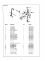
CRAFTSMAN
2000 PSI HIGH PRESSURE
WASHER
580.762010
FLATHEAD PUMP
BALL SEAT A$SEHBLY
P/N
B2152
VENTURI ASSEMBLY
P/N
_2151
SPACER
PLATE
ASSEMBLY
PIN
B2015
P/N
INLET
CHECK
VALVE
ASSEMBLY
P/N B3100
UNLOADER
P/N
SPINDLE
PUMP
P/N
ASSEMBLY
P/N
B2091
30
LINE
B1879
CHECK
A2034
HEAD
B2014
PRESSURE
VALVE
ASSEMBLY
CHECK
ASSEHBLY
VALVE
CRAFTSMAN
2000 PSI HIGH PRESSURE
WASHER
580.762010
FLAT HEAD PUMP
ITEM PART NO. QTY
1
2
3
93871
£6430A
96542
1
1
1
4
5
6
7
8
9
10
11
97675
97570
95524
£2479
95531
95435
97671V
97606
1
1
1
4
4
1
1
1
12
93790
1
13
14
15
16
17
18
19
20
21
22
23
97568A
96400
99427
94944
99735
93680
93666
93667
93652
95416
93876
1
3
3
3
1
3
3
3
1
1
1
24
25
26
27
28
29
30
31
A1320
93873
40945
A2069
A2062
A2060
97931
B2640
1
6
6
1
3
6
3
6
32
33
34
35
97929
97843
A2017
A1719
6
1
2
1
DESCRIPTION
ITEM
PART NO.
QTY
DESCRIPTION
36
37
38
A! 711
93656
A3829
1
1
1
SPINDLE Pressure Regulator
=O"RING, Spindle 1/4 x 3/8 x 1/16 cs
"(:7RING, Retainer Nut 14 x 17.56 x
1.78
39
40
41
42
43
44
A1712
A1716
A2016
A2.039
A2013
97840
1
1
NUT, Retainer- Spindle
SPRING, UNeader
1
1
PAR-BACK, Backup Ring
HANDLE, Unloader
6
3
BOLT, Head M8 x 1.25x 70ram Lg
"O" RING, Chk Valve Cap15.6 x 19.16 x
1.78
45
46
47
97841
20002
A3805
3
3
CAP, Outer Port
CAGE, Check Valve Ou_et
1
=O" RING, Venturi 10.82 x 14.38 x
1.78
48
49
50
51
52
53
54
55
56
57
58
59
60
61
62
63
64
65
66
67
68
69
73
74
A2217
A1318
B1758
96053
96015
A1717
B1757
A1718
93644
95380
95379
A1575
97855
A1713
A2015
A2503
A2756
891 38
21123
A1714
B2236
B2241
B2665
95441
3
1
1
SEAT, Check Valve OuSt
CYLINDER, Head
PLUG, Button M8 x 1.25 x 8mm
3
3
1
4
1
1
SEAL, H_h Pressure
RING, Bearing
MAGNET, Ball Deflector
R_UG,Button M6 x 1.0x 8mm
SET SCREW, M8 - 1.25 x 8 mm
ACTUATOR, Thermal Relief
1
1
1
1
1
1
SPRING, Chemical Irfjector
BALL, 5.5 dia. Chemical Injector
BARB HOSE, Brass with Nylon Insert
"C_'RING, Ball Seat 6.5 x 10.5 x 2 cs
SEAT, Ball Unloader
BALL, Stainless Steel 9/32 Dia.
1
1
SEAT, Trapped Une Pressure
VALVE, Shuttle Piston
1
1
SPRING, Check Valve
"O" RING, 3.68 x 7.24 x 1.78 cs
1
1
1
6
VENTURI, Chemical
LOCKNUT, M6 x 1.0 Nylon
CAP, Plastic
WASHER
1
PILOT, Engine
GASKET,_
Adapter
ADAPTER,Engine
BEARING,Eng.Adptr. RollerThrust
4x4
C - RING,Cam Retainer
WASHER,Thrust
WASHER,Retainer
LOCKWASHER,M8 Rbbed
BOLT,SHC5/16- 24 x 3/4" Lg
ADAPTER,EngineShaft3/4"
CAM,A.,dal6.0 Lilt
BEARING,AxialCam RollerThrust
5.5x 4
"(::7RING,Crankcase 113.97x119.21x
2.62
CRANKCASE P_np
SPRING,PistonRe_um
ASSEMBLY,CeramicFLu'on
& Cap
SHOE PistonPivot
ASSEMBLY,Breather
SEAL Oil Pk;ton
SPACER,Riot
SEAL,U - Cup ELF
SPRING,ThermalReliefActuator
PISTON,ThermalReliefActuator
"O"RING,ThermalRelief2.9x 6.5x
1.78
SPACER,InletRate
LOCKWASHER,M6 Rbbed
SCRE'W,SHC M6x 1.0x 20 mm Lg
GASKET,Head
SEAT,CheckValve Inlet
POPPET,CheckVak,e
CAGE CheckValveInlet
_C_RING,Chk Valve12.4x 1&96 x
1.78
SPRING,CheckValveOutlet
_3"RING,9.25x 12.81x 1.78
PAR-BACK,BackupRing
PIN,2.0 Dia.Spindle
31
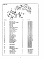
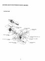
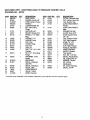
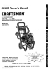
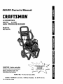
EXPLODED VIEW - CRAFTSMAN
DRAWING NO. - B2793
2000 PSI PRESSURE
WASHER
1054-0
17
15
t4
_49
44
5'
45
32
_
39
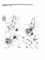
EXPLODED
VIEW ° CRAFTSMAN
DRAWING
NO. - B2793
ITEM
1
2
3
4
5
6
PARTNO.
EB2789
B2393
A 1803C*
EB2534
22129
52858
QTY.
1
1
1
1
8
2
7
8
9
51731
27007
B2142
2
2
2
10
11
12
13
14
15
16
75402
B2168
B1480
B1T/9
B2347
46476
31669
2
1
3
2
2
2
1
17
B2071
2
18
92235
19
20
B1631A
B1851
21
22
23
24
25
B2796
91373
79552
96307
A1040A
1
1
1
1
1
2000 PSI PRESSURE
DESCRIPTION
BASE, HSPW
ENGINE, Honda 5HP
PUMP, Me, urn Frame
HANDLE
LOCKWASHER, M8
NUT, M8 Locldng
Range
HHCS, M8x50
MOUNT, Rubber Foot
WHEEL, 2" x 9" Black
Mag
PUSHNUT, 1/2"
HANGER, Hose
CAP, Vinyl
COVER, Hinge
CAP, End
CAPLUG
BOLT, 1/4" - 20 x 1-3/4"
Carriage
NUT, 1/4" - 20 Locking
Range
GROMMET, Turbo
Nozzle
BILLBOARD
DECAL, Craftsman
2000 PSI
DECAL, Instructions
DECAL, Data
OVERLAMINATE
WASHER
1054-0
ITEM
26
27
29
30
PART NO.
A1041
A1408
B1288
21782
QTY.
1
1
1
1
DESORIFrlON
FILTER, Chemical Hose
CAP, Garden Hose Inlet
TAG, Breather Cap
QUICK DISCONNECT,
Female
QUICK DISCONNECT,
Male
31
21781
1
32
33
34
50190
48031G
B2759
2
1
1
WASHER, M8 Flat
CLAMP, Hose 3/16"
HOOK, Square Neck
1/4"-29
35
36
37
38
39
4O
41
43
44
45
46
47
46
49
97054
97100
B1969
95529
B2370
95587E
97123
21217
97566
45771
B2517
96382
B1849
B2730
1
1
1
1
1
1
1
4
1
8
1
1
1
1
TAG, Pressure Adjust
CAP, High Pressure
HOSE, 1/4" x 25'
TURBO, Nozzle
GUN, High Pressure
NOZZLE, Adjustable
WAND, Extension
MOUNT, VibraSon
TAG, Nozzle
NUT, M8 - 1.25 Hex
DECAL, Recoil Honda
OIL, Engine SAE 30
MANUAL, Owners
KIT, O-Ring
Maintenance
50
51
97009
B3095
1
1
KIT, Nozzle Cleaning
DECAL, 5.0 HP
DECAL, 1-800 #
HOSE, Chemical
* Complete pump assembly is not available. Reference pump exploded view for individual parts.
33
For the repair or replacement parts you
need delivered directly to your home
Call 7 a.m. - 7 p.m., 7 days a week
1-800-366-PART
(1-800-366-7278)
For in-home major
brand repair service
Call 24 hours a day, 7 days a week
1-800-4-REPAIR
(1-800-473-7247)
For the location of a Sears Parts and
Repair Center in your area
Call 24 hours a day, 7 days a week
1-800-488-1222
For information on purchasing a Sears
Maintenance Agreement or to inquire
about an existing agreement
Call 9 a.m. - 5 p.m., Monday-Saturday
1-800-827-6655
The model number of your product is on a
decal attached to the pressure washer.
The model number of the engine is located
on the blower housing of the engine.
When requesting service or ordering parts,
always provide the following information:
• Product Type
• Model Number
• Part Number
• Part Description
34
America's
Repair Specialists