1
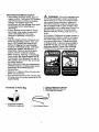
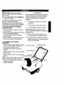
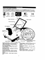
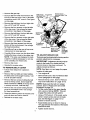
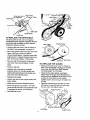
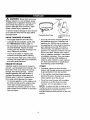
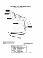
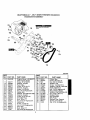
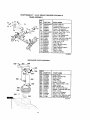
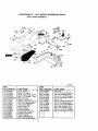
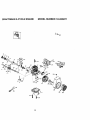
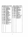
5.0 Horsepower
21 Inch Single Stage
Auger Propelled
SNOW THROWER
Electric Start
MODEL NO.
536.885210
Caution:
Read and follow all Safety
Rules and Operating
Instructions before first use
of this product,
SEARS, ROEBUCK AND CO., Hoffman Estates, IL 60179 U.S.A.
761893 07/27/98
Table of Contents
Warranty
Safety Rules.
Contents of Shipping Carton
Assembly
Operation
Maintenance
LIMITED TWO-YEAR
2
2
2-4
4
5
6-10
f1
WARRANTY
Service and Adjustments
Storage
Troubleshooting
Snow Repair Parts '
Engine Repair Parts
Spanish(Espa=5ol)
Parts Ordering/Service
ON CRAFTSMAN
12-15
16
17
18-24
25-29
30-46
Back Cover
SNOW THROWER
For two years from the date of purchase, when this Craftsman Snow Thrower is maintained, lubricated, and tuned up according to the operating and maintenance instructions in the owner's manual, Craftsman will repair, free of charge, any defect in material or workmanship.
If this Craftsman Snow Thrower is used for commercial or rental purposes, this warranty applies for only 90 days from the date of purchase.
This warranty does not cover the following:
• Items which become worn during normal use, such as spark plugs, drive belts and
shear pins.
• Repairs necessary because of operator abuse or negligence, including bent crank
shafts and the failure to maintain the equipment according to the instructions contained in the owner's manual.
WARRANTY SERVICE IS AVAILABLE BY RETURNING THE CRAFTSMAN SNOW
THROWER TO THE NEAREST CRAFTSMAN SERVICE CENTER/DEPARTMENT
IN
THE UNITED STATES. THIS WARRANTY APPLIES ONLY WHILE THIS PRODUCT
IS IN USE IN THE UNITED STATES.
This warranty gives you specific legal rights, and you may also have other rights which
may vary from state to state.
Sears, Roebuck and Co., D817WA, Hoffman Estates, IL 60179
,,,k
Look for this symbol to point out important safety precautions.
ATTENTION!!!
Become alertJI Your safety is involved.
N
CAUTION: Always turn key to OFF
position and remove key to prevent
accidental starting when setting-up,
transporting, adjusting or making repairs.
IMPORTANT: Safety standards require
operator presence controls to minimize the
risk of injury. Your snow thrower is
equipped with such controls. Do not attempt
to defeat the function of the operator
_resence control under any circumstances,
_
California
Proposition 65
WARNING:
The
engine exhaust from this product
contains
chemicals
known
to the
State of California to cause cancer
birth defects or other reproductive
harm.
It means--
BEFORE USE
• Read the owner's manual carefully. Be
thoroughly familiar with the controls and
the proper use of the snow thrower. Know
how to stop the snow thrower and
disengage the controls quickly.
• Do not operate the snow thrower without
wearing adequate outer garments. Wear
footwear that will improve footing on
slippery surfaces.
• Keep the area of operation clear of all
persons, particularly small children and
pets.
• Thoroughly inspect the area where the
snow thrower is to be used and remove
all foreign objects.
• Use extension cords and receptacles as
specified by the manufacturer for all snow
throwers with electric drive motors or with
factory-installed
or optional starting
motors.
• Use only attachments and accessories
approved by the manufacturer of the
snow thrower (such as e|ectric starter kits,
etc.).
• Never operate the Snow thrower without
good visibility or light. Always be sure of
your footing, and keep a firm hold on the
handles. Walk; never run.
• This snow thrower is for use on sidewalks, driveways, and other ground level
surfaces. CAUTION: should be exercised
while using on steep sloping surfaces. DO
NOT USE SNOW THROWER ON
SURFACES ABOVE GROUND LEVEL
such as roofs of residences, garages,
porches or other such structures or
buildings.
• Check all bolts at frequent intervals for
proper tightness to be sure the snow
thrower is in safe working condition.
• Disengage clutch before starting the
engine.
• Let engine and snow thrower adjust to
outdoor temperatures before starting to
clear snow.
FUEL SAFETY
• Handle fuel with care; it is highly flammable.
• Use an approved container.
• Check fuel supply before each use,
allowing space for expansion as the heat
of the engine and/or sun can cause fuel to
expand.
• Fill fuel tank outdoors with extreme care.
Never fill fuel tank indoors. Replace fuel
tank cap securely and wipe up spilled
fuel.
• Never remove the fuel tank cap or add
fuel to a running or hot engine.
• Never store fuel or snow thrower with fuel
in the tank inside a building where fumes
may reach an open flame.
OPERATING SAFETY
• Never allow children or young teenagers
to operate the snow thrower. Keep them
away while it is operating. Never allow
adults to operate the snow thrower
without proper instruction.
• Do not operate this machine if you are
taking drugs or other medication which
can cause drowsiness or affect your
ability to operate this machine.
• Do not use this machine if you are
mentally or physically unable to operate
this machine safely.
• Always wear safety glasses or eye
shields during operation or while perform-
•
•
•
•
•
•
•
•
ing an adjustment or repair to protect
eyes from foreign objects that may be
thrown from the snow thrower.
Do not put hands or feet near or under
rotating parts. Keep clear of the discharge
opening at all times.
Exercise extreme caution to avoid
or falling, especially when operating in
reverse or backing up.
Do not clear snow across the face of
slopes. Excercise caultion when changing
direction on slopes..Do not attempt to
clear steep slopes.
Never operate the snow thrower without
proper guards, plates, or other safety
protective devices in place.
Never operate the snow thrower near
glass enclosures, automobiles, window
wells, drop-offs, and the like without
proper adjustment of the snow discharge
angle. Keep children and pets away.
Never operate the snow thrower at high
transport speeds on slippery surfaces.
Look behind and use care when backing.
Never direct discharge at bystanders or
allow anyone in front of the snow thrower.
Do not run the engine indoors, except
when starting the engine and for transporting the snow thrower in or out of the
building. Open the outside doors; exhaust
fumes are dangerous, containing CARBON MONOXIDE, an ODORLESS and
DEADLY GAS.
• Take all possible precautions when
leaving the snow thrower unattended.
Disengage the auger/impeller, stop
engine, and remove key.
• Do not overload the machine capacity by
attempting to clear snow at too fast a rate.
SAFE STORAGE
• Always refer to the owner's manual
instructions for important details if the
snow thrower is to be stored for an
extended period.
• Disengage power to the auger/impeller
when snow thrower is transported or not
in use.
• Never store the snow thrower with fuel in
the fuel tank inside a building where
ignition sources are present such as water
and space heaters, clothes dryers, and
the like. Allow the engine to cool before
storing in any enclosure.
REPAIR/ADJUSTMENTS
SAFETY
• Afterstrikinga foreignobject,stopthe
engine (motor). Turn key to OFF position
and remove key to prevent accidental
starting. Thoroughly inspect the
snowthrower for any damage, and repair
the damage before restarting and
operating it.
• If snow thrower should start to vibrate
abnormally, stop engine (motor) and
check immediately for the cause.
Vibration is generally a warning of
trouble.
• Stop the engine (motor) whenever you
leave the operating position. Also, turn
key to OFF position and remove key
before unclogging the auger/impeller
housing or discharge chute, and when
making any repairs, adjustments, or
inspections. Remove wire from spark
plug to prevent accidental starting.
• When cleaning, repairing, or inspecting,
make certain the auger/impeller and all
moving parts have stopped.Turn key to
OFF position and remove key to prevent
accidental starting.
• Never attempt to make any adjustments
while the engine is running except when
specifically recommended by the
manufacturer.
Z_
WARNING:
This unit is equipped with
an internal combustion engine and should
not be used on or near any unimproved forest-covered, brush-covered or grass-covered land unless the engine's exhaust system is equipped with a spark arrester meeting applicable local or state laws (if any). If a
spark arrester is used, it should be maintained in effective working order by the operator.
In the state of California the spark arrester is
required by law (Section 4442 of the California Public Resources Code). Other states
may have similar laws. Federal laws apply
on federal lands. A spark arresterimuffler is
available through your nearest Craftsman
Authorized Service Center (See ENGINE
REPAIR PARTS section in this manual).
• Maintain or replace safety and instruction
labels, as necessary.
• Run the snow thrower a few minutes after
throwing snow to prevent freeze-up of the
auger/impeller.
Contents of Parts Bag
1 - 3.2 ounce container
Craftsman 2-cycle oil
1 - Owner's Manual (not shown)
1 -Warranty Card (not shown)
1 - Parts Bag (not shown)
1 - 10 ft. Electric Cord
CAUTION" Always wear safety
glasses or eye shields while assembling
snow thrower.
TOOLS
REQUIRED
FOR ASSEMBLY
1 - Knife to cut carton
The figure to the right shows the snow
thrower completely assembled.
CHECKLIST
Before you operate your new snow thrower,
to ensure that you receive the best performance and satisfaction from this quality
product, please review the following
checklist:
_/
All assembly instructions have been
References to the right or left hand side
of the snow thrower are from the viewpoint
of the operator's position behind the unit.
The discharge chute rotates freely.
TO REMOVE
SNOW
FROM CARTON
No remaining
completed.
THROWER
loose parts in carton.
• Locate and remove container of Crafts-
While learning how to use your snow
man 2-cycle oil.
• Remove the inserts positioned around the
unit and the packing material.
• Cut down all four corners and lay the
panel down flat.
thrower, pay extra attention to the following
important items:
• Remove and discard bottom packaging.
• Pull snow thrower out of the carton.
_/_/ Become familiar with all controls-their
TO ASSEMBLE
THROWER
THE
_/_/ Make sure gas tank is filled with the
40:1 ratio mixture of gasoline and oil.
location and function. Operate controls
before starting engine.
SNOW
• Remove wrap on upper handle and along
the side of both handles.Discard wrap.
Operatin
Au
• Unfold upper handle to remove
packaging on the control panel and
discard.
• Loosen the tee knobs on each side of the
upper handle.
Chute Control Rod
\
• Raise the upper handle to the operating
Tee Knob
Chute Deflector
position.
NOTE: Make sure the cable is not caught
between the upper and lower handle.
• Check to be sure the clutch cable is not
caught in the handle.
• Tighten tee knobs.
i Position
KNOW YOUR SNOW THROWER
READ THIS OWNER'S MANUAL AND SAFETY RULES BEFORE OPERATING YOUR
SNOW THROWER. Compare the illustrations with your SNOW THROWER
to familiarize
yourself with the location of various controls and adjustments. Save this manual for future
reference.
Etecric
Ignition Off
Ignition On
Start
Oil/Fuel Mixture
Primer Button
Spark Plug
Auger Control
Chute Control
Lower Handle
Chute Deflector
Discharge.,
Chute
AugG
Choke
!lectric Starter
Button
Auger Housing
Auger Control Bar - Starts and stops the
auger which propels the snow thrower.
Chute Control Rod - Changes the direction of snow discharge.
Chute Deflector - Changes the distance
the snow is thrown.
Discharge Chute - Changes the direction
the snow is thrown.
Ignition Switch Key - Must be inserted
and turned to the ON position to start the
engine.
Choke Control - Used to start a cold engine.
Primer Button - Injects fuel directly into the
carburetor manifold for fast starts in cold
weather,
Recoil Starter Handle - Starts the engine
manually. ,
Spark Plug Access Panel - Aides in spark
plug removal.
Electric Starter Button - Used to start the
engine using the 120V electric starter.
A
HOW
SNOW
TO USE YOUR
THROWER
TO STOP
YOUR
SNOW
THROWER
• To stop the auger, release the auger
control bar.
NOTE: If the auger continues to creep, refer
(To Adjust Auger Control Cable paragraph on
page 11).
• To stop the engine, turn key to the OFF
position.
TO CONTROL
SNOW
DISCHARGE
• Turn the chute control rod to set the
direction of the snow throwing.
• Loosen the tee knob on the chute
deflector and move the deflector to set
the distance. Move the deflector (UP) for
more distance, (DOWN) for less distance.
Then tighten the tee knob (See figure
below).
Tee Knob
Z_
CAUTION:
Read owner's manual
before operating machine. Never direct
discharge toward bystanders. Release the
auger control bar and stop the engine
before unclogging discharge chute or auger
housing and before leaving the machine.
BEFORE
WARNING:
STARTING
Experience
ENGINE
indicates
that
alcohol blended fuels (called gasohol or
those using ethanol or methanol) can
attract moisture whic h leads to separation
and formation of acids during storage.
Acidic gas can damage the fuel system of
an engine while in storage. To avoid engine
problems, the fuel system should be
emptied before storage for 30 days or
longer. Start engine and let it run until fuel
lines and carburetor are empty. Use
carburetor bowl drain to empty residual
gasoline from float chamber (See figure in
Storage section, page 16). Use fresh fuel
next season. (See Storage Instructions on
page 16 for additional information).
Never use engine or carburetor cleaner
products in the fuel tank or permanent
damage may occur.
FILL GAS
TO USE AUGER
PROPEL ACTION
• Squeeze the auger control bar down
against the upper handle to allow the
auger to turn.
• To propel forward, raise the handle to
allow the rubber auger blades to contact
the ground (See figure below).
Normal
Auger Propelled
Operating
Position
Position
NOTICE: ENGINES WHICH ARE CERTIFIED TO COMPLY WITH CALIFORNIA
AND US EPA EMISSION REGULATIONS
FOR ULGE ENGINES: Are certified to
operate on regular unleaded gasoline.
Include the following emisssion control
system(s): EM, TWC (if so equipped).
Include any user adjustable features therefore no other adustments are
needed.The two cycle engine used on this
snow thrower requires a mixture of gasoline
and oil for lubrication of the bearings and
other moving parts. The correct fuel mixture
ratio is 40:1 (3.2 oz. oil per gallon of gas see Fuel Mixture Chart). Gasoline and oil
must be pre-mixed in a clean gasoline
container. Always use fresh, clean, unleaded gasoline.
FUEL MIX CHART (Mixture 40:1)
l u. s.
I IMPERZAL
s.I. (METRIC)
I
o,sro,,p,sro,,. o,si o,,i
Rubber Auger
Blades
' °a't °'t"°°"l3.,o..
,,,r. too,,,,.
I
DO NOT FILL THE FUEL TANK WITH GASOLINE
THAT DOES NOT HAVE OIL MIXED IN IT.
THE FUEL TANK.
OII
(1/2 cup or 3.2 oz.)
Shake Can
1 U,S. gallon container
GASOLINE
TO STOP
AND OIL MIXTURE
• To stop the engine, turn the key to OFF
and remove key. Keep key in a safe
place. The engine will not start without the
key. See figure on next page.
Mix gasoline and oil as follows:
• Pour I U.S. quart of fresh, clean,
unleaded automotive gasoline to a gallon
gasoline container.
• Add 3.2 oz of clean, high quality, Craftsman two-cycle oil into the gasoline
container (One 3.2 ounces of oil provided).
TO START
START)
ENGINE
(ELECTRIC
The snow thrower engine is equipped with a
120 volt AC electric starter and recoil starter.
IMPORTANT:
Do not use outboard motor
oil or automobile oils, such as SAE 30 oil,
or multi-viscosity
10W-40.
ENGINE
Before starting the engine, be certain that
you have read the following information:
oils, such as 10W-30 or
COLD START
• Reinstall the cap on the gasoline container and shake container vigorously so
the oil mixes with the gasoline
• Insert the key and turn ON.
• Add an additional 3 U.S. quarts of
gasoline to the gallon container and
shake the container again.
WARNING:
Gasoline is flammable and
• Connect the power cord to the switch box
on the snow thrower.
• Move the choke control to the FULL
position.
• Plug the other end of the power cord into
a three hole, grounded 120 volt AC
receptacle.
caution must be used when handling or
storing it. Do not fill fuel tank while snow
thrower is running, hot, or when snow
thrower is in an enclosed area. Keep away
from open flame, electrical spark, and do
not smoke while filling the fuel tank. Never
fill fuel tank completely; but fill the tank to
within 1/4-1/2 inch from the top to provide
space for expansion of fuel. Always fill fuel
tank outdoors and use a funnel or spout to
prevent spilling. Make sure to wipe up any
spilled fuel before starting the engine. Store
gasoline in a clean, approved container, and
keep the cap in place on the container.
Keep gasoline in a cool, well ventilated
place; never in the house. Never buy more
than a 30 day supply of gasoline to ensure
volatility. Gasoline is intended to be used as
a fuel for internal combustion engines;
therefore, do not use gasoline for any other
purpose. Since many children like the smell
of gasoline, keep it out of their reach
because the fumes are dangerous to inhale,
as well as being explosive.
• Push the primer button while covering the
vent holes as follows: (Remove finger
from primer button between primes).
Do not prime if temperature is above
50°F.
Two times if temperature is 50 ° F to 15°F.
Four times if temperature is below 15°F.
• Push down on the starter button until the
engine starts. Do not crank for more than
10 seconBs at a time. This electric starter
is thermally protected. If overheated it will
stop automatically and can be restarted
only when it has cooled to a safe temperature (a wait of about 5 to 10 minutes is
required.
• Disconnect the power cord from the
receptacle first and then from the switch
box on the snow thrower.
8
•
As engine warms up and begins to
operate evenly, move the choke control
slowly to the OFF position. If the engine
falters, turn to 1/2 choke until it runs
smoothly,
then move to OFF
position.
• Move the choke control to the FULL
position.
• Push the primer button while covering the
vent holes as follows: (Remove finger
from primer button between primes).
NOTE: Allow the engine.to warm up for a
few minutes before using snow thrower, as
the engine will not develop full power until it
reaches operating temperature.
WARM
START
• Be sure the choke is in the OFF position and pull the starter handle until the
engine starts.
• Do not prime a warm engine. If the engine fails to start, follow the Cold Engine Start instructions on page 8.
Recoil Starter
Primer Button Handle
o
Electric Start
Switch Box
Button
This starter is equipped to
operate on 120 volt AC household
current.
Follow all instructions carefully as set forth
in the "To Start Engine" section. When
connecting 120 volt AC power cord, always
connect the cord to the switch box on the
engine first, then plug the other end into the
household receptacle. When disconnecting
the 120 volt AC power cord, always unplug
from the household receptacle first.
TO STOP ENGINE
• To stop the engine, turn the key to OFF
and remove key. Keep key in a safe
place. The engine will not start without the
key. See figure above.
TO START
ENGINE
Two times if temperature
is 50 ° F to 15°F.
Four times if temperature
is below 15°F.
• Pull the starter handle with a smooth rapid
movement. Do not allow the starter rope
to snap back. Rewind smoothly while
holding the starter handle. If the engine
fires but does not start, pull the starter
handle until the engine starts.
• Afterthree pulls, repeat the priming and
pulling steps again.
• As engine starts warms up move choke
lever to "1/2 choke" position. When
engine runs smoothly, move choke lever
to "No Choke" Position
o
CAUTION:
is above 50°F.
NOTE: Allow the engine to warm up for
several minutes before blowing snow in
temperatures below 0°F.
WARM START
Choke Control
Z_
One time if temperature
(RECOIL
START)
Before starting the engine, be certain that
you have read and understood all the
instructions on the preceding
COLD START
• Insert the key and turn ON.
pages.
• Be sure the choke is in the OFF position and pull the starter handle until the
engine starts.
• Do not prime a warm engine. If the engine fails to start, follow the Cold Engine Start instructions on page 8.
/_
CAUTION:
Never run engine indoors
or in enclosed, poody ventilated areas.
Engine exhaust contains carbon monoxide,
an odorless and a deadly gas. Always stand
behind snow thrower(operator's position)
when starting engine. Do not put hands,
feet, hair or loose clothing in or near the
discharge chute deflector or auger housing
while the engine is running. The temperature of the muffler and neaby areas may
exceed 150 ° _; avoid these areas also.
,&
LL_ WARNING:
Objects such as gravel,
rocks or other debris, if struck by the auger,
may be thrown with sufficient force to cause
personal injury or property damage.
We recommend standard safety glasses or
Wide Vision Safety Mask for over your
glasses.
SNOW
THROWING
WET PACKED SNOW
TIPS
• This snow thrower will propel itself
forward when the handle is raised
Move slowly into snow of this condition.
The greater the depth, the slower you
should go. When it appears that the wet,
packed snow is causing the auger to slow
down and the chute to clog, back off and
begin a series of short jabs into the snow.
These short back and forth, 4 to 6 inch,
jabbing motions will "belch" the snow
from the chute.
enough to cause the auger blades to
contact the ground. The auger should
stop when auger control bar is released,
If it does not, refer to Adjust Auger
Control Cable paragraph on page 12.
• For most efficient snow throwing, turn the
discharge chute deflector to throw snow
downwind, and slightly overlap each
swath. In light snow take up to a full cut
and in heavy snow take less than a full
cut.
SNOW
BANKS
DRIFTS
• In snow of greater depth than the unit,
use the jabbing technique described
above. Turn the discharge chute away
from the snow bank. More time will be
• The distance snow will be discharged can
be adjusted by moving the discharge
chute deflector. Raise the deflector for
more distance or lower the deflector for
less distance.
required to remove snow of this type than
level snow.
PRODUCT SPECIFICATIONS
HORSE POWER:
5HP
• In windy conditions, Iower the chute
deflector to direct discharged snow close
to the ground where it is less likely to
blow into unwanted areas.
DISPLACEMENT:
• Keep the area to be cleared free of
8.46 cu. in.
GASOLINE CAPACITY:
stones, toys and other foreign objects for
safety and to prevent damage to the
snow thrower.
1.62 quart
(unleaded)
FUEL/OIL MtX RATIO: 40:!
(3.2 oz. of aircooled engine 2
cycle oil specified
for 40:1 per 1 gal. of
gas)
• Do not use the auger propelling feature
when clearing gravel or crushed rock
driveways. Move the handle down to
raise the auger slightly.
SPARKPLUG:
• The allowable forward speed of the snow
thrower is dependent on the depth and
weight of the snow. Experience will
establish the most effective method of
using the snow thrower under different
conditions.
DRY AND AVERAGE
AND
SNOW
• Snow up to eight inch depth can be
removed rapidly and easily by walking at
a moderate rate. For snow or drifts of a
greater depth you may find it desirable to
slow your pace to allow the discharge
chute to dispose of the snow as rapidly
as the auger receives the snow.
• Plan to have the snow discharged in the
direction the wind is blowing.
10
Champion RCJ8Y
(Gap .030) or
Equivalent
CUSTOMER
RESPONSIBILITIES
SCHEDULE
SERVICE
RECORDS
Fill in dates as
you complete
regular service
Before
Each
Use
After
first 12
Hours
AS
Needed
Before
Storage
SERVICE
DATES
Begin
Each
Season
Tighten All Screws & Nuts
Check Spark Plug
v,'
Check Drive Belts
Lubricate Chute Control Flange
Check Fuel
v"
Drain Fuel
GENERAL
• Make sure that the spark plug is tightened securely into the engine and the
spark plug wire is attached to the spark
plug.
RECOMMENDATIONS
The warranty on this snow thrower does not
cover items that have been subjected to operator abuse or negligence. To receive full
value from the warranty, the operator must
maintain the snow thrower as instructed in
this manual. The above chart is provided to
assist the operator in properly maintaining
the snow thrower.
SNOW
AFTER
• If a torque wrench is available, torque
plug to 18 to 23 foot pounds.
• Clean the area around the spark plug
base before removal to prevent dirt from
entering the engine.
THROWER
FIRST
LUBRICATION
USE
CHART
• Check for any loose or damaged parts
after each use.
• Tighten any loose fasteners.
AFTER
EACH
USE
• Run the machine to clear the auger of
snow.
• Remove all snow and slush from the snow
thrower to prevent freezing of auger or
controls.
LUBRICATION
- AS REQUIRED
• Lubricate the flange on the discharge
chute before storage. See To Remove
Top Cover instructions on page 12.
• See Lubrication Chart diagram for
lubrication points and type of lubricant.
ENGINE
SPARK
Lubricate chutecontrolflange,
Coat flangewitha clingingtype
grease such as Lubdplate.
PLUG
• Clean the spark plug and reset the gap
periodically. To service or replace spark
plug. See To Replace the Spark Plug
paragraph on page 15.
11
CARBURETOR
• Remove the "Z" hook from the top hole in
the cable adjustment bracket and move to
the next hole away from the top of the
bracket. See second figure.
ADJUSTMENT
The carburetor on this snow thrower is not
adjustable.
IMPORTANT:
If you think the carburetor is
not operating properly, contact your
nearest Craftsman service center.
_
CAUTION:
• Pull cable slack through cable adjustment
bracket and insert in the control bar. See
third figure.
Never tamper with the
• Replace boot o_/er cable adjustment
bracket.
engine governor which is factory set for
proper engine speed. Over speeding the
engine may increase the danger of
personal injury and will void the engine
warranty. If you think the engine governor
high speed needs adjusting, contact your
nearest Craftsman service center who
has the proper equipment and experience
to make any unnecessary adjustments.
TO ADJUST
ASSEMBLY
• Insert "Z" hook in the auger control bar.
See second figure.
• Start the snow thrower and check that the
auger does not continue to turn when the
auger control bar is released.
Adjustments
THE CHUTE CRANK
Notch in
Flange
ustment Bracket
If you cannot rotate the chute crank fully to the
left and to the right, you need to adjust the
chute crank. See first figure on this page.
orm
• Remove the top cover. See To Remove
Top Cover instructions on this page.
• Loosen both 1/2" nuts on the crank
adjusting bracket using 1/2" wrenches.
Auger Control
Bar
• Swivel the crank adjusting bracket to
allow about 1/8" clearance between the
notch in the flange and the outer diameter
of the worm.
• Once this clearance is set, tighten the
nuts.
Hook
TO ADJUSTTHEAUGERCONTROL
CABLE
The auger control cable is set at the factory for
proper operation. If you need to adjust the
cable, because the control bar does not properly engage or disengage the auger, do the
following:
Cable--_
• Remove "Z" hook from the auger control
bar. See second figure.
_
• Slide the boot toward the loose end of the
F,_'
Cable Adjust- ._/j
ment Brlcket!/
_"Z"
Hook
Cm_b,_
A dJcUkSet
i
_i_o_o_Jm=;_Bracke t
cable. See third figure.
TO REMOVE
• Push the cable down through the hole in
the top of the cable adjustment bracket to
provide slack in the cable. See third figure
TOP
COVER
• Follow these steps from operator's
position.
• Remove the T-knob and fasteners on the
discharge chute.
12
• Remove the gas cap.
Screws to be
removed from Top
Boltsto be
removedfrom
T,
• Remove the two bolts and nuts from the
front lip of the top cover. Use a flat head
screwdriver and a 3/8" wrench. See figure
c,n this page.
• Remove the Idolt from the front right side.
Use a 5/16" and 3/8" wrench.
• Remove the four screws on the left side
of the top cover. Use a large flat head
screwdriver. See figure on this page.
Cover
• Remove the bolt from the front left side.
Use a 5/16" and 3/8" wrench.
Chute
• Remove the four screws on the right side
of the top cover. Use a large flat head
screwdriver.
See figure on this page.
• Remove the three screws from the top
portion of the control panel. Use a large
flat head screwdriver.
Fasteners
Lower Chute
tobe
• Carefully pull up on the rear of top cover
making sure to clear gas tank.
• Carefully
removed from
Belt Cover
lift top cover over the three bolts
TO ADJUST
holding the lower chute to the chute ring.
NOTE: This area was designed to have
a tight fit, it will be necessary to rock top
cover carefully over these bolts.
PAD
IMPORTANT:
Adjustment should only be
made to the brake if the brake pad has
become loose or has been removed. To
adjust proceed as follows:
in reverse order.
TO REMOVE
fromBelt
Cover
The brake pad isadjusted at the factory and no
periodic adjustment is necessary.
• Remove top cover.
• Reinstall
BRAKE
removed
BELT COVER
• Follow these steps from operator's
position.
NOTE: See figure on next page for proper
• Remove the four bolts and nuts holding
the belt cover to the auger housing. Use
a 5/16" and 3/8" wrench.
•Tum
• Remove the two screws holding the belt
cover to the top cover. Use a large flat
head screwdriver. NOTE: If the top cover
is already removed, omit this step.
• Remove the top cover. See To Remove
Top Cover instructions on page 12-13.
location of brake pad.
engine off.
• Remove belt cover. See To Remove Belt
Cover paragraph on this page.
NOTE: Make sure the belt is in proper
position. See To Replace the Drive Belt
paragraph on page 14.
• Tie the control bail to the upper handle
with a piece of string. NOTE: This will
engage the pulley and belt system.
• Remove the one screw holding the belt
cover to the bottom cover. Use a large
flat head screwdriver.
• Grasp the bottom portion of the belt cover
and pull down and out to remove.
• Using a 7/16•wrench, 7/16 socket, and a
rachet loosen screw and nut on brake
• Reinstall in reverse order.
pad. See first figure on page 14 for
location of screw and nut.
• Adjust brake pad up or down to have a
1/8" gap between the bottom of the brake
pad and the belt.
• Tighten screw and nut.
13
Screw and nut to Idler Pulley
be loosened
Pulley
l
_"_
Brake Pad
Engine Pulley---_-_\_
Idler Pulley-_>_i.,_
Brake Pad.L_'_'_\//\
_Roller
TO REPLACE
THE
DRIVE
/
/
*_%_JJ_//_Jr
BELT
Roller
\Drive
Belt
The drive belt on this unit is of special
construction and must be replaced with the
same type belt available at your nearest
Craftsman Service Center.
• Remove the belt cover. See to Remove
the Belt Cover paragraph on page 13.
• Move belt guide away from belt. See next
figure. Belt may come out without
loosening belt guide. Carefully press idler
pulley down to release brake pressure on
belt. See second figure on this page.
• Remove belt from between brake pad
and relier. See second figure on this
TO REPLACE
page.
• Remove old belt.
THE
AUGER
• Remove the belt cover, see To Remove
Belt Cover paragraph on page 13 and the
drive belt. See the Drive Belt Replacement paragraph on this page.
• Replace with new belt by carefully
pressing down on the idler pulley and
placing the belt between the brake pad
and roller with belt ribs down.
• Remove the auger pulley, see figure
below from the auger shaft (threads are
left hand; turn clockwise to remove). Place
a piece of wood (2x4) on the center
paddle area to secure auger to keep from
turning.
• Remove the bearing assembly from the
left frame of snow thrower by removing
the two nuts. See figure below.
, Release belt pulley.
• Attach new belt to the engine pulley and
auger pulley.
• Make sure the belt is seated properly.
• Move belt guide into position. The belt
guide should be 3/32" from belt when belt
is engaged as shown in third figure.
• Reinstall belt cover.
Bearint;
Left F#ame
14
• Slide the auger assembly out of the
bearing assembly on the right side of the
snow thrower.
• Push the spark plug wire onto the spark
plug.
• Reinstall the bottom cover.
• Tip the auger assembly enough to allow it
to slide out of the auger housing.
ENGINE
• Install the new auger assembly in reverse
order of removal.
Unless the operator is fully qualified to
make engine repairs or adjustments, we
recommend that such work should be done
TO REPLACE
THE SPARK PLUG
NOTICE: This spark ignition system meets
all requirements of the Canadian Interference-Causing Equipment Regulations.
SERVICE
by technicians trained to work on snow
thrower type engines. Take your snow
thrower to your nearest Craftsman Service
Center for repair and adjustment.
NOTICE: This engine complies with all current Australian and New Zealand limitaions
regarding electromagnetic interference.
ADJUST
ENGINE
SPEED
Your engine speed has been factory set. Do
not attempt to change engine speed or it may
result in personal injury. If you believe that
the engine is running too fast or too slow, take
your snow thrower to your nearest Craftsman
Service Center for repair and adjustment.
The spark plug is underneath the control
panel and is accessible through the spark
plug access cover.
• Remove black plastic spark plug access
cover by squeezing the sides and pulling
cover away. See figure below.
• The spark plug and wire are now visible.
• Remove the spark plug wire.
• Clean the area around the plug base to
prevent dirt from entering the engine
when the plug is removed.
• Remove the spark plug. If it is cracked,
fouled or dirty, it must be replaced. See
page 10 for the proper replacement plug.
• Set the gap between the electrodes of the
new spark plug at .030 inch. Next, install
the spark plug in the cylinder head.
• Torque plug to 18 to 20 ft. lb. If you do not
use a torque wrench, tighten the plug
firmly.
15
Carburetor
Z_ WARNING:
Never store your snow
thrower indoors or in an enclosed, poorly
ventilated area. If gasoline remains in the
tank, fumes may reach an open flame,
spark or pilot light from a furnace, water
heater, clothes dryer, cigarette, etc.
To prevent engine damage (if snow thrower
is not used for more than 30 days) follow
the steps below.
SNOW
THROWER
Carbu
STORAGE
Right side view of
engine
I! you do not want to remove gasoline, a
fuel stabilizer (such as Craftsman fuel
stabilizer No. 33500) may be added to
• Thoroughly clean the snow thrower.
• Lubricate all the lubrication points. See
the Maintenance section, page 11.
any gasotine left in the tank to minimize
gum deposits and acids. If the tank is
almost empty, mix stabilizer with fresh
gasoline in a separate container and add
some to the tank. Always follow instructions on stabilizer container. Instructions
on stabilizer container. Then run engine
at least 10 minutes after stabilizer is
added to allow mixture to reach carburetor. Store snow thrower in a safe place.
• Be sure that all nuts, bolts and screws are
securely fastened. Inspect all visible
moving parts for damage, breakage and
wear. Replace if necessary.
• Touch up art rusted or chipped paint
surfaces; sand lightly before painting.
• Cover the bare metal parts of the blower
housing and auger with rust preventative,
such as a spray lubricant.
ENGINE
Drain
See Warning under STORAGE.
STORAGE
Gasoline must be removed or treated to
OTHER
prevent gum deposits from forming in the
tank, filter, hose, and carburetor during
storage. Also during storage, alcohol
blended gasoline that uses ethanol or
methanol (sometimes called gasohel)
attracts water, it acts on the gasoline to
• If possible, store your snow thrower
indoors with the gas removed and cover it
to give protection from dust and dirt.
form acids which damage the engine.
• To remove gasoline, run the engine until
the tank is empty and the engine stops.
Then drain remaining gasoline from
carburetor by pressing upward on bowl
drain located on the bottom of carburetor.
• Cover the snow thrower with a suitable
• If the machine must be stored outdoors,
block up the snow thrower to be sure the
entire machine is off the ground.
protective cover that does not retain
moisture. Do not use plastic or vinyl.
NOTE:
A yearly checkup or tune-up at a
Craftsman Service Center is a good way of
ensuring that your snow thrower wilt
provide maximum performance for the next
season.
See next figure.
16
TROUBLE
CAUSE
CORRECTION
Difficult starting
Defective spark plug
Replace defectiv3 plug
Engine stalls
Unit running on CHOKE
Move choke lever to OFF positor
Blocked fuel line or low on fuel
Clean fuel line; check fuel supply; add fresh gasoline (gasoline/oil mixture if 2-cycle engine)
Use carburetor bowl drain to
flush and refill with fresh fuel
Engine runs
erractically
or
Water or dirt in fuel system
Loss of power
Excessive
vibration
Loose parts; damaged
Damaged
Units fails to
propel itself
auger
Stop engine immediately and
turn key to OFF position and remove key. Tighten all bolts and
make all necessary repairs. If vibration continues, have the unit
serviced by a Craftsman service
repairman
Repair or replace auger assembly
Drive belt loose or damaged
Incorrect adjustment
trol cable
Unit fails to
discharge snow
impeller
of auger con-
Auger drive belt loose or damaged
Replace drive belt
Adjust auger control cable
Replace if damaged
Adjust auger control cable
Auger control cable not adjusted
correctly
Discharge
chute clogged
Foreign object lodged in auger
17
Stop engine immediately and turr
key to OFF position and remove
key. Clean discharge chute and
inside of auger housing
Stop engine immediately and turr
key to OFF position and remove
key. Remove object from auger.
CRAFTSMAN
21" - 5H.P. SNOW THROWER
536.885210
ELECTRIC START ASSEMBLY
Nots: Always use original equipment
parts. Use of service/replacement parts
other than original parts may void your
warranty.
REF.
NO.
PART NO.
15
57569
16 =311633
17
414106
18
271163
930 56023
761893
All unnumbered items are
interchangeable with opposite
side
PART NAME
Retainer, .311Dx.62x.03
Screw, #8-32x3.00
Washer, Flat
Nut,#8-32 Hexkeps
Starter Cord
Owner's Manual
Eng/Sp
18
313974C
ORAFTSMAN 21" - 5H.P. SNOW THROWER
ENGINE/DRIVE ASSEMBLY
79
536.885210
'l,qI
BOLT
10
PATTERN
ARE LOCATEO
_Es
ON
FRAME
TO THE
BRACKETS
OUTSIDE
78
70
73
41
75
334339D
REF_
NO, PART NO.
10
ENGINE
11
12
20
21
22
23
24
25
26
27
28
30
31
32
33
34
35
40
41
42
180077
120638
333970
180077
120638
579052
73826
334079
71071
120638
710312
313444
333594
71391
313473
12342
312300
320077
333594
71391
REF.
NO, PART NO.
PART NAME
45
46
47
48
50
51
52
53
60
61
62
70
73
75
76
78
79
Engine, Model 143.995071
(See Engine pages)
Screw, 5/16-18x.75
Washer, Hvsptlk
Pad, Brake
Screw, 5/16-18x.75
Washer, Hvsptlk
Screw, 1/4-20x.63
Nut, 1/4-20 Reghexctrlk
Guide, Belt
Washer, Flat.349x.69x.066
Washer, Hvsptlk
Screw, 5/16-18xl.00
Arm,Idler Pivot
Bolt, .500x. 177
Nut, 5/16-18 Reghexctrlk
Spring Ext.
Screw, 10-24x.50
Nut, #10-24 Reghexctrlk
Arm, Idler
Bolt, .500x. 177
Nut, 5/16-18 Re.qhexctdk
19
48924
302637
590
301188
180044
71067
333914
73826
313436
414106
121223
333784
333805
333721
330544
48901
1498
PART NAME
Pulley, Idler
Screw, 3/8-16xl .50
Nut, 3/8-16 Ctrlkjam
Washer, Flat
Screw, 1/4-20x2.00 In.
Washer, Flat.281x.63x.065
Roller, Belt Pinch
Nut, 1/4-20 Reghexctrlk
Rod, Clutch Linkage
Washer, Flat.188x.38x.040
Pin, Cotter .062x.75
Engine Pulley
Bolt, Shoulder
Belt, Poly V
Bracket, Eng. Support
Screw, 5/16-18x.63
Nut, 5/16-18 Reghexctrlk
CRAFTSMAN
21" - 5H.P. SNOW THROWER
536.885210
FRAME ASSEMBLY
REF.
NO.
8O
81
90
91
92
100
101
102
107
108
109
110
112
113
114
115
116
117
118
PART NO.
PART NAME
333769-853
333767
333987
180044
782585
333749-853
180020
782585
302628
71067
73826
333739
340300
323363
47345
335351
323387
56679
335906
Frame, Side RH
Frame, Side LH
Channel, Frame Support
Screw, 1/4-20x2.00
Nut, 1/4-20 Reghexctrik
Bracket, Fuel Tank 1.5 Qt
Screw, 1/4-20x.75
Nut, 1/4-20 Reghexctrlk
Screw, 1/4-20x.75
Washer, Flat .281x.63x.065
Nut, 1/4-20 Reghexctrlk
Fuel Tank 1.5 Qt.
Fuel Cap 40:1
Gas Tubing 8 Inches
Clamp, Hose
Plate, Bolting Support
Clamp, Hose
Filter, in-Line
Tubing, 6 inches
333966G
DISCHARGE CHUTE ASSEMBLY
600
-601
REF.
NO.
604
592-,
580
581
582
583
59O
591
592
600
601
602
603
604
605
606
607
6O8
590
591
583-
581
"_?'
582
PART NO.
333859
711752
577021
337166
334234
313686
302635
325847
308931
302843
71071
57171
71037
578o_8
71071
71391
PART NAME
Ring, Chute
Screw, #10x.50 Tap
Guide, Chute
Seal, Strip
Lower Chute
Screw, 1/4-20 x.50
Nut, 1/4-20 Cntrlk 1/4-20
Upper Chute
Wire, Hinge 6.65
Bolt, 5/16-18xl ,25 Cart.
Washer, Flat.349x.69x.066
Knob, T 3.00
Nut, 5/16-18 Reghex
Screw, 5/16-18x.75
Washer, Flat .349x.69x.066
Nut, 5/16-18 Reghexctrlk
337341A
• .....
•.
-.
. .. _1_,
2O
CRAFTSMAN
21" - 5H.P. SNOW THROWER
536.885210
BELT COVER ASSEMBLY
143
141142_
131
I
145
_128
181
337370E
REF,
NO. PART NO.
PART NAME
120
121
122
124
125
126
127
128
130
131
140
141
142
143
145
146
147
Cover, Bottom
Screw, 1/4-14x.75
Panel, Spark Plug Access
Nut, 1/4-10 Speed J Type
Panel, Control
Screw, 1/4-20xl .25
Washer, Flat.281x.63x.065
Nut, 1/4-20 Reghexctrlk
Grommet & Washer
Knob, Stand Tee
Switch, Ignition
Washer, Regintlk
Nut, 5/8-32, Ign. Switch
2 Keys & Ring Assy
Primer, Engine
Hose, Primer 9.50Lg
Nut, 1/4-20 Reghexkeps
340097
313685
761538
578109
761539-853
313674
71067
782585
57587
333643
56992
313683
300193
49643
54601
335507
271172
REF
NO.
150
151
152
157
159
170
171
172
173
174
176
181
182
21
PARTNO.
340089
12342
312300
313685
578109
340098
12342
312300
•
313685
55380
578109
313685
578109
PART NAME
Belt Cover
Screw 10-24x.50 Wahhma
Nut, #10-24 Reghexctrlk
Screw 1/4-14x.75 Slwatap
Nut, 1/4-10 Speed J Type
Cover, Top
Screw, 10-24x.50 Wahhma
Nut, #10-24 Reghexctrlk
Screw, 1/4-14x.75 Slwatap
Seal, Strip Chute & Gas
Nut, 1/4-10 Speed J Type
Screw, 1/4-14x.75 Slwatap
Nut, 1/4-10 Speed J Type
CRAFTSMAN
511512
C_
21" - 5H.P. SNOW THROWER
AUGER HOUSING ASSEMBLY
536.885210
483
510
480
483--_
482
_,83
J
JF
520"10
481
529
531
540 541
490
492
520-8
520
REF.
NO. PART NO.
_80
t81
t82
t83
490
491
492
_.93
340091
302628
71067
73826
55323
577707
302628
302635
:51o 577023
710263
511
512
71067
_13
302635
_20
327072
520-2 302565
_20-6 49838
_20-8 335992
_20-10 307049-853
_29
580251
_30
43846
_31
i334287
_32
1579062
_33
71067
_34
73826
_40
578101
_41
313670
PART NAME
Auger Housing Assy.
Screw, 1/4o20x,75
Washer, Flat .281x.63x.065
Nut. 1/4-20 Reghexctrlk
Scraper Blade
Rivet, Ovset
Screw 1/4-20x.75
Nut, 1/4-20 Ctrlock
Brng, F1670xl.25
Screw 1/4-20x.1.0O
Washer, Flat .281x.63x.065
Nut, 1/4-20 Ctrlk
Auger Assembly
Blade, Auger
Rivet, Ovset
Blade, Center
Auger & Blade A'ssy
Retainer, Bearing
Brng, Ball 6203-2RS
Plate. Retnr Brng
Screw 1/4-20x.63
Washer, Flat .281x.63x.065
Nut, 1/4-20 Reghexctrlk
Spacer, Slev .640x.88x.15
Pulley, Poly 6"
333969C
22
CRAFTSMAN
21" -5H.P.
SNOW THROWER
536.885210
WHEEL ASSEMBLY
iiIIIII
REF.
NO. PART NO.
PART NAME
650
651
660
661
662
Axle, Shaft
Washer, Rat .391x1.00x.12, =
Tire & Rim 7xl .50
Washer,Flat .391xl .00x.12!
Ring, Retaining
313678
583409
760713
583409
577598
314o97c
651
;_
662
681
HANDLE ASSEMBLY
760
764
765
_
750
762
[.-
"
=.i
741
42
_" 744
REF.
NO.
740
741
742
743
744
750
751
752
PART NO.
313449
] 13441
313448
308146
313471
333909-853
313674
71067
REF
NO.
753
760
761
762
763
764
765
PARTNAME
Cable, Upper Control 11.95
Brkt, Cable Adjust
Cable, Lower Control 16.00
Boot, Clutch Spring
Spdng, Extension
Lower Handle
Screw 1/4-20xl .25
Washer, Flat .281x.63x.065
PART NO.
782585
333919-853
333954-853
337584
311936
57171
71037
PART NAME
Nut, 1/4-20 Reghexctdk
i Upper Handle
i Control Bail
Bolt, 5/16-18x2.00 CUH
Formed Washer
Knob, T 3.00
Nut, 5/16-18 Reghex
334312A
23
CRAFTSMAN
21" - 5H.P. SNOW THROWER
536.885210
DECALS
REF.
NO. PARTNO,
821
822
823
824
826
828
829
830
831
835
835
PART NAME
340737
761568
761569
761658
69880
318494
761078
70142
70141
761150
Decal, Electric Start
Decal, Das 21"ES Sears
Decal, Spark Plug Access
Decal, Deco5/21ES
i. Decal, Warn
ChokeHot Muffler
Decal, Danger Stripe
Decal, Danger Chute Hand
Decal, Danger Auger Foot
Decal, Auger Control Bar
344251A
VIEW
'A'
826
CHUTECONTROL
ROD ASSEMBLY
-,
857
_" 856
855
854
'_
858
850
. 859
851
REF.
NO. PART NO.
850 337941
851 71072
852 71082
853 313431
854 335264
855 71072
856 57082
857 331532
858 3809
REF,
NO.
859
860
861
870
871
872
873
874
PART NAME
Chute Rod Assembly
Washer, Flat .406x.81x.066
Cotter Pin .094xl .00
Washer, Curved Spring
Chute Crank Brkt Assy
Washer, Flat .406x.81x.066
Knob, Sleeve
Nut. Push
Bolt 1/4-20x.63 Cart.
PARTNO.
120393
71060
71034
333946-853
340720
71071
71060
71037
PART NAME
Washer, Flat .344x.69x.065
Washer, Sptlk .31x.58x.08
Nut, 1/4-20 Reghex
Chute Rotate Bracket
Bolt, 5/16-18x.75 Carr.
Washer, Flat.349x.69x.066
Washer, Sptlk .31x.58x.08
Nut, 5/16-18 Reghex
334313C
P4
CRAFTSMAN
2-CYCLE ENGINE
MODEL NUMBER
143.995071
75
27
23
22
_o
384
1_._.135
21
1
184
177
26O
287
25
390
CRAFTSMAN
REF,
PART#
250296A
16
16A
19
19A
490317
490304
33374
490318
20
21
22
23
24
27
29
510340
570673
510338
530158
530161
530159
530164
30
35
35A
37
39
290627
29826
650506
29216
310277Bi
42
75
75A
80
89
90
92
93
100
101
103
310278
510339
510337
490305
611191
611192
650815
650816
34443B
610118
651007
105
650892
106
135
650891
611049
138
177
570683
650959
2-CYCLE ENGINE
PARTNAME
CYLINDER (INCL.
75A,105,106,&138)
GOVERNOR LEVER
GOVERNOR LEVER
EXTENSION SPRING
THROTTLE LINK
SPRING
OIL SEAL
BALL BEARING
SLIDE RING
BALL BEARING
BALL BEARING
BEARING RETAINER
BEARING STRIP
(31 NEEDLES)
CRANKSHAFT
SCREW, 10-32 X 2/4"
SCREW, 4-40 X 1/4"
LOCKNUT, 10-32
PISTON & ROD ASSY.
_NNCL.29&42)
G SET (STD)
OIL SEAL
OIL SEAL
GOVERNOR SHAFT
FLYWHEEL KEY
FLYWHEEL
BELLEVlLLE WASHER
FLYWHEEL NUT
SOLID STATE IGNITION
SPARK PLUG COVER
SCREW, TORX
T-15, 10-24 X 15/16"
SCREW,
5/16-18 X 2-3/16"
SCREW, 5/16-18X 1-5/8
RESISTOR SPARK PLUG
(RCJ8Y)
PORT COVER
SCREW, 5/32 ALLEN,
1/4-20 X 1"
MODEL NUMBER 143.995071
PART#
PART NAME
184
186
187
217
218
239
260
261
274
275
277
REF.
510326A
490319
570438A
570667A
650847
35815
350460
650894
510343A
390325
650893
285
287
325
330
361
34449A
650926
29443
611158
30063
380
383
384
640088
570695
650229
390
395
590743
590670
399
510334
CARBURETOR GASKET
GOVERNOR LINK
SPACER
CONTROL LEVER
SCREW, 8-32 X 1/2"
AIR CLEANER GASKET
BLOWER HOUSING
SCREW, 5/16-18 X 5/8"
EXHAUST GASKET
MUFFLER
SCREW,
5/16-18 X 3-13/64"
STARTER CUP
SCREW, 8-32 X 21/64"
WIRE CLIP
WIRE HARNESS
SCREW, TORX
T-30 1/4-,20 X 1/2"
CARBURETOR (INCL. 184)
CARBURETOR
BAFFLE
SCREW,
TORX T-25, 10-32 X 3/8"
REWIND STARTER
ELECTRIC STARTER
MOTOR (110V)
GASKET ELIMINATOR
(LOCTITE 515)
26
CARBURETOR
NO. 640088
29 _"
I
I
3O
db\ 37
I
REF.
PART#
1
6
7
632538
631621
650506
10
14
15
16
25
632734
631815
630735
632164
631951
26
27
28
29
30
632386
631024
632019
631028
631021
31
32
33
36
37
40
44
48
631022
27136A
27554
640080
632547
640089
27110
631027
I
PART NAME
THROTTLE SHAFT & LEVER ASSY
THROTTLE SHUTTER
THROTTLE & CHOKE SHUTTER
SCREW
CHOKE SHAFT & LEVER ASSY
CHOKE SHUTTER
CHOKE POSITIONING SPRING
FUEL FITTING
FLOAT BOWL ASSY
(INCL. NOS. 32 & 33)
FLOAT DAMPENING SPRING
SHAFT, FLOAT
FLOAT
"O" RING, FLOAT BOWL TO BODY
INLET NEEDLE, SEAT & CLIP
(INCL. NO 31)
SPRING CLIP
BOWL DRAIN ASSY
DRAIN PLUNGER GASKET
MAIN NOZZLE TUBE
"O" RING, MAIN NOZZLE TUBE
HIGH SPEED BOWL NUT
BOWL NUT WASHER
WELCH PLUG, ATMOSPHERIC
VEN"
27
-25
STARTER
NO. 590743
M
REF.
a -7
PART#
PART NAME
3
6
7
8
11
12
590743
590740
590616
590617
590645A
590643
590535
i13
114
590701
590741
STARTER, REWIND
RETAINER
•
DOG STARTER
SPRNG, DOG
PULLEY & REWIND SPRING ASSY
HOUSING ASSY, STARTER
ROPE, STARTER
(LENGTH 98"& 9/64"DIA.)
HANDLE, STARTER
LOCKING TAB
28
ELECTRIC
STARTER
NO. 590670
5O
REF.
PART#
PART NAME
1
2
3
4
5
6
7
8
9
10
11
12
13A
14
15
16
17
34952
590608
34953
590644
34949A
590654
34950
34951
34955
590674
590675
590676
590677
590659
590587
590660
590661
18
19
20
21
22
23
24
50
590662
33450
590663A
32450B
30063
650819
650742
730623
RETAINER RING
DUST WASHER
PINION DRIVER
ANTI-DRIFT SPRING
GEAR
ANTI-DRIFT SPRING
SPRING RETAINER
CUP WASHER
RETAINER RING
DRIVE END MOUNTING BRACKET
DRIVE END CAP ASSY
ARMATURE
THRUST SPACER
HOUSING ASSY
BRUSH & SPRING CARD ASSY
COMMUTATOR
END CAP ASS¥
COMMUTATOR
END MOUNTING
BRACKET
CASE BOLT
LOCK NUT
SWITCH BOX & LEAD ASSY
EXTENSION COR (10'6")
SCREW, TORX T-30, 1/4-20 X 1/2"
SCREW, 6-32 X 2-1/2"
NUT WASHER ASSY
SWITCH REPAIR KIT
29
For the repair or replacement parts you
need delivered directly to your home
Call 7 am-7 pm, 7 days a week
1-800-366-PART
(1-800-366-7278)
Para ordenar piezas con entrega
a domicilio -1-800-659-7084
For in-house major brand repair service
Call 24 hours a day, 7 days a week
1-800-4-REPAIR
(1-800-473-7247)
Para pedir servicio de reparaci6n
domicilio - 1-800-676-5811
a
For the location of a Sears Parts and
Repair Center in your area
Call 24 hours a day, 7 days a week
1-800-488-1222
For information on purchasing a Sears
Maintenance Agreement or to inquire
•about an existing Agreement
Call 9 am -5pm, Monday-Saturday
1-800-827-6655
When requesting service or ordering
parts, always provide the following
information:
°
°
Product Type
Model Number
°
°
Part Number
Part Description
America's
Repair
Specialists
Printed In U.S.A.


![CRRFTSMRN °] - at snowblowerguide.com](http://vs1.manualzilla.com/store/data/006202620_1-711fb90bb2c79d693479b4ac54c29ad0-150x150.png)