1
Operator's
Manual
10 in. TABLE SAW
Model No,
315.218290
_k
WARNING: To reduce the risk of injury,the
user must read and understandthe operator's
manual before using this product.
Customer Help Line: 1-800-932-3188
Seam, Roebuck and Co., 3333 BeverPy Rd., Hoffman Estates, IL 60179 USA
Visit the Craftsman web page: www.seam.com!cmffsman
983000-693
7-15-05
Warranty ............................................................................................................................................................................
2
Introduction.......................................................................................................................................................................
2
GenareJSafety Rules......................................................... ............................................................................................ S--4
Specific Sat°styRules .................................... .................................................................................................................
4-5
Symbols.........................................................................................................................................................................
6-7
EIac_ca( ............................................................................................................................................................................
6
Glossary of Tsn'ns..............................................................................................................................................................
g
Features.....................................................................................................................................................................
10-13
Tools Needed .................................................................................................................................................................
13
Loose Parts ...............................................................................................................................................................
14-15
Assembly...................................................................................................................................................................
16-22
Operation...................................................................................................................................................................
22-39
Adjustments ..............................................................................................................................................................
40-44"
Maintenance...................................................................................................................................................................
45
Accessories....................................................................................................................................................................
46
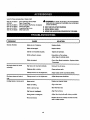
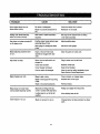
Troubleshooting.........................................................................................................................................................
46-47
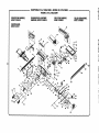
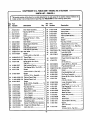
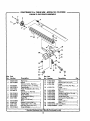
Exploded View ...........................................................................................................................................................
4-8-57
Parts Ordering/Service......................................................................................................................................
Back Page
ONE YEAR FULL WARRANTY ON CRAFTSMAN TOOL
If this Craftsman tool fails due to a defect in material or workmanshipwithin one year from the date of purchase,Call
1-B00-4-MY-I-IOME O to arrange for free repalr.If thls tool is used for commercial or rental purposes, this warranty will
apply for only ninety days from the date of purohass. This warranty appiles only while this product is in the United States.
This warranty gives you specific legal rights, and you may eJso hays other rightswhich vary from stats to state.
Seam, Roebuck and Co., Dept. 8t7WA, Hoffman Estates, IL 60179
This tool has many features for makingits use more pleasant and enjoyable. Safety, performance, and dependability
have been giventop priorityin the design of this productn'_.kingit easy to maintain and operate.
2
_k
WARNING." Reed and understand all insb'uetions, Failureto re[low all instruckions{istadbelow,
may resuttin electric shock, fire andlor serious
personal injury.
READ ALL iNSTRUCTIONS
•
•
•
•
•
•
•
KNOW YOUR POWER TOOL. Read the operator's
manual carefully.Learn the saw's applicationsand
Iimftations
aswet[ es the specific potenti_ hazards
related to this tool.
GUARD AGAINST ELECTRICAL SHOCK BY PREVENTING BODY CONTACT WITH GROUNDED
SURFACES- For examp}e,pipes, radiators, ranges,
refrigeratorenclesures.
KEEP GUARDS IN PLACE and in good working order.
REMOVE ADJUSTING KEYS AND WRENCHES.
Form habit of checking to see that keys and adjusting
wrenches are removedfrom tool before turningit on.
KEEP WORK AREA CLEAN. Cluttered areas and
benches inviteaceidents. DO NOT leave tools or
pieces ot wood on the saw while it is in operation.
DO NOT USE IN DANGEROUS ENVIRONMENTS.
Do not usepower tools in damp or wet locationsor
expose to rain. Keep the work areaweI_s_.
KEEP CHILD REN AND VISITORS AWAY. All visitors
shouldwear safety g_aesasand be kept a safe
distancefrom work ares. Do not let visitors osntact
tool or extensioncord while operating.
•
MAKE WORKSHOP CHILDPROOF with padlocks and
master switches, or by removings_,_'terkeys.
• DON'T FORCE TOOL. It will do the job better and
safer at the feed rote for which it was designed.
• USE RIGHT TOOL, Don't rome the tool or attachment
to do a job it was not designedfor. Don't use it for a
purposenot intended.
• USE THE PROPER EXTENSION CORD. Make sure
your extension cord is in good condition. Use on[y a
cordheavyenoughto carrythecurrent
yourprodu_
will draw. An undersizedcord will cause a drop in line
voltage resultingin _oesof power and overheating.A
wire gauges'_e (A.W.G.)of at least 14 is recommended
for an extensioncord 25 feet or less in length. If in
doubt, use thenext heavier gauge. The smallerthe
gauge number, the heavierthe cord.
• DRESS PROPERLY. Do not wear loose clothing,
gloves, neckties, or jewelry. They can get caught
and draw you intomoving parts. Rubber glovesand
nonskidfoo[wser are recommendedwhen working
outdoors.Alse wear protecl:'Nehair osver;ng to contain
long hak.
• ALWAYSWEAR SAFETYG_ESWITI-I
SIDE
SHIELDS. Everyday eyeglasseshave onlyimpactresistantlenses, they are NOT safety gtaseas.
• SECURE WORK, Use clamps or avise to hold work
when pc_ctical._fs safert_n using your han_ an
_ees both hands to operate tool.
• DON'T OVERREACH. Keep properfootingand
ba_nco at sit times.
•
•
•
•
•
•
•
•
•
•
•
•
•
•
MAINTAIN TOOLS WITH CARE. Kesp tools sherp
and clean for better and safer performanca.FoJiow
instructionsfor lubricatingand changingaccessories.
DISCONNECT TOOLS. When not in use, before
servicing,or when changingaLl_chmants,blades, bits,
cutters, etc., an tools should be disconnected.
AVOID ACCIDENTAL STARTING. Be sure switch is off
when plugging in any tooL
USE RECOMMENDED ACCESSORIES. Consult the
operator'smanual for recommendedaccessories.The
use of improperaccessoriesmay risk injury.
NEVER STAND ON TOOL, Serious injurycould occur
if the tool is tipped or if the cuttingtoo[ is unintention_lly con_.cted.
CHECK DAMAGED PARTS. Before further use of
the toot,a guard or other part that is damaged should
be carefuttychecked to determine that it will operate
propedyand perform its intendedfunction. Check for
al{gnn_nt
of movingparts, b(n_ing
ot movingparts,
breakageof parts, mounting and anyother conditioP.s
that may affect its oparatien. A guard or o_er part _at
is damaged must be properlyrepairedor replaced by
_.nau'thofized service centerto avoid risk of personal
ir_u_
USE THE RIGHT DIRECTION OF FEED. Feed work
into a blade or cutler against the directionot rotation of
bladeor cutter only.
NEVER LEAVE TOOL RUNNING UNATTENDED.
TURN THE POWER OFF. Don't leave tool until it
comes to a complete stop,
PROTECT YOUR LUNGS. Wear a face or dust mask if
the cutting operation is dusty.
PROTECT YOUR HEARING.Wear'hearing protection
dorJng exte_de_ periodsofopera,on,
DO NOT ABUSE CORD. Never yank cord to disconnect from receptacle. Keep cord from heat, oil, and
sharp edges.
USE OUTDOOR EXTENSION CORDS, When tool
is used ou_oore, use onlyextensbn cordswith
approved ground osnne_ion tha_are intended for use
outdoors and so m_rked.
ALWAYS KEEP THE BLADE GUARD AND RIVING
KNIFE/SPREADER/SPLITTER IN PLACE and in
working order.
KEEP BLADES CLEAN, SHARP, ANDWITH
SUFFICIENT SET. Sharp blades minimize stalling
and kickback.
• KEEP HANDS AWAY FROM CLrt-r|NG AREA. Keep
hands away from blades. Do not reach underneath
•
•
•
•
•
•
•
•
•
work or around or over the blade while blade is
rotating. Do not attempt to remove cut material when
blade is moving.
BLADE COASTS AFTER BEING TURNED OFF,
NEVER USE IN AN EXPLOSIVE ATMOSPHERE.
Normal sparking of the motor Gould ignite fumes.
INSPECT TOOL CORDS PERIODICALLY. If damaged,
have repaired by a qualified service technicianat
an authorizedservice facility.The conductorwith
insulationhaving an outer surfase that is green with
or without yellow sl:ipes is the equipment-ground[ng conductor.If repair or replacement of the electric
cord or plug is necessary,do not connect the equipment-grounding conductor to a live terminal.Repair
or replace a damaged or worn cord immediately.Stay
constant_j aware of cord location and keep itwen away
from the rotatingblade.
INSPECT EXTENSION CORDS PERIODICALLY and
replace if damaged.
GROUND ALL TOOLS. if tool is equipped with threeprong plug, it should be plugged into a thrse-ho_e
electrical race,oracle.
CHECKWlTH A QUALIFIED ELECTRICIAN or service
personnelif the 9rounding instructionsare not completely understoodor if in doubt as to whether the tool
is properly 9rounded.
USE ONLY CORRECT ELECTRICAL DEVICES: 3-wira
e0_.tansion
cords that have 3-prong groundingplugs and
3-pole receptaclesthat accept the tool's plug.
DO NOT MODIFYthe plug provided. If it will not fit the
outlet, have the proper outlet installed by a quatified
etectndan.
KEEP TOOL DRY, CLEAN, AND FREE FROM OIL
AND GREASE. Always use a c_eancloth when clean-
•
•
•
•
•
•
ing. Never use brake fluids, gasoline,pe_'oleum-based
products, or any soWantsto clean tool.
STAY ALERT AND EXERCISE CONTROL. Watch
what you are doing and use common sense. Do not
operate tool when you are tired. Do not rush.
DO NOT USE TOOL IFSWlTCH DOES NOT TURN IT
ON AND OFF. Have defective switchesreplaced by an
authorizedservtce center.
USE ONLY CORRECT BLADES. Do not use blades
with incorrect size holes. Never use blade washers or
blade bo{Lsthat ere defective or incorrect.The maximum blade capacity of your saw is 10 in. {254 ram).
BEFORE MAKING A CUT, BE SURE ALL ADJUSTMENTS ARE SECURE.
BE SURE BLADE PATH IS FREE OF NAILS. inspect
for and remove all nails from lumber before cutting.
NEVER TOUCH BLADE or other moving parts during
USe.
•
•
NEVER START A TOOL WNEN ANY ROTATING COMPONENT IS IN CONTACT WITH THE WORKPIECE.
DO NOT OPERATE A TOOL WHILE UNDER THE
INFLUENCE OF DRUGS, ALCOHOL, OR ANY
MEDICATION.
• WHEN SERVICING use only identica]replacement
parts. Use of any other parts may create a hazard or
cause product damage.
• USE ONLY RECOMMENDED ACCESSORIES listed
in this manual or addendums. Use of accessories
that are not listed may cause the risk of personal
injury. Instructions for safe use of aecsseorias are
Inciuded with the accessory.
• DOUBLE CHECK ALL SETUPS. Make sure blade is
tight and not trek(rig contact with saw or workpieca
before connecting to power supply.
• GUARD AGAINST KICKBACK. Kickback occurs
when the blade stalls rapidly and workplace is driven
beck tow_ds the o_arator. It can pull your h_nd (nto
the blade resultingin serious personalinjury.Stay out
oi blade path and turn switch off immedi_ely if blade
bindsors_iis,
• USE RIP FENCE. Always use a fence or straight edge
guidewhen Hpping.
• SUPPORT LARGE PANELS. To minimize risk of blade
pinchingand kickback, always support large panels.
• REMOVE ALL RENCES AND AUXILIARY TABLES
before transpo_ng saw. Failureto do so can result in
an accidsn.tcausing pose_le serious personalinjury.
• ALWAYS USE BLADE GUARD, RMNG KNIFE/
SPREADEPJSPLrl-rER, AND ANTI-KICKBACK
PAWLS on 81[=through-sawing =operations. Through-
sawing operations are those Inwhich the blade outs
completely through the work.pieceas in rippingor
crass out_r,g. Keep the b_de gu_-d down, th_ _ntikickback pawls down, and the rivingkrdfe/spreader/
splitter properly alignedto '_e saw blade.
• ALWAYS ,RECURF.WORK firmly against rip fence,
miter fence, or miter gauge.
• ALWAYS USE A PUSH STICK FOR RIPPING NARROW STOCK. A push stick is a device used to push
a workplace through the blade instead of using your
hands. Size and shape canvary but the pushstick must
always be narrowerthan the work,piece to prevent the
push stick from contacting th_ saw blade. When ripping
narrowstock, always usaa pushstick,so yourhand does
not come closeto ths sew blade. Use a fea_herbeard and
push blocks for non-throughouts.
4
•
NEVER perform any operation =freehand" which
means using onlyyour hands to support or guide the
workplace. AJwaysuse either the rip fence or miter
fence to positionand guide the work.
interferewith safe operationBEFORE performingany
work usingthe table saw.
I
ALWAYS TURN OFF SAW before disconnectingit, to
avoid accidentalstarting when reconnectingto power
supply.
ROUTER ACCESSORY SAFETY RULES
• ALWAYS DISCONNECT SAW FROM POWER SUPPLY BEFORE MAKING ADJUSTMENTS OR ADDING
ACCESSORIES. Make sure the switch is off when
reconnecting to power supply.
• ALWAYS FEED WORKPIECE AGAINST THE ROTATKIN OF THE CUTTER.
•
NEVER stand or have any part of your body in line
with the path of the saw blade.
• NEVER reach behind, over,or within three inches of
the blade or cutter with either hand for any reason.
• MOVE THE RIP FENCE cut of the waywhen cruse
cutting.
• NEVER use rip fence as cutoff gauge when cross
cutting,
• DO NOT USE AWKWARD HAND POSITIONS.
• NEVER attempt to free a stalled saw blade without
first turning the saw OFF and disconnectingthe saw
from the power source.
• PROVIDE ADEQUATE SUPPORT to the rear end
sides of the saw table for wide or longwork pisces.
Use a sturdy "outrigger" support if a table extension
more than 24 inches tong 'Isattached to the saw.
• AVOID KICKBACKS (work thrown back toward you)
• KEEP FINGERS AWAY f_om therevolving cutter,and
use fixtureswhen necessary.
• ALWAYS USE THE DUST COVER for overhead
guarding.
• DO NOT REMOVE JAMMED CUTOFFPIECES until
cutter or blade has stopped and tool has been
disconnected from power source.
• HOLD THE WORKPIECE FIRMLY AGAINST THE
TABLE.,
b_r.
a) Keeping bladesharp.
b} Keeping r{pfence parallelto the saw blade.
c) Keeping riving knife/spreader/splitter,ant_-kickback
pawls, and blade guard In plase and operating.
d) Not retsasingthe work before it is pushed a_lthe
way past the saw blade usinga pushstick.
e) Not tipping work that is twisted or warped or does
not have a straight edge to guide along the fence.
• AVOID AWKWARD OPERATIONS AND HAND
POSITIONS where a sudden slip could cause your
hand to move into the cuttingtool.
• USE ONLY RECOMMENDED ACCESSORIES listed
in this manual or addendums. Use of accessoriesthat
are not listed may causethe risk of personal in'fury.
Instructionsfor safe use of accessoriesareinc(uded
with the accessory.
• MAKE SURE THE WORK AREA HAS AMPLE LIGHTING to see the work end that no obstructionswill
_
• ALWAYS USE THE SAW'S MASTER SWITCH TO
TURN TIlE ROUTER ON AND OFR
•
THIS TOOL shouldhave the fo2low'_ng
markings:
a) Wear eye protection.
b) Use saw bla.deguard and rivingknife/sprsadsd
splitterfor every operation for which it can be
used, including all through sawing.
c) Keep hands out of the line of saw blade.
d) Use a pushstickwhen required.
e) Pay particular attention to instructions on reducing
Iisk otkickback.
f) Do notperform any operationfreehand.
g) Never reach around or over the saw blade.
• SAVE THESE INSTRUCTIONS. Refer to them
frequently and useto instruct other users. If you loan
someone thLstool, Joanthem these instructJona also.
WARNING: Some dust created by power sanding, sawing, grinding,drilling,and otherconstructionactiv_ies
contains chemicals known to cause cancer, birth defects or other reproductiveharm. Some examples of these
chemicals are:
•
lead from Isad-based paints,
*
crystallinesilica from bricks and cement and other masonryproducts, and
= arsenic and chromiumfrom chsmicatly-_'satedlumber.
Your risk from these exposures varies,depending on how often you do this type of work. To reduce your exposure
to these chemicals:work in a well ventilatedarea, and work with approved safety equipment, such as those dust
masks that are specialtydesignedto f_lterout microscopicparticles.
5
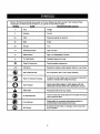
Some of the following symbolsmay be used on this tool. Please study them and learn their meaning. Proper
interpretationof these symbolswill allow you to operate the tool better and safer.
SYMBOL
NAME
DESIG NATION/EXPLANATIO N
V
Volta
Voltage
A
Amp_es
CuTrent
Hz
Hertz
Frequency(cyclesper second)
W
Watt
Power
Minutes
Time
"x.,
Affemating
Current
Type ofcurrent
_,
DirectCurrent
Type or a characteristicof current
no
No Load Speed
Rotational speed, at no load
[]
Class U Construction
Double-insulatedconstruction
•.Jmin
Per Minute
Revolutions,strokes,surface speed, orbits etc., par minute
(_
Wet Conditions
Alert
Do not expose to rain or use in damp locations.
Read The Operator's Manual
To reduce the
operator's
manual
risk before
of injury,user
using this
must
product,
read and understand
rain
O
Eye Protection
Always and
wearasafety
goggles
or safety
g_Lqses
withproduct,
aide
shields
full face
shieldwhen
operating
this
Sa_e_ Alert
Precautionsthat involve yoursafety.
No Hands Symbol
Failureto
serious
personalinjury.
keepyour hands away from the blade wi|i result in
Pinch Warning
potential areas where pinchingcould occur.
Hot Surface
To
reduce
the risk
of injuryorpaying
damage,
avoid
contact with
Always
watch
for movement
exVa
attentionto
any hot sudaoa.
ii
(_
6
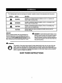
The following signetwords and meanings are intendedto explain the levels of risk associated with this product.
SYMBOL
A
SIGNAL
MEANING
DANGER:
Indicates an imminentlyhazardoussituation,which, if not avoided,will
result in death or seriousinjury.
WARNING:
Indi_at_a potentiallyhazardoussituation, which, if not avoided, could
result in death or seriousin}ury.
CAUTION:
Indir_tas s potentisl{y hazardoussituation,which, if not avoided, may
result in minor or moderate injwy.
CAI_'ION:
(Without Safety AlertSymbot)Indicaies a situationthe.tmay resultin
property damage.
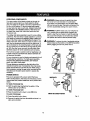
SERVICE
_k
Servicingrequires extreme care and knowledge and
should be performed only by a qualified service technician. For servicewe suggest you returnthe product to
your nearest AUTHORIZED SERVICE CENTER for repair.
When servicing, use on}yidenticalreplacement parts.
WARNING" To avoid serious personal injury,do not
attempt to use this product until you read,thoroughty
and understand completely the operator's manual.
Save this operator'smanual and review h'equentty for
continuingsafe oparat_on
and instructing otherswh_
may use this product.
WARNING:
The operation of any power tool can resultin foreign objects being thrown intoyour eyes, which can
result insevere eye damage. Before beginning power tool operaf3on,aJwayswear safety goggles or
safety glasseswith side shields and a full face shieldwhen needed, We recommend Wide VisionSafety
Mask for use over eyeglasses or standard safety glasseswith side shields,Always use eye protection
which is marked to comply with ANSI Z87.1.
SAVE THESE INSTRUCTIONS
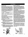
EXTENSION
CORDS
Use oniy3-wirs extensioncords t_et have 3-prong grounding plugsand 3-pole receptaclesthat accept the tool's plug.
When usinga powertoolat a considerabledistancefromthe
powersource, use an extensioncordheavy enoughto carry
the current that the tool will draw. An undersizedextension
cord will cause a drop in line voltage, resulting in e loss of
power and causing the motor to overheat. Use the chart
providedbelow to determine the minimum wire size required
in an extension cord. Only round jacketed cords listed by
Underwriters Laboratories(UL)should be used.
• "Ampere re,ling(on tool dab= plate)
0-2.0
Cord Length
25'
"_6
2.1-3.4
16
3.5-5.0
5.1-7.0
7.1-12.0
Wire Size (A.W.G.)
"_6
t6
14
12.1-16.0
14
50'
16
16
16
14
14
12
100'
1'6
1'6
1'4
1'2
10
--
-Used on 12 gauge- 20 amp circuPL
NOTE: AWG = American Wire Gauge
When workingwith the too] outdoors, use an extension
cord that is designed for outside use. This is indicated by
the letters "WA"on the cord'sjacket.
Before using an extension oord, inspect it for loose or
exposed wires and cut or worn insulation.
WARNING: Keep the extension cord deer of the
working arcs. Position the cord so that it will not get
caught on lumber,tools or otherobstructionswhile
you are workingwi.itna power toot. Failureto do so
can resultin serious personal injury.
•_
,_
WARNING:
Check extension cordsbel:oreeach use.
ELECTRICAL CONNECTION
This too[ is powered by a precisionbuilt electricrootor.
It shouldbe connected to a power supply t_at is 120
volts, 60 Hz, A¢ only (normal household currentJ. Do
not operate this toot on directcurrent (DC). A substantial
voltage drop will cause a loss of power and the motor will
overheat, fftha saw does not operatewhen plugged into
an outlet, double check the power supply.
SPEED AND WIRING
The no-load speed of this tool is approximately 4,800 rpm.
Thissbeed is not constant and decreases under a load or
with lower voltage. For voltage, the wiringin a shop is as
important as the motor's horsepowerratlt_. A Lineintended only for lights oannot properly carry a power tool motor.
Wire that is heavy enough for a shortdis_nce wi!!be too
light for a greater distance.Ailne that can support one
power tool _ay not bs able to support two or three tools.
GROUNDING INSTRUCTIONS
In the eventof a malfunctionor breakdown,grounding
providesa path of least raslstanoefor electriccurrent to
reduce the risk of electric shook.]his tool is equipped with
an electriccord havingan equipment-groundingconductor and a groundingplug. The plug must be plugged intoa
matching outlet that is properly installedand groundedin
accordancewith all localcodes and ordinances.
Do not modifythe ptug provided. It It will not fit the outlet,
have the proper outlet installed by e qualified alectrlalan.
_mpropercanneot_onof theequipment-groundingconductor
can result in a dsk st electric shock. ]'he conductor with
Insulationhavingan outersurfacethatIs greenwith orwithout
ye,ow stripesis theequ|pment-groundlngconductor.It repair
or replacement of the electric cord or plug is necessary,do
not connect the equipment-groundingconductor to a live
terminal
If damaged replaceimmediately.Never usetool with a
damaged cordsince touchingthe damagedarea could
cause electricalshock resulting in sedous injury.
Check with a qualified electrlc_n or s_rvice personnelff
the groundingInstructionsare not completely understood,
or it in doubt as to whetherthe tool Lsproperbjgrot_nded.
WARMING: The saw's motor cord must only be
pluggedintothe receptacle providedonthe saw which
is controlledby the saw's master switch. Never plug
the motor cord d_'ectty"intoan extension cord as this
wi_ stop the saw's motor from turning OFF.
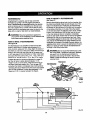
Repair or rsplacaa damaged or worn cord Imroedtately.
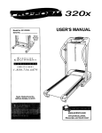
This tool is intended for use on a ch'cuitthat has an outtet
like the one shown in figure 1. It also has a groundingpin
llke
theone shown.
SAW
RECEPTACLE
MOTOR
POWER
PIN
8
120V GROUNDED
OUTLET
FJG.1
Anti-Kickback Pawla (radial arm and table saws)
A device which, when properlyinstalledand maintained,
is designed to stop the wcrkpisee from being kicked back
toward the front of the saw duringa rippingoperation.
Arbor
"Theshaft on which a brads or cu_}ng tool is mountsd.
Bevel Cut
A cutting operation made w]th the blade at any angle
other than 90° to the table surPace.
Non-Through Cuts
Any cutting operationwhere the blade does not extend
completelythrough the thickness of the workplace,
Push Blocks and Push 8ticks
Devices used to feed the workpiece through the saw
biade duringcutting operations.A push stick (not a push
Mock) should be usedfor narrow ripping operations.
These aids help keep the operator'shands w_l away frccn
the blade.
Chamfer
A cut removing a wedge from a blockso the end (or part
of the and) is angled ratherthan at go°_
Pilot Hole (drill presses)
A small hole drilled in a workpie_ that serves as a guide
for drillinglarge holes accurately.
Reeaw
A cutting operetiento reduoathe thickness of the workpiece to make thinnerpieces,
Resin
A sticky,sap-based substancethat has hardened.
Compound Cut
A cross out made with bert1a miter and a bevelangle.
Cross Cut
A cutting or shap]ng operation made across the grain or
the width of the workpisce.
Cutter Head (planers and Jointera|
A rotatingpiece of ad}ustabla blades. The cutter head
removes material from the warkpiece.
Dedo Cut
A non-throughcut which producesa square-sided notch
or bough in the workplece (requiresa special blade).
Featharboard
A device used to help centre] the workpless by guidingit
securelyagainst the table or fence duringany ripping
operation.
FPM or $PM
Feetperminute(orstrokesperminute),
usedinreference
toblademovement.
Revolutions Par Minute {RPM)
The number ofturnscompletedby a spinning
objectin
one minute.
Ripping or Rip Cut
A cutting operationalongme length of the work.piece.
Riving Knifa/_prsader/Splittar (table saws}
A metal piece, slightly thinnerthan the blade, which helps
keep the kerr open and a{sa helpsto prevent k.Jckback.
Saw Blade Path
The area over, under,behind, or in front of the blade. As
it applies to the workplece,that area which will be or has
been cut by the blade.
Sat
The distancethat the tip of the saw blade tooth is bent (or
set:}outward from the face of the blade.
Snipe (planers)
Depression made at e_her end ofa workplace by cutter
blades when the workplace is not properlysupported.
Throw-Back
The throwing back of a worl(plece usuallycaused by the
workplace being dropped into the blade or being placed
inadvertentlyin contact with the blade.
Freehand
Performinga cut without the workpiece being guided by a
fence, miter gauge, or other aide.
Gum
A stick'34,
sap-based residue from wood products.
Heel
Alignment of the blade to the fence.
Karl
The material removed by the blade In a throughcut or the
slot produced by the b!ade in a non-throughor partial cut.
Kickback
A hazard that can occur when the blade binds or stalls,
throwingthe workplace back toward operator.
Leading End
"Theend of the workp'lecepushed into the tool first.
Mltar Cut
A cutting operation made with the workplace at any angle
to the blade other than 90 °.
Through SaWing
Any cutting operationwhere the blade extends completely
through the thickness of the workplace.
Workplace or Materiel
The item On which the operation is being done.
Worktabta
Surface where the work.piecerests white performinga
cutting, drilling,planbg, or sanding operation.
g
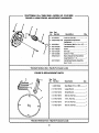
PRODUCT SPECFICATIONS
Blade Arbor .............................................................. 5/8 in.
Blade Diameter.......................................................... 10 in.
Blade Tilt ................................................................. 0° - 45"
Net Weight Without Leg Stand ................................ 85 Ibs.
Net Weight With Lag Stand................................... 110 Ibs.
Rating ............................................. 120 V, 60 Hz - AC only
Input ................................................................ 15 Amperes
No Losd Speed .............................................. -..4,800/rain,
Cutting Depth at 0": ............................................. 3-9116 in,
Cutting Depth at 45": ............................................. 2-1/2 in,
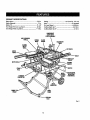
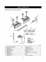
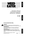
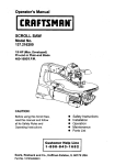
GUARD/DUST
COVERWITH
PIVOTASSEMBLY
•AHTI-KICK)BACI[
PAWI.S
BLADE
GUARD
ACCESSORY
TABLE
SI.IOING
MITER
TABLE
RIPFENCE
SCALE
ALIGN-A-CUT
INSERT
LOCKING
HANDLE
FRONT
RAIL
HEIGHT/BEVEL
ADJUSTING
HANDWI_EL
STORAGE
DRACI_T(S}
BEVEL
INDICATOR
BRACE
LEVEL|NE
FDDT
Fig. 2
10
HEIGHT/BEVEL ADJUSTING HANDWHEEL - Located
on the front of the cabinet, use this handwheal to lower
and raise the blade for height adjustmentsor blase
replacement. This f_ndwhea( also makes the adjustment
for bevel ang[as easy.
LEG STAND - Attached to the table saw base, the leg
stand opens and closes with ease.
MITER FENCE- The fence attaches to the slidingmiter
table and can be angled for miter and compound miter
cuts as wall as straight cuts such as cross, bevel cross,
rip, and bevel rip cuts.
KNOW YOUR TABLE SAW
See Figure 2.
Before attempting to usethis product, familiarize yourself
with air operatingfeatures and safety rules.
ACCESSORY TABLE - The accessory table may be used
on either the right or left side of the saw as needed and
has been designedfor use with some reuters. A router
mounted on the accessorytable wilrprovide expanded
capabilities for making rabbets, grooves, chamfers,dovetails, and mortiseand tenon joints.
ADJUSTING CLAMP - This clamp looksthe miter fence
stthedesired
curingangla.
ALIGN-A-CUT INSERT - A plastic insert on which marks
may be made to indicate the locationof the saw cut on
the workplace.
ANTI-KICKBACK PAWLS - Kickback is a hazard in which
the workplace is thrown back toward the operator.The
teeth on the anti-kickback pawls point away _om the
workpiece. If the workpiecs should be putisd back toward
the operator, the teeth dlg intothe wood to help prevent
or reduce the possibility of kickback.
MITER GAUGE - The miter gaugealigns the wood for
a cross cut. The easy-to-read indicatorshows the exact
angle for a miter cut, with positivestops at 90° and 45 °.
MITER GAUGE GROOVES - The miter gauge rides in the
grooves on the accessory table.
MOTOR - The powerful inductionmotor,with capacitor
start and V-belt drive, is housed in a sturdysteel base.
RA]L_ - Front end rear railsprovide support for large
workpiecas and the rip fence.
RIP FENCE - A sturdy metal fence guidesthe workplace
and is securedwith the locking handle.Grooves runalong
the top and sides of the rip fence for use with optional
clamps and accessories.
BEVEL SCALE - The easy-to-raad scale on the frontof
the cabinet shows the exact blade angle.
BLADE - This saw is provided with a 36-tooth, 10 in.
carbideblade.
The blade is raised and lowered with the
height adlusting handwheeLBevel angles are lockedwith
the bevel lockinglever.
A
RIVING KNIFE/SPREADER - A metal piece of the blade
guard assembly, slightly thinner than the saw blade,
which helps keep the ked open and prevent kickback.
SCALE - Located on the front rail, the easy-to-readst;ale
provides precisemeasurements for dp cuts.
SLIDING MITER TABLE - The miter table slideseasily
along the miter table base ailowlng the operator to move
the warkpiece across the saw table.
WARNING: Do not use blades rated _easthan the
speed of this tool. Failureto heed this warning could
resultin personalinjury.
BLADE GUARD - Always keep the blade guard down
over the saw blade for through-sawing cuts.
SWITCH/_SEMBLY - This saw has an easy access
powar switch located below the front rm_.To lock the
switch in the OFF position,remove the switch keyfrom
the sw_tch.Place the key in e location that is inaccessible
to children and others not qualifiedto use the tool
BEVEL LOCKING LEVER -This lever, placed just under
the saw table surface on the frontof the cabinet, {coke the
angle setting of the blade.
11
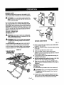
OPERATING
COMPONENTS
Am, WARNING: Atwaysremove the switch kay when
the tool L_not m use and keep it in a sate ptsce.
In the event of a power f_zLlure,
turn the switch OFF
( O ) 8.ridremove the key.This action will preventthe
tool _rom aoc_dsntalty st_tln 9 when power returns.
The upper portion of the blade projects up through the
table and is surroundedby an insertcalled the throat
prate.The height of the blade is sat with a handwhsel on
the front of the cabinet. To accommodate wide panels,
the saw table has rails on each side. Detailed instructions
are provided in the Opera,on section of this rnanualfor
the basic cuts: crosscuts, miter cuts, bevel cuts, and
compound ¢U_l
The sliding
mitertableaseemblyisused forcrosscutting
operatfens.
The miterfenceiseasily
adjusted
tocutwood
at an angle by looseningthe adjusting clamp, setting the
fence to the miter scale, and retightening the clamp. The
stlding miter table, which restson a base mounted on the
rails, can be repositfehedalong the mils for wide work. _t
can be reversed so the projectingbase is in the back and
can be moved from the left side to the right side as needed. With _a miter fence removed, the miter table offers
additions]support"for other operations such as ripping.
The rip fence is used to positionwork for lengthwisecuts.
A scale on the front rail shows the distance between the
ripfence and the blade.
_'
WARNING: ALWAYSmake sure your workpisce is
not in contact with the b(ade before opsrat(ng the
switch to startthe tool. Faitureto heed this warning
may cause the workpieca to be kicked back toward
theoperator
aridresult
it_
serious
_rsor_iinjury.
_lz
WARNING: To reduce the risk of accidental starting,
Always make surethe switchis in the OFF ( O ) position
before pIugging tool into the power source.
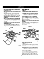
SWTfCH
ON
SWITCH
OFF
it is very importantto use the blade guard assemblyfor all
through-sewing operations.The blade guard assembly
includes:riving knife/spreader/splitter, anti-kickback
pawls, and plastic blade guard.
The saw features a receptacle on the right side of the
cabinet that permitsuse of accessories. Use onlyaccessories that are listed for use with this tool When usinga
listed accessory, unplug the saw motor cord and usa the
receptacle and the saw'-, power switch to operate the
accessory.
POWER SWITCH
This saw is equipped with a power switch that has a
built-in locking feature. This feature is intendedto prevent
unauthorizedand possible hazardoususe by chUdrenand
others.
SWITCHKEY
TO TURN YOUR SAW ON:
• With the switch kay inserted into the switch, tilt the
switch bu_tonto turn ON ( I ),
TO TURN YOUR SAW OFF:
• Press the switch button down to turn OFF ( O ).
TO LOCK YOUR SAW:
•
SWITCHIN LOCKED
POSITION
Press the switch button down.
Fig. 3
• Remove the switch kay from the switch and store in a
safe, secure location.
12
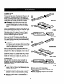
BLADES
Formaximum
A
performance, it is recommendedthat you
use the Craftsman 36-tooth, 10 in. carbide combination
blade provided with your saw. Additionalblade stylesof
the same high quality are availablefor specific operations
such as ripping.Your local dealer can provideyou with
complete information.
WARNING:
Do not use blades rated less than the
speed of this tool. Faitureto heed this warning could
resultin personalinjury.
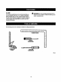
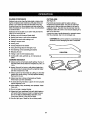
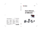
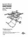
The f#,lowing toots (not inoLudsd)are needed,for makingadiustments:
COMBINATION
SQUARE
FLATBLADE
SCREWDRIVER
Fig. 4
13
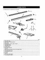
Thefollowing
items are included with your table saw:
G
Fig. 5
i
A.
B.
C.
D.
E.
E
G.
H.
I.
J.
K.
L
M.
N.
O.
P.
Sliding MiterTable .......................................................................................................................................................
Miter Fance with AdjustingClamp ..............................................................................................................................
Miter Gauge ......................................................................................................................... ........................................
Hex Key (1/8 In., 3/16 in., 2/32 (n., 5/32 In.)................................................................................................................
Large Btada Wrench ....................................................................................................................................................
Small B[adeWrench ....................................................................................................................................................
AccessoryTable ..........................................................................................................................................................
I_vel Hartdle Assembly..............................................................................................................................................
Rip Fence ....................................................................................................................................................................
Blade Guard with RivingKnife and Anti-Kickback Pawls ...........................................................................................
End Cap {Front Rail, Left)............................................................................................................................................
End Cap (Roar Rail, Left).............................................................................................................................................
Front Rail.....................................................................................................................................................................
Rsar Rail.....................................................................................................................................................................
End Cap (Front Rail, Right)..........................................................................................................................................
End Cap (Rear Rail, Right)...........................................................................................................................................
14-
1
1
1
4
1
1
1
1
1
1
1
1
1
1
1
Thefolidwing
items are includedwith your table saw:
@
D
F
d
Fig. 6
A.
Guide Fence w_thGuide Block............................... 2
J.
B.
C.
Flat Washer (1/4 in. x 16) ........................................ 4
Knob Bolt (1/2 In.) ................................................... 4
K. Throat Plats (1/2 in.)................................................ 1
L. Screw, #10 In.-32 x 3/4 In ....................................... 3
M. Screw, 5/16-18 in. x 3/4 in ...................................... 3
D. Table Clamping Bracket.......................................... 1
E. Washer(5/16 in.)..................................................... 1
Throat PLate[1-1/8 in.) ............................................ 1
N.
Screw, M8 x 24 ....................................................... 4
Knob Bolt (3/4 in.)................................................... 1
O.
Guard/Dust Coverwith Pivot Assembly................. 1
G. Throat Prate (1 in._................................................... 1
H. Throat Plate (1-1/2 in.)............................................ 1
P.
Q.
Spacer..................................................................... t
Post......................................................................... 1
I.
R.
T-N_t, 5(16 in. _Spec(a0........................................... 6
F.
Throat Prate(2 its.)................................................... 1
15
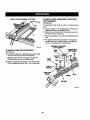
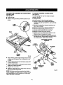
UNPACKING
Thisproduct requiresassembly.
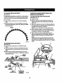
•
• Once the leg stand is released from the release lever,
ease the leg s_n rttoward the _ocr by pashlngth_ grips
toward the floor.
• Withyourhandsonthegr_ps, pushthslegstand_owards
the ground untilthe _.bis saw is in an upright pos'_tion.
NOTE: The release leverwill close over the center brace
lockingthe leg stand in an upright poslton.
• Carefully lift the asw from the carton and place it on a
level work surface.
•
•
•
•
_"
Step on the release ]everand pull the grips toward you
at the same time.
NOTE=This tool is heavy.To avoid back injury,keep
your knees bent and lift with your legs, not your back,
and do not lift saw without help.
Inspect the tool carefullyto make sure no breakage or
darnags occurred duringshipping.
Do not discard the packing material untilyou have
caref_Jttyinspected and sstistacto_tyoperated the too_.
The _aw is factory set far accurate cutt'_ng.After
assembling it, check for accuracy.If shipping has
influenced _e settings, refer to specificprocedures
expta'medin _is manual.
If any parts are damaged or missing, plasea call
1-800-932-3188 for ass]stance.
WARNING: if any parts are missing, do not operate
th_s too_ unt_the missing parts are replaced. Failure
to do so could rssultin possibleserious personal
injury.
_1= WARNING: Do not attempt to modify this tool
or create accessories not recommendedfor use
with this tool. Any such aiteratlonor modification is
misuse and could resultin a hazardous condition
leading to possible se_oL;spersonalin)ury.
A
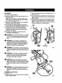
SAW
BASE
GRIPS
RELEASE
LEVER
WARNING: Do not connectto power supply until
assembly is complete. Fa(lursto comply could result
in accidental starting and possible seriouspersonal
injury.
LEG,STAND
Fig. 7
_1= WARNING: Do not lift the saw without help. Hold
it close to your body. Keep your knees bent and
(iftwith yourlegs, not your back. Ignoringthese
precautions can resultin back injury.
A
Am, WARNING: Never stand d}rs_')yin line with the
blade or allow hands to corns closer than 3 in. to the
blade. Do not reach over or across the blade. Failure
to heed this warning can resultin serious personal
iniury.
A
me, WARNING" To avoid seriouspersonal injury, always
make sure the table saw is securely mounted to
this leg stand. NEVER remove the saw from the 1eg
stand.
TO OPEN THE LEG STAND
See Figures 7- 8.
cENTER
BRACE
• Grasp the grips on the saw table and s_and it upright as
shown in figure 7 be(ow.
Fig, 8
16
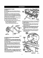
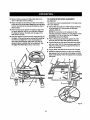
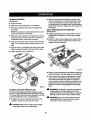
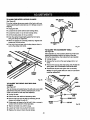
TOSECURE/LEVEL
THESAW
See F-igum9.
With the leg stand open and the table saw resting on a
fiat, level surface, the saw shou]d not move or rook fl'om
side to side.
MZTER
ff the sew rests on the wheels and roils, [oosaneach
wheel stop by turning counterclockwise.The leg stand
should met on each stop only slightly.If the wheel stop is
turned too much, the stop will interferewith the opening
and closing motion of the leg stand.
if the saw rocks from side to side, the levelingfeet need
adiustlng until the leg stand is balanced.
RIPFENCE
Fig. 10
• Loosen both the top and bottomwing nuts.
• Lift the saw slightlyso that you may turn the kiveiin9
foot untilthe leg stand no longerrocks.
Stand facing the back of the table saw. The longest part of
the miter table base must be stored to the left. To secure
the sliding miter table:
• Turning ctookwise wilt lower thefoot
•Turning countarclockwisaw_llra'lsathe fog
•
Restthe slidingmiter table on the bottom right-hand
storage hook and +,hemiter base on the lower miter
bottom left-hand hook.
I
Alignthe bottom miter lookingcfe_npwith the bottom
left storage hock. Push the slidingm'rtertable back
toward the cabinet _zntilit is restingagainst all four
hooks.
•
Look the miter lookingclamps on the left by pushing
clamps toward the side of the oabinst securingthe
miter table in place.
WINGNUT
MI'IER
FOOT
Fig. g
STORAGE
HOOK
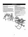
TO S'fORE THE TABLE SAW ACCESSORIES
See Figures 10. - 11
The table saw has two convenientstorage areas specifically designed for the saw's accessories. These accessories must be sooure_ystored priorto closing the leg stand
and moving the saw.
The rip fence, miter fence, and miter gauge shouldbe
stored in the brackets located on the side of the saw
cabinet. Simply snap each accessoryin place to hold _t
securely.
Storage hooks for the slidingmiter table are located on
the back of the saw cabinet. This storagearea is to be
used onlyfor moving the saw or when the saw is not
being used.
SLIDING
MITER
TABLE
NOTE: During operation of the saw, the slidingmiter table
must be mounted on the mile. NEVER operate the sew
with the sliding miter table in the storage position because
it blocksthe dust exhaust port.
STOP,
ABEHDDK
17
F_g;11
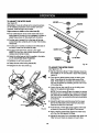
TO IN_rALL BEVEL HANDLE ASSEMBLY
See F-t_re 12.
•
Lift the end rap offthe bevel handle assembly usinga
fiat b|ade screwdriver,
•
Hold the nylonnut securelyand turn the screw counterclockwise toremove thenutcompletely.
NOTE: Do not remove the screw from the handle or the
washer from the end of the screw.
•
Place the nylon nut into the recessed holeon the back
of the height adjustinghandwheel and hold in place,
Slide the handle,screw, and washer into the hole on the
he(ghtadjustln9
l_n_'_heaL
•
•
Using a fiathead screwdriver, turn the screw clockwise
and tighten
inplace.
•
Push the end cap back in place on the end of the
handle.
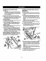
FRONTPAIL
SQUARE
RAIL
HOLDERNUT
WONTRAIL
cLAMP
Fig. 1"3
HEXNUT
HEIGHT/BEVEL
ADJUSTINGRANDWHEEL
BEVEL
HANDLE
WASHER
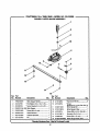
TO INSTALL FRONT AND BACK RAILS
See Figures 13 - 14,
•
SQUARE
RAIL
HOLDERNUT
Loosenthe front
rail ciarnps one half turn fi'omthe
tightened position. Loosen the square ragholder nut
one-fourth (1/4)
turn"_oallowthe front ra_to slide ovsr
it.
REARRAIL
CLAMP
Fig. 14
•
Mount the _ontrailwith thescale faoincj the outside
toward the operator.
• Check to make sure the rail clamps will securelyclamp
the rai( before slidingthe entire assembly into position.
If not, tighten the square rail holder nut one-fourth (1/4)
turn and recheck.
•
Slide the rail into position over both clamps and
secure.
•
Mount the rear rail, following the same ciamping
procedure as shown for the front rail
18
TO UNLOCK/MOVE
THERAILS
See Figure 15.
The front and back rails will need to be positionedso they
do not touch the floor when the Sagstand isclosed.
Using the bottom scale as a guide, the scalewill need to
be aligned to the saw blade at the 14 in. mark. To unlock
and move t_e mils:
• Loosen the front rali clamps by pushingthe lever to the
left.
• Slide the ra'dto the desired position.
•
Secure the rag in position by pushing the clamp to the
right.
•
Repeat shove steps with the rear rail plscingit in the
same locationas the front rail.
RELEASE
LEVER
NOTI:-' When the rails are moved to the right, use caution
to avoid trippingon the front leg brace.
IL
CLAMP
Fig. 16
_g. 15
TO CLOSE THE LEG STAND AND MOVE THE SAW
See Figure 16.
Store the slidingmiter table on the back of the saw
cabinet. See To Store the Tab/e Saw A_ssories
on the
previouspage. Next, set the frontand back ransto 14 in.
as described above.
TO REMOVE / REPLACE THE THROAT PLATE
,..%eFigure 1.7,
• Raise the blade 2 in. above the saw table.
• Loosen tha screws in the throat prate.
•
Liftthe throat plate from the saw,
• To reinstallthe threat plate, af(gn the holes in the throat
plate with the holes in the saw table.
•
NOTE: Never close the leg stand or attempt to move the
table saw untilboth the above steps are complsted.
Ratightenthe screws, being carefulnot to overt_ghtan,
which can cause the throat plate to bow or bend.
To cfoae the leg stand:.
• At the same time, step on the release lever,grasp the
grips, and t_ the handles op and away from the body.
• Push the table saw until the release lever clicks and
locks into place.
To moYa the |eg s_and;
• Holding the grips firmly,pu(tthe handles toward
you untUthe lag stand and saw are balanced on the
wheels.
• Push the saw to the desired locationthen either open
the lag stand for immediate saw operation or store the
saw in a dry environTnent.
NOTE: Never movethe table saw unlessthe sliding miter
table issecurely stored.
Fig. 17
19
TOCHECKSAWBLADEINSTALLATION
See Figure 18.
CAUTION: To work: properly,the saw blade teeth
must point down toward the front of t'nesaw. Failure
to do so could cause damage to the saw blade, the
saw, or the workpisce.
TO INSTALL THE SLIDING MITER TABLE AND
MITER FENCE
See Figures fg - 20,
• Remove the slidingrofter table from the storage area
by pullingthe miter lockingclamps away from the saw
¢ablnst
• Lowerthe saw blade and remove the throat p_te.
• Make sure the bevel Locking lever is securely pushed to
the left. Raise the saw blade to its fu[I height by turning
the height/bevel adjusting hsndwheel clockwise.
To Loosen the blade.
• Using ';hesmall blade wrench, place the flat open and
on the fiats on the arbor shat'_.
•
•
• Remove the miter fence from the miter fence storage
on the side of the saw cabinet.
NOTE: Do not force miter look}rig clamps down.
Tighten only to f_t "seated" position.
Insert the closed end of the large blade wrench over
the hex nut Holding both wrenches firmly, pull the
larger wrench forward to the front of the machine.
• To install the miter fence to the slidingmiter table, Icesen the adjusting clamp knobso the bolt hasenough
olsaranoa to slide _nthe table slot,
To *dghtenthe blade:
• Using the srnaflbradswrench, place the flat open end
(rite the _(ats
on the arbor shaft.
•
Install the sliding miter table assembly over the front
and rear rails. Check that it slides easily on the rsi[s.
Push both front miter looking clamps down evenlyon
each side to secure, Repeat for both rear miter locking
_arnps.
Insert the closed end of the large blade wrench over
the hex nut. Holding both wrenches firmly,push the
{argerwrench to the back of the machine. Make sure
the blade nut is securelytightened. Do not ovsrtighten.
NOTE: Arbor shaft has left hand threads.
LOCKINGCLAMPS
Check all clearancesfor free blade rotation. See To Set
the Scale to the Blade in the AdjustmentSection. In
cutting operations,the scale wil} be set to the side of the
blade where the cut will be measured and made.
THROAT
PLATE
REAR
RAIL
SMALL
Fig. 19
WRENCH
Mount the miter fence to the miter table by installing
the locater pin (below the miter fence) into holes =A",
"B", =C", or "D". (Holes "A" and =D" are closest 1othe
b}ade).At the same time, place the attachment bolt in
the s_ot.
LARGE
BLADE
WRENCH
SUDII_
MITER
TABt.EBASE
NOTE: Holes =A" and "D" should be used for short
pieces of wood and holes"B" and "C" should be used
for long pieces of wood.
O
• Property a_}ust the miter indicatorto the scale on the
end of the fence oppositethe locater pin.
Fig. 18
• Retightan the adiusting ctarnp knob.
2O
I!_STIIIG
CI_II,
N[P
MITERFENCE KNOB
HOLDER
MITER
FENCE
HOLE"A"
\
,
INDICATOR
HOLE=B"
QUICKSTOP
HOLE"C"
TO CHECK SL|D|NG M_'ER TABLE ASSEMB!3/'
ATI'ACHMEN'T The square relationshipbetween the blade and the miter
fence as it travels the entire distancefrom the frontto the
BOLT
rear of the miter table base duringa cut is very important
for m_ng preciseand accurate cuts.The slidingmiter
table assembly has been preset at the factory. However,
misallgnment during shippingor requirementsfor very
precise and accurate cuts may requirerce[ignment.
LOCATOR
PiN
To avoid unnecessarysetups arid ad.iuatments,we
suggest that you check these setups carefullywith a framing square and make practicecuts in scrap wood before
making finishcuts in good workpisces.
NOTE: Followthe general rule of measuring twice and
cutting
once.
TABLE
SLOT
Do not loosen any screws. Once screws have been loosened, settings must be reset.
Fig. 20
Two basic checks should be made before using the miter
table"(1) the miter base must be parallelto the blade as
the table slides fTomthe front to back, and (2) the miter
fence must be squareto the blade when set at exactly
zero (0") on the rafter table scats.
TO LOCK SLIDING MITER TABLE
See Flours21.
The miter table elides allowing the operatorto elide the
workplsce across the saw, A miter slide lock is mounted
on the front of the miter table to lock it in place. The miter
slide lock is placed in a slot on the base to align the miter
tabla with the h'ont edge of the saw table. The sliding
miter table shouldbe locked for any cut in which the
operator prefersa fixed table.
NOT_ The miter tablehas adjus_ant screws for squaring miter fence tc blade and maintaining0 ° scale settings
when miter base adjustments are rsc,uired.These checks
and adjus't_entsare exp_ined in step-by-step procedures
in the Opera#on sectionend depend on each other.
TO INSTALL ACCESSORY TABLE
See Figure22.
• To lock the miter table with the base projectingto the
front, place miter slide lock in the back slot on the
base.
• Fit the tabs on the back of the accessory table into the
rear rail.
• To lock the miter table with the base projectingto the
back, place miter slide lock in the front slot on the
base.
•
Posi_onthe slot on the undersideof the accesaory
table ontothe frontrail and tighten the lever securely.
NOTE: To use the optional routeraccessories included
with this product, refer to the Operationsectionfor usage.
MITER
SLIDELOCK
TO
LOCK
SLOT8FORLOCKING
MITERTABLE
Fig. 21
ACDESSORY
TABLE
REARRNL
FITUP OFT_B,
LE
IKTOREARRAIL
\
TO
UNLOCK LEVER
Fig. 22
21
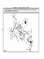
TO INS'i'ALLBLADEGUARDASSEMBLY
• Tighten hex nuts securely.
See Figure 23.
• Lowerthe blade and reinstaflthe throat plate. Tighten
the screws securely.
Proper installationof the blade guard assembly means
that the saw blade and rivingknifeare in alignment.
ALWAYS align the rivingknife to the saw b/ade priorto
turning on the table saw.
• Lower the blade and remove the throat plate.
• Make sure the bevel looldng leveris securelypushed to
the (eft. Raise the saw blade to its full height by turning
the height/bevel adjusting handwheelclockwise.
• Loosen the two hex nuts enoughto slide the riving
knife down between the shims. Do not remove the
he]<nuts. Partially retightenthe hex nuts,Check the
blade and r(vin9knife alignment, _nd mska sure the
rlving knife clears the blade by 1/8 in.
• Align the blade and rivingknife as shown. Blade alignmerit with the rivingknife can be adjusted for diffarard
blade widths. Refer 1o To Cheek, Replace, or Adjust
the Riving Knife and Blade Guard Assembly in the
AdjusO'nentSection, Check the blade guard eseambiy
for clearances and free movemanL
NOTE: If the rivingknife is not positionedcorrectly
lwtth blade up) it could contact the saw table when the
blade is lowered znd rastJ'ictblade elevation.
RIW_
ANTI-KICKBACK
H_N_S
A
41L WARNING: Do not allow familiaritywith tools
to make you careless. Remember that a sarelese
fraction of a second is suf_cfentto inflict severe
injury.
A
i
SHIMS
Fig. 23
APPLICATIONS
You may usethis tool for the purposeslisted below:.
•
Straight line cutting operationssuch as cross cutting,
r_pping,mitering,beveling, and compound cutting
• Dado or molding outs with optional accessories
• Cabinet making and woodworking
NOl'F.: This table saw Jsdesigned to cut wood and wood
compoe_i_nl:_mdu_sonly,
WARNING; Ah_,ayswest safety gogglesor safer7
gbsses with side shieldswhen operatingtools.
Failureto do so could resultin objects being thrown
into your eyes in posaibieserious injury.
BASIC OPERATION OF THE TABLE SAW
_lk
WARNING: Do not usa any attachments or
accessories not recommended by the manufacturer
of'ibis tool. The use of attachments or accessories
not recommended can resultin serious personal
injury.
The 3-prong p[ug must be plugged into a matching outlet that is propertylnst_fled and groundedaccording to
all focal codes and ordinances.Improper connection of
the equipmentcan resultin elec_c shock. Do not modify
the plug if it will not.fit the cuber. Have the correct outlet
inst_led bye qus)ified electrician. Refer to the E}ectric_
section in this manual.
A
WARNING:
Aifhough many of the illustrat;ons in
this manual are shown with the blade guard removed
for clarity, do not operate the saw without the blade
guard unless specifically instxucted to do so.
22
CAUSES OF KICKBACK
CUTTING AIDS
See Figure 24.
Kickback can occur when the blade stalls or binds, kicking the workpieca back toward you with great force and
speed. If your handsare near the saw blade, they may
be jerked loosefrom the workpiece and may contact the
blade. Kickback can cause seriousinjury.Use precautions
to avoidthe risks.
Push sticksare devices used for safelypushing a
workpLscethroughthe blade. They can be made _'orn
scrap wood in various sizes and shapes to be used in
a specific project.The stick must be narrowerthan the
workpieoe,with s g0° notchin one end and shapingfor a
grip on the other end.
A push block has a handle fastened by recessed screws
from the underside. Use it on non-throughcuts.
Kickback can be caused by any action that pinches the
blade in the wood such as:
• Making a cut with incorrect blade depth
• Sawlng into knots or nailsin the workpiece
• Twistingthe wood while makinga out
CAUTION: Be sure the screws in a push blockare
recessedto avoid damagingthe saw or workpiece.
• Failing to supportwork
• Forcing a cut
• Cutting warped orwet lumber
• Us{ng the wrong blade for the type of cut
• Not following oorrect operating procedures
• Misusing the saw
PUStlSTICKS
• Failing to use the an_-kick.baokpawls
• Cutting with a dull, gummed-up, or h'npmperiy set
b_ad_
AVOIDING
KICKBACK
• Always use the correct blade depth setting. The top of
the blade teeth shouldclear the workpiece by 1/8 in. to
114in.
• Inspect the work for knots or nailsbefore beginninga
cut KnocY,out any loose knots w_tha hamme_'.Never
saw into a loose knot or na|(.
Rg. 24
• Always use the rip fence when rip cutting and the miter
gauge when cross cutting.This helps preventtwisting
the wood in the cut.
• Always use cLsan,sharp, and properly-set blades,
Never make outs with dull blades.
• TOavoid pinchingthe blade, supportthe work properly
before beginning a cut,
• When making a cut. usesteady, even pressure. Never
force outs.
• Do not cut wet or warped lumber.
• Always herdyour workplece fLrmtywith both hands or
with push sticks. Keep your body in a balanoed position to be ready to resist kickbackshould it occur.
Never stand direc_y in line with the blade.
• Use the right type of blade for the cut being made.
23
TYPES OF CUTS
See Figure25.
There are six bas;c cuts: 1) the cross cut, 2) the rip cut, 3)
the miter cut, 4} the bevel cross cut, 5) the bevel dp cut,
and 6) the compound (bevel}miter cut. Alt other cuts are
combinationsof these basic six, Operating proceduresfor
making each kind of cut are given later in this section.
_k
WARNING: Always make sure the blade guard
and anti-kickback p_wIs are in place and work'rng
proparty when making these cuts to avoid possible
iniury.
Cross cuts are straight90 ° cuts rr_ds acrossthe grain of
the workpiaos. The wood is fed into the out at a 90 ° angle
to the blade, and the blade is vertical.
RIP CUT
Rip cuts are made with the grain of the wood. To avoid
kickback while making a rip cut, make sure one side of
the wood rides firmly againstthe rip fence.
Miter cuts are made with the wood at any angle to ths
blade other than 90 °. The blade is verticaLMiter cuts
tend to "creep" away from the miter fence during cutting.
This can be controlledby holdingthe workplace astutely
against the miter fence.
_"
MITERCUT
WARNING; Always use a pushstick when cutting
small pieces of wood, and atsoto finishthe cut when
ripping a long narrow piece of wood, to preventyour
hands from ge'_t.ingo{ossto the blade.
Bevel cuts are made with an angled blade. Bevel cross
cuts are across the wood grain,and bevel rip Gutsare with
the grain.The rip fence must always be on the left side of
the blade for bevel rip cuts.
Compound (or bevel} miter cuts are made with an angled
blade on wood that is angled to the blade, Be thoroughly
familiar with making cross cuts, rip cuts, bevel cuts, and
miter cuts beforetrying a compound miter cuL
CUTTING
TIPS
Dado and rabbet cuts are non-throughcutswhich can
be either rip outs or cross cuts. Carefullyread and understand all sections of this operator'smanual before attempting any operation.
A
COMPOUND
(BEVEL)MITERCUT
Fig. 25
WARNING= Do not use btadas rated lessthan the
speed of this tool Fa_urato heed this warning could
result in personal in}ury,
• Cut the wood with the finish side up.
• Knock out any looas knots witf_a hammer before
makingthe cut.
• Always provide proW supportfor the wood as it
comes out of the saw.
• The kerr (the cut made by the blade in the wood) will be
wider than the blade to avoid overheatingor binding.
Make a(iowance for the keff when measuringwood.
• Make sure the kerf is made on the waste side of the
measuring line.
24
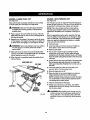
FEATHERBOARD
A fsatherboard is a device used to heJpcontroithe
workpisce by guidingit securelyagainst the table or
fence. Faatharboardsare especially usefulwhen ripping
small workpiecesand for completing non-throughcuts.
The end is angled with a number of short kerfsto give a
friction hold on the workplace and locked in place on the
table with e C-clamp, Test that it can resist kickback.
A
WARNING: Place the featharboard againstthe
uncut portion of the wor_oiece to avoidkickback that
could cause seriouspersonal iniury.
HOW TO MAKE A FEATHERBOARD
See F/gum 26.
The featherboard is an excellent project for the saw.
Select s solid piece of lumber approximately 3/4 in.
thick, 3-5/8 in. wide and 18 in. long. Mark the center of
the width on one end of the stock. Miter one-half of the
width to 30 @and miter the other half of the same end
to 45 ° (see page 32 for information on miter cuts). Mark
the board from the point at 6 in., 8 in., 10 in., and 12 in.
Drill a 3/8 in. hote at the 8 in., 10 in., and 12 in. marks.
HOW TO MOUNT A FEATHERBOARD
See Figure 27.
Remove the adjustingclamp knob, bolt, and washer from
the miter fence holder. Place the boltthrough one of the
holes in the featherboard. Positioningthe fsatherboard
will depend on the placement of the bolt and the position
of the slidingmTtartable on the mils. Placethe washer
on the bolt and attach the adiustingclamp knob, Ioosety.
Pos{tionthe featherboard with the hex head of the bolt
inthemitertableslotbutdo nottighten.
Completely
lower the saw blade. Positionthe rip fence _o the desired
edjusb_ant for the cut to be performed and lock. Place
the workpiece againstthe fence and over the saw blade
area. Adiust the featherbsard to applyresistanceto the
workplace just forward of the blade. Securely tighten the
adjusting clamp knob to secure the featherboardin plane.
Attach a C-clamp to further secure the fsatherboardto
the edge of the slidingmiter table.
_,
Prepare the saw for ripping as discussed on page 31.
Set the rip fence to allow approximately a 1/4 in.
"finger" to be cut in the stock. Feed the stock only to
the mark previously made st 6 in. Turn the saw OFF
and allow the blade to completety stop rotating before
removing the stock. Reset the rip fence and cut spaced
rips into the workpisce 1o allow approximately 1/4 in.
fingers and 1/8 in. spaces between the fingers.
WARN[NG" 0o not locate the featherboa_dto the
rear of the blade. If positionedimproperly,kickback
can result from the featherboard pinchingthe
workpieca and binding the blade inthesaw kerr.
Failureto heed this warning can result in serious
personal iniury.
PUSHBLOCK
FEATHERBOARD
STICK
Fig. 27
3/8 in.
DIAMETER
I
\
-
"-,--;o--,'
3-5/9 in.
I
I
3/4 in.
1OiL
12 is.
18 in,
Fig. 26
25
TOCHANGETHEBLADEDEPTH
See Rgure 28.
The blade depth should be set so that the outer points of
the blade are higherthan the workpisce by approximately
1/8 in. to 1/4 in. but the lowest points (gullets)are below
the top surface.
• Push the bevel locking [everto the left for elevation
mode.
•
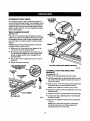
CHECKING SLIDING MITER TABLE AND
MAKING ADJUSTMENTS
TO CHECK MITER BASE PARALLELISM
See Figures 30 - 31.
• Unplug the saw.
•
Raise the blade byturning the height/beveladjusting
hand-whe,s[ ck>ck'wissor !ower it by turning the hendLs
oo_nterdo_k'w_se.
Set saw up as if you were preparing to make a out.
Tighten railclamps, miter lockingclamps, adjusting
clamp, etc.
• Slide miter table CA)to the frontof miter base _) as far
as it will go, Place a reference mark (C) near the end of
the miter _abteas shown in figure30.
NOT_ Front of miter base is on infead s'_e of saw.
QULLL='(
• Place a reference mark on one of the b_ds teeth (D)
and rotsta the blade (1_so that the referencemark on
the blade is at the front of the throat plate.
• Place a framing square (G) againstthe blade and
align
with referencemark on miter fable. Measure the
distance between the blade end the edge of miter
table.
NOTE: Place framing square between carbide teeth
and measure fro_ b_ade.Th_s stepw_ _nsurefTan_ng
squareissquareagainst
bladefromthsfront
to back of
blade,
Fig. 28
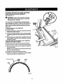
TO CHANGE THE BLADE ANGLE
See Figure 29.
• Push the bevel [ocVdnglever to the right for angle
mode.
• Angle the blade by turning the height/beveladjusting
handwheal until the bevel indicator shows the correct
angle.
• Return the bevel locking lever securelyto the (eft to
lock the angle, whirs holdingthe height/beveladjusting
handwheal in piece.
AN_I.ED
E
A
Fig. 30
INDICATOR
BEVEL
LOCKINGIFVER
0
HEIgHT/BEVEL
ADJUSTING
Fig,.2g
HANDWHEEL
26
3"0 CHECK MITER FENCE ALIGNMENT
See Figure 32,
• Remove framinQ,
square and slide miter table to the
rear o1rafterbase as far as ft w(fl go.
• Rotate the blade so the reference markon the blade is
at the rear of the throat plate. Measuringfrom the s_ms
mark on the blade at the rear wiif eriminatsthe effect of
blade wobble.
The miter fence must be perpendicularto the blade when
set at zero degrees.
•
Set _e miter fanes (H) at 0% M_er indicatoT (I) should
be set preciselyon 0° end securedin place with
adjustingclamp _J).
NOTE" The quick-atopis not necessaryfor this
checking procedure.However, you may want.to check
and adjustit to 0° at this time. See the ToAdjust
Ou_k-Sl_> sent/on thaf fo_ows.
• Plaea a framingsqu_ {G) flnmiya_}_'_sttl_ miter
fence (H), with the other side against the blade (E}.
• Check whetherthe miter fence and blade ate square
with each other. W#.hthe freLrn{n
9 squme age{net the
miter fence there shouldbe no gap from the front to
the rear of the blade,
• Place framing square againstthe blade and align with
the same reference marY:on the mitsr table. Measure
the distance between the blade and the edge of the
miter table at the rear.
• Compare whether the front and rear measurementsare
the same. It they are the same, proceed with shecking
ths miter fence alignment, If not, this inc{icatasthe
miter base needs afign(ng. Mi!sr base musl then be
adjustedbmforecheckingmiterfencealig_'nent.
S_e
To Adjust The Miter Base sectionthat follows,
I]
E
•
•
\
H a gap exists, the miter fence may be out of square.
Rotate the blade and recheck.If there is a consistent
gap between the front and rear of the blade, the miter
table needs a|ignlng.Followthe adjustment procedures
that follow.
F
I
B
Fig. 31
Fig. 32
27
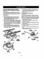
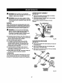
TO ADJUST THE MITER BASE
See Figure 33.
Remember: Check all settings before looseningscrews
for the foflowfng procedures.Once screws have bean
toosened, these settingsmust be reset.
Eight screws ere visible on the miter base (B).
MITERTABLE
• Four screws (k")o_eon the holderplates and secure
these plates to the rails. It is not necessaryto loosen or
adjust these screws for this adjustment procedure.
• Another pair of screws (L)is in the base, at the rear.
Loosen these two screws(I-) end the rear miter (ocking
o[amps (M).
• The last paZrof screws is located on the infesdside of
the base. Loosen the left screw (N) only,
SLIDES
• The right screw (O) will be used as a pivot point.
NOTE: The fTonttWOmiter locking c(amps (P) and rail
clarnps shouldrem_n locked.
• Adjust the miter base so that it is parallelto the blade
see To Check Miter Base Parsltellm'n.
• Retighten the [eft fi'ont screw (N).
• Clamp the rear miter Locking clamps (M).
Fig. 34
• Retighten the two rear screws (L).
TO ADJUST THE MITER FENCE
See F_Jras 34 - 35.
M
L
II Set the miter fence (H) at 0°. Miter indicatorshould be
set preciselyon 0° and secured in place with adjusting
cl_¢np(J).
• Ther_ are four slideslocated under the s_dingmiter
ta,ble. These slideslet the miter table move on the
base. Three slidesare mounted on eccentricscrews
that can be adjusted by looseningthe hex nuts on top
of the miter table.,
M
•
Loosen the rear hex nuts (Q) on top of slidingmiter
table for this adjustment procadure.
NOTE: The front screws (R)are onty needed to remove
excessive play in the slides due to wear from extended
use. They are not neededfor this procedure.The right
front hex nut is a non-eocantricpivot and should never
be ;oasened.
K
• Adjust the right rear eccantrJcscrew from the lower
side of the miter table so that maximum play exists
betweenthes_ideand m'ftarbase.
K
•
Fig. 33
Push left rear of miter table snugly against miter base
as shown by the arrow (S) in figure 35 and secure,
• P_ca a fi_'nlng square firmlyagainst the miter fence,
with the other ,ride againstthe blade.
• Adjust left rear screw from undern_th miter table until
miter fence end brads are square with each other,
28
• Tightenhex nut securely.
• Adjust rightrear screw from underneath miter table to
remove excessiveplay.
TO ADJUST QUICK STOP
See Figure 38.
The quick stop is preset at the factory to stop the miter
fence at sxactiy zero degrees. However,when sliding
miter table adjustmentsare made, these adiustmentsmay
cause the quick stop to need adiusting.Check qu(ck stop
with miter scale set at zero degrees. If adjustmentsare
needed, proceed with the followingsteps:
• Tighten hex nut securely.
•
Recheck your setups carefully.Alse make sure a[[
screws, hex nu_s,etc., h_ve been tightened securely.
• If sliding miter table assembly is still not square with
the blade, repeat the above proceduresas needed.
•
Make sure that sfidss remainsquareto miter base
edo,e to preve_ =oookir=_=which will resultin excessive
play in miter table.
•
Loosenthe eccentric screw holding the quick stop.
•
Piecethe quick stop againstthe miter fence with miter
scale set at zero degrees.
• Adjusteccentricscrew untilit holds quick stop securely
a_]aJnstmiter fence.
• Rstk..lhtenhe);nut, secur{ngeccentric screw and q,qck
stop.
• Check yourwork. If the quickstop is not at zero
degrees, repeat above steps.
t
Q
QUICK
STOP
Fig. 35
Fig. 36
29
&
RiP
WARNING: "1"o
reduce the r_k of injury, always
make sure the rip fence is parallel to the b_ade before
b_innfng any opar_t'_o_.
TO SET THE RIP FENCE SCALE INDICATOR
THE BLADE
See Figure 37.
BLADE
FENCE
SCALE
TO
Use the following steps to set the rip fence scale indicator
to the blade. Begin with the blade at a zero angle (sVaight
up).
• Unplugthesaw.
• Loosen the rip fence by depressing the lock and lifting
the rooking handle.
• Using s framing square, set the rip fence 2 in. from the
bride tipedge.
• Loosen the screw on the scale indicator.
• Tighten the screw and check the dimension and the rip
fence.
E
LOCKING
LEVER
INDICATOR
2 in.
MARl(
TO USE THE RIP FENCE
Figure 38.
• Place the mar lip on the rear of the saw table and pull
slighttytoward the front of the unit.
• Lower the front end of the rip fence onto the guide
surfaces on top ofthe front rail.
• Push the rip fence lever down to automaticaflyalign and
secure the fence.
RA]L
Fig. 37
LOCKING
LEVER
RiP FENCE
SAW
Cheek for a smooth glidingaction. If adjustmentsare
needed, see To Check the Alignment of the Rip Fence
to the Blade in the Adjusfrnenfsection of this manual.
TO USE THE MITER GAUGE
See F=Jgure
39.
The miter gauge providesgreater accuracy in angHd cuts.
For very close tolerances, test cuts are recommended.
Them are two miter gauge channels, one on either side
of the blade. When maldng a 90 ° cross cut, you can use
either miter gauge channel. When making a beveled cross
cut (the blade tilted in relationto the table) the miter gauge
sheutd be located in the slot on the right so that the blade
is tilted away from the miter gauge and your hands.
RE_ L|P
Fig. 38
The miter gauge can be turned 60 ° to the right or left.
• Loosen the lock knob.
LOCK
• With the miter gauge in the miter gauge slot, rotate the
gauge until the desired angte is reached on the scale.
•
Retighten the lock knob.
MITER
GAUGE
Fig. 39
MAKINGCUTS
Thebladeprovided
withthe saw is a high-quality
combination blade sultabTefor ripping and crossout operations.
SV//T_H
_1, WARNING: Do not use blades rated less than the
speed of this tool. FaiKureto heed this warningcould
resultin perscnal injury.
SWITCH
ON
\
Use the miter gauge when making cross, miter,bevel,
and compound miter cuts. To secure the angle, lock the
miter gauge in place by twisting the lock knob clockwise.
Always tighten the lock knobsecurely in pJaoebefore use.
NOTE=It is recommended that you place the piece to be
saved on the left side of the blade and that you make a
test cut on scrap wood first.
°?
SWITCHKEY
MAKING A CROSS CUT
See Figures40 - 41.
WARNING: Using the rip fence as a cutoff gauge
when crosscuttingwit1resultin kickback which can
cause seriouspersonat injury.
WARNING=: Make sure the blade guard assembly
is installed and working properly to avoid serious
possible injury.
'8WITCHIN LOCI_DPOSITION
Rg. 41
It is recommended you make test cuts on scrap wood.
•
Remove the rip fence by liftingthe lockinghandle.
•
• Set the blade to the correct depth for the workpiece.
• Set the miter fence to 0 ° and tighten the lock knob.
Place a support (the same height as saw table) behind
the saw for the cut work.
• Make sure the wood is clear of the blade beforeturning
on the saw.
CROSSCUT
• To turn the saw ON, lift the switch button.
PLACELEFTHANDON
WORKPIECE
AND
MITERFENCE
HERE
• To turn saw OFF, press the switch button down.
NOTE: To prevent unauthorizeduse, remove the switch
key as shown in figure 41.
• Let the blade build up to fullspeed before movingthe
wot_piece _ntothe b_ade.
•
•
Hold the workpieca firmlywith both hands on the miter
gauge and feed the workpiece into the blade.
When the cut_ made, turn the saw off. Wait for the
blade to come to a complete Hop betore removing the
workpiese.
MAKING A RiP CUT
See Figure 42.
It is recommendedyou make a test cut on scrap wood.
Fig. 40
31
,_
WARNING: Make sure the blade guard assembly
is installedand working proper(y to avoid serious
possibleinjLIry.
•
Positionthe rip fence the desired distance from the
blade for the out and sasurstylook the handle. Adjust
the scale to zero at the cutting edge of the blade.
• P_ace
a support/,the
sameheight as saw tablel behind
MAKING A MITER CUT
See F-agure
43.
It is recommendedyou rnske test outs on scrap wood.
the .saw for the cut work.
•
Make sure the wood is clear of the blade before turning
on ti'_e ,_Lw.
• Use a push block or push stick to move the wood
through the out past the bla_de.Never push a emafl
piece of wood into the blade with your hand, always
use a push stick. The use of push blocks, push sticks,
and feathathoards are necessarywhen ma_rngnonthrough cuts.
• Stand to the side of the wood as it contacts the blade
to reduce the chance of injuryshould kickback occur.
Never stand directly in the line of cut.
• Make sure thewood iss[ear of the blade beforeturning
on the saw.
• Let the blade b_Jildup to full speed before feeding the
workplece into the blade.
• When the cut is made, turn the saw off. Wait for the
bladeto come to a completestop before reme_ng the
wo_pieoe.
_k
WARNING: Make sure the blade guard assembly
is installedand working pmper]y to avoid serious
poes_is injury.
• Remove the rip fence by liftingthe locking handle.
• Set the miter gauge to the desired angle and tightsn
the lock knob.
• Place a support(the same height as saw table) bah'rod
the saw for the cut work.
• Make sure the wood is clear 0f the blade before turning
on the saw.
• Let the blade bugd up to full speed before moving the
work,piece intotheb_ade.
• Feed the work:pieceintothe blade until the out has
been completed.
MITERCUT
RiP CUT
BLADE
RiP
FENCE
MITERGAUGE
ANGLED
HEIGHT
AOJUSTING
HANDWHEB.
Fig. 43
MAKING A BEVEL CROSS CUT
See Ffeures44 - 45.
It is recommendedthat you place the piece to be saved
on the leftside of the bladeand that you make s test cut
on scrap wood.
X
WARNING: Make sure the blade guard assambly
is instsJlsdand workingpmpedy to avoid serious
pose'lois_n)ury.
• Untookthe bevel Iocking 1ever.
• Remove the rip fence by liftingthe [o,_kinghandle.
• Turn the height adjustinghandwhesl until the bevel
indicator is at the desiredangle. Push the beve(
lockinglever securelyto the left to lock the angle.
• Set the blade to the correctdepth for the workpiece.
32
VIEWEDFROMTHEFRONT,BELOWTHETABLESAW
MAKING A BEVEL RIP CUT
See Rgure 48.
It is recommended you make test cuts on scrap wood.
A
A
TO
TIGHTEN
WARNING: The rip f_ce must be on the left side
of the blade to avoid _apping the wood and causing
kiokback. Plaoementof the tip fence to the right
of the blade will resultin k_ckbackarid the risk of
_fiouspersonal
injury.
_1_ WARNING: Make sure the blade guard assembly
is installedand workingproperly to avoidserious
persona{injury.
• Remove the sliding miter table and move the accessory
table to the left side.
BEVEL ,
LOCKING
LEVER
• Adjust the bevel angte to the desired setting.
• Set the blade to the correct depth.
•
TOLOOSEN
Rg. 44
•
Set the miter gauge to g0° and press the bevel Iocldng
tevar towards the tabte to Iosk.
•
Place a support (the same height as saw table) behind
the saw for the cut work.
•
Make sure the wood is olaar of the blade beforeturning
on the sew.
•
Let the saw blade build up to fullspeed before moving
the miter gauge and the workplace into the blade.
• Hold the workplace firmlywith both hands on the miter
gauge and feed the workpieoe intothe blade.
• When the cut _smade, turn the saw off. Wait for the
blade to corns to a complata stop before rsmov_ngAs
workpisce.
BEVELCROSSCUT
BLADE
ANGLED
MITERGAUGE
STRAIGHT
LEVER
Positionthe r_pfence the desired distance from the left
side of the blade and lock down the handle.
• If rippinga piece larger than 36 in. long, place a
supportthe same height as the _.ble surfacebehind
the saw for the cut work.
• Turnthe power switch to the ON position.
•
Positionthe workpisce fiat on the tabis with the edge
flush against therip fence. Let the bisde buii_ up to full
speed before feeding the workplace into the blade.
• Using a push stick and/or push blocks, slowlyfeed
the workplace toward the bb.de. Stand slightlyto the
sl_e of the wood as it contacts the blade to reduce the
chance of injury shouldkickt_k occur.
• Once the blade has made contact with the workplace,
use the hand closest to the rip fence to guide it. Make
sure the edge of the workplace remains in solid contact
with both the rip fence and the surface of the table. If
rippinga narrow piece, use a push stickto movethe
piece through the cut and past the blade.
= When the out la made, turn the saw off. Wait for the
blade to come to a complete stop before removingthe
workplace.
• After the blade has stopped oomplateiy, remove the
cutoff stock.
• Loosen the lock knob on the miter gauge, set the miter
gaugeto the desired angle and tighten lock knob.
• Turnthe power switch to the ON position.
• Positionthe workpiece fiat on the table with the edge
flushagainst the miter gauge. Let the blade build up to
full speed before feeding the workplace Into the blade.
• Grasp the workplece from the lead end (the and fed
into the b{ade first) and carefully remove it from the
table.
• Advance the workplace and the miter gauge toward
the blade. Keep the workpiece flushagainst the miter
gauge. Push the miter gauge and workplace toward
the blade. Stand slightlyto the side of the wood as
it contacts the blade to reduos the chance of injury
should kickback occur.
BEVEL.
RiP CUT
8LADE
ANGLED
II When the out Is made, turn the saw off. Wait for the
blade to come to a complete stop beforeremovingthe
workplace.
SCALE
\
• After the blade has stopped completely,remove the
cutoff stock.
COMPOUND
(BEVEL)MITERCUT
PL_ RIGHTHAND
ONWORKPIECE
AND
MR'ERGAUGEHERE
Fig. 46
MAKING A COMPOUND
See Figure 47.
(BEVEL) MITER CUT
It is recommended that you place the piece to be saved
on the left side of the blade and that you make a test cut
on scrap wood firsL
_1, WARNING: Make sure the blade guard ass_"nbly
is installedand working propedy to avoid sadoue
posaibla
injury.
•
•
Remove the rip fence by liftingthe lock down handle,
Unlock:he bevel locking lever.
• Adjust the bevel angle to the desired setting.
• Lock the bevel locking lever.
•
Set the saw blade to the correct depth.
34
MAKING A LARGE PANEL CUT
See Figure48.
Make sure the sew is properly securedto e work surface
to avoidtipping from the weight of a large panel
MAKING A NON-THROUGH
See Figure4g.
CUT
_,
NOTE: TtT_sis the onlytype out that is made without
the blade guard instsIled.Make sure the blade guard
assembly la reinstalledupon completion of this type of
cut.
Non-through cuts can be made with the grain (ripping)or
across the grain (crosscut}.The use of a nOn-throughcut
is essentialto cutting
grooves,rabbets, and d,ad.oes.
WARNING: Make sure the b_ade guard assembly
is installedand working properly to avoidserious
pessibteinjury.
• Place a supportthe same height as the top of the saw
table behind the saw for the cut work. Add supportsto
the sides as needed.
Read the appropriate sectionwhich describesthe type
of cut inaddition to this section on non-throughor dado
cuts. For example, if yournon-throughcut is a straight
cross cut, read and understandthe sectionon straight
cross cuts before procaed{ng.
• Unplug the saw.
• Depending on the shape of the pansl, use the rip fence
or miteTgauge, ff the panel is too large to use s_'herthe
rip {once or the miter gauge, it is too {argofor this saw.
_IL WARNING: Nsvsr make freehand cuts {cutswithout
the miter gauge or rip fence), which can resultin
seriousinjury.
• Lower the blade and removethe screw holdingthe
throat plate in place. Remove the throat plate.
• RaLsethe saw blade.
• Make sure thewood does not touch the blade before
you turn on the saw, Let the blade bu_d up to full speed
beforefoeding the wood _,ntothe blade.
• Put the sew in angle mode by pushingthe bevel
locking lavar to the right. Turnthe height adjusting
hsndwheel until the b(ade indicster showsa 30" ar_jis.
Push the bevel locking{eversecurelyto the [eft to lock
the angle,
• When the work is oemplstod, press the switch offand
remove the key.
• Loosen the two hex nuts st the base of the riving knife.
Do not remove hex nuts. Removethe rivingknife/
blade guard assembly.Retightanthe two hex nuts on
the base,
lARGEPN(EL CUT
RIP FENCE
• Lower the blade and insert the throat plate, then
securelytighten the throat plate screw.
• Bring the blade backto gO°.
• Raise the blade _o the correcthaigh'tby tuTningthe
height ad{ustinghandwheelcounterclockwise.
NOTE: Carefullycheckall setups and rctsta the blade
one fur{revolutionto assure properclearance before
connecting saw to power source.
• Feed the workpiscs into the blade.
• Always use push blocks, push sticks,and featherboards when makingnon-throughcuts to avoid the
risk of seriousinjury,
HEIGHT
ADJUSTING
HANDWHEEL
_1= WARNING: When making a non-through cut, the
cutter is covered by the warY,piece during most ot
the cut. Be alert to the exposed cutter at the start
and finishof everycut to avoid the risk of personal
injury.
Fig. _-8
35
,_
MAKING A DADO CUT
WARNING: Never feed wood with your handswhen
ma_dngany non-throughcut such as rabbets or
dadoes. To avoid personal injury, aJways use push
blocks, push sticks, and featherboards.
See _gurs 50.
• When the cut is made, turn the saw OFF. Wait for the
blade to come to a complete stop before removingthe
workpieca.
An optior_l _Ladothroat plate _sreq_drsdfor this procadurs (max. dado wirtth _3/16 in.). See the Accessorles
sectionof this manua! and check with your nearest Sears
retsil. Do not use blades rated less than the speed of this
tooL
NOTE: This saw cannot be used to make a bevel dado
CUt.
• Unplug the saw.
• Lower the blade and remove the screw holding the
throat plate in place. Remove the throat plate.
• Raise the saw b(ade.
• Push the bevei lockingleveeto the right.Rotate the height
adjustinghandwheelunUithe bevelindicatorshowsa 30+
angle. Push the bevel Iocldng leveesecurelyto the left
while holdingthe height adjustinghandwheelto lock the
angle. Reinsta_the b_adeguard assembly.
• Retighten the nuts at the base of the riving knife.Check
riving kni_'ealignment to the blade and adjust shims if
necessary.
• Move the bevel locking [everto the right and rotate the
blade back to 90% Push the leverto the left to lock the
angle.
• Lower the blade, insert the throat plate, then securely
tighten the throat plate screw.
• Unplug the saw.
• Remove the blade guard aseembly.
• Ratlghtanthe two hex nuts.
• Remove the saw blade.
• Remove _he inner blade washer and both the sma_ and
_eegespacers.
• Add the smell spacer then the inner b]ade washer to
the bladesarbor.
• Mount the dado blade, usingthe blade and chippers
appropriatefor the desired width of cut.
• Reinstallthe arbor nut.
• Make sure the arbor nut Is fullyengaged and the
eebor extends at loast one fiJll_rsad past a sacurely
tightened arbornut.
_k
WARNING; Always put all spacers in proper
locationwhen changingback to saw blade. Failure
to do so may resultin possible injuryand damage to
the tool.
A
WARNING: Akvays use push blocks, push stlc_, or
fsatharbcardswhen making dado cuts to avoid the
risk of serious injury.
NON-THROUGHCUT
GUARD
BLADE
REMOVED
9J_l}0CUT
PUSH
STICK
Fig. 4g
F_g.50
• 36
T-NUTBETWEEN
ADJUSTMENT
SCREWS
ACCESSORY TABLE USAGE
Th|s accessory table has been spec'dtcaltydesignedfor
use with listed Craftsmen Routars.The hole pattern on the
accessory table has notbeen drfflad to accommodate all
reuters. Reuters must not exceed 3 HP (maximum developed) or weigh more than 12-1/2 Ibs. Reutersmust have
took-on switch feature.
TABLE CLAMP|NG
See Figure 51.
BRACKET
REAR
ADJUSTMENT
SCREW
The lever on the accessory table wilt.tighten the table securelyto the front rail. The weight of the muter may cause
the accessory table to loosen or have movement st the
rear of the table. To avoid this, install the table clamping
bracket.
NOTE: Positionthe table clampingbracket so that the
accessory table is centeredover it.
II Slide one of the T-nuts into the front channel of the
rear rail and under the aooeseorytable.
• The table clamping bracket fits in the bottom slot of
the rear railand the slotted top of the bracket wraps
around the raised portion on the undersideof the
accessory table.
• Secure wlth a 5/16 in. washer and a 5/16-18 x 3/4 in.
knob bolt.
•
Tighten the knob bolt securely.
TABLECLAMPINGBRACKET
SHOWNCOMPLETELY
ASSEMBLED
__,._
ACCESSORY
T.,E
RIP FENCE
SHOWNLOCKED
AGAINSTSAWBLADE
_
Fig, 52
TO INSTALL T-NU'£_ FOR GUIDE FENCE
BRACKETS
See Figures52.53.
• Place rip fence against blade and lock in place,
L L_L)_
TABLECLAMPING
BRACKET
• Usingthe appropriate hex key supplied with your table
saw, remove the rear adjustment screw and washer on
top of the rip fence.
• Slide one of the T-nutsintothe top channel of ripfence
and place between the two adjustment screws.
T-NUT
END
CAP
NOTE: T-nutsinstallfrom the rear of the rip fence.
• Replacethe washer and the rear adjustmentscrew and
tighten securely.
_/'16in.WASHER
• Checkthe rip fsncs for squarsnesswith ths saw blade,
• Unlock the rip fence, slide it away from the saw blade,
and lock it in place,
KNOBBOLT
Fig. 51
Slidethe four remainingT-nuts into the top channelof
ripfence.
NOTE: Five T-nuts shouldbe in the top channelof
the rip fencewith only one of them between the
adjustmentscrews on the rip fence.
37
INSTALL
T-NUTS
FROM
REAR
OFRIPFENCE
T-NUT
TO INSTALL POST, GUARD/DUST
PIVOT ASSEMBLY
See F/gum 54.
COVER WITH
The guard/dust cover must be used in all routing operations.
• Place the spacer on the threaded end of the post and
thread the post into the remaining"i-nut.
• Tightsn the post securelywith an ad.iustab|ewrench on
the fiats on the top of the post.
•
Plane the guard/dust cover with pivot assembly on the
pesL
• "Theassemblywill slide up and down on the post as
needed. Scours at the desired location by tightening
the knob nut attached to the carriagebolt.
GUARD)DUST
COVERWITH
P|VO_ASEMBLY
Fig.53
TO INSTALLGUIDEFENCEBRACKETS
CARRIAGE
BOLT
KNOB
See F/gum 54.
• To install the guide fence brackets, align each bracket
with two of the T-nuts on top of the rip fence.
FLAT8ON
NOTE=Usa the hnt two T-nuts and the back two
T-nuts leaving the one in the middle empty.
•
KNOB
BOLTS
Secure the guide fence brackets to the rip fence with
5/16 in. washers and the 5/16 in. x 1/2 in. knob bolts.
5/tll i.
WASHERS
GUIDE FENCE
BRACKET
SPACER
T-NUTS
RIP FENCE
Fig. 54.
38
TOINSTALLROUTER
• Select the correct
size throat plate for the size of the
router bit. Align the tab on the throat platewith the slot
in the muter extension and snap in place. Make sure
the throat plate is firmly seated below the _able surface.
Recheck the router bit to make sure it will not s_ke the
throat plate.
FINAL PREPARATION FOR OPERATION
See Figure 56.
See Ftgure55.
• Unptugthe router.
• Place your router upside down on a workbench.
• Remove the subbase screws and the subbasefrom
your router.
NOTE: The subbase is mounted permanentlyon some
routere and should not be removed.
•
• Adjust the guard/dustcover so that it will not corns in
conta_ with the workplace or cutter duringa cutting
operation.
Select the screws needed for yourparticular router.For
consumer reuters, use the 10-32 x 3/4 in. screws.For
eommerc'la_Pouters,use the 5/16-18 screws.
• D[rectionof feed of the workplace is from right to left or
from the back of t'nesaw toward the frontwith the bit
located in the fence opening.
• Positionrouter upside down under the router extension
tabie. The router label should be facingthe front of the
table.
• Atign the holes in the table with the holes in yourrouter.
Feed the screws through the table and intothe router.
• Tighten all screws with a screwdriver.
\
Fig. 56
• Directionof feed mustalw,_ysbe so thatthe workpiece is
being thrust againstthe sharp edges of the foraying bit.
i
• The workp'lecemust alwaysbe tight against _e guide
fence, unlessa ba_-bearing pilotedbit is being used.
The Infeed fence shouldbe adjusted to support the
uncutworkpiees whi_ethe outfeed fence should be adjusted properlyto supportthe workpisce after the cut
passes the router bit, compensatingfor the removed
stock.
Rg. 55
41_ WARNING: The directionof feed for the workpiece
is always againstthe sharp edges of the bit and
againstthe rotationof the cutter.Fai(uroto heed this
warning is I_ely to resultin sedous personalinjury.
TO INSTALL BIT AND THROAT PLATE
The router throat plates are included to assure no more
than1/4 in. eisarance between the cutter and the opening
in the throat plate. Use the correct throat plate.Do not use
a router bit smaller than I/4 in, or larger than 2 in.
_i,
• To installthe router bit, fotlow the instructionsin the
operator'smanua_that came with yourrouter.
_"
CAIN:
Make sure the router bit will not strike
the accessory table or any metal surface.
3g
WARNING: Do not use the guide fencewith ball-bearing pilotedbits. Failureto heed this warning
may TesuRin serious peTsonalinjury.
A
A
WARNING." Before performing any adjustment,
make sure the tool is unplugged from the power
suppty. Failureto heed this waTn'lngcoutdresu)tin
serious persona_injury.
WARNING:
Blades coast after turn off. Possib}e
serious injury can occur if hands come in contact
with blade.
The table sew has been adjusted at the factory for makingvery accurate cuts. However, some of the components
might have been jarred out of alignmentduringshipping.
ALso,over a period of t'rne, rsediustmentwill probably
become necessary
due to wear.
BLADE
NUT
3"0avoid unnecessary setups and adjustmen*.s,a good
practice is to check your setups carefullywith a framing square and make practice cuts in scrap wood before
making finish cuts in good workpiaces. Do not start any
adjustments until you have checked with a square and
made test cuts to be sure adjustments are needed.
Fig. 58
TO REPLACE THE BLADE
See Figures57 - 59.
To replace the blade with an accessory blade, follow the
instructionsprov'_ed with the accessory.
To Inatall e standard blade:
• Place thenew blade on the arbor shaft (the teeth
must point down toward the fi'ontof the saw to work
properly),
• Place the blade washer and the blade nut over the
blade arbor.Be sure the dome side of the blade
washer f_cas ou_.from _a blade and that all items ere
snugagainst the arbor housing,13ghtensecurely.
• Rotate the blade by hand to make sure it turnsfreely.
• Reinstallthe throat plate.
NOTE: Seaurelytighten throat plate screws. Do not allow the throat plate to bow up above the table surface.
• Unplug the saw.
• Lowerthe saw blade, raise the blade guard, and
remove the throet plate.
• Make sure the bevel lockinglever is securelypushed to
the felt. Raise the sew bladeto its full height by turning
the haight/beve_ adjusting handwheelclockwise.
• Using the smallblade wrench, insertthe flat open and
into the fiats on the arbor shaft.
•
Insertthe closed and of the largeblade wrench over the
hax nut. Holding bo_.hwrenches li_nly, pull_.h_larger
wrench forward to the f1"ontof the machine. Make sure
the blade nut is securelytightened. De not overtighten.
NOTE: Arbor shaft hasleft hand threads.
Check allcrearancesfor free blade rotation. See To Set
the Scale to the Blade in this section. In cutting operations, the scarewilt be set to the side of the blade where
the cut will be measured and made.
BLADE
THROATPLATE
THROM
PLATE
RMNG
KNIFE
BLAI)E
LARGE
BLADE
WRENCH
SMALL
BLADE
WRENCH
©
Fig. 59
Fig. 57
40
TO CHECK,REPLACE,
ORADJUSTTHERIVING
KNIFEANDBLADEGUARDASSEMBLY
See Figures 60 - 61.
A
AlL WARNING: Propertyalign riving knits. |mproperiy
atigned rivingknife may cause blade to btndwhich
will increaserisk of kickback.
The rivingknife is mounted between several shims that
can be relocated as needed to center the knife behind the
blade. It is held in place by two bolts and hex nutsat its
base. The bolts are set in slots that permit front-to-back
adjusb'nent.
FRAMING
SQUARE
"Tocheck a_gnment of the _vin 9 knife:
• Unplug the saw.
• Raisethe saw blade byturningthe height/beveladiuating
har_twheel¢ountsml_ckwisa.
• Lift the anti-kickback pawls and place a framing square
or s'_mightedge againstboththe saw bladeand the riving
knife.
• The saw blade and riving knife are aligned when the
framing square contacts both the biade and rh/ingknife
eventy with no gaps.
If the dvthg knife and saw blade am not In alignment,
adjustment is needed. To adjust:.
• Unplug the saw and raise the b_adeguard assambly.
• Remove the throat plate and the blade guard assembly.
• Move the shims to bring the riving knife into alignment
with the saw blade.
Fig. 61
NOTE"It may be necessaryto removethe shimsand turn
them in an opposite direction.
•
•
Ralnstaflthe rivingknife between the shims.
Recheck the atignment by placing the framing square
beside the saw blade as explained above.
RIVING
KNIFE
BLADE
1/8 in.
R_. 60
41
TO SET THE B_VEL INDICATOR AND BEVEL
STOPS AT 0_ AND 45 ° (SQUARING THE BLADE)
Figure 62.
•
If the blade is not an exact 45 °, loosenthe lock nut
on the 45° bolt inside the cabinet, positionthe blade,
adjust the bolt, then retighten lock nut.
• Make a test cut.
The angle sa_mgs oFthe saw have been set at the _actory and, unlessdamaged in shipping, should not require
setting during assembly. After extensive use, it may need
to be checked.
TO ADJUST THE MITER GAUGE
See Figure 63.
• Unplug the saw.
• Push the bevel looking lever to the right.Turn the
t_eight/beve{ adjusting handwhsel to angle L'heblade.
Use • combinationsquare to check squareness
between the blade and saw table.
NOTE The miter gauge providesclose accuracy in angled
cuts. Forvery close tolerances,test cutsare recommended.
You can set the miter gauge at O° and plus or minus 45°
with the miter gauge stop pin and adjustablestop screws.
•
•
If the blade is not perfectly vertical (0_),loosen the lock
nut on the 0° bolt _nside the cabinet, positionthe blade,
adjust the bolt, then retighten lock nut. See Figure 62,
insall, if the banal indicator is not at zero, adjust_tw_.h
the "twoscrews above the slot, beside the heighVbevel
adjusting handwheel.
• Turn the heighVbevel adjusting ha.ndwhesluntilthe
bottom of the blade has moved completelyto the left
side of the slot. Lock the angle by pushing the bevel
_ocking lever to the left.
•
Loosen knob and pull out on stop pin to rotate miter
gauge base paststop screws.
Loosenthe lock n_t of the 0 ° stop screw st the stop
pinwith a 8 rnm wrench.
• Place a 90" squareagainstthe m_ar gauge rod and the
miter gauge base.
•
If the rod is not square, loosenthe knob, adjust the rod,
and tighten the knob.
• Adjust the 0 ° atop screw until it restsagainst the stop
pin.
• Adjust the plus end minus 45° stop screws usinga 45 °
triangle and the stepsabove.
MITER
GAUGEBASE
m
MITER_
GAUGEROD
LOCK/
NUT
BEVEL
LOCKINGLEVEE[
O"ADJUSTABLE
STOPSCREW
45"ADJUSTABLE
STOPSCREW
HEIGHT
ADJUSTING
HANDWHEEL
Fig. 63
BOLT
O"BOLT
LOCK
NUT
BEVEL
INDICATOR
Fig. 62
42
TO CHECKTHEALIGNMENTOFTHERIPFENCE
TOTHEBLADE
SeeFigure 64.
•
UnpLugthe saw.
•
Raise the (ooking handle to permitthe rip fence to be
moved.
TO ADJUST THE BEVEL LOCKING LEVER
See FTgura65.
"Fhebevel looking levermay work loose and require
adjusting. To adjust:
• Unplug the saw.
• Push the lever full left to the fecked position.
• Remove the screw on t_e heighS_bevel
adjusting
handwhaeLYouwritneed the 3/16 in, hex key for this
procedure.
• Remove the height/bevel adjusting handwhseland
cam. Pullout the cam.
• Remove the set screw on the bevel lockinglever.
• Remove the bevel lockinglever from hex nut,
II Relocate bevel locking lever on the hsx nut.
• Replace set screw and tighten securely.
• Replace the cam so that the lobe is againstthe tab.
Make sure the cam is seated in the lever.
• Reaseemb)sthe height/bevel adjusting handwheelto
the shaft and cam. Checkwhether the lever is now in
the desired position.Tightenscrew securely.
BLADE
HEIGHT/BEVEL
ADJUSTING
HANOWHEEL
SOCKET
H_DS_EW
SCREWS
SETSCREW
LOCKING
HANDLE
•
Fig. 64
Place a framing square beside the blade and move the
rLpfence up to the square. Take the dimensionon the
rip scale.
HEXNUT
• Move the fence back and turn the framing square180 °
to check the other aide.
CAM
• If the two dimensionsare not the same, loosenthe two
s_'ewa on _s fence end align it.
• Retightenthe two screws.
COMPRESSION
SPRING
HANDWHEEL
ADAPTER
• Make two or three test cuts on scrap wood. it the cuts
are not true, repeat the process.
NOTE: The rip fence must be secure when the locking
handle is engaged. The clamp screwon the rear of the rip
fence istightened by turning clockwiseto increasetightnessof the rear of the rip fence.
, BEVEL
LOCKING
LEVER
Fig. 65
43
TOAUGNTHEMITERLOCKINGCLAMPS
RAILHOLOER
NUT
See Figure 66.
The miter locking clamps are preset at the factory but may
requireadjustingafter extended use or if damage occursin
shipping.
RAIL
CLAMP
• Unplug the saw.
• Loosen the set screw behind each lockingclamp.
WASHER
• Loosen the screw on top of each Iockingclamp.
• Uft the locldng clamp to the up position,
•
Push the clamp forward tight against the front railto
bringthe c_p into aiigr_'_ent.
• When the clamps are correctlypositioned, retightenthe
scows and the set screws.
HE)(MOUNTING
BOLT
• Push both front and rear miter lockingclamps down to
secure the s|idingmiter table.
Fig. 67
SCREW
TO ADJUST THE ACCESSORY
See Rgure 68.
TABLE
After extended use, the acce..-_, tab/e may work loose
caus(_ th_ accessory table to be {oos_ o_ the ra'_s.
Foi(ow the steps below, when adjustmentsare required:
•
•
Unplug the saw.
Remove the hex nut on the lever using s 3/8 in. nut
driver.
•
Remove t_e backup p{ateand spring plate. Rotate the
springplate 180° and reinstallon the handle shaft.
• Reassemble all parts end tighten hex nut securely.
NOTE; The spring plate offers two ends for use before
re_[uiringreplacement.
ACCESSORY
TABLE
Fig. 66
LEVER
TO ADJUST THE FRONT AND REAR RAIL
CLAMPS
See Rgure 67.
The rail cramps ate located below the raUsand ensure tight
attachment of the rail. Followrngextended use, the rail
holder nut inside the rails may need adjusting.
• Unplug the saw.
HAl
_"IAFT
• Remove the miter table and accessory tabla.
• Remove the _ont emdrear rails by looseningthe rail
crampsand dlding the rai_soff.
BACKUP
PLATE
• Rotate each rail clamp to the {sft unti{it hits or comes in
correct with the bo'_om ot the saw table.
RING
SPRINGPLATE
HEXNUT
F_.68
• Tighten rait holder nut until it is snug.
• Loosen rail holder nut one-fourth (1/4) turn.
• Replace the rails and check the rail clamps.
44
A
Am, WARNING: When servicing, use only identice_
repianementpaps. Use of any other parts m_y create
a hazardorcause product damage.
A
Am. WARNING: A_vays wear safety goggles or safety
glasses with side shietdsduringpower too_opera,on
or when blowing dust. If operation is dusty,also wear
a dust mask.
LOCKER BRACKET ASSEMBLY
See Figure69.
• Add dry lube between both bevel gears, theb_ckup
washers,and the locker braoket..
• Adddrylubs be_:weenthreaded hole in motor casting
and threaded elevatingshaft.
Recommended Lubricants:Dry Siliconeor Tenon
Lubricant
GENERAL
ELEVATING
SHAFT
THREADED
Avoid using so(ventswhen cteaning p_,stioparts. Most
plasticsare suscsptibteto damage from various types of
commercial solventsend may be damaged by their use.
Use clean clothsto remove dirt, dust, o11,grease, etc.
HOLE
BEVEL
GEAR
_1_ WARNING: Do not at any Limelet brake fluids,
gaso(ine,petro(eum-basedproducts, penetrating
oils, etc., come In ¢on_actwith pta_'=oparts.
Chemicatscan damage, weaken, or destroyp_stic
which may resuttIn serious personalinjury.
• Periodicallycheck all clamps, nuts, boits, screws, and
_{ts _ar t_hl.r_ss and cond_,_n, Make sure the t_roat
p_te is (ngood cond(t(on a.nd_. position.
• Check the blade guard assembty.
• To maintain the t_bte sur_css, fence, and raits,
pedodice]Iyapply paste wax to them and buff to
providesmooth functioning. To preventwork from
slipping duringcutting operation,Do not wax the
working face of the miter fence.
• Protect the bb.de by cleaningout saw dust from
underneath the _b(e and in the b{ade teeth. Use a
reamsolvent on _heb_ade teeth.
TILT/ELEVATING MECHANISM
See _gure 70.
• Add dry [ube between me handle shaft and the boreof
the P.,bmpingboil
• Add dry lube between the face of the clampingbolt
and theface of the handle sh_ft.
• Add dry lube on the inner surfaces of the bevel Ioclong
lever which corr_sctsthe cam.
• Clean plastio parts only with a soft damp cloth. Do
not use any aerosol or petroleumsolvents.
CLAMPING
BOLT
LUBRICATION
This saw has been lubricated at the factory priorto shipment. Foflowingextended use, you should inspectand
lubricate the following areasto assure smooth operation.
CAM
SURFACE
CAM
HANDWHEEL
HANDLE
SHAFT
BEVEL
LOCKING
LEVER
COMPRESSION
SPRING
HEIGHT/BEVEL
ADJUSTING
HANDWHEEL
45
Fig. 70
Lookfortheseaccessories
Item No. 9-22212
4070331
Item No. 9-22214
Item No. 9-22215
Item No. 9-22217
Item No. 9-22220
at Sears rata'd:
A
Zero Clearance Throat Plate
41& WARNING; To avoid risk of injury,use recommended
Dado Throat Plate
dado and zero clearance throat plata when amp}eying
a dado accessory.
Micro-Position Rip-Fence Accessory
Quick Fold Table
I ONLY USE 6 IN. STACK DADOES.
Long Miter/Rip Fence
',= NEVER BEVEL DAJDO.
Miter Clamp Kit
• NEVER USE ADJUSTABLE DADOES ON THIS SAW,
PROBLEM
Excess vibration.
CAUSE
SOLUTION
Blade is out of balance,
Replace blade.
Blade is damaged.
Replace blade.
Saw is not mounted securely.
Tightenall hardware.
Work surface is uneven.
Repositionon flat surface.
Adjust legs of op_onsl stand.
Bladeis warped.
Check Saw Blade Inst_la_on. Replace blade
if necessary
Rip fence not mounted c,on'e_tLy.
Remount therip fence.
Rails are dirtyor sticky.
Clean and wax mils.
Clamp screw isout of adjustment.
Adjustclamp screw counterclockwise,
Rip fence does not lock at
rear.
Clamp screw isout of adjustment.
Adiustclamps_ew clockwise.
Cutting binds or burns work,
Blade is dull.
Replace or sharpen blade,
Blade is heeling.
Align miterbase.
Work is fed too fast
Slow the feed rats.
Rip fence ismisaUgned.
Align the _lpfence.
Riving knife is misaligced.
Adiust the dvlng knife with shims provided.
Wood iswarped.
Replacethe wood. Always cut with convex
side to table surface.
Rip fence does not move
smoothly.
46
]
I PROBLEM
CAUSE
SOLUTION
Wood edges away from rip
Rip fence is misaligned.
Check and adjustthe rip fence.
fence when ripping.
Blade not properlyeh,_rpenedor
set,
Reeharpenor set blade.
Sliding miter table aSSembly
Miter base or slides improperly
See page 26 for adjustments to sliding
does not move smoothly,
adjusted,
Saw does not make accurate 90
or 45 degree cuts.
Posltlvestops inside cabinet need
adiusting (BevelCuts):
Adjust positivestops.
Miter gauge is misaligned(Miter
Cuts).
Adjustthe miter gauge.
Blade adjusting handle is hard
to turn,
Gears or Screw Post inside
cabinet are ckiggsd with
dust.
Clean the gears or screw poet.
Saw does not start.
Motor cord or wall cord is not
plugged in.
Plug in motor cord or wall cord.
Cirouitfuse is blown.
Replace circu'_fuse.
Circuitbreaker is tripped.
Reset circuit breaker.
Cord or switch is damaged.
Have the cord or switch replaced at your
Sears Service Center/Department.
Blade is dull or dirty.
Clean, sharpen, or replace blade.
Blade is wrong type for cut being
made.
Replacewith correcttype.
Blade is mounted backwards.
Remount blade.
Back side of rivingknife has
come in contact wff.hsaw table.
Realignand adjust the rivingknife.
Lockinglever is not at full left
position.
Move _ocking lever to left.
BJadenot proper for rip cut.
Change blade; rip blade typicallyhas fewer
teeth.
Blade makes poor cuts.
Blade does not lowerwhen
turning blade adjusting handle.
Motor taborsin rip cut,
miter table assembLy.
47
!
CRAFTSMAN 10 in. TABLE SAW - MODEL NO. 315.218290
FIGURE A" 10 in. TABLESAW
FORMITERTABLE
ASSEMBLY,
REFER
TD RRUREB
FORHEIGHT/BEVEL
ADJUSTMENT
HANDWHEEL,
REFER
TORGURE0
,
i
FORRIPFENCEASSEMBLY,
REFER
TORGUREC
FORlEG STANDASSEMBLY,
REFERTORGURBG
FORMITERGAUGE,
REFERTONOTEF
F)
11
0
o
0:
ld
12
44
107
r_
¢
c
Q
8O
120
81
(
(
F
€
107
#
CRAFTSMAN
10 in. TABLE SAW - MODEL NO, 3t5.2t8290
PARTS LIST - FIGURE A
The model number will be found on a plate attached to the side panel of the cabinet. Always mention the |
model number in all correspondenceregardingyour TABLE SAW or when orderingrepair parts.
J
Key Part
No. Number
Description
Qty,
"Hax Nut (5/16-18) ...................... 2
0181010106
0181010323
Clamp ........................................ 1
Shim........................................... 5
37
38
0181010317
424010003
A182012001
Miter TableAssembly................. 1
2
411O1171O
3
0181010321
4
0181010343
5
410011721
6
0181010320
A182011001
0182011804
0182010214
0182010213
0182010101-126
12
018t 0_,0329
13
*Screw (5/16-18 x 1-1/8 in.,
Hex Hd.) ..................................... 2
Bolt Holder................................. 1
Blade Guard Assembly.............. 1
Rear Raft.................................... 1
End Cap R2 (leftrear) ............... 1
End Cap R1 (right reef) ............. 1
Saw Table .................................. 1
*Screw
(10-24 x 3/4 in., Pan Hd.)........... 3
0182010315-127 Thmat Plate ............................... 1
14
0182010216-127 Atign-A.-Cutinsert...................... 1
15 410011708
* Screw (5/16-18 x 3/4 in.,
Hex Hd.) ..................................... 4
16 0182010207
Rail LockingClamp .................... 4
17 412011065
Rat Washer (M8 x 16 x o.8"r)..... 4
• screw
18 410171705
19 0181010514
20
0182010302-129
23
0381010303-129
22
0181010815
23
24
0181010316
0181016504
(10-24 x 5/16 in., Pan Hd.)......... 2
"Screw
(10-24 x 1/2 in., Special)............ 4
Cabinet Panel, Rear .................. 1
Cabinet Panel, Left ................... 1
Screw
(8-32 x 3/8 in., Specia0............ 14
Dust Cover................................. 1
25
0181010401
• He}( Nut {5/6-18) ........................ 1
B_adeWasher............................. 2
26
422010044
Blade (10 in. x 36T) .................... 1
27
28
29
30
31
32
33
34
0181010503
0181010504
0181010110
410141702
918101533570
1/4 in. Spacer ........................... 1
112in. Spacer ............................ 1
Guide Holder.............................. 1
•Screw (8-32 x 314in., Pan Hd.).. 4
39 0181010310
40 0181010214
ShPn(0.5 ram)............................ 2
Deacrlp6on
Qty
Locker Bracket .......................... 1
Clamp Plate ............................... 2
Rail Holder Nut .......................... 4
V-Belt (106H9 Bando}................ 2
Shim........................................... 2
Spacer ....................................... 1
• Hsx Nut {1/4-201 ........................ 2
41
411011707
42
412011743
Washer (M6.5 x 25 x 1.6T)........ 1
43
410011714
* Screw (1/4-20 x 1 in., Hex Hal.).1
44
45
A182010101
0182010304-129
46
411011006
"Lock Nut (8-32)
47
0181010816
48
01820'_0701
* Grounding Screw
(8-32 x 3/4 tn.) ........................... 1
Power Cord (14 Awg x 33 m).... 1
49
410451703
50
0301030202
51
52
53
0181010230
PlugSocket Box, Left .............. 1
0182010102-126 AccessoryTable........................ 1
Duffer........................................ 1
451050005
54
55
0181010231
A182010901
56
57
O181O10831
410151704
58
01820102D8
59
0181010501
60
412011063
61
413051004
62
0181010309
SpringPIate .......... =................... 1
63
0181010211
Back-up Plate........................... 1
04
411072702
65
0181010606
* Nylon Nut (1/4-20)..................... 1
Shaft.......................................... 1
66
0181010105
Bevel Gear ................................ 2
67
414011014
68
412011063
Rot;Pin (M,4x 30 mm)............... 2
* Screw
, 69
410171707
" Screw
Motor Assembly........................ 1
Cabinet Pa_l, Right ................ 1
3
* Screw
(8-t6 x 3/4 in.)........................... 5
Clamp (5/16 in., ACC2,5) .......... 1
PtugSocket Box, Left .............. 1
Rip Fence Assembly ................. 1
" Screw (8-32 x 3/3 in. Pan Hal.).. 2
SGrew
(1/4-20 x 3/4 in.)........................ 1
GroundingLabel ........................ 1
O181O1O823
Screw (t 0-24 Pan Hd., Special). 4
01310"t0222-130 Power Cord Holder, Rear ........... 2
0181010514
Part
Number
35
36
1
7
8
g
10
1t
Key
No.
.........................
[
Lever,Accessory "fable............. 1
Lever Shaft................................
* Rat Washer _Vll 2 x 22 x I"P)..... 3
E-Ring (ETW8)........................... 1
_4x2o
ram)............................4
(10-24 x 5/8 in., Pan Hd.) .......... 4
#
49
CRAFTSMAN
p_
10 in. TABLE SAW - MODEL
PARTS LIST - FIGURE
Key Part
No, Number
Description
Key
No.
Qty.
NO. 3t5.218290
A - Cont'd
Part
Number
70
71
0181010905
0181010312
Needle Roller ............................ 2
97
0182010105-58
Locker Support ......................... 2
98
410071705
72
73
412011O68
411071709
' Flat Washer (IV110x 22 x 1"1")
._.. 1
* Hex Nut (3/8-16) ....................... 1
74
0181010829
75
76
77
78
0181010607
414011003
018_010502
0181010914
100 0181010912
* Screw
(8-32 x 1-3/16 in., Pan Hd.) ...... 1 101 A182014001
Gear Sh_t ................................. 1
79
80
0181010608
0181010507
81
410171707
82
A181012501
99 0181010108-58
Roll P_n(M4 x 20 ram)............... 1 102
Clutch ........................................ 1 103
Spring ....................................... 1 104
Handle Shaft ............................. 1 105
"131_ing
Gear................................
* Screw (t 0-24 x 5/8 in.,
Pan Hd.) ....................................
Clamper Bracket .......................
Gem Reek .................................
1 106
107
4 108
1 109
1
Description
Qty.
Bevel LockingLever....;.............. 1
* Sat Screw
(1/4-20 x 3/8 in.)......................... 1
Cam............................................ 1
Spdng......................................... 1
Height/BevelAdjustment
Handwhesl................................ 1
0181010264
Switch Box ................................ 1
452070018
Switch With Kay........................ 1
0182010219
Switch Key............................... 1
0182010211
9182015330301
End Cap (front }aft)................... 1
End Cap (front right) ................. 1
Sca/e Label ............................... !
0182011803
Fro_ Rail...................... :............ "_
0182010212
4104-55705
*Self-TappingScrew
(M4 x 3/4 in.) ............................. 4
84 0182010301-129
85 0182010201-129
410031710
*Cerria0s Bolt
(5/16-18 x 1/2 in,]...................... 1
86
410451015
0182010203
"Screw (MS x 18 mini ................. 4
Cabinet Plate, Left ................... 1
0182010206
0134010238
Storage BmcY,eI Holder ............ 2
83 0181010109
87
88
89
Cabinet Panel, Front ................. 1 110
Cabinet Panel Plate, Front ........ 1
4_0561004
* Screw
111
(M4 x 12 mm Pan Hd.') ............... 4 112
9182015330204
Warning Label ............................ 1 113
9182015330101
Name Pb,te ................................. 1 i 114
410011714
*Screw (1/4-20 x 1 in., Hex Hd.),. 1 ] 115
0121010221
410561002
Knob Ring ................................. 1
Knob
.........................................
1
90 411011707
"Hex Nut (1/4-20) ......................... 21 116
91 410011716
* Scow
(M4 x 16 Pan Hd.) ..................... 8
92 410261004
93 0181010222
(114-20 x 2 in.. Hex Hd.) ............. 1 117 0182010205
* Screw (10-24 x 5/8 in................. 3 118 0182010204
Bevel Indicator ........................... 1 119 A1820!0802
Washer _M19.5x 30 x 1.5"1_....... 1 120 410171706
Miter Table Holder, Right .......... 2
Miter Table Holder, Left............. 2
94 412O15O80
95 0181010913
96 411011709
Washer _M18,5x 28 x 0.5_ ....... 1 121 0131010217-130
• Hsx Nut (3/4-16) ......................... 1 122 410561004
• Screw
Miter Gauge Asssmbly............. 1
*Screw (10-24 x 112 in,_.............. 7
Power Cord Holder, Fmr_t.
......... "t
Screw _M4x 12 ram}................. 2
*Standard Hardware Item - May Be Purchased Locally
NOTE: "A" - The assembly shown represents an Important part of the double Insulated system. To avoid the
possibility of alteration or damage to ttte system, service should be performed by your nearest Sears Repair
Center. Contact your nearest Sears Retail Store for Service Center information.
b
_1, WARNING: Improper repair of a double insulatedproduct can resultin damages to the double insulationsystem
possiblyceus'lng electricalshock or eLactrocu(ion.Any repairsrequiringdisaessm'o_y
ot your table saw requiressafety
testing to be performed by your nearest Sears RepairCenter. Contact your nearest Sears Ratan Store for Service
Center information.
5O
CRAFTSMAN 10 in. TABLE SAW- MODEL NO. 815.218290
FIGURE B: SLIDING MITER TABLE ASSEMBLY
I
I
I
I
I
I
%
I
I
l
2o
k
,
\
\
\
\
Key Part
No. Number
1
2
3
4
5
6
7
8
j-
Deecdptlon
0182010103-126
410011717
0181010210
412011051
0181010209
0134010227
0182011801
0181010208-58
Miter Table "l'op.............................. 1
*Boll: (5/I6-18 x 3-1/4 in., Hex Hd_..1
Fence Holder ................................. 1
Fb_ Washer (M8 x 16 x 1.5T) ......... 1
Adjusting Clamp Knob .................. 1
Saw Gauge .................................... 2
Miter Fence ................................... 1
_l_er Indicator ............................... 2
g
10
11
12
13
14
15
16
410451702
0134010244
4110TIT08
412041T03
0181010203
0181010204
0181010802
410171708
'Screw (3/16 In.) .............................. 2
Locator Pin .................................... 1
1T
412011062
"Nylon Nut (3/16 in.) ........................ 4
° Lock Washer (3/16 in.) .................. 4
Slkla (upper} .................................. 4
Slide (lower)................................... 4
Non-Eccen_'fo Sorew .................... 1
_Screw
(3/16-24 x _/2 In., Psn Hd.) ........... 1
* Flat Washer (M5.5 x 12.5 x 1.5T)...1
* Standard
Key
No.
Qty.
Hardware
Part
Number
18
19
20
0181010306
0161010305
410171702
21
22
23
24
25
26
27
28
29
30
31
32
33
34
35
411072704
4120120C6
0181010601
018_011811
0181011810
0182011802
0181011802
410079012
01810_6308
414011026
0181010205
0181011301
0181011803
A182012001
A182010801
Item - Mey Be Purchased
51
Description
Qty.
Miter Slide Loc_ ............................. 1
Spring PI;_ts................................... 1
*Screw
(1/4-28 x 10 rrcn., Pan Hd.) ......... -8
"N_on Nut (5/32 In.) ....................... 2
"Flat Washer (M4 x 9 x 0.BT) .......... .2
Quick Stop ..................................
2
Eocentric Screw ............................ 2
Eccentric Screw ........................... 3
Miter Base ..................................... 1
Guide Plate ................................... .2
"SetScrew (3/16-24 x 114 In.) ........ 4
HoLder Plate ................................... 4,
Roll Pin (M6.35 x 31.75 ram) ......... 4
MitBr Locking Cbmp ..................... 4
O-Ring ........................................... 4
Guide Bar .................................... .2
Aocsesory Table Assembly ............ 1
Miter Fence Assembly .....................
Locally
, CRAFTSMAN 10 in. TABLE SAW - MODEL NO. 315.218290
FIGURE C: RIP FENCE ASSEMBLY
8
[ey Part
No. Number
"L 0182011805
2 0181010805
3
4
5
6
414050006
0181010218
414O11024
410139719
7
8
g
10
0181010319
0181010220
018101O9O7
414011030
11
12
13
14
15
0181010906
4104.91703
412011064
411011711
0181010243
Description
Qty.
Key Part
No. Number
Description
Qty.
Rip Fence ................................ t
* Screw
(12-14 x 1/2 in., Pen Hd.) ........ 2
Dowel Pin (1/4 in. x 18 ram)..... 1
Fence Roller ............................ 1
RollerPin (M6.35 x 38.1 ram) .. 1
16
17
18
0181010219
412011006
410171704
19
410131719
* Screw
20
21
22
23
24
25
26
0181010904
0182010318
0181011303
0181010506
0181010227
0181010228
0181010806
27
28
29
_p8-32x 3/8 in.) ........................
0181010217
_ate........................................
0181010115-126 Front Block..............................
9182015335001 Labe_........................................
{10-24 x 1 in., Pe.nHd.} ............ 1
Clamp, Rear ............................ 1
Roller Holder............................ 1
CompressionSpring ............... 1
RollerPin
(M3.3 x 19.05 ram) .................. 1
Rod .......................................... 1
* Screw (1/4-20 x 5/8 in.)........... 2
Washer CM7x 16 x 1.5_ .......... 2
* Hex Nut (8-32 x 8.5 ram.) ........ 1
Scale indicator ......................... 1
S_ide......................................... 2
Washer {M4 x 9 x 0.8T)............ 2
• Screw
(8-32 x 12.7 turn, Pan Hd.) ...... 2
"Screw
(8-32 x 1/2 in.) ......................... 1
Pin ........................................... 1
Clamper................................... I
Rubber Plug _14 x 7.6 mini..... 1
Eccen_i¢ Rol{er....................... 1
Handle With Cap ..................... 1
End Cap for Handle Grip......... 1
* Screw
I
I
* ._tandard Hardware Item JLMay Be Purdnaaed Locally
52
2
1
1
1
CRAFTSMAN t0 in. TABLE SAW - MODEL NO. 3t5.218290
FIGURE D: HEIGHT/BEVEL ADJUSTMENT HANDWHEEL
1
/ I'p,
5
No,
Number
1 411072702
2 0182910202-!30
3 412012041
4 0121010223
Oescdpgon
Qty.
*Lock Nut (1/4-20) ........................ 1
HeighVBevelAdjustment
Handwheel.................................. 1
*Rat Washer (M6.5 x 13 x 1.5"r) ...1
5 0101140203
Handwheel Grip.......................... 1
Screw .......................................... I
6 0121010224
End Cap. ..................................... 1
7 0181010826
Screw (1/4-20)............................. 1
A182014001
Bride AdiustmentHandwheel
Assembly(.Incl.1-7) ..................... 1
A121015201
Handwheel Handle Assembly
(Incl. 1,3-6) .................................. 1
"Standard Hardware Item - May Be Purchased Locally
FIGURE E: REPLACEMENT
PARTS
Key Part
No. Number
422010044
\
DescripSon
Q_.
Saw Blade (10 in. x 36"i_............ 1
2 0131010319
Large Wrench ............................ 1
3 0131010318
Small Wrench ............................ 1
4 0181010915
3/32 in. Hax Key ........................ 1
5 0181010916
1(8 in. Hex Key .......................... 1
6 0181010918
3/16 in. Hex Key ........................ 1
7 0181010917
5/32 in, Hex Key ........................ 1
1
"Standard Hardware ]tam - May Be Purchased Locally
tl
53
CRAFTSMAN 10 in. TABLE SAW - MOOEL NO. 815.218290
FIGURE F: MITER GAUGE ASSEMBLY
11
12
_ey
No.
Pert
Number
Desoripl_on
1
A182015201
Miter Gauge Handle ................... 1
2
4_,2012705
* FLa_Washer (1/4 x 16 x 4,.5T)...... 1
10
410132734
3
&12080702
"Nylon Washer {1/4 x 18 x 2"0 .,... 1
11
01820118O6
4
01820101_4-126 M{terGauge ................................ I
• Hex Nut {3/16-24) .................... 3
* Sorew
(3/16-24 x 21,7 ram, PartHd.).3
Mfter Gauge Bar ...................... 1
12
0131010928
Miter Gauge Pulley.................. 1
5
6
0182010803
01B2010210
"Screw (M4 x 8 mm)..................... 1
Scale Indicator............................ 1
13
410102014
Screw (M6 x 8 ram, Flat Hd.)... 1
14
0101010917
7
01210_,0204
Indicator Bracket........................ 1
15
410561004
8
01010t09t 8
Pin .............................................. 1
16
glB2015330302
Key Part
No. Number
Qty.
Q 411012704
Des_dptian
Eccentric Pin (1/4 in.)............... 1
* Scow _M4x 12 ram)................ 2
Miter Gauge Scale Label ......... 1
"Standard Hardware Item - May Be Purchased Locally
54
CRAFTSMAN 10 in. TABLE SAW - MODEL NO. 315.218290
FIGURE G: ROUTER ACCESSORIES
r_ey Part
No. Number
Description
Qty.
1 A181014605
2
3
4
5
5
7
8
9
b
Guide Fence w/Guide
Block (left)and Screws.................
A181014606
Guide Fence wlGutde
Block (right)and Screws...............
0181010257
Knob Bott (1/2 in.).........................
4120110T1
* Washer (Mlg x 8.3 x 1.5T) ............
0161010347
"[-Nut(5/16-18) ..............................
0161010349
"l'ableClamping Bracket................
0161010258
Knob {5/16-18 x 3/4 _n.)................
0161010251-127 Throat Plate (1 in.) ........................
0161010252-127 Throat Plate (1-1/2 in.)..................
1
1
4
4
6
1
1
1
1
Key
No.
Part
Number
DeaoripUon
10
11
12
13
14
15
16
17
18
'19
Qty.
018101025a-127 Throat Plate (2 in.)....................... 1
0161010250-127 Throat Plate (1/2 in.).................... 1
0181010254-127 Throat Plate (1-1/8 in.) ................ 1
410101714
•Screw (10-32 x 3/4 in.)................ 3
410101707
•Screw (5/16-18 x 3/4 in.)............. 3
410101013
Screw (MS x 24 rnm)................... 4
A181014601
Guerd/Dusf.Cover AssembJ¥...... 1
412011073
Washer........................................ 1
0181010819
Post (M19X 163 ram).................. 1
A181011004-1
Throat Plate Assembly
(Inci, 8-12) ................................. 1
20 A182017001
Router Mounting Kit (IncL1-20).. 1
* Standard Hardware Item - May Be Purchased Loca)ly
55
CRAFTSMAN t0 in. TABLE SAW - MODEL NO. 315.218290
%
I
regardingyour
TABLE SAW
or when
The
model numberwill
be found
on aorderingrepair
plate attached parts.
to the side panel of the cabinet.Always mention the model number in all correspondence
17
13
14
FIGUREG
]
J
CRAFTSMAN
10 in. TABLE SAW - MODEL NO. 315.218290
regardingyourTABLE
or when
he model numberwillSAW
be found
on eorderingrepair
plate attaohedparts.
to the side panel of the cabinet. Always mentionthe model number in all correspondence
l
i
PARTS LIST FOR FIGURE
Key Part
NO. Number
1
2
3
4
5
6
7
8
9
10
11
12
13
14
15
16
17
18
19
20
21
22
23
24
25
26
4101717O6
412011020
016101O201
0182010317-126
410031717
0182010307-126
410031718
411171703
411061704
0182010305
0182011301
0182010802
410491704
0182010215
01820t0311-126
0182010313
411071705
0182010209
0182010309-32
0182011302
410151019
0182010314
0182010901
411071006
411071001
0131010918
DescdpUon
Qty.
• Screw {10-24x 1/2') ......................................... 2
* Washer (M5.2 x 14 x 1T) ................................... 2
Feet Plug (M34 x 8,4 x 14) ................................ 2
Upper Support Plate......................................... I
* Carriage Bolt (5/16 x 80 ram)............................ 10
Leg Frame,Right (30 mm) ................................ I
* CarriageBolt (5/16 x 40 ram)............................ 4
• Wing Nut (5/16 in.)............................................ 4
• Wing Nut (3/8 in.).............................................. 2
Plug................................................................... 2
Leg Frame Foot Plug, Right.............................. 2
Foot Plug Screw (3/8 x 80 ram) ........................ 2
* Screw, Hax Hd. (5/16-18 x 57 ram)................... 2
End Cap, Leg Frame......................................... 14
Front ConnectingTube ..................................... t
Tooth Plate........................................................ 4
• Nylon Nut (5/16 in.)........................................... 20
ConnectingRing ............................................... 8
Leg Frame Handle ............................................ 2
Grip................................................................... 2
* Hex Sooket Screw (MSx 50 mm) ..................... 2
Release Lever ................................................... 1
Release Lever Spring........................................ t
* Nylon Nut (Ms).................................................. t
Nylon NUt.......................................................... t
Adjusting Spring............................................... 2
Key
No,
27
28
29
30
31
32
33
34
35
36
37
38
39
40
41
42
43
44
45
46
47
48
49
50
G
Part
Number
0131010232
410031714
411071705
0182010316-126
0182010310-126
0182010312-126
0182010801
412011088
0182010217-130
410151714
412011003
0000110812
0182010308-126
0182010306-126
0000120915
412011067
9182015335701
0182010320-126
0182010319
412011116
0182010321
412011080
410151021
411071001
A132011301
983000693
Description
AdjustingHandle............................................... 2
• Carriage Bolt (5/8-11 x 88.9 turn) ..................... 2
* Nylon Nut (5/16 In.)........................................... 4
Down Support Plate.......................................... 1
Lag Support (30 ram)........................................ 2
ConnectingTube, Rear (30 ram) ....................... 1
Wheel Screw (5/16 in.)...................................... 2
* Washer (IV113x 32 x 1.5TJ................................. 4
Wheel, 8 in........................................................ 2
* Sooket Hex Head Screw (1/4x 40 rnm)............ 4
* Washer (M6.5 x 16 x 21) ................................... 8
Nylon Nut (1/4_20)............................................. 4
Center Leg Frame ............................................. 2
Leg Frame, Left................................................. 1
* LookWaahar (5/16 In,).............,........................ 2
• Washer (M8 x 18 x 1.51) ................................... 2
Leg Stand Label................................................ 2
Short Leg, Right................................................ 1
Square Nut ........................................................ 2
Washer (D8.2 x 23 x 31").................................... 1
Latch ................................................................. 1
Washer (138.26x 21.9 x 1.5T)............................ 1
Hax Socket Screw (M6 x 15 ram)..................... 1
Nylon Nut .......................................................... 1
Leg Stand Assembly (Inol.1-49) ....................... 1
Operator'sManual
* Standard Hardware Item - May Be Purchased LoP.ally
Your Home
For repair-in your home-of all major brand appliances,
lawn and garden equipment, or heating and cooling systems,
no matter who made it, no matter who sold it]
For the replacement parts, accessories and
owners manuals that you need to do-it-yourself.
For Sears professional installation of home appliances
and items like garage door openers and water heaters.
1-800-4-MY-HOME
e
(l-s0o-4ss-4_s3)
Call anytime, day or night (U.S.A. and Canada)
www._ar_¢oM
www.sears.¢a
i ill
i.
i,i
Our Home
For repair of carry-in items like vacuums, lawn equipment,
and electronics, call or go on-line for the location of your nearest
Sears Parts & Repair Center.
1-800488-1222
Call anytime, day or night (U.S.A. only)
To purchase a protectionagreement (U.S.A.)
or maintenance agreement (Canada) on a product serviced by Sears:
1-800-827-8655
(U.S.A.)
Pare pedir servicto de repamcibn
a domidlio, y pare ordenar piezas:
1-888-SU-HOGAR
s"
1-800-361-8665
(Canada)
Au Canada pour service en fmnr_rais:
1-800-LE-FOYER _
(1-888-784-6427)
www.sears.ca
Sears
O I_
"l_rademarkI _ _
I =4 Set_k_ Markof Sere, Roebuckand Co.
® Mllrca Re_mlradaI _ Marca de F_brk_ / _ Marca de _wMdo =It 5clips, _
_
_ Mmrquode €ommn_ I m Malqu_ d0pos4_ ds StoPs, Rmlbud(alndCo.
_.
€ Sur=, Roelmud(snd Co.