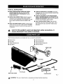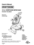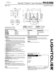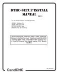
1
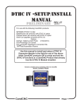
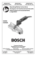
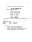
Owner's Manual
IERRFTSMRN'I
ACCESSORIES
FOR MODEL
10 in. (254 mm) COMPOUND
NOS. 315.212100
AND 315.212110
MITER SAW
Item No.
_924310
_924350
Save this manual for
future reference.
_,
•
SAFETY
Read and follow
all Safety Rules and Operating
Instructions
before first use of
•
LOOSE
•
INSTALLATION
this product.
•
SERVICES
CAUTION:
Customer
Help Line: t-800-932-3188
Sears,
Roebuck
and Co., Hoffman
Estates,
IL 60179
Visit the Craftsman
web page: www.sears.com/craftsman
972000-603
2-00
USA
PARTS
READ ALL INSTRUCTIONS
•
READ THESE INSTRUCTIONS
AND THE INSTRUCTIONS
FOR THE 315.212100 COMPOUND MITER SAW THOROUGHLY
before
using accessories.
•
KNOW YOUR POWER
TOOL.
ALWAYS WEAR SAFETY GLASSES. Everyday
eyeglasses have only impact-resistant lenses; they
are NOT safety glasses.
•
ALWAYS DISCONNECT SAW FROM POWER
SUPPLY BEFORE MAKING ADJUSTMENTS OR
ADDING ACCESSORIES. Make sure the switch is
off when reconnecting to power supply.
•
SAVE THESE INSTRUCTIONS. Refer to them
Read the owner's
manual for the Compound Miter Saw carefully.
Learn the saw's applications and timitations as well
as the specific potential hazards related to this
tool,
•
•
frequently and use to instruct other users. If you
loan someone this tool, loan them these instructions also.
KEEP THE WORK AREA CLEAN, Cluttered work
areas and work benches invite accidents. DO NOT
leave tools or pieces of wood on the saw while it is
in operation.
_k
Look for this symbol
to point
out important
means
attention!!!
Your safety
is involved.
safety
precautions.
It
The following accessories are included with item no. 924310 and &2.4350:
•
Work Clamp
•
Small Wing Screw
•
Dust Bag
•
Clamp Bracket (2)
•
Table Extensions (2)
•
Stop Block
• Clamp Bracket Screws (2)
• Owner's Manual
WORKCLAMP
EXTENSIONS
S_CREW
STOPBLOCK
SMALL WINGBCREW
CLAMP BRACKET
Fig. 1
_1, WARNING:
The use of attachments or accessories not listed might be hazardous.
2
_l,
WARNING:
To prevent accidental starting that
could cause possible serious personal injury,
assemble all parts to your saw completely before
connecting
it to power supply. Saw should never
be connected to power supply when you are
assembling parts, making adjustments,
installing
or removing blades or accessories,
or when not
in use.
WORK
DUST BAG
CLAMP
See Figure 2.
The worl_ clamp provides greater control by clamping
the workpiece to the fence. It also prevents the
workpiece from creeping toward the saw blade. This
is very I?elpful when cutting compound miters. To
install the work clamp, place the shaft of the clamp in
either hole in front of the miter table base. Rotate the
knob on the clamp to move it in or out as needed.
_,
EXHAUST PORT
Fig. 3
TABLE
EXTENSIONS
See Figure 4.
To install table extensions, insert the ends of the
extensions into the holes in the sides of the base.
Secure them in place by positioning a clamp bracket
under each table extension beneath the miter table.
Orient each clamp bracket as shown in figure 4.
Secure each clamp bracket in place with a clamp
bracket screw. The clamp bracket screw threads
through the clamp bracket and tightens against
bottom of miter table, securing clamp bracket against
table extension.
WARNING:
Make sure the saw blade or blade
guard will not hit the work clamp assembly when
cutting 35 ° to 45 ° angles. Failure to heed this
warning can result in serious personal injury.
SAWVIEWED
FROMBELOW
WORK
CLAMP
MITER TABLE BASE
DUST
CLAMP
BRACKET
Fig. 2
BAG
See Figure 3.
The dust bag fits over the exhaust port on the upper
blade guard. To install it, remove the dust guide from
the exhaust port. Then, squeeze the two metal clips to
open the mouth of the bag and slide it on the exhaust
port. Release the clips. The metal ring in the bag
should lock in between the grooves on the exhaust
port. For more efficient operation, empty dust bag
when no more than half full. This will permit better air
flow through the bag.
TABLE EXTENSION
Fig. 4
3
STOP
BLOCK
See Figures 5 and 6.
•
Tighten small wing screw securely,
•
The stop block is useful as a stop for cutting multiple
pieces to the same length. It can be installed on either
table extension on either side of the saw base:
Make a test cut in scrap material and measure the
length of the workpiece.
•
Make any necessary adjustments.
•
Slide the stop block on the back arm of either table
extension, then insert the table extension into the
saw base. See Figure 5.
_,
•
Use the small wing screw to secure the stop block
to the table extension. See Figure 5.
•
Loosen the small wing screw and adjust the stop
block the desired distance from the blade for the
cut to be made.
WARNING: When using the work clamp with
the stop block, install the clamp o_ the stop block
side of the blade. This will eliminate the
possibility of the saw catching the loose end and
kicking up. Failure to heed this warning can
result in serious personal injury.
STOP
BLOCK
STOPBLOCK
SMALL
WINGSCREW
MITERSAWBASE
EXTENSION
Fig. 5
Fig. 6