1
Operator's Manual
®
GAR
E
TRACTO
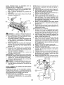
26.0 HR* 54" Mower
Electric Start
Automatic Transmission
Model No.
917.28948
• Espar_ol, p. 36
This product has a low emission engine which operates
differently from previously built engines. Before you start the
engine, read and understand this Owner's Manual.
IMPORTANT:
Read and follow all Safety
Rules and Instructions before
operating this equipment.
For answers to your questions
about this product, Call:
1-800-659-5917
Sears Craftsman Help Line
5 am - 5 pm, Mon - Sat
SEARS, ROEBUCK AND CO., HOFFMAN ESTATES,
Vis it our C raftsman webs ite:www,sears,com/crafts man
429525 Rev. 1
IL 60179
U.S.A.
'As rated by the engine manufacturer
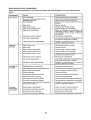
Maintenance ..........................................
21
Sen,ice and Adjustments ......................... 26
Storage ...................................................
31
Trou bleshooting .....................................
32
Sears Service .........................
Back Cover
Warranty ........................................................
2
Safety Rules ............................................
3
Product Specifications
.............................
6
Assembly/Pre-Operation
...............................8
Operation ...............................................
!3
Maintenance
Schedule ..........................
21
CRAFTSMAN
TWO YEARS
FULL WARRANTY
ON RIDING
EQUIPMENT
When operated and maintained according to all supplied instructions, if this riding equipment
fails due to a defect in material or workmanship
within two years from the date or purchase,
call 1-800-4-MY-HOME®
to arrange for free repair.
Also, when operated and maintained according
also cover defects in material and workmanship
from the date of purchase
to all supplied instructions,
VVarranty will
of the Frame and Front Axle for five years
This warranty covers ONLY defects in material and workmanship.
pay for:
Sears will NOT
•
Expendable
items that become worn during normal use, including
blades, spark plugs, air cleaners, belts, and oil filters.
but not limited
°
•
Standard maintenance
servicing, oil changes, or tune-ups.
Tire replacement
or repair caused by punctures from outside
thorns, stumps, or glass.
°
Tire or wheel replacement
operation or maintenance.
-
Repairs necessary
because of operator abuse, including but not limited to damage
caused by towing objects beyond the capability of the riding equipment,
impacting
objects that bend the frame or crankshaft, or over-speeding
the engine.
Repairs necessary because of operator negligence, including but not limited to, electrical
and mechanical damage caused by improper storage, failure to use the proper grade
and amount of engine oil, failure to keep the deck clear of flammable debris, or failure to
maintain the riding equipment according to the instructions contained in the operator's
manual.
•
.
•
or repair resulting
from normal
objects,
to
such as nails,
wear, accident,
or improper
Engine (fuel system) cleaning or repairs caused by fuel determined to be contaminated
or
oxidized (stale)° In general, fuel should be used within 30 days of its purchase date.
Normal deterioration
and wear of the exterior finishes, or product label replacement.
All riding equipment and battery warranty
commercial
or rental purposes.
This warranty
applies
coverage
only while this product
This warranty gives you specific
vary from state to state.
is void if this product
is ever used for
is within the United States.
legal rights,
and you may also have other
Sears, Roebuck and Co., Hoffman Estates, IL 60179
2
rights which
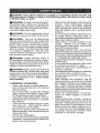
_IbDANGER:
This cutting machine is capable of amputating
hands
throwing objects. Failure to observe the following safety instructions
in serious injury or death.
_AWARNING:
tn order to prevent accidental starting when setting up, transporting,
adjusting or making repairs, always discon_
nect spark plug wire and place wire where
it cannot contact spark plug.
•
all'WARNING:
Do not coast down a hill in
neutral, you may lose control of the tracton
•
and feet and
could result
Never direct discharged materialtoward
anyone.
Avoid discharging
material
against a wall or obstruction.
Material
may ricochet back toward the operator.
Stop the blades when crossing gravel
surfaces,
_WARNING:
Tow only the attachments
that are recommended
by and comply with
specifications
of the manufacturer
of your
tractor. Use common sense when towing.
Operate only at the lowest possible speed
when on a slope. Too heavy of a load, while
on a slope, is dangerous.
Tires can lose
traction with the ground and cause you to
lose control of your tractor.
•
•
•
_WARNING:
Engine exhaust, some of
its constituents, and certain vehicle components contain or emit chemicals known to the
State of California to cause cancer and birth
defects or other reproductive harm_
•
•
,
_WARNING:
Battery posts, terminals and
related accessories
contain lead and lead
•
compounds, chemicals known to the State of
California to cause cancer and birth defects
or other reproductive
harm. Wash hands
after handling.
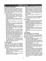
h GENERAL
•
•
•
•
•
•
•
,
•
OPERATION
Read, understand, and foltowallinstructions on the machine and in the manual
before starting.
Do not put hands or feet near rotating
parts or under the machine. Keep clear
of the discharge opening at all times.
Only allow responsible
adults, who are
familiar with the instructions, to operate
the machine
,
•
Clear the area of objects such as rocks,
toys, wire, etc., which could be picked
up and thrown by the blades.
Be sure the area is clear of bystanders
before operating. Stop machine if anyone
enters the area.
Never carry passengers.
Do not mow in reverse unless absolutely
necessar'y'. Always look down and behind
before and while backing.
3
Do not operate machine without the entire grass catcher, discharge
chute, or
other safety devices in place and working.
Slow down before turning.
Never leave a running machine unattended.
Always turn off blades, set
parking brake, stop engine, and remove
keys before dismounting.
Disengage
blades when not mowing.
Shut off engine and wait for all parts to
come to a complete stop before cleaning
the machine, removing the grass catcher,
or unclogging the discharge chute.
Operate machine only in daylight or good
artificial light,
Do not operatethe
machine while under
the influence of alcohol or drugs.
Watch for traffic when operating near or
crossing roadways_
Use extracarewhen
loading or unloading
the machine into a trailer or truck.
Always wear eye protectionwhen
operating machine.
Data indicates that operators,
age 60
years and above, are involved in a large
percentage of riding mower-related
injuries. These operators should evaluate
their ability to operate the riding mower
safely enough to protect themselves and
others from serious injury.
Follow the manufacturer's
recommendation for wheel weights or counterweights.
Keep machine free of grass, leaves or
other debris build-up which can touch hot
exhaust / engine parts and burn. Do not
allow the mower to plow leaves or other
debris which can cause build-up to occur. Clean any oil or fuel spillage before
operating or storing the machine_ Allow
machine to cool before storage.
•
il. SLOPE OPERATION
Slopes are a major factor related to loss of
control and tip-over accidents, which can
result in severe injury or death. Operation
on all slopes requires extra caution.
If you
cannot back up the slope or ifyou feel uneasy
on it, do not mow it.
•
Mow up and down slopes, not across.
, Watch for holes, ruts, bumps, rocks, or
other hidden objects.
Uneven terrain
could overturn the machine.
Tall grass
can hide obstacles.
•
Choose a low ground speed so thai you
will not have to stop or shift while on the
slope.
• Do not mow on wet grass.Tires may lose
traction.
Always keep the machine in gear when
going down slopes. Do not shiftto neutral
and coast downhill.
• Avoid starting, stopping, or turning on a
slope. Ifthetires Iosetraction,
disengage
the blades and proceed slowly straight
down the slope.
•
Keep all movement on the slopes slow
and gradual.
Do not make sudden
changes
in speed or direction, which
could cause the machine to roll over.
•
Use extracare
while operating machine
with grass catchers or other attachments;
they can affect the stability of the machine. Do no use on steep slopes.
.
Do not try to stabilize the machine by
putting your foot on the ground.
•
Do not mow near drop-offs,
ditches,
or embankments.
The machine could
suddenly roll over if a wheel is over the
edge or if the edge caves inn
•
•
Never carry children,
even with the
blades shut off. They may fall off and
be seriously injured or interfere with safe
machine operation. Children who have
been given rides in the past may suddenly
appear in the mowing area for another
ride and be run over or backed over by
the machine.
Never allow children to operate the machine_
Use extra care when approaching blind
corners, shrubs, trees, or other objects
that may block your view of a child.
IV. TOWING
•
•
Tow only with a machine that has a hitch
designed for towing. Do not attach towed
equipment
except at the hitch point.
Foilowthemanufacturer's
recommenda-
•
tion for weight limits for towed equipment
and towing on slopes.
Never allow children or others in or on
°
•
towed equipmenL
On slopes,theweightofthe
towed equipment may cause loss of traction and loss
of control.
Travel slowly and allow extra distance to
stop.
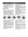
V. SERVICE
SAFE HANDLING
OF GASOLINE
To avoid personal injury or property damage, use extreme care in handling gasoline.
Gasoline is extremely flammable
and the
vapors are explosive.
•
Extinguish all cigarettes, cigars, pipes,
and other sources of ignition.
•
Use only approved gasoline container.
•
Never remove gas cap or add fuel with
the engine running. Allow engine to cool
before refueling.
•
Never fuelthe
machine indoors.
. Neverstore themachine orfuelcontainer
where there is an open flame, spark, or
pilot light such as on a water heater or
other appliances, o
•
Never fill containers inside a vehicle or
on a truck or trailer bed with plastic liner.
Always place containers on the ground
away from your vehicle when filling.
•
Remove gas-powered
equipment from
the truck or trailer and refuel it on the
ground. If this is not possible, then refuel
such equipmentwith
a portable container,
rather than from a gasoline dispenser
nozzle°
Ill. CHILDREN
Tragic accidents can occur if the operator
is not alert to the presence
of children_
Children are often attracted to the machine
and the mowing activity.
Never assume
that children will remain where you last
saw them.
•
Keep children out of the mowing area
and in the watchful care of a responsible
adult other than the operator.
•
Be alert and turn machine off if a child
enters the area.
•
Before and while backing, look behind
and down for small children_
4
•
o
Keepthe nozzle in contactwith the rim
of the fuel tank or containeropeningat
alltimesuntilfuelingis complete.Donot
usea nozzlelock-opendevice.
iffuelisspilledonclothing,changeclothing immediately.
Neveroverfillfueltank.Replacegascap
and tightensecurely,
GENERAL
•
•
•
•
,
•
•
•
•
SERVICE
•
Never operate
machine
in a closed
area.
Keep all nuts and bolts tight to be surethe
equipment is in safe working condition,
Nevertamperwith
safety devices. Check
their proper operation regularly.
Keep machine free of grass, leaves, or
other debris build-up.
Clean oil or fuel
spillage and remove any fuel-soaked debris. Allow machine to cool before storing.
•
•
•
,
Do not mow in reverse unless absolutely
necessary.Always
look down and behind
before and while backing.
Never carry children,
even with the
blades shut off° They may fall off and
be seriously injured or interfere with safe
machine operation.
Children who have
been given rides in the past may suddenly
appear in the mowing area for another
ride and be run over or backed over by
the machine.
•
Keep children out of the mowing area
and in the watchful care of a responsible
adult other than the operator.
Be alert and turn machine off if a child
enters the area.
•
•
•
,
•
5
If you strike a foreign object, stop and
inspect the machine. Repair, if necessary,
before restarting.
Never make any adjustments or repairs
with the engine running.
Check grass catcher components and the
discharge chute frequently and replace
with manufacturer's
recommended parts,
when necessary.
Mower blades aresharp. Wrapthe blade
or wear gloves, and use extra caution
when servicing them.
Checkbrakeoperationfrequently.
Adjust
and service as required.
Maintainorreplacesafetyandinstruction
labels, as necessary.
Be sure the area is clear of bystanders
before operating. Stop machine if anyone
enters the area.
Nevercarry
passengers.
Before and while backing, look behind
and down for small children.
Mow up and down slopes (15 ° Max), not
across.
Choose a low ground speed so that you
will not have to stop or shift while on the
slope.
Avoid starting, stopping, or turning on a
slope. If the tires lose traction, disengage
the blades and proceed slowly straight
down the slope.
If machine
stops while going uphill,
disengage blades, shift into reverse and
back down slowly.
Do not turn on slopes unless necessary,
and then, turn slowly
and gradually
downhill, if possible.
PRODUCT
SPECIFICATIONS
REPAIR
Gasoline Capacity
and Type:
4 Gallons
Unleaded Regular
Oil Type
(API-SG-SL):
SAE 10W30(above 32°F)
SAE 5W30(below 32°F)
Oil Capacity:
Spark
Ground
Congratulations on making a smart purchase.
Your new Craftsman® product is designed
and manufactured for years of dependable
operation. But like all products, it may require
repair from time to time. That's when having
a Repair Protection Agreement can save you
money and aggravation.
Champion RCI2YC
(Gap: .030")
Speed
Forward:
Reverse:
Purchase a Repair Protection Agreement
now and protect yourself from unexpected
hassle and expense.
0 - 7.8
0 - 2.1
Charging System:
15 Amps @ 3600 RPM
Battery:
AmpiHr:
Min. CCA:
Case size:
Blade Bolt
AGREEMENTS
64 oz
Plug:
PROTECTION
Here's
28
230
U 1R
45-55 Ft, Lbs,
Torque:
what's included
in the Agreement:
-
Expert service by our 12,000 professional
repair specialists.
•
Unlimited service and no charge for parts
and labor on all covered repairs.
Product replacement
product can't be fixed,
CONGRATULATIONS
on your purchase of
a new tractor. It has been designed, engineered and manufactured to give you the best
possible
dependability
and performance.
covered
Discount of !0% from regular price of
service and service-related
parts not
covered by the agreement; also, 10% off
regular price of preventive maintenance
check,
Should you experience any problem you cannot easily remedy, please contact a Sears or
other qualified service center. We have competent, well-trained representatives
and the
proper tools to service or repair this tractor.
Please read and retain this manual. The
instructions
will enable you to assemble
and maintain your tractor properly, Always
observe the "SAFETY RULES".
CUSTOMER
if your
Fast help by phone - phone support
from a Sears representative
on products
requiring in-home repair, plus convenient
repair scheduling.
Once you purchase
the Agreement,
a
simple phone call is all that it takes for you
to schedule service. You can call anytime
day or night, or schedule a service appointment online.
RESPONSIBILITIES
. Read and observe the safety rules.
. Follow a regular schedule in maintaining,
caring for and using your tractor,
• Follow the instructions under "Maintenance" and "Storage"
sections
of this
owner's manual
Sears has over 12,000 professional
repair
specialists,
who have access to over 4.5
million quality parts and accessories. That's
the kind of professionalism
you can count on
to help prolong the life of your new purchase
for years to come. Purchase your Repair
Protection Agreement
todayf
_IbWARNING:
This tractor is equipped with
an internal combustion engine and should not
be used on or near any unimproved forestcovered, brush-covered
or grass-covered
land unless the engine's exhaust system is
equipped with a spark arrester meeting applicable local or state laws (if any). If a spark
arrester is used, it should be maintained in
effective working order by the operator.
In the state of Californiathe above is required
by taw (Section 4442 of the California Public
Resources
Code). Other states may have
similar laws. Federal laws apply on federal
lands. A spark arrester for the muffler is
available through you r nearest Sears service
center (See REPAIR PARTS manual)°
Some limitations
and exclusions
apply.
For prices and additional
information
call
1-800-827-6655.
SEARS INSTALLATION
SERVICE
For Sears professional installation of home
appliances,
garage door openers,
water
heaters, and other major home items, in the
U,S,A. call 1-8004-MY-HOME®
6
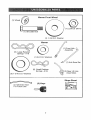
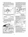
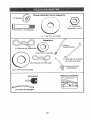
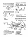
(1) Wheel __
Mower
Front Wheel
(1) Locknut
_
(li ,houlder
3/8-16
Bo_lt
_
(1) 1-1/40oDo
Washer
Mower
(1) Front Link
(5)
Large Retainer
Springs - 7/16
(1) 3/40,Do
Washers
(1) Anti-Swar
(2) Small Retainer
Springs - 5/16
(5) 1-3/16 O,D. Washers
(2) Rear Lift Link
Assemblies
Slope
(1) Oil Drain Tube
For Future Use
Sheet
Bar
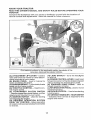
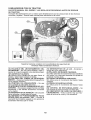
Your new tractor has been assembled
at the factory with exception of those parts left
unassembled for shipping purposes.
To ensure safe and proper operation of your tractor
all parts and hardware you assemble must be tightened securely,
Use the correct tools
as necessary to ensure proper tightness.
TOOLS
REQUIRED
A socket wrench
easier. Standard
FOR
Utility
(1) t/2" wrench
Tire pressure
(I) 3/4" wrench
knife
gauge
Pliers
w/ddve
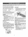
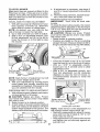
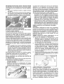
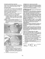
SEAT
1. Sit in seal
2, Lift up adjustment lever (A) and slide seat
until a comfortable
position is reached
which allows you to press clutch/brake
pedal all the way down.
3. Release lever to lock seat in position.
set wilt make assembly
wrench sizes are listed.
(2) 7/16" wrenches
(1) 3/4" socket
ADJUST
ASSEMBLY
ratchet
When right or left hand is mentioned in this
manual, it meanswhen you are in the operating
position (seated behind the steering wheel).
TO REMOVE
TRACTOR
FROM
CARTON
UNPACK
,
•
•
•
CARTON
Remove all accessible loose parts and
parts cartons from carton,
Cut along dotted lines on all four panels
of carton. Remove end panels and lay
side panels flat.
Remove mower and packing materials,
Check for any additional loose parts or
cartons and remove.
BEFORE REMOVING
FROM SKID
TO CHECK
NOTE: You may now roll your tractor offthe
skid, Follow the appropriate instruction below
to remove the tractor from the skid.
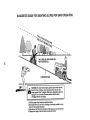
WARNING:
Before starting, read, understand and follow all instructions
in the
TRACTOR
Operation section of this manual. Be sure
tractor is in a well-ventilated
area. Be sure
the area in front of tractor is clear of other
BATTERY
people and objects.
1, Lift hood to raised position.
TO ROLL TRACTOR OFF SKID
NOTE: if this battery is put into service after
month and year indicated on label (label is
located between terminals) charge battery
for minimum of one hour at 6-10 amps, (See
"BATTERY" in Maintenance
section of this
manual for charging instructions).
•
(See
Operation
section
for location
and
function
of controls)
1_ Raise attachment lift lever to its highest
position,
2. Release parking brake by depressing
brake pedal
3, Place freewheel control in disengaged
position to disengage transmission
(See
"TO TRANSPORT"
inthe Operation section of this manual).
4, Roll tractor forward off ski&
Forbatteryandbatterycableinstallationsee
"REPLACING
BATTERY" in the "Service
and Ad ustments" section in this manual.
8
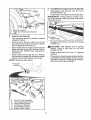
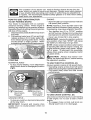
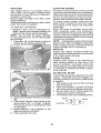
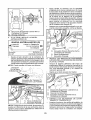
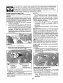
TO INSTALL
MOWER
Assemble front gauge wheel (W) to
front of mower.
.
1, Set parking brake lever and Power
attachment
lift lever
Depress clutch/brake
down and holdo
pedal all the way
Pull parking brake lever up and hold,
release pressure from clutch/brake pedal,
then release parking brake lever. Pedal
should remain in brake position. Ensure
parking brake will hold tractor secure.
Ho Front Mower Bracket
W, Front Gauge Wheel
3, Turn steering
mower.
wheel
X, Shoulder Bolt
Y, 1¼ 0oDoWasher
Z, 3/8-16 Locknut
left and position
• Turn steering wheel to the left as far as it
will go and position mower on right side of
tractorwith deflector shield (Q) to the right.
_CAUTION:
Lift lever is spring loaded.
Have a tight grip on lift lever, lower it slowly
and engage in lowest position_ Lift lever is
located on left side of fender.
Front
Li_
Lever
Transaxle
Q_ Deflector
Shield
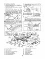
A.,
B,
C,
D,
Eo
E
Ho
Mower Side Suspension Arms
Retainer Spring
Rear Lift Link(s)
Right Side Rear Mower Bracket
Front Lift Link Assembly
Front Suspension Bracket
Front Mower Bracket
tv
Ko
L.
M,,
Q,
S.
W.
9
Left Side Rear Mower Bracket
Belt Tension Rod
Locking Bracket
Engine Clutct_ Pulley
Deflector Shield
Anti-Sway Bar
Front Gauge Wheel
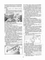
4.
Slide mower under tractor.
•
Bring belt forward and check belt for
proper routing in all mower pulley grooves.
o
NOTE: Be sure mower side suspension
arms (A) are pointing forward before sliding
mower under tractor.
•
Slide mower under tractor
centered under tractor.
until
it is
•
Pivot the integrated washer end of antisway bar (S) towards mower deck bracket
on right side of mower. Insert integrated
washer end of bar into hole in rear mower
bracket (D). Move mower as needed to
insert integrated washer end of bar into
rear mower bracket (D).
Secure with small washer and small
retainer spring as shown°
)
c
D, Right Side Rear
Mower Bracket
S. Anti-Sway Bar
T. Transaxle Bracket
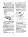
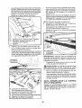
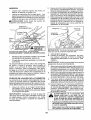
5. Install anti-sway bar (S) (If equipped)
Anti-Sway
Bar (S)
Towards'_.t_
Mower Deck""
90 ° End
,
Attach mower side suspension
(A) to chassis.
•
Position front hole in side suspension arm
(A) over pin on outside of tractor chassis
and secure with large washer and large
retainer spring (B),
•
Repeat on opposite
Integrated Washer End
From right side of mower, first insert
90 ° end of anti-sway bar (S) into hole in
transaxle bracket (T), located near left
rear tire in front of transaxte.
NOTE:
6,
Flashlight
Anti-Sway Bar
(s) Location
arms
side of tractor.
may be helpful.
il
s_
_.
/
Transaxle Bracket (T)
Located Between Rear Tires
A, Mower Side Suspension Arms
B° Retainer Spring
D. Right Side Rear Mower Bracket
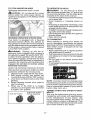
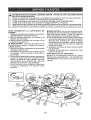
7. Attach
•
NOTE: Depending on model, bracket (T) may
be different than shown but hole for anti-sway
bar will be in same position/location.
'I0
rear lift links
(C)
•
Insert rod end of rear lift link (C) into hole
(U) in tractor lift shaft suspension
arm
and pivot link down to mower,
Lift rearcorner of mower and position slot
in link assembly over pin on rear mower
bracket (D) and secure with large washer
and large retainer spring,
•
Repeat on opposite
side of tractor_
\
9
Install Belt On Engine Clutch Pulley (M)
,
Disengage
belt tension
locking bracket (L),
rod
(K) from
•
install beltonto engine clutch pulley (M),
IMPORTANT:
Check belt for proper routing in all mower pulley grooves and under
mandrel covers,
Rear Lift Link(S)
Right Side Rear Mower Bracket
Hole
8
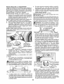
Attach
,
Turn steering wheel to position wheels
straight forward,
From front of tractor, insert rod end of
front link (E) through front hole in tractor
front suspension bracket (F).
Move to left side of mower and and insert
large retainer spring (G) through hole in
front link (E) behind front suspension
bracket (F).
•
•
•
front
link (E)
M,Engine
Clutch Pulley
•
Requires
Raise attachment
position.
lift lever
to highest
If necessary, adjust gauge wheels before
operating mower as shown in the owner's/
operator's manual Check gaugewheels,
deck level and rake settings.
deck lifting°
Front Link
Location
/
Eo
R
G.
Ho
J.
M,
rod (K) on locking
_CAUTION:
Belt tension
rod is spring
loaded, Have a tight grip on rod and
engage slowly.
Insert other end of link (E) into hole in
front mower bracket (H) and secure with
washer and small retainer spring (J),
NOTE:
Engage belt tension
bracket (L),
Front Lift Link Assembly
Front Suspension Bracket
Large Retainer Spring
Front Mower Bracket
Small Retainer Spring
Engine Clutch Pulley
tl
CHECK
TIRE
PRESSURE
The tires on your tractor were over-inflated
at the factory for shipping purposes. Correct
tire pressure
is important for best cutting
performance.
• Reduce tire pressureto PSI shown ontires.
CHECK
DECK
Please review the following
LEVELNESS
For best
should be
MOWER"
section of
cutting results, mower housing
properly leveled. See "TO LEVEL
in the Service and Adjustments
this manual.
CHECK
FOR
ALL
Before you operate your new tractor, we
wish to assure that you receive the best
performance
and satisfaction
from this
Quality Product,
PROPER
POSITION
_/' All assembly
completed°
J' No remaining
OF
See the figures that are shown for replacing
motion and mower blade drive belts in the
Service and Adjustments section of this manual. Verify that the belts are routed correctly.
BRAKE
have
been
loose parts in carton.
J'Battery
is properly
prepared
and
charged°
V" Seat is adjusted comfortably
and tightened securely.
BELTS
CHECK
checklist:
instructions
All tires are properly inflated. (For shipping purposes, the tires were overinflated
at the factory).
v# Be sure mower deck is properly leveled
side-to-side/front-to-rear
for best cutting
results. (Tires must be properly inflated
for leveling).
_/Check
mower and drive betts_ Be sure
they are routed properly around pulleys
and inside all belt keepers.
#f Check wiring.
See that all connections
are still secure and wires are properly
clamped.
J" Before driving tractor, be sure freewheel
control
is in "transmission
engaged"
position (see "TO TRANSPORT"
in the
Operation section of this manual).
SYSTEM
After you learn how to operate your tractor,
check to see thatthe brake is operating properly. See"TO CHECK B RAKE" in the Service
and Adjustments
section of this manual.
While learning how to use your tractor, pay extra attention to the following important items;
J"
Engine oi! is at proper level.
Fuel tank is filled with fresh, clean, regular
unleaded gasoline°
_' Become familiar with all controls, their
location and function.
Operate them
before you start the engine.
_" Be sure brake system is in safe operating
condition.
_" Be sure Operator Presence System and
Reverse Operation System (ROS) are
working properly (See the Operation and
Maintenance sections in this manual).
_/" It is important to purge the transmission
before operating your tractor for the first
time. Follow proper starting and transmission purging instructions (See 'q'O START
ENGINE" and "PURGE TRANSMISSION"
in the Operation section of this manual).
12
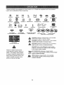
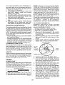
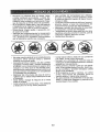
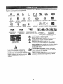
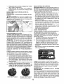
These symbols may appear on your tractor
Learn and understand their meaning.
R
N
H
L
REVERSE
NEUTRAL
HIGH
LOW
or in literature
CHOKE
supplied
FAST
with the product.
SLOW
IGNITION SWITCH
IPmHI
ENGINE OFF
REVERSE
OPERATION
SYSTEM (ROS)
LIGHTS ON
FUEL
ENGINE ON
BATTERY
ENGINE START
REVERSE
PARKING BRAKE
FORWARD
CRUISE
MOWER HEIGHT
CONTROL
MOWER LIFT
CLUTCH/BRAKE
PEDAL
®@@@@
ATirACHMENT
CLUTCH
DISENGAGED
ATTACHMENT
CLUTCH
ENGAGED
DANGER, KEEP HANDS
AND
FEET
AWAY
KEEP AREA CLEAR
SLOPE HAZARDS
(SEE SAFETY RULES SECTION)
DANGER indicates a hazard which, if nol avoided,
will result in death or serious injury,
FREE WHEEL
(Automatic Models only)
&
Failure to follow instructions
could result in serious injury or
death. The safety alert symbol
is used to identify safety information about hazards which can
result in death, serious injury
and/or property damage.
WARNING indicates a hazard which, if not avoided,
could result In death or serious injury°
&
CAUT]ON indicates a hazard which, if not avoided,
might result in minor or moderate injury_
CAUTION when used without the aled symbol,
indicates a situation that could result in damage
to the tractor and/or engine.
HOT SURFACES indicates a hazard which,
if not avoided, could result in death, serious
andlor property damage.
FIRE indicates a hazard wMch, if not avoided,
could result tn death, serious Injury and/or
property damage.
13
injury
KNOW
YOUR
TRACTOR
READ THIS OWNER'S
TRACTOR
MANUAL
AND SAFETY
RULES
BEFORE
OPERATING
Compare the illustrations with your tractor to familiarize yourself with the locations
various controls and adjustments.
Save this manual for future reference.
YOUR
of
_ilil
¸_!
:'ili_i!
_!
_::i:_:
ii_:
!_:
i_
__i_i::_,:_!_
,:_i
_:_ii:
_!i:_i
i¸_ii ::i_i_:_
i.............
Our tractors
conform
American
to the applicable safety standards
National Standards Institute°
(A) ATTACHMENT
LIFT LEVER - Used to
raise and lower the mower or other attach_
ments mounted to your tractor.
(B) BRAKE PEDAL - Used for braking the
tractor and starting the engine°
(C) PARKING BRAKELocks clutch!brake
pedal into the brake position.
(D) THROTTLE CONTROLUsed to control engine speed.
(E) ATTACHMENT
CLUTCH
SWITCH
- Used to engage the mower blades, or other
attachments
mounted to your tractor.
(F) IGNITION SWITCH - Used for starting
and stopping the engine.
(G) REVERSE
OPERATION
SYSTEM
(ROS) "ON" POSITIONAllows operation
of mower or other powered attachment while
in reverse.
of the
(H) LIGHT SWITCH - Turns the headlights
on and off.
(J) CRUISE CONTROL LEVER - Used to set
forward movement of tractor at desired speed
without holding the forward drive pedal.
(K) FORWARD
DRIVE PEDAL - Used for
forward movement of tractor..
(L) REVERS E DRIVE PEDAL- Used for reverse
movement of tractor..
(N) CHOKECONTROLUsedwhen starting
a cold engine.
(P) SERVICE REMINDER / HOUR METER
- Indicates when service is required for the
engine and mower.
14
The operation of any tractor can result in foreign objects thrown into the
eyes, which can result in severe eye damage.
Always wear safety glasses
or eye shields while operating your tractor or performing any adjustments
or repairs. We recommend standard safety glasses or a wide vision safety
mask worn over spectacles.
HOW
TO USE
YOUR
TO SET PARKING
ENGINE
TRACTOR
BRAKE
Your tractor is equipped with an operator
presence sensing switch, When engine is
running, any attempt by the operator to leave
the seatwithout first setting the parking brake
will shut off the engine_
1, Depress brake pedal (B) allthe way down
and hold_
2, Pull parking brake lever (C) up and hold,
release pressure from brake pedal (B),
then release parking brake lever. Pedal
should remain in brake position_ Make
sure parking brake will hold tractor secure.
-
• Move throttle control (D) between half and
full speed (fast) position.
NOTE: Failure to move throttle control between half and full speed (fast) position, before stopping, may cause engine to "backfire",
° Turn ignition key (F) to "STOP" position
and remove key. Always remove key when
leaving tractorto prevent unauthorized use,
. Never use choke (N) to stop engine.
IMPORTANT:
Leaving the ignition switch in
any position other than "STOP" will cause
the battery to discharge and go dead°
NOTE: Under certain conditions when tr,actor
is standing idle with the engine running, hot
engine exhaust gases may cause "browning" of grass. To eliminate this possibility,
always stop engine when stopping tractor
on grass areas.
CAUTION:
Always stop tractor completely, as described above, before leaving
the operator's position.
STOPPING
MOWER
BLADES
-
TO USE THROTTLE
- To stop mower blades, move attachment
clutch clutch lever to disengaged position
(r_)
Attachment
Clutch Switch
"Engaged"
GROUND
DRIVE
CONTROL
(D)
Always operate engine at full speed (fast).
• Operating engine at less than full speed
(fast) reduces engine's operating efficiency°
• Full speed (fast) offers the best mower
performance.
(l'_)Attachment
Clutch Switch
"Disengaged"
TO USE CHOKE CONTROL
(N)
Use choke control whenever you are starting
a cold engine, Do not use to start a warm
engine.
• To engage choke control, pull knob out.
Slowly push knob in to disengage_
-
• _fb stop ground drive, depress brake pedal
al! the way down.
IMPORTANT:
Forward and reverse drive
pedals return to neutral position when not
depressed.
15
TO MOVE FORWARD
AND
BACKWARD
The cutting height range is approximately
1" to 4"° The heights are measured from the
ground to the blade tipwith the engine not running. These heights are approximate and may
vary depending upon soil conditions, height
of grass and types of grass being mowed.
• The average lawn should be cut to approximately 2-1t2" during the cool season
and to over 3" during hot months.
For
healthier and better looking lawns, mow
often and after moderate growth,
• For best cutting performance,
grass over
6" in height shoutd be mowed twice. Make
the first cut relatively high; the second to
desired height.
The direction and speed of movement
is
controlled by the forward and reverse drive
pedals.
1. Start tractor
and release
parking
brake,
2. Slowlydepressforward(K)
orreverse(L)
drive pedal to begin movemenL Ground
speed increases the further down the
pedal is depressed,
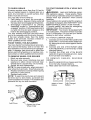
TO ADJUST
GAUGE
WHEELS
Gauge wheels are properly adjusted when
they are slightly off the ground when mower
is at the desired cutting height in operating
position, Gauge wheels then keep the deck
in proper position to help prevent scalping
in most terrain conditions.
TO USE CRUISE CONTROL
The cruise control feature can be used for
forward travel only,
SYSTEM CHARACTERISTICS
The cruise control should only be used
while mowing or transporting
on relatively
smooth, straight surfaces_ Other conditions
such as trimming at slow speeds may cause
the cruise control to disengage° Do not use
the cruise control on slopes, rough terrian
or while trimmimg or turning,
, With forward drive pedal depressed
to
desired speed, pult cruise control lever
(J) up and hold while lifting your foot off
the pedal, then release the lever.
To disengage the cruise control, depress the
brake pedal, tap on forward drive pedal or
push the cruise control lever down.
TO ADJUST MOWER CUTTING HEIGHT
NOTE: Adjust gauge wheels with tractor on
a flat level surface,
1. Adjust mower to desired cutting height
(See "TO ADJUST MOWER CUTTING
HEIGHT" in this section of manual).
2, With mower in desired height of cut position, gauge wheels should be assembled
so they are slightly offthe ground. Install
gauge wheel in appropriate hole, Tighten
securely.
3. Repeat for all, installing gauge wheel in
same adjustment hole,
The position of the attachment lift lever (A)
determines the cutting height,
• Put attachment lift lever in desired cutting
height slot,
• Slide pointer tab (T) to desired cutting
height as a reminder for next time you mow°
TO OPERATE
MOWER
Your tractor is equipped with an operator
presence sensing switch, Any atte rapt by the
operator to leave the seat with the engine
running and the attachment clutch engaged
will shut off the engine_ You must remain
fully and centrally positioned in the seat to
prevent the engine from hesitating or cutting
offwhen operating your equipment on rough,
rolling terrain or hills.
1o Select desired height of cut with attachment lift lever.
2. Start mower blades by engaging attachment clutch control.
16
TO STOP
Disengage
MOWER
BLADES
attachment
TO OPERATE ON HILLS
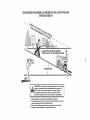
_WARNING:
Do not drive up or down
hills with slopes greater than 15 ° and do not
drive across any slope. Use the slope guide
provided at the back of this manual.
- Choose the slowest speed before starting
up or down hills,
, Avoid stopping
or changing
speed on
hills.
• If stopping is absolutely necessary, push
brake pedal quickly to brake position and
engage parking brake.
• To restart movement, slowly release parking brake and brake pedal°
, Slowly depress appropriate drive pedal to
slowest setting.
° Make all turns slowly.
clutch control
_CAUTION:
Do not operate the mower
without either the entire grass catcher, on
mowers so equipped, or the deflector shield
(S) in place.
REVERSE
OPERATION
SYSTEM
(ROS)
TO TRANSPORT
"four tractor is equipped with a Reverse
Operation System (ROS). Any attempt by
the operator to travel in the reverse direction
with the attachment clutch engaged will shut
off the engine unless ignition key is placed
in the ROS "ON" position_
When pushing or towing your tractor, be
sure to disengage transmission
by placing
freewheel control in freewheeling
position.
Free wheel control is located at the rear
drawbar of t_actor.
• Raise attachment
lift to highest position
with attachment lift control.
• Pullfreewheel
control out and into the slot
and release so it is held in the disengaged
position,
• Do not push or tow tractor at more than
two (2) MPH.
• To reengage transmission,
reverse above
procedure.
_WARI',IING:
Backing up with the at=
tachment clutch engaged while mowing is
strongly discouraged.'liarning
the ROS "ON",
to allow reverse operation with the attachment clutch engaged, should only be done
when the operator decides it is necessary to
reposition the machine-with the attachment
engaged. Do not mow in reverse unless
absolutely
necessary.
USING THE REVERSE OPERATION SYSTEM
Only use if you are certain no children or other
bystanders will enter the mowing area°
1, Depress brake pedal all the way down.
2, With engine running, turn ignition key
counterclockwise
to ROS "ON" position.
3. Look down and behind before and while
backing.
4. Slowly depress reverse drive pedal to
start movement°
NOTE: To protect hood from damage when
transporting your tractor on a truck or atrailer,
be sure hood is closed and secured to tractor.
5, When use of the ROS is no longer
needed, turn the ignition key clockwise
to engine "ON" position°
ROS "ON" Position
Use an appropriate means of tying hood to
tractor (rope, cord, etc.).
TOWING
MENTS
Engine "ON" Position
(Normal Operating)
CARTS
AND
OTHER
ATTACH-
Tow only the attachments
that are recommended by and comply with specifications
of the manufacturer
of your tractor, Use
common sense when towing, Too heavy of
a load, while on a slope, is dangerous_ Tires
can lose traction with the ground and cause
you to lose control of your tractor.
17
SERVICE REMINDER/HOUR
METER
Service reminder shows the total number
of hours the engine has run and flashes to
indicate that the engine or mower needs servicing. When service is required, the service
reminder will flash for two hours. To service
engine and mower, see the Maintenance
section of this manual.
NOTE: Service reminder
runs when the
ignition key is in any position but "STOP".
For acurate reading, be sure key remains
in the "STOP" position when engtne is not
running.
BEFORE
STARTING
THE ENGINE
CHECK
ENGINE
CAUTION:
Alcohol blended fuels (called
gasohol or using ethanol or methanol) can
attract moisture which leads to separation
and formation of acids during storage. Acidic
gas can damage the fuel system of an engine
while in storage° To avoid engine problems,
the fuel system should be emptied before
storage of 30 days or longer. Drain the gas
tank, start the engine and let it run until the
fuel lines and carburetor are empty. Usefresh
fuel next season. See Storage Instructions
for additional information.
Never use engine
or carburetor cleaner products in the fuel tank
or permanent damage may occur.
OIL LEVEL
The engine in yourtractor
has been shipped,
from the factory, already filled with summer
weight oil.
!. Check engine oil with tractor on level
groun&
2. Unthread and remove oil fill cap/dipstick;
wipe oil off° Reinsert the dipstick into the
tube and rest oil fill cap on the tube. Do
not thread the cap onto the tuber Remove
and read oil level, if necessary, add oil
until "FULI_ mark on dipstick is reached.
Do not overfill.
3. For cold weather operation you should
change oil for easier starting (See the oil
viscosity chart in the Maintenance section
of this manual).
4. To change engine oil, seethe Maintenance
section in this manual.
5. Fill fuel tank to bottom of filler neck. Do
not overfill. Use fresh, clean, regular
unleaded gasoline with a minimum of
87 octane. (Use of leaded gasoline will
increase carbon and lead oxide deposits
and reduce valve life). Do not mix oil
with gasoline.
Purchase fuel in quantities that can be used within 30 days to
u_elaSsure fuel freshness.
CAUTION:
Wipe off any spilled oil or
. Do not store, spill or use gasoline
near an open flame.
IMPORTANT:
When operating in temperatures below 32°F(0°C), use fresh, clean
winter grade gasoline to help ensure good
cold weather starting.
RESERVE FUEL VALVE OPERATION
1_ Raise seat to access reserve fuel
valve,
2, In normal operation, valve should be
set to primary (as shown in view)
3. If tractor runs out of fuel, rotate valve
handle to reserve.
4o Drive tractor to be refueled.
5. After refueling, return valve to primary
position.
Reserve
Fuel Valve
@
Primary
TO START
ENGINE
When starting the engine for the first time or
if the engine has run out of fuel, it will take
extra cranking time to move fuel from the
tank to the engine.
1. Be sure freewheel control is in the transmission engaged position.
2. Sit on seat in operating position, depress
brake pedal and set parking brake.
3o Move attachment clutch to disengaged
position.
4. Move throttle control to fast position
5. Pull choke control out for a cold engine
start attempt. For a warm engine start
attempt the choke control may not be
needed.
NOTE: Before starting, read the warm and
cold starting procedures below_
18
6.
PURGE
Insert key into ignition and turn key
clockwise to start position and release
key as soon as engine starts. Do not run
starter continuously for more than fifteen
seconds per minute, if the engine does
not start after several attempts,
push
choke control in, wait a few minutes and
try again. If engine still does not start, pull
the choke control out and retry.
WARM WEATHER
and above)
STARTING
_t_CAUTION:
Never engage or disengage
freewheel lever while the engine is running.
To ensure proper operation and performance,
it is recommended
that the transmission be
purged before operating tractor for the first
time. This procedure will remove any trapped
air inside the transmission
which may have
developed during shipping of your tractor,
(50°F/10°C
IMPORTANT:
Should your transmission
require removal for service or replacement,
it shoutd be purged after reinstallation before
operating the tractor.
7. When engine starts, slowly push choke
control in until the engine begins to run
smoothly.
If the engine starts to run
roughly, pullthe choke control out slightly
for a few seconds and then continue to
1. Place tractor safely on a level surface that is clear of objects and open - with
engine off and parking brake set.
2o Disengage
transmission
by placing
freewheel control in disengaged position
(See "TO TRANSPORT"
in this section
of manual).
3, Sitting in the tractor seat, start engine.
After the engine is running, move throttle
control to slow position. Disengage parking brake.
push the control in slowly°
8oThe attachments
and ground drive can
now be used. If the engine does not accept
the load, restart the engine and allow it to
warm up for one minute using the choke
as described above.
COLD WEATHER
and below)
STARTING
(50°F/10°C
9_ When engine starts, slowly push choke
control in until the engine begins to run
smoothly. Continue to push the choke
control in small steps allowing the engine
to accept small changes in speed and
load, until the choke control is fully in.
If the engine starts to run roughly, pull
the choke control out slightly for a few
seconds and then continue to push the
control in slowly. This may require an
engine warm-up
period from several
seconds to several minutes, depending
on the temperature.
AUTOMATIC
TRANSMISSION
WARM
_CAUTION:
At any time, during step 4,
there may be movement of the drive wheels,
4,. Depress forward drive pedalto full forward
position and hold for five (5) seconds and
release pedal° Depress
reverse drive
pedal to full reverse position and hold
for five (5) seconds and release pedal.
Repeat this procedure three (3) times.
5. Shutoff engine and set parking brake.
6o Engage transmission
by placing freewheel control in engaged position (See
"TO TRANSPORT"
in this section of
manual),
7, Sitting in the tractor seat, start engine.
After the engine is running, move throttle
control to half (1/2) speed. Disengage
parking brake.
8. Drive tractor forward for approximately
five feet then backwards
for five feel
Repeat this driving
procedure
three
times.
UP
Before driving the unit in cold weather, the
transmission should be warmed up as follows:
1.
TRANSMISSION
Be sure the tractor is on level ground_
2.
Release the parking brake and let the
brake slowly return to operating position.
3. Allow one minute for transmission
to
warm up. This can be done during the
engine warm up period°
4. The attachments
can be used during the
engine warm-up period after thetransmission has been warmed up and may require
the choke control be pulled out slightly°
NOTE: if at a high altitude (above 3000 feet)
or in cold temperatures
(below 32°F/0°C)
the carburetor fuel mixture may need to be
adjusted for best engine performance
(see
"TO ADJUST CARBURETOR"
in the Service
and Adjustments
section of this manual).
Your transmission is now purged
ready for normal operation.
19
and now
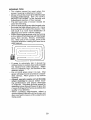
MOWING TiPS
• Tire
chains
cannot
be used
when
the
mower housing is attached to tractor°
, Mowershoutd
be properly leveled for best
mowing performance,
See "TO LEVEL
MOWER HOUSING"
in the Service and
Adjustments
section of this manual.
, The left hand side of mower should be
used for trimming.
• Drive so that clippings are discharged onto
the area that has already been cut. Have
the cut area to the right of the tractor. This
will result in a more even distribution of
clippings and more uniform cutting.
, When mowing large areas, start by turning
to the right so that clippings will discharge
away from shrubs, fences, driveways,
etc. After one or two rounds, mow in the
opposite direction making left hand turns
until finished,
f
.
tf grass is extremely
tail, it should be
mowed twice to reduce load and possible
fire hazard from dried clippings.
Make
first cut relatively high; the second to the
desired height.
° Do not mow grass when it is wet. Wet
grass will plug mower and leave undesirable clumps.
Allow grass to dry before
mowing.
• Always operate engine at full throttle
when mowing
to assure better mowing performance
and proper discharge
of material.
Regulate ground speed by
selecting a low enough speed to give the
mower cutting performance as welt as the
quality of cut desired.
• When operating
attachments,
select a
ground speed that will suit the terrain and
give best performance
of the attachment
being used.
20
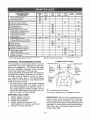
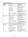
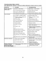
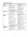
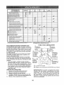
MAINTENANCE
SCHEDULE
eEFOnE
EACH
USE
,,:Chectt; Brake Operation
.......................
T
Check Operator
A
Check for Loose Fasteners
C
,ChectdReplace
T
Lubrication
0
Check Battery
R
P[esence
HOURS
25
& ROS Systems
I
J
EVERY
EVERY
_o
HOURS
EVERY
_so
HOURS
:
STORAGE
:
v"
Blades
Vr3
...................................
v'
J,,
Level
and Terminals
v'
6/
Debris Of! Ste.ering Plate
BEFORE
s_so.
v'
Chart
C!ean Battery
Clean
EVERY
.
..................
_ .......................
V
Check Tire Pressure
Mower
EVERY
HOURS
.
:
:
..............................
V w
I_s
Cheek Transax_e Cooling
Check Mower Levelness
v"
Check V-Belts
Check Engine
Chanqe
Oil Level ..............................................
Engine
V_!,2
O!I (wi!b oil fil{er)
Change Engine Oil (without oil liI_er)
Clean Air Fliler
G
!
N
E
Clean Air Screen.................................
Inspect
MulfIer/Spark
Replace
Clean Eng!ne
Replace
Arrestor
..........
................... "
Oil Filter (if equipped)
Cooling Fine
Spark Plug
GENERAL
.......................................
1.
2,
3,
4.
5.
............
Fuer Filler
LUBRICATION
RECOMMENDATIONS
The warranty on this tractor does not cover
items that have been subjected to operator
abuse or negligence.
To receive full value
from the warranty, operator must maintain
tractor as instructed in this manual,
Some adjustments will need to be made periodically to properly maintain your tractor.
At least once a season, check to see if
you should make any of the adjustments
described in the Service and Adjustments
section of this manual.
• At least once a year you should replace
the spark plug, clean or replace air filter,
and check blades and belts for wear. A
new spark plug and clean air filter assure
proper air-fuel mixture and help your engine run better and last longer.
BEFORE
_,2
.............
Replace Air Fitter Paper Cartridge
Replace
'
EACH
_., Spindle
CHART
Zerk
Front
Wheel
Bearing
zerk
Front
Wheel
Bearing
zerk
_
Steering
Engine
Sector
Gear
Teeth
_,
Mandrel
Zerks
General Purpose Grease
(_) Refer to Maintenance "ENGINE" Section
USE
Check engine oil level°
Check brake operation,
Check tire pressure.
Check operator presence and
ROS systems for proper operation.
Check for loose fasteners,
IMPORTANT:
Do not oilor grease the pivot
points which have special nylon bearings.
Viscous lubricants will attract dust and dirt
that will shorten the life of the self-lubricating
bearings. If you feel they must be lubricated,
use only a dry,, powdered graphite type lubricant sparingly.
21
TRACTOR
Always observe safety rules when performing
any maintenance.
BRAKE OPERATION
If tractor requires more than five (5) feet to
stop at highest speed in highest gear on a
level, dry concrete or paved surface, then
brake must be service&
(See "TO CHECK
BRAKE" in the Service and Adjustments
section of this manual).
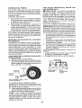
TIRES
• Maintain proper air pressure in all tires
(See PSI on tires).
• Keep tires free of gasoline, oil, or insect
control chemicals
which can harm rubber.
• Avoid stumps, stones, deep ruts, sharp
objects and other hazards that may cause
tire damage.
NOTE: To seal tire punctures and prevent
flat tires due to slow leaks, tire sealant may
be purchased from your local parts dealer.
Tire sealant also prevents tire dry rot and
corrosion_
OPERATOR
PRESENCE
SYSTEM AND
REVERSE OPERATION
SYSTEM (ROS)
CHECK
REVERSE
SYSTEM
For best results mower blades must be sharp.
eplace worn, bent or damaged blades.
CAUTION:
Use only a replacement blade
approved by the manufacturer of your tractor.
Using a blade not approved by the manufacturer of your tractor is hazardous, could
damage your tractor and void your warranty_
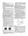
BLADE REMOVAL
1. Raise mower to highest position to allow
access to blades.
NOTE: Protect your hands with gloves and/
or wrap blade with heavy cloth°
2. Remove blade bolt by turning counterclockwise.
3o lnstallnewbladewithstamped"THISStDE
UP" facing deck and mandrel assembly.
IMPORTANT:
To ensure proper assembly,
center hole in blade must align with star on
mandrel assembly°
4, Install and tighten blade bolt securely
(45-55 Ft. Lbs. torque),
IMPORTANT:
Special blade bolt is heat
treated.
MandreB
gaged position.
OPERATOR
PRESENCE
Assembly
° When the engine is running,
by the operator to leave the
first setting the parking brake
off the engine.
• When the engine is running
tachment clutch is engaged,
by the operator to leave the
shut off the engine.
• The attachment clutch should
ate unless the operator is in
ROS "ON" Position
(ROS)
• When the engine is running with the ignition
switch in the engine "ON" position and the
attachment clutch engaged, any attempt
by the operator to shift into reverse should
shut off the engine.
- Whenthe engine is runningwiththe
ignition
switch in the ROS "ON" position and the
attachment clutch engaged, any attempt
by the operator to shift into reverse should
NOT shut off the engine.
BLADE CARE
Be sure operator
presence
and reverse
operation systems are working properly.
If
your tractor does not function as described,
repair the problem immediately.
• The engine should not start unless the
brake pedal is fully depressed,
and the
attachment clutch control is in the disenCHECK
SYSTEM
OPERATION
any attempt
seat without
should shut
Blade
and the atany attempt
seat should
(s_
BATTERY
neveroperthe seat.
Center Hole
-_
Your tractor has a battery charging system
which is sufficientfor
normal use. However,
periodic charging of the battery with an automotive charger wil! extend its life_
• Keep battery and terminals clean.
• Keep battery bolts tight.
• Keep small vent holes opera
• Recharge at 6-10 amperes for 1 hour.
NOTE: The original equipment
battery on
your tractor is maintenance
free. Do not
attempt to open or remove caps or covers.
Adding or checking level of electrolyte
is
not necessary°
Engine "ON" Position
(Normal Operating)
22
TO CLEANBATTERYAND TERMINALS
Corrosionanddirt onthe batteryandterminalscan causethe batteryto "leak"power.
1_ Removeterminalguard°
2. DisconnectBLACK battery cable first
then RED battery cable and remove
batteryfrom tractor,
3. Rinsethebatterywithplainwateranddry.
4. Cleanterminalsandbatterycableends
with wirebrushuntilbright.
5. Coatterminalswithgreaseor petroleum
jelly.
6. Reinstall battery (See "REPLACING
BATTERY'tin the SERVICEAND ADJUSTMENTSsectionof this manual).
TRANSAXLEMAINTENANCE
Thetransmissionfanandcoolingfinsshould
be keptcleanto assurepropercooling.Do
notattempttocleanfanor transmissionwhile
engineis runningor whilethe transmission
is hot,Topreventpossibledamagetoseals,
do not use highpressurewateror steamto
cleantransaxle.
• Inspectcoolingfan to be surefan blades
are intactandclean°
• Inspectcoolingfinsfordirt,grassclippings
andothermaterials,Topreventdamageto
seals,do not use compressedair or high
pressuresprayerto cleancoolingfins.
TRANSAXLEPUMP FLUID
Thetransaxlewassealedatthe factoryand
fluidmaintenanceis not requiredfor the life
of the transaxle.Shouldthe transaxleever
leakor requireservicing,contactyournearest Searsor otherqualifiedservicecenter.
V-BELTS
CheckV-beltsfordeteriorationandwearafter
100hoursofoperationandreplaceif necessary.The beltsare not adjustable_Replace
belts if they beginto slipfromwear,
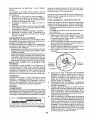
ENGINE
LUBRICATION
Only use high quality detergent oil rated with
API service classification SG-SL. Selectthe
oil's SAE viscosity grade according to your
expected operating temperature.
SAE VISCOSITY
-_ .......
O
_0
-_,0
TEMPERATURE
_.......
-10
_
_
GRADES
_o
0
RANGE ANTICIPATED
6_
_O
B_.............
!o_......
20
_8
40
BEFORE NF.3_TOIL CHANGE
23
NOTE: Although multi-viscosity
oils (5W30,
10W30 etco) improve starting in cold weather,
they wilt result in increased oil consumption
when used above 32°R Check your engine
oil level more frequently to avoid possible
engine damage from running low on oiL
Change the oil after every 50 hours of operation or at least once a year if the tractor is
not used for 50 hours in one year,
Check the crankcase oil level before starting
the engine and after each eight (8) hours
of operation.
Tighten oil fill cap/dipstick
securely each time you check the oil level.
TO CHANGE
ENGINE
OIL
Determine
temperature
range expected
before oil change.
All oil must meet API
service classification
SG-SLo
• Be sure tractor is on level surface.
• Oil will drain more freely when warm.
• Catch oil in a suitable container°
1. Remove oil fill cap/dipstick.
Be careful
not to allow dirt to enter the engine when
changing oil.
2. Remove yellow cap from end of drain
valve and install the drain tube onto the
fitting.
3. Unlock drain valve by pushing inward
slightly and turning counterclockwise.
Oit Drain VaLve
Closed
_
_
and
Locked
f'---_-7_
! _
;,>_."_
_
"_
|
Drain
YellowCap
(_',_
""
Position*"_...._..i,,.'__Tube...
4. To open, pull out on the drain valve.
5. After oil has drained completely, close and
lock the drain valve by pushing inward
and turning clockwise until the pin is in
the locked position as shown.
6. Remove the drain tube and replace the
cap onto the end of the drain valve.
7, Refill enginewith oilthrough oilfill dipstick
tube. Pour slowly, Do not overfill.
For
approximate
capacity see "PRODUCT
SPECtFICATIONS"section
ofthis manual.
8. Use gauge on oil fill cap/dipstick
for
checking level.
Insert dipstick into the
tube and rest the 0i! fill cap on the tube.
Do not thread the cap onto the tube when
taking reading
Keep oil at "FULL.' line
on dipstick. Tighten cap onto the tube
securely when finished,
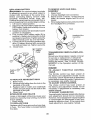
AIR FILTER
CLEAN
Your engine will not run properly using a
dirty air filter. Service paper cartridge ever,/
two months or every 25 hours of operation,
whichever occurs first.
Service paper cartridge more often under
dusty conditions°
Replace the paper cartridge ann ually, or after
ever,/100 hours of operation°
Air screen must be kept free of dirt and chaff
to prevent engine damage from overheating_
Clean with a wire brush or compressed air to
remove dirt and stubborn dried gum fibers.
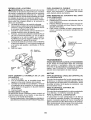
TO SERVICE
CLEAN
AIR SCREEN
AIR INTAKE/COOLING
AREAS
To ensure proper cooling, make sure the
grass screen, cooling fins, and other external surfaces of the engine are kept clean
at all times.
Every !00 hours of operation (more often
under extremely
dusty, dirty conditions),
remove the blower housing and other cooling
shrouds_ Clean the cooling fins and external
surfaces as necessary. Make su re the cooling
shrouds are reinstalled.
CARTRIDGE
, Replace a dirty, bent, or damaged
car_
tridge, Handle new cartridge carefully; do
not use if the rubber seal is damaged.
NOTE:
Do not wash the paper cartridge
or use pressurized air, as this will damage
the cartridge.
1. Open door (A) on the blower housing to
access the air cleaner element (B).
NOTE:
Operatingthe
engine with a blocked
grass screen, dirty or plugged cooling fins,
and/or cooling shrouds removed will cause
engine damage due to overheating.
MUFFLER
Inspect and replace corroded muffler and
spark arrester (if equipped) as it could create
a fire hazard and/or damage.
SPARK
2.
Unhook the latch
element°
(C) and remove
PLUG(S)
Replace spark plug(s) at the beginning of
each mowing season or after every 100
hours of operation, whichever occurs first.
Spark plug type and gap setting are shown
in "PRODUCT
SPECIFICATIONS"
section
of this manual
the
IN-LINE
FUEL FILTER
The fuel filter should be replaced once each
season. If fuel filter becomes clogged, obstructing fuel flow to carbureto r, replacement
is required.
1. With engine cool, remove filter and plug
fuel line sections.
2. Place new fuel filter in position in fuel line
with arrow pointing towards carburetor.
3. Be sure there are no fuel line leaks and
clamps are properly positioned.
4. immediatelywipe
up anyspilled gasoline.
3. Gently tap the paper element to dislodge
dirt.
4. Clean all air cleaner components
of any
accumulated
dirt or foreign material.
Prevent any dirt from entering the throat
of carburetor.
5. Install cleaned or new element on the
base and secure with latch.
6. Close and latch the door.
Clam_amp
Fuel Filter ------4-_j/rJ_J
24
CLEANING
•
Clean engine, battery, seat, finish, etc.
of all foreign matter.
Clean debris from steering plate°
Debris can restrict clutch/brake
pedal
shaft movement, causing belt slip and
loss of drive.
°
,_ CAUTION:
Avoid
movable
parts
all pinch
points
and
Clutch/brake pedal
Clean
4.
Pull back the lock collar of the nozzle
adapter and push the adapter onto the
deck washout port at the left end of the
mower deck. Release the lock collar to
lock the adapter on the nozzle.
IMPORTANT:
Tug hose ensuring connection is secure.
Steering
Steering System, Dash,
Pinch
\
t C_ UTION:
Fender and Mower Not Shown
Points
Keep finished surfaces and wheels
free of all gasoline, oil, etc.
.
Protect painted surfaces with automotive type wax.
We do not recommend using a garden hose
or pressure washer to clean your tractor
unless the engine and transmission
are
covered to keep water out. Water in engine
or transmission
will shorten the useful life of
your tractor. Use compressed
air or a leaf
blower to remove grass, leaves and trash
from tractor and mower.
5.
Turn the water on
6_
While sitting in the operator's position
on the tractor, re-start the engine and
place the throttle lever in the Fast "._"
position.
•
DECK WASHOUT
IMPORTANT:
Recheck
the
certain the area is clear,,
1.
Drive the tractor to a level, clear spot
on your lawn, near enough to a water
spigot for your garden hose to reach.
IMPORTANT:
Make certain the tractor's
discharge chute is directed AWAY from your
house, garage, parked cars, etc. Remove
bagger chute or mulch cover if attached.
2.
Make sure the attachment clutch control
is in the "DISENGAGED"
position, set
the parking brake, and stop the engine°
3.
Thread the nozzle adapter (packaged
with your tractor's Operator's Manual)
onto the end of your garden hose°
making
7.
Move the tractor's attachment
clutch
control to the "ENGAGED"
position.
Remain
in the operator's
position
with the cutting deck engaged until the
deck is cleaned.
8o
Move the tractor's attachment
clutch
control to the "DISENGAGED"
position, Turn the ignition key to the STOP
position to turn the tractor's engine off.
Turn the water off.
9.
Pull back the lock collar of the nozzle
adapter to disconnect the adapter from
the nozzle washout port,
10.
Move the tractor to a dry area, preferably a concrete or paved area. Place
the attachment
clutch control in the
"ENGAGED" position to remove excess
water and to help dry before putting the
tractor away°
PORT
"Your tractor's
deck is equipped
with a
washout port on its surface as part of its
deck wash system. It should be utilized after each use.
area
_WARNING:
A broken or missing washout
fitting could expose you or others to thrown
objects from contact with the blade.
" Replace broken or missing washout fitting
immediately, prior to using mower again.
• Plug any holes in mower with bolts and
locknuts.
25
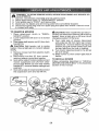
_
ARNING: TO AVOID SERIOUS INJURY, BEFORE PERFORMING ANY SERVICE OR
ADJUSTMENTS:
1_
3,
4,
5,
6,
TO
Depress clutch/brake
pedal fully and set parking brake.
Place attachment clutch in "DISENGAGED"
position,
Turn ignition key to "STOP" and remove key,
Make sure the blades and all moving parts have completely stopped,
Disconnect spark plug wire from spark plug and place wire where it cannot come
in contact with plug,
REMOVE
MOWER
1_ Place attachment
GAGED" position.
2. Lower attachment
CAUTION:
clutch
in "DISEN-
nected, the attachment lift lever will be spring
loaded° Have a tight grip on lift lever when
changing position of the lever.
lift lever to its lowest
position.
3. Disengage belt tension rod (K) from lock
bracket (L).
_, CAUTION:
Belt tension rod is spring
loaded. Have a tight grip on rod and release
slowly.
4. Remove mower belt from electric clutch
5.
6.
7.
B.
From right side of mower, disconnect
anti-sway bar (S) from right rear mower
bracket (D) - remove retainer spring and
washer and pull mower toward you until
the bar falls from the hole in bracket.
9, "t_,_rntractor steering wheel to the left as
far as it will go.
10oSlide mower out from under right side of
tractor.
pulley (M).
Disconnect
front link (E) from mower remove retainer spring and washer.
Go to either side of mower and disconnect
mower suspension
arm (A) from chassis and rear lift link (C) from rear mower
bracket (D) * remove retainer springs and
washers.
Go to other side of mower and disconnect
the suspension
After rear lift links are discon-
TO INSTALL
MOWER
Follow procedure
described
in "INSTALL
MOWER AND DRIVE BELT" in the Assembly
section of this manual.
arm and rear lift link.
26
TO LEVEL. MOWER
Make sure tires are properly inflated to the
PSI shown on tires. If tires are over or under
inflated, it may affect the appearance of your
lawn and lead you to think the mower is not
adjusted properly.
VISUAL
SIDE-TO-SIDE
4_ If adjustment
is necessary, see steps 2
and 3 in Visual Adjustment
instructions
above.
5. Recheck measurements, adjust if necessary until both sides are equal.
FRONT-TO-BACK
ADJUSTMENT
IMPORTANT:
Deck must be level sideto-side.
To obtain the best cutting results, the mower
blades should be adjusted so the front tip is
1/8" to 1/2" lower than the rear tip when the
mower is in its highest position.
CAUTION:
Blades are sharp. Protect
your hands with gloves and/or wrap blade
with heavy cloth.
• Raise mower to highest position.
, Position any blade so the tip is pointing
straight forward. Measure distance (B) to
the ground at front and rear tip of the blade.
ADJUSTMENT
I.
With all tires properly inflated and if your
lawn appears unevenly cut, determine
which side of mower is cutting lower.
NOTE: As desired, you can raise the low
side of mower or lower the high side°
2. Go to side of mower you wish to adjust,
3. With a 3/4" or adjustable
wrench, turn
lift link adjustment
nut (A) to the left to
lower the mower, or, to the right to raise
the mower.
, If front tip of blade is not 1/8" to 1/2" lower
than the rear tip, go to the front of tractor.
• With an I1/16"
or adjustable
wrench,
loosen jam nut A several turns to clear
adjustment
nut B_
• With a 3/4" or adjustable
wrench, turn
front link adjustment
nut (B) clockwise
(ltighten) to raise the front of mower, or,
counterclockwise
(loosen) to lower the
front mower,
Turn nut left
to lower mower
Turn nut rig
to raise mower
NOTE: Each full turn of adjustment
nut will
change mower height about 3/16".
4. Test your adjustment
by mowing some
uncut grass and visually checking the
appearance.
Readjust, if necessary, until
you are satisfied with the results.
PRECISION
SIDE-TO-SIDE
ADJUSTMENT
1. With all tires properly inflated, parktractor
on level ground or driveway.
_1_ CAUTION:
Blades are sharp. Protect
your hands with gloves and/or wrap blade
with heavy cloth.
2, Raise mower to its highest position.
3. At both sides of mower, position blade at
side and measure the distance (A) from
bottom edge of blade to the ground. The
distance should be the same on both sides.
Tighten adjusL nut
B to raise mower
Loosen adjust
nut B to lower
mower
Loosen jam nut A first
NOTE: Each full turn of the adjustment nut
will change mower height about 1/8".
• Recheck measurements,
adjust if necessary until front tip of blade is 1/8" to 1/2"
lower than the rear tip°
• Hold adjustmentnut
in position with wrench
and tighten jam nut securely against adjustment nut.
A;
27
TO REPLACE
MOWER
MOWER
DRIVE
DRIVE
BELT
NOTE: Observe
entire motion drive belt and
position of all belt guides and keepers,
2. Disconnect clutch wire harness (A).
3. Remove anti-rotation link (B) on right side
of tractor.
4. Remove beltfrom stationary idler (C) and
clutching idler (D).
5. Pull belt slack toward rear of tractor,
Carefully
remove
belt upwards
from
transmission
input pulley and over cooling fan blades (F).
6. Remove
belt downward
from engine
pulley and around electric clutch (G).
7. Slide belt toward rear of tractor, off the
steering plate (H) and remove from tractor,,
BELT REMOVAL
1,
Park tractor on a level surface, Engage
parking brake,
2. Lower attachment
lift lever to its lowest
position°
3, Disengage belt tension rod (K) from lock
bracket (L)o
CAUTION: Belttension rod is spring loaded. Have a firm grip on rod and release slowly_
4. Remove screws (P) from R.H_ and L.H.
mandrel covers and remove covers (Q).
5. Remove any dirt or grass clippings which
may have accumulated around mandrels
and entire upper deck surface.
6. Remove belt from electric clutch pulley
(M), both mandrel pulleys (R) and allidler
pulleys (S)o
\
MOWER
DRIVE
BELT INSTALLATION
1. Install belt around both mandrel pulleys
(R) and around idler pulleys (S) as shown,
2, Install belt onto electric clutch pulley (M).
IMPORTANT:
Check belt for proper routing
in all mower pulley grooves.
3. Reassemble R,H, and L,H, mandrel covers (Q). Securely tighten all screws.
4, Engage bell tension rod (K) on locking
bracket (L).
CAUTION; Belt tension rod is spring load _
ed, Have atightgrip on rod and engage slowly.
5. Raise attb,chment lift lever to highest
position.
TO REPLACE
MOTION
DRIVE
1o Remove
MOWER"
!.
2.
4.
5.
6.
7.
-
8.
mower (See "TO REMOVE
in this section of manual).
28
-
Install new belt from tractor rear to front,
over the steering plate (H) and above
clutch brake pedal shaft (J)o
Pullbelttowardfrontoftractorand
rollbelt
around electric clutch and onto engine
pulley (G).
3. Pull belt toward rear of tractor. Carefully
work belt down around transmission
BELT
Park the tractor on level surface.
Engage
parking brake.
For assistance,
there is a
belt installation guide decal on bottom side
of left footresL
BELT REMOVAL
BELT INSTALLATION
cooling fan and onto the input pulley (F),
Be sure belt is inside the belt keeper.
Install belt through stationary
idler (C)
and clutching idler (D).
Reinstall anti-rotation
link (B) on right
side of tractor, Tighten securely,
Reconnect clutch harness (A).
Make sure belt is in all pulley grooves
and inside all belt guides and keepers,
Install mower (See "TO INSTALL MOWER" in this section of manual).
TO CHECK
TO START
TERY
BRAKE
If tractor requires more than five (5) feet to
stop at highest speed in highest gear on a
level, dry concrete or paved surface, then
brake must be serviced°
held in the disengaged
position.
The rear wheels must lock and skid when
you try' to manually push the tractor forward_
If the rear wheels rotate, then the brake
needs to be serviced. Contact a Sears or
service
WHEEL
center°
FOR REPAIRS
1. Block up axle securely.
2, Remove axle cover, retaining ring and
washers to allow wheel removal (rear
wheels have a square key - Do not lose).
3. Repair tire and reassemble.
NOTE: On rearwheels only: align grooves in
rear wheel hub and axle, Insert square key_
4o Replace washers and snap retaining ring
securely in axle groove°
5o Replace axle cover,
NOTE: To seal tire punctures and prevent
flat tires due to slow leaks, purchase and
use tire sealant from Sears. Tire sealant also
prevents tire dry rot and corrosion.
TO REMOVE
ORDER
CABLES,
Retaining
Ring
'_Square
Key (Rear
Wheel Only)
29
REVERSE
to BLACK cable first from chassis and then
from the fully charged battery.
2. RED cable last from both batteries_
Weak or Dead
Battery
Washers
Axle Cover
BAT-
TO ATTACH JUMPER CABLES
1. Connectone
end ofthe RED cabteto the
POSITIVE (+) terminal of each battery(AB), taking care notto short against tractor
chassis.
2, Connect one end of the BLACK cable
to the NEGATIVE (-) terminal (C) of fully
charged battery.
3, Connect the other end of the BLACK
cable (D) to good chassis ground, away
from fuel tank and battery,
FRONT WHEEL TOE-IN/CAMBER
Your new tractor front wheel toe-in and camber is set at the factory and is normal° The
front wheeltoe-in and camber are not adjustable. If damage has occurred to affect the
factory' set front wheeltoe-in
or camber, contact a Sears or other qualified service center.
TO REMOVE
WITH A WEAK
_WARNING;
Lead-acid batteries generate explosive gases_ Keep sparks, flame
and smoking materials away from batteries.
Always wear eye protection when around
batteries.
If your battery is too weak to start the engine, it
should be recharged, (See "BATTERY" in the
MAINTENANCE
section of this manual).
If "jumper cables" are used for emergency
starting, follow this procedure:
IMPORTANT:
Your tractor is equipped with
a 12volt system. The other vehicle must also
be a 12 volt system. Do not use your tractor
battery to start other vehicles.
Y'ou may also check brake by:
1o Park tractor on a level, dr:/concrete
or
paved surface, depress brake pedal all
the way down and engage parking brake.
2o Disengage
transmission
by placing
freewheel
control in "transmission
disengaged" position. Pull freewheel control
out and into the slot and release so it is
other qualified
ENGINE
Fully Charged
Battery
REPLACING
BATTERY
_,WARNING:
Do not short battery terminals
by allowing a wrench or any other object to
contact both terminals at the same time.
Before connecting
battery, remove metal
bracelets,
wristwatch
bands, rings, etco
Positive terminal must be connected first to
prevent sparking from accidental grounding.
1. Lift hood to raised position.
2o Disconnect BLACKbattery
cable (A) then
RED battery cable and carefully remove
battery from tractor.
3_ install new battery with terminals in same
position as old battery.
4. First connect RED battery cable (B) to
positive (+) battery terminal with hex bolt
and keps nut as shown.Tighten
securely.
Slide terminal cover (C) over terminal,
5, ConnectBLACKgroundingcabteto
negative (-) battery terminal with remaining
hex bolt and keps nut. Tighten securely_
6. Close hood.
_ _ Negative
(Black)
Cable
TO REMOVE
ASSEMBLY
HOOD
AND GRILL
1. Raise hood.
2. Unsnap headlight wire connector.
3o Stand in front of tractor. Grasp hood at
sides, tilt toward engine and lift off of
tractor.
4. Whenreplacinghood,
besuretoreconnect
the headlight wire connector.
Hood
Headlight Wire
Connector
TRANSMISSION
MENT
REMOVAL/REPLACE-
Should your transmission
require removal
for service or replacement,
it should be
purged after reinstallation and before operating the tractor. See "PURGE TRANSMISSION" in the Operation section of this
manual.
ENGINE
Positive
(Red)
Cable
TO REPLACE
HEADLIGHT
BULB
1o Raise hood.
2. Remove bulb holder from the hole inthe
backside of the grill.
Replace bulb in holder and install bulb
holder securely back into the hole in the
backside of the grill.
4o Close hood.
INTERLOCKS
AND RELAYS
3.
Loose or damaged wiring may cause your
tractor to run poorly, stop running, or prevent
it from starting.
, Check wiring.
TO REPLACE
FUSE
TO ADJUST
CABLE
THROTTLE
CONTROL
The throttle control has been preset at
the factory and adjustment
should not be
necessary Check adjustment as described
below before loosening cable. If adjustment
is necessary, see engine manual.
TO ADJUST CHOKE CONTROL
The choke control
has been preset at
the factory and adjustment
should not be
necessary. If adjustment is necessary, see
engine manual.
TO ADJUST CARBURETOR
Your carburetor has been preset atthe factory
and adjustment
should not be necessary.
However, minor adjustment may be required
to compensate for differences in fuel, temperature, altitude or Ioado If the engine does
need adjustment, see engine manual.
Replace with 30 amp automotive-type
plugin fuse. The fuse holder is located behind
the dash.
3O
Immediately prepare your tractor for storage
at the end of the season or if the tractor will
ENGINE
FUEL SYSTEM
be used for 30 days or more.
ARNING:
Never store the tractor with
gasoline in the tank inside a building where
fumes may reach an open flame or spark.
Allow the engine to cool before storing in
any enclosure.
TRACTOR
Remove
mower
from
tractor
for
IMPORTANT:
It is important to prevent
gum deposits from forming in essential fuel
system parts such as carburetor, fuel hose,
or tank during storage. Also, alcohol blended
fuels (called gasohol or using ethanol or
methanol) can attract moisture which leads
to separation and formation of acids during
storage. Acidic gas can damage the fuel
system of an engine while in storage.
• Empty the fuel tank by starting the engine
and letting it run until the fuel lines and
carburetor are empty.
• Never use engine or carburetor
cleaner
products in the fuel tank or permanent
damage may occur.
- Use fresh fuel next season.
NOTE:
Fuel stabilizer
is an acceptable
alternative
in minimizing
the formation
of
fuel gum deposits
during storage.
Add
stabilizer to gasoline in fuel tank or storage
container. Always follow the mix ratio found
on stabilizer container.
Run engine at least
10 minutes after adding stabilizer to allow
the stabilizer to reach the carburetor. Do not
winter
storage. When mower is to be stored for a
period of time, clean it thoroughly, remove
all dirt, grease, leaves, etc. Store in a clean,
dry area,
1. Clean entire tractor (See "CLEANING"
in the Maintenance
section
of this
manual).
2. inspect and replace belts, if necessary
(See belt replacement
instructions in the
Service and Adjustments
section of this
manual),
3. Lubricate as shown in the Maintenance
section of this manual.
4, Be sure that all nuts, bolts and screws
are securely fastene&
Inspect moving
parts for damage, breakage and wear_
Replace if necessary.
5. Touch up all rusted or chipped paint
surfaces; sand lightly before painting,
empty the gas tank and carburetor
fuel stabilizer.
ENGINE OIL
BATTERY
• Fully charge the battery for storage.
• After a period of time in storage, battery
may require recharging.
• To help prevent
corrosion
and power
leakage during long periods of storage,
battery cables should be disconnected
and battery cleaned thoroughly
(see "TO
CLEAN BATTERY AND TERMINALS"
in
the Maintenance
section of this manual)°
, After cleaning, leave cables disconnected
and place cables where they cannot come
in contact with battery terminals.
• If battery is removed
from tractor for
storage, do not store battery directly on
concrete or damp surfaces.
if using
Drain oil (with engine warm) and replace
with clean engine oil. (See "ENGINE" in the
Maintenance
section of this manual).
CYLINDER(S)
1, Remove spark plug(s),
2_ Pour one ounce of oil through spark plug
hole(s) into cylinder(s).
3. "Parn ignition key to start position for a
few seconds to distribute oil.
4. Replace with new spark plug(s).
OTHER
° Do not store gasoline from one season to
another.
• Replace your gasoline can if your can starts
to rust, Rust and/or dirt in your gasoline
wilt cause problems°
• If possible, store your tractor indoors and
cover it to give protection from dust and dirt°
• Cover your tractor with a suitable protective cover that does not retain moisture°
Do not use plastic° Plastic cannot breathe
which allows condensation to form and will
cause your tractor to rust.
IMPORTANT:
Never cover
engine
3!
and exhaust
tractor
while
areas are still warm.
TROUBLESHOOTING
CHART:
See appropriate section
in manual unless directed to Sears service
-PROBLEM
center
i
i CORRECTI!ON
:CAUSE
i
Will
not start
Hard to start
Engine will not
turn over
1
Out of fuel.
1
2
Engine not "CHOKED" properly.
2_ See "TO START ENGINE" in
Operation section.
3
Engine flooded.
3
Wait several minutes before
attempting to start,,
4
Bad spark plug.
4
Replace spark plug.
5
Dirty air filter.
5
Clean/replace
6
Dirty fuel filter,
6
Replace fuel filter.
7
Water in fuel.
7
Empty fuel tank and carburetor,
refill tank with fresh gasoline and
replace fuel filtec
8
Loose or damaged wiring.
8
Check all wiring.
9
Carburetor out of adjustment,
9
See "To Adjust Carburetor" in
Service and Adjustments section.
t0
Engine valves out of adjustment.
t0 Contact a Sears or other qualified
I
Dirty air filter.,
1
Clean!replace
2
Bad spark plug.
2
Replace spark plug.
3
Weak or dead battery_
3
Recharge or replace battery,,
4
Dirty fue! filter_
4
Replace fuel filter.
5
Stale or dirty fuel.
5
Empty fuel tank and refill tank with
fresh, clean gasoline.
6
Loose or damaged wiring,
6
Check all wiring°
7
Carburetor out of adjustment,
7
See "To Adjust Carburetor" in
Service and Adjustments section.
8
Engine valves out of adjustment.
8
Contact a Sears or other qualified
service center°
1
Clutch/brake
t
Depress clutch/brake
2
Attachment
2
Disengage
3
Weak or dead battery.
3
Recharge or replace battery.
4
Blown fuse.
4
Replace fuse.
5
Corroded battery terminals°
5
Clean battery terminals.
6
Loose or damaged wiring,
6
Check all wiring.
7
Faulty ignition switch.
7
Check/replace
ignition switch,
8
Faulty solenoid or starter.
8
Check/replace
solenoid or starter,
9
Faulty operator presence
switch(es).
9
Contact a Sears or other qualified
service, center.
pedalnot depressedclutch is engaged.
32
Fill fuel tank°
air filter.
service center.
air filter,
pedal,,
attachment
clutch.
TROUBLESHOOTING CHART:
See appropriate section in manual unless directed to Sears service center
CAUSE
PROBLEM
Engine clicks but
will not start
Loss of power
Excessive vibration
Engine continues
to
run when operator
leaves seat with attachrnent clutch engaged
CORRECTION
1
Weak or dead battery.
1
Recharge or replace battery,
2
Corroded battery terminals,
2
Clean battery terminals_
3
Loose or damaged
3
Check all wiring,
4
Faulty solenoid or starter,
4
Check/replace
1
Cutting too much grass/too
1
Raise culling height/reducespeed,
2
Throttle in "CHOKE" position.
2
Adjust throttle control.
3
Build-up of grass, leaves and
trash under mower,
3
Clean underside of mower
housing.,
4
Dirty air filter,
4
Clean/replace
5
Low oil level/dirty
5
Check oiflevel/change
6
Faulty spark plugo
6
Clean & regaporchangesparkplug
7
Dirty fuel filter.,
7
Replace fuel filter,,
8
Stale or dirty fuel,
8
Empty fuel tank and refill tank with
fresh, clean gasoline,
Water in fuelo
9
Empty fuel tank and carburetor,
refill tank witll fresh gasoline and
replace fuel filler,
wiring°
fast,,
oil,
solenoid or starterr
air filter.
oil,
it0
Spark plug wire loose_
10
Connect & tighten spark plug wire,
ill
Dirty engine air screen/fins,
11
Clean engine air screentfins.,
112
Dirty/clogged
12
Clean/replace
113
Loose or damaged wiring°
13
Check all wiring.
14
Carburetor out of adjustment.
14
See "To Adjust Carburetor" in
Service and Adjustments section,
_15
Engine valves out of adjustment,
15
Contact a Sears or other qualified
service center,,
muffler.
muffler.
1
Worn, bent or loose blade.
1
Replace blade. Tighten blade bolt,
2
Bent blade mandrel,.
2
Contact a Sears or other qualified
service center.
3
Loose/damaged
3
Tighten loose part(s)
Replace damaged parts.
1
Faulty operator-safety
control system,
1
Check wiring, switches and
connections, If not corrected,
contact a Sears or other
part(s).
33
presence
TROUBLESHOOTING
CHART:
See appropriate section in manual unless directed to Sears service center
PROBLEM
Poor cut - uneven
cutting
Mower blades wilt
not rotate
Poor grass
discharge
1
Worn, bent or loose blade.,
Replace blade_ Tighten blade bo]t,
2
Mower deck not level.
Level mower deck.
3
Buildup of grass, leaves, and
trash under mower
Clean underside of mower
housing..
4
Bent blade mandrel.
Contact a Sears or other
qualified service center.
5
Clogged mower deck vent from
build-up of grass, leaves, and
trash around mandrels_
Clean around mandrels to
open vent holes.
1
Obstruction
Remove obstruction.
2
Worn!damaged
3
Frozen idler pulley,,
Replace idler pulley_
4
Frozen blade mandrel.
Contact a Sears or other
qualified service center.
1
Engine speed too slow.
Place throttle control in "FAST"
position.
2
Travel speed too fast,
Shift to slower speed,,
3
Wet grass.
Allow grass to dry before mowing.
4
Mower deck not level
Level mower deck,
5
Low/uneven
Check tires for proper PSI.
6
Worn, bent or loose blade°
Replace/sharpen
blade bolt,
Buildup of grass, leaves and
trash under mower..
Clean underside of mower
housing,,
8
Mower drive belt worn,
Replace mower drive belt.,
9
Blades improperly installed.
Reinstall blades sharp edge down
10
Improper blades used,
Replace with blades listed in
this manual
'11
Clogged mower deck vent holes
from buildup of grass, leaves, and
trash around mandrels°
Clean around mandrels to
open vent holes,
'"
Headlight(s) not
working
(if so equipped)
'ION
CAUSE
in clutch mechanism°
mower drive belt
tire air pressure
Replace mower drive belt.
blade° Tighten
i
1 : Light switch is "OFF".
Turn light switch "ON",.
2!
Bulb(s) or lamp(s) burned out.
Replace bulb(s) or famp(s)_
3
Faulty light switch.
Check/replace
Loose or damaged wiring_
Check wiring and connections.
Blown fuse_
Replace fuse,,
4
I
5z
34
light switch,,
TROUBLESHOOTING
CHART:
See appropriate section in manual unless directed to Sears service center
i
PROBLEM
CORRECTION
CAUSE
li
Battery will not
charge
Bad battery celt(s),
1
Replace battery,,
Poor cable connections,
2
Check!clean
3!
Faulty regulator (if so equipped),
3
Replace regulator.
4i
Faulty alternator,
4
Replace alternator
li
Freewheel control in
"DISENGAGED" position.,
1
Place freewheel control in
"ENGAGED" position°
2i
Debris on steering plate (if
equipped),,
2
See "CLEANING" in the
maintenance section_
3_
Motion drive belt worn, damaged,
or broken,
3
Replace motion drive belt,,
4
Purge transmission°
5
Install axle key at rear wheel See
"TO REMOVE WHEEL" in the
Service and Adjustments section_
2!
i
i
Loss of drive
all connections,
i
4! Air trapped in transmission
during
shipment or servicing,
5_ Axle key missing,,
11 Engine
throttle control not sel 1
between half and full speed (fast)
position before stopping engine
Engine "backfires"
when turninq
engine "OFF"
Reverse operation system (ROS)
is not "ON" while mower or other
attachment is engaged°
Engine dies when
tractor is shifted
into reverse
Move throttle control between
half and full speed (fast) position
before stopping engine,
1 Turn ignition key to ROS "ON"
position, See Operation section°
iii
NEED MORE HELP?
i_i!il
You_t find the answer and more on managemyhome.com
• Find this and all your other product
¸
- for free!
!!i_
manuals online.
• Get answers from our team of home experts°
• Get a personalized
maintenance
plan for your home.
ii:::i
• Find information
manage
and tools
to help with
home projects,
home
_i _
_:::L
¸
brought to you by Sears
35
SUGGESTED
GUIDE FOR SIGHTING SLOPES FOR SAFE OPERATION
ONLY RIDE UP AND DOWN HILL,
NOT ACROSS HILL
o_
15 DEGREES
MAX.
WARNING: To avoid serious injury, operate your tractor up and
down
face of
slopes,
never across
the face.
Do nottomow
slopes the
greater
than
15 degrees.
Make turns
gradually
prevent
tipping or loss of control. Exercise extreme caution when
changing direction on slopes,
IHL.L
1. Fold this page along dotted line indicated above.
2, Hold page before you so that its left edge is vertically parallel to a tree
trunk or other upright structure.
3. Sight across the fold in the direction of hill slope you want to measure.
4. Compare the angle of the fold with the slope of the hill.
Garantia ..........................................................
37
Reglas de Seguddad ...................................... 38
Especificaciones del Producto ....................... 40
MontajeiPre Operaci6n ......................................43
Operaci6n ..............................................................
48
Mantenimiento ............................................... 56
GARANTIA
COMPLETA
Programa de Mantenimiento ......................... 56
Servicio y Ajustes ............................................. 61
Almacenamiento ............................................... 66
ldentificaci6n de Problemas ......................................
67
Servicio Sears .....................................Contratapa
DE CRAFTSMAN
DOS AI_,IOS PARA EL EQUIPO
TRACTOR
Cuando se opera y mantiene de acuerdo con todas las instrucciones que se suministran, si este
equipo tractor falla debido a un defecto de material o mano de obra dentro de los dos aflos posteriores
a la fecha de compra, llame al tet_fono 1-800-4-MY-HOME® para solicitar Ia reparaci6n gratuita°
Adem&s, cuando se opera y mantiene de acuerdo con todas las instrucciones que se suministran,
la garantia tambi6n cubre defectos de material y mano de obra del bastidor y del eje delantero por
cinco aSos a partir de la fecha de compra,
Esta garantia cubre UNICAMENTE defectos de material y mano de obra. Sears NO
pagara:
•
•
•
•
•
•
,
•
Componentes de desgaste que se desgasten durante et uso normal, incluso (pero sin limitarse
a ello) hojas, bujias, filtros de aire, correas y filtros de aceite_
Servicios de mantenimiento est&ndar, cambios de aceite o afinaciones.
Reemplazo o reparaciSn de neum&ticos pot pinchazos causados por objetos externos como
clavos, espinas, tocones o vidrios.
Reemplazo o reparaciSn de neum&ticos o ruedas por el desgaste normal, accidentes o por
operac[6n o mantenimiento incorrectoso
Reparaciones necesarias por abuso del operador, incluso (pero sin limitarse a ello) dafios causados
pot remolcar objetos que superen la capacidad del equipo tractor, chocar contra objetos que
doblen el bastidor o el ciguefiat o por sobrepasar la vetocidad del motor.
Reparaciones necesarias pot negligencia det operador, inctuso (pero sin limitarse a ello) daflos
el#ctricos y mec&nicos causados pot el almacenamiento incorrecto, por no usar el grado y la
cantidad correctos de aceite de motor, por no mantener del muelle libre de residuos inflamables
o por no mantener el equipo tractor de acuerdo con ras fnstrucciones que contiene el manual del
operador,
Limpieza o reparaciones del motor (sistema de combustible) cuando se determina que se us6
combustible contaminado y oxidado (sarro). En general, el combustible debe usarse dentro de
los 30 dias posteriores a su compra..
Deterioro y desgaste normal de los acabados exteriores o sustituci6n de rStulos de productos.
Toda cobertura de garantia del equipo tractor y la bateria queda nula si este producto se utiliza
alguna vez con fines comerciales o de atquiler_
Esta garantia se aplica sSIo mientras el producto se encuentre dentro de los EE,UU
Esta garantia le otorga derechos legales especificos, y usted tambi_n puede tener otros derechos
que varian de un estado a otro o
Sears,
Roebuck
and Co., Hoffman
Estates,
37
IL 60179
_PELIGRO:
Esta Maquina cortadora es capaz de amputar las manosy los pies y de lanzar
objetos, sl no se observan las lnstrucclones de seguridad sigutentes se pueden producir
lesiones graves o la muerte.
• No maneje la m&quina si no tiene la trampa
_ADVERTENCIA:
Siempre desconecte el afampara c6sped completa, la canaleta de descarga
bre de la bujia y p6ngalo donde no pueda entrar
u otros dispositivos de seguridad en su lugar
en contacto con la bujia, para evitar et arranque
yen funcionamiento,.
por accidente, durante ta preparaci6n, el trans- Ralentizar antes de girar.
porte, el ajuste o cuando se hacen reparaciones.
• Nunca dejar una m_.quina encendida sin vigilanciao Apagar siempre tas cuchillas, poner el
_DVERTENCIA:
No avance cuestaabajo a punfreno de estacionamiento, parar el motor, y
to muerto ya que podria perder el control del tractor°
quitar las Itaves antes de bajar.
• Desenganche
las hojas cuando no est_
_ADVERTENClA;
Remolque solamente los
cortando c_.sped. Apague el motor y espere
accesorios recomendados y conformes a las
hasta que todas las partes se detengan por
caracteristicas indicadas por el fabricante de su
completo antes de limpiar la m_.quina, retirar
tractor, Tenga cuidado y prudencia al utilizar el
la trampa para c6sped o destapar la canaleta
tractor. Cuando se encuentre en un declive, oper
de descarga_
utilizando exclusivamente la velocidad m&s bajao
• Hacer funcionar la m_quina s6to con la luz del
En caso de un declive una carga excesiva podria
dia o luz artificia! buena.
resultar peligrosa.
Los neum_,ticos pueden
•
No hacer funcionar la m&quina estando bajo
perder la tracci6n con el suelo y hacerle perder
los efectos de atcohol o droga.
el control de su tractor.
• Porter atenci6n al tr_.fico cuando se opera
_DVERTENCIA:
El tubo de escape del motor,
cerca de caltes o se cruzan.
• Poner la m&xima atenci6n al cargar o descaralgunos de sus constituyentes y algunos componentes del vehiculo contienen o desprenden
gar la m&quina en una caravana o cami6n_
productos quimicos conocidos en el Estado de
• Llevar siempre gafas de protecci6n cuando se
California como causa de c&ncer y defectos al
hace funcionar la m&quinao
nacimiento u otros daSos reproductivos_
• Los datos indican que los operadores a partir
de los 60 afios est&n afectados por un gran
_,DVERTENCIA:
Los bornes, terminales y acporcentaje de heridas relativas a la conducci6n
cesorios relativos de la bateria contienen plomo
del cortac6spe& Estos operadores tendrian
o compuestos de ptomo, productos quimicos
que evatuar su habilidad de hacer funcionar
conocidos en el Estado de California como causa
el cortac6sped de modo Io bastante seguro
de c&ncer y defectos al nacimiento u otros daSos
para proteger a si mismos y a otras personas
reproductivos. Lavar tas manos despu_s de
de heridas graves.
manipularlos.
• Seguir las recomendaciones del fabricante
para los pesos y contrapesos de las ruedas°
I. FUNCIONAMIENTO
GENERAL
• Mantener la m&quina fibre de hierba, hojas
• Leer, entender y seguir todas las instrucciones
u otros escombros que pueden tocar el
sobre la m&quina yen el manual antes de
tubo de escape / partes del motor cafientes
empezar.
y quemarse. No permitir que el puente det
• No poner las manos o los pies cerca de partes
cortac6sped cargue hojas u otros residuos
giratorias o debajo de fa m&quina, mantener
que pueden causar acumulaciones. Limpiar
siempre limpia la abertura de descarga.
toda salpicadura de aceite o carburante antes
. Permitir el funcionamiento de la m&quina s61o
de hacer operaciones sobre la m&quina o
a adultos que tengan familiaridad con las
guardarla. Dejarla enfriar antes de guardarla.
instrucciones.
II. FUNClONAMIENTO
EN PENDIENTES
• Limpiar el _,rea de objetos como piedras,
Las
pendientes
son
el
mayor
factor de accijuguetes, cables, etco que pueden ser recogidentes
relativos
a
la
p6rdida
de
control
y vuelco,
dos y disparados con las cuchillas.
que pueden causar severas heridas o muerte.
• Asegurarse de que el &rea est6 libre de otras
El funcionamiento en pendientes requiere una
personas antes de ponerla en marcha. Parar
atenci6n
extra. Si no es posible hacer marcha
la m&quina si alguien entra en el &tea.
atr&s en una pendiente o si te sientes incomodo,
• Nunca llevar pasajeroso
no la cortes°
• No cortar marcha atr&s al no ser absolu. Cortar hacia arriba y abajo de una pendiente,
tamente necesario. Mirar siempre abajo y
no de modo horizontal.
delante mientras se procede arras.
•
Poner atenciones a los hoyos, las raices, los
• Nunca dirigir el material descargado hacia habultos, las piedras u otros objetos escondidos.
die. Evitar descargar material contra paredes
E! terreno irregular puede volcar la m&quina.
u obstrucciones. Et material podria rebotar
La hierba alta puede esconder obst&culos
hacia el operador. Parar las cuchillas cuando
se pasan superficies de grava.
38
• Escoger una velocidad de marcha baja de
modo que no sea necesario pararse o cambiar
estando en una pendiente
• No cortar la hierba mojada. Las ruedas pueden
perder tracciAn
Poner siempre una marcha cuando se est&
en pendientes_ No poner en punto muerto e ir
cuesla aba}oo
• Evitar arrancar, pararse o girar en una pendienteo Si las ruedas pierden tracciAn, desconec_
tar las cuchillas y proceder despacio cuesta
abajo en la pendiente.
• Mantener todo los movimientos en las pendientes lentos y gradual° No hacer cambios
repentinos de velocidad o direcci6n, ya que
pueden causar el escape de la m&quina_
• Poner la m,Cxima atenciAn cuando la m_quina
funciona con captadores de hierba u otros
dispositivos enganchados; pueden afectar la
estabilidad de la mAquina No usar en pendientes empinadoso
• No intentar estabilizar la maquina poniendo el
pie en el terrenoo
• No cortar cerca de bajadas, cunetas y orillas.
Las mAquina puede volcarse improvisamente
si una rueda est& en el borde o se hunde
III. NII_iOS
Si el operador no pone atenciAn a fa presencia
de los niSos pueden ocurrir accidentes tr&gicoso
Los niSos a menudo estb,n atraidos por la m_quinay las actividad de cortar No dar por hecho
de que los ni5os se queden adonde estaban la
6llima vez que los vistes
• Mantener los niSos fuera del Area de corte y
vigilados por un adulto responsable que no sea
el operador
. Estar alerta y apagar la m&quina si un niSos
entra en el Area
• Antes y durante la marcha atr#,s,mirar adelante
y abajo para vet si hay niSos pequeSos.
• Nunca Ilevar ni5os, incluso si hay tas cuchillas
apagadas Podrian caer y herirse seriamente
o interferir con el funcionamiento seguro de la
m&quina los niSos que se ban Ilevado precedentemente pueden aparecer de pronto en el
Area de corte por otro paseo y ser atropellados
o tumbados por la m,_quinao
. Nunca dejar que los niSos manipulen la
maquina.
• Tener el m&ximo cuidado cuando se acerca a
cantos ciegos, arbustos, #,rboles u otros objetos que pueden impedir la vista de nirioso
IV. REMOLQUE
• Remolcar sAlo con una m&quina que tenga un
gancho diseSado para remolcar Enganchar el
equipo o remolcar sAlo en el punto dispuesto
al efecto
. Seguir las recomendaciones del productor con
respecto a los limites del equipo por remolcar
y el remolque en pendientes
• Nunca permitir que niifos u otras personas
estAn dentro del equipo por remolcar.
• En pendientes, el peso del equipo remolcado
puede causar la p_rdida de tracciAn y la p_rdida de control
• Viajar despacio y dejar m&s distancia para
frenar
V. SERVlClO
MANIPULACI([:)N SEGURA DE LA GASOUNA
Para evitar heridas personales o dafios a las
cosas, poner el m_imo cuidado a la hora de manipular la gasolina La gasolina es extremamente
inflamable y los vapores son explosivos.
. Apagar todos los cigarrillos, cigarros, pipas y
otras fuentes de igniciAno
• Usar sAIo contenedores para gasotina aprobados
•, Nunca quitar el tapAn de la gasolina o aSadir
carburante con el motor en marcha, dejar
enfriar el motor antes del abastecimiento de
la gasolina.
• Nunca abastecer la m&quina al interior de un
local
• Nunca guardar la m&quina o el contenedor
del carburante donde haya una llama abierta,
chispas o una tuz piloto como un calentador
de agua u otros dispositivoso
• Nunca ilenar los contenedores al interior de
un vehiculo o en una caravana o catalan
recubiertos con un forte de pt&stico Colocar
siempre los contenedores en et terreno lejos
del vehiculo cuando se est& Ilenando
. Quitar el equipo de gas del catalan o caravana
y abastecerlo en et terreno Si no es posible,
abastecer dicho equipo con un contenedor port&til, m&s bien que de un surtidor de gasolina
. Mantener la boquilla a contacto del borde
del depAsito de carburante o la abertura del
contenedor durante toda ]a operaciAn de
abastecimiento No utilizar un dispositivo con
boquilla cerrada-abierta_
• Si se vierte carburante sobre la ropa, cambi_
arse la ropa inmediatamente.
• Nunca llenar el depAsito m&s de Io debido
Vofver a colocar el tapAn del gas y cerrar de
modo firmeo
OPERAClONES
DE SERVlClO GENERALES
° Nunca hacer funcionar la m&quina en un Area
cerradao
• Mantener todas las tuercas y pernos apretados
para asegurarse de que trabaja en condiciones
seguras_
. Nunca modfficar los dispositivos de seguridad.
Controlar su correcto funcionamiento regularmente.
39
• Mantener la m&quina libre de hierba, hojas
u otros residuos acumufados. Limpiar las
salpicaduras de aceite o carburante y quitar
cualquier cosa mojada con carburante. Dejar
que la m_qutna se enfrie antes de guardada_
• Si se golpea un objeto ajeno, hay que pararse
e inspeccionar la m_quina. Reparar, si es necesario, antes de volver a poner en marchao
• Nunca hacer ningt3n ajuste o reparaci6n con
el motor en funci6n_
• Verifique los componentes de la trampa para
c6sped y la canaleta de descarga con frecuenciay sustituya con repuestos recomendados
pot el fabricante cuando sea necesarioo
• Las cuchillas del cortac_sped son afiladaso
Envolver fa cuchil!a, ponerse guantes y poner
la m&xima atenciSn cuando se hacen operaciones en ellaso
• Controlar el funcionamiento del freno frecuentemente. Ajustar y hacer las operaciones de
mantenimiento cuando eso sea necesarioo
• Mantener y sustituir fas etiquetas de seguridad
e instrucciSn, cuando sea necesado..
, Asegurarse de que el &tea est# Iibre de otras
personas antes de ponerla en marchao para la
m&qulna si alguien entra en el Area.
• Nunca Ilevar pasajeros.
• No cortar marcha atr&s at no ser absolutamente
necesarioo Mirar siempre abajo y deIante
mJentras se procede atr&s..
• Nunca Ilevar niRos, incluso si hay las cuchillas
apagadas. Podrian caer y herirse seriamente
o interferir con el funcionamiento seguro de la
m&quina, los niSos que se han Ilevado precedentemente pueden aparecer de pronto en el
&rea de corte por otto paseo y ser atropellados
o tumbados por la m&quina.
• Mantener los nifios fuera del &rea de corte y
vigilados por un adulto responsable que no sea
e! operador.
• Estar alerta y apagar la m_quina si un ntSos
entra en el ,_rea..
• Antes y durante la marcha atr&s, mirar adelante
y abajo para ver si hay niSos pequeSoso
• Cortar hacia arriba y abajo de una pendiente
(15 ° M&x), no de modo horizontal
, Escoger una velocidad de marcha baja de
modo que no sea necesario pararse o cambiar
estando en una pendiente.
• Evitar arrancar, pararse o girar en una pendienteo Si las ruedas pierden tracci6n, desconectar ]as cuchillas y proceder despacio cuesta
abajo en la pendiente.
• S1 la m#,quina se para mientras va cuesta
arriba, desconectar las cuchillas, poner la
rnarcha atr&s y ir hacia arras despacioo
• No girar estando en pendienles si no es necesario, y luego girar despacio y gradualmente
cuesta abajo, si es posible..
4O
ESPECIFICACIONES
Capacidad y Tipo
de Gasotina
Tipo de Aceite
(API-SG-SL):
DEL PRODUCTO
4 Galones (15 14 L)
Reqular Sin Plomo
SAE 10W30 (Sobre32°F/0°C)
SAE 5W30 (Deabajo32°Fi0°C)
Capacidad de
Aceite:
64 oz.
Bujia:
Champion RC12YC
(Abertura: .030")
Velocidadde
Marcha Adefante: 0-7o8/t2o5
Recarrido(mph_{ph):Marcha Art&s:
0-2.9/4,7
Sistema de Carga: 15 Amps@3600 RPM
BaterJa:
Torsi6n del Perno
de la Cuchilla:
AMP/HR:
MIN CCA:
Modelo TamaSo:
28
230
U1R
45 - 55 Ft, Lbs.
FELICITACIONES por la compra de su tractor.
Ha sido diseSado, planificado y fabdcado para
darle la mejor confiabilidad y el mejor rendimiento
posible.
En el caso de que se encuentre con cualquier
problema que no pueda sofucionar f&cilmente,
haga el favor de ponerse en contacto con un
centro de servicio Sears o con un otro centro de
servicio cualificado. Cuenta con representantes
bien capacitados y competentes y con las herramientas adecuadas para darte servicio o para
reparar este tractor,
Haga e! favor de leer y de guardar este manual°
Estas instruc-ciones le permitir&n montar y mare
tener su unidad en forma adecuada. Siempre
observe ias "REGLAS DE SEGURIDAD/'
ACUERDO
DE REPUESTO
Este producto incluye un Acuerdo de Repuesto°
P6ngase en contacto con su tienda Sears m&s
cercana para informarse sobre los detalles.
RESPONSABILIDADES
DEL CLIENTE
• Lea y observe las reglas de seguridad.
• Siga un programa regular de mantenimiento,
cuidado y uso de su tractor,
• Siga las instrucciones descritas en las secciones "Mantenimiento" y 'Almacenamiento"
de este Manual de! DueSo.
_ADVERTENClA:
Este tractor viene equipado
con un motor de combusti6n interna y no se debe
usar sobre, o cerca, de un terreno no desarrotlado
cubierto de bosques,
de arbustos o de c6sped, o menos que el sistema
de escape del motor venga equipado con un
amortiguador de chispas que cumpla con los
leyes locales o estatales (si existen) oSi se usa un
amortiguador de chispas, el operador debe mantener!o en condiciones de trabajo eficientes.
En el estado de California, la ley exige Io anterior
(Secci6n 4442 del "California Public Resources
Code"), Otros estados pueden contar con otras
leyes parecidas, Las leyes federales se aplican en
la tierras federales. Su centro de Servicio m&s cercano tiene disponible amortiguadores de chispas
para el silenciador,, (Yea la secci6n de Partes de
Repuesto en el manual Ingl6s del dueSo.)
ACUERDOS
DE PROTECClON
PARA
LA REPARAClON
Congratulaciones por su buena comprao
Su nuevo producto Craftsmane, est& disetSado
y fabricado para funcionar de modo fiable por
muchos aSOSoPero como todos los productos,
puede necesitar alguna reparaci6n de tanto
en tanto, En este caso tener un Acuerdo de
Protecci6n para la Reparaci6n puede hacerles
ahorrar dinero y fastidios.
Compre ahora un Acuerdo de Protecci6n para
la Reparaci6n y prot_gese de molestias y gastos
inesperados.
Un Acuerdo incluye los puntos siguientes:
, Servicio experto de nuestros 12.000 especiatistas profesionales en la reparaci6no
. Servicio ilimitado sin cargo alguno para
las partes y ia mano de obra sobre todas las
reparaciones garantizadas.
. Sustitucibn
del producto
si su producto
garantizado no puede ser arreglado,
, Descuento det 10% sobre el precio corriente
del servicio y de las partes relativas al servicio
no cubiertas por el acuerdo; tambi#n el 10%
menos sobre el precio corriente de un control
de mantenimiento preventivoo
• Ayuda r_pida por tel_fono- soporte telef6nF
co por parte de un representante Sears sobre
productos que requieren un arreglo en casa, y
adem&s una programaci6n sobre los arreglos
m&s convenientes.
Cuando se ha comprado el Acuerdo, basta con
una ilamada telef6nica para programar el servicio.
Puede Iiamar cuando quiera, dia y noche o
fijar en linea una cita para obtener el servicio.
Sears tiene m&s de 124000 especialistas
profesionale;s en la reparaci6n, que tienen
acceso amas de 45 millones de partes y
accesorios de calidad..
Este es el tipo de profesionatidad con que puede
contar para ayudar a alargar la vida del producto que acaba de comprar, por muchos aSos.
iCompre boy su Acuerdo de Protecci6n para la
ReparaciSn!
Se aplican algunas limitaciones y exclusiones.
Para conocer los precios y tener m&s Informaci6n, Ilame al 1-800.827-6655,
SERVlClO
DE INSTALAClON
SEARS
Para fa instataci6n profesional Sears de aparatos
de casa, puertas de garaje, calentadores de agua
y otros importantes
articulos para fa casa, en IJ_S.A Ilamar a
1-800.4-MY-HOME®
4'1
Rueda delantera
(1) Rueda
de la segadore
@
(__
('1) Tuerca de
Seguridad
(1) 1-t/40,D.
3/8-I 6
Arandela
Segadora
fa
(5) Resorte
de Retenci6n
(I) 3/40,D.
Arandela
scilaci6n
(1) Montaje
(2) Resorte
de Retenci6n
de la pieza
de uni6n deantera
(2) Rear Lift Link
Assemblies
(5) 1-3/16 O,D. Arandela
Hoja de pendiente
(2) Llaves
(1) Tubo
de desagLie
42
Su tractor nuevo ha sido montado en la f&brica con la excepci6n de aquetlas partes que no se han montado por razones de envio. Para asegurarse que su tractor funcione en forma adecuada y segura todas
tas partes y los articulos de ferreteria que se monten tienen que ser apretados en forma segura. Use las
herramientas correctas, seg_n sea necesario, para asegurarse de que est_n apretados en forma segura_
HERRAMIENTAS
NECESARIAS
PARA
EL MONTAJE
Un juego de Ilaves de tubo facititar& el montaje
A continuaci6n se enumeran los tamafios de las
tlaves est_ndaro
(2) Llaves de 7/16"
Cuchillo
(1) Llaves de 1/2"
Medidor de presi6n
(I) Llave de 3/4"
Pinzas
(I) Montura de 3/4 pulg,, con mando de trinquete
3.
AVISO: Ahora puede rodar su tractor fuera de la
correderao Siga las siguientes instrucciones para
remover el tractor de la corredera.
ADVERTENCIA" Antes de empezar, leer, entender y seguir todas las instrucciones presentes
en la secciSn Operaciones de este manual.
Asegurarse que et tractor est6 en un Area bien
ventilada,, Asegurarse que la zona delante del
tractor est6 Fibrede otras personas y objetos.
PARA HACER RODAR EL TRACTOR FUERA
DE LA CORREDERA (VEA LA SECClON DE
LA OPERAClON PARA LA LOCALIDAD ¥ LA
FUNClON DE LOS CONTROLES)
Cuando en este manual se mencionan los t@minos
"mano derecha" o "mano izquierda" se refiere a
cuando usted se encuentra en la posici6n de operaci6n (sentado/a detrAs del volante de direcciSn).
PARA REMOVER
EL TRACTOR
DE LA
CAJA DE CARTON
DESEMPAQUE LA CAJA DE CARTON
•
Remueva todas fas partes sueltas que est#n
accesibles, y las cajas de partes, de la caja
de cart6n grande.
• Cortar a Iolargo de las lineas de puntos en todos
los cuatro paneles de cart6no Remover los paneles de cierre y aplanar los paneles laterales.
•
Remueva la segadora y los materiates de!
embalage_
•
Revise si hay partes suettas adicionales o
cart6n y remu_,va]as.
ANTES DE REMOVER EL TRACTOR
DE
LA CORREDERA
VERIFIQUE
Desconecte fa palanca para trabar el asiento
en la posici6n,
•
•
•
•
LA BATERIA
Levante la palanca de levantamiento del accesorio a su posiciSn m&s alta,
Suelte el freno de estacionamiento presionando el pedal del embrague/freno,
Ponga el control de la rueda libre en la
posici6n de giro libre para desenganchar la
transmisi6no (Vea "PARA TRANSPORTAR"
en la secci6n de Operaci6n de este manual),,
Haga rodar el tractor hacia delante fuera de
ta corredera,
1, Levante del capota a la posici6n levantada,
Continuar con las siguientes instrucciones,
AMISO: Siesta bateria esta utilizada despu6s del
rues y afio indicado sobre ta etiqueta (la etiqueta
que se encuentra entre los terminales), cargue la
bateria por un mJnimo de una hora a 6-10 amps.
(Vea "BATERIA" en la secci6n de Mantenimento
de este manual).
•
Para instale la baterJa, y cable de la
bateria, realice el procedimiento descrito en
"R EEMP LAZAR LA BATERI,_' del capJtulo de
Servicio y Ajustes de este manual.
1NSTALE LA SEGADORA
Ib
J/
AJUSTE EL ASIENTO
1. Si_ntese sobre el asiento.
2. Levante la palanca del ajuste (A) hacia arriba
y mueva el asiento hasta que alcance una
posici6n c6moda que le permita presionar completamente sobre e! pedal del embragueifreno_
43
ACCIONE LA PALANCA DEL FRENO DE ESTACIONAMIENTO Y LA PALANCA DE LEVANTAMIENTO DELACCESORIO INFERIOR
Presione el pedal de embragueifreno completamente hasta abajo y mant_ngalo apretado.
Tire y mantenga la palanca del freno de estacionamiento hacia arriba, libere la presi6n del
pedal de embrague/freno y, luego, suelte la
palanca del freno de estacionamiento. El pedal
debe permanecer en posiciSn de frenadoo
Asegurese de que el freno de estacionamiento
mantendr& asegurado el tractor,,
PRECAU ClON: La palanca de levantamiento
est& accionada por resorte,,Sost_ngalafirmemente
apretada, b&jela lentamente y eng&nchela en ta
)osici6n mAs baja. La palanca de levantamiento se
;ncuentra en el lado izquierdo de la defensa.
3.
GIRE ELVOLANTE HACIA LA IZQU,fERDA
Y UBIQUE LA CORTADORA DE CESPED
EN SU LUGAR
*
Gire el volante completamente hacia la
izquierda y ubique la cortadora de c#sped
en el lado derecho def tractor con el blindaje
deflector (Q) a ta derecha.
Palanca De
Levantamiento
,
Parte Delantera
Motor
i
ARME LA RUEDA CALIBRADORA DELANTERA (W) EN LA PART,E DELANTERA DE
LA CORTADORA DE CESPED
Parte Trasera
4_
w
H. Escuadra De La Cortadora De C6sped
Defantera
W. Rueda Catibradora Delantera
Xo Perno Con Resalto
Y., Arandela De 1-!/4
Zo Tuerca De Segufidad De 3/8-16
e
e_
Blindaje Deflector
DESLICE LA CORTADORA DE Ct_SPED
DEBAJO DEL TRACTOR
Lleve la correa hacia adelante y verifique que
su trayectoriasea correcta en todos los surcos
de la polea de la cortadora de c6spedo
NOTA: Asegt)rese de que los brazos de
suspensi6n lateral de la cortadora de c6sped (A)
est_n orientados hacia adelante antes de deslizar
la cortadora de c_sped debajo del tractor_
•
Deslice la cortadora de c_sped debajo del
tractor hasta que se encuentre centrada
debajo del tractor°
A. Brazos De Suspensi6n Lateral De La
Cortadora De C6sped
B. Resorte De Retenci6n
C, Eslabones De Levantamiento Traseros
D. Escuadra Trasera Derecha De La Cortadora
De C_sped
E. Conjunto De Eslabones De Levantamiento
Delanteros
R Escuadra De Suspensi6n Delantera
Ho Escuadra De La Cortadora De C_sped
Delantera
lo Escuadra Trasera Izquierda De La
Cortadora De C_sped
K. Varilla Tensora De La Correa
L. Escuadra De Bloqueo
MoPolea Del Embrague Det Motor
Q. Blindaje Deflector
S. Barra Antibalanceo
W. Rueda Callbradora Delantera
44
•
Haga oscilar el extremo con la arandeta
integrada de la barra antibalanceo (S) hacia
la escuadra de la ptataforma de la cortadora
de c6sped en el lado derecho de la cortadora.
Inserte el extremo con la arandela integrada
de la barra en el agujero de la escuadra
trasera de iacortadorade c6sped (D). Mueva
la cortadora de c6sped segt_n sea necesario
para insertar el extremo con la arandela
integrada de la barra en la escuadra trasera
de la cortadora de c_sped (D).
Asegure con una arandela pequefla y un resorte de retenci6n pequeho, como se ilustra.
.
A. Brazos De Suspensi6n Lateral De La
Cortadora De C6sped
Q. Blindaje Deflector
5.
SI LA TIENE, INSTALE LA BARRA
ANTIBALANCEO (S)
BARRA
_
ANTtBALANCEO
Hacia El
Transeje
(S)
Hacia La Plataforma
De La Cortadera
Extremo
En 90 °
D. Escuadra Trasera Derecha De La
Cortadora De C6sped
S, Barra Antibalanceo
Extremo Con
Arandela Integrada
Desde el lado derecho de la cortadora de
c6sped, inserte primero el extremo en 90° de la
barra antibalanceo (S) dentro del agujero de la
escuadra de transeje (T), ubicado cerca de la
rueda trasera izquierda adelante del transeje.
NOTA: Puede resultar (]til usar una linterna.
T, EscuadraTranseje
. i .......................
INSTALE LOS BRAZOS DE SUSPENSION
LATERAL DE LA CORTADORA DE ClaSPED
(A) EN EL CHASIS
Ubique el agujero delantero del brazo de
suspensi6n lateral (A) sobre la chaveta en la
parte exterior del chasis de! tractor y asegure
con una arandela grande y un resorte de
retenci6n grande (B),
Repita en el lado opuesto del tractor°
•
Ubicaci6n
_
'_
De La Barra
_
, ',, ,
Antibalanceo (S) x ,,........_ ,- _ _
6.
.
"...
o
!........
:'>
::;:
I"
Escuadra De Transeje (T)
Entre Las Ruedas
U
#
Brazo_ De Suspensi6n Laterat De La
Cortadora De Cesped
B_
Resorte De Retenci6n
D_ Escuadra Tras*Era Derecha De La
Codadora De C_sped
A,,
7_
I
NOTA: Dependiendo def modeto, la escuadra (T)
puede ser diferente de la que se ilustra, pero e!
agujero para la barra antibalanceo estar& en la
misma posici6ntublcaci6n_,
45
INSTALE LOS ESLABONES DE LEVANTAMtENTO TRASEROS (C)
inserte el extremo de varilla del eslab6n de
levantamiento trasero (C) dentro del agujero
(U) en el brazo de suspensi6n del eje de tevantamiento del tractor y haga oscitar el eslab6n
hacia abajo hacia la cortadora de c6sped.
•
Levante la esquina trasera de la cortadora de
c6sped y ubique faranura en el conjunto de eslabones sobre lachavetaen la escuadratrasera
de la cortadora (D); asegure con una arandela
grande y un resorte de retenci6n grande.
Repita en el lado opuesto det tractor.
•
•
Mu_vase hasta el lado izquierdo de ta codadora e inserte un resorte de retenci6n grande
(G) a trav#,s del agujero del eslab6n delantero
(E) detr&s de la escuadra de suspensi6n
delantera (F),,
tnserte el otto extremo del eslab6n (E) en el
agujero de la escuadra derecha de la cortadora
de c_sped (H) y asegure con una arandela y
un resorte de retenci6n pequeP,o (J),
•
NOTA: Requiere levantar la ptataforma
9_ INSTALE LA CORREA EN LA POLEA DEL
EMBRAGUE DEL MOTOR (M)
•
.
8.
•
•
INSTALE EL ESLABON DELANTERO (E)
Gire et volante hasta ubicar las ruedas derechas en posici6n de avance.
Desde la parte delantera del tractor, inserte el
extremo de varilla del eslab6n delantero (E) a
trav_s del agujero delantero de la escuadra
de suspensi6n delantera del tractor (F).
. +...........
Ubicaci6n
Del Eslab6n
De
i' "
i
j
_ _.,.-X
>1
+ " '_
..... t]
!•
c;............
.........
t
_..........
i I i ,"":.-,,
,,
Desenganche la varilla tensora de la correa
(K) de la escuadra de bloqueo (L).
Instale la correa en la polea del embrague
del motor (M)
IMPORTANTE: Verifique que la trayectoria de
la correa sea correcta en todos los surcos de la
polea de la cortadora de c_sped y debajo de las
cubiertas de mandril,
,
Enganche la varilta tensora de la correa (K)
en la escuadra de bloqueo (L).
P RECAUCION: la varilla tensora de la correa
est& accionada por resorte. Sostenga la varilla
firmemente apretada y eng&nchela lentamente.
Eleve la palanca de levantamiento del accesorio hasta la posici6n m&xima.
.
Si es necesario, ajuste las rueditasdelcalibre
antes de poner en funcionamiento ta cortadora, como se ilustra en el capftulo de Manejo
de este manual.
PARA REEMPLAZAR
DE LA SEGADORA
E
G,
H.
J.
M.
LA CORREA
Realice el procedimiento descrito en "PARA
REEMPLAZAR LA CORREA DE LA CUCHILLA
DE LA SEGADOR/_' del capitulo de Servicio y
Ajustes de este manual.
Conjunto De Eslabones
De Levantamiento Delanteros
Escuadra De Suspensi6n Delantera
Resor[e De Retenci6n Grande
Escuadra DeLaCortadora DeC_sped Delantera
Resorte De Retenci6n Peque5o
Polea Del Embrague Det Motor
46
REVISION
DE LA PRESION
DE LAS
LLANTAS
Las llantas en su unidad fueron infladas demasiado en la f&brica pot razones de envio_ La
presi6n de las Itantas correctas es importante
para obtener el mejor rendimiento en el corte.
• Reduzca la presi6n de los neum#,ticos a ta PSI
que se indica en estos.
REVISION
DE LA NIVELACION
DEL
CON JUNTO
_f'LISTA
Para obtener los mejores resultados en el corte,
la caja de la segadora tiene que estar nivetada
en la forma adecuada. Vea "PARA NIVELAR
LA CAJA DE LA SEGADOR_' en la secci6n de
Servicio y Ajustes de este manual°
REVISION DE LA POSlCION
DE TODAS LAS CORREAS
v( El asiento ha sido ajustado en forma c6moda
y apretado en forma segura.
v! Todas las Ilantas han side infladas en forma
adecuada_ (Para fines de envio, las Ilantas se
inflaron demasiado en ta f,_bricao)
v/'Asegt]rese que el conjunto segador est_
nivelado en forma adecuada, de lado a tado
y desde adelante hacia atr&s, para obtener los
mejores resultados en el corte. (Las Ilantas
tienen que estar infladas en forma adecuada
para la nivelaci6n,)
vf Revise las correas de impulsi6n y de la
segadora. Aseg,brese que recorran el paso
adecuado alrededor de las poleas y dentro
de todos los fijadores de las correas.
v( Revise el alambrado. Fijese que todas las
conexiones todavfa est_n segurasy que los
alambres esten sujetos en forma adecuadao
vf Antes de conducir el tractor, asegurese que
el control de rueda libre este en la posici6n
de "transmisi6n enganchada" (Vea "PARA
TRANSPORTAR" en la secci6n de la Operaci6n de este manual)_
ADECUADA
Vea las figuras que aparecen para cambiar las
correas de impulsi6n de la cuchilla de la sega*
dora y de movimiento en ia secciSn de Servicio y
Ajustes de este manual Verifique que las correas
sigan su paso correcto.
REVISION
DEL SlSTEMA
DE REVISION
Antes de operar y de disfrutar de su tractor nuevo,
le deseamos que reciba el mejor rendimiento y la
mayor satisfaccion de este producto de calidad,.
Haga el favor de revisar la lista a continuacion:
v/" Se han completado todas las instrucciones de
montaje.
t/" No quedan partes sueltas en la caja de cart6n,
J" La bateda est,. preparada y cargada en forma
adecuada.
DE FRENOS
Una vez que usted haya aprendido a manejar su
tractor, verifique que et freno funcione correctamente. Ver "PARA VERIFICAR SI FUNCIONA
BIEN EL FRENO" en el capitulo de servicio y
ajustes de este manual..
AI mismo tiempo que aprende a come usar su
tractor, preste alencion extra a los puntos de
importancia que se presentan a continuacion:
J" El aceite del motor tiene que Ilegar al nivel
adecuado,
Et estanque de combustible tiene que estar Ileno
con gasotina sin plomo regular, nueva y limpia..
vf Familiaricese con todos los controles -su
ubicaci6n y su funci6no Op6re]os antes de
hacer arrancar el motor..
¢f Asegurese que el sistema de frenos est_ en
una condici6n de operaci6n segura_
vf Asegurarse de que el Sistema de Presencia
de! Operador y el Sistema de Funcionamiento
Atr&s (ROS) funcionan de modo adecuado
(Ver las Secciones de Funcionamiento
y
Mantenimiento en este manual).
vf Es importante purgar la transmisi6n antes
de operar su tractor por ta primera vez. Siga
las instrucciones adecuadas para el empiezo
y para purgar (Vea "PARA EMPESAR EL
MOTpR" y "PARA PURGAR LA TRANSMISION" en la secci6n de la Operaci6n de
este manual,
47
Estos simbolos pueden aparecer sobre su tractor o en la literatura proporctonada con el producto,
Aprenda y comprenda sus significadoso
R
MARCHA
ATR_,S
N
H
L
l\l
NEUTRO
ALTO
BAJO
ESTRANGU-
43 "
G
LENTO
(,®)
_'_
MOTOR
_'_OTOR
SISTEMA
FUNCIONAMIENTO
ENCENDIDO
EN MARCHA
MOTOR
APAGADO
R_PtDO
LAOION
FRENO DE
ESTACIONAMIENTO
ALTURA DE LA
SEGADORA
LEVANTAMIENTO
DE LA SEGADORA
ATRAS {ROS)
LUCES
ENSENOIDAS
COMBUSTIBLE
ACCESORIO DEL
EMBRAGUE
ENGANCHADO
ACCESORIO
DEL
EMBRAGUE
DESENGANCHADO
MARCHA
ATRAS
MARCHA
HACIA ADELANTE
PELIGRO, GUARDE LAB
MANES Y LOS PIES LEJOS
PALANCA bE MANDO
CRUCERO
MANTENGA EL
AREA DESPEJADA
PEDAL DE FRENO
DE EMBRAGUE
t
PELIGROS DE
PENDIENTES
(Veafa secciSnde {asreglasde soguri_ad)
PELIGRO indica un peligro que, si no se evita,
provoca muerte o lesiones graves.
ADVERTENCIA tndica un peltgro que, si no se evita,
puede provocar muerte o lestones graves.
RUEDA LIBRE
(Solamente para los
model,s aulomalico)
&
No seguir las siguientes instrucciones
puede provocar Ileridas o muerte. Los
simbolos de arise de seguddadse utilizan
paraidentificarinformaciones
de seguridad
relativas a petigros que puedenprovocar ta
muerte, herir_Jasgraves y/o dares a la
m&quinao
PRECAUCION
un peligro
si no se evita,
puede provocarindica
iesiones
ligerasque,
o moderadaso
PRECAUCION cuando se utiliza sin el simbDlO de avJse,
lndlaa una situaci6n que puede provocar dafios al
tractor y/o al motor,
SUPERFICIES CAMENTES indica un petigro que,
:_
st no se evita, puede provocar la muerte, lestones
,,_,{i_,_,_,,m
graves y/o danes a la mdqutna.
/___.
FUEGO lndica un peligro que, si no se evita, puede
provocar la muerte, lesiones graves y/o danes
a la m_qu|na.
48
FAMILIARICESE
CON SU TRACTOR
LEA ESTE MANUAl. DEL DUEI_IO Y LAS REGLAS DE SEGURIDAD ANTES DE OPERAR
SU TRACTOR
Compare las ilustraciones con su tractor para familiarizarse con tas ubicaciones de los diversos
controtes y ajustes, Guarde este manual para referencia en el futuro,
;ii
o3o7g
Nuestros tractores cumplen con los est&ndares de seguridad del
American National Standard Institute°
(A) PALANCA DEL LEVANTAMIENTO
DEL
ACCESORIO -Se usa para levantar, bajar y
ajustar el conjunto segador o los dem_,s accesotics montados en su tractor,
(B) PEDAl,, DEL FRENO-Se usa para frenar el
tractor y para hacer arrancar et motor,
(C) PALANOA DEL FRENO DE ESTAClONA.
MIENTO - Asegura el peda! del embrague/freno
en la posiciSn del freno.
(D) CONTROL DE ACELERACION - Se usa
para controlar la vetocidad det motor.
(E) INTERRUPTOR DEL EMBRAGUE DELACCESORIO - Se usa para enganchar las cuchillas
segadoras, o los dem&s accesorios montados
en su tractor°
(F) INTERRUPTOR DE IGNICION - Se usa para
hacer arrancar o hacer parar el motor.
(G) SlSTEMA DE FUNCIONAMIENTO HACiA
ATRAS (ROS) en posici6n "ON"-Permite
la
operaci6n del conjunto segador o otto accesorio
accionado mientras que en rev6s,
49
(H) INTERRUPTOR DE LA LUZ- Enciende y
apaga las luces delanteras,
(J) PALANCA DE MANDO CRUCEROSe utiliza para fijar el movimiento hacia adelante
del tractor a la velocidad deseada sin apretar el
pedal de marcha atr&s.
(K) PEDAL DE MARCHA ADELANTESe utiliza para et movimiento del tractor hacia
adelante.
(L) PEDAL DE MARCHA ATR.&S Se utiliza para el movimiento del tractor hacia
atr_.s,
(N) CONTROL DE ESTRANGULACION
-Se
usa cuando se hace arrancar un motor frio,
(P) DIS POSITIVO DE AVISO DE SERVIClO /
CRONOMETRO - Indica cu&ndo hay que haceries et servicio al motor y a la cortadora.
La operaci6n de cualquier tractor puede hacer que salten objetos extraflos dentro
de sus ojos, Io que puede producir daSos graves en 6stos, Siempre use anteojos
de ,¢eguridad o protecciones para fos ojos mientras opere su tractor o cuando
haga ajustes o reparaciones. Recomendamos gafas de seguridad o una m&scara
de visi6n amplia de seguridad usada sobre las gafas,
MOTOR -
COMO USAR SU TRACTOR
PARA AJUSTAR EL FRENO DE ESTACIONAMIENTO
Su tractorviene equipado con un interruptor sensor que exige la presencia del operador_ Cuando
el motor est& funcionando, si el operador trata de
bajarse del asiento sin primero aplicar el freno de
estacionamiento, se apagar& el motor.
1, Presione el pedal (B) del freno completamente y sostengalo.
2, Jale hacia ardba la palanca del freno de
mano (C) y mant6ngala en esa posiciSn;
suelte gradualmente el pedal del embrague/
freno (B), y luego suelte la palanca del freno
de mano. El pedal tiene que quedar en la
posici6n de freno, Aseg[_rese que el freno
de estacionamiento va a sujetar el tractor en
forma segura.
. Mover la palanca (D) de mando entre la posici6n de velocidad media y m&xima (r&pida).
AVISO:Si no se mueve la palanca de mando
entre la posici6n de velocidad media y m&xima
(r&pida), antes de pararse, se puede causar un
"retorno de llama" del motor,
• Gke la ilave de ignici6n (F) a la posici6n
de apagado "STOP" y remueva la Itave al
abandonar el tractor para evitar el uso no
autorizadoo
. Nunca use la estrangulaci6n (N) para parar el
motor_
IMPORTANTE: Dejando el interruptor de la
ignicibn en cualquier posici6n otra que "STOP"
causar i que la bateria se descargue (muerta)o
AVISO: Bajo ciertas condiciones, cuando el tractor estb, parado con el motor andando en vacio,
los gases de escape del motor caliente pueden
hacer que et c6sped se ponga "caf6." Para
eliminar esta posibilidad, siempre pare el motor
cuando pare el tractor en &reas con c6sped.
_,PRECAUCI6N:
Siempre pare el tractor completamente, segfln se ha descrito anteriormente,
antes de abandonar la posiciSn del operadoro
PARADA
PARA USAR EL CONTROL DE LA ACELER-
CUCHILLAS DE LA SEGADORA -
AClON(D)
Siempre opere el motor a una aceleraci6n
completa°
• Si el motor funciona a una velocidad inferior a la
m&xima (r_.pida), su rendimiento disminuye.
• El rendimiento 5primo se obtiene a la velocidad
m&xima (r&pida)o
• Muevaeiinterruptor delembrague del accesodo
a la posici6n desenganchado ( _ ).
(t_)
Interruptor De!
Embrague
Del Accesorio
"Enganchar"
(I'_)
Interruptor del
Embrague del
Accesorio
"Desenganchado"
PARA USAR EL CONTROL DE
ESTRANGULACION (N)
Use el control de estrangulaci6n cuando est6
haciendo arrancar un motor frio. No Io use para
hacer arrancar un motor caliente.
• Para enganchar el control de estrangulaci6n,
tire la maniila hacia afuera. Lentamente,
empuje la manitta hacia adentro para desengancharlo.
IMPULSION DE RECORRIDO • Para parar el mecanismo impulsor, presione el
pedal del freno completamente,.
IMPORTANTE: Los pedales de marcha adelante
y atr&s vuelven a la posiciSn neutra cuando no
est&n apretados.
50
MOVERSE HACIA ADELANTE Y HACIAATRAS
La direcciSn y la ve!ocidad de movimientos est&n
controlados por los pedafes de marcha adelante
y atr&s.
1. Poner en marcha el tractor y quitar el freno
de mano.
2. Apretar lentamente el pedal marcha adelante
(K) y atr&s (L) para iniciar e! movimiento. M&s
se aprieta el pedal y mayor es la velocidad_
La gama de la altura de corte es de aproximadamente 1 a 4 pulgadas, Las atturas se miden
desde el suelo a ia punta de la cuchilla cuando
el motor no est& funcionando. Estas alturas son
aproximadas y pueden variar dependiendo de las
condiciones del suelo, de la altura del c6sped y
det tipo det c_sped que se est#, segando.
. El c6sped promedio debe cortarse aproximadamente a 2-1/2 pulgadas durante la temporada fria y sobre 3 pulgadas durante los meses
calurosos. Para obtener un c_sped m&s saludable y de mejor apadencia, siegue a menudo
y despu_s de un crecimiento moderado,
• Para obtener el mejor rendimiento de corte, el
c_sped que tiene m_s de 6 pulgadas de altura
debe segarse dos veces. Haga el primer code relativamente alto; el segundo a la altura deseada.
PARA AJUSTAR LAS RUEDAS CALIBRADORAS
Las ruedas calibradoras est_n bien ajustadas
cuando se encuentran un poco a distancia del
terreno al mismo tiempo que la segadora est_ a
la allura de corte deseada. Entonces tas ruedas
calibradoras mantienen el conjunto segador en
posici6n para prevenir el corte raspeo en casi
todos los terrenos.
AVISO" Ajuste las ruedas calibradoras con el
tractor en una superficie nivelada plana.
1. Ajuste la segadora a ta altura de corte
deseada con la manilla de ajuste de altufa (Vea "PARA AJUSTAR LA ALTURA DE
CORTE DE LA SEGADOR,_' en la secci6n
de Operaci6n de este manual).
2.. Con la segadora a la altura deseada para la
posici6n de corte, se tienen que montar las
ruedas calibradoras de modo que queden
un poco sobre el suelo, Instale las ruedas
catibradoras en el agujero adecuado con e!
perno con resalto, la arandela de 3/8, y la
tuerca de seguridad de 3/8-16 y apri_telos
en forma segura,.
3_ Repita el procedimiento para el lado opuesto
instalando la rueda calibradora en el mismo
agujero de ajuste.
UTILIZAR EL MANDO CRUCERO
El mando crucero se puede utitizar sSIo durante
la marcha hacia adetante.
CARACTERfSTICAS TI_CN ICAS
El control de velocidad crucero s61o debe usarse
mientras el tractor est_ en labores de siega o
transportaci6n, moviendose sobre superficies que
est@nrelativamente planas y rectas.
Otras condiciones de trabajo, como ta poda, que
requiere velocidades bajas, podrian desengranar
el control de velocidad cruceroo No emplee el
control de velocidad crucero mientras el tractor se
desplaza por elevaciones, terrenos escarpados
o mientras el tractor este en labores de poda o
virandoo
1, Con el pedal (K) de marcha adelante apretado
a la velocidad deseada, mover la palanca de
mando de crucero hacia adelante hasta la
posici6n "SET" y mantenerla mientras se levanta el pie del pedal, luego soltar fa palanca
(J) de mando de crucero.
Para desconectar el mando de crucero, e pujar
la palanca hacia atr,_s en la posiciSn "OFF", o
apretar completamente e! pedal del frenoo
PARA AJUSTAR LA ALTURA DE CORTE DE
LA SEGADORA
La posiciSn de la palanca elevadora (B) determina
a qu_ altura se cortar_, el c_.sped.
• Coloque la palanca etevadora en fa ranura de
la altura deseada_
• Deslice el puntero de seSalizaciSn (T) hasta
esa altura, de modo de recordarla la prS×ima
vez que corte el c_sped.
PARA OPERAR LA SEGADORA
Su tractor viene equipada con un interruptor
sensor que exige ]a presencia det operadoro Si
el motor est,, funcionando y el embrague del accesorio est& enganchado y el operador trata de
bajarse det asiento, se apagar& el motor_ Tiene
que mantenerse sentado completa y centralmente en el asiento para impedir que el motor
vacile o se apague cuando se opere su equipo
en terreno disparejo, #,spero o en cerr(_s,
51
1. Elijaaqu6alturacortar,_
elc6spedpormedio
dela palancaetevadora.
2o Hagaarrancarlascuchillasdela segadora
enganchando
el controldel embraguedel
accesorio_
PARAPARARLASCUCHILLAS
DELA
SEGADORA
Desenganche
et controldelembrague
del accesorio.
_tPRECAUClON:No operela segadorasin,
ya sea,el recogedor
dec_spedcompleto
enlas
segadorasasi equipadas o con la protecci6n
contra la descarga en su lugar.
FUNOIONAMIENTO ATRAS
Tu tractor est& equipado con el Sistema de Funcionamiento Atr&s (ROS), Cualquier tentativa det
operador de viajar marcha atr&s con e! embrague
puesto apagar& el motor a menos que la Ilave de
ignici6n se ponga en la posici6n de "ON" del ROS°
ATENCION:
Ir marcha atr_.s con el embrague
puesto para cortar, no es recomendable, Poniendo el ROSen posici6n "ON", para permitir el
funcionamiento arras con el embrague puesto, se
tiene que hacer s61ocuando el operador Io considera necesario para reposicionar la m&quina con
el dispositivo embragadoo No siegue en rev6s a
menos que sea absolutamente necesario.
USAR EL SISTEMA DE FUNCtONAMIENTO
ATRikS -
Transmisi6n
Utilice el tractor solamente si est& seguro de que
no ingresar#,n niSos ni otras personas o animales
al &rea donde se va a cortar el c6sped_
1. Presionar el pedal freno hasta el fondo,
2. Con el motor en marcha, girar la Ilave del interruptor de la ignici6n en el sentido inverso al
de las agujas del reloj hasta la posici6n "ON".
3 Mire hacia abajo y hacia atr&s no s61oantes
de ir marcha atr&s, sino mientras est6 yendo
marcha atrAs.
4. Presione lentamente el pedal reverso de la
impufsi6n para comenzar el movimiento.
5. Cuando el uso del ROSes m&s necesario, d6
vuelta a la llave de ignici6n en el sentido de
tas agujas del refoj hasta la posici6n "ON".
ROS "ON" Position
PARA OPERAR EN CERROS
_ADVERTENClA:
No maneje hacia arriba o hacia abajo en cerros con pendientes superiores a
15° y no maneje atravesando ninguna pendiente.
Utilice la guia de la pendiente proporcionada en
la parte posteriora de este manual°
• Escoja la velocidad m&s lenta antes de arrancar hacia arriba o hacia abajo en cerroso
• Evite parar o cambiar la velocidad en cerros.
• Si es absolutamente necesario el parar, empuje
e! pedal del embrague/freno r&pidamente a
la posici6n de freno y enganche et freno de
estacionamientor
" Mueva la palanca de cambio a primerao
Asegt_rese que ha dejado suficiente lugar para
que el tractor pueda rodar un poco cuando
vuelva a empezar el movimiento.
• Para volver a empezar el movimiento, suelte
lentamente el freno de estacionamiento y el
pedal del embrague/freno,
. Gire siempre lentamente.
PARA TRANSPORTAR
Cuando empuje o arrastre su tractor asegt_rese
de desenganchar la transmisi6n poniendo
el control de la rueda libre en la posici6n de
marcha de rueda libreo El control de marcha de
rueda libre esta situado en la barra de tracci6n
trasera del tractor.
1_ Levante la palanca de levantamiento del
accesorio a su posiciSn m&s alta.
2. Tire del mando de la rueda libre hacia afuera y hacia abajo hasta que se coloque en
la guia y su61talo de manera que se mantenga en la posici6n de desenganchada.
• No empuje o arrastre el tractor a m&s de dos
(2) MPH
. Para volver a accionar la transmisi6n, invierta
este procedimiento,
Enganchada
Transmisibn Desenganchada
AVISO: Para proteger el cap5 contra el daSo
cuando transporte su tractor on un cami6n o remolcador, asegQrese que el cap5 est6 cerrado
y asegurado al tractor. Use los medios apropiados para amarrar el cap5 al tractor (cuerdas,
cordeles, etc.).
REMOLQUE DE CARRETILLAS
O OTROS
ACCESORIOS
Remolque solamente los accesorios recomendados y especificados por el fabricante del tractor.
Use sentido comQn cuado este remolcando. Las
cargas pesadas, cuando este yendo sobre una
pendiente, son petigrosas, las Ilantas pueden
perder su tracci6n con el terreno y pueden ocasionar que pierda el control de su tractor,.
Engine "ON" Position
(Normal Operating)
52
MECA,NISMO DE AVISO DE SERVICIO /
CRONOMETRO
El mecanismo de aviso de servicio muestra el
n'3mero total de horas que ha estado en funcionamiento et motor, y se enciende y se apaga
de manera intermitente cuando el motor o la
cortadora necesitan servicio. Cuando se requiere
servicio, el mecanismo de aviso de servicio se
enciende y se apaga intermitentemente por un
lapso de dos horas_ Para hacerles el servicio al
motor y ala cortadora, lea el capltulo de Mantenimiento de este manual.
NOTA: El dispositivo de aviso de servicio funciona cuando la Ilave de ignici6n o arranque
se encuentra en cualquier posici6n menos en
"STOP" ("PARE"). A fin de garantizar la precisi6n
de la tectura, asegurese de que el arranque
permanezca en la posici6n "STOP" cuando el
motor est_ apagado_
ANTES
DE HACER
ARRANCAR
EL MOTOR
REVISE EL NIVEL DE ACEITE DEL MOTOR
El motor en su tractor ha sido enviado desde la
f&brica ]leno con aceite de calidad pare verano..
1o Revise el aceite del motor con el tractor en
terreno nivelado,
2, Destornitle y remueva la lapa/varilla indicadora
de nivel de relleno de aceite, limpie el aceite,
Vuelva a insertar la varilla indicadora de nivel
en el tubo, y haga descansar la tapa del relleno del aceite en e! tubo. No enrosque la tapa
en el tubo, Remueva y lea el nivel del aceite_
Si es necesario, agregue aceite hasta se
llegue ala marca de lleno (FULL) en la varilla
indicadora de nivel° No Io Ilene demasiado_
,Para la operaci6n en ctima fifo, debe cambiar
e! aceite para poder arrancar m&s facilmente
(Vea "Tabla de Viscosidad Del Aceite" en la
secciSn de Mantenimento de este manual).
•Para cambiar e! aceite del motor, vea la secci6n
de Mantenimiento en este manual
PRECAUCION: Combustibles mezclados con
alcohol (conocidos como gasohof, o el uso de
etanof o metanol) pueden atraer la humedad,
la que conduce ala separaci6n y formaci6n de
&cidos durante el almacenamiento. La gasoline
acidica puede daSar el sistema del combustible
de un motor durante el almacenamientoo Pare
evitar los problemas con el motor, se debe vaciar
el sistema de combustible antes de guardarlo por
un periodo de 30 dias o m&so Vacie el estanque
de combustible, haga arrancar el motor y h_galo
funcionar haste que las fineas del combustible y el
carburador queden vacios. La pr6xima temporada
use combustible nuevo. Vea las Instrucciones
pare el Almacenamiento para m&s informaci6no
Nunca use productos de limpieza pare el motor o
para el carburador en el estanque del combustible
pues se pueden producir da_os permanentes.
PARA OPERAR DE LA VALVULA DE GASOLINA DE RESERVA
I. Levantan el asiento por acceso a valvula de
gasoline de reservao
2. Por operaci6n normal, Valvula esta deberia
en posici6n "Primario" (segSn se muestra),
3. Si ettractor esta sin gasolina, mueva la manija
de valvula a posiciSn "Reserva"o
4. Conduzca el tractor y consiga m&s gasolina.
5_ Despu_s de reabastecimiento de gasolina, muevala manija de valvula a posici6n "Primario'L
AGREGUE GASOLINA
° Llene el estanque de combustible. Llene
hasta ta parte inferior del cuello de relleno
del estanque de gasolinao No Io Ilene demasiado. Use gasolina regular, sin plomo,
nueva y fimpia con el m[nimo de 87 octanos.
(El uso de gasolina con plomo aumentar&
los dep6sitos de 6xido de plomo y carbono
y se reducir& la duraci6n de la v__ivula), No
mezcle el aceite con la gasotina, Para asegurar que la gasolina utilizada sea fresca
compre estanques los cuales puedan ser
utilizados durante los primeros 30 dias.
_I_PRECAUCt6N: Limpie el aceite o el combustible derramado. No almacene, derrame o use
gasolina cerca de una llama expuesta.
IMPORTANTE: Cuando se opere en temperaturas por debajo de 32°F (0°C) use gasofina de
invierno limpia y nueva pare auedar a asegurar
un buen arranque en ctima frio..
PARA HACER ARRANCAR
EL MOTOR
AI hacer arrancar e! motor por la primera vez o
si se ha acabado el combustible del motor, se
necesitar& tiempo pare el arranque extra para
mover el combustible desde el estanque haste
el motor.
1, AsegQrese que el control de rueda libre este
en la posiciSn enganchada.
2, Si_ntase en el sill6n en la posici6n de operaciSn, suelte el pedal del freno y ponga el
freno de estacionamiento.
3o Mueva el embrague del accesorio ala
posiciSn desenganchado disengaged.
4. Mueva et control de la aceleraciSn a la
posici6n de r&pido_
5, Tire el control de estrangulaci6n ala posici6n
de estrangulaci6n pare el arranque de un
motor frio. Pare el arrancar un motor caliente
et uso del control de la estrangulaci6n puede
que no sea necesario_
AVISO: Antes de arrancar, lea las instruccionessiguientes para el arranque en clima frio y templadoo
Valvula De Gasolina
De Reserva
@
Primario
53
6o lnserte la llave en la ignici6n y gire la Ifave
en el sentido que giran las manillas del reloj
a ta posici6n de arranque start, y suelte la
Ilave tan pronto como arranque el motor.
No haga funcionar el arrancador continuamente pot m&s de quince segundos por
minutoo Si el motor no arranca despu6s
de varios intentarlos, mueva el control de
la estrangulaci6n
hacia adentro, espere
unos cuantos minutos y trate de nuevo. Si
el motor sigue sin funcionar, estire del control de la estrangufaci6n y tra{e de nuevo.
ARRANQUE
CON TIEMPO
TEMPLADO
(50°F/10°C Y MAS)
7. Cuando arranque el motor, empuje el control
de la estrangulaci6n hasta que el motor empiece a funcionar m&s suavemente_ Si el motor
empieza a funcionar real, estire del control de
la estrangulaci6n un poco por unos cuantos
segundos y entonces continu_ a empujar
lentamente et control.
8. Los accesorios y el embrague de suelo ahora
puede ser utilizados. Si eJ motor no acepta
esta carga, vuelva a arrancar el motor para
permitirle que se caliente por un minuto,
utilizando el estrangulador como describido
arribao
ARRANQUE CON TIEMPO FRiO (50°/t0°0 Y
MENOS)
9. Cuando arranque el motor, empuje lentamente
el control de la estrangulaci6n hacia adentro
hasta que el motor empiece a funcionar
suavemente. Siga empuj&ndolo poco a poco
permitiendo que el motor acepte pequefios
cambios de velocidad y carga, hasta que este
completamente hacia adentroo Si el motor
empieza a funcionar mal, estire del control de
la estrangulaci6n un poco por unos cuantos
segundos y contint]e a empujar el control hacia
adentro. Esto puede requerir que el motor se
caliente por unos cuantos minutos, depende
de la temperatura.
CALENTAMIENTO PARA LA TRANSMlSlON
AUTOMATICA
Antes de conducir la unidad en un tiempo frio, la
transmisi6n debe ser calentada como las instrucciones siguientes:
I. AsegOrese que el tractor este situado en una
superficle nivetada.
2. Alivie el freno de estacionamiento y deje que
el freno vuelva a la posici6n de operaci6no
3. Permita que la transmisi6n se caliente durante un minuto. Esto puede ser echo durante
el tiempo de calentamiento del motor°
4. Los accesorios pueden ser utitizados durante el
periodo del recatentamiento det motor despu_s
que tatransmisi6n halla sido calentada y puede
requefir que el control de la estrangulaci6n sea
estirado un pocoo
54
AVIS0: Si se encuentra a mucha altura (sobre
3000 pies) o en clima fdo (por debaio de 32°F
0°C), la mezcla del combustible dot carburador
debe ser ajustada para el mejor rendimiento del
motor,, (Vea "PARA AJUSTAR EL CARSURADOR" en la secci6n de Servicio y Ajustes de
este manual),,
URGAR LA TRANSMISI()N
PREQAUOI6N: Nunca enganche o desenganche la palanca del control de rueda libre
cuando el motor esta funcionando,
Para asegurar la operaci6n y ejecuci6n adecuada, es recomendado que la transmisiSn sea
purgada antes de operar el tractor para la primera vez, Este proceso remover& cualquier aire
adentro de la transmisi6n que se halla formado
durante el transporte de su tractor,.
IMPORTANTE: Si por acaso su [ransmisi6n debe
ser removida para servicio o reemplazo, debe
ser purgada despu6s de la reinstalaci6n y antes
de operar el tractor,,
1. Para mayor seguridad, ubique el tractor en
una superficie nivelada, despejada de cualquier objeto y abierta, con el motor apagado
y el freno de mano puesto.
2, Desenganche ta transmisiSn poniendo el
control de rueda libre en la posfci6n de desenganchado (Vea"PARA EL TRANSPORTE" en
esta secci6n de este manual),
3. Sentado en el asiento del tractor, empiece
el motor. Despu_s que este corriendo el motor, mueva el control de estrangulaci6n a la
_ posiciSn de.lento. Quitar el freno de mano,
PRECAUClON: En el transcurso del paso 4,
puede que de pronto se pongan en movimiento
las ruedas.
4. Apretar et pedal de marcha adelante hasta
el rondo, mantener por cinco (5) segundos y
soltar el pedal, Apretar et pedal de marcha
atr&s hasta e! fondo, mantener por cinco (5)
segundos y softar el pedal. Repetir el procedimiento tres (3) veces.
5o Apague el motor y embrague el freno de
estacionamiento.
6o Enganche la transmisi6n poniendo el control
de rueda fibre en la posici6n de conducir (Vea
"PARA TRANSPORTAR" en esta secci6n del
manual).
7. Sentado en el asiento del tractor, empiece el
motor. Despu6s que este corriendo el motor,
mueva el control de estrangulaci6n media
(1/2) velocidad. Quitar el freno de mano
8o Conduzca su tractor hacia adetante durante
aproximadamente cinco pies y entonces hacla marcha atr&s cinco pies (150 cm). Repita
este proceso tres (3) veces.
Su transmisi6n esta ahora purgado y dispuesto
para la operaci6n normal.
CONSEJOS
PARA SEGAR
, No se pueden usar las cadenas para las Hantas
cuando la caja de la segadora esta adjunta al
tractor.
• La segadora debe estar nivelada en forma
adecuada para obtener el mejor rendimiento
al segar, Vea "PARA NIVELAR LA CAJA DE
LA SEGADORA_' en la secci6n de Servicio y
Ajustes de este manual.
• El lado izquierdo de la segadora se debe usar
para recorte.
, Maneje de modo que los recortes se descarguen en el &rea que ya ha sido cortada. Mantenga el area de corte a la derecha del tractor_
Esto producir& una distribuci6n mas pareja de
los recortes y un corte m#,s uniformeo
• AI segar las &rea grandes, empiece girando a
Ia derecha de modo que los recortes se descarguen, alej&ndose de los arbustos, cercos,
entradas de autom6viles, etc. Despues de una
o dos vueltas, siegue en la direcci6n opuesta,
haciendo virajes a ta izquierda, hasta que
termine.
f
, Si el clasped est& demasiado alto, se debe
segar dos veces para reducir la carga y los
posibles peligros de incendio debido a los
recortes secos. Haga el primer corte relativamente alto; el segundo a la altura desead&
, No siegue el c_sped cuando est& mojado. El
c6sped mojado taponar& la segadora y dejar&
montones indeseables. Permita que se seque
el c_sped antes de segarlo.
• Siempre opere et motor con una aceleraci6n
completa cuando siegue para asegurarse
de conseguir un mejor rendimiento y una
descarga apropiada de los materiales. Regule
la velocidad de recorddo seleccionando un
cambio Io suflcientemente bajo para obtener un
rendimiento de corte de parte de su segadora
y tambi_n la calidad det corte deseada_
, Cuando opere con accesorios, seleccione una
velocidad de recorrido que se acomode a! terreno y le permita obtener el meier rendimiento
del accesorio que se est& usando.
55
PROGRAMA
DE
MANTENIMIENTO
Revis=zr t_ opemci6n
del t_eno
......
_',NTES
DE
CADA
CADA
CADA
CADA
use
e
HORAS
2S
HORAS
_0
HORAS
_
Reviser la ptesl6r_ de los II_nias
V
CADA
10D
HORAS
CADA
ALM&C E.NAMIEi9TO
T_MPORAD, _
................................
_
a
d_01_6*'a!nutat Ir_s{slema d ROB
A
Revlsar s,I,h_,y,_uJetadores suettD_;
C
Afila r/camb,i_ r,la s,,,c,u
cl_Efl,tts
d e 1_s_g_d_re
I
v"
_#_
v'
T "rebt.
dolub_iceci6n
0
_vi_er _t.ivol
......
_
R u.,p_.,1.b.,e,i,yt_._
,_i;;;i;i._1,,
:!Limpio los msiduo_
C_mpnfnbn
.........
_
..............
do laplec_ do direction
La Hivnl,'=_,it_t_Dnl Cnrlt_c_spedn,_
Revisl_r el nivoI Bet _c_tte del mol_r
_
V _
.............
eoo,e,e,
=o,o,
,0',,
,,,o,
T
Limpil_t la reiitt_ldr_ aite
O
Inspeceior,.,
elsilm-lciador/ ...............................
a
smortigu_dgt
de chimp,s ..................
......
i
iii.....
.......
..........................
t_,_
_
.........
..............................
Cambler elIII_o[Jeno°lie {sl°quip_do)
_4_,
Umpiar lasalelasde °nlffamienlo
_
Cambia_ labu]ia
_#
.?,
l_mbl_' elcnducho
Cambiar
v"
de. petreld°l llIlro
de him
2
e,-
_#_e
°Ilillr°
de combu_,Iibla
RECOMENDAClONES
GENERALES
La garantia de este tractor no cubre los artlculos que han estado sujetos al abuse o a la negligencia del operador. Para recibir todo el valor
de la garantia, el operador tiene que mantener
la segadora segSn las instrucciones descritas
en este manual.
Hay algunos ajustes que se tienen que hacer
en forma peri6dica para poder mantener su
tractor adecuadamente.
AI menos una vez cada estaci6n comprobar
si es necesario efectuar los adjustes descritos
en las secciones de Servicio y Ajustes de este
manual.
• Una vez at abe, cambie la bujia, limpie o
cambie el filtro de air° y revise si las cuchillas y las correas est&n desgastadas° Una bujia nueva y un filtro de aire limpio aseguran
una mezcla de aire-combustible adecuada y
le ayudan a que su motor funcione mejor y
que dure m&so
ANTES DE CADA use
t. Revise el nivel del aceite del motor,
2. Revise la operaci6n de los frenos.
3. Revise la presi6n de las llantas,.
4. Verifique que el sistema de presencia del
operado y ROS funcionen adecuatamente,
5. Revise si hay sujetadores sueltos.
TABLA
DE LUBRICAClON
Graisseur
&[
de la
broche
Graisseur
& pression
de la
broche
d)
Gra
& pression
du pa!ier
de roue
ant6rieure
Graisseur
pression
du palier
de roue
ant_rieure
Plac
secteur
dent6 de
direction
Moteur
@,_
o,_,
pression de
mandrin
(_) Lubrifiant tout usage
(_) R6f6rez-vous & la section ENTRETIEN sous mo|eur
IMPORTANTE: No aceite o engrase los puntos
pivotes, los que tienen rodamientos de nil6n
especiales. Los tubricantes viscosos atraer&n
polvo y mugre, Io que acortara la duraciSn de
los rodamientos. Si cree que lubricarse, use solamente un lubricant° tipo grafito de potvo seco
en forma moderada,,
56
TRACTOR
Siempre observe las reglas de seguridad cuando
d6 mantenimiento.
OPERACION DEL FRENO
Si el tractor necesita m_.s de cinco (5) pies para
detenerse a la m&xima velocidad al cambio mb,s
alto en una superficie nivelada, de hormig6n o
pavimentada, hay que hacerte el servicio al freno.
Ver "PARA VERIFICAR SI FUNCIONA BIEN EL
FRENO" en et capitulo de Servicio y ajustes de
este manual°
LLANTAS
" Mantenga todos los neum&ticos con ta presi6n
de aire adecuada (Ver la PSi que se indica en
estos).
• Mantenga las Itantas sin gasolina, aceite o
substancias quimicas para control de insectos
que pueden daSar la goma.
• Evite los tocones, las piedras, las grietas profundas, los objetos afilados y otros peligros que
pueden daSar alas Ilantas.
AVtSO:
Para arreglar las Ilantas perforadas
y p_ra prevenir que tonga !lantas pinchadas a
causa de pequeSas fugas, puede comprar el
sello para ilantas de su comerciante de partes de
repuesto m&s cercano. Etsello previene que las
llantas se sequen y tambi_n la corrosi6no
SISTEMA PRESENCIA OPERADOR Y SlSTIEMA
FUNCIONAMIENTO ATR,&S (ROS)
Asegurarse de que el sistema de presencia del
operador, el sistema de trabajo y el sistema funcionamiento atr&s funcionen bien_ Si tu tractor
no funci6n como descrito, reparar el problema
inmediatamente_
• El motor no arrancar& si el pedal de embragueifreno est& completamente presionado y
el mando del embrague del accesorio est&
desconectadm
VI_RIFfEZ SISTEMA PRESENCIA OPERADOR
• Cuando el motor est& en marcha, cualquier
tentativa dot operador de abandonar el asiento
sin haber puesto et freno de estacionamiento
primero, apagar#, el motor°
• Cuando el motor est_ en marcha y el embrague de/accesorio est& conectado, cualquier
tentativa dot operador de abandonar el asiento,
apagar& el motor.
. El embrague del accesorio no tendria que funcionat nunca si el operador no est& en su asiento..
Posici6n
ROS "ON"
REMOCION DE LA CUCHILLA
1. Levante la segadora a su posici6n m_.s alta
para permitir et acceso a las cuchillas_
AVISO: Proteja sus manos con guantes y/o
envuelva la cuchilla con una tela gruesal.
2_ Remueva el perno de la cuchitla dandole vueltas
en el sentido inverso al de las agujas del reloj.
3, tnstale la nueva cuchilfa o cuchilla afilada con
et estampado "THIS SIDE UP" en la direccion
de la segadora y del conjunto det mandril,
IMPORTANTE: Para asegurar la instalacion apropiada, posicione el agujero central de la cuchilla
con la estre!la def conjunto del mandril.
4. Instale y apriete el perno de ta cuchilla firmemonte (Par 45-55 pies/libras),
IMPORTANTE: El perno de la cuchilla es tratado
a calo, Si es necessario sustituir los pernos, sustituirlos s61ocon pernos aprobados mostrados en
Partes de Reparaci6no
ConjLlnlo
clef
Mandril
BATERiA
Su tractor cuenta con un sistema de carga de la
bateria que es suficiente para el uso normal Sin
embargo, si se carga la bater[a peri6dicamente,
con un cargador de autom6viles, se prolongar&
su duraci6n,
• Mantenga la bateria y los terminales limpios.
• Mantenga los pernos de la bateria apretados,
• Mantenga los agujeros de ventilaci6n peque5os abiertoso
, Vuelva a cargar de 6-10 amperes por I horao
AVISO:
La bateria del equipo original de su
tractor no becesita servicioo No intente abrir o
remover las tapas o cubiertas,. No esnecesario
afiadir o verificar el nivel del etectr61ito,.
Motor en postct6n "ON"
(Operaci6n Normal)
Vt_RIFI#Z SISTEMA FUNCIONAMIENTO ATR,_S
(ROS)
• Cuando el motor est& en marcha con e! interruptor de llave en posici6n de motor "ON" y el
embrague de! accesorio conectado, cualquier
tentativa del operador de viajar marcha atr&s,
apagar& el motor,
• Cuando el motor est,. en marcha con el interruptor de Ilave det sistema de funcionamiento
atr_.s (ROS) en la posiciSn "ON" y el embrague
del accesorio conectado, cualquier tentativa del
operador de viajar marcha arras, NO apagar_.
el motor,
CUIDADO DE LA CUCHILLA
Para obtener resultados 5ptimos, fas cuchillas de
la cortadora deben estar afiladas Reemplace las
,_CphiIiasque est_n gastadas, dobladas o daAadas.
RECAUClON:
Usar solamente la hojas
de repuesto aprobada por el fabricante de su
cortac_sped° Usar una hoja no aprobada por el
fabricante de su cortac_sped es petigroso, puede
daSar su cortac_sped y anular su garantia.
57
PARA LIMPIAR LA BATERiA Y LOS TERMINALES
La corrosi6n y la mugre de la bateria y de los
terminales pueden producir "escapes" de potencia
en la bateria.
1,, Remueva la protecci6n de los terminales.
2. Desconecte el cable de la bateria NEGRO
primero y luego el cable de la bateria ROJO
y remueva la bateria del tractor,.
3. Enjuague la baterfa con agua corriente y
s6quetao
4. Limpie los terminales y los extremos del cable
de la bateria con un cepillo de alambre hasta
que queden brilfanteso
5. Cubra los terminales con grasa o parafinao
6o Reinstale la bateria (Vea "Reemplazar la
Bateria" en la secci6n de Servicio y ajustes
de este manual)°
ENFRIAMIENTO DEL TRANSEJE
Las aletas de enfriamiento y el ventilador de la
transmisi6n tienen que mantenerse limpios para
asegurar el enfriamiento adecuado.
No trate de limpiar et ventilador o la transmisi6n
cuando el motor est6 funcionando o mientras la
transmisi6n est6 caliente.,
• Inspeccione el ventilador de enfriamiento para
asegurarse que las aspas del ventilador est6n
intactas y timpias,,
• Inspeccione las aletas de enfriamiento paraverificar si hay mugre, recortes de c6sped u otros
materiales. Para impedir daflos alas juntas, no
use un rociador de aire compresado o de alia
presi6n para limpiar las aletas de enfriamiento
NIVEL DEL FLUIDO DE LA BOMBA DEL
TRANSEJE
El transeje ha sido sellado en la f&brica y el
mantenimiento del fluido no es necesario para la
vida del transeje. En el caso de que el transeje
se fittrase o necesitase servicio, haga el favor de
ponerse en contacto con un centro de servicio
Sears o con un otro centro de servicio cualificado_
Cambie el aceite despu6s de 50 horas de operaci6n o por Io menos una vez al argo si el tractor
se utiliza menos 50 horas el argo.
Revise el nivel del aceite del c&rter antes de arrancar el motor y despu6s de cada ocho (8) horas
de uso continuado.
PARA CAMBIAR El. ACEITE DEL MOTOR
Determine la gama de la temperatura esperada
antes de cambiar el aceite. Todo el aceite debe
cumplir con la clasificaci6n de servicio API SG-SL
• Aseg_rese que el tractor est6 en una superficie
nivelada,
• El aceite se drenar& m&s f&cilmente cuando
est6 caliente,
• Recoja el aceite en un envase adecuado°
t, Remueva ta tapaivarilla indicadora de nivel
para relleno del aceite, Tenga cuidado de
no permitir que la mugre entre en el motor
cuando cambie el aceite,
2, Quite el casquillo amarillo de la parte inferior
de ta v&lvula de desagi3e e instale el tubo de
desagL_esobre la guarnici6n,
3o Abra la valvuta de desagQe empujando hacia
dentro y dando vuelta a la izquierda.
4. Para abrirse, tire hacia fuera la v&lvula de
desag_e.
V&lvulade desagiJedel aceite
cerraday
5,
3=,
;_'D
o
30
32
4£,
DE SAE
60
_,o
_
desagQe
Despu6s de que el aceite haya drenado
totalmente, cerrar y bloquee ta v&lvula de
desagL_e empujando hacia dentro y dando
vuelta en sentido de las agujas de un reloj
hasta que la clavija est& en la posici6n bloqueada segQn Io mostradoo
6, Remueva el tubo de desag_e y substituya
el casquillo sobre ta guarnici6n inferior de la
v&lvula de desagQe.
7, Vuelva a Ilenar el motor con aceite a trav6s
del tubo de la varilla indicadora de nivel para
relleno del aceite. Vacielo lentamenteo No Io
Itene demasiadoo Para la capacidad aproximada vea las "Especificaciones del Producto"
secci6n de este manual
8. Use un medidor en la tapa!varilla indicadora
del nivel para relleno del aceite para revisar el
nivet, lnserte la varilta indicadora de nivel en
el tubo, y haga descansar la tapa del dep6sito
para relleno del aceite en el tube af leer las
medidaso No enrosque el tap6n cuando este
tomando una tectura. Mantenga el nivel del
aceite en la marca de lleno (FULL) en la varilla
indicadora de niveL Apriete la tapa en el tubo
en forma segura cuando termine
MOTOR
LUBRICACl0N
Use solamente aceite de detergente de alta calidad
clasificado con la clasificaci6n SG-SL de servicio
API. Seleccione la calidad de viscosidad del aceite
SAE seg_n su temperatura de operaci6n esperada.
DE VISCOSIDAD
_f,_
Casqu_lio_
CORREAS V
Revise las correas V para verificar si existe
deterioro y desgaste despu6s de 100 horas de
operaci6n y c&mbielas si es necesarioo Las corteas no son ajustables. Cambie las correas si
empiezan a deslizarse debido al desgaste.
CALtDADES
_::_';i'"
10_
"A_ oE TE_,_PEBATURA
A_rr_ClPAOA
A_TESDEL_0×lr,_O CA_BIODE ACBTE
O_1"_i[4" _ h,lrt4_.
58
FILTRODEACEITEDELMOTOR
Cambie el fittro de aceite del motor cada temporada ovez por medio que cambie el aceite, si el
tractor se Usa m#,s de 100 horas en un afio.
LIMPIEZA DE LA REJILLA DE AIRE
La reji!la de aire debe mantenerse sin mugre y
paja para evitar el daSo a] motor debido al sobrecalentamiento_ L[mpiela con un cepillo de alambre
o con aire comprimido para remover la mugre y
las fibras de goma secas, pegadaso
FILTRO BE AIRE
Su motor no va a funcionar en forma adecuada
LIMPIEZA DE LA ENTRADA DE AIRE/AREAS
DE ENFRIAMENTO
Para asegurar un enfriamiento
adecuado,
asegt_rese que la rejilla del c_sped, las aleias de
enffiamiento, y otras superficies externas del motor se mantengan limpias en todo momento.
Cada 100 horas de operaci6n (m&s a menudo
bajo condiciones extremadamente polvorosas
o sucias), remueva la caja del ventilador y otras
tapas de enfriamiento. Limpie las aletas de enfriamiento y las superficies extemas, segtin sea
necesario. AsegOrese que se vuelvan a instalar
las tapas de enfriamiento,
AVISO: Si se opera la m&quina con una rejilla
del c_sped bloqueada, sucia, o con las aletas
de enfriamiento taponadas, y/o las tapas de
enfriamiento removidas se producir& dafio en el
motor debido al calentamiento excesivo,
SILENCIADOR
lnspeccione y cambie el silenciador corroido y el
amortiguador de chispas (si viene equipado) pues
pueden crear un peligro de incendio y/o dafTos.,
BUJiA(S)
Cambie las bujia(s) al comienzo de cada temporada de siega o despu6s de cada 100 horas
de operaci6n, lo que suceda primero. El tipo de
bujia y el ajuste de la abertura aparecen en "ESPECIFICACIONES DEL PRODUCTO" secci6n
de este manual.
si usa un fittro sucio, lnspeccione et cartucho de
pape! cada dos meses o despu_s de 25 horas de
operaci6n, el cu&l suceda primero.
D_le servicio al filtro de aire mb,s a menudo si se
usa en condiciones polvorosaso
Reemplace el cartucho de papel cada aSo, o
despu6s de cada 100 horas de operaci0n..
PARA DAR SERVICIO AL CARTUCHO
,
Cambie un cartucho que est# sucio, doblado
o daSadoo Maneje el cartucho nuevo cuidadosamente; no Io utilice si el seUo de goma
esta dafiado
AVlSO, No lave el cartucho de papel o use aire
a presi0n, pues esto daSar#, el cartucho.
1.. Abra la puerta (A) en la caja del ventilador
para obtener acceso al elemento de filtro de
aire (B)_
2.
FILTRO DE COMBUSTIBLE EN LINEA
El filtro de combustible debe cambiarse una vez
cada ternporadao Si el filtro de combustible se
tapona, obstruyendo el flujo del combustible hacia
el carburador, es necesafio cambiarlo..
1. Con el motor frio, remueva et fittro y tapone
las secciones de la linea de combustible°
2. Ponga el filtro de combustible nuevo en su
posici6n en la linea de combustible con la
flecha seSalando hacia el carburadon
3. Aseg['Jrese de que no hayan fugas en la
linea del combustible y que las grapas est_n
colocadas en forma adecuada,
4. Inmediatamente limpie toda la gasolina derramada_
Libere el cierre (C) y remueva el elementoo
Abrazadera ------.:......._.
z'_
3.
4.
5.
6.
Filtro de
,4__. - : It
combustible
__/_'_/
Golpee ligeramente e! elemento de papet para
desalojar la suciedad,
Limpie todos las partes del filtro de aire de
cualquier suciedad o material acumulada,.
Evite que cualquier suciedad entre en la
abertura del carburador., Instale el elemento
limpiado o nuevo en la base y asegQrelo con
el cierreo
Cierre con el picaporte ta puertao
59
l)t_ _'_
2o Mueva el control del embrague del accesorio
a la posici6n "DESENGANCHADO', ponga el
freno de estacionamiento y apague el motor°
3o Enrosque el adaptador de la boquitla (empaquetado con el manual del operador del tractor) en el extreme de ta manguera del jardin.
4. Eche hacia atr#,s la abrazadera de cierre del
adaptador de la boquilla y empuje 6ste en el
puerto de lavado de la cubierta en el extreme
izquierdo de la cubierta de la segadora,
Suelte la abrazadera de cierre para fijar el
adaptador en la boquilla.
LIMPIEZA
.
Limpie todo material extraSo del motor, la
bateria, el asiento, el pulido, etc,.
•
Limpie los desechos de la placa guia. Los
desechos pueden limitar el movimiento del eje
det pedal del freno/embrague, io que har,_que
patine la correa y que se pierda la tracci6n,
_PRECAUCl6N:
Evite todos los puntos de
enganche y tas piezas m6viles.
Pedal Del
Mang
Puerto de
Lavado
de Boc
Placa
De
,_
_JLPRECAUCION'_,
dI_PUNTOS
DE
ENGANCHE
I
J
SISTEMA DE DIRECCISN,
SALPICADERO,
GUARDABARROSY
SEGADORA
NO MOSTRADOS
IMPORTANTE: Tire de la manguera para asegurarse de que la conexi6n est& bien fijao
,
•
•
Mantenga las superficies pulidas y las ruedas
sin derrames de gasotina, aceite, etco
Proteja tas superficies pintadas con cera tipo
automotriz.
No recomendamos que se utitice una manguera
de jardin o agua a presi6n para limpiar el
tractor a no set que el motor y la transmisi6n
est6n cubiertos para protegerlos del agua.
El agua en el motor y la transmisi6n acortan la
vida util del tractor° Utilizar aire comprimido o un
soplador de hojas para remover hierba, hojas y
basura del tractor y cortac_spedes.
PUERTO DE LAVADO DE LA CUBIERTA
La cubierta de su tractor est& equipada con un
puerto de lavado sobre la superficie que forma
parte del sistema de tavado de la cubierta, Se deberia utilizar cada vez que se haya usado et tractor°
1,
Lleve el tractor a un tugar horizontal y
despejado de su c6sped, Io bastante cerca
de una boca de riego come para que Ilegue
la manguera del jardino
6.
Abra la ltave del agua.
Desde la posici6n det operador del tractor, vuelva a arrancar el motor y ponga la
palanca de aceleraci6n en la posici6n "Fast"
(r&pido).
IMPORTANTE: Vuefva a comprobar la zona para
asegurarse de que est& despejada_
7o Mueva el control del embrague del accesorio a
la posici6n"ENGANCHAR", Mant6ngase en la
posici6n del operador con la cubierta de corte
acoplada hasta que la cubierta est_ limpia.
8, Mueva el control del embrague del accesorio a
la posici6n "DESENGANCHADO", Gire ia Ilave
de encendido a la posici6n STOP para apagar
el motor del tractor, Cierre la llave del agua.
9, Tire hacia atr#,s la abrazadera de cierre det
adaptador de la boquilla para desconectar el
adaptador del puerto de lavado de la cubiertao
10, Lleve el tractor a una zona seca, preferentemente de cemento o pavimentada, Mueva
el control del embrague del accesorio a la
posici6n "ENGANCHAR" para quitar el exceso de agua y ayudar a que se seque antes
de guardar el tractor.
IMPORTANTE: Asegt_rese de que la boca de
descarga del tractor est& orientada LEJOS de
su casa, garaje, coches aparcados, etc. Quite
ta boca de ensacado o cubierta de mantillo si
est& acoplada.
iavado
est_ rote Sio elnoaccesorio
est&, Ud.de
y
ADVERTENCIA:
otras personas estar&n expuestos
a que la heja les lance aquellos objetos con los que entre en contacto.
. Sustituya inmediatamente el accesorio
de lavado rote o que faita antes de volver
a usar ia segadora.
• Tape todos los orificios de la segadora
con pernos y tuercas de seguridad.
6O
dl_ ADVERTENCIA'PARA
EVITAR LESIONES SERIAS, ANTES DE DAR CUALQUIER SERVI,
CIO O DE HACER AJUSTES;
1. Presione e! pedal del embrague/freno completamente y aplique el freno de estacionamiento,
2. Ponga la palanca de control de movimiento en la posici6n de neutro.
3, Ponga el embrague del accesorio en la pesici6n desenganchado (DISENGAGED).
4o Ponga la Ilave de ignici6n en la posici6n de apagado (STOP) y remu6valao
5, Aseg_rese que las cuchillas y que todas las pares movibles se hayan detenido completamente,
6. Desconecte el alambre de la bujia y p6ngalo en donde no pueda entrar en contacto con _sta,
PARA DESMONTAR LA CORTADORA DE
ClaSPED
1, Suelte el embrague poni6ndolo en la posici6n
"DISENGAGED" ("DESACTIVADO")o
2. Baje la pa.lanca elevadora de montaje a la
posici6n de m&s abajo,
3. Retire la barra de tensi6n de ta correa (K) de
la barra de sujeci6n (L).
_, PRECAUClON: La barra de tensi6n de la
correa funciona a resorte. Suj_tela con fuerza y
su_ltela despacio.
4_ Retire la correa de la cortadora de la polea del
embrague el6ctrico (M),
5. Desconecte la pieza de uni6n anterior (E) de
la cortadora - retire el resorte de centenciSn y
la arandelao
6, Por uno de los lados de la cortadora, desconecte
el braze de suspensi6n de la cortadora (A) del
chasis y la pieza de uni6n posterior (C) de la
barra posterior de la cortadora (D) - retire los
resortes de contenci6n y las arandelas_
7. Por el otro tado de la cortadora, desconecte
el brazo de suspensi6n y la pieza de uni6n
posterior.
PRECAUCION: Una vez que se desconecten
las piezas de uni6n posteriores, la palanca elevadora funcionar& a resorte, Sujete con fuerza la
palanca elevadora al cambiarla de posici6n.
8. Por el lado derecho de ta cortadora, desconecte
la barra antkbalanceo (S) de la barra posterior
derecha de la cortadora (D) - retire el resorte
de contenci6n y la arandela, y jale la cortadora
hacia usted hasta que la barra se salga del
orificio de la barra,
9o Haga girar el volante del tractor todo Io posible
a la izquierda.
10.Deslice ia cortadora por debajo del lado
derecho del tractor_
PARA INSTALAR LA SEGADORA
Realice el procedimiento descrito en "PARA
INSTALAR LA SEGADORA Y LA CORREA DE
TRANSM1SION del capituto de Armado de este
manual°
61
PARA NIVELAR LA SEGADORA
Asegt_rese de que los neum&ticos est6n inflados a
la PSI que se indica en estos,. Si est&n demasiado
inflados o poco inflados, et c_sped no ie quedar&
bien cortado, 1ocual podr& Ilevarlo a pensar que
la SEGADORA no est_ bien regulada,
REGULACION VISUAL DE LADO A LADO
1. Si todos los neum&ticos est_.n correctamente
inflados y el c6sped parece haber quedado
cortado desparejo, determine qu6 lado de la
cortadora est,, cortando m&s al ras,
NOTA: SegQn 1odesee, puede subir el lado m#Ls
bajo o bajar el lado m&s alto de la segadora.
2. Aborde el lado de tacortadora que quiera regular.
3_ Con una llave inglesa de 3/4" o de calibre
regulable, haga girar hacia la izquierda la
tuerca de ajuste de la pieza de uni6n (A) para
bajar la cortadora, o bien h&gala girar hacia
ta derecha para subirla,
NOTA: Cada vuelta completa do ta tuerca de
ajuste har_,variar la altura de la cortadora aproximadamente 3/16",
4_ En caso que sea necesario realizar un ajuste,
tea los pasos 2 y 3 de las instruccienes de
Regulaci6n visual que aparecen m&s arriba.
5. Vuelva a verificar las medidas y ajuste nuevamente, en caso necesario, hasta que ambos
tados queden iguales.
AJUSTE DE DELANTE A ATR,_,S
IMPORTANTE: El piso debe quedar bien nivelado de tado a lado,
Para que el c_sped le quede perfectamente cortado, las cuchillas de la cortadora deben ajustarse
de tal manera que la punta anterior quede 1/8" a
1/2" m,_s abajo que la punta posterior cuando la
cortadora se encuentre en su posici6n m&s all&
_CUIDADO:
Las cuchillas son afiladas_ Prot6jase las manos con guantes o envuelva las cuchiltas con tela gruesa, o bien haga ambas cosas,,
* Suba la SEGADORA a la posici6n m&s altao
....
o
:
.
'k
tuerca hacia
la derecha
para subir la
segadora
Haga girar la
tuerca hacia la
izquierda para
la segadora
4.
Pruebe la regulaci6n realizada cortando
c6sped que a_n no haya cortado y observando c6mo queda. Vuelva a ajustar, en
caso necesario, hasta obtener resultados
satisfactorios,
REGULACION DE LA PRECISION DE LADO
A LADO
1. Con todos los neum&ticos correctamente
inflados, estacione el tractor a nivef del sueto
o en la entrada a la casa.
Ubique cualquiera de las hojas de la cuchilla
de tal manera que la punta quede apuntando
directamente hacia adelante,, Mida la distancia
(B) que hay entre ta punta anterior y el suelo
y entre la punta posterior y et sueloo
. Si la punta anterior de la hoja de la cuchilla no
est& 1/8" a 1t2" m&s abajo que la punta posterior, dirijase a la parle de adelante def tractor.
. Con una llave inglesa de 11/16" o de calibre
regulable, aftoje la tuerca A, d&ndole varias
vueltas para despejar la tuerca de ajuste B.
. Con una Ilave inglesa de 3/4" o de calibre
regulable, haga girar la tuerca de ajuste de la
pieza de uni6n anterior (B) en sentido horatio
(ajustar) para elevar la parte de adelante de la
cortadora, o bien en sentido antihorario (aflojar)
para bajarla.
_IbCUlDADO: Las cuchillas son afiladas. Prot6jase las manos con guantes o envuelva las cuchitlas con tela gruesa, o bien haga ambas cosaso
2. Suba la SEGADORA a la posici6n m,_s altao
Ajus
de regulaci6n
de
altura
B
para levantar
la segadora
tuerca
de regulaci6n
de attura B para
,gadora
,je la tuerca
A primero
NOTA: Cada vuelta completa de la tuerca de
ajuste har& variar la altura de la cortadora I/8".
• Vuelva a verificar las medidas y ajuste nuevamente, en caso necesario, hasta que la punta
anterior de la hoja de la cuchilla quede 1/8" a
1/2" m#.s abajo que la punta posterior°
• Mantenga en ta posici6n la tuerca de ajuste
pot medio de una Ilave inglesa, y apriete bien
ta tuerca contra dicha tuerca de ajuste.
IA
3_
A ambos lados de la cortadora, ubique la
cuchitta hacia un lado y mida la distancia (A)
que hay entre el borde inferior de la cuchilla
y et suelo. Dicha distancia debe ser la misma
a ambos lados,,
62
PARA REEMPLAZAR LA CORREA
CUCHILLA DE LA SEGADORA
DESMONTAJE
DE LA CORREA
DE LA
NOTE: Observe toda la correa de impulsiSn de
movimiento y la posici6n de todas las gufas y
guardacorreas.
2,, Desconecteelam6sdelcabledelembrague
(A)o
3, Quite la pieza de uni6n anti-rotaci6n (B) que
est& det lado derecho del tractor°
4. Retire la correa del pi56n estacionario (C) y
det pifiSn del embrague (D).
5. Retire la correa del pi56n central (E),
6. jale el cable de la correa hacia la parte de
atr&s del tracton Con mucho cuidado, retire
la correa jalando hacia arriba desde la polea
de entrada de la transmisi6n y por encima de
las paletas del ventilador (F).
7. Retire la correa jafando hacia abajo desde
la polea del motor y alrededor del embrague
el_ctrico (G)o
8o Deslice la correa hacia fa parte de atr&s del
tractor, retireta de la placa de direcci6n (H) y
s_.quela del tractor.
MONTAJE DE LA CORREA
DE LA SEGADORA
1. Estacione el tractor en una superficie nivelada° Ponga el freno de mano.
2. Baje la palanca elevadora a la posici6n de
m&s abajoo
3. Retire la barra de tensi6n de la correa (K) de
ta barra de sujeci6n (L).
1.
_CUIDADO:
La barra de tensi6n funciona a
2.
resorte. Suj_tela con fuerza y su61tela despacio.
4. Quite los tornillos (P) de las cubiertas derecha e izquierda y ret[relas (Q).
5. Quite toda suciedad y restos de hierbas que
pueda haberse acumulado alrededor de
los dispositivos de recolecci6n y de toda la
superficie superior,
6. Retire la correa de la polea del embrague
electrico (M), las dos poleas de los disposk
tivos de recolecci6n (R) y las poleas de los
pifiones (S).
MONTAJE
DE
LA
CORREA
DE
LA
3.
4,,
5,
SEGADORA
6,
1.
Instale la correa pas#,ndola alrededor de las
poleas (R) y alrededor de las poleas (S),
como se muestra en la figura.
2. Pase la correa por encima de la polea del
embrague el6ctrico (M)_
IMPORTANTE: Verifique que la correa calce bien
en todas las ranuras de las poleas de la cortadora.
3. Vuelva a colocar las cubiertas derecha e izquierda (Q), Ajuste bien todos los tornillos.
4. Coloque la barra de tensi6n de la correa (K)
en la barra de sujeci6n (L).
CUIDADO: La barra de tensi6n funciona a resorte. Suj_teta con fuerza y p6ngala despacio.
5, Suba la paianca elevadora a la posici6n de
m&s arriba.
7o
&
9,,
PARA CAMBIAR LA CORREA DE IMPULSION
DE MOVIMIENTO
Estacione el tractor en una superficie niveladao
Ponga el freno de mano, Si necesita asistencia,
del lado de abajo del apoyapi6s izquierdo hay una
guia pr&ctica para el montaje de la correa
DESMONTAJE DE LA CORREA
1_ Desmonte la SEGADORA (Ver"PARA DESMONTAR LA SEGADORA en este capitulo
del manual)°
63
Instale la correa nueva pas&ndola de la parte
de atr&s a la parte de adelante del tractor,
por encima de la placa de direcci6n (H) y del
v&stago del pedal del embrague / freno (J).
Jale la correa hacia la parte de adelante del
tractor y p_sela alrededor del embrague y por
sobre la polea del motor (G)o
Jale ta correa hacia la parte de atr&s del
tractor. Con mucho cuidado, pase la correa
de arriba a abajo alrededor del ventilador de
transmisi6n y por sobre la polea de entrada
(F). Asegt_rese de que fa correa est_ dentro
del guardacorrea,
Monte la cerrea en el pir_6n central (E)o
P&sela a trav6s det pi56n estacionario (C) y
del pi56n del embrague (D).
Vuelva a instalar la pieza de uniSn antirotaci6n (B) del lado derecho del tracton
Aj_stefa bien.
Vuetva a cenectar el arn6s del embrague (A).
AsegQrese de que la correa calce en todas
las ranuras de las poleas y dentro de todas
las guias y guardacorreas,
Monte la SEGADORA (Ver"PARA MONTAR
LA SEGADOR,_' en este cap[tulo del manual).
VERtFIQUE
EL FRENO
Si el tractor exige m&s de cinco (5) pies para
pararse a una velocidad m&s alta en et cambio
m#,s alto en una superficie nivelada de hormig6n
seco o pavimentada, entonces se debe controlar
y ajustar el freno.
CONTROL DEL FRENO
1,. Aparcar et tractor en una superficie nivelada
de hormig6n seco o pavimentada, presionar
el pedal del freno hasta el rondo y accionar
el freno de estacionamiento_
2, Desembragar la transmisi6n colocando el
mando de ta rueda tibre en la posici6n "transmisi6n desembragada", Tirar el mando de la
rueda fibre fuera y dentro ta ranura y soltar
asl se cotoca en la posici6n desembragada.
Las ruedas traseras tiene que bloquearse y patinar cuando se intenta empujar hacia adelante
el tractor manualmente. Sustituir las zapatas det
freno o contactar con Sears o con un otro centro
de servicio cualificadoo
IMPRESlON / INCLINACI()N DE LAS RUEDAS
DELANTERAS
La impresi6n e inclinaci6n de fas ruedas delanteras de su nuevo tractor vienen asi de fabrica y
son normales. La impresi6n y la inclinaci6n de las
ruedas delanteras no son regulableso En caso
que se produzca algun daSo que afecte la impresi6n o la inclinaci6n de las ruedas delanteras
tal como vinieron de f&brica, p6ngase en contacto
con un centro de servicios Sears u otto centro de
servicios autodzadoo
PARA REMOVER LAS RUEDAS PARA HACER
REPARACIONES
1. Bloquee el eje en forma segura,
2. Remueva la cubierta del eje, el anillo de retenci6n y las arandelas para permitir la remoci6n
de las ruedas (la rueda trasera contiene una
Ilave cuadrada - no la pierda)o
PARA HACER ARRANCAR EL MOTOR CON
UNA BATERiA BAJA
_q_,ADVERTENOIA: Las baterias de &cido-plomo generan gases explosivos_ Mantenga las
chispas, fas llamas y los materiales para fumar
alejados de tas bateriaso Siempre use una protecciSn para los ojos alrededor de las bateriaSr
Si su bateria est& dernasiado baja como para
hacer arrancar el motor tiene que volverse a
cargar. (Vea "Bateria" en la secci6n de Mantenimiento de este manual).
Si se usan "cables de empalme" para un arranque de emergencia, siga este procedimiento:
IMPORTANTE: Su tractor esta equipado con un
sistema de 12 volts, El otro vehiculo tambi_n tiene
que tener un sistema de 12 volts° No use {a bateria
de su tractor para hacer arrancar a otros vehfculos,,
PARA ADJU NTAR LOS CAB LES DE EM PALM El. Conecte cada extremo det cable ROJO con el
terminal (A-B) POSITIVO (+) de cada bater[a,
preocup&ndose de no hacer cortocircuito en
el chasis.
2o Conecte un extremo del cable NEGRO con
el terminal (C) NEGATIVO (-) de una bateria
completamente cargada,,
3. Conecte el otto extremo del cable (D) NEGRO
con un buena CONEXION A TIERRA DEL
CHASIS, alejado del estanque de combustible y de la bateria..
PARA REMOVER LOS CABLES, fNV1ERTA EL
ORDEN
1_ El cable NEGRO primero del chasis y luego de
ta bateria completamente cargada.
2. Et cable ROJO al t_ltimo de ambas baterias..
Arandetas
Bateria D_bil o
Descargada
Anillo de
Retenci6n
Cubierta
del eje,_
Llave Cuadrada (rueda
trasera solamente)
_
,J
3. Repare la ltanta y vu_lvala a montaro
AVISO: En las ruedas traseras solamente: alinee
las ranuras en el cubo de ta rueda trasera en el
eje. inserte la llave cuadrada.
4. Vuelva acolocar las arandelas e inserte el anillo
de retenci6n en formaseguraen laranuradeleje,
5. Vuelva a colocar la cubierta del eje.
AVISO:
Para arregtar las !lantas perforadas
y p6ra prevenir que tenga Ilantas pinchadas a
causa de pequeSas fugas, comprar de su commerciante Sears y utilizar el sello para liantaso
EIsello previene que las Ilantas se sequen y
tambi#n la corrosi6n,,
64
Bateria
Completamente
Cargada
REEMPLAZAR LA BATERIA
d_,DVERTENCIA:
No haga cortocircuito con los
terminales de la bateria al permitir que una Ilave
de tuerca o cuatquier otro objeto entre en contacto
con ambos terminales a la misma vez° Antes de
instalar la bateda remueva las pulseras de metal,
los relojes de pulsera de metal, los anillos, etc.
El terminal positivo tiene que conectarse primero
para evitar las chispas debido a la conexiSn a
tierra por accidente.
1. Levante el asiento a la posici6n elevada°
2o Desconecte el cable de la bateda NEGRO (A)
primero y luego el cable de la bateda ROJO
y remueva la bateria del tractor.
3_ Instate la nueva bateria con los t_rminos en
misma posici6n como la bateria vieja.
4. Primero, conecte el cable de fa baterfa ROJO
(B) con el terminal positivo (+) con el perno
hexagonal y la tuerca segun se muestra.
Apri_telos en forma segura. Desiize la cubierta terminal (C) sobre el terminal.
5o Conecte el cable de conexiSn atierra NEGRO
al terminal negativo (-) con el perno hexagonal
y la tuerca que queden. Apd_telos en forma
segurao
6. Sierre elcapo.
PARA CAMBIAR EL FUSIBLE
C&mbielo por un fusible tipo enchufable de 30
amps, tipo automotriz_ El sujetador del fusible
est& ubicado detr&s del tabtero.
PARA REMOVER EL CONJUNTO DEL CAPO
¥ DEL ENREJADO
1o Levante elcap&
2o Desabroche et conector del aiambre de las
luces delanteras.
3_ P&rese delante del tractor, Agarre el cap5 en
los lados, inclinelo un poco hacia el motor y
s,_queb del tractor.
4, Para volver a instalar el cap& asegurese de
votver a conectar el conector del alambre de
las luceso
Conector del
aiambre de las Luces
Delanteras
(Negalivo)
Cable negro
TRANSMISiON
REMOCi_N/REEMPLAZO DELATRANSMISION
Si por acaso su transmisi6n debe ser removida
para servicio o reemplazo, debe ser purgada
despu_s de la reinstalaci6n y antes de operar el
tractor. Vea "PURGAR LA TRANSMISION" en la
secciSn de la OperaciSn de este manual°
(Positivo)
Cable
rOjO
MOTOR
PARA CAMBIAR LA BOMBILLA DE LA LUZ
DELANTERA
1. Levante el cap&
2_ Tire el sujetador de la bombitla fuera del
agujero en la parte trasera del enrejado,
3. Cambie la bombilla en el sujetador y empuje
el sujetador de la bombilfa, en forrna segura,
hacia atr&s en et agujero en la parte trasera
del enrejadoo
4 Cierre eicap&
ENTRECIERRE Y RELF.S
El atambrado suetto o dafiado puede produdr el
mal funcionamiento de su tractor, o que deje de
funcionar, ote impida el arrancar_
• Revise et atambrado Jv'eael diagrama del alambrado el_ctricoen tasecciSnde Partesde Repuesto.
PARA AJUSTAR EL CABLE DE CONTROL DE
LA ACELERACION
E! control de la aceleraciSn ha sido preajustado en
la f&brica y no deberia necesitar ajustes. Revise
los ajustes que se describen a continuaci6n, antes
de soltar el cabte. Si el ajuste es necesario, vea
de manual de motor.
PARA AJUSTAR EL CONTROL DE
ESTRANGULACl_N
El control de la estrangulaciSn ha sido preajustado
en la f&brica y no deberia necesitar ajustes.
PARA AJUSTAR EL CARBURADOR
El carburador ha sido preajustado en la f_brica
y no deberia necesitar ajustes. Sin embargo, se
pueden necesitar ajustes de menor importancia
para compensar por las diferencias en el combustible, temperatura, attura o cargao Si el carburador
necesita ajustes, yea de manual de motor.
65
Inmediatamente prepare su tractor para el almacenamiento al final de la temporada o si el
tractor no se va a usar pot 30 dfas o m#,s.
_I_ADVERTENCIA: Nunca almacene et tractor
con gasolina en el estanque dentro de un edificio
en donde los gases pueden alcanzar una llama
expuesta o una chispa. Permita que el motor se
enfrle antes de almacenado en cualquier recinto
privado.
TRACTOR
Remueva la segadora del tractor para el almacenamiento pot el inviernoo Cuando la segadora
se va a almacenar por cierto per[odo de tiempo,
limpiela cuidadosamente, quite toda la mugre,
la grasa, las hojas, etc. Gu&rdela en una &tea
timpia y seca.
t. Limpie todo el tractor (vea "LIMPIEZA_'en la
secci6n de Mantenimiento en este manual).
2. lnspeccione y cambie las correas, si es necesario (vea las instrucciones para el cambio
de las correas en la secci6n de Servicio y
Ajustes de este manual).
3. Lubriquelo, seg_n se muestra en la secci6n
de Mantenimiento de este manual.
4. Aseg_rese que todas las tuercas, los pernos y
los tornillos est6n sujetados en forma segura,
Inspeccione las partes movibles para verificar
si hay daSo, rotura o desgaste. C&mbielas si
es necesario.
5, Retoque todas superficies pintadas oxidadas
o picadas; aplique lija antes de pintaro
BATERiA
. Cargue la bateria completamente antes de
guardarla.
. Despu6s de cierto per[odo de tiempo en
almacenamiento, ta bateria puede necesitar
volver a cargarseo
. Para ayudar a evitar la corrosi6n y tas fugas de
potencia durante largos periodos de almacenamiento, se deben desconectar los cables de
la bateria y se debe limpiar cuidadosamente
(yea "PARA LIMPIAR LA BATERtA Y LOS
TERMINALES" en la secci6n de Mantenimiento de este manual).
• Despu6s de limpiarla,
deje los cables
desconectados
y p6ngalos en donde no
puedan entrar en contacto con los terminales
de la bateria,
• Si se remueve la bateria del tractor para el
almacenamiento, no la guarde directamente
sobre concreto o sobre superficies h_medaso
MOTOR
SISTEMA DE COMBUSTIBLE
tMPORTANTE: Es important evitar que se forman depositos de goma en partes fundamentales del sistema de combus-tible tales como el
carburador, el filtro del combustible, la manguera
del combustibles
mezclados
con alcohol
(conocido como gasoho! o que tienen etanol o
metanol) pueden atraer humedad, Io que con-
duce a la separaci6n y a la formaci6n de acudos
durante elalmacenamientoo La gasolina acidica
puede daSar el sistema de combustible de un
motor durante el periodo de almacenamiento.
• Vaciar el dep6sito del carburante poniendo en
marcha el motor y dej&ndolo funcionar hasta que
el carburante termine et carburador este vacio.
• Nunca use los productos para limpieza del
carburador o del motor en et estanque de
combustible pues se pueden producir dahos
permanentes.
• Use combustible nuevo la pr6xima
temporada.
AVISO: El estabilizador de combustible es una
alternativa aceptable para reducir a un rninimo
la formaci6n de dep6sitos de goma en el combustible durante el per[odo de almacenamiento,
Agregue estabilizador a la gasolina en el estanque
de combustible o en el envase para et almacenamiento. Siempre siga la proporci6n de mezcIa
que se encuentra en el envase del estabilizador_
Haga funcionar el motor por lo menos 10 minutos
despu6s de agregar el estabilizador, para permitir
que 6ste llegue al carburador, No vaciar la gasolina del estanque de gasolina y el carburador si se
est& usando estabilizador de combustible,
ACEITE DEL MOTOR
Drene el aceite (con el motor caliente) y c&mbielo
con aceite de motor limpio, (Vea "MOTOR" en la
secci6n de Mantenimiento" de este manual.)
ClLINDRO(S)
1. Remueva la(s) bujia(s).
2. Vacie una onza de aceite a trav6s del
agujero(s) de la bujia en el cilindro(s).
3. Gire la Ilave de ignici6n a la posici6n de 'Arranque" (Start), por unos cuantos segundos
para distribuir el aceite.
4. Cambie por bujia(s) nueva(s)
OTROS
• No guarde la gasolina de una temporada a la
otra.
• Cambie el envase de la gasolina si se empieza
a oxidar_ La oxidaci6n y/o la mugre en su gasolina producir&n problemas.
• Si es posibfe, guarde su unidad en un recinto
cerrado y ct_brala para protegerla contra el
polvo y la mugre°
, Cubra su unidad con un forro protector adecuado que no retenga la humedad° No use
pl&sticoo El pl&stico no puede respirar, lo que
permite la formaci6n de condensaci6n, Io que
producir& la oxidaci6n de su unidado
IMPORTANTE: Nunca cubra el tractor mientras
el motor y tas areas de escape todavia estan
calientes_
66
IDENTIFICACION
DE PROBLEMAS:
Vea la seccibn apropiada en el manual a menos que est_ dirigido a un centro de servicio
Sears,
..........
+
No arranca
1+, Sin combustible,
2+,
Motor sin ta "ESTRANGULACI6N"
(CHOKE) adecuada,
3o Motor ahogador
3_
Cambie la bujia.
Limpie/cambie el filtro de aire,
Cambie el filtro de combustible.
8.
Alambrado suelto o daSado-
8
Revise todo et alambrado+
9,
Carburador desajustado,
9,
Vea "PARAAJUSTAR EL CARBURADOR"
en la secci6n de Ser¢icio y Ajusteso
10+
Pongase en contacto con un centre de
servicio cualificado "SEARS".
4
5,
6
7,
V&fvulas del motor desajustadas
Vaciar el estanque de combustible y el
carburador, vuelva a Ilenar el estanque
con gasolina nueva cambie el filtro de
combustible.
Filtro de aire sucio+
1,,
Limpie/cambie el filtro de aire.
2.
Bujia mala,
2,
Cambie la bujia,
3
3-,
4
Bateria baja o descargada,
Filtro de combustible sucio+
4.
Vuetvaa cargar o cambie la baterta.
Cambie el liltro de combustible,
5
Combustible rancio o sucio,
6,
Alambrado suelto o daSado,
64
Vaciar et estanque de combustible y vuerva
a llenarto con gasolina nueva°
Revise rode el alambrado_
7.
Carburador desajustado.
7.
8,
V&lvulasdel motor desajustadas.
Ix
Pedal del freno no presionado.
t.
2,.
Elembraguedelaccesorioest&enganchado+
2
Desenganche el embrague del accesorioo
3,
Bateria baja o descargada.
3
4,
4,
5,,
Fusible quemado_
Terminales de la bateria corroidos
Vuelva a cargar o cambie la baterla.
Cambie el fusible
5.
Umpie los terminales de la bateria
6.
Alambrado suelto o dafiado,
6
Revise rode el alambrado,
Interrupter de la ignici6n faltado,
8+ Solenotde o arrancador fallados°
7_
Revise/cambie el interrupter de la igniciSn
8
Revisetcambie el solenoide o arrancador,
9,
Interruptor(es) que exige(n) la presencia
del operador fallado+.
9.
Pongase en contacto con un centre de
servicio cualificado SEARS,
1.
8ateria baja o descargada
Terminales de la bateria corroidos+
2
3,
Alambrado suelte o daSado.
3
Limpie los terminales de la bate+ia
Revise rode el alambrado+
4+
Sotenoide o arrancador fallados,
4,
Revise/cambie el solenoide o arrancador.
1.
2
Vea"PARA AJUSTAR ELCARBURADOR"
en la secci_n de Sewicio y Ajustes.
Pongase en contacto con un centre de
servicio cualificado "SEARS".
7.
El motor
suena pero
no arranca
Liene el estanque de combustible.
Vea "PARA 14ACERARRANCAR EL Me+
TOR" en la secci6n de operaciSno
Espere varies minutes antes detratar de
arrancar+
Bujia mala,
Filtro de aire sucio,
Filtro de combustible sucio..
Agua en el combustible+
10,
El motor no
la vuelta
2
5,
6.
7,
4,,
Dtfictl de
arrancar
CORRECCI6N
CAUSA
PROBLEMA
Presione el pedal del freno,
Vuetva a cargar o cambie la bated&
67
IDENTIFtCACIC)N DE PROBLEMAS:
Vea la secci6n apropiada en el manual a menos que est_ dirigido a un centro de servicio
Sears.
P_rdida de
fuerza
P_rdida de
fuerza
(sigue)
t
1.
2.
Eleve laaltura de corte/reduzca laveiocid&d
Ajuste el control de la aceleraciSm
3,
Limpte la parle inferior de la cajade la
segador&
4.
I
&
Ftltro de combustible sucio
Combustible rancto o sucio.
7.
Limpie/cambie el filtro de aire,,
Revise el nivel de aceite/cambie el aceite.,
Limpie y vuelva a ajustar la aberlura o
cambie la bujia.
Cambie el filtro de combustible..
Vaciar etestanque de combustible y vuelva
a Ilenarlo con gasoline nueva.
9.
Agua en el combustible,
9.,
t0,
8.,
I€
I2,
t3
I4,.
t5.
V_Ivulas del motor desajustadas.
15,
13,
11,
1,
Cuchilla desgastada, doblada o suelta.
1,
2,
3
Mandril de la cuchilta doblado_
Parle(s) suelta(s)/da_Sada(s)o
[3
El motor continbafuncionando
cuando el operador se baja
delaslento con
el embrague
del accesorio
enganchado
3.
Sistema de control que exige la presencia
del operador -seguridad faltadoo
E! carte
disparejo
2,
3.
4,,
5
t.as cuchii*
las segadoras no rotan
5,
6.
Alambrado de la bujia suelto.
Rejillaiatetas de aire del motor sucias.
Silenciador sucio!taponado.,
Aiambrado sueito o dafado_
Carburador desajustado
12,
excesIva
......................
Coda mucho c_sped, muy r,_pido.
Aceleraci6n en la posiciSn de "ESTRANGULACION" (CHOKE)_
3
Acumulact6n de c_sped, hojas y basura
debajo de la segadora.
4
Fil[[ro de aire sucio.,
5_ Nivel de aceite bajo/aceite sucior
6, Bujia fatlada.
t1_
Vibracibn
€0..Ecc,6.
CAUSA
PROBLEMA
2.
3.
4,
Io
El conjunto segador no est&nivelado°
Acumulaci6n de c6sped, hojas y basura
debajo de la segadorao
Mandril de la cuchilla doblado.
Los agujeros de ventitaciSn delconjunto segador laponadosdebido ala acumulaciSn
dec6.sped, hojas y basura alrededorde
los mandriles.
2.
68
Cambie la cuchillao Apriele el pemo de
la cuchitla.
Cambie la mandril de fa cuchilla.
Apriete la(s) parle(s). Cambie las partes
daSadas
Revise el atambrado, los interruptores
y la conexlones Si no est&n correctas,
Pongase en contacto con un centro de
servtciocualificado "SEARS".
Cuchifla desgastada, doblada o suelta
ObstrucciSnenelmecanismodelembragueo
La correa de impulsi6n de la segadora est#,
desgastadajdafiada.
Polea de guia atascada.
Mandril de la cuchtlla atascado.
Vaciar elestanque de combustible y et carburador,vuelvaallenarelestanquecongasoline nueva y cambie el ftltro de combustible.
Conecte y apriete el alambre de la bujia.
Limpie las rejilla/aletas de aire det motor.
Limpie/cambie el silenciador.
Revise todo el alambradoo
Vea"PARA AJUSTAR EL CARBURADOR"
an ta secci6n de Servicio y Ajustes_
Pongase en contacto can un centro de
servicio cualificado "SEARS".
3.
4.
Cambie la cuchitla, Apriete el perno de
fa cuchilla.
Nivele el conjunto segador.
Limpie la parle inferior de la cajade la
segadora,
Cambie la mandril de ia cuchillao
Limpie atrededor de los mandrifes para
abrir los de ventilaci6n.
Remueva la obstrucci6n
2.
3,
4,
Cambie la correa de impulsi6n
segadora.
Cambie la polea de guia,
Cambie la mandril de la cuchilta.
de |a
IDENTIFICACION
Vea la seccidn
Sears,
DE PROBLEMAS:
apropiada en el manual a menos que est_ dirigido a un centro de servicio
m
CAUSA
PROBLEMA
Mala descarga de!
c_sped
1
Velocidad del motor muy fenta.
1,,
2
3
Velocidad de recorrido demasiado r#,pida.
C_sped mojado
2,
4
5.
El coniunto segador no est&nivetadoo
Presi6n de aire de las llantas baja o
dtsparejao
Cuchitia desgastada, doblada o suetta
6
7
8
9
Las luz (cos)
de lantera(s
no funcionando
La bateria
no carga
P_rdida de
CORRECCI6N
Acumulaci6n de c_sped, hojas y basura
debaio de la segadora.
La correa de impulsi6n de Lasegadora estA
desgastada o desajustada.
Las cuchillas est&n mal coninstatadas_
5,
6
7,
8
9,
Ponga el contrpl de {a aceleraci6n en la
posici6n de "RAPIDO" (fast).
Camble a una velocidad m&s lenta.
Permita que se seque el c6spedantes
de segar,
Nivele el conjunto segadoro
Revise las Ilantas pare verificarque tienen
la presi6n de aire.
Cambie/afile la cuchilla,, Apdete el pemo
de la cuchi_la,
Umpie la parte inferior de la cajade la
segadora.
Cambie/ajuste la correa de impulsi6n de
la segadora_
Vuelva a lnstalar las cuchi_laselborde afilado
hacia abajo
Cambie por las cuchillas enumeradas en
este manual,,
Limple alrededor de los mandrites para
abrir los de ventilacibn..
10.
Cuchillas inadecuadas en uso_
I0.
t1_
tl.
1.
Los agujeros de ventilacibn del conjunto
agujeros segador taponados debido ala
acumufaciSn de c_sped, hojas y basura
alrededor de los mandriles.
El interruptor est& 'APAGADO"(OFF).
2
Bombitla(s) o l&mpara(s) quemada(s).
2,
Cambie la bombilla(s) o I_mpara(s),
3.
3.,
Reviseicambie el inlerruptor de la luz.
4,
Interruptor de la luz fallado
Alambrado sue{to o daSado
4,
5,
Fusible quemad0,
5,
Revise el alambrado y las conexiones
Cambie el fusible.
t
2
3
4,
Etemento(s) de la bateria malo(s)
Males conexiones de cables,
Regulador fallado (si equipado).
Altemador faitado.
t,
El control de rueda libre est&enla posici6n
"DESENGANCHADO" (disengaged).,
Residuos es en de la place de direcci6n_
impulsi6n
2
..............
"ENCIENDA? (ON) el interruptor.
1
2,
3,
4.
2,,
3_
La correa de impulsi6n de impulsi6n de
rnovimiento.
3,,
4,
Aire atrapado en latransporte o e! servicio,
Llave cuadrada de eje es ausente,,
4,,
5,
5
Cambie ta bateriao
Revtse/ltmple todas las cables_
Cambie el reguladoro
Cambie el alternador,
Ponga el control de rueda libre enla
posici6n "ENGANCHADO"{disengaged),,
Vea "LIMP1EZ_;' en la secci6n de Mantenimento de este manual
Reemplace la correa de movimien-to esta
gastada, daSada o rota,
Purgue la transmisi6n,
Vea "PARA REMOVER LAS RUEDAS"
en la seccibn de Servicio y Ajustes de
este manual.
El motor tien
"contraex.
ploslones"
cuando
se
"APAGA"
El control de la aceleraci6n del motor no
fue ajustado en la posici6n de velocidad
media y m&_ima (r&pida) antes de pare
el motor.
Mueva et control de la aceleraeiSn a la
posici6n de velocidad media y m&xima
(r&pida) antes de pare et motor
El tractor se
porter marcha arras
El sistema de funcionamiento atr&s (ROS)
no est& "ON", cuando enganche la segadora o otro accesodo_
Girar el ROSen la posici6n "ON%Yea la
secci6n de operacion.
69
70
GUfA SUGERIDA PARA MEDIR LAS PENDIENTES CON LA VISTA PARA UNA
OPERACION SEGURA
SOLAMENTE ANDE CUESTA ARRIBA O
CUESTA ABAJO Y NO ATRAVIESE EL CERRO
p..
/
15 GRADES
MAX.
A
ADVERTENCIA: Para evitar dafi°s graves, haga tunci°nar su tracl°r arribal
A _J_ Y abajo de las pendientes, nunca transversalmente con respecto alas
pendientes. No certar pendientes mayores de t5 grades. Haga los
!
virales gradua|mente para evitar volcarse o la pSrdida de control,
l
Tenga touche cuidado cuando cambie de direcci_n en las pendientes,
1. Plegar esta pagina a Io largo de la linea punteada arriba indicada.
2, Tener la pagina ante de si mismos de mode que su borde fzquierdo sea vertical
parateto al tronco de! arbol u otra estr,Jctura vertical
3. Mlrar a traves del pttegue en direcci6n de |a pendiente que se quiere medir.
4, Comparar el angulo del pliegue con ia pendiente de! terreno,
NEED HeRE
You'll find
HELP?
[he e_,_sv,er arid more on managemyhome.com
- for free!
• Find this and art your other product manuaL_ online.
• Get answers from our team of home experts,
- Get a personalized maintenance _[an for your home,
• Find information
manage
and tooL_ to t_el.pwith home projecl:so
home
bruugt_t to y_
_y _ear_
Your Home
For repair - in your home - of all major brand appliances,
lawn and garden equipment, or heating and cooling systems,
no matter who made it, no matter who sold itt
For the replacement parts, accessories and
owner's manuafs that you need to do-it-yourself,
For Sears professional installation of home appliances
and items like garage door openers and water heaters,
1-800-4=MY-HOME
(!,800-469,4663)
www.sears.,com
®
Anytime,dey or night
(USA.
and Canada)
www3ears.e_
Our Home
For repair of carry4n products like vacuums, lawn equipment,
and electronics, call or go on-line for the nearest
Sears Parts and Repair Center.
1-800-488-1222
Anytime, day or night (U S.A only)
www,sears.corn
To purchase a protection agreement (USA.)
or maintenance agreement (Canada) on a product serviced by Sears:
1.800-827-6655
[u SA,)
Para pedir servicio de reparacien
a domicilio, y para ordenar plazas:
1.888.SU44OGAR _'
(1-8BB.784,-6427)
1-800-361-6665
(Canada)
Au Canada pour service en frangais:
1-800-LE-FOYER Mc
(t.800-533-6937)
www,searsca
© Se_; Brands,LLC
® Registered Tr_demmk f 1L_T;ademark / su 8ervtce Mark of Sears Brands- LLC
® Marca Regis!red8 ! TM Maica de F_brica 1 s_ Marce de Servicto de Seers B_ands. LLC
uc Marque de commerce t _,_oMarque d_pos_e de Sears Brands, LLC
01.13.10
BAD
Printed
in the U.S.A.