1
Operator's Manual
®
GA
E
TRACTO
26.0 HP,* 54" Mower
Electric Start
6 Speed Transaxle
Model No.
917.28945
. Espafiol, p. 36
This product has a low emission engine which operates
differently from previously
built engines. Before you start the
engine, read and understand
this Owner's Manual.
iMPORTANT:
Read and follow all Safety
Rules and Instructions before
operating this equipment.
SEARS,
ROEBUCK
Visit our Craftsman
426114
AND CO., HOFFMAN
For answers to your questions
about this product, Call:
t -800 -659-5917
Sears Craftsman Help Line
5 am - 5 pm, Mon - Sat
ESTATES,
website:www.searsocom!craftsman
Rev. 3
IL 60179
U.S.A.
*As rated by the engine manufacturer
Maintenance
Warranty ..................................................
2
Safety Rules ............................................
3
Product Specifications
.................................. 6
AssemblyiPre-Operation
.........................
8
Operation ...............................................
13
Maintenance
Schedule ............................... 20
..........................................
20
Service and Adjustments .......................
25
Storage ..................................................
30
Troubleshooting
.....................................
31
Sears Service ..........................
Back Cover
Craftsman
Riding Equipment Warranty:
Lawn Tractors, Garden Tractors, Zero Turn Riders
CRAFTSMAN
TWO YEAR FULL WARRANTY
FOR TWO YEARS from the date of purchase, if any non-expendable
part of this riding
equipment fails due to a defect in material or workmanship,
visit w,_.craftsman.com
or
call 1-800-659-5917
to arrange for free in-home repair.
The frame and front axle will be repaired free of charge
purchase if defective in material or workmanship.
for five years from the date of
In all cases, if repair proves impossible,
the riding equipment
charge with the same or an equivalent model.
will be replaced
free of
The battery will be replaced free of charge for 90 days from the date of purchase
defective in material or workmanship
(our testing proves that it will not hold a charge).
This warranty is void if this product
rented to another person.
is ever used while providing
This warranty covers ONLY defects
coverage does NOT include:
°
o
o
°
o
°
o
°
in material
commercial
and workmanship.
services
if
or if
Warranty
Expendable
items that can wear out from normal use within the warranty period,
including but not limited to blades, spark plugs, air cleaners, belts, and oil filters,
Standard maintenance
servicing, oil changes, or tune-ups.
Tire replacement
or repair caused by punctures from outside objects, such as nails,
thorns, stumps, or glass.
Tire or wheel replacement
or repair resulting from normal wear, accident, or improper
operation or maintenance_
Repairs necessary because of operator abuse, including but not limited to damage
caused by towing objects beyond the capability of the riding equipment, impacting
objects that bend the frame or crankshaft, or over-speeding
the engine.
Repairs necessary because of operator negligence, including but not limited to,
electrical and mechanical damage caused by improper storage, failure to use the
proper grade and amount of engine oil, failure to keep the deck clear of flammable
debris, or failure to maintain the riding equipment according to the instructions
contained in the operator's manual.
Engine (fuel system) cleaning or repairs caused by fuel determined to be
contaminated
or oxidized (stale). In general, fuel should be used within 30 days of its
purchase dater
Normal deterioration
and wear of the exterior finishes, or product label replacement.
This warranty gives you specific
vary from state to state°
Sears Brands
Management
legal rights,
Corporation,
and you may also have other rights which
Hoffman
Estates,
IL 60179
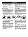
_DANGER:
This cutting machine is capable of amputating
hands
throwing objects. Failure to observe the following safety instructions
in serious injury or death.
and feet and
could result
_WARNING:
In order to prevent accidental starting when setting up, transporting,
adjusting or making repairs, always disconnect spark plug wire and place wire where
it cannot contact spark plug.
•
Never direct discharged material toward
anyone.
Avoid
discharging
material
against a wall or obstruction.
Material
may ricochet back toward the operator.
Stop the blades when crossing gravel
surfaces.
_WARNING:
Do not coast down a hill in
neutral, you may lose control of the tractor.
•
Do not operate machine without the entire grass catcher, discharge chute, or
other safety devices in place and working.
Slow down before turning.
Never leave a running machine unattended.
Always turn off blades, set
parking brake, stop engine, and remove
keys before dismounting.
Disengage
blades when not mowing.
Shut off engine and wait for all parts to
come to a complete stop before cleaning
the machine, removing the grass catcher,
or unclogging the discharge chute.
Operate machine only in daylight or good
artificial light.
Do not operate the machine while under
the influence of alcohol or drugs.
Watch for traffic when operating near or
crossing roadways.
Use extra care when loading or unloading
the machine into a trailer or truck,
_WARNING:
Tow only the attachments
that are recommended
by and comply with
specifications
of the manufacturer
of your
tractor. Use common sense when towing.
Operate only at the lowest possible speed
when on a slope. Too heavy of a load, while
on a slope, is dangerous.
Tires can lose
traction with the ground and cause you to
lose control of your tractor.
•
•
•
_WARNING:
Engine exhaust, some of
its constituents,
and certain vehicle components contain or emit chemicals known to the
State of California to cause cancer and birth
defects or other reproductive
harm.
o
°
•
_WARNING:
Battery posts, terminals and
related accessories
contain lead and lead
°
compounds, chemicals known to the State of
California to cause cancer and birth defects
or other reproductive
harm. Wash hands
after handling.
°
°
I. GENERAL
OPERATION
• Read, understand, and follow allinstructions on the machine and in the manual
before starting.
° Do not put hands or feet near rotating
parts or under the machine. Keep clear
of the discharge opening at all times°
. Only allow responsible adults, who are
familiar with the instructions,to operate
the machine.
• Clear the area of objects such as rocks,
toys, wire, etc., which could be picked
up and thrown by the blades°
o Be sure the area is clear of bystanders
before operating. Stop machine if anyone
enters the area.
° Never carry passengers.
° Do not mow in reverse unless absolutely
necessary. Always look down and behind
before and while backing,
•
°
3
AIwaysweareye
protection when operating machine°
Data indicates that operators, age 60
years and above, are involved in a large
percentage of riding mower-related
injuries. These operators should evaluate
their ability to operate the riding mower
safely enough to protect themselves and
others from serious injury.
Follow the manufacturer's
recommendation for wheel weights
or counterweights.
Keep machine free of grass, leaves or
other debris build-up which can touch hot
exhaust/engine
parts and burn. Do not
allow the mower to plow leaves or other
debris which can cause build-up to occur. Clean any oil or fuel spillage before
operating or storing the machine. Allow
machine to cool before storage.
II. SLOPE
OPERATION
Slopes are a major factor related to loss of
control and tip-over accidents, which can
result in severe injury or death. Operation
on all slopes requires extra caution, tf you
cannot back up the slope or if you feel uneasy
on it, do not mow it.
•
Mow up and down slopes, not across.
, Watch for holes, ruts, bumps, rocks, or
other hidden objects.
Uneven terrain
could overturn the machine.
Tal! grass
can hide obstacles_
• Choose a low ground speed so that you
will not have to stop or shift while on the
slope.
•
Do not mow on wet grass. Tires may lose
traction.
Always keep the machine in gear when
going down slopes. Do not shift to neutral
and coast downhill.
• Avoid starting, stopping, or turning on a
slope. Ifthetireslosetraction,
disengage
the blades and proceed slowly straight
down the slope.
•
Keep all movement on the slopes slow
and gradual.
Do not make sudden
changes
in speed or direction, which
could cause the machine to roll over.
.
Use extra care while operating machine
with grass catchers or other attachments;
they can affect the stability of the machine. Do no use on steep slopes.
.
Do not try to stabilize the machine by
putting your foot on the ground.
.
Do not mow near drop-offs,
ditches,
or embankments.
The machine could
•
Never carry children,
even with the
blades shut off. They may fall off and
be seriously injured or interfere with safe
machine operation. Children who have
been given rides in the past may suddenly
appear in the mowing area for another
ride and be run over or backed over by
the machine.
-
Never allow children
chine.
•
Use extra care when approaching
blind
corners, shrubs, trees, or other objects
that may block your view of a child.
to operate
the ma_
iV. TOWING
•
•
•
•
•
Tow only with a machine that has a hitch
designed for towing. Do not attach towed
equipment except at the hitch point.
Fotlowthemanufacturer's
recommendation for weight limits for towed equipment
and towing on slopes.
Never allow children or others in or on
towed equipment.
On slopes, theweightofthetowedequipment may cause loss of traction and loss
of control.
Travel slowly and allow extra distance
stop.
to
V. SERVICE
SAFE HANDLING
OF GASOLINE
To avoid personal injury or property' damage, use extreme care in handling gasoline.
Gasoline is extremely flammable and the
vapors are explosive.
•
Extinguish all cigarettes,
cigars, pipes,
and other sources of ignition°
,
Use only approved gasoline container.
Never remove gas cap or add fuel with
the engine running. Allow engine to coo!
before refueling.
° Never fuel the machine indoors.
Never storethe machine orfuelcontainer
suddenly roll over if a wheel is over the
edge or if the edge caves in.
Ill. CHILDREN
Tragic accidents can occur if the operator
is not alert to the presence
of children.
Children are often attracted to the machine
and the mowing activity.
Never assume
that children will remain where you last
saw them.
•
Keep children out of the mowing area
and in the watchful care of a responsible
adult other than the operator.
•
Be alert and turn machine off if a child
enters the area.
,
Before and while backing, look behind
and down for small children.
•
•
where there is an open flame, spark, or
pilot light such as on a water heater or
other appliances.
Never fill containers inside a vehicle or
on a truck or trailer bed
Always place containers
away from your vehicle
Remove gas-powered
the truck or trailer and
with plastic liner.
on the ground
when filling.
equipment from
refuel it on the
ground. If this is not possible, then refuel
such equipment with a portable container,
rather than from a gasoline dispenser
nozzle,
4
,
°
°
Keep the nozzle in contact with the rim
of the fuel tank or container opening at
all times until fueling is complete, Do not
use a nozzle lock-open device.
if fuel is spilled on clothing, change clothing immediately.
Never overfill fuel tank. Replace gas cap
and tighten securely.
o
°
GENERALSERVICE
°
•
°
°
o
•
°
°
°
Never operate
machine
in a closed
area.
Keep all nuts and bolts tight to be surethe
equipment is in safe working condition.
Nevertamperwithsafetydevices.Check
their proper operation regularly.
Keep machine free of grass, leaves, or
other debris build-up.
Clean oil or fuel
spillage and remove any fuel-soaked debris. Allow machine to cool before storing.
•
•
•
Do not mow in reverse unless absolutely
necessary, Always look down and behind
before and while backing°
Never carry children,
even with the
blades shut off. They may fall off and
be seriously injured or interfere with safe
machine operation° Children who have
been given rides inthe past may suddenty
appear in the mowing area for another
ride and be run over or backed over by
the machine.
Keep children out of the mowing area
and in the watchful care of a responsible
adult other than the operator.
Be alert and turn machine off if a child
enters the area.
,
Never carry' passengers,
•
Before and while backing, look behind
and down for small children.
Mow up and down slopes (15 ° Max), not
across_
Choose a low ground speed so that you
will not have to stop or shift while on the
slope,
Avoid starting, stopping, or turning on a
slope, lfthetires lose traction, disengage
the blades and proceed slowly straight
down the slope.
If machine
stops while going uphill,
disengage blades, shift into reverse and
back down slowly.
Do not turn on slopes unless necessary,
and then, turn slowly and gradually
downhill, if possible.
°
•
•
•
•
5
If you strike a foreign object, stop and
inspectthe machine. Repair, if necessary,
before restarting.
Never make any adjustments
or repairs
with the engine running.
Check grass catcher components and the
discharge chute frequently and replace
with manufacturer's recommended parts,
when necessary.
Mower blades are sharp. Wrapthe blade
or wear gloves, and use extra caution
when servicing them.
Check brake operation frequently. Adjust
and service as required_
Maintain or replace safety and instruction
labels, as necessary.
Be sure the area is clear of bystanders
beforeoperating.
Stop machine ifanyone
enters the area.
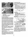
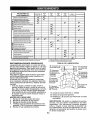
PRODUCT SPECIFiCATiONS
Gasoline Capacity
and Type:
4 Gallons
Unleaded
Oil Type
(API-SG-SL):
SAE 10W30(above 32°F)
SAE 5W30(below 32°F
Oil Capacity:
64 oz
Spark
Champion RC! 2YC
(Gap: .030")
Ground
(MPH):
Plug:
Speed
Forward:
1st
2nd
3rd
4th
5th
6th
Reverse:
In the state of California the above is required
by law (Section 4442 of the California Public
Resources Code). Other states may have
similar laws. Federal taws apply on federal
lands.
A spark arrester for the muffler is
available through your nearest Sears service
center (See REPAIR PARTS manual).
Regular
REPAIR PROTECTaON
AGREEMENTS
Congratulations on making a smart purchase.
Your new Craftsman®
product is designed
and manufactured for years of dependable
operation. But like all products, it may require
repair from time to time. That's when having
a Repair Protection Agreement can save you
money and aggravation.
Purchase a Repair Protection Agreement
now and protect yourself from unexpected
hassle and expense°
Here's what's included in the Agreement:
• Expert service by our 12,000 profesional
repair specialists.
• Unlimited service and no charge for parts
and labor on al! covered repairs.
° Product
replacement
if your covered
product can't be fixed.
- Discount of 10% from regular price of service and service-related
parts not covered
by the agreement;
also, 10% off regular
price of preventive maintenance
check.
, Fast help by phone - phone support from
a Sears representative
on products requiring in-home repair, plus convenient repair
scheduling_
Once you purchase
the Agreement,
a
simple phone call is all that it takes for you
to schedule service. You can call anytime
day or night, or schedule a service appoint_
ment online.
Sears has over 12,000 professional
repair
specialists,
who have access to over 4.5
million quality parts and accessories.
That's
the kind of professionalism
you can count on
to help prolong the life of your new purchase
for years to come. Purchase your Repair
Protection Agreement
todayl
Some limitations and exclusfons apply.
For prices and additional information call
1-800-827-6655.
1.0
1.4
2.1
3.1
4.0
5 ol
1.6
Charging System:
15 Amps @ 3600 RPM
Battery:
Amp/Hr:
28
Min, CCA: 230
Case size: U1R
Blade Bolt Torque:
45-55 FL Lbs.
CONGRATULATIONS
on your purchase of
a new tractor. It has been designed, engineered and manufactured to give you the best
possible dependability
and performance.
Should you experience
any problem you
cannot easily remedy, please contact a
Sears or other qualified service center. We
have competent,
well-trained
technicians
and the proper tools to service or repair
this tractor.
Please read and retain this manual.
The
instructions
will enable you to assemble
and maintain your tractor properly. Always
observe the "SAFETY RULES".
CUSTOMER
RESPONSIBILITIES
• Read and observe the safety rules.
• Follow a regular schedule in maintaining,
caring for and using your tractor.
• Follow the instructions
under "Maintenance" and "Storage"
sections
of this
owner's manual,
_WARNING:
This tractor is equipped with
an internal combustion engine and should not
be used on or near any unimproved forestcovered, brush-covered
or grass-covered
land unless the engine's exhaust system is
equipped with a spark arrester meeting applicable local or state laws (if any). lfa spark
arrester is used, it should be maintained
in
effective working order by the operator.
SEARS INSTALLATION
SERVICE
For Sears professional
installation of home
appliances,
garage door openers,
water
heaters, and other major home items, in the
U.S,A. call 1-800-4-M"I-HOME®
6
i
©
ii
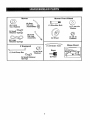
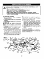
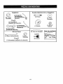
Mower
Mower
Front Wheel
(2) Rear _'_'_
Lift Link
(s)t_3/16
O.D. Washers
_-'3
(1) Shoulder Bolt
©
(1) 1-1/40.D.
Washer
Assemblies _
(1) Small
Retainer Springs
@
(1) Front
Lift Link
Assembly
(1) Wheel
(1) 3/8-16
Locknut
(5) Large
Retainer Springs
(t) Anti-Sway Bar
(1) Oil Drain Tube
Q
If Equipped
Keys
(1) 3/40.D.
Washers
12) Keys
(1) Small Retainer
Springs
7
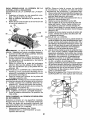
Slope Sheet
Your new tractor has been assembled
at the factory with exception
of those parts lefl
unassembled
for shipping purposes.
To ensure safe and proper operation of your tractor
all parts and hardware you assemble must be tightened securely,
Use the correct tools
as necessary to insure proper tightness.
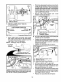
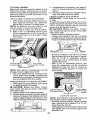
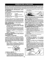
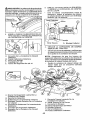
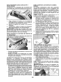
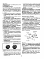
ADJUST SEAT
TOOLS
REQUIRED
1. Sit in seat.
2. Liftup adjustmentlever
(A) andstide seat
until a comfortable
position is reached
which allows you to press clutch/brake
pedal all the way down.
3. Release lever to lock seat in position_
FOR ASSEMBLY
A socket wrench set will make assembly
easier. Standard wrench sizes are listed.
(2) 7/16" wrenches
Utility knife
(1) !/2" wrench
Tire pressure
(1) 3/4" wrench
Pliers
(t) 3/4" socket w/drive
(1) 9/16" wrench
gauge
ratchet
Flashlight
When right or left hand is mentioned in this
manual, it meanswhenyou
arein theoperating
position (seated behind the steering wheel).
TO
REMOVE
TRACTOR
FROM
CARTON
UNPACK
•
-
•
•
,A WARNING:
Before starting, read, understand and follow all instructions
in the
CARTON
Remove all accessible loose parts and
parts cartons from carton o
Cut along dotted lines on all four panels
of carton. Remove end panels and lay
side panels flat.
Remove mower and packing materials.
Check for any additional loose parts or
cartons and remove.
BEFORE REMOVING
FROM SKID
TO CHECK
t.
NOTE: You may now roll your tractor off the
skid. Follow the instructions below to remove
the tractor from the skid.
Operation section of this manual° Be sure
tractor is in a well-ventilated
area. Be sure
the area in front of tractor is clear of other
people and objects,
,
section
OFF
for
SKID
(See
Docation
and
t.
Raise attachment
lift lever to its highest
position.
2. Release parking brake by depressing
clutch/brake
pedal.
3. Place gearshift lever in neutral position.
4. Roll tractor forward off skid.
TRACTOR
position.
NOTE: If this battery is put into service after
month and year indicated on label (label is
located between terminals) charge battery
for minimum of one hour at 6-'I 0 amps. (See
"BATTERY" in Maintenance
section of this
manual for charging
TRACTOR
Operation
function of controls)
BATTERY
Lift hood to raised
TO ROLL
Continue with the instructionsthat follr,lw.
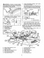
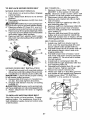
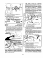
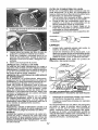
TO INSTALL MOWER
1, SET PARKING
BRAKE
LEVER AND
LOWER ATTACHMENT
LIFT LEVER
instructions).
°
Forbatteryandbatterjcableinstallationsee
"REPLACING
BATTERY" in the "Service
andAd ustments" section in this manual.
Depress clutch/brake
down and hold.
pedal all the way
Pull parking brake lever up and hold,
release pressure from clutch/brake pedal,
then release parking brake lever, Pedal
should remain in brake position. Ensure
parking brake will hold tractor secure.
abel
Brake
8
_CAUTION:
Lift lever is spring loade&
Have a tight grip on lift lever, lower it slowly
and engage in lowest position. Lift lever is
located on left side of fender.
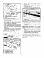
3,
TURN STEERING
WHEEL
POSITION MOWER
°
Turn steering wheel to the left as far as it
will go and position mower on right side of
tractor with deflector shield (Q) to the right,
Front
2. ASSEMBLE
FRONT
(W) TO FRONT
GAUGE
LEFT AND
ine
WHEEL
OF MOWER
Transaxle
Back
Q, Deflector Shield
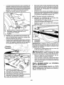
4o SLIDE
o
H.
W,
X
Y,
Zo
Front Mower Bracket
Front Gauge Wheel
Shoulder Bolt
t-1/40,Do Washer
3/8.-16 Locknut
Ao
B,
C.
D.
E.
F.
H.
Mower Side Suspension Arms
Retainer Spring
Rear Lift Link(S)
Right Side Rear Mower Bracket
Front Lift Link Assembly
Front Suspension Bracket
Front Mower Bracket
MOWER
UNDER
TRACTOR
Bring belt forward and check belt for
proper routing in all mower pulley grooves.
NOTE: Be sure mower side suspension
arms (A) are pointing forward before sliding
mower under tractor°
o
Slide mower under tractor
centered under tractor.
Io Left Side Rear Mower Bracket
K, Belt Tension Rod
L,
M.
Q.
S.
W,
Locking Bracket
Engine Clutch Pulley
Deflector Shield
Anti-Sway Bar
Front Gauge Wheel
until
it is
o
•
Pivot the integrated washer end of antisway bar (S) towards mower deck bracket
on right side of mower. Insert integrated
washer end of bar into hole in rear mower
bracket (D)_ Move mower as needed to
insert integrated washer end of bar into
rear mower bracket (D).
Secure with small washer and small
retainer
spring as shown.
A, Mower Side Suspension Arms
Q. Deflector Shield
5.
_.
INSTALL ANTI-SWAY
(IF EQUIPPED)
Towards
ANTI-SWAY
Transaxle
BAR (S)
BAR Towards
(S)
Mower Deck
I
Integrated Washer End
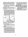
6. ATTACH MOWER SIDE SUSPENSION
ARMS (A) TO CHASSIS
From right side of mower, first insert
90 ° end of anti-.sway bar (S) into hole in
transaxle bracket (T), located near left
rear tire in front of transaxle.
NOTE:
Flashlight
Anti-Sway
Bar (S)
•
Position front hole in side suspension arm
(A) over pin on outside of tractor chassis
and secure with large washer and large
retainer spring (B) o
,
Repeat on opposite
may be helpful.
..........
side of tractor.
.....
Trans_xle Bracket ('1")
Located Between Rear Tires
A, Mower Side Suspension Arms
B, Retainer Spring
D. Right Side Rear Mower Bracket
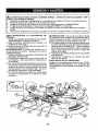
7. ATTACH
°
Insert rod end of rear lift link (C) into hole
(U) in tractor lift shaft suspension
arm
and pivot link down to mower.
•
Lift rear corner of mower and position slot
in link assembly over pin on rear mower
bracket (D) and secure with large washer
and large retainer spring.
•
Repeat on opposite
NOTE: Depending on model, bracket (T) may
be different than shown but hole for anti-sway
bar will be in same position/location.
10
REAR LIFT LINKS (C)
side of tractor.
9
INSTALL
BELT ON ENGINE
PULLEY
(M)
rod
CLUTCH
•
Disengage
belt tension
locking bracket (L)_
(K) from
o
Install belt onto engine clutch pulley (M) o
ar Lift Link(s)
[D: Right Side Rear Mower Bracket
[ 'U. Hole
8
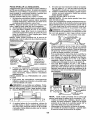
ATTACH
.
Turn steering wheel
straight forward.
°
From front of tractor, insert rod end of
front link (E) through front hole in tractor
front suspension bracket (F).
Move to left side of mower and and insert
large retainer spring (G) through hole in
front link (E) behind front suspension
bracket (F).
.
.
FRONT
LINK (E)
to position
wheels
IMPORTANT:
Check belt for proper routing
in all mower pulley grooves
and under
mandrel covers.
*
Requires
deck lifting.
o
r)
S
Front Link
It
/
I
j
_ .....
....
.
Raise attachment
position.
°
if necessary,
adjust
gauge
wheels
before operating mower as shown in the
Operation section of this manual,
MOWER
,..,
in the "Service
this manual.
Front Lift Link Assembly
Front Suspension Bracket
Large Retainer Spring
Front Mower Bracket
Small Retainer Spring
Engine Clutch Pulley
11
lift lever
to highest
DRIVE BELT INSTALLATION
Follow
procedure
REPLACE MOWER
R
G,
Ho
J,
M°
rod (K) on locking
_CAUTION:
Belt tension rod is spring
loaded. Have a tight grip on rod and engage
slowly.
Insert other end of link (E) into hole in
front mower bracket (H) and secure with
washer and small retainer spring (J).
NOTE:
Engage belt tension
bracket (L).
described
in "TO
BLADE DRIVE BELT'
and Adjustments"
section of
CHECK
TIRE
PRESSURE
_'CHECKLIST
The tires on your tractor were over-inflated
at the factory for shipping purposes. Correct
tire pressure is important for best cutting
performance.
, Reduce tire pressure to PS! shown on tires.
Before you operate your new tractor, we
wish to assure that you receive the best
performance and satisfaction from this
Quality Product.
CHECK
Please review the following
DECK
LEVELNESS
For best cutting results, mower housing
should be properly leveled_ See "TO LEVEL
MOWER" in the Service and Adjustments
section of this manual.
J" All assembly
completed.
J" No remaining
CHECK FOR PROPER POSITION OF
ALL BELTS
See the figures that are shown for replacing
motion and mower blade drive belts in the
Service and Adjustments section ofthis manual. Verify that the belts are routed correctly_
CHECK BRAKE SYSTEM
After you learn how to operate your tractor,
check to see that the brake is operating properly. See "TO CHECK BRAKE" in the Service
and Adjustments section of this manual.
checklist:
instructions
have
been
loose parts in carton°
t/f Battery
is properly
prepared
and
charged.
t/" Seat is adjusted comfortably
and tightened securely.
t/' All tires are properly inflated. (For shipping purposes, the tires were overinflated
at the factory).
_' Be sure mower deck is properly leveled
side-to-side/front-to-rear
for best cutting
results. (Tires must be properly inflated
for leveling),
J" Check mower and drive belts. Be sure
_
they are routed properly around pulleys
and inside all belt keepers.
Check wiring. See that all connections
are still secure and wires are properly
clamped.
While learning howto use your tractor, pay extra attention to the following important items:
_" Engine oil is at proper level.
J"
Fueltank is filledwith fresh, clean, regular
unleaded gasoline.
v/" Become familiar with all controls, their
location and function.
Operate them
before you start the engine.
t/" Be sure brake system is in safe operating
condition.
t/' Be sure Operator Presence System and
Reverse Operation
System (ROS) are
working properly (See the Operation and
Maintenance
sections in this manual)_
12
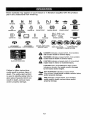
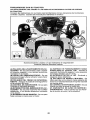
These symbols may appear on your tractor
Learn and understand their meaning.
R
N
H
L
REVERSE
NEUTRAL
HIGH
LOW
ENGINE OFF
REVERSE
OPERATIDN
ENGINE ON
or in literature
CHOKE
ENGINE START
supplied
FAST
PARKING BRAKE
with the product.
St.OW
MOWER HEIGHT
IGNITION SWITCH
MOWER LIFT
SYSTEM(ROS)
;U'
LIGHTS ON
FUEL
ATfACHMENT
CLUTCH DISENGAGED
BATTERY
ATTACHMENT
CLUTCH ENGAGED
FREE WHEEL
(Automatic Models only)
!
FORWARD
REVERSE
DANGER, KEEP HANDS
AND FEET AWAY
A
A
A
CRUISE CONTROL
CLUTCH/BRAKE
PEDAL
KEEP AREA CLEAR
SLOPE HAZARDS
(SEE SAFETY RULES SECTION)
DANGER indicates a hazard which, if not avoided,
will result in death or serious injury.
WARNING indicates a hazard which, if not avoided,
could result in death or serious injury.
CAUTION indicates a hazard which, if not avoided,
might result in minor or moderate injury.
CAUTION when used without the alert symbol,
_ndfcates a situation that could result in damage
to the tractor and!or engine.
Failure to follow instructions
could result in serious injury or
death, The safety alert symbol
is used to identify safety information about hazards which can
result in death, serious injury
and/or property damage.
HOT SURFACES indicates a hazard which,
if not avoided, could result in death, serious Injury
and/or property damage.
FIRE indicates a hazard which,if not avoided,
could result In death, serious Injury and/or
property damage,
13
KNOW YOUR TRACTOR
READ THIS OWNER'S
TRACTOR
MANUAL
AND SAFETY
RULES
BEFORE
OPERATING
Compare the illustrations
with your tractor to familiarize yourself with the locations
various controls and adjustments,
Save this manual for future reference,
YOUR
of
03065
Our tractors
conform to the applicable safety standards
dards Institute.
of the American
National
Stan-
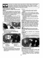
(G) REVERSE
OPERATION
SYSTEM
(ROS) "ON" POSITIONAllows operation
of mower or other powered attachment while
in reverse.
(H) LIGHT SWITCH - Turns the headlights
on and off.
(J) GEARSHIFT
LEVER - Selects the speed
and direction of the tractor,
(N) CHOKE CONTROLUsed when starting
a cold engine
(P) SERVICE REMINDER / HOUR METER
- Indicates when service is required for the
engine and mower,
(A) ATTACHMENT
LIFT LEVER - Used to
raise and lower the mower or other attachments mounted to your tractor,
(B) CLUTCH/BRAKE
PEDAL - Used for
declutching
and braking the tractor and
starting the engine°
(C) PARKING BRAKE - Locks clutch/brake
pedal into the brake position,
(D) THROTTLE CONTROLUsed to control
engine speed.
(E) ATTACHMENT
CLUTCH SWITCH Used to engage the mower blades, or other
attachments
mounted to your tractor,
(F) IGNITION
SWITCH - Used for starting
and stopping the engine.
14
The operation of any tractor can result in foreign objects thrown into the
eyes, which can result in severe eye damage.
Always wear safety glasses
or eye shields while operating your tractor or performing
any adjustments
or repairs. We recommend standard safety glasses or a wide vision safety
mask worn over spectacles.
HOW TO USE YOUR TRACTOR
TO SET PARKING BRAKE
Your tractor is equipped with an operator
presence sensing switch, When engine is
running,any attempt by the operator to leave
the seat withoutfirst setting the parking brake
will shut off the engine.
1, Depress clutch/brake pedal (B) all the
way down and hold,
2, Pull parking brake lever (C) up and hold,
release pressure from brake pedal (B),
then release parking brake lever° Pedal
should remain in brake position. Make
sure parkingbrake willholdtractorsecure°
NOTE: Failuretomovethrottlecontrolbetween
half and ful! speed (fast) position, before
stopping, may cause engine to "backfire".
• Turn ignition key (F) to "STOP" position
and remove key, Always remove keywhen
leaving tractor to prevent unauthorized use,
° Never use choke (N) to stop engine.
IMPORTANT:
Leaving the ignition switch in
any position other than "STOP" will cause
the battery to discharge and go dead.
NOTE: Under certain conditions when tractor
is standing idle with the engine running, hot
engine exhaust gases may cause "browning" of grass. To eliminate this possibility,
always stop engine when stopping tractor
on grass areas,
_CAUTION:
Always stop tractor completely, as described above, and set parking
brake before leaving the operator's position,
TO USE THROTTLE
STOPPING
MOWER
BLADES
-
• To stop mower blades, move attachment
clutch clutch lever to "DISENGAGED"
position (_).
Attachment
Clutch Switch
"Engaged"
GROUND
DRIVE
"Disengaged"
-
,,
• Move throttle control (D) between
full speed (fast) position,
CONTROL
(N)
Use choke control whenever you are starting
a cold engine. Do not use to start a warm
engine.
• To engage choke control, pull knob out,
Slowly push knob in to disengage,
(t"_l)Attachment
Clutch Switch
• To stop ground drive, depress clutch/brake
pedal all the way down.
, Move gear shift
lever (J) to neutral
position,
ENGINE
(D)
Always operate engine at full speed (fast).
, Operating engine at less than full speed
(fast) reduces
engine's
operating
efficiency,
• Full speed (fast) offers the best mower
performance.
TO USE CHOKE
(r_)
CONTROL
half and
15
TO MOVE FORWARD
AND BACKWARD
The direction and speed of movement
controlled by the gearshift
lever (J)o
TO ADJUST
is
GAUGE
WHEELS
Gauge wheels are properly adjusted when
they are slightly off the ground when mower
is at the desired cutting height in operating
position, Gauge wheels then keep the deck
in proper position to help prevent scalping
in most terrain conditions.
NOTE: Adjust gauge wheels with tractor on
a flat level surface.
t.
2,
3.
1. Adjust mower to desired cutting height
(See "TO ADJUST MOWER CUTTING
HEIGHT" in this section of manual),
2. With mower in desired height of cut position, gauge wheels should be assembled
so they are slightly off the ground, Install
gauge wheel in appropriate hoteo Tighten
securely.
3. Repeat for all, installing gauge wheel in
same adjustment
hole.
Start tractor with clutch/brake
pedal
depressed and gearshift lever in neutral
position.
Move gearshift lever to desired position.
Slowly release clutch/brake pedalto start
movement.
IMPORTANT: Bring tractorto acomplete stop
before shifting or changing gears. Failure to do
so will shorten the useful life of your transaxle.
TO ADJUST MOWER CUTTING HEIGHT
"_
9/t6
The position of the attachment lift lever (A)
determines the cutting heighL
TO OPERATE
MOWER
Your tractor is equipped with an operator
presence sensing switch, Any attempt by
the operator to leave the seat with the
engine running and the attachment
clutch
engaged will shut off the engine. You must
remain fully and centrally positioned in the
seat to prevent the engine from hesitating or
cutting off when operating your equipment
on rough, rolling terrain or hills.
1, Select desired height of cut with attachment lift tever_
• Put attachment lift lever in desired cutting
height slot.
• Slide pointer tab (T) to desired cutting
height as a reminder for next time you
2o Start mower blades by engaging
ment clutch control.
TO STOP MOWER BLADES
mow.
The cutting height range is approximately
1 to 4". The heights are measured from the
ground to the blade tip with the engine not
running. These heights are approximate
and may vary depending
upon soil conditions, height of grass and types of grass
being mowed,
, The average lawn should be cut to approximately
2-1/2" during the cool season and to over 3" during hot months,
For healthier and better looking lawns,
mow often and after moderate
growth,
° For best cutting performance,
grass over
6" in height should be mowed twice. Make
the first cut relatively high; the second to
desired height.
Disengage
attachment
attach-
clutch control.
_CAUTION:
Do not operate the mower
without either the entire grass catcher, on
mowers so equipped, or the deflector shield
(S) in place,
16
REVERSE OPERATION SYSTEM (ROS)
Your tractor is equipped
with a Reverse
Operation
System (ROS). Any attempt by
the operator to travel in the reverse direction
with the attachment clutch engaged will shut
off the engine unless ignition key is placed
in the ROS "ON" position.
_WARNING:
Backing
up with the attachment
clutch engaged while mowing is
strongly discouraged. Turning the ROS "ON",
to allow reverse operation with the attachment clutch engaged, should only be done
when the operator decides it is necessary to
reposition the machine with the attachment
engaged, Do not mow in reverse unless
absolutely
necessary_
USING THE REVERSE
SYSTEM -
OPERATION
Only use ifyou are certain no children or other
bystanders will enter the mowing area.
1. Depress clutch/brake
pedal all the way
down and hold.
2. With engine running, turn ignition key
counterclockwise
to ROS "ON" position.
3. Look down and behind before backing.
4. Move gear shift lever to reverse position
and slowly release clutch/brake pedal to
start movement.
5, When use ofthe ROS is no longer needed,
turn the ignition key clockwise to engine
"ON" position.
ROS "ON" Posffion
TO TRANSPORT
• Raise attachment
lift lever to its highest
position,
° When pushing or towing your tractor, be
sure gearshift lever is in neutral position.
o Do not push or tow tractor at more than
five (5) MPH.
NOTE: To protect hood from damage when
transporting your tractor on a truck or a trailer,
be sure hood is closed and secured to tractor.
Use an appropriate means of tying hood to
tractor (rope, cord, etc.).
TOWING
MENTS
CARTS
AND OTHER
'Tow only the attachments
that are recommended by and comply with specifications
of the manufacturer
of your tractor, Use
common sense when towing_ Too heavy of
a load, while on a slope, is dangerous. Tl-'res
can lose traction with the ground and cause
you to lose control of your tractor.
SERVICE REMINDER/HOUR
METER
Service reminder shows the total number
of hours the engine has run and flashes to
indicate that the engine or mower needs servicing. When service is required, the service
reminder will flash for two hours, To service
engine and mower, see the Maintenance
section of this manual.
NOTE: Service reminder runs when the ignition key is in any position but "STOP"° For
acurate reading, be sure key remains in the
"STOP" position when engine is not running,
Engine "ON" Position
(Nor
Operating)
BEFORE STARTING THE
CHECK
TO OPERATE
ATTACH-
ENGINE
ENGINE
OIL LEVEL
The engine in your tractor has been shipped,
from the factory, already filled with summer
weight oil.
I. Check engine oil with tractor on level
ground.
2. Unthread and remove oil fill cap/dipstick;
wipe oil off. Reinsert the dipstick into the
tube and rest oil fill cap on the tube. Do
not thread the oap onto the tube. Remove
and read oil level. If necessary, add oil
until "FULE' mark on dipstick is reached°
Do not overfill.
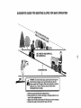
ON HELLS
,_WARNING:
Do not drive up or down hills
with slopes greater than 15 ° and do not drive
across any slope. Use the slope guide atthe
back of this manual.
• Choose the slowest speed before starting
up or down hills.
• Avoidstoppingorchanging
speed on hills.
• if stopping is absolutely necessary, push
clutch/brake pedal quickly to brake position
and engage parking brake.
• Move gearshift lever to 1st gear. Be sure
you have allowed room for tractor to roll
slightly as you restart movement.
- To restart movement, slowly release parking brake and clutch/brake
pedal.
, Make all turns slowly.
• For cold weather operation you should
change oil for easier starting (See the oil
viscosity chart in the Maintenance section
of this manual).
° To change engine oil, seethe Maintenance
section in this manual.
17
ADD GASOLINE
° Fill fuel tank to bottom of filler neck° Do
not overfill.
Use fresh, clean, regular
unleaded
gasoline with a minimum
of
87 octane.
(Use of leaded gasoline will
increase carbon and lead oxide deposits
and reduce valve life). Do not mix oil with
gasoline° Purchase fuel in quantities that
can be used within 30 days to assure fuel
freshness.
,_CAUTION:
Wipe off any spilled oil or fuel.
Do not store, spill or use gasoline near an
open flame,
IMPORTANT:
When operating in temperatures be!ow32 ° F(0°C), use fresh, clean winter
grade gasoline to help ensure good cold
weather starting.
CAUTION:
Alcohol blended fuels (called
gasoho! or using ethanol or methanol) can
attract moisture which leads to separation
and formation of acids during storage° Acidic
gas can damage the fuel system of an engine
while in storage. To avoid engine problems,
the fuel system should be emptied before
storage of 30 days or longer. Drain the gas
tank, start the engine and let it run until the
fiJel lines and carburetor are empty. Use fresh
fuel next season. See Storage Instructions
for additional information.
Never use engine
or carburetor cleaner products in the fueltank
or permanent damage may occur.
RESERVE
TO START ENGINE
When starting the engine for the first time or
if the engine has run out of fuel, it will take
extra cranking time to move fuel from the
tank to the engine.
1. Sit on seat in operating position, depress
clutch/brake pedal and set parking brake.
2. Place gear shift lever in neutral position.
3. Move attachment clutch to disengaged
position.
4. Move throttle control to fast position
5. Putlchoke controloutfor a cold engine start
attempt. For awarm engine start attempt
the choke control may not be needed.
NOTE. Before starting, read the warm and
cold starting procedures below.
6. Insert key into ignition and turn key
clockwise to start position and release
key as soon as engine starts. Do not run
starter continuously for more than fifteen
seconds per minute, if the engine does
not start after several attempts,
push
choke control in, wait a few minutes and
try again. If engine still does not start, pull
the choke control out and retry.
WARM WEATHER STARTING (50°1=/10°C
and above)
7. When engine starts, slowly push choke
control in until the engine begins to run
smoothly.
If the engine starts to run
roughly, pull the choke control out slightly
for a few seconds and then continue to
push the control in slowly.
, The attachments
and ground drive can
now be used. If the engine does not accept
the load, restart the engine and allow it to
warm up for one minute using the choke
as described above.
COLD WEATHER STARTING (50°F/10°C
and below)
7. When engine starts, slowly push choke
control in until the engine begins to run
smoothly, Continue to push the choke
control in small steps allowing the engine
to accept small changes in speed and
load, until the choke control is fully in.
if the engine starts to run roughly, pull
the choke control out slightly for a few
seconds and then continue to push the
control in slowly. This may require an
engine warm-up
period from several
seconds to several minutes, depending
on the temperature.
• The attachments
can be used during the
engine warm-up period and may require
the choke control be pulled out slightly.
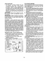
FUEL VALVE OPERATION
1. Raise seat to access reserve fuel valve.
2. in normal operation, valve should be set
to primary (as shown in view)
3. if tractor runs out of fuel, rotate valve
handle to reserve.
4. Drive tractor to be refueled.
5. After refueling,
position.
return valve to primary
Resel've
Fue! Valve
@
Primary
18
NOTE: If at a high altitude (above 3000
feet) or in cold temperatures
(below 32°F)
the carburetor fuel mixture may need to be
adjusted for best engine performance°
See
"TO ADJUST CARBUR ETO R" in the Service
and Adjustments
section
of this manual,
MOWING TIPS
- Tire chains
.
cannot
be used
when
the
mower housing is attached to tractor.
Mowershould
be properly leveledfor best
mowing performance.
See "TO LEVEL
MOWER HOUSING"
in the Service and
Adjustments
section of this manual.
• The left hand side of mower should be
used for trimming.
° Drive so that clippings are discharged
onto the area that has already been cut.
Have the cut area to the right of the tractor.
This will result in a more even distribution
of clippings and more uniform cutting.
o When mowing large areas, start by turning
to the right so that clippings will discharge
away from shrubs, fences, driveways,
etc. After one or two rounds, mow in the
opposite direction making left hand turns
until finished°
, If grass is extremely
tall, it should be
mowed twice to reduce load and possible
fire hazard from dried clippings.
Make
first cut relatively high; the second to the
desired height.
° Do not mow grass when it is wet. Wet
grass will plug mower and leave undesirable clumps.
Allow grass to dry before
mowing.
, Always operate engine at full throttle
when mowing
to assure better mowing performance
and proper discharge
of material.
Regulate ground speed by
selecting a low enough speed to give the
mower cutting performance as well as the
quality of cut desired°
• When operating
attachments,
select a
ground speed that will suit the terrain and
give best performance
of the attachment
being used.
19
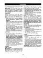
MAINTENANCE
SCHEDULE
Check Brake Operation
DEFO.E EVERY EVE.V
_c.
s
_
use
.ouRs
.ou.s
...........................
_
.....
_
EVE_
_o
.ou.s
EVERY EVE.V BEFO.E
_o0 e_eo. _Io.A_E
.ou.e
.........................................................................
Check Tire Pressure
Check Ope[ator Presence & ROS Systems
A
Check _for
Loose Fasteners
_
C Chec_Beplace Mower Blades
T Lubrication Chart
0
Check
R
Clean
Baltery
€_an
Debris
_/'_
_
Battery Level
and Terminals
..........................."
off Steering Plate
Check Transax!_ Cooling
Check Mower Levelness
Check
Engine
Oil Level
_
=l
....
_
if
.
E
C!ean Air Fttter
_
G
clean
:
0,/
if
,
.....
,
_ti_
.
inspect
Mulf{erlSpark
Replace
E!
Clean
, ,_'
.....
Arrester
6/
_12
Cooling Fins
Spark Plug
_'
Replace Air Fi{ter Paper Cartridge
_;z
_"
...............
_'
ReplaceFuelFilter
4 -*N01 f_nu bed I_ eq__='_edw_thf*'_le_P,t_J
_l_e b_tt¢ _'_'
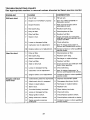
LUBRICATION CHART
GENERAL
RECOMMENDATIONS
The warranty on this tractor does not cover
items that have been subjected to operator
abuse or negligence, To receive full value
from the warranty, operator must maintain
tractor as instructed in this manual.
Some adjustments will need to be made periodically to properly maintain your tractor.
At least once a season, check to see if
you should make any of the adjustments
described in the Service and Adjustments
section of this manual.
• At least once a year you should replace
the spark plug, clean or replace air filter,
and check blades and belts for wear. A
new spark plug and clean air filter assure
proper air-fuel mixture and help your engine run better and last longer.
BEFORE
',
6/_
Oil Filter (If equipped)
Engine
Replace
.........
.
Air Screen
N
_
.
Chan_e Enqtne Otl (with el! filter)
Char_go Engine Oil (wtlhout oil ltiler)
t
......
_
...........................
_ ....
............
_) Spindle
Zerk
(_Front
Bearing zerk
Steering
Sector Gear
Teeth
_SAE
Spindle
Zerk
Wheel
Bearing zerk
(_ Engine
(_ Mandrel
Zerks
_ Check/
Transaxle
Fluid
30 or 10w30 Motor Oil
_Genera!
Purpose Grease
®Refer to Maintenance "ENGINE"
Section
EACH USE
1.
2.
3.
4.
Check engine oil level
Check brake operation.
Check tire pressure.
Check operator presence and
ROS systems for proper operation.
5. Check for loose fasteners_
IMPORTANT:
Do not oil or grease the pivot
points which have special nylon bearings.
Viscous lubricants will attract dust and dirt
that will shorten the life of the self-lubricating
bearings, tfyou feel they must be lubricated,
use only a dry, powdered graphite type lubricant sparingly.
20
TRACTOR
Always observe safety rules when performing
any maintenance.
BRAKE OPERATION
If tractor requires more than five (5) feet to
stop at highest speed in highest gear on a
level, dry concrete or paved surface, then
brake must be serviced. (See "TO CHECK
BRAKE" in the Service and Adjustments
section of this manual).
TIRES
• Maintain proper air pressure in all tires
(See PSI on tires).
• Keep tires free of gasoline, oil, or insect
control chemicals
which can harm rubber.
° Avoid stumps, stones, deep ruts, sharp
objects and other hazards that may cause
tire damage.
NOTE: To seal tire punctures and prevent
flat tires due to slow leaks, tire sealant may
be purchased from your local parts dealer.
Tire sealant also prevents tire dry rot and
corrosion.
OPERATOR
PRESENCE
SYSTEM
AND
RE_#ERSE OPERATION
SYSTEM (ROS)
CHECK
REVERSE
SYSTEM
OPERATOR
BLADE CARE
Forbest results mower blades must be sharp°
Replace worn, bent or damaged blades.
CAUTION:
Use only a replacement
blade approved by the manufacturer of your
tractor. Using a blade not approved by the
manufacturer of your tractor is hazardous,
could damage your tractor and void your
warranty.
BLADE REMOVAL
t, Raise mower to highest position to allow
access to blades.
NOTE: Protect your hands with gloves and/
or wrap blade with heavy cloth.
2. Remove blade bolt by turning counterclockwise.
3. Install newbladewith stamped"THiS
SIDE
UP" facing deck and mandrel assembly.
IMPORTANT:
To ensure proper assembly,
center hole in blade must align with star on
mandrel assembly.
4. Install and tighten blade bolt securely
(45-55 Ft. Lbs. torque).
IMPORTANT:
Special blade bolt is heat
treated.
PRESENCE
• When the engine is running,
by the operator to leave the
first setting the parking brake
off the engine.
° When the engine is running
tachment clutch is engaged,
by the operator to leave the
shut off the engine.
° The attachment clutch should
ate unless the operator is in
ROS "ON" Position
(ROS)
° When the engine is running with the ignition
switch in the engine "ON" position and the
attachment clutch engaged, any attempt
by the operator to shift into reverse should
shut off the engine.
° When the engine is runningwith the ignition
switch in the ROS "ON" position and the
attachment
clutch engaged, any attempt
bythe operator to shift into reverse should
NOT shut off the engine.
Be sure operator presence and reverse
operation systems are working properly° If
your tractor does not function as described,
repair the problem immediately.
, The engine should not start unless the
brake pedal is fully depressed,
and the
attachment clutch control is in the disengaged position.
CHECK
SYSTEM
OPERATION
any attempt
seat without
should shut
Blade
"('-_-._
-,,.,
__'--4Mandrel
Blade Bol[_'_.-"..'z_ - "_>,'_._
_=
and the atany attempt
seat should
Ispoo
l
Assembly
Star
Ce nte( Ho le"'-<.__, _
BATTERY
Your tractor has a battery charging system
which is sufficient for normal use. However,
periodic charging of the battery with an automotive charger will extend its life.
• Keep battery and terminals clean.
• Keep ba[tery bolts tighL
• Keep small vent holes open,
• Recharge at 6-10 amperes for I hour.
NOTE: The original equipment battery on
your tractor is maintenance free. Do not
attempt to open or remove caps or covers,
Adding or checking level of electrolyte is
not necessary,
never operthe seat.
Engine "ON" Position
(Normal Operating)
21
TO CLEAN
BATTERY
AND TERMINALS
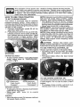
3.
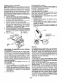
Unlock drain valve by pushing inward
slightly and turning counterclockwise.
4. To open, pull out on the drain valve.
5. After oil has drained completely, close and
lock the drain valve by pushing inward
and turning clockwise until the pin is in
the locked position as shown°
6_ Remove the drain tube and replace the
cap onto the end of the drain valve.
Oil Drain "Valve
Corrosion and dirt on the battery and terminals can cause the battery to "leak" power,
1, Remove terminal guard.
2. Disconnect
BLACK battery cable first
then RED battery cable and remove
battery from tractor.
3. Rinsethe battery with plain water and dry.
4. Clean terminals and battery cable ends
with wire brush until bright,
5. Coat terminals with grease or petroleum
jelly.
6. Reinstall
battery
(See "REPLACING
BATTERY" in the SERVICE AND ADJUSTMENTS
section of this manual),
TRANSAXLE
COOLING
Check V_betts for deterioration and wear after
100 hours of operation and replace if necessary. The belts are not adjustable. Replace
belts if they begin to slip from wear.
, o
TEMPERATURE
, _D = .o
.!o
o
RANGE AkITtCPATED
[----'(. -7_,, _J)._'_
_ _
_
ENGINE
GRADES
, _o
'_o
_o,
°
_
Drain
_Tube
_ ""
Refillengine with oilthrough oilfill dipstick
tube. Pour slowly. Do not overfill.
For
approximate
capacity see "PRODUCT
SPECIFICATIONS"
section ofthis manual.
8_ Use gauge on oil fill cap/dipstick
for
checking level. Insert dipstick into the
tube and rest the oil fill cap on the tube.
Do not thread the cap onto the tube when
taking reading_ Keep oil at "FULl/' line
on dipstick. Tighten cap onto the tube
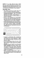
securely when finished.
Only use highquality detergent oil rated with
API service classification SG-SL Selectthe
oil's SAE viscosity grade according to your
expected operating temperature.
.so
_\
7.
ENGINE
LUBRICATION
._o
and
Locked
Yellow Cap;ap
V-BELTS
c _o
_
Position.'_. _....Y
Keep transaxle free from build-up of dirt and
chaff which can restrict cooling.
SAE VlSCOS_
Closed
OIL FILTER
Replace the engine oil filter every season or
every other oil change if the tractor is used
more than 100 hours in one year.
!_o
AIR FILTER
Your engine will not run properly using a
dirty air filter. Service paper cartridge every
two months or every 25 hours of operation,
whichever occurs first,
Service paper cartridge more often under
dusty conditions.
Replace the paper cartridge annually, orafter
every 100 hours of operation.
_ ............
=o...............
_ .....
BEFORE NF-__.'v_
OiL CHANGE
Change the oil after every 50 hours of operation or at least once a year if the tractor is
not used for 50 hours in one year.
Check the crankcase oil level before starting
the engine and after each eight (8) hours of
operation.
TO CHANGE ENGINE OIL
Determine
temperature
range expected
before oil changer
All oil must meet API
service classification SG-SL.
• Be sure tractor is on level surface.
• Oil will drain more freely when warm.
• Catch oil in a suitable container.
TO SERVICE
CARTRIDGE
° Replace a dirty, bent, or damaged cartridge. Handle new cartridge carefully; do
not use if the rubber seal is damaged.
NOTE;
Do not wash the paper cartridge
or use pressurized air, as this will damage
the cartridge.
1. Open door (A) on the blower housing to
access the air cleaner element (B).
2, Unhook the latch (C) and remove the
element.
1. Remove oil fill cap/dipsticL
Be careful
not to allow dirt to enter the engine when
changing oil.
2. Remove yellow cap from end of drain
valve and install the drain tube onto the
fitting.
3.
22
Gently tap the paper element to dislodge
dirt,
IN-LINE
FUEL FILTER
The fuel filter should be replaced once each
season, If fuel filter becomes clogged, obstructing fuel flow to carburetor, replacement
is required.
1. With engine cool, remove filter and plug
fuel line sections.
2. Place newfuel filter in position in fuel line
with arrow pointing towards carburetor.
3. Be sure there are no fuel line leaks and
4_
Clean all air cleaner components
of any
accumulated
dirt or foreign material.
4.
clamps are properly positioned.
Immediatelywipe
up anyspilled gasoline.
Clam_mp
Fuel Filter .__j
z._..j
CLEANING
•
5.
6.
Prevent any dirt from entering the throat
of carburetor°
Install cleaned or new element on the
base and secure with latch.
Close and latch the door,
CLEAN
•
_k CAUTION: Avoid all pinch points and
movable parts
AIR SCREEN
Air screen must be kept free of dirt and chaff
to prevent engine damage from overheating.
Clean with a wire brush or compressed
air to
remove dirt and stubborn dried gum fibers,
_C
CLEAN AIR INTAKE/COOLING AREAS
TOensure propercooling,make sure thegrass
screen, cooling fins, and other external surfaces of the engine are kept clean at alltimes,
Every 100 hours of operation (more often
under extremely dusty, dirty conditions),
remove the blower housing and othercooling
shrouds° Clean the cooling fins and external
surfaces as necessary. Make sure the cooling
shrouds are reinstalled.
NOTE: Operating the engine with a blocked
grass screen, dirty or plugged cooling fins,
and/or cooling shrouds removed will cause
engine damage due to overheating°
MUFFLER
Inspect and replace corroded muffler and
spark arrester (ifequipped) as it could create
a fire hazard and!or damage.
SPARK
Clean engine, battery, seat, finish, etc.
of all foreign matter,
Clean debris from steering plate.
Debris can restrict clutch/brake
pedal
shaft movement, causing belt slip and
loss of drive.
lutch/b rake ped_oy
Steering
o
•
Keep finished surfaces and wheels
free of all gasoline, oil, etc.
Protect painted surfaces with automotive type wax.
We do not recommend using a garden hose
or pressure washer to clean your tractor
unless the engine and transmission
are
covered to keep water out. Water in engine
or transmission will shorten the useful life of
your tractor, Use compressed
air or a leaf
blower to remove grass, leaves and trash
from tractor and mower.
PLUG(S)
Replace spark plug(s) at the beginning of
each mowing season or after every 100
hours of operation, whichever occurs first,
Spark plug type and gap setting are shown
in "PRODUCT
SPECIFICATIONS"
section
of this manual.
23
DECK WASHOUT PORT
9.
",four tractor's
deck is equipped
with a
washout port on its surface as part of its
deck wash system, it should be utilized after each use,
Pull back the lock collar of the nozzle
adapter to disconnect the adapter from
the nozzle washout port.
10.
Move the tractor to a dry area, preferably a concrete or paved area. Place
the attachment
clutch control in the
"ENGAGED" position to remove excess
water and to help dry before putting the
tractor away.
1,
Drive the tractor to a level, clear spot
on your lawn, near enough to a water
spigot for your garden hose to reach.
IMPORTANT:
Make certain the tractor's
discharge chute is directed AWAY from your
house, garage, parked cars, etCo Remove
bagger chute or mulch cover if attached.
2.
Make surethe attachment clutch control
is in the "DISENGAGED"
position, set
the parking brake, and stop the engine.
3.
Thread the nozzle adapter (packaged
with your tractor's Operator's Manual)
onto the end of your garden hose.
4.
Pull back the lock collar of the nozzle
adapter and push the adapter onto the
deck washout port at the left end of the
mower deck. Release the lock collar to
lock the adapter on the nozzte_
Nozzle
Ada
IMPORTANT:
tion is secure.
5.
_WARNING:
A broken or missing washout
fitting could expose you or others to thrown
objects from contact with the blade.
• Replace broken or missing washout fitting
immediately, prior to using mower again.
. Plug any holes in mower with bolts and
Iocknuts.
Washout Port
Tug hose
ensuring
connec-
Turn the water on.
6,
While sitting in the operator's position
on the tractor, re-start the engine and
place the throttle lever in the Fast ,,=€_',
position.
IMPORTANT:
Recheck
the area making
certain the area is clear.
7.
Move the tractor's attachment
clutch
control to the "ENGAGED"
position.
Remain
in the operator's
position
with the cutting deck engaged until the
deck is cleaned.
8,
Move the tractor's
attachment
clutch
control to the "DISENGAGED"
position. Turn the ignition key to the STOP
position to turn the tractor's engine off.
Turn the water off.
24
WARNING:
TO AVOID SERIOUS
SERVICE OR ADJUSTMENTS:
I.
2.
3_
4_
5.
6.
INJURY,
BEFORE
PERFORMING
ANY
Depress clutch/brake pedal fully and set parking brake_
Place gearshift lever in neutral position.
Place attachment clutch in "DISENGAGED"
position_
Turn ignition key to "STOP" and remove key°
Make sure the blades and all moving parts have completely stopped.
Disconnect spark plug wire from spark plug and place wire where it cannot
come in contact with plug.
TO REMOVE
MOWER
io Place attachment
clutch in "DISENGAGED" positiom
2o Lower attachment lift lever to its lowest
_, CAUTION:
position.
Disengage belt tension rod (K) from lock
bracket (L).
CAUTION:
Belt tension rod is spring
loaded. Have a tight grip on rod and release
slowly.
4. Remove mower belt from electric clutch
8. From right side of mower, disconnect
anti-sway bar (S) from right rear mower
bracket (D) - remove retainer spring and
washer and pull mower toward you until
the bar falls from the hole in bracket.
After rear lift links are discom
nected, the attachment lift lever will be spring
loaded. Have a tight grip on lift lever when
changing position of the lever.
3.
9.
"#drntractor steering wheel to the left as
far as it will go.
10. Slide mower out from under right side of
tractor°
pulley (M).
5_ Disconnect front link (E) from mower remove retainer spring and washer.
6. Go to eitherside ofmowerand
disconnect
mower suspension arm (A) from chassis and rear lift link (C) from rear mower
bracket (D) - remove retainer springs and
washers.
7. Go to other side of mower and disconnect
the suspension arm and rear lift link.
TO INSTALL
MOWER
Follow procedure
described
in "INSTALL
MOWER AND DRIVE BELT" in the Assembly
section of this manual.
25
TO LEVEL MOWER
Make sure tires are properly inflated to the
PSI shown on tires, if tires are over or under
inflated, it may affect the appearance of your
lawn and lead you to think the mower is not
adjusted properly.
VISUAL
SIDE-TO-SIDE
ADJUSTMENT
!.
With all tires properly inflated and if your
lawn appears unevenly cut, determine
which side of mower is cutting lower.
NOTE: As desired, you can raise the tow
side of mower or lower the high side.
2. Go to side of mower you wish to adjust.
3. With a 3/4" or adjustable wrench, turn
lift link adjustment
nut (A) to the left to
lower the mower, or, to the right to raise
the mower.
4.
If adjustment is necessary, see steps 2
and 3 in Visual Adjustment
instructions
above.
5. Recheck measurements,
adjust if necessary until both sides are equal.
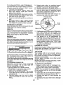
FRONT-TO-BACK
ADJUSTMENT
IMPORTANT:
Deck must be level sideto-side.
To obtain the best cutting results, the mower
blades should be adjusted so the front tip is
1/8" to !/2" lower than the rear tip when the
,_ower is in its highest position.
CAUTION:
Blades are sharp_ Protect
your hands with gloves and/or wrap blade
with heavy cloth.
• Raise mower to highest position.
. Position any blade so the tip is pointing
straight forward. Measure distance (B) to
the ground at front and rear tip of the blade.
,
Iffronttip
of blade is not t/6" to 1/2" lower
than the rear tip, go to the front of tractor°
, With an 11/16" or adjustable
wrench,
loosen jam nut A several turns to clear
adjustment nut B,
• With a 3/4" or adjustable
wrench, turn
front link adjustment
nut (B) clockwise
(Itighten) to raise the front of mower, or,
counterclockwise
(loosen) to lower the
front mower°
Turn nut left
to lower mower
3brn nut righ
to raise mower
NOTE: Each full turn of adjustment nut will
change mower height about 3/I 6".
4. Test your adjustment
by mowing some
uncut grass and visually checking the
appearance.
Readjust, if necessary, until
you are satisfied with the results.
PRECISION
SIDE-TO-SIDE
ADJUSTMENT
1, With all tires proper!y inflated, park tractor
on level ground or driveway_
CAUTION:
Blades are sharp. Protect
your hands with gloves and/or wrap blade
with heavy cloth.
2. Raise mower to its highest position.
3. At both sides of mower, position blade at
side and measure the distance (A) from
bottom edge of blade to the ground. The
distance should bethesame on both sides.
AI
Tighten adjust nut
B to raise mower
Loosen adjust
nut B to lower
mower
Loosen jam nut A first
NOTE; Each full turn of the adjustment nut
will change mower height about 1/8".
• Recheck measurements,
adjust if necessary until front tip of blade is 1/8" to 1/2"
lower than the rear tip.
• Hold adjustment nut in position with wrench
and tighten jam nut securely against adjustment nut.
i
26
TO REPLACE
MOWER
MOWER
DRIVE
DRIVE
BELT REMOVAL
BELT
BELT REMOVAL
1.
Park tractor on a level surface. Engage
parking brake.
2. Lower attachment lift lever to its lowest
position.
3, Disengage belt tension rod (K) from lock
bCracket (L).
AUTtON: Belttension rod is spring loaded. Have afirm grip on rod and release slowly.
4. Remove screws (P) from R,H. and L.H.
mandrel covers and remove covers (Q) o
5. Remove any dirt orgrass clippingswhich
may have accumulated around mandrels
and entire upper deck surface_
6. Remove belt from electric clutch pulley
(M), both mandrel pulleys (R) and all idler
pulleys (S).
and position of all belt guides and keepers,
2. Disconnect clutch wire harness (A),
3. Remove antFrotation
link (B) on right
side of tractor.
4. Remove belt from stationary idler (C)
and clutching idler (D)_
5. Remove belt from centerspan
idler (E).
6, Pull belt slack toward rear of tractor°
Remove belt upwards from transaxle
input pulley (F).
7, Remove belt downward from engine
pulley and around electric clutch (G)°
8. Slide belt toward rear of tractor, off the
steering plate (H) and remove from tractor.
BELT INSTALLATION
t.
2.
3.
4.
5.
6_
MOWER
DRIVE
BELT INSTALLATION
7.
8,
1, Install belt around both mandrel pulleys
(R) and around idler pulleys (S) as shown.
2. Install beltonto electric clutch pulley (M).
IMPORTANT:
Check belt for proper routing
in all mower pulley grooves,
3. Reassemble
R.H. and Loll. mandrel covers (Q)_ Securely tighten all screws,
4. Engage belt tension rod (K) on locking
bracket (L),
& CAUTION: Belt tension rod is spring loaded. Have a tight grip on rod and engage stowly.
5. Raise attachment
lift lever to highest
position,
9,
TO REPLACE MOTION DRIVE BELT
Park the tractor on level surface. Engage
parking braker For assistance, there is a
belt installation guide decal on bottom side
of left footrest.
27
-
1, Remove mower (See "TO REMOVE
MOWER" in this section of manual).
NOTE: Observe entire motion drive belt
-
Install new belt from tractor rear to
front, over the steering plate (H) and
above clutch brake pedal shaft (J)°
Pull belt toward front of tractor and roll
belt around electric clutch and onto
engine pulley (G),
Pull belt toward rear of tractor, Carefully work belt down around transaxle
input pulley (F)_ Be sure belt is inside
the belt keeper.
Install belt on centerspan idler (E),
Install belt through stationary idler (C)
and clutching idler (D)_
Reinstall anti-rotation
link (B) on right
side of tractor. Tighten securely.
Reconnect clutch harness (A).
Make sure belt is in all pulley grooves
and inside all belt guides and keepers,
Install mower (See "TO INSTALL
MOWER" in this section of manual).
TRANSAXLE
GEAR SHIFT
TRAL ADJUSTMENT
LEVER
NEU-
TO CHECK
If tractor requires more than five (5) feet to
stop at highest speed in highest gear on a
level, dry concrete or paved surface, then
brake must be serviced.
The transaxle should be in neutral when the
gear shift lever is in neutral (N) (lock gate)
position° The adjustment
is preset at the
factory; however, if adjustment
is needed,
proceed as follows:
I. Make sure transaxle is in neutral (N).
NOTE: When the tractor rear wheels move
freely, the transaxte is in neutral.
2. Loosen adjustment
bolt in front of the
right rear wheel.
3. Position the gear shift lever in the neutral
(N) position.
4. Tighten adjustment bolt securely.
NOTE: If additional clearance is needed to
get to adjustment
bolt, move mower deck
height to the lowest position.
Gearshift
Lever
TO REMOVE
You may also check brake by:
1. Parktractoronalevei,dryconcreteorpaved
surface, depress clutch/brake
pedal all
the way down and engage parking brake.
2. Place gear shift lever in neutral position.
The rear wheels must lock and skid when
you try to manually push the tractor forward.
If the rear wheels rotate, then the brake
needs to be serviced. Contact a Sears or
other qualified
TO START
TERY
ENGINE
center.
WITH
A WEAK
BAT-
If your battery is too weak to start the engine, it
should be recharged. (See "BATTERY" in the
MAINTENANCE
section of this manual)°
If "jumper cables" are used for emergency
starting, follow this procedure:
IMPORTANT:
Your tractor is equipped with
a 12 volt system. The other vehicle must also
be a t2 volt system. Do not use your tractor
battery to start other vehicles.
FOR REPAIRS
1, Block up axle securely.
2o Remove axle cover, retaining ring and
washers to allow wheel removal (rear
wheels have a square key - Do not lose).
3, Repair tire and reassemble.
NOTE: On rearwheels only: align grooves in
rear wheel hub and axle, Insert square key.
4. Replace washers and snap retaining ring
securely in axle groove°
5. Replace axle cover.
NOTE: To seal tire punctures and prevent
flat tires due to stow leaks, purchase and
use tire sealant from Sears. Tire sealant also
prevents tire dry rot and corrosion.
TO ATTACH JUMPER CABLES
1o Connect one end of the RED cable to the
2.
POSITIVE (+) terminal of each battery(AB), taking care not to short against tractor
chassis.
Connect one end of the BLACK cable
to the NEGATIVE (-) terminal (C) of fully
charged battery.
3. Connect the other end of the BLACK
cable (D) to good chassis ground, away
from fuel tank and battery.
TO REMOVE
ORDER
Washers
I.
Retaining
Axle
Square
Key
....
(Rear Whe_
service
d_i_WARNING:
Lead-acid batteries generate explosive gases.
Keep sparks, flame
and smoking materials away from batteries.
Always wear eye protection when around
batteries.
Adjustment Bolt
WHEEL
BRAKE
2.
CABLES,
REVERSE
BLACK cable first from chassis and then
from the fully charged battery.
RED cable last from both batteries.
,
Weak or Dead
Battery
28
Fully Charged
Battery
REPLACING
TO REPLACE
BATTERY
_WARNING:
Do not short battery terminals
by allowing a wrench or any other object to
contact both terminals at the same time.
Before connecting
battery, remove metal
bracelets,
wristwatch
bands, rings, etc.
Positive terminal must be connected first to
prevent sparking from accidental grounding.
t. Lift hood to raised position.
2. Disconnect BLACK batterycable
(A) then
RED battery cable and carefully remove
battery from tractor.
3_
Install new battery with terminals in same
position as old battery.
4. First connect RED battery cable (B) to
positive (+) battery terminal with hex bolt
and keps nut as shown. Tighten securely.
Slide terminal cover (C) over terminal.
5_
Connect BLACK grounding cable to negative (-) battery terminal with remaining
hex bolt and keps nut. Tighten securely.
Close hood.
.
_
HEADLIGHT
BULB
1, Raise hood,
2. Remove bulb holder from the hole in the
backside of the grill.
3. Replace bulb in holder and install bulb
holder securely back into the hole in the
backside of the grill.
t
Close hood.
TO REMOVE
HOOD
& GRILL ASSEMBLY
1_ Raise hood.
2_ Unsnap headlight wire connector.
3. Stand in front of tractor° Grasp hood at
sides, tilt toward engine and lift off of
tractor.
4. When replacing hood, be sure to reconnect the headlight wire connector.
Hood
Headlight Wire
Connector
Negative
(Black)
Cable
ENGINE
Maintenance,
repair, or replacement
of the
emission control devices and systems, which
are being done at the customers expense,
may be performed by any non-road engine
repair establishment
or individual. Warranty
repairs must be performed by an authorized
engine manufacturer's
service outleL
Positive
(Red)
Cable
FRONT
WHEEL
TOE-IN/CAMBER
"(our new tractor front wheel toe-in and camber is set at the factory and is normal. The
front wheel toe-in and camber are not adjustable. tf damage has occurred to affect the
factory set front wheel toe-in or camber, contact a Sears or other qualified service center.
INTERLOCKS
AND
CARBURETOR
tf your engine does not operate properly due
to suspected carburetor problems, take your
tractor to a Sears or other qualified service
center for repair and!or adjustment.
High speed stop is factory adjusted. Do not
adjust - damage may result.
IMPORTANT: Never tamper with the engine
governor, which is factory set for proper
engine speed_ Overspeeding
the engine
above the factory high speed setting can be
dangerous, lfyou thinkthe engine-governed
high speed needs adjusting, contact a Sears
or other qualified service center,, which has
proper equipment and experience to make
any necessary adjustments.
RELAYS
Loose or damaged wiring may cause your
tractor to run poorly, stop running, or prevent
it from starting°
• Check wiring_
TO REPLACE FUSE
Replace with 30 amp automotive-type plugin fuse. The fuse holder is located behind
the dash°
29
I m mediately p re pare you r tractor for sto rage
at the end of the season or if the tractor will
be used for 30 days or more.
ARNING:
Never store the tractor
with
gasoline in the tank inside a building where
fumes may reach an open flame or spark.
Allow the engine to cool before storing in
any enclosure.
TRACTOR
Remove mower from tractor for winter
storage. When mower is to be stored for a
period of time, clean it thoroughly, remove
all dirt, grease, leaves, etc. Store in a clean,
dry area.
1. Clean entire tractor (See "CLEANING"
in the Maintenance section of this
manual).
2. Inspect and replace belts, if necessary
(See belt replacement instructionsin the
Service and Adjustments section of this
manual).
3, Lubricate as shown in the Maintenance
section of this manual.
4. Be sure that all nuts, bolts and screws
are securely fastened. Inspect moving
parts for damage, breakage and wear°
Replace if necessary.
5. Touch up all rusted or chipped paint
surfaces; sand lightly before painting.
BATTERY
= Fully charge the battery for storage.
• After a period of time in storage, battery
may require recharging.
° To help prevent corrosion and power
leakage during long periods of storage,
battery cables should be disconnected
and battery cleaned thoroughly (see 'q'O
CLEAN BATTERY AND TERMINALS" in
the Maintenance section of this manual).
, After cleaning, leave cables disconnected
and place cables where they cannot come
in contact with batter,] terminals.
• if battery is removed from tractor for
storage, do not store battery directly on
concrete or damp surfaces.
ENGINE
methanol) can attract moisture which leads
to separation and formation of acids during
storage. Acidic gas can damage the fuel
system of an engine while in storage.
• Empty the fuel tank by starting the engine
and letting it run until the fuel lines and
carburetor are empty.
• Never use engine or carburetor cleaner
products in the fuel tank or permanent
damage may occur°
• Use fresh fuel next season.
NOTE:
Fuel stabilizer
is an acceptable
alternative in minimizing
the formation
of
fuel gum deposits during storage.
Add
stabilizer to gasoline in fuel tank or storage
container° Always follow the mix ratio found
on stabilizer container. Run engine at least
I0 minutes after adding stabilizer to allow
the stabilizer to reach the carburetor. Do not
empty the gas tank and carburetor if using
fuel stabilizer.
ENGINE OIL
Drain oil (with engine warm) and replace
with clean engine oil. (See "ENGINE" in the
Maintenance section of this manual).
CYLINDER(S)
1. Remove spark plug(s).
2. Pour one ounce of oil through spark plug
hole(s) into cylinder(s).
3. Turn ignition key to start position for a
few seconds to distribute oil
4o Replace with new spark plug(s).
OTHER
• Do not store gasoline from one season to
another_
• Replace your gasoline can if your can
starts to rust.
Rust and/or dirt in your
gasoline wil! cause problems.
° If possible, store your tractor indoors and
cover it to give protection from dust and dirt.
° Cover your tractor with a suitable protective cover that does not retain moisture.
Do not use plastic. Plastic cannot breathe
which allows condensation
to form and
will cause your tractor to rust.
IMPORTANT:
Never cover tractor
engine
FUEL SYSTEM
IMPORTANT:
gum deposits
system parts
or tank during
fuels (called
It is important to prevent
from forming in essential fuel
such as carburetor, fuel hose,
storage, Also, alcohol blended
gasohol or using ethanol or
3O
and exhaust
while
areas are still warm.
TROUBLESHOOTING
CHART:
See appropriate section in manual unless directed to Sears service center
J
!I CAUSE
PROBLEM
CORRECTION
w
i
Will not start
Hard to start
Engine will not
turn over
Out of fuel.
1
Fill fue! tank_
2
See "TO START ENGINE" in
Operation section.
2
Engine not "CHOKED"
3
Engine flooded.
3
Wait several minutes before
attempltng to start,
4
Bad spark plugo
4
Replace spark plug.
5
Dirty air filter°
5
Clean/replace
6
Dirtyfuel filter,
6
Replace fuel filter.
7
Water in fuel
7
Empty fue! tank and carburetor,
refill tank with fresh gasoline and
replace fuel filter.
8
Loose or damaged wiring.
8
Check all wiring°
9
Carburetor out of adjustmenL
9
See "To Adjust Carburetor" in
Service and Adjustments section,
10
Engine valves out of adjustment.
I0
Contact a Sears or other qualified
service center,
1
Dirty air filter.
1
Clean/replace
2
Bad spark plug.
2
Replace spark plug,
3
Weak or dead battery,
3
Recharge or replace battery.
4
Dirty fuel filter.
4
Replace fuel filter,
5
Stale or dirty fuel.
5
Empty fuel tank and refill tank wttl"
fresh, clean gasoline,
6
Loose or damaged wirlngo
6
Check all wiring,
7
Carburetor out of adjustment°
7
See "To Adjust Carburetor" in
Service and Adjustments section.
8
Engine valves out of adjustment°
8
Contact a Sears or other qualified
service center.
1
Clutch/brake
1
Depress clutch/brake
2
Attachment
2
Disengage attachment
3
Weak or dead battery,
3
Recharge or replace battery,
4
Blown fuse°
4
Replace fuse,
5
Corroded
5
Clean battery terminals.
6
Loose or damaged wiring°
6
Check all wiring.
7
Faulty ignition switch.
7
Check/replace
ignition switch.
8
Faulty solenoid or starter.
8
Check/replace
solenoid or starter.
9
Faulty operator presence
switch(es) o
9
Contact a Sears or other qualified
service center-
properly
pedal not depressed
clutch is engaged.
battery terminals,
31
air filler,
air filter.
pedal.
clutch.
TROUBLESHOOTING
CHART:
See appropriate section in manual unless directed to Sears service center
)BLEM
CAUSE
Eric ine clicks but
CORRECTION
1
Weak or dead battery.
1
Recharge or replace battery'.
2
Corroded battery terminals
2
Clean battery terminals.
3
Loose or damaged wiring.
3
Check all wiring,
4
Faulty solenoid or starter.
4
Check!replace
1
Cutting too much grass/too fast.
1
Raise cutting height/reduce
speed.
2
Throttle in "CHOKE" position.
2
Adjust throttle control°
3
Build-up of grass, leaves and
trash under mower°
3
Clean underside of mower
housing,,
4
Dirty air filter.
4
Clean/replace
5
Low oil leve!!dirty oilo
5
Check oil level/change
6
Faultyspark plug.
6
Clean and regap or change spark
plug.
7
Dirty fuel filter°
7
Replace fuel filter.
8
Stale or dirty fuel
8
Empty fuel tank and refill tank will
fresh, clean gasoline.
g
Water in fuel.
9
Empty fue! tank and carburetor,
refill tank with fresh gasoline and
replace fuel filter,
10
Spark plug wire loose.,
10
Connect and tighten spark plug
wire.
11
Dirty engine air screen!fins.
tl
Clean engine air screen/fins.
12
Dirty/clogged
t2
Clean/replace
13
Loose or damaged wiring.
13
Check all wiring,,
14
Carburetor out of adjustment.
14
See "To Adjust Carburetor" in
Service and Adjustments section.
15
Engine valves out of adjustment.
15
Contact a Sears or other qualified
service center_
1
Worn, bent or loose blade,
1
Replace blade, Tighten blade bolt
2
Bent blade mandrel,
2
Contact a Sears or other
wilt not start
Loss of power
essive
vibration!
muffler,
solenoid or starter,,
air filter.
oil.
muffler.
qualified service center.
3
Loose/damaged
part(s)o
i i i,!!
Engine continues to
when operator
ileaves seat with
chment clutch
engaged
3
Tighten loose part(s),,
Replace damaged parts.
1
Check wiring, switches and
connections. If not corrected,
contact a Sears or other
!
Faulty operator-safety
control system.
32
i,,
presence
i i
,i
L
TROUBLESHOOTING CHART:
See appropriate section in manual unless directed to Sears service center
CAUSE
PROBLEM
Poor cut - uneven
cutting
Mower blades will
not rotate
Poor grass
discharge
Headlight(s) not
working
(if so equipped)
CORRECTION
1
Worn, bent or loose blade.
1
Replace blade Tighten blade bolt,
2
Mower deck not level..
2
Level mower deck.
3
Buildup of grass, leaves, and
trash under mower.
3
Clean undersideof mower
housing_
4
Bent blade mandrel.
4
Contacta Sears or other
qualifiedservice center.
5
Clogged mower deck vent from
build-up of grass, leaves, and
trash around mandrels.
5
Clean aroundmandrels to
open vent holes.
I
Obstruction
1
Remove obstruction..
2
Worn/damaged
2
Replace mower drive belto
3
Frozen idler pulley.
3
Replace idler puUey_
4
Frozen blade mandrel.
4
Contact a Sears or other
qualified service center.
1
Engine speed too slow_
1
Place throttle control in "FAST"
position°
2
Travel speed too fast..
2
Shift to slower speed.
3
Wet grass.
3
Allow grass to dry before mowing.
4
Mower deck not level,.
4
Level mower deck,.
5
Low/uneven
5
Check tires for proper PSI.
6
Worn, bent or loose blade°
6
Replace/sharpen
blade bolt.
7
Buildup of grass, leaves and
trash under mower.
7 Clean underside of mower
8
Mower drive belt worn.
8
Replace mower drive bell
g
Blades improperly installed.
9
Reinstall blades sharp edge down,
10
Improper blades used°
10 Replace with blades listed in
in clutch mechanism,
mower
drive bett
tire air pressure.
blade° Tighten
housing.
this manual°
11
Clogged mower deck vent holes 11 Clean around mandrels to
open vent hoies_
from buildup of grass, leaves, and
trash around mandrels.
1
Light switch is "OFF",,
1 Turn light switch "ON".
2
Bulb(s) or lamp(s) burned out.
2
Replace bulb(s) or lamp(s).
3
Faulty light switch.
!3
Check/replace light switch.
4
Loose or damaged wiring.
14 Check wiring and connections.
5
Blown fuse.
Replace fuse,
33
TROUBLESHOOTING
CHART:
See appropriate section in manual unless directed to Sears service center
PROBLEM
Battery will not
charge
Loss of drive
I
_ad battery cell(s)o
t
Replace battery,
2
'oor cable connections,,
2
Check/clean
3
:aul[y regulator (if so equipped),
3
Replace regulator,
4
:aul_ alternator.,
4
Replace alternator,
1
bebrison steering plate (if
quipped).
1
See"CLEANtNG"
inthe
maintenance section
2
lotion drive belt worn, damaged,
r broken_
2
Replace motion drive belt.
3
_le key missing.
3
Install axle key at rear wheel See
"TO REMOVE WHEEL" in the
Service and Adjustments section.
:
Engine "backfires"
when turning
engine "OFF"
1
Engine dies when
tractor is shifted
into reverse
1
N
CORRECTION
:AUSE
:
m_,
....
•
L
_ngine throttle control not set 1
tetween half and full speed (fast)
t!osition before stopping engine,
_everse operation system (ROS)
not ON" while mower or other
ittachment is engaged_
!
,
, , L
all connections_
,,,
,L
,,
.....
, u,, , ,u, ,, ,,,,,
Move throttle control between
half and full speed (!ast) position
before stopping engmeo
Turn ignition key to ROS "ON"
position, See Operation section°
D MORE HELP?
You'll
findtheanswerandmoreon managemyhome.com- forfree!
• Find this and a[I.your other product manuals online.
, Get answers from our team of home experts.
• Get a persona[bed maintenance plan for your home.
, Find information
and tools to help with home projects.
home
manage
broughtto you by Sears
.
=!,: ,:::
_.i!
,= :
............
34
.......
SUGGESTED
GUIDE FOR SlIGHTiNG
SLOPES
FOR SAFE OPERATION
ONLY RIDE UP AND DOWN HILL,
NOT ACROSS HILL
15 DEGREES MAX.
WARNING: To avoid serious injury, operate your tractor up and
down the face of slopes, never across the face. Do not mow
slopes greater than 15 degrees. Make turns gradually to prevent
tipping or loss of control. Exercise extreme caution when
changing direction on slopes.
1. Fold this page along dotted line indicated above.
2. Hold page before you so that its left edge is vertically parallel to a tree
trunk or other upright structure.
3. Sight across the fold in the direction of hill slope you want to measure.
4. Compare the angle of the fold with the slope of the hill.
u>
o3
Garantia .............................................................. 36
Regtas de Seguridad ...................................... 37
Especificaciones del Producto ...............................
40
MontajeiPre OperaciSn ........................................
41
Operaci6n ............................................................47
Mantenimiento ................................................. 54
Garantia Para Equipos
Tractores Cortac_sped,
GARANTiA
COMPLETA
Programa de Mantenimiento ............................54
Servicio y Ajustes ............................................ 59
Almacenamiento .............................................................
64
Identificaci6n de Problemas ..............................65
Servicio Sears .....................................Contratapa
Tractores Craftsman:
Tractores De Jardm,
POR DOS AltOS
Carritos
Con Radio De Giro Cero
DE CRAFTSMAN
Si alguna de las partes de desgaste d.eeste equipo tractor falla debido a un defecto de material o mane
de obra DENTRO DE LOS DOS ANOS posteriores a la fecha de compra, visite w_v,eraftsman.
corn o flame al 1-800-659-5917 para solicitar la reparaci6n gratuita en nuestras instalaciones.
E! bastidor y el eje delantero se reparar&n sin cargo per cinco aSos a partir de la fecha de compra si
tienen defectos de material o mane de obra.
En todos los cases, si la reparaciSn es imposible, el equipo tractor ser& sustituido sin cargo con el
mismo modelo o uno equivalenteo
La baterla se sustituir& sin cargo durante 90 dias a partir de la fecha de compra si tiene defectos de
material o mane de obra (nuestras pruebas demuestran que no retiene la carga).
Esta garantla ser& nula si este producto se utiliza alguna vez para brindar servicios comerciales o si
se alquila a otra persona.
Esta garantia cubre 0NICAMENTE
cobertura de garantia NO incluye:
defectos
de material
y mano de obra. La
_' Componentes de desgaste que se puedan desgastar per el use normal dentro del periodo de
garantia, incluso (pete sin limitarse a ello) hojas, bujias, filtros de aire, correas y filtros de aceite.
Servicios de mantenimiento est&ndar, cambies de aceile o afinaciones.
o Reemptazo o reparaci6n de neum&ticos per pinchazos causados per objetos externos come
clavos, espinas, tocones o vidrios.
o Reemplazo o reparaciOn de neum&ticos o ruedas per desgaste normal, accidentes o per
operaci6n o mantenimiento incorrectos.
• Reparaciones necesarias per abuse det operador, incluso (pero sin limitarse a ello) daf, os
causados per remolcar objetos que superen la capacidad del equipo tractor, chocar contra
objetos que doblen el bastidor o el cig_ie5at o sobrepasar la velocidad del motor.
,
Reparaciones necesarlas per negligencia del operador, incluso (pero sin limitarse a ello)
dafios el_ctricos y mec&nicos causados per el almacenarniento incorrecto, per no usar el
grade y la cantidad correctos de aceite de motor, per no mantener del muelle libre de residues
inflamables o per no mantener el equipo tractor de acuerdo con tas instrucciones que contiene
el manual del operador.
° Limpieza o reparaciones del motor (sistema de combustible) cuando se determina que se us6
combustible contaminado y oxidado (sarro)_ En general, et combustible debe usarse dentro de
los 30 dias posteriores a su compra.
° Deterioro y desgaste normal de los acabados exteriores o sustituciSn de r6tulos de productos.
Esta garantia te otorga derechos legales especificos, y usted tambi_n puecte tenet otros derechos
que varian de un estado a otto.
Sears
Brands
Management
Corporation,
Hoffman
36
Estates,
IL 60179
_PELIGRO:
Esta Maquina cortadora es capaz de amputar las manosy los pies y de lanzar
obJetos, si no se obser, fan las Instrucclones de seguridad slgulentes se pueden producir
lesiones graves o la muerte.
• No maneje la m&quina si no tiene la trampa
_s, DVERTENCIA: Siempre desconecteet alampara c_sped completa, la canaleta de descarga
bre de la bujia y p6ngato donde no pueda entrar
u otros dispositivos de seguridad en su lugar
en contacto con la bujia, para evitar el arranque
yen
funcionamiento.
por accidente, durante la preparaci6n, et trans_
. Ralentizar antes de giraro
porte, el ajuste o cuando se hacen reparaciones.
• Nunca dejar una m&quina encendida sin vigilanciao Apagar siempre las cuchillas, poner el
_DVERTENClA:
No avance cuesta abajo a punfreno de estacionamiento, parar el motor, y
to muerto yaque podria perder elcontrol det tractor.
quitar tas llaves antes de bajar.
• Desenganche
las hojas cuando no est6
_ADVERTENClA:
Remolque solamente los
cortando c_sped. Apague el motor y espere
accesorios recomendados y conformes alas
hasta que todas las partes se detengan por
caracteristicas indicadas por el fabricante de su
complete antes de limpiar la m_,quina, retirar
tractor. Tenga cuidado y prudencia al utitizar el
la trampa para c_sped o destapar la canaleta
tractor° Cuando se encuentre en un declive, oper
de descarga.
utilizando exclusivamente la ve!ocidad m&s baja_
• Hacer funcionar la m_quina s61ocon la luz det
En caso de un declive una carga excesiva podria
dia o luz artificial buena.
resultar petigrosa.
Los neum&ticos pueden
•
No hacer funcionar la m&quina estando bajo
perder la tracci6n con el sueto y hacerle perder
el control de su tractor.
los efectos de alcohol o droga.
. Porter atenci6n al trafico cuando se opera
_I_DVERTENCIA."
El tubo de escape del motor,
cerca de calles o se cruzan°
algunos de sus constituyentes y algunos com•Poner ]a m_ima atenci6n at cargar o descarponentes del vehiculo contienen o desprenden
gar la m&quina en una caravana o cami6n.
productos quimicos conocidos en el Estado de
o Uevar siempre galas de protecci6n cuando se
California como causa de c&ncer y defectos at
hace funcionar la m&quinao
nacimiento u otros daSos reproductivoso
• Los datos indican que los operadores a partir
de los 60 aSos est&n afectados por un gran
_,DVERTENCIA;
Los bornes, terminales y acporcentaje de heridas retativas a la conducci6n
cesorios relativos de la bateria contienen plomo
del cortac_sped., Estos operadores tendrian
o compuestos de plomo, productos quimicos
que evaluar su habilidad de hacer funcionar
conocidos en e! Estado de California como causa
el cortac_sped de modo lo bastante seguro
de cancer y defectos al nacimiento u otros dafios
para proteger a si mismos y a otras personas
reproductivoso Lavar las manos despu_s de
de heridas graves.
manlpularlos.
• Seguir las recomendaciones del fabricante
para los pesos y contrapesos de las ruedas.
I. FUNCIONAMIENTO GENERAL
. Mantener la m&qutna Iibre de hierba, hojas
• Leer, entender y seguir todas las instrucciones
u otros escombros que pueden tocar el
sobre la mdqutna yen et manual antes de
tubo de escape / partes del motor calientes
empezar.
y quemarse. No permitir que el puente del
, No poner las manos o los pies cerca de partes
cortac_sped cargue hojas u otros residuos
giratodas o debajo de la m&quina, rnantener
que pueden causar acumulaciones. Limpiar
siempre limpia la abertura de descarga.
toda salpicadura de aceite o carburante antes
, Permitir el funcionamiento de ia m_.quinas61o
de hacer operaciones sobre la m&quina o
a adultos que tengan familiaridad con las
guardarla. Dejarla enfriar antes de guardarla_
instrucciones.
II.
FUNCIONAMIENTO EN PENDIENTES
• Limpiar el &rea de objetos como piedras,
Las
pendientes son el mayor factor de accijuguetes, cables, etc. que pueden ser recogidentes
relativos a la p_rdida de control y vuelco,
dos y disparados con las cuchillas.
que pueden causar severas heridas o muerte.
, Asegurarse de que el &rea est_ libre de otras
El funcionamiento en pendientes requiere una
personas antes de ponerla en marcha° Parar
atenci6n
extra. Si no es posible hacer marcha
la m_quina si alguien entra en el &rea.
atr&s en una pendiente o si te sientes incomodo,
• Nunca Ilevar pasajeros,.
no la cortes°
• No cortar marcha atr&s a! no set absolu• Cortar hacia arriba y abajo de una pendiente,
tamente necesario. Mirar siempre abajo y
no de modo horizontal
delante mientras se procede atr&so
•
Porter atenciones a los hoyos, las raices, los
• Nunca dirigir el material descargado hacia nabultos, las piedras u otros objetos escondidos.
die. Evitar descargar material contra paredes
El terreno irregular puede volcar la m_quina..
u obstrucciones. El material podria rebotar
La hierba alta puede esconder obst_culos.
hacia et operador_ Parar las cuchillas cuando
se pasan superficies de grava.
37
° Escoger una velocidad de marcha baja de
mode que no sea necesario pararse o cambiar
estando en una pendiente_
• No cortar ta hierba mojada Las ruedas pueden
perder tracci6n
Poner siempre una marcha cuando se est&
en pendientes No poner en punto muerto e ir
cuesta abajo.
• Evitar arrancar, pararse o girar en una pendiente Si las ruedas pierden tracci6n, desconec_
tar las cuchillas y preceder despacio cuesta
abajo en la pendiente
• Mantener todo los movimientos en ias pendientes lentos y gradual. No hacer cambios
repentinos de velocidad o direcci6n, ya que
pueden causar el escape de la m&quina°
. Poner la m_xima atenci6n cuando la maquina
funciona con captadores de hierba u otros
dispositivos enganchados; pueden afectar la
estabilidad de ta m_quina. No usar en pendientes empinados.
• No intentar estabilizar la m&quina poniendo el
pie en el terreno
• No cortar cerca de bajadas, cunetas y orillas
Las m&quina puede volcarse improvisamente
si una rueda est& en el borde o se hunde
• Nunca permitir que niSos u otras personas
est6n dentro det equipo per remolcar
. En pendientes, el peso del equipo remolcado
puede causar la p6rdida de tracci6n y la p_rdida de control.
• Viajar despacio y dejar m&s distancia para
frenar_
V. SERMIClO
MANIPULACION SEGURA DE LA GASOLINA
Para evitar heridas personales o daf, os alas
cosas, poner el m_ximo cuidado a ta hera de manipular la gasolinao La gasotina es extremamente
inflamabte y los vapores son expfosivos,
• Apagar todos los cigarrillos, cigarros, pipas y
otras fuentes de ignici6n
• Usar s61ocontenedores para gasolina aprobados°
• Nunca quitar el tap6n de la gasolina o ahadir
carburante con el motor en marcha, dejar
enfriar e! motor antes de! abastecimiento de
la gasotinao
• Nunca abastecer fa m&quina a! interior de un
local.
• Nunca guardar ta m&quina o el contenedor
del carburante donde haya una llama abierta,
chispas o una luz piloto come un calentador
de agua u otros dispositivos.
• Nunca llenar los contenedores al interior de
un vehtculo o en una caravana o cami6n
recubiertos con un forro de pl_,stico Colocar
siempre los contenedores en el terreno lejos
del vehiculo cuando se est& Ilenando.
• Quitar el equipo de gas del cami6n o caravana
y abastecerlo en el terreno Si no es posible,
abastecer dicho equipo con un contenedor port_til, mAs bien que de un surttdor de gasolina
• Mantener la boquilla a contacto del borde
del dep6sito de carburante o la abertura de!
contenedor durante toda la operaci6n de
abastectmiento. No utitizar un dispositivo con
boquilla cerrada-abierta.
' SI se vierte carburante sobre la ropa, cambiarse la ropa inmediatamente.
• Nunca !lenar el dep6sito m&s de Io debido
Volver a colocar et tap6n del gas y cerrar de
mode firme.
m. Nif os
Si el operador no pone atenci6n a la presencia
de los niSos pueden ocurrir accidentes tr_gicos
Los niSos a menudo est&n atraidos per la m&quinay las actividad de cortar. No dar per hecho
de que los niSos se queden adonde estaban la
_ltima vez que los vistes
. Mantener los niSos fuera del _rea de corte y
vigilados per un adulto responsabte que no sea
et operadoro
• Estar alerta y apagar la m&quina si un niSos
entra en el &rea.
• Antes y durante la marcha atr&s, mirar adelante
y abajo para ver si hay niSos pequeSoso
• Nunca llevar nifios, inctusosi hay las cuchittas
apagadas. Podrian caer y herirse seriamente
o intefferir con el funcionamiento seguro de la
m&quina los niSos que se han llevado precedentemente pueden aparecer de pronto en el
&rea de corte per otro paseo y ser atropellados
o tumbados per la m_,quinao
• Nunca dejar que los niSos manipulen la
m&quina.
• Tener el m&ximo cuidado cuando se acerca a
cantos ciegos, arbustos, &rboles u otros objetos que pueden impedir la vista de niSos.
W, REMOLQUE
• Remolcar s61ocon una m_quina que tenga un
gancho diser3ado para remolcar. Enganchar el
equtpo o remolcar s61o en el punto dispuesto
al efecto.
• Seguir tas recomendaciones del productor con
respecto a los fimites del equipo per remolcar
y el remolque en pendientes
OPERACIONES DE SERVtCIO GENERALES
• Nunca hacer funcionar la m_quina en un &rea
cerrada.
. Mantenertodas las tuercas y pernos apretados
para asegurarse de que trabaja en condiciones
seguras.
. Nunca modificar los dispositivos de seguridado
Controlar su correcto funcionamiento regularmente.
38
• Mantener la m&quina libre de hierba, hojas
u otros residuos acumulados. Limpiar las
salpicaduras de aceite o carburante y quitar
cualquier cosa mojada con carburanteo Dejar
que la m&quina se enfrle antes de guardarla.
• Si se golpea un objeto ajeno, hay que pararse
e inspeccionar la m_,quinaoReparar, si es necesario, antes de volver a poner en marchao
• Nunca hacer ningQn ajuste o reparaciSn con
el motor en fiJnci6no
• Verifique los componentes de la trampa para
c_sped y la canaleta de descarga con frecuenciay sustituya con repuestos recomendados
pot et fabricante cuando sea necesarioo
. Las cuchitlas del cortac_sped son afiladas.
Envolver la cuchilla, ponerse guantes y poner
la maxima atenci6n cuando se hacen opera_
ciones en elias.
. Controlar el funcionamiento del freno frecuentemente. Ajustar y hacer las operaciones de
mantenimiento cuando eso sea necesafio.
• Mantener y sustituir ras etiquetas de seguridad
e instrucci6n, cuando sea necesario
• Asegurarse de que el &rea est6 fibre de otras
personas antes de ponerla en marchao para la
m_,quina si alguien entra en el &tea.
. Nunca Ilevar pasajeros
,
• Cortar hacia arriba y abajo de una pendiente
(15° MAx), no de modo horizontal.
• Escoger una velocidad de marcha baja de
modo que no sea necesario pararse o cambiar
estando en una pendiente.
. Evitar arrancar, pararse o girar en una pendiente. Si las ruedas pierden tracci6n, desconectar las cuchillas y proceder despacio cuesta
abajo en la pendiente.
• Si la m&quina se para mientras va cuesta
arriba, desconectar ias cuchiilas, poner ta
marcha atr_s y ir hacia atr&s despacio.
• No girar estando en pendientes si no es necesario, y luego girar despacio y gradualmente
cuesta abajo, si es posible
,
•
,
•
No cortar marcha atr&s al no ser absolutamente
necesario
Mirar siempre abajo y delante
mientras se procede atr&so
Nunca llevar niSos, incluso si hay las cuchillas
apagadas. Podrian caer y herirse seriamente
o interferir con el funcionamiento seguro de la
m&quina, los niSos que se han llevado precedentemente pueden aparecer de pronto en el
&rea de corte por otro paseo y ser atropeitados
o tumbados por la m&quinao
Mantener los ni_os fuera del &rea de corte y
vigitados por un adulto responsable que no sea
el operador.
Estar alerta y apagar la m&quina si un niSos
entra en el &rea.
Antes y durante la marcha atr,_s, mirar adelante
y abajo para ver si hay niSos pequeSos
39
ESPECIFICACIONES
DEL PRODUCTO
Capacidad y Tipo
de gasolina:
4 Ga!ones (15,1L)
Regular Sin Plomo
Tipo de Aceite:
(API-SG-SL)
SAE 10W30 (Sobre 32°F)
SAE 5W30 (Debajo 32°F)
Capacidad de
Aceite:
64 oz,
Bujia:
Champion RC12YC
(Abertura: .030")
Marcha Hacia Adelante:
1st ! o0/1.6
2nd 1.4/2.3
3rd 2.t/3o4
4th 3.1/5.1
5th 4.0/6.4
6th 5,:_16.2
Marcha Atr&s: ! .6/2.6
Velocidad de
Recarrido
(MPH!KPH):
Sistema de Carga:
Bateria:
En el estado de California, la ley exige to anterior
(Secci6n 4442 del "California Public Resources
Code'). Otros estados pueden contar con otras
leyes parecidas. Las leyes federales se aplican en
ta tierras federales. Su centro de Servicio m&s cercano tiene disponible amortiguadores de chispas
para el silenciadoro (Vea la secci6n de Partes de
Repuesto en el manual Ingles del dueSo.)
15 Amps @3600 RPM
AmpiHr:
2B
Min. CCA: 230
Case Size: U1R
Torsi6n del
Perno de ta Cuchilla: 45-55 FL Lbs.
FELICrFACIONES por la compra de su tractor.
Ha sido disefiado, planificado y fabricado para
darle la mejor confiabilidad y el mejor rendimiento
posible.
En el caso de que se encuentre con cualquier
problema que no pueda sotucionar f&cilmente,
haga et favor de ponerse en contacto con un
centro de servicio Sears o con un otto centro de
servicio cualificado. Cuenta con t6cnicos bien
capacitados y competentes y con las herramientas adecuadas para darle servicio o para reparar
este tractor,
Haga el favor de leer y de guardar este manual.
Estas instruc-ciones le permitir&n montar y mantener su unidad en forma adecuada. Siempre
observe las "REGLAS DE SEGURIDAD."
RESPONSABILIDADES
DEL CLIENTE
• Lea y observe las reglas de seguridad.
• Siga un programa regular de mantenimiento,
cuidado y uso de su tractor.
• Siga las instrucciones descritas en las secclones "Mantenimiento" y 'Almacenamiento"
de este Manual del DueSo.
_IbADVERTENCIA:
Este tractor viene equipado
con un motor de combusti6n tnternay no se debe
usar sobre, o cerca, de un terreno no desarrollado
cubierto de bosques,
de arbustos o de c6sped, o menos que el sistema
de escape del motor venga equipado con un
amortiguador de chispas que cumpla con las
leyes locales o estatales (si existen) oSi se usa un
amortiguador de chispas, el operador debe mantenerlo en condiciones de trabajo eficientes.
ACUERDOS
DE PROTECCION
PARA
LA REPARACi6N
Congratulaciones por su buena compra.
Su nuevo producto Craftsman® est& dise#ado
y fabricado para funcionar de modo liable por
muchos afoso Pero como todos los productos,
puede necesitar alguna reparaci6n de tanto
en tanto. En este caso tenor un Acuerdo de
Protecci6n para la Reparaci6n puede hacerles
ahorrar dinero y fastidios.
Compre ahora un Acuerdo de Protecci6n para
la Reparaci6n y protOgese de molestias y gastos
inesperados.
Un Acuerdo inctuye los puntos siguientes:
, Servicto experto de nuestros 12,000 especialistas profesionales en la reparaciSn.
• Servicio ilimitado sin cargo alguno para
las partes y la mano de obra sobre todas las
reparaciones garantizadas.
. Sustltucibn del producto st su producto
garantizado no puede ser arreglado.
, Descuento del 10% sobre et precio corriente
del servicio y de las partes relativas al servicio
no cubiertas por el acuerdo; tambi6n el 10%
menos sobre el precio corriente de un control
de mantenimiento preventivo.
• Ayuda r_pida per tel_fono - soporte telefOnico
por parte de un representante Sears sobre
productos que requieren un arreglo en casa, y
adem&s una programaci6n sobre los arregtos
m&s convenienteso
Cuando se ha comprado el Acuerdo, basta con
una llamada telef6nica para programar el servicio.
Puede llamar cuando quiera, dia y noche o
fijar en tfnea una cita para obtener el servicioo
Sears tiene m&s de 12.000 especialistas
profesionates en la reparaci6n, que tienen
acceso a m&s de 4.5 millones de partes y
accesorios de calidad.
Este es el tipo de profesionalidad con que puede
contar para ayudar a alargar la vida del producto qua acaba de comprar, por muchos aSos.
iCompre hoy su Acuerdo de Protecci6n para la
Reparaci6n!
Se aplican algunas limitaciones y exclusiones.
Para conocer los preclos y tenor m_s Informacibn, Ilame al 1-.800-827-6655.
SERVICIO DE INSTALACION
SEARS
Para /a insta/aci6nprofesiona/ Sears de aparatos
de casa, puertas de garaje, calentadores de agua
y otros importantes
articulos para la casa, en UoS.A ilamar a
1-800-4-MY-HOME®
4O
Rueda Delantera De La Segadora
Segadora
_._
(5) I-3/16"
Arandela
(2) Conjunto
de eslabones
de levantamiento
traseros
(1) Perno
(1) 1-1/4"
Arandela
(1) Abrazadera
pequefio de retencibn
__
\_
_
(1) Eslabones
"_
de levantamiento
delanteros
!1) Rueda
!11 3/8-16"
Tuerca
"_
(5) Abrazadera
grande de retencl6n
Si Los Tiene
(1) Barra Antioscitaci6n
(1) Tubo de desag_ie
G
Llaves
(1) 3/4"
Arandela
(2) Llaves
(1) Abrazadera peque_o de retenci6n
41
Hoja de pendiente
Su tractor nuevo ha sido montado en la f&brica con la excepci6n de aquellas partes que no se han montado por razones de envfo. Para asegurarse que su tractor funcione en forma adecuada y segura todas
las partes y los articulos do ferreteria qua se monten tienen que ser apretados en forma segura. Use las
herramientas correctas, seg_n sea necesado, para asegurarse de que est_n apretados en forma segura.
HERRAMIENTAS
NECESARIAS
PARA
EL MONTAJE
Un juego de Ilaves de tubo facititar& e! montaje.
A continuaci6n se enumeran los tamahos de las
Ilaves est_ndar.
(2) Llaves de 7/16"
Cuchiito
(1) Llaves de 112"
Medidor de presi6n
(1) Llave de 3/4"
Pinzas
(1) Montura de 3/4 pufg. con mando de trinquete
(1) Llaves de 1/2"
Linterna
,
AVISO: Ahora puede rodar su tractor fuera de la
corredera_ Siga ias siguientes instrucciones para
remover el tractor de la correderao
Cuando en este manual se mencionan los t6rminos "mano derecha" o "mano izquierda" se refiere
a cuando usted se encuentra en la posicibn de operaci6n (sentadoia detr&s delvolante de direcci6n).
PARA
REMOVER
EL TRACTOR
_,ADVERTENCIA:
Antes de empezar, leer, entender y seguir todas las instrucciones presentes
en la secci6n Operaciones de este manual°
Asegurarse que el tractor est_ en un Area bien
ventilada. Asegurarse que la zona delante del
tractor est6 libre de otras personas y objetoso
PARA HACER RODAR EL TRACTOR FUERA
DE LA CORREDERA (VEA LA SECCleN DE
LA OPERACleN PARA LA LOCALIDAD Y LA
FUNCI6N DE LOS CONTROLES)
DE LA
CAJA DE CART6N
DESEMPAQUE LA CAJA DE CART6N
•
Remueva todas las partes sueltas que est_n
accesibles, y las cajas de partes, de la caja
de cart6n grande.
•
Cortaralotargo delas lineasde puntos entodos
los cuatro paneles de cart6n,. Remover los paneles de cierre y aplanar los paneles laterales.
•
Remueva la segadora y los materiales del
embalage.
.
Revise si hay partes suettas adicionales o
cart6n y remu6valas.
ANTES DE REMOVER
EL TRACTOR
DE
LA CORREDERA
VERIFIQUE
Desconecte la palanca para trabar et asiento
en la posicibno
1. Levante la palanca de ievantamiento del accesorio a su posici6n m_s alia.
2. Suelte el freno de estacionamiento presionando el pedal del embrague/freno.
3. Ponga la palanca de cambios en la posici6n
de neutro.
4. Haga rodar el tractor hacia de]ante fuera de
la corre-dera.
Continuar con las siguientes instrucciones.
LA BATERiA
INSTALE
1. Levante del capota a la posici6n levantada.
AMISO: Siesta bateria esta utilizada despu_s del
mes y aflo indicado sobre la etiqueta (la etiqueta
que se encuentra entre los terminales), cargue la
baterta por un mfnimo de una hora a 6-10 amps.
(Vea "BATERI,_' en la secci6n de Mantenimento
de este manuel).
.
Para instale la bateria, y cable de la
bateria, realice el procedimiento descrito en
"REEMPLAZAR LA BATERiA" de! capitulo de
Servicio y Ajustes de este manual.
1. ACCIONE
LA PALANCA DEL FRENO
DE ESTACIONAMIENTO Y LA PALANCA
DE LEVANTAMIENTO DEL ACCESORtO
iNFERIOR
•
Presione el pedal de embrague/freno
completamente hasta abajo y mant_ngalo
apretado.
. Tire y mantenga la palanca del freno de estacionamiento hacia arriba, libere ta presi6n dei
pedal de embrague/freno y, tuego, suelte la
palanca delfreno de estacionamiento° El pedal
debe permanecer en posici6n de frenado.
Aseg_rese de que el freno de estacionamiento
mantendr& asegurado el tractor.
/"/
AJUSTE EL ASIENTO
1_ Si_ntese sobre el asiento.
2. Levante la palanca del ajuste (A) hacia arriba
y mueva et asiento hasta que alcance una
posicibn cbmoda que le permita presionar completamente sobre el pedal del embrague/frenoo
LA SEGADORA
42
PRECAUCION: La patanca de levantamiento
estaaccionada por resorte.Sost_ngatafirmemente
apretada, b_,jela lentamente y eng&nchela en la
posici6n m&s baja. La palancade levantamiento se
encuentra en el lado izquierdo de la defensa.
3o GIRE ELVOLANTE HACIA LA IZQUIERDA
Y UBIQUE LA CORTADORA DE CESPED
EN SU LUGAR
.
Gire el volante comptetamente
hacia la
izquierda y ubique la cortadora de c_sped
en el lado derecho del tractor con el blindaje
deflector (Q) a la derecha.
Palanca De
LevantamJento
Parte Delantera
(
, Motor
2_ ARME LA RUEDA CALIBRADORA DELANTERA (W) EN LA PART I= DELANTERA DE
LA CORTADORA DE CESPED
Parte Trasera
,
Q o Blindaje Deflector
DESLICE LA CORTADORA
DEBAJO DEL TRACTOR
DE CESPED
Lleve la correa hacia adelante y verifique que
su trayectoria sea correcta en todos los surcos
de la polea de la cortadora de c6sped°
H. Escuadra De La Cortadora De C_sped
Delantera
W. Rueda Calibradora Delantera
Xo Perno Con Resalto
¥ Arandela De 1-1/4
Z. Tuerca De Segufidad De 3/8-16
NOTA: AsegL_rese de que los brazos de
suspensi6n lateral de la cortadora de c_sped (A)
est_n orientados hacia adelante antes de deslizar
la co[tadora de c6sped debajo de! tractor.
• Deslice la cortadora de c@sped debajo del
tractor hasta que se encuentre centrada
debajo det tractor.
A. Brazos De Suspensi6n Lateral De La
Cortadora De C_sped
Bo Resorte De Retenci6n
C. Eslabones De Levantamiento Traseros
D. Escuadra Trasera Derecha De La Cortadora
De C6sped
E. Conjunto De Eslabones De Levantamiento
Delanteros
F, Escuadra De Suspensi6n Delantera
H. Escuadra De La Cortadora De C_sped
Delantera
1. Escuadra Trasera Izquierda De La
Cortadora De C_sped
K, Varilla Tensora De La Correa
L. Escuadra De Bloqueo
M. Polea Del Embrague Del Motor
Q_ Blindaje Deflector
S. Barra Antibalanceo
W. Rueda Catlbradora Delantera
43
o
Haga oscilar el extreme con la arandela
integrada de la barra antibalanceo (S) hacia
la escuadra de la plataforma de la cortadora
de c6sped en el lade derecho de ta cortadora.
Inserte el extreme con la arandela integrada
de ta barra en el agujero de la escuadra
trasera de ta cortadora de c6sped (D). Mueva
la cortadora de c6sped segSn sea necesario
para insertar el extreme con la arandeta
integrada de la barra en la escuadra trasera
de la cortadora de c6sped (D).
Asegure con una arandefa pequefia y un resorte de retenci6n pequefio, come se ilustra.
•
A. Brazes De Suspensi6n Lateral De La
Cortadora De C6sped
Q. Blindaje Deflector
5,, SI LA TtENE, INSTALE LA BARRA
ANTtBALANOEO (S)
BARRA
ANTIBALANCEO
(S)
Hacia La Plataforma
De La Cortadora
De C6sped
Extreme
En 90 °
Extreme Con
Arandela Integrada
T, Escuadra
•
Desde el lade derecho de la cortadora de
c6sped, inserteprimero el extreme en 90 ° de la
barra antibalanceo (S) dentro del agujero de la
escuadra de transeje (T), ubicado cerca de la
ruedatrasera izquierda adelante del transeje.
NOTA: Puede resultar Otil usar una linterna.
6.
•
•
INSTALE LOS BRAZES DE SUSPENSION
LATERAL DE LA CORTADORA DE CESPED
(A) EN EL CHASIS
Ubique el agujero detantero del braze de
suspensi6n lateral (A) sobre fa chaveta en la
parte exterior del chasis de! tractor y asegure
con una arandela grande y un resorte de
retenciSn grande (B)_
Repita en el lade opuesto det tractor°
B. Resorte De Retenci6n
D. Escuadra Tras-Era Derecha De La
Cortadora De C6sped
.
Escuadra Transeje
NOTA: Dependtendo del modelo, la escuadra (T)
puede ser diferente de ta que se ilustra, pero el
agujero para la barra antibalanceo estar& en la
misma posici6n/ubicaci6n.
44
INSTALE LOS ESLABONES DE LEVANTAMIENTO TRASEROS (C)
Inserte el extreme de varilla del eslab6n de
levantamiento trasero (C) dentro del agujero
(U) en el braze de suspensiSn deleje de levantamiento del tractor y haga oscilar el eslab6n
hacia abajo hacia ta cortadora de c6spedo
•
•
Levante la esquina trasera de la cortadora de
c_sped y ublque la ranura en etconjunto de es_
labones sobre lachaveta en la escuadratrasera
de la cortadora (D); asegure con unaarandela
grande y un resorle de retenci6n grande.
Repita en el lado opuesto del tractor°
,
o
Mu6vase hasta el lado izquierdo de la codadora e inserte un resorte de retenci6n grande
(G) a tray,s del agujero del eslab6n detantero
(E) detr&s de la escuadra de suspensi6n
detantera (F)..
inserte et otto extremo dei eslab6n (E) en el
agujero de la escuadraderecha de la cortadora
de c_sped (H) y asegure con una arandela y
un resorte de retenci6n pequeSo (J).
NOTA: Requiere levantar ta plataforma.
9. INSTALE LA CORREA EN LA POLEA DEL
EMBRAGUE DEL MOTOR (M)
•
•
Desenganche la varilla tensora de la correa
(K) de la escuadra de b!oqueo (L)Instale la correa en la polea del embrague
del motor (M)
Eslabones De Levantamiento Traseros
Escuadra Trasera Derecha De La
Cortadora De C6sped
Agujero
8o INSTALE EL ESLABON DELANTERO (E)
I
Gire el volante hasta ubicar las ruedas derechas en posici6n de avance.
Desde la parte delantera det tractor, inserte el
extremo de varitla de! eslabSn delantero (E) a
trav_s del agujero delantero de ta escuadra
de suspensi6n delantera del tractor (F).
Ubicaci6n
Del Eslab6n
Delantero.
M. Polea Del
Embrague
Del Motor
IIVIPORTANTE: Verifique que ta trayectoria de
la correa sea correcta en todos los surcos de ta
polea de la cortadora de c6sped y debajo de fas
cubiertas de mandril.
/
'
.':'L__J_..I_/'
'
°
l
Enganche la varilla tensora de la correa (K)
en la escuadra de bloqueo (L).
pRI=CAUCI!_N: la varilla tensora de la correa
est,. accionada por resorte. Sostenga la varitla
firmemente apretada y eng&nchela lentamente.
• Eleve ta palanca de levantamiento del accesorio hasta la posici6n m_ima.
• Si es necesario, ajuste las rueditas del calibre
antes de porter en funcionamiento la cortadora, como se ilustra en el capitulo de Manejo
de este manual.
PARA
REEMPLAZAR
LA CORREA
DE LA SEGADORA
Realice el procedimiento descrito en "PARA
REEMPLAZAR LA CORREA DE LA CUCHILLA
DE LA SEGADOR/_' del capltulo de Servicio y
Ajustes de este manual.
E
G.
H.
J.
M.
De Levantamiento
Escuadra De Suspensi6n Detantera
Resorte De Retenci6n Grande
Escuadra De La Cortadora DeC_sped Delantera
Resorte De Retenci6n Pequefio
Polea Del Embrague Del Motor
45
REVISION
DE LA PRESION
DE LAS
LLANTAS
Las llantas en su unidad fueron infladas demasiado en la f&brica per razones de envto. La
presi6n de las Iiantas correctas es importante
para obtener et meier rendimiento en el corte.
• Reduzca la presi6n de los neum&ticos a la PS1
que se indica en estoso
REVISION
DE LA NiVELACION
DEL
CON JUNTO
Para obtener losmejores resuttados en el corte, la
caja de ta segadora tiene que estar nivetada en la
forma adecuada. Vea "PARA NtVELAR LA CAJA
DE LA SEGADORA" en la secci6n de Servicio y
Ajustes de este manual,
REVISION DE LA POSICION ADECUADA
DE TODAS LAS CORREAS
Vea tas figuras que aparecen para cambiar las
correas de impulsi6n de la cuchitla de la segadora y de movimiento en la secci6n de Servicie y
Ajustes de este manual° Verifique que las correas
sigan su paso correcto,
REVISION DEL SISTEMA DE FRENOS
Una vez que usted haya aprendido a manejar su
tractor, verifique que el freno funcione correctamente. Ver "PARA VERIF1CAR SI FUNCIONA
BIEN EL FRENO" en el capitulo de servicio y
ajustes de este manual,
VfL|STA
DE REVISION
Antes de operar y de disfnJtar de su tractor nuevo,
le deseamos que reciba el meier rendimiento y Ia
mayor satisfaccion de este producto de calidad.
Haga el favor de revisar la lista a continuacion:
_" Se han completado todas las instrucciones de
montaje.
t/f No quedan partes sueltas en la caja de cartSn_
_/f La bateria est& preparada y cargada en forma
adecuada.
Vf El asiento ha side ajustado en forma c6moda
y apretado en forma segura.
v# Todas las llantas hart side infladas en forma
adecuada_ (Para fines de envio, las Ilantas se
inflaron demasiado en la f&bdca.)
v( Aseg_rese que el conjunto segador est_
nivelado en forma adecuada, de lade a lade
y desde adelante hacia atr&s, para obtener los
mejores resultados en el corte° (Las Ilantas
tienen que estar infladas en forma adecuada
para la nivelaci6no)
vf Revise las correas de imputsiSn y de la
segadorao AsegQrese que recorran el paso
adecuado alrededor de tas poleas y dentro
de redes los fijadores de las correas.
vf Revise et alambrado. Fijese que todas las
conexiones todavia est6n seguras y que los
alambres est6n sujetos en forma adecuada.
A! mismo tiempo que aprende a come usar su
tractor, preste atenciSn extra a los puntos de
importancia que se presentan a continuaci6n:
J" El aceite del motor tiene que llegar af nivel
adecuado,,
vf Elestanque de combustible tiene que estar Ileno
con gasolina sin plomo regular, nueva y limpia,
_" Familiartcese con todos los controles - su
ubicaci6n y su funciSn. Op_reios antes de
hacer arrancar el motor.
VI Aseg_rese que el sistema de frenos est6 en
una condici6n de operaciSn segurao
vr Asegurarse de que et Sistema de Presencia
det Operador y el Sistema de Funcionamiento
Atr&s (ROS) funcionan de mode adecuado
(Ver las Secciones de Funcionamiento y
Mantenimiento en este manual),
46
Estos slmbo!os pueden aparecer sobre su tractor o en la literatura proporcionada con el producto.
Aprenda y comprenda sus significados°
R
MARCHA
ATR,&_
MOTOR
APAGADO
N
H
L
NELtTRO
ALTO
BAJO
MOTOR
SISTEMA
ENCENDtDO
FUNCIONAMtENTO
ATR/_S (ROS)
MOTOR
EN MARCHA
R_PIDO
FRENODE
ESTACIONAMtENTO
LENTO
ALTURADELA
SEGADORA
LEVANTAMIENTO
DE LA SEGADORA
3
LUCES
ENSENDIDAS
ESTRANGULACION
COMBUSTIBLE
ACCESORIO
DEL
EMBRAGUE
ENGANCHADO
BATER{A
ACCESORIO
DEL
EMBRAGUE
DESENGANCHADO
MARCHA
ATRAS
MARCHA
HAOtAADELANTE
PELIGRO, GUARDE LAS
MANOS Y LOS PIES LEJOS
PALANCA DE MANDO
CRUCERO
MANTENGA EL
AREA DESPEJADA
PEDAL DE FRENO f
DE EMBRAGUE
PEUGROS DE
PENDIENTES
(Yeala seccL_nde las reglasde segurldad)
PELIGRO indica un peligro que, si no se evita,
provoca muerte o lesiones graves.
ADVERTENCIA indica un peligro que, sf no se evita.
puede provocar muerte o lesiones graves,
RUEDA LfBRE
(Soramente para los
mode!os automaltco)
PRECAUCI6N
un peligro
si no se evlta,
puede provocarindica
lesiones
ligerasque,
o moderadas.
PRECAUClON cuando se utiliza sin el sfmboto de aviso,
indica una situaciSn que puede provocar daSos al
tractor y/o al motor.
No seguir las siguientes instrucctones
puede provocar heridas o muerte.. Los
slmbolos de aviso de seguridadse utilizan
para identificar informaciones de seguridad
relativas a petigros que puedenprovocar la
muerte, heridas graves y/o daSos a ia
m&quina,
SUPERFICIES CALIENTES indica un petigro que,
si no se evila, puede provocar la muerte, leslones
graves ylo danes a la m_quina.
FUEGO indica un peligro que, si no se evita, puede
provocar la muerte, tesiones graves y/o danos
a ia m_quina,
47
FAMIUARICESE
CON SU TRACTOR
LEA ES'I'E MANUAL DEL DUEI"_!O¥ LAS REGLAS DE SEGURIDAD ANTES DE OPERAR
SU TRACTOR
Compare tas ilustraciones con su tractor para familiarizarse con las ubicaciones de los diversos
controles y ajustes, Guarde este manual para referencia en el futuro.
03065
Nuestros tractores cumplen con los est&ndares de seguridad del
American National Standard Institute,,
(A) PALANCA DEL LEVANTAMIENTO DEL ACCESORIO - Se usa para levantar, bajar y ajustar
el conjunto segador o los dem&s accesorios
montados en su tractor.
(B) PEDAL DEL EMBRAGUE/FRENO - Se usa
para desembragar y frenar el tractor y para hacer
arrancar el motor.
(C) PALANCA DEL FRENO DE ESTAOIONAMIENTO - Asegura el pedal del embrague/freno
en la posici6n del freno.
(D) CONTROL DE ACELERACI6N - Se usa para
controlar la velocidad dei motor.
(E) INTERRUPTOR DEL EMBRAGUE DELACCESORIO - Se usa para enganchar tas cuchillas
segadoras, o los dem&s accesorios montados
en su tractor.
(F) INTERRUPTOR DE IGNICI6N - Se usa para
hacer arrancar o hacer parar el motor.
48
(G) S ISTEMA DE FUNC!ONAMIENTO HACIA
ATRAS (ROS) en posicibn "ON" -Permite la
operaci6n del conjunto segador o otro accesorie
accionado mientras que en rev6s,
(H) INTERRUPTOR DE LA LUZ - Enc[ende y
apaga las luces delanteras.
(J) PALANCA DE MANDO CRUCERO -Se
utiliza para fijar el movimiento hacia adelante del
tractor a la velocidad deseada sin apretar el pedal
de marcha atr&s,
(N) CONTROL DE ESTRANGULACI_N - Se usa
cuando se hace arrancar un motor frio.
(P) DIS POSITIVO DE AVISO DE SERVICIO /
CRONOMETRO - Indica cu_ndo hay que hacertes el servicio at motor y a la cortadora_
La operaci6n de cualquier tractor puede hacer que saften objetos extraflos dentro
de sus ojos, Io que puede producir dafios graves en _stos. Siempre use anteojos
de seguridad o protecciones para los ojos mientras opere su tractor o cuando
haga ajustes o reparaciones_ Recomendamos gafas de seguridad o una m&scara
de visi6n amplia de seguridad usada sobre fas gafaso
COMO
USAR SU TRACTOR
MOTOR • Mover la palanca (D) de mando entre la
posici6n de vetocidad media y m_ima
(r&pida).
AMISO:Si no se mueve la palanca de mando
entre la posici6n de velocidad media y m_Lxima
(r&pida), antes de pararse, se puede causar un
"retorno de llama" del motor.
• Gire la llave de ignici6n (F) a la posicibn
de apagado "STOP" y remueva ta ltave al
abandonar el tractor para evitar el uso no
autorizadoo
. Nunca use la estrangutaci6n (N) para parar
el motor,
IMPORTANTE: Dejando el interruptor de la
ignici6n en cualquier posici6n otra que "STOP"
causar t que la batefla se descargue (muerta).
AVISO: Bajo ciertas condiciones, cuando el
tractor est& parado con el motor andando en
vacio, los gases de escape del motor caliente
pueden hacer que el c6sped se ponga "caf6."
Para etiminar esta posibilidad, siempre pare
el motor cuando pare el tractor en _reas con
PARA AJUSTAR EL FRENO DE ESTACIONAMtENTO
Su tractor viene equipado con un interruptor sensor que exige la presencia del operador. Cuando
et motor est_ funcionando, si el operador trata de
bajarse del asiento sin primero aplicar el freno de
estacionamiento, se apagar& el motor.
1. Presione el pedal (D) del freno completamente y sostengalo.
2_ Jale hacia arriba ta palanca del freno de mano
(C) y mant_ngala en esa posici6n;suelte grad°
ualmente el pedal del embrague/freno (D), y
luego suelte la palanca del freno de mano,
El pedal tiene que quedar en la posici6n de
freno. Aseg_rese que el freno de estacionamiento va a sujetar el tractoren forma segura.
xILc_sped_
_t_PRECAUCION:
Siempre pare el tractor
completamente, segSn se ha descrito anteriormente, antes de abandonar la posici6n del
operador.
PARADA
CUCHILLAS DE LA SEGADORA ° Mueva el interruptordel embrague del
accesorio a la posici6n desenganchado
(disengaged)( t'_ ).
PARA USAR EL CONTROL DE LA ACELER-
ACl6N(D)
Siempre opere el motor a.una aceleraci6n
completa.
• Si et motor funciona a unavelocidad inferior a la
m&xima (r_pida), su rendimiento disminuye.
• E! rendimiento 6primo se obtiene a la velocidad
m&xima (r&pida).
(1"_)
Interruptor Del
Embrague
Del Accesorio
"Enganchar"
(r_)
lnterruptor del
Embrague del
Acceso_o
"Desenganchado"
IMPULSION DE RECORRIDO
PARA USAR EL CONTROL DE
ESTRANGULACI6N
(N)
Use el control de estrangulaci6n cuando est6
haciendo arrancar un motor fifo. No Io use para
hacer arrancar un motor caliente.
• Para enganchar et control de estrangulaci6n,
tire la manitla hacia afuerao Lentamente,
empuje la manilla hacia adentro para desengancharlo.
• Para parar el mecanismo impulsor, presione
el pedal del frenoiembrague completamente.
• Mueva la palanca de cambios a la posici6n
(J) de neutro.
49
PARA MOVERSE HACIA ADELANTE Y
HACIA ATRAS
La direcciSn y la velocidad del movimiento son
controfadaspor medio de la palancade cambio (J)o
I.
Haga arrancar el tractor con el pedal del
embrague/freno presionado y con ta palanca
de cambio en la posici6n de neutroo
2. Mueva la palanca de cambio a la posici6n
deseada.
3. Lentamente suette el pedal de embraguei
freno para empezar con el movimientoo
tMPORTANTE: Haga que el tractor pare compteteamente antes de hacer cambios o de cam_
biar de engranajes. Si no se hace !o anterior se
acortara la duracl6n utii de su transeje.
PARA AJUSTAR LA ALTURA DE CORTE DE
LA SEGADORA
La posici6n de la palanca elevadora (A) determina
a qu6 altura se cortar_, el c_sped,
, Coloque la palanca elevadora en la ranura de
la altura deseada.
• Deslice el puntero de sefalizacibn (T) hasta
esa altura, de modo de recordarla la pr6xima
vez que corte el c_sped.
La gama de la altura de corte es de aproximadamente 1 a 4 pulgadas. Las aituras se miden
desde el suelo a la punta de la cuchilla cuando
el motor no est& funcionando. Estas alturas son
aproximadas y pueden variar dependiendo de las
condiciones del suelo, de ta altura del c6sped y
det tipo del c6sped que se est,_ segando.
• E! c(_sped promedio debe cortarse aproximadamente a 2-1/2 pulgadas durante la temporada
fria y sobre 3 pulgadas durante los meses
caturosos. Para obtener un c_sped m&s saludable y de mejor apariencia, siegue a menudo
y despu_s de un crecimiento moderado.
• Para obtener el mejor rendlmiento de code,
el c6sped que tiene m&s de 6 putgadas de
altura debe segarse dos veceso Haga el primer
corte relativamente alto; el segundo a la altura
deseadao
5O
PARA AJUSTAR LAS RUEDAS CALIBRADORAS
Las ruedas calibradoras est_n bien ajustadas
cuando se encuentran un poco a distancia del
terreno al mismo tiempo que la segadora est_ a
la altura de corte deseada. Entonces fas ruedas
calibradoras mantienen el conjunto segador en
posici6n para prevenir el corte raspeo en casi
todos los terrenos.
AMISO: Ajuste las ruedas catibradoras con el
tractor en una superficie nivelada plana.
I. Ajuste la segadora a ta attura de corte
deseada con la manilla de ajuste de attura (Vea "PARA AJUSTAR LA ALTURA DE
CORTE DE LA SEGADORA" en la secci6n
de Operaci6n de este manual)°
2. Con la segadora a la altura deseada para la
posici6n de corte, se tienen que montar las
ruedas calibradoras de modo que queden
un poco sobre el suelm instale las ruedas
calibradoras en el agujero adecuado con el
perno con resatto, la arandela de 3/8, y la
tuerca de seguridad de 3/8-16 y apri_telos
en forma segura.
3. Repita el procedimiento para el lado opuesto
instalando la rueda cafibradora en el mismo
agujero de ajusteo
PARA OPERAR LA SEGADORA
Su tractor viene equipada con un interruptor
sensor que exige la presencia del operador. Si
el motor est,_ funcionando y et embrague de! accesorio est,_ enganchado y el operador trata de
bajarse det asiento, se apagar& el motor° Tiene
que mantenerse sentado completa y centralmente
en el asiento para impedir que el motor vacile o
se apague cuando se opere su equipo en terreno
disparejo, _spero o en cerros.
1. Etija a qu_ altura cortar& el c_sped por medio
de la palanca elevadora.
2. Haga arrancar las cuchitlas de la segadora
enganchando e! control del embrague del
accesorio.
PARA PARAR LAS CUCH1LLAS DE LA SEGADORA- desenganche el control de! embrague
del accesorio.
_PRECAUCi6N:
No opere ]a segadora sin,
ya sea, el recogedor de c_sped completo en las
segadoras asl equipadas o con la protecci6n
contra la descarga en su lugar.
FUNCIONAMIENTO ATRh,S
Tij tractor est& equipado con e! Sistema de
Funcionamiento Atr&s (ROS). Cualquier tentativa de! operador de viajar marcha atr#,s con el
embrague puesto apagar& el motor a menos que
la tlave de ignici6n se ponga en la posici6n de
"ON" del ROS.
ATENCION= tr marcha atr&s con et embrague
puesto para cortar, no es recomendable, Poniendo el ROSen posici6n "ON", para permitir el
funcionamiento atr&s con el embrague puesto, se
tiene que hacer s61ocuando el operador lo consi_
dera necesario para reposicionar la m&quina con
el dispositivo embragado. No siegue en rev6s a
menos que sea absolutamente necesario.
USAR EL StSTEMA DE FUNCIONAMIENTO
ATRAS Utilice el tractor sotamente si est& seguro de que
no ingresar_,n nifios ni otras personas o animales
al &rea deride se va a cortar el c6sped.
1. Presionar el pedal embrague/freno hasta el
fondo y mantenerlo apretado,
2. Con el motor en marcha, girar la ilave del
interruptor de la ignici6n en el sentido inverso
al de las agujas det reloj hasta la posici6n
"ON",
3_ Mire hacta abajo y hacia atr&s no s61o antes
de ir marcha atr&s, sino mientras est_ yendo
marcha atr&s.
4. Mover la palanca del cambio en la posici6n
atr&s (R) y soltar despacio e! pedal del embrague/freno para empezar el movimiento.
5. Cuando el uso del ROSes m&s necesario, d6
vuelta a ta Uave de ignici6n en el sentido de
las agujas del reloj hasta la posici6n "ON",
Posfcl6n ROS "ON"
Motor en posict6n "ON"
PARA OPERAR EN CERROS
A_,ADVERTENCIA: No maneje hacia arriba o hacia abajo en cerros con pendtentes superiores a
15 ° y no maneje atravesando ninguna pendtente,
Utilice la guia de la pendiente proporcionada en
la parte posteriora de este manual°
, Escoja la velocidad m&s lenta antes de arrancar hacia arriba o hacia abajo en cerros,
, Evite parar o cambiar ta velocidad en cerros,
• Si es absolutamente necesario el parar,empuje
e! pedal del embragueifreno rbpidamente a
la posici6n de freno y enganche el freno de
estacionamiento,
, Mueva la patanca de cambio a primera,
Aseg_rese que ha dejado suficiente lugar para
que el tractor pueda rodar un poco cuando
vuelva a empezar el movimiento,
• Para volver a empezar el movimiento, suelte
lentamente el freno de estacionamiento y et
pedal del embragueifreno,
• Gire siempre lentamenteo
PARA TRANSPORTAR
• Levante la patanca de levantamiento del accesorio a su posici6n m&s alta.
. Cuando empuje o arrastre su tractorasegQrese
que la palanca de cambio est_ en la posici6n
neutroo
. No empuje o arrastre le tractor a m&s de cinco
(5) MPH.
AVISO; Para proteger el cap6 contra et daflo
cuando transporte su tractor en un cami6n o
remolcador, asegurese que el cap6 est6 cerrado
y asegurado al tractor, Use los medlos apropiados para amarrar el cap5 al tractor (cuerdas,
cordeles, etc.).
REMOLQUE DE CARRETILLAS O OTROS
ACCESORIOS
Remolque solamente los accesorios recomendados y especificados pot et fabricante del tractor.
Use sentido com_n cuado este remolcando. Las
cargas pesadas, cuando este yendo sobre una
pendiente, son peligrosas, las Ilantas pueden
perder su tracci6n con et terreno y pueden ocasionar que pierda et control de su tractor.
MECANISMO
DE AVISO DE SERVICIO /
CRONOMETRO
El mecanismo de aviso de servicio muestra el
n_mero total de horas que ha estado en funcionamiento el motor, y se enciende y se apaga
de manera intermitente cuando el motor o ta
cortadora necesitan ser'¢icio. Cuando se requiere
servicio, el mecanismo de aviso de servicio se
enciende y se apaga intermitentemente por un
lapso de dos horas. Para hacerles el servicio al
motor y a la cortadora, lea el capftulo de Mantenimiento de este manual
NOTA: El dispositivo de aviso de servicio funciona cuando la flave de ignicibn o arranque
se encuentra en cualquier posici6n menos en
"STOP" ("PARE')_ A fin de garantizar la precisi6n
de la lectura, asegQrese de que et arranque permanezca en la posici6n "STOP" cuando e! motor
est6 apagado.
ANTES
DE HAOER
ARRANOAR
EL MOTOR
REVISE EL NIVEL DE ACEITE DEL MOTOR
El motor en su tractor ha sido enviado desde fa
f&brica Ileno con aceite de calidad para verano.
1, Revise el aceite det motor con et tractor en
terreno nivelado.
2, Destomi!ley remueva latapa/varilla indicadora
de nivet de relleno de aceite, limpie el aceite.
Vuelva a insertar la varilla indicadora de nivet
en el tubo, y haga descansar la tapa del relleno def aceite en el tubo. No enrosque la tapa
en el tubo. Remueva y lea et nivel de! aceite.
Si es necesario, agregue aceite hasta se
Ilegue a ta marca de tleno (FULL) en ta variila
indicadora de niveL No io ilene demasiado.
, Para ta operaci6n en clima frio, debe cambiar
et aceite para poder arrancar m&s f_.cilmente
(Vea '_Tablade Viscosidad Det Aceite" en la
secci6n de Mantenimento de este manual).
• Para cambiar el aceite del motor, vea la secci6n
de Mantenimiento en este manual.
51
PARA HACER ARRANCAR
EL MOTOR
AI hacer arrancar el motor por ta primera vez o si
se ha acabado el combustibledel motor, se necesitar&tiempo para et arranque e_ra para mover el
combustible desde el estanque hasta el motor_
1, Si_ntase en et sill6n en la posici6n de operaci6n, suelte el pedal del embrague/
freno y ponga el freno de estacionamiento.
2. Ponga la palanca de cambio en la posiciSn
de neutroo
3_ Mueva el embrague del accesorio a la
posici6n desenganchado disengaged.
4o Mueva el control de la aceleraciSn a la
posici6n de r&pido.
5, Tire el control de estrangulaci6n a la posici6n
de estrangulaciSn para el arranque de un
motor frio. Para el arrancar un motor catiente
el use del control de la estrangulaci6n puede
que no sea necesario.
AVISO: Antes de arrancar, lea las instrucciones
siguientes para el arranque en clima fdo y templado.
6. Inserte la !lave en la ignici6n y gire la tlave
en el sentido que giran las manittas det reloj
a la posici6n de arranque start, y suelte la
Ilave tan pronto come arranque el motor. No
haga funcionar el arrancador continuamente
per m&s de quince segundos per minutoo Si
el motor no arranca despu_s de varies intentarlos, mueva el control de la estrangulaci6n
hacia adentro, espere unos cuantos minutes y
trate de nuevo. Si el motor sigue sin funcionar,
estire del control de la estrangulaci6n y trate
de nuevoo
ARRANQUE CON TIEMPO TEMPLADO (50°/10 °
Y MAS)
7. Cuando arranque et motor, empuje et control
de ta estrangulaci6n hasta que el motor empiece a funcionar m&s suavemente. Si el motor
empieza a funcionar mal, estire del control de
la estrangulaci6n un poco per unos cuantos
segundos y entonces continu6 a empujar
tentamente el control.
• Los accesories y el embrague de suelo ahora
puede ser utilizados. Si el motor no acepta esta
carga, vuelva a arrancar el motor para permitirle que se caliente per un minute, utilizando
el estrangulador come describido arriba_
ARRANQUE CON TIEMPO FRIO(50°/10 °
Y MENOS)
7, Cuando arranque el motor, empuje lentamente el control de la estrangulaci6n hacia adentre hasta que et motor empiece a funcionar
suavemente. Siga empuj&ndolo poco a poco
permitiendo que el motor acepte pequefios
cambios de vetocidad y carga, hasta que este
completamente hacia adentro. Si el motor
empieza a funcionar mal, estire del control de
ia estrangulaci6n un poco per unos cuantos
segundos y continSe a empujar et control
hacia adentro, Esto puede requerir que el
motor se caliente per unos cuantos minutes,
depende de la temperatura.
AGREGUE GASOLINA
. Llene e! estanque de combustible.
Llene
hasta la parte inferior det cuello de relleno del
estanque de gasolina. No Io Ilene demasiado.
Use gasolina regular, sin plomo, nueva y limpia
con el minimo de 87 octanes. (El use de gasolina con plomo aumentar& losdep6sitos de 5xido
de plomo y carbono y se reducir& la duraci6n de
la v_,lvula). No mezcle el aceite con la gasolinao
Para asegurar que la gasolina utitizada sea
fresca compre estanques los cuales puedan
ser utitizados durante los primeros 30 dias.
,_I_PRECAUCI6N: Limpie el aceite o et combustible derramado. No almacene, derrame o use
gasolina cerca de una llama expuestao
IMPORTANTE: Cuando se opere en temperaturas per debajo de 32°F (0°C) use gasolina de
invierno limpia y nueva para auedar a asegurar
un buen arranque en ctima frio.
PRECAUCION: Combustibles mezclados con
alcohol (conocidos come gasohol, o el use de
etanol o metanol) pueden atraer la humedad,
la que conduce a la separaci6n y formaci6n de
_cidos durante el almacenamientoo La gasolina
acidica puede daSar et sistema del combustible
de un motor durante el atmacenamiento. Para
evitar los problemas con el motor, se debe vaciar
el sistema de combustible antes de guardarlo per
un perlodo de 30 dias o m&s, Vacie el estanque
de combustible, haga arrancar el motor y h&galo
flJncionar hasta que las lineas del combustible y el
carburador queden vacioso La pr6xima temporada
use combustible nuevo. Vea las tnstrucciones
para el Atmacenamiento para m&s informaci6n.
Nunca use productos de limpieza para el motor o
para el carburador en el estanque del combustible
pues se pueden producir daSos permanenteso
PARA OPERAR DE LA VALVULA
DE
GASOLINA
DE RESERVA
1. Levantan el asiento per acceso a vatvula
de gasolina de reserva_
2. Per operaci6n normal, Valvula esta deberia
en posici6n "Primario" (segOn se muestra)_
3. Si el tractor esta sin gasolina, mueva ta
manija de valvula a posici6n "Reserva"o
4. Conduzca eltractor y consiga m&s gasolina.
5_ Despu_s de reabastecimiento de gasolina,
mueva la manija de valvuta a posiciSn
"Primario".
Vatvula De
Gasolina De
Reserva
@
Pflmarfo
52
Cuando opere con accesodos, seleccione una
ve!ocidad de recorddo que se acomode at terreno y le permita obtener el mejor rendimiento
del accesodo que se est& usando.
• Los accesorios pueden ser utilizados durante
el periodo del recalentamiento del motor y
pueden requerir que el control de ta estrangulaci6n sea estirado un poco_
AMISO: Si se encuentra a mucha altura (sobre
3000 pies) o en ctima frlo (por debajo de 32°F
tO°C]), la mezcla det combustible del carburador
debe ser ajustada para el mejor rendimiento del
motor° (Vea "PARA AJUSTAR EL CARBURADOR" en la secciSn de Servicio y Ajustes de
este manual).
CONSEJOS
PARA SEGAR
* No se pueden usar ias cadenas para tas Ilantas
cuando la caja de la segadora est_ adjunta ai
tractor°
o La segadora debe estar nivelada en forma
adecuada para obtener et mejor rendimiento
al segaro Vea "PARA NIVELAR LA CAJA DE
LA SEGADOR,_' en la secci6n de Servicio y
Ajustes de este manual
. Et lado izquierdo de la segadora se debe usar
para recorte,
, Maneje de modo que los recortes se descarguen en el &rea que ya ha sido cortada. Mantenga el _,rea de corte a la derecha dei tractor.
Esto producir& una distribuci6n m&s pareja de
los recortes y un corte m&s uniforme.
, AI segar las &rea grandes, empiece girando a
la derecha de modo que los recortes se descarguen, alej_ndose de los arbustos, cercos,
entradas de autom6viles, etc. Despu_s de una
o dos vueltas, siegue en la direcci6n opuesta,
haciendo virajes a la izquierda, hasta que
termine.
, Si el c6sped est,. demasiado alto, se debe
segar dos veces para reducir la carga y los
posibles peligros de incendio debido a los
recortes secoso Haga el primer corte relativamente alto; el segundo a la altura deseada_
, No siegue et c6sped cuando est& mojado. El
c_sped mojado taponar& la segadora y dejar&
montones indeseables. Permita que se seque
el c_sped antes de segarlo.
, Siempre opere el motor con una aceleractbn
completa cuando siegue para asegurarse
de conseguir un mejor rendimiento y una
descarga apropiada de los materialeso Regule
la vetocidad de recorrido seleccionando un
cambio Io suficientemente bajo para obtener un
rendimiento de corte de parte de su segadora
y tambi_n la calidad det corte deseada.
53
PROGRAMA DE
MANTENIMIENTO
T .o.t,,, h Pro,'_.
_o". "o.,..
R d_°_mlBut o] _ sl_lomri d ROS
C
ANTES
DE
CADA
CADA U$O
8
HOP,AS
_'
CADA
25
HORAS
CAO_
CADA
50
HORAS
t00
HORAS
CADA AL_AC_NA_._J_O
TEMPORADA
e"'
A!t],lf/cBmbltt! las Cl_ch!t_s de lo.oegodota
_#'3
RovisBt B] onl_mlento
v"
dst irBn_oIr_
Ltmple los msI_uo,_ de b p_ac_ do d!recci_,_,
Comprt_o.b_ La Ntvak_n
.........
: ..............
Dot Cortac_.podus
:
.=
v'
=
v"
tm;pecclone tas corrals trap_da_es
R_issr
el nivol del eoefte det motor
_
• v"
O: LI"_!_!:e'
P"m'_"!'°
T
Umpt_r la rojt!!° dO _ire
0
In_pecdon_r Sl sl_ncindort
R
nmortiguadot
do chtspos
Cambt_r st [tHro de ace_IB (d equ_p_do)
Limptarbe B_etasdo _ltl_mlanlo
C_mbtntla bu}lo
,_ambtarsl c_rtgct',odo pnpol dot Glt_odo alto
Camblet
el Blro
do
combusliblo
1- Ct,lP,b'_ m_ m m_udo _m_do =e epo_ _o
_tp_
pes_
_ e_ lu_bk_es mn =_
tp_1"__t_m_
Yes 'I,tL_ZA'
eP* b $ecCP_ Oe Men_n_e
RECOMENDACIONES
GENERALES
La garantia do este tractor no cubre los articulos que ban estado sujetos al abuse o a la negligencia del operador, Pars recibir rode el valor
de la garantia, el operador tiene que mantener
la segadora segt_n ias instruccionesdescritas
en este manual
Hay algunos ajustes que se tienen que hacer
en forma peri6dica para poder mantener su
tractor adecuadamente_
AI menos una vez cada estaci6n cornprobar
si es necesario efectuar los adjustes descritos
en las secciones de Servicio y Ajustes de este
_ Accesorio
Grasa del Arbol
_-_ Accesorio
de Grass del
Rodamiento de
la Rueda
Delantera
(_>Accesorio
de Grass del
Arbol
t_) Accesorio
de Grasa del
Rodamiento de
la Rueda
Delantera
del engranaje
de Sector de
Direccl6n
manual
• Una vez al aho, cambie la bujia, limpie o
carnbte el filtro de aire y revise si tas cuchillas y las correas est&n desgastadas. Una bujia nueva y un filtro de airs limpio aseguran
una mezcla de aire-combustible adecuada y
te ayudan a que su motor funcione meier y
que dure m&s.
ANTES DE CADA use
!, Revise el nivet det aceite del motor,
2o Revise la operaci6n de los frenos,
3o Revise ta presi6n de las Ilantaso
4, Verifique que e! sistema de presencia del
operado y ROS funcionen adecuatamente,
5. Revise si hay sujetadores sueltos.
d_ e_t_ me_s_.
TABLA DE L,UBRICACION
®
Agregar Fluids
del Transeje
_) Accesorio
de grasa
del mandril
LT)Aceite de motor SAE 30 or 10W30
(_ Grasa de proposito general
(_ Refi6rase a ta secci6n del "MOTOR" en Man
tenimiento
IMPORTANTE: No aceite o engrase los puntos
pivotes, los que tienen rodamientos de nil6n
especiales. Los tubricantes viscosos atraer&n
polvo y mugre. Io que acortara ta duraci6n de
los rodamientos, Si cree que lubricarse, use sotamente un lubricante tips grafito de poFvo seco
en forma moderadao
54
o Cuando el motor est& en marcha con el interruptor de Ilave del sistema de funcionamiento
atr&s (ROS) en la posici6n "ON" y el embrague
del accesorio conectado, cualquier tentativa det
operador de viajar marcha atr_,s, NO apagar,_
el motor_
CUIDADO DE LA CUCHILLA
Pars obtener resuitados 6ptimos, las cuchitlas de
la cortadora deben estar afiladaso Reemplace las
,_cphillasque este"n gastadas, dobladas o daSadas.
RECAUCION:
Usar sotamente la hojas
de repuesto aprobada por el fabricante de su
cortac_spedo Usar una hoja no aprobada por el
fabricante de su cortac_sped es peligroso, puede
daSar su cortac_sped y anular su garantiao
TRACTOR
Siempre observe las reglas de seguridad cuando
d_ mantenimiento.
OPERACION DEL FRENO
Si el tractor necesita mrs de cinco (5) pies pars
detenerse a Ia m&xima velocidad al cambio mas
atto en una superficie nivetada, de hormig6n o
pavimentada, hay que hacerle el servicio al freno,
Ver "PARA VERIFICAR SI FUNCIONA BEN EL
FRENO" en el capituto de Servfcio y ajustes de
este manual
LLANTAS
• Mantenga todos los neum&ticos con la presiSn
de aire adecuada (Ver la PS! que se indica en
estos),
• Mantenga las llantas sin gasolina, aceite o
substancias quimicas pars control de insectos
que pueden daSar ta gomao
• Evite los tocones, las piedras, las grietas profundas, los objetos afilados y otros peligros que
pueden daSar alas llantas.
AMISO: Pars arreglar tas Ilantas perforadas
y p_ra prevenir que tenga Ilantas pinchadas a
causa de peque_as fugas, puede comprar el
sello para llantas de su comerciante de partes de
repuesto mrs cercano. Elsetlo previene que las
Ilantas se sequen y tambi6n la corrosiSn.
SISTEMA PRESENCIA OPERADOR Y SISTEMA
FUNCIONAMIENTO ATRAS (ROS)
Asegurarse de que el sistema de presencia del
operador, el sistema de trabajo y el sistema funcionamiento atr_s funcionen bieno Si tu tractor
no funci6n como descrito, reparar el problems
inmediatamente.
• El motor no arrancar& si el pedal de embrague!freno est& completamente presionado y
el mando del embrague del accesorio est&
desconectadm
VI_RIFII_Z SISTEMA PRESENClA OPERADOR
REMOCi6N DE LA CUCHILLA
1. Levante la segadora a su posici6n mrs alta
para permitir el acceso alas cuchillas.
AVISO: Proteja sus manos con guantes y/o
envuefva la cuchilla con una tela gruesao
2. Remueva el perno de la cuchilladandole vueltas
en el sentido inverso al de las agujas def re!ojo
3, Instale la nueva cuchilta o cuchilla afilada con
et estampado "THIS SIDE UP" en la direccion
de la segadora y del conjunto de! mandril.
IMPORTANTE: Pars asegurar la instalacion apropiada, posicioneel agujero central de la cuchiUa
con la estrella del conjunto del mandril.
4. Instate y apriete el perno de la cuchtlla firmemente (Par 45-55 pies/libras).
IMPORTANTE: Et perno de la cuchiIla es tratado
a calo. Si es necessario sustituir los pernos, sustituirlos s61ocon pernos aprobados mostrados en
Partes de Reparaci6n_
Conjunto del
Cuchitta
Mandrfl
Agujero
Central
. Cuando el motor est& en marcha, cualquier
tentativa dei operador de abandonar el asiento
sin haber puesto el freno de estacionamiento
primero, apagar& el motor,
• Cuando e! motor est& en marcha y el embrague de! accesorio est& conectado, cualquier
tentativa del operador de abandonar el asiento,
apagar& el motor.
• EI embrague del accesodo no tendda que funcionar nunca si el operador no est& en su asiento.
PosiciSn ROS "ON"
Estrella
Perno de la
Cuchilla
BATERIA
Su tractor cuenta con un sistema de carga de la
bateria que es suficiente pars el uso normal. Sin
embargo, si se carga la bateda periSdicamente,
con un cargador de autom6viles, se prolongar&
su duraciSn.
• Mantenga la baterta y los terminales limpios,
, Mantenga los pernos de la bateria apretados.
• Mantenga los agujeros de ventilaciSn peque5os abiertos,
• Vuelva a cargar de 6-10 amperes pot t hora.
AVISO: La bateria del equipo original de su
tractor no becesita servicio. No intente abrir o
remover las tapas o cubiertas_ No esnecesario
aSadir o verificar el nivef det electrStito.
Motoren p0siCi6n''O'N"
(Operaci6n Normal)
Vt_RIFIEZ S1STEMA FUNCIONAM1ENTO ATRi_S
(Ros)
• Cuando el motor est& en marcha con el interruptor de ttave en posici6n de motor "ON" y el
embrague del accesorio conectado, cualquier
tentativa del operador de viajar marcha atr&s,
apagar& el motor.
55
PARA LIMPIAR LA BATERiA Y LOS TERMINALES
La corrosi6n y la mugre de la baterfa y de los
terminales pueden produclr"escapes" de potencia
en la bateria,
1, Remueva la protecci6n de los terminales,
2, Desconecte el cable de la baterta NEGRO
primero y luego el cable de la bateria ROJO
y remueva la bateda det tractor.
3. Enjuague la bateria con agua corriente y
s6quela,
4. Limpie los terminales y los extremos del cable
de la bateria con un cepilto de alambre hasta
que queden brillantes,
5. Cubra los terminales con grasa o parafinao
6_ Reinstale la bateria (Vea "Reemplazar la
Bateria" en la secciSn de Servicio y ajustes
de este manual),
ENFRIAMIENTO DEL TRANSEJE
Mantenga et transeje sin acumulaci6n de mugre
o paja que puede restringir et enfriamientoo
Posici{_n
cerrada y
bloqueada
4,
5,
OORREAS V
Revise las correas V para verificar si existe
detefioro y desgaste despu6s de 100 horas de
operaci6n y c&mbielas si es necesarioo Las correas no son ajustables. Cambie las correas si
empiezan a deslizarse debido al desgaste.
MOTOR
LUBRICAC16N
Use solamente aceite de detergente de alta calidad
clasificado con la clasificaci6n SG-SL de servicio
API. Seleccione la calidad de viscosidad del aceite
SAE segt3nsu temperatura de operaci0n esperada.
,2(I
0
DE _PERATUW_
30
AtmcIPADA
_
40
_0
BD
6.
7,
8.
CALIDADES DE VISCOS_DAD DE SAE
F
VAlvula de desagOe del aceite
_00
de
desag0e
Para abrirse, tire hacia fuera la v_Jvula de
desagCm.
Despu_s de qua el aceite haya drenado
totalmente, cerrar y bloquee ta v&lvuta de
desagL_e empujando hacia dentro y dando
vuelta en sentido de las agujas de un reloj
hasta qua la ctavija est_ en la posici6n bloqueada seg0n Io mostradoo
Remueva el tubo de desagLie y substituya
el casquillo sobre la guarnici6n inferior de la
v&FJula
de desag_e.
Vuetva a llenar el motor con aceite a trav_,s
del tubo de la varilla indicadora de nivel para
relleno de! aceite_ Vacielo tentamente, No Io
Ilene demasiado, Para la capacidad aproximada yea las "Especificaciones del Producto"
secciSn de este manual
Use un medidor en la tapa/varilla indicadora
del nivel para relleno del aceite para revisar el
niveL Inserte la varilla indicadora de nivel en
el tubo, y haga descansar la tapa del dep6sito
para relleno del aceite en el tubo al leer tas
medidas° No enrosque el tap6n cuando este
tomando una lectura. Mantenga el nivel del
aceite en la marca de tleno (FULL) en la varitla
indicadora de niveL Apriete la tapa en e! tubo
en forma segura cuando termine_
Ah_'ESDEL PROX{MO CAMB*D DE AcEITE
_ll._,llt_ch=
ft4J
FILTRO DE ACEITE DEL MOTOR
Cambie el filtro de aceite del motor cada tempm
rada ovez por medio que cambie el aceite, si el
tractor se usa m_s de 100 horas en un a5o.
Cambie el aceite despu6s de 50 horas de operaci6n o por Io menos una vez al aSo si el tractor
se utiliza menos 50 horas el aho,
Revise el nivel del aceite del c&rter antes de arrancar el motor y despu_s de cada ocho (8) horas
de uso continuadm
PARA CAMBIAR EL ACEITE DEL MOTOR
Determine la gama de la temperatura esperada
antes de cambiar el aceite, Todo el aceite debe
cumplircon la ctasificaci6nde servicioAPt SG-SLo
• Aseg_rese que el tractorest_ an una superficie
nivelada.
• E! aceite se drenar_ m_s f_cilmente cuando
est_ caliente_
• Recoja el aceite en un envase adecuado°
1, Remueva la tapa/varilla indicadora de nivel
para relleno del aceite_ Tenga cuidado de
no permitir que la mugre entre en el motor
cuando cambie et aceite.
2. Quite el casquillo amarillo de la parte inferior
de la vAIvula de desag0e e instale el tubo de
desag_e sobre la guarnici6n.
3, Abra la vdlvula de desagCle empujando hacia
dentro y dando vuelta a la izquierdao
56
FILTRO DE AIRE
Su motor no va a funcionar en forma adecuada
si usa un filtro sucioo Inspeccione el cartucho de
papel carla dos meses o despu(_sde 25 horas de
operaci6n, el cubl suceda primeroo
D_le servicio al filtro de aire m_s a menudo si se
usa en condiciones polvorosas,
Reemplace el cartucho de papal cada aho, o
despu(_s de cada 100 horas de operaci6no
PARA DAR SERVICtO AL CARTUCHO
•
Cambie un cartucho que est6 sucio, doblado
o dahado, Maneje el cartucho nuevo cuidadosamente; no 1o utilice si el sello de goma
esta dahado
AVISO: No lave et cartucho de papel o use aire
a presi6n, pues esto dafiar& e! cartuchoo
!, Abra !a puerta (A) en la caja del ventilador
para obtener acceso al elemento de fittro de
aire (B),
2, Libere el cierre (C) y remueva et elementoo
3.
FILTRO DE COMBUSTIBLE EN LINEA
El filtro de combustible debe cambiarse una vez
cada temporada_ Si et fittro de combustible se
tapona, obstruyendo el ftujo del combustible hacia
el carburador, es necesario cambiarlo.
Io Con et motor frfo, remueva el filtro y tapone
las secciones de la linea de combustible.
2. Ponga el fittro de combustible nuevo en su
posiciSn en la linea de combustible con la
flecha sefiatando hacia el carburador.
3o Aseg_rese de qua no hayan fugas en la
linea del combustible y que las grapas est_n
colocadas en forma adecuada.
4. tnmediatamente limpie toda la gasolina derramada.
Golpee ligeramente el elemento de papal para
desalojar la suciedad.
Abrazadera .---_
_
Abrazadera
combustible
LIMPIEZA
•
4o Limpie todos las partes del filtro de aire de
cualquier suciedad o material acumulada.
5. Evite que cualquier suciedad entre en la
abertura det carburador. Instale e! elemento
limpiado o nuevo en la base y aseg_relo con
el cierreo
6. Cierre con e! picaporte ta puerta.
LIMPIEZA DE LA REJILLA DE AIRE
La rejilla de aire debe mantenerse sin mugre y
paia para evitar el dafio al motor debido a{ sobrecalentamientoo Limpiela con un cepillo de alambre
o con aire comprimido para remover la mugre y
las fibras de goma secas, pegadas_
LIMPIEZA DE LA ENTRADA DE AIRE/AREAS
DE ENFRIAMENTO
Para asegurar un enfriamiento
adecuado,
asegurese qua la rejilla del c_sped, las aletas de
enfriamiento, y otras superficies externas del mo_
tar se mantengan limpias en todo momenta.
Cada 100 horas de operaciSn (m_,s a menudo
bajo condiciones extremadamente polvorosas
o sucias), remueva la caja del ventilador y otras
tapas de enfriamiento. Limpie las aletas de enfriamiento y las superficies externas, seg_n sea
necesario. AsegSrese que se vuelvan a instaiar
las tapas de enfriamiento_
AVISO: Si se opera la m_quina con una rejilla
de! c_sped bloqueada, sucla, o con las aletas
de enfriamiento taponadas, y/o las tapas de
enfriamiento removidas se producir& dafio en el
motor debido at calentamiento excesivo.
Limpie todo material extrafio del motor, la
bateria, et asiento, el pulido, etc.
• Limpie los desechos de la placa gula. Los
desechos pueden limitar el movimiento del eje
del pedal det frenoiembrague, Io qua hat& qua
patina la correa y que se pierda la tracci6no
,_PRECAUOI6N:
Evite todos los puntos de
enganche y las piezas m6vileso
Pedal Det
Placa
De
DirecciSn_
PUNTOS DE
ENGANCHE
SISTEMA DE DIRECClON, SALPICADERO,
GUARDABARROS Y SEGADORA NO MOSTRADOS
•
•
Mantenga fas superficies pulidas y las ruedas
sin derrames de gasotina, aceite, etc.
Proteja las superficies pintadas con cera tipo
automotrizo
No recomendamos que se utilice una manguera
de jardin o agua a presi6n para limpiar el
tractor a no ser que el motor y la transmisi6n
est_n cubiertos para protegerlos del agua.
El agua en et motor y la transmisi6n acortan ta
vida _til del tractor. Utilizar aire comprimido o un
sopiador de hojas para remover hierba, hojas y
basura def tractor y cortac_spedes,
SILENCIADOR
Inspeccione y cambie el silenciador corroido y el
amortiguador de chispas (si viene equipado) pues
pueden crear un peligro de incendio y/o dafioso
BUJJA(S)
,
, .
Cambie las bujfa(s) al comienzo oe caaa temporada de siega o despu_s de cada !00 horas
de operaci6n, Io que suceda primeroo El tipo de
bujfa y el ajuste de ta abertura aparecen en "ESPEClFICACIONES DEL PRODUCTO" secci6n
de este manual
57
PUERTO DE LAVADO DE LA CUBiERTA
La cubierta de su tractor est,, equipada con un
puerto de lavado sobre la superficie que forma
parte del sistema de lavado de la cubierta. Se deberia utilizar cada vez que se haya usado el tractor,
10. Lleve et tractor a una zona seca, preferentemente de cemento o pavimentadao Mueva
el control del embrague del accesorio a la
posici6n "ENGANCHAR" para quitar el ex-,
ceso de agua y ayudar a que se seque antes
de guardar el tractor.
1. Lleve el tractor a un lugar horizontal y
despejado de su c6sped, io bastante cerca
de una boca de riego como para que Ilegue
la manguera del jardin.
ADVERTENCIA: Si el accesorio de
lavado est_ roto o no estb, Ud. y
otras personas estar_n expuestos
a que la hoja les lance aquellos objetos con los que entre en contacto.
IMPORTANTE: AsegOrese de que la boca de
descarga del tractor est& orientada LEJOS de
su casa, garaje, coches aparcados, etco Quite
la boca de ensacado o cubierta de mantillo si
est& acopladao
• Sustituya inmediatamente el accesorio
de lavado roto oque falta antes de votver
a usar la segadora.
• Tape todos los oriflcios de la segadora
con pernos y tuercas de seguridad.
2. Mueva el control del embrague del accesorio
a la posici6n "DESENGANCHADO", ponga el
freno de estacionamiento y apague el motor.
3. Enrosque el adaptador de la boquilla (empaquetado con el manual del operador del tractor) en el extremo de la manguera del jardin.
4. Eche hacia atr&s la abrazadera de cierre del
adaptador de la boquilla y empuje _ste en el
puerto de lavado de la cubierta en el extremo
lzquierdo de la cubierta de la segadora.
Suelte la abrazadera de cierre para fijar el
adaptador en ia boquilla.
Mane
,
Puerto de
Lavado
IMPORTANTE: Tire de ta manguera para asegurarse de que la conexi6n est& bien fijao
Abra ta Ilave del agua.
6_ Desde la posici6n del operador del tractor, vuelva a arrancar el motor y ponga la
palanca de aceleraci6n en ta posici6n ' Fast'
(r_pido).
5_
IMPORTANTE: Vuelva a comprobar la zona para
asegurarse de que est& despejada.
7. Mueva e! control del embrague del accesorio a
la posici6n "ENGANCHAR"° Mant_ngase en la
posici6n del operador con la cubierta de corte
acoplada hasta que la cubierta est_ limpia.
8. Mueva el control del embrague del accesorio a
la posici6n"DESENGANCHADO". Gire la llave
de encendido a la posici6n STOP para apagar
el motor del tractor. Cierre la ilave del agua.
9o Tire hacia atr&s la abrazadera de cierre del
adaptador de la boquilla para desconectar el
adaptador det puerto de lavado de la cubierta.
58
,,,
,,
,
ADVERTENCIA:PARA EVITAR LESI(r)NES SERIAS, ANTES DE DAR CUALQUIER SERVICIO O DE HACER AJUSTES:
1_ Presione el pedal del embrague/freno completamente y aplique et freno de estacionamiento.
Ponga la palanca de cambtos en la posici6n de neutroo
3, Ponga el embrague del accesorio en la posici6n desenganchado (DISENGAGED)_
4. Ponga la Ilave de ignici6n en la posici6n de apagado (STOP) y remu_vala_
5o Aseg6rese que las cuchitlas y que todas las partes movibles se hayan detenido completamenteo
Desconecte el alambre de la bujia y p6ngalo en donde no pueda entrar en contacto con 6sta,
PARA DESMONTAR LA CORTADORA DE
CESPED
1, Suelte el embrague poni_ndolo en la posici6n
"DISENGAGED" ("DESACTIVADO") _
2. Baje la palanca elevadora de montaje a ta
posici6n de m&s abajo.
3. Retire la barra de tensi6n de la correa (K) de
la barra de sujeciSn (L).
PRECAUCION: La barra de tensi6n de la
correa funciona a resorter Suj_tela con fuerza y
suSttela despacio,
4. Retire la correa de la cortadora de la polea del
embrague el_ctrico (M)_
5. Desconecte la pieza de uni6n anterior (E) de
la cortadora - retire el resorte de contenci6n y
la arandela.
6. Pot uno de los lados de la cortadora, desconecte
el brazo de suspensi6n de la cortadora (A) dei
chasis y la pieza de uni6n posterior (C) de la
barra posterior de ia cortadora (D) - retire los
resortes de contenci6n y tas arandelas.
7. Por el otro lado de la cortadora, desconecte
el brazo de suspensi6n y la pieza de uni6n
posterior,
PRECAUCION: Una vez que se desconecten
las piezas de uni6n posteriores, la palanca elevadora funcionar_ a resorte. Sujete con fuerza la
patanca elevadora al cambiarla de posici6n.
8_ Pot el lado derecho de ta cortadora, desconecte
la barra anti-balanceo (S) de la barra posterior
derecha de la cortadora (D) - retire el resorte
de contenci6n y la arandefa, yjate la cortadora
hacia usted hasta que la barra se salga del
orificio de la barrao
9, Haga girar et volante del tractor todo Io posible
a ta izquierda_
lO.Deslice la cortadora por debajo del lado
derecho del tractor.
PARA INSTALAR LA SEGADORA
Realice el procedimiento descrito en "PARA
INSTALAR LA SEGADORA Y LA CORREA DE
TRANSMISI6N" del capitulo de Armado de este
manual.
59
PARA NIVELAR LA SEGADORA
Aseg_rese de que los neum_ticos est_n infladosa
la PSI que se indica en estos. Si est_n demasiado
infladoso poco inflados, el c_sped no te quedar&
bien cortado, Io cual podr& llevarlo a pensar que
la SEGADORA no est& bien regulada.
REGULACION VISUAL DE LADe A LADe
I. Si todos los neum&ticos est&n correctamente
inflados y el c_sped parece haber quedado
cortado desparejo, determine qu_ tado de la
cortadora est& cortando m&s at ras.
NOTA: Segt_n Io desee, puede subir el lade m&s
bajo o bajar el lade m&s alto de la segadorao
2. Aborde elladode la cortadora que quiera regular,,
3o Con una llave inglesa de 3/4" o de calibre
regulable, haga girar hacia ta izquierda la
tuerca de ajuste de ia pieza de uni6n (A) para
bajar la cortadora, o bien h&gala girar hacia
ta derecha para subirla_
NOTA: Cada vuelta completa de la tuerca de
ajuste harR variar la altura de la cortadora aproximadamente 3/16".
tuerca hacia
fa derechr_
para subtr la
segadora
irar la
tuerca hacia la
izquierda para
,bajar la segadora
4o Pruebe la regulaci6n reatizada cortando
c_sped que a_n no haya cortado y observando c6mo queda. Vuelva a ajustar, en
case necesario, hasta obtener resultados
satisfactorios.
REGULACt6N DE LA PRECISI6N DE L._DO
A LADe
1_ Con todos los neum&ticos correctamente
inflados, estacione el tractor a nivel det suelo
o en la entrada a la casa.
4.
En case que sea necesario realizar un ajuste,
lea los pasos 2 y 3 de las instrucciones de
Regutaci6n visual que aparecen m&s arriba.
5. Vuelva a verificar tas medidas y aiuste nuevamente, en case necesario, hasta que arnbos
lades queden iguales.
AJUSTE DE DELANTE A ATR/_S
IMPORTANTE: El piso debe quedar bien hivelade de tado a lade.
Para que el c_sped le quede perfectamente cortado, las cuchilias de la cortadora deben ajustarse
de tal manera que la punta anterior quede 'i/8" a
1/2" m&s abajo que la punta posterior cuando la
cortadora se encuentre en su posici6n mrs attao
_CUIDADO:
Las cuchillas son afiladaso Prot_jase las manes con guantes o envuelva las cuchillas con tela gruesa, o bien haga ambas cosas.
. Suba la SEGADORA a la posiciSn m&s alta.
• Ubique cualquiera de las hojas de la cuchilla
de ta! manera que la punta quede apuntando
directamente hacia adelante. Mida la distancia
(B) que hay entre la punta anterior y el sueto
y entre la punta posterior y el suelo_
• Si la punta anterior de la hoja de la cuchilla no
esta 1/8" a 1/2" m&s abajo que la punta posterior, dirijase a la parte de adetante del tractor.
. Con una Ilave inglesa de 11/16" o de calibre
regulable, afloje la tuerca A, dRndole varias
vueltas para despejar la tuerca de ajuste B.
. Con una Ilave ingtesa de 3/4" o de calibre
regulable, haga girar la tuerca de ajuste de la
pieza de uni6n anterior (B) en sentido horario
(ajustar) para elevar ta parte de adelante de la
cortadora, o bien en sentido antihorado (aflojar)
para bajarla.
_CUIDADO:
Las cuchillas son afiladaso Prot_jase las manes con guantes o envuelva las cuchitlas con tela gruesa, o bien haga ambas cosas.
2. Suba la SEGADORA a la posict6n m&s alia,
A ambos tados de la cortadora, ubique la
cuchiUa hacia un lade y mida ta distancia (A)
que hay entre el borde inferior de la cuchilla
y el suelo. Dicha distancia debe ser la misma
a ambos ladoso
Aj
de
de
tuerca
regulaci6n
altura
B
tue rca
de regulaci6n
de altura B para
NOTA: Cada vuelta completa de la tuerca de
ajuste har& variar la altura de la cortadora If8"o
• Vuelva a verfficar las medidas y ajuste nuevamente, en case necesario, hasta que la punta
anterior de la hoja de la cuchilla quede 1t8" a
t/2" mrs abajo que la punta posterior°
• Mantenga en la posiciSn la tuerca de ajuste
per medio de una Ilave tnglesa, y apriete bien
la tuerca contra dicha tuerca de ajuste_
6O
PARA REEMPLAZAR LA CORREA DE LA
CUCHILLA DE LA SEGADORA
DESMONTAJE DE LA CORREA DE LA SEGADORA
1. Estacione el tractor en una superficie nivelada. Ponga et freno de manor
2. Baje la palanca elevadora a la posici6n de
m_s abajo.
3. Retire la barra de tensi6n de la correa (K) de
la barra de sujeciSn (L),
%
,t%
_CUIDADO:
La barra de tensi6n funciona a
resorter Suj6tela con fuerza y su61tela despacio.
4. Quite los tomillos (P) de ias cubiertas derecha
e izquierda y retirelas (Q).
5. Quite toda suciedad y restos de hierbas que
pueda haberse acumulado alrededor de
los dispositivos de recolecci6n y de toda la
supefficie superior,,
6, Retire ta correa de la polea dei embrague
eldctrico (M), las dos poteas de los dispositiros de recolecci6n (R) y las poleas de los
pifiones (S).
MONTAJE DE LA CORREA DE LA SEGADORA
1. lnstale la correa pas&ndola alrededor de ias
poleas (R) y alrededor de las poleas (S), como
se muestra en la figura.
2. Pase la correa por encima de ta polea del
embrague el_ctrico (M)°
IMPORTANTE: Verifique que la correa calce bien
en todas las ranuras de las poleas de la cortadora.
3. Vuelva a colocar las cubiertas derecha e izquierda (Q). Ajuste bien todos los torntlloso
4. Coloque la barra de tensi6n de la correa (K)
en la barra de sujeci6n (L)..
UIDADO: La barra de tensi6n funciona a resorte. Suj_tela con fuerza y p6ngala despacio.
5. Suba la patanca etevadora a la posici6n de
m&s arriba.
PARA CAMBIAR LA CORREA DE IMPULSION
DE MOVIMIENTO
Estacione el tractor en una superficie nivelada,
Ponga el freno de mano_ Si necesita asistencia,
del lado de abajo det apoyapi_s izquierdo hay
una guia pr_ctica para el montaje de la correa_
DESMONTAJE DE LA CORREA
1, Desmonte la cor_adora (Ver"PARA
DESMONTAR LA CORTADOR_' en este
capitulo del manual).
61
NOTA: Observe toda la correa de impulsi6n
de movimienlo y la posictSn de todas las guias
y dispositivos de protecci6n o guardacorreas.
2. Desconecte e larn_,sdelcable delembrague (A).
3. Quite la pieza de uni6n anti-rotaci6n (B) que
est_ del lado derecho det tractor.
4. Retire la correa del pifi6n estacionario (C) y
del pifi6n del embrague (D)_
5o Retire la correa del pifi6n central (E)°
6. Jate el cable de la correa hacia la parte de
atr&s del tractor. Retire hacia arriba la correa desde la polea de entrada del eje (F)_
7. Retire hacia abajo la correa desde la polea
det motor, pas_ndota atrededor del embrague
el_ctrico (G).
8. Deslice la correa hacia ]a parte de atr&s del
tractor, retirela de la placa de direcci6n (H)
y s&quela del tractor_
MONTAJE DE LA CORREA
1_ Para instatar ta correa nueva, p&seladesde la
parte de atr_s a la parte de adelante del tractor per encima de la placa de direcci6n (H) y
del v&stago det pedal de embrague / freno (J).
2. Jale la correa hacia la parte de adelante def
tractor, y p&sela alrededor del embrague
et_ctrico y por la polea det motor (G) o
3o Jale la correa hacia la parte de atr&s del tractor. Con mucho cuidado, h&gala descender
pas&ndola alrededor de la potea de entrada
det eje (F). Cerci6rese de que est_ dentro def
dispositivo de protecci6n o guardacorrea°
4_ Coloque la correa en el pifi6n central (E)o
5. Pase la correa a trav_s del pifi6n estacionario (C) y el pifi6n de embrague (D).
6_ Vuefca a instalar la pieza de uni6n anti-rotaci6n
(B) del fado derecho del tractor. AjSstela bien.
7_ Vuelva a conectar el arn_s del embrague (A).
8. AsegL_rese de que la correa catce en todas
las ranuras de las poleas y dentro de las
guias y guardacorreas..
9o Monte la cortadora (Ver "PARA MONTAR LA
CORTADORA, en este capitulo del manual)°
REGULACION DE LA PALANCA DE VELOCIDADES NEUTRO DEL CAMBIO MECANICO
CON DIFERENCIAL Y TRACCI6N ANTERIOR
El cambio mec_nico con diferencial y tracci6n anterior tiene que estar en posici6n neutro cuando
ia retativa patanca est,. en posici6n (cierre met&lico. La regulaci6n ya est& predefinida por la Casa
constructora, pero si es necesario efectuar m&s
regulaciones, proceder de la siguiente manera:
1. Asegurarse que el cambie mec&nico con
diferencial y tracci6n anterior est6 en posici6n
neutro o
AVISO: Cuando las ruedas posteriores del tractor se mueven tibremente, el cambio mec&nico
est& en neutroo
2. Soltar el perno de regulaci6n en la parte
anterior de la rueda posterior derecha.
3. Colocar la palanca de velocidades en posici6n
neutro°
4. Apretar a fondo el perno de regulaci6n.
AVISO: Desplazar el plano de trabajo de la segadora hasta la posici6n m_s baja para aumentar el
juego a! fin de acceder al perno de regulaci6n,
Palancade Velocidades
Neutro Cierre
del Cambio
Velocidades
PARA REMOVER LAS RUEDAS PARA HACER
REPARACIONES
i. B!oquee el eje en forma segura.
2o Remueva la cubierta del eje, el aniflo de retenci6n y tas arandelas para permitir la remoci6n
de las ruedas (la rueda trasera contiene una
lfave cuadrada - no la pierda).
Arandelas
Anilio de
Retenci6n
Oubierta
de!eje._
LlaveCuadrada(ruedaj...._
trasera solamente)
_
CONTROLAR
Y AJUSTAR
EL FRENO
Si el tractor exige m&s de cinco (5) pies para
pararse a una velocidad m&s alta en el cambio
m,_salto en una superficie nivetada de hormig6n
seco o pavimentada, entonces se debe controlar
y ajustar et freno.
CONTROL DEL FRENO
1. Aparcar el tractor en una superficie nivelada
de hormig6n seco o pavimentada, presionar
el pedal det freno hasta el fondo y accionar
el freno de estacionamientoo
2. Ponga la palanca de cambios en punto
muerto.
Las ruedas traseras tiene que bloquearse y patinar
cuando se intenta empujar hacia adetante el tractor manualmenteo Si ias ruedas traseras giran, es
necesario ajustar el freno o sustituir las zapataso
PARA HACER ARRANCAR EL MOTOR CON
UNA BATERJA BAJA
_,DVERTENCIA:
Las baterias de &cido_plomo generan gases exp!osivos. Mantenga las
chispas, las llamas y los materiales para fumar
atejados de tas bateriaso Siempre use una protecci6n para los ojos alrededor de las baterlas.
Si su baterfa est_ demasiado baja como para
hacer arrancar el motor tiene que volverse a
cargar, (Vea "Bateria" en ta secci6n de Mantenimiento de este manual).
Si se usan "cables de empalme" para un arranque de emergencia, siga este procedimiento:
IMPORTANTE: Su tractor esta equipado con un
sistema de 12 volts° El otro vehiculo tambi6n tiene
que tener un sistema de 12 volts. No use la bateria
de su tractor para hacer arrancar a otros vehlculos.
PARAADJUNTAR LOS CABLES DE EMPALME 1. Conecte cada extremo del cable ROJO con el
terminal (A-B) POSITIVO (+) de cada bateria,
preocup&ndose de no hacer cortocircuito en
el chasis.
2. Conecte un extremo del cable NEGRO con
el terminal (C) NEGATIVO (-) de una baterta
completamente cargada.
3. Conecte el otro extremo del cable (D) NEGRO
con un buena CONEXION A TIERRA DEL
CHASIS, alejado del estanque de combustible y de la baterfao
PARA REMOVER LOS CABLES, INVIERTA EL
ORDEN
1
1. El cable NEGRO primero del chasis y tuego de
la bateda completamente cargadao
2. El cable ROJO at 0ttimo de ambas baterlas.
3. Repare la llanta y vu_lvala a montar.
AVISO: En las ruedas traseras solamente: atinee
tas ranuras en et cubo de la rueda trasera en el
ejeo Inserte la Ilave cuadrada,
4. Vuelva a colocar las arandelas e inserteel anillo
de retenci6n enformasegura en laranuradeleje.
5_ Vuelva a colocar la cubierta del eje.
AVISO: Para arregtar las Ilantas perforadas
y p_ra prevenir que tenga Ilantas pinchadas a
causa de pequeSas fugas, comprar de su commerciante Sears y utilizar et setlo para ltantas.
Elsello previene que las llantas se sequen y
tambi_n la corrosi6n.
Bateria D_bil o
Descargada
62
Bateria
Completamente
Cargada
REEMPLAZAR LA BATERIA
_DVERTENCIA:
No haga cortocircuitocon los
terminales de la bateria al permitir que una Ilave
de tuerca o cualquierotroobjeto entre en contacto
con ambos terminales a la misma vez° Antes de
instalar la baterfa remueva tas pulseras de metal,
los relojes de pulsera de metal, los anitlos, etc.
El terminal positivo tiene que conectarse primero
para evitar las chispas debido a la conexi6n a
tierra por accidente_
1. Levante e! asiento a la posici6n elevadao
2. Desconecte el cable de la baterfa NEGRO (A)
primero y luego el cable de ta bateria ROJO
y remueva la baterfa del tractor.
3. Instale la nueva bateria con los t6rminos en
misma posici6n como la bateria vieja_
4. Primero, conecte el cable de la bateria ROJO
(B) con el terminal positivo (+) con el perno
hexagonal y la tuerca seg6n se muestrao
Apri6telos en forma segurao Deslize la cubierta terminal (C) sobre et terminal.
5. Conecte el cable de conexi6n a tierra NEGRO
at terminal negativo (-) con el pemo hexagonal
y la tuerca que quedem Apri_telos en forma
segura_
(Negsttvo)
6. Sierre el capoo
c,bie negro
ENTRECIERRE Y RELIES
Et alambrado suelto o daAado puede producir el
mal funcionamiento de su tractor, o que deje de
funcionar, o le impida el arrancar.
• Revise el alambrado,.
PARA CAMBIAR EL FUSIBLE
C&mbielo por un fusible tipo enchufable de 30
amps, tipo automotriz. El sujetador del fusible
est_ ubicado detr&s del tabteroo
PARA REMOVER EL CONJUNTO DEL CAP6
Y DEL ENREJADO
1,, Levante el cap6,
2_ Desabroche el conector del alambre de las
luces delanteras.
3. PArese delante del tractor. Agarre el cap6 en
los lados, inclfnelo un poco hacia el motor y
s&quelo det tractor°
4o Para volver a instalar el cap6, asegQrese de
votver a conectar el conector del alambre de
las luces_
Coneclor del
alambre de las Luces
Delanteras
(Posttivo)
Cable
rojo
MOTOR
El mantenimiento, la reparaci6n, o el reemplazo
de cualquier dispositivos o sistemas del control
de ia emisi6n, los cuales sean hechos al costo
del cliente, pueden ser reatizados por cuatquier
individuo o establecimiento de reparaci6n de motor. Los reparos que caen bajo garantia deben ser
realizados por un establecimiento de servicio de
reparaci6n de motor autorizadoo
CARBURADOR
Si su motor no opera adecuadamente debido
a problemas sospechados de carburador, Ileve
usted su tractor a un centro de servicio autorizado
para su reparaci6n y/o ajuste.
El tope de alta velocidad ha sido ajustado en la
f_,brica. No Io ajuste - se pueden producir dar3os.
IMPORTANTE"
Nunca manipule el regulador
del motor, el que ha sido ajustado en la f_,brica
para la velocidad del motor adecuada. Puede
ser petigroso hacer funcionar el motor a una
velocidad por sobre el ajuste de alta velocidad de
la f&brica. Si cree que la velocidad alta regulada
alia regulada def motor necesita ajuste, pongase
en contacto con un centre de servicio Sears o
con un otro centro de servicio cualificado, el que
cuenta con el equipo adecuado y la experiencia
para hacer los ajustes necesarios.
tMPRESION / INCLINACI6N DE LAS RUEDAS
DELANTERAS
La impresi6n e inctinaci6n de las ruedas detanteras de su nuevo tractor vienen asi de f&brica y
son normates. La impresi6n y la inctinaci6nde las
ruedas delanteras no son regutables. En case
que se produzca alg_n dafio que afecte la impresi6n o la inclinaci6n de las ruedas detanteras
tal como vinieron de f&brica, p6ngase en contacto
con un centro de servicios Sears u otro centro de
servicios autorizado.
PARA CAMBIAR LA BOMBILLA DE LA LUZ
DELANTERA
1. Levante elcap6.
2. Tire el sujetador de la bombilla fuera del
agujero en la parte trasera del enrejado.
3, Cambie ta bombilla en el sujetador y empuje
el sujetador de la bombilla, en forma segura,
hacia atr&s en el agujero en la parle trasera
de! enrejado.
4. Cierre elcap6o
63
inmediatamente prepare su tractor para el almacenamiento al final de ta temporada o si el
tractor no se va a usar por 30 dias o m&s
• T_ADVERTENCIA: Nunca almacene el tractor
con gasolina en el estanque dentro de un edificio
en donde los gases pueden alcanzar una llama
expuesta ouna chispa Permita que el motor se
enfrie antes de atmacenarlo en cuaiquier recinto
privado
TRACTOR
Remueva la segadora del tractor para el almacenamiento por el invierno. Cuando ta segadora
se va a almacenar por cierto periodo de tiempo,
limpiela cuidadosamente, quite toda la mugre,
la grasa, las hojas, etc Gu&rdela en una &rea
limpia y seca,
1 Limpie todo el tractor (vea "LIMPIEZA" en la
secciSn de Mantenimiento en este manual)°
2. Inspeccione y cambie las correas, si es necesario (vea tas instrucciones para el cambio
de tas correas en la secciSn de Servicio y
Ajustes de este manual)
3 Lubrlquelo, segOn se muestra en la secci6n
de Mantenimiento de este manual
4o AsegOrese que todas ]as tuercas, los pernos y
los tornillos est6n sujetados en forma segura.
lnspeccione las partes movibles para verificar
si hay dafio, rotura o desgaste. C&mbielas si
es necesario.
5o Retoque todas superficies pintadas oxidadas
o picadas; aplique lija antes de pintaro
duce a ta separaci6n y a la formaci6n de acudos
durante elalmacenamientoo La gasolina acidica
puede daSar el sistema de combustible de un
motor durante el periodo de almacenamientoo
• Vaciar e! dep6sito del carburante poniendo en
marcha el motor y dej_ndolo flmcionar hasta que
e! carburante termine et carburador est_ vac_o
• Nunca use los productos para limpieza del
carburador o del motor en el estanque de
combustible pues se pueden producir daSos
permanentes.
• Use combustible nuevo la pr6xima
temporada
AVISO" El estabitizador de combustible es una
alternativa aceptable para reducir a un minimo
la formaci6n de dep6sitos de goma en el combustible durante el perfodo de almacenamiento.
Agregue estabilizador a la gasolina en el estanque de combustible o en et envase para el
almacenamiento Siempre siga la proporci6n de
mezcla que se encuentra en el envase del estabilizadoro Haga funcionar el motor por Io menos
10 minutos despu6s de agregar el estabilizador,
para permitir que _ste ilegue al carburador. No
vaciar la gasolina det estanque de gasolina y el
carburador si se est& usando estabilizador de
combustible,
ACEITE DEL MOTOR
Drene el aceite (con el motor caliente) y c_mbielo
con aceite de motor limpio (Vea "MOTOR" en la
secci6n de Mantenimiento" de este manual.)
CILINDRO(S)
1o Remueva la(s) bujia(s)
2 Vacie una onza de aceite a trav6s del
agujero(s) de la bujta en el citindro(s).
3 Gire la Ilave de ignici6n a la posici6n de 'Arranque" (Start), por unos cuantos segundos
para distribuir et aceite
4 Cambie per bujia(s) nueva(s)
OTROS
• No guarde lagasolina de una temporada a faotra.
• Cambie el envase de la gasolina si se empieza a oxidar La oxidaci6n !//o la mugre en su
gasolina producir&n problemaso
• Si es posible, guarde su unidad en un recinto
cerrado y c(Jbrala para protegerfa contra el
polvo y la mugre°
• Cubra su unidad con un forro protector adecuado que no retenga la humedad. No use
pl&stico E! pl&stico no puede respirar, io que
permite la formaci6n de condensaci6n, Io que
producir_ la oxidaci6n de su unidad°
IMPORTANTE: Nunca cubra el tractor mientras
et motor y las areas de escape todavia estan
catientes
BATERiA
. Cargue la bateria completamente antes de
guardarla.
. Despu_s de cierto periodo de tiempo en
almacenamiento, ia baterla puede necesitar
volver a cargarse.
. Para ayudar a evitar la corrosi6n y ias fugas de
potencia durante largos periodos de almacenamiento, se deben desconectar los cables de
la bateria y se debe limpiar cuidadosamente
(vea "PARA LIMPIAR LA BATERiA Y LOS
TERMINALES"
en la secci6n de Mantenimtento de este manual).
• Despu_s de limplarla,
deje los cables
desconectados
y p6ngalos en donde no
puedan entrar en contacto con los terminales
de la bateria.
• Si se remueve la bateria del tractor para el
almacenamiento, no la guarde directamente
sobre concreto o sobre superficies ht_medas.
MOTOR
SISTEMA DE COMBUSTIBLE
IMPORTANTE: Es important evitar que se forman depositos de goma en partes fundamentales del sistema de combus-tible tales como el
carburador, et filtro del combustible, la manguera
del combustibles
mezctados con alcohol
(conocido como gasohol o que tienen etanol o
metanot) pueden atraer humedad, Io que con-
64
IDENTIFICACI()H
DE PROBLEMAS:
Vea la seccibn apropiada en el manuaCa menos que est6 dirigido a un centro de servicio Sears.
PROBLEMA
NO arranca
t,
2,
1
2.
3,
Sin combustible_
Motor sin la "ESTRANGULACI_N"
(CHOKE) adecuadao
Motor ahogado.
4.
s
6,
7.
Bujia
Filtro
Filtro
Agua
4_
5_
s.,
8,
Alambrado suetto o daSado,
8,
9,,
Carburador desajustado.
g+ Vea "PARA AJUSTAR EL CARBURADOR"
en la seccl6n de Servicio y Ajustes.
t0,
DificiCde
arrancar
Et motor no
Cavuelta
El motor
suena pero
no arranca
&
mala,,
de alre sucIo.
de combustible sucio,
en elcombustible
Llene et estanque de combustible_
Vea "PARA HACER ARRANCAR EL MOTOR" en la secci6n de operaci6n,
Espere varies minutes antes detratar de
arrancar.
Cambfe la bujia,,
Umple/cambie e! filtro de sire.
Cambie el filtro de combustible,
7_ Vaciar el estanque de combustible y el
carburador, vuelva a Ilenar et estanque
con gasolina nueva cambie el filtro de
combustible.
V_,lvutas de! motor desajustadas_
lO.
Revise rode elalambrado.
Pongase en contacto con un centre de
ser'¢icio cualificado "SEARS".
1.
Filtro de sire sucio.
t,
2_
Bujta malao
2,
Cambie la bujia,
3.
4
Baterla baja o descargad&,
Filtro de combustible sucio,
3.
4
Vuelva a cargaro cambiefa bateriao
Cambie el flltro de combustible,
5
Combustible rancio 0 sucio.
5,
&
Alambrado suelto o dafiado
6.
Vaciar el estanque de combustible y vuelva
a Ilenarlo con gasoline nueva.
Revise tode el alambrado,,
7.
Carburador desajustadoo
7
Vea'=PARAAJUSTAR ELCARBURADOR"
en ta secci6n de Ser_,icioy Ajustes.
8,
V&lvulas del motor desajustadas.
8.
Pongase en contacto con un centro de
servicio cualificado "SEARS".
t
Pedal del freno no presionado.
t,
Presione el pedal del freno<
2
Elembraguedelaccesorioest&enganchado.
2.
Desengancheetembrague
3,
Batefia baja 0 descargada,.
4,
5
Fusible quemadoo
Terminalss de le bateria corroidos_
a., Vuelva a cargar o carnbie la batefia.
4. Cambie el fusible+
5.
Limpie los terminates de la bater[a.
6
Alambrado suetto o daSado
6o
Revise redo el atambrado°
7,
8,
Interrupter de la ]gnici6n fatlado,
Solenoide 0 arrancador fallados,
7.
Revise/cambie elinterruptor de latgntct6no
8.
Revise/cambie el solenoide o arrancador.
9,
Interruptor(es) que exige(n) la presencia
del operador faliadoo
g,
Pongase en contacto con un centro de
servicio cuafificado"SEARS".
1.
Bateriabaja 0 descargada
_
Vuelva a cargaro cambie la bateria.
2_ Terminales de la bateria corrotdos,
3,
Pdrdida de
fuerza
CORRECCC6N
CAUSA
Alambrado suelto o dafiado,
Limpieicambie el filtro de aireo
de|accesorio.
2o Limptelos terminalesde la bateria,
3, Revise todo el alambrado.
4_ Solenoide 0 arrancador fallados.
4,
Revtse/cambie el solenotdeo arrancadoro
1.
2.
Corta mucho c_sped, muy r_pido_
Aceleraci6n en la posicl6n de "ESTRANGULAClON" (CHOKE).
Acumulaci6n de c_sped, hejas y basura
debajo de la segadorao
to
2,
Elevelaaltura de codetreduzcalavelocid&d
Ajuste el control de la aceleraci6no
3.
Limpie la pads inferior de la cajade la
segadorao
4.
5.
6,
Fittro de airs sucioo
Nivel de aceite bajo/aceite sucio.
Bujfa fallada.
7.
8,
Filtro de combustible sucio_
Combustible rancio 0 sucio,
4o Limpieicambie el filtro de aireo
5, Revise et hive! de aceite/cambie el aceite,
6, Limpie y vuelva a aiustar la abertura 0
cambie la bujia.
7- Cambie elfiltro de combustible°
8, Vaciar el estanque de combustible y vuelva
a llenarlo con gasoltna nueva
3.
65
IDENTIFICACION
DE PROBLEMAS:
Vea la secci6n apropiada en el manual a menos que est6 dirigido a un centre de servicio Sears,
PROBLEMA
CAUSA
CORRECCION
,,_,,,,,,,, _,,
fuerza
(sigue)
9
I0.
ti.
12,
t3o
t4,
Alambrado de la bujfa suelto.
RejillaJaletasde aim del motor sucias,
Silenctador sucio/taponadoo
Alambrado suelto o daSado..
Carburador desajustado.
1.5
V&lvulas del motor desajustadas_
Cuchilla desgastada, dobtada o suelLao
"L
2,
Mandril de la cuchtlta doblado.,
Parle(s) suelta(s)/daSada(s)o
2.
3
'l'l'""ll',rl"r_l_',','n_lL'I'
El motor
continua
funcionando
cuando el
operador
se baja del
astento con
el embrague
delaccesoflo
enganchado
I
............
'"''
'
Apriete b(s) parte(s)o Cambie las partes
daSadas,
--
t.
Revise el alambrado, los interruptores
la conexienes.Si no est_n correctas,
ongase en contacto con un centro de
servicio cualificado "SEARS"_
Cambie la cuchilla° Apriete el perno de
la cuchilla.
Nivele el conjunto segador.
Limpie la parte inferior de la cajade la
segadora.
Cambie la mandril de la cuchUta.
...............
1
Cuchilta desgastada, doblada o suelta.,
1,
2,
3
El conjunto segador no est&nivetado.
AcumulaciSn de c6sped, hojas y basura
debajo de ta segadorao
Mandril de la cuchitla dobladoo
LosagujerosdeventilaciSn delconjunto segador taponadosdebido a la acumulaciSn
deck-sped, hojas y basura alrededorde
los mandriles.
2.
3.
4,
s.
Cambie la cuchilla_ Apriete el perno de
la cuchilla.
Cambie la mandril de la cuchtfla.
I_, I
Sistema de control que exige la presencia
del operador -seguridad faliadoo
L'L'J"L"L'_''
'""
El carte
dtsparejo
II! I' ',=,'
,
Vaciar el estanque de combustible y et carburador,vuelva allenarelestanque con gasolinanuevay cambfe elfiltro de combustible,
10. Conecte y apriete el alambre de ta bujiao
11_ Limpie las rejilla/aletas de aire del motor.
12. Limpielcamble el silenciador,
t3.
Revise tode elalambrado_
14,. Vea"PARAAJUSTAR EL CARBURADOR"
en ta secciSn de Servicioy Ajustes.
_s. Pongase en contacto con un centre de
servicio cuatificado "SEARS",
1,
3.
J
9
Ague en el combustible.,
Las
cuchillas
segadoras
no reran
1, ObstrucciSnenelmecantsmodelembrague°
2o Lacorreade impulsi6nde lasegadora est,,
desgastadaidafiadao
3. Polea de gufa atascadao
4, Mandril de la cuchlltaatascado.
Mala descarga del
c6sped
1.,
Veloctdad del motor muy lenta,,
4.
5o Limpie alrededor de los mandriles para
abrir los de ventilactSn.
1.
Remueva la obstruccibno
2.
Cambte la correa de impulsi6n
segadorao
Camble la polea de guiao
Cambie la mandril de la cuchIlla_
3.
4.
de la
1., Ponga el contrpl de la aceleract6n en ta
posici6n de "RAP1DO" (fast),
2. Velocidad de recorrido demasiado r_4ptda. 2o Cambie a una velectdad mds lenta,,
3. C6sped mojado.
3. Permita que se seque el c_spedantes
de segan
4, El conjunto segador no est&nivelado_
4. Nivele el conJuntosegador.
so PresiSn de aire de las llantas baja 0
5. Revise las Ilantas pare verificarque tfenen
disparejao
la presiSn de aire_
S Cuchilla desgastada, dobtada 0 suelta,
6, Cambie/afile la cuchilla, Apriete el perno
de la cuchilla.
7_ AcumulactSn de c_sped, hojas y basura
7_ Ltmpie la parte inferior de la ca}ade la
debajo de la segadora.
segadera.
a, La cerreade impulsi6nde lasegadoraest&
8_ CambIelajuste la correa de tmpulst6nde
desgastada 0 desajustada.
ta segadorao
9o Las cuchlllas est&n mal conlnstaladas.
9. Vuelva a instalarlas cuchiltaselborde afilado
hacia abajeo
10, Cuchillas inadecuadas en uso.
to.
Cambie per las cuchilfas enumeradas en
este manual.
11. Los agujeres de ventilaci6n del cenjunto t1_ Umpie alrededor de los mandriles para
abfir los de ventilaci6n.
agujeros segador taponados debfde ala
acumulaciSn de c_sped, hejas y basura
alrededor de los mandriles.
66
IDENTIFICACION
DE PROBLEMAS:
Vea la secci6n apropiada en el manual a menos que est_ dirigido a un centro de servicio Sears.
PROBLEMA
Las luz
ces) de
ntera(s)
no func|onando
CAUSA
CORRECCI6N
1.
El interruptor est_ '_PAGADO"(OFF)o
!
"ENCIENDA" (ON) el interrupter.
2.
Bombilla(s) 0 I_mpara(s) quemada(s)o
2,
Cambie la bombilla(s)o l&mpara(s),
3,
4
Interruptor de la luz fatladoo
Alambrado suelto 0 daSado.
3
Revtse/cambie el interruptor de la luzo
5.
Fusible quemadoo
4,
5,
Reviseel alambrado y las conexiones_
Camble el fusible_
La bateria
no carga
1
2,
3
4,
Elemento(s) de la baterfa malo(s)
Malas conexiones de cables_
Regulador fallado (si equtpado).
Alternador fallado.
P_rdida de
impuistbn
I,
Residuos es en de IN placa de direcci6no
(S1equipado)
La correa de movimiento es gastado 0
quebrado.
Llave cuadrada de eje es ausenteo
1,
....................................................................................................................................
1.
2_
3,
4
..................................................................................................................................
2,
3.
2.
3
Vea"LtMPIEZA" en la secct6n de Mantenimento de este manual.
Reemplace lacorrea de movimien-to esta
gastada, daC=adao rotao
Vea "PARA REMOVER LAS RUEDAS"
en la secci6n de Servicio y Ajustes de
este manual
El motor tien
"contraexptosiones"
cuando
se
"APAGA"
1.
E! control de la aceleraci6n de! motor no
rue ajustado en la posici6n de velocidad
medea y m_xima (r&pida) antes de para
el motor,
1,
Mueva el control de la aceleract6n a la
posici6n de velocidad media y m_,xima
(r&ptda) antes de para el motor
E! tractor se
ponen marcha atr_s
1,
EIsistema de funcionamiento atr,_s(ROS)
no est& "ON". cuando enganche la sagadora 0 otto accesorlo.
I.
Gtrar el ROSen la posicion "ON",Vea la
secci6n de operaci6n.
67
±
Cambte la bateriao
Revise/limpie todas tas cables°
Cambie e! regulador_,
Cambie el altemadoro
i
68
69
70
GU|A SUGERIDA PARA MEDIR LAS PENDIENTES CON LA VISTA PARA UNA
OPERACION SEGURA
SOLAMENTE ANDE CUESTA ARRIBA O
CUESTA ABAJO Y NO ATRAVIESE EL CERRO
!
15 GRADOS MAX.
!
_
y abajo de las pendientes, nunca transversalmente con respecto alas
DVERTENCIA: Para evitar dafios graves, haga funcionar su tractor arribal
pendientes. No tartar pendientes mayores de 15 grados. Haga los
vlrajes gmdualmente pare evttar volcarse o la pdrdida de control.
Tenga much° cu!dad° cuando camb!e de direcct° nen !aS pendientes"
!
1. Plegar esta pagtna a lo |argo de la ifnea punteada arriba |ndtcada.
2. Tener la pagina ante de sf miamos de modo qua su borde |zqu|erdo sea vertical
paralelo at tronco del arbol u otra estructura vertical.
3. Mtrar a traves det pllegue en dtrecc|6n de ta pendiente qua se quiere medir.
4. Comparar el _ngulo de! pltegue con |a psndtente de_ terrano.
NEED MORE HELP?
You'll find the answei
and more on managemyhome.com
- for free!
•Findthis
andall
yourother
product
manuals
online.
!i!i
- Getanswersfrom ourteam of homeexperts.
- Geta personalizedmaintenanceplanForyourhome°
I!'L
• Findinformationand tools to help with homeprojects°
manage
home
brought
tD yeu by Sears
i:€i::
Your Home
For repair - in your home - of all major brand appliances,
lawn and garden equipment, or heating and cooling systems,
no matter who made it, no matter who sold itl
For the replacement parts, accessories and
owner's manuals that you need to do-it-yourself,
For Sears professional installation of home appliances
and items like garage door openers and water heaters,
1-800-4-MY-HOME ®
(!-800,469-4663)
w_rw_ears.com
Anytime,dayornight
(U.S.A. and Canada)
www.sears,ca
Our Home
For repair of carry-in products like vacuums, lawn equipment,
and electronics, call or go on-line for the nearest
Sears Parts and Repair Center,
1-800-488-1222
:::iiii:i
Anytime, day or night (U.S.A. only)
www,sears,com
To purchase a protection agreement (U.S_.)
or maintenance agreement (Canada) on a product serviced by Sears:
1-800-827-6655
i!ilii
.i;::ii_i
(u.sA)
!-800-361-8665
°°n
(_)
Au Canada pour service en frangais:
1-800-LE-FOYERMc
!::i!i:!i;i_=!i
0-B_63_930
a domicilio, y para ordenar piezas:
wwwosears,.ca
© SearsBrands,
LLC
® Registered
® Mama
_c Marque
06.18.10
JA
Trademark
Regtstrada
t
I
TM
de commerce
TU
Trademark
Mama
t -
de Ffibrica
t =_ Marque
Service
t su Mama
d_pos_e
Mark
de
de Sears
of Seam
Servlcle
Brands,
Brands,
de Sears
LLC
Brands,
LLC
LLC
Printed
in the U_S.A.