1
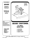
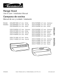
Owner's Manual
10-in. BANDSAW
1/3 HP MOTOR
Model 119.214000
• Table of Contents
CAUTION: Before using this
product, read this manual and
follow all its Safety Rules
and Operating Instructions.
•
•
•
•
•
•
•
Full One Year Warranty
Safety Instructions
Assembly
Getting to Know Your Bandsaw
Adjustment
Operation
Maintenance
• Troubleshooting
• Electrical Schematic
• Parts List
• EspaSol, p. 12
Sears, Roebuck and Co., Hoffman
www.craftsman.com
Estates,
IL 60179, U.S.A.
Table of contents .....................................................................................................................................................................................................
2
Full one year warranty ..............................................................................................................................................................................................
2
Safety instructions ....................................................................................................................................................................................................
2
Assembly. ...................................................................................................................................................................................................................
4
Getting to know your bandsaw ...........................................................................................................
._.
........................................................................ 5
Adjustment ...................................................................................................................................................................................................................
6
Operation ...................................................................................................................................................................................................................
8
Maintenance ..............................................................................................................................................................................................................
8
Troubleshooting ......................................................................................................................................................................................................
9
Electrical schematic ................................................................................................................................................................................................
9
Parts list .............................................................................................................................................................................................................
10
Esparlol ................ .:..........................................................................................................................................
_.......................................................... 12
If this Craftsman tool fails due to a defect in material or workmanship within one year from the date of
purchase, CALL 1-800-4-MY-HOME® TO ARRANGE FOR FREE REPAIR.
If this tool is used for commercial or rental purposes, this warranty will apply for only ninety days from the
date of purchase.
This warranty applies only while this tool is in the United States.
This warranty gives you specific legal rights, and you may also have other rights, which vary, from state to
state.
Sears, Roebuck and Co., Dept. 817WA, Hoffman Estates, IL 60179
GENERAL
SAFETY
WARNINGS
KNOW YOUR POWER TOOL. Read the owner's manual carefully. Learn the tool's applications,
potential hazards!
work capabilities,
and its specific
Always Ground All Tools.
If your tool is equipped with a three-pronged plug, you must plug it into a three-hole electric receptacle. If you use
an adapter to accommodate a two-pronged receptacle, you must attach the adapter plug to a known ground. Never
remove the third prong of the plug.
Always Avoid Dangerous
Environments.
Never use power tools in damp or wet locations.
Keep your work area well lighted and clear of clutter.
Always Remove the Adjusting Keys and Wrenches from Tools after Use.
Form the habit of checking to see that keys and adjusting wrenches are removed from the tool before turning it on.
Always Keep Your Work Area Clean. Cluttered areas and benches invite accidents.
Always Keep Visitors Away from Running Machines.
All visitors should be kept a safe distance from the work area.
Always make the Workshop Childproof.
Chlldproof with padlocks, master switches, or by removing starter keys.
@
Never operate a tool while under the influence of drugs, medication, or alcohol.
AlwaysWearProperApparel.
Never wear loose clothing or jewelry that might get caught in moving parts. Rubber-soled footwear is
recommended for the best footing.
Also use a,face or dust mask if the cutting operation is dusty.
Always Use Safety Glasses and Wear Hearing Protection.
j,_
Never Overreach.
Keep your proper footing and balance at all times.
Never Stand on Tools.
Serious injury could occur if the tool is tipped or if the cutting tool is accidentally contacted.
Always Disconnect Tools.
Disconnect tools before servicing and when changing accessories such as blades, bits, and cutters.
Always Avoid Accidental Staring.
Make sure switch is in "OFF" position before plugging in cord.
Never Leave Tools Running
_
Always Check for Damaged Parts.
I_,
_PECIAL
1.
2.
3.
4.
5.
6.
7.
8,
Unattended.
ir
will operate properly and perform its intended function. Check for alignment of moving parts, binding of moving
Before breakage
parts,
initial or continual
of parts, mounting,
use of the and
tool, any
a guard
other or
conditions
other partthat
thatmay
is damaged
affect its operation.
should be Achecked
guard or
to other
assure that
damaged parts should immediately be properly repaired or replaced.
SAFETY
RULES
FOR BANDSAWS
Always stop the Bandsaw before removing scrap pieces from table.
Always keep hands and fingers away from the blade.
Never attempt to saw stock that does not have a flat surface, unless a suitable support is used.
Always hold material firmly and feed it into the blade at a moderate speed.
Always turn off the machine if the material is to be backed out of an uncompleted cut.
Check for proper blade size and type for thickness and type of material being cut.
Make sure that the blade tension and blade tracking are properly adjusted.
Make "relief" cuts before cutting long curves.
9. Release
blade tension when the saw will not be used for a long period of time.
10. Note and follow the safety warnings and instructions that appear on the lower door.
1. TOOLS
REQUIRED
FOR ASSEMBLY
LIST OF LOOSE PARTS
Item
Item
Description
IN BAG
Description
Q'ty.
Q'ty.
Blade Tension Knob ............................................ 1
Medium Screwdriver .............................. 1
Adjustable Wrench................................. t
Square ..................................................... 1
Miter Gauge ...........................................................1
Hex. Socket Head Cap Screw M6x30 ............... 1
2. UNPACKING
AND
CHECKING
Model 119.214000
one box.
10" Bandsaw
CONTENTS
is shipped
complete
Washer6 ...............................................................1
in
a. Separate all parts from carton and check each item with "Table
of Carton Contents" to make sure all items are accounted for,
before discarding any packing material.
Wing Nut M6..........................................................1
b. Remove the protective oil that is applied to the table. Use any
ordinary house hold type grease and spot remover.
Hex. Bolt M6x12 ....................................................4
c. Apply a coat of paste wax to the table to prevent rust. Wipe all
parts thoroughly with a clean dry cloth.
Lock Washer6 ....................................................4
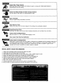
CARTON CONTENTS
Item
A
B
C
D
E
F
G
Description
Q'ty.
Main Machine .................................................................. 1
Fence Assembly. .............................................................. 1
Table....................................................................................1
Guide Rail ....................................................................... 1
Owner's Manual ............................................................. 1
Upper Table Trunnion Assembly. .................................... 1
Bag of Loose Parts ........................................................ 1
Star Knob Screw...................................................2
Washer6 ...............................................................
2
..._J
M3 Hex %" Wrench ..............................................1
=====_=_
M 5He x" L" Wrench ..............................................1
2. INITIAL
A'
E
!
B
F
ASSEMBLY
C
The machine is supplied partly assembled. Prior to use, the
following items have to be installed: Table, Blade Tension Knob
and Rip Fence.
D
WARNING:
To Avoid injury, do not attempt to run or use this
machine until all parts are assembled and working properly.
G
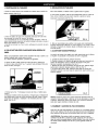
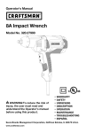
a. Assemble the upper table trunnion to the lower table trunion with
Carriage Bolt, Glide Piece, Washer and Wing Nut. Place the table
on to the upper table trunnion, taking care when passing the saw
blade through the slot of the table (See Fig. 1).
Locate four hex bolts and four lock washers from the bag of loose
parts. Mount the table to the upper table trunnion and install a bolt
with washer in each hole, then tighten with adjustable wrench.
d.Place
thebladetension
knobontothebladetensioner
(See
Fig.4).
b.Fasten
theguiderailwithtwoeachstarknobscrewandwasher
tothetable.Usethehexsocketheadcapscrew,
washerandwing
nutforcorrecting
theworking
tableflatness.
(SeeFig.2)
FIG, 4
e. To ensure sufficient upright stability of the machine it should be
bolted to floor, bench or worktable. For this purpose 6mm holes
are provided in the machine's base. (See Fig. 5)
FIG. 2
FIG. 5
c. Lay the rip fence onto the guide rail. Adjust the rip fence parallel
to the saw blade. Tighten rip fence handle by pressing downward.
(See Fig. 3)
f. The bandsaw has a 2-1/2" dust port included. (Sea Fig. 6)
It is recommended that when in use, the bandsaw is connected to
a suitable dust collector.
!"
FIG. 6
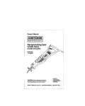
tension knob
=g knob
T
_Blade
rack ng knob
'Guide post adjusting knob
]uide
_. _
Look
Lower tabl
Dust
,
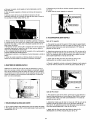
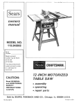
1. CENTERING
THE
3. TILTING
TABLE
THE
TABLE
For bevel cuts, the table tilts 0 through 45 degrees.
a. Loosen the four hex.,bolts mounting the table to the upper table
trunnion. (See Fig. 7)
a. To tilt the table, loosen the wing nut on the table trunnion, set the
table to the required angle and tighten the wing nut again (See Fig.
10).
FIG, 7
b, Move the table sideways as required, until the saw blade runs
through the center of the table insert.
c. ft the adjustment of "b" is not enough to center the table, loosen
!he four flange nuts holding the lower table trunnion and move the
tabie sideways to place the table in the center.
d. Re-tighten hex. bolts for trunnion, recheck the saw blade
position.
FIG. 10
b. It is recommended to verify the correct angle setting using an
angle guide, or by making trial cuts in scrap wood. Adjust the
indicator accordingly by using a phillips head screwdriver.
4. ADJUSTING
2. SETTING
TABLE
SQUARE
THE
RIP FENCE
TO SAW BLADE
The locking pressure of the rip fence has been factory-set, if
adjustment is required proceed as follows:
Loosen the wing nut on the lower table trunnion and place a
suitably sized square against the saw blade. If the table requires
adjustment, proceed as follows:
a. Raise the fence handle to horizontal position.
b. Turn the fence handle clockwise to increase clamping pressure,
counterclockwise to decrease clamping pressure.(See Fig. 11)
c. After counterclockwise truning the fence handle, sliding the rip
fence to the desired position on the guide raiL(See Fig. 11)
d. The fence handle has a cam action, press down the handle to
stamp tightly to the table after setting rip fence to desired position.
a. Using a wrench, release the hex. nut on the frame. (See Fig.8)
b. Place the wrench on the hex. bolt and adjust until the table
square to the saw blade.(See Fig.8)
FIG. 8
c. Tighten the hex. nut and recheck the saw blade and the table for
squareness.
d. Lock the table into position and check that the indicator reads
zero degree on the side of lower table trunnion. Loosen the screw
securing the indicator and reset if necessary to give zero degree
reading. (See Fig. 9)
I
FIG. lt
NOTE: Do not adjust the fence handle such that excessive
pressure is exerted during operation - this may lead to deformation
of the end clamp at the rear of the rip fence. Set the fence handle to
apply just enough pressure to enable safe operation during
cutting.
5. CHANGING
AND ADJUSTING
THE SAW BLADE
This bandsaw is factory-equipped with a general-purpose wood
cutting blade, the saw blade is set prior to delivery.
To change the saw blade, the following procedure must be
followed:
6
WARNING:
To avoid injury from unexpected starting, whenever
changing the saw blade or carrying out adjustments, switch the
handsaw off and remove the power cord from the main outlet. To
avoid injury to hands when handling the saw blade, wear gloves
whenever necessary.
a.Remove
theripfence,theguiderail,thewingnutandscrew
c. Setthebladeguidetotherequired
heightbyturning
theguide
fromthetable.
postadjusting
knob.
b.Opentheupperandlowerdoorsbytuming
thedoorlocking
d.Tighten
thewingnutaftersetting.
knobs.
c.Loosen
thebladetension
byturning
thebladetensionknobon
thetopoftheupperwheelhousing
counterclockwise
untilthesaw
Guide post adjusting knob
bladehasslackened
(viewed
fromabove)(SeeFig.12).
FIG. 14
8. ADJUSTING
d. Remove the saw blade from the upper and lower wheels.
e. When fitting the new saw blade ensure the blade teeth are
pointing downwards and towards you at the position where the
saw blade passes through the table.
f. Re-tension the new saw blade and check the saw blade tracking
by turning the upper wheel by hand. The saw blade should run in
the center of the bandsaw wheels.
g. If need adjust the tracking of the saw blade, proceed as mentioned below" TRACKING THE SAW BLADE"
h. Replace the rip fence, the guide rail, the wing nut and screw to
the table.
THE BANDSAW
BLADE
GUIDES
The Upper Blade Guide
a. To adjust the upper blade guides, first position the right and left
roller guides relative to the blade by slackening the ratcher handle
Fig.15 and moving the guide carrier until both roller guides are
approximately 1/16" behind the gullets of the saw blade.
b. Set both roller guides to within 1/32" of the saw blade by
releasing the guide adjusting screw (A) Fig. 15 on each side of the
saw blade. Do not set the roller guides too close as this will
adversely affect the life of the saw blade.
i. Close the upper and lower doors by turning the door locking
knobs before reconnecting the power supply.
6. TRACKING
THE
c. Adjust the rear roller guide to be just clear of the back of the saw
blade by unlocking the guide adjusting screw (B) Fig. 15
BLADE
d. When the correct adjustment is reached, lock the rear roller
guide in position with the guide adjusting screw (B) Fig.15
Set the tracking of the saw blade before setting the blade guides.
Once the saw blade is installed and tensioned, track the saw
blade by adjusting the tracking knob by hand (See Fig. 13). The
saw blade should run in the center of the bandsaw wheels. When
the correct adjustment is achieved lock the tracking knob with the
wing nut.
Ratchet handle I
Guide adjusting
screw (B)
"
I
Guide adjusting
screw (A)
FIG, 15
The Lower Blade Guide
Tracking knob I
7. SETTING
THE
CUTTING
|
FIG. 13
a. To adjust the lower blade guides, first position the right and left
roller guides relative to the blade by slackening the lock nut Fig.16
and moving the guide carrier until both roller guides are approximately 1/16" behind the gullets of the saw blade
HEIGHT
b. Set both roller guides to within 1/32" of the saw blade by
releasing the guide adjusting screw (C) Fig. 16 on each side of the
saw blade. Do not set the roller guides too close as this will
adversely affect the life of the saw blade.
a. The upper blade guide should be set as close as practical
against the workpiece.
b. To adjust this height, loosen the wing nut at the side of the upper
wheel housing. (See Fig. 14)
c. Adjust the rear roller guide to be just clear of the back of the saw
blade by unlocking the guide adjusting screw (D) Fig, 16
7
d. When the correct adjustment is reached, lock the rear roller
guide in position with the guide adjusting screw (D) Fig.16
Guide adjusting
screw
9. CHANGING
THE
DRIVE
(C)
c. Using a clip pliers (not provided) remove the retaining ring from
the center of the lower wheel.
d. Carefully slide the lower wheel forward and at the same time
release the saw blade from this wheel.
e. Remove the old drive belt and fit the new belt. (ensure ribs in
drive belt are seated correctly before reassembling and tensioning
the drive belt)
f. Follow procedures for CHANGING AND ADJUSTING THE SAW
BLADE & TRACKING THE BANDSAW BLADE, before restoring
power to the bandsaw and setting up for use.
BELT
a. Release the saw blade tension by turning the blade tension
knob on the top of bandsaw counterclockwise.
b. Using a M6 hex. "L" wrench (not 15rovided) to release the hex.
socket head cap screw on motor mounting flange. (See Fig. 17)
WARNING: Before starting check if any part of your bandsaw is
missing, malfuctioning,
has been damaged or broken.., such as
the motor switch, or other operation control, a safety device or the
power cord, turn the bandsaw off and unplug it until the particular
part is properly repaired or replaced.
For best results the saw blade must be sharp. Select the right saw
blade for the job, depending on_tthe thickness of the wc.od the cut to
be made. The thinner and harder the wood, the finer the teeth of
the saw blade. Use a fine tooth blade for cutting sharp curves.
The machine
make straight
pushing it, as
saw blade to
The saw blade cuts on a continuous downstroke, To avoid injury
when hands are unavoidably near to the saw blade, they should
be placed on either side of the blade, not in line with it. Use a
push stick whenever possible when working in close proximity to
the saw blade.
is especially suited for cutting curves, but will also
cuts. Do not attempt to turn the workpiece without
this may cause the workpieee to get stuck, or the
bend.
The rip fence is to enable safe and accurate straight cuts of the
workpiece, usually in the same direction as the grain of the timber.
Start the bandsaw by turning the lock switch on and wait for the
bandsaw to come to full speed before starting to cut. Never start
the bandsaw with the workpiece in contact with the saw blade.
The miter gauge is to enable safe and accurate crosscut of the
workpiece.
The tiltable table is used for bevel cuts.
Slowly feed the workpiece towards the saw blade, putting only light
pressure on it. With both hands, firmly hold the workpiece down on
the table, and feed it towards the saw blade slowly.
WARNING: When sawing with the rip fence and a tilted table, the rip
fence must be installed on that side of the table which is tilted
downward.
WARNING:
To avoid injury due to unexpected starting, before
cleaning or carrying out maintenance work, switch off and disconnect the bandsaw from the power source.
Regular maintenance
problems.
of the bandsaw will prevent unnecessary
a. Keep the table clean to ensure accurate cutting.
b. Keep the outside of the machine clean to ensure accurate
operation of all moving parts and prevent excessive wear.
c. Keep the ventilation slots of the motor clean to prevent it from
overheating.
d. Keep the inside (near the saw blade, etc.) clean to prevent
accumulation of dust. Use dust collection if possible.
e. To prolong the life of the saw blade, when the bandsaw is not in
use for extended periods, release the saw blade tension. Before
reusing the bandsaw ensure that the blade is re-tensioned and
tracking is checked.
Never use water or other liquids to clean the bandsaw. Use a dry
brush.
8
Problem
Diagnosis
Remedy
The machine does not work when
switched on.
1. No power supply.
2. Defective switch.
3 Defective motor.
1. Check the cable for breakage.
2. Replace the lock switch.
3. Defective motor.
The saw blade does not move with the
motor running.
1. The blade tension knob has not been
tightened.
2. The blade has come off one of the
wheels.
3. The saw blade has broken.
4. The drive belt has snapped.
1. Switch off the motor, tighten the blade
tension knob.
2. Open the doors and check.
1. Rip fence for cutting not used.
2. Feed rate too fast.
1. Use a rip fence.
2. Put light pressure on the workpiece.
Make sure the saw blade does not bend,
3. Try a new saw blade.
4. Adjust the blade guides (see ADJUSTMENT instructions).
The saw blade does not cut in a straight
line.
3. Replace the blade.
4. Replace the belt.
3. The blade teeth are dull or damaged.
4, Blade guides not suitably adjusted.
The saw blade does not cut, or cuts very
slowly.
1. The teeth are dull, caused by cutting
hard material or long use.
1. Replace the saw blade, use a 6 "EEl.
saw blade for wood and soft material.
Use a 14 T.P.L saw blade for harder
materials. A 14 "EEl. saw blade always
cuts slower due to the finer teeth and the
slower cutting performance.
2. Fit the saw blade correctly.
2. The saw blade was fitted the wrong
way on the bandsaw.
Sawdust builds up inside the machine,
This is normal
Clean the machine regularly. Open the
doors and remove the sawdust with a
vacuum cleaner.
Sawdust
This is normal
Clean the ventilating slots of the motor
with a vacuum cleaner. From time to time
remove the sawdust to prevent it from
being drawn into the housing.
1. The table is not at right angles to the
blade.
2. The saw blade is dull or too much
pressure was put on the workpiece.
1. Adjust the table.
1. The wheels are not in alignment or
defective bearing.
2. The blade tracking knob hasn't been
properly adjusted.
3. Inferior saw blade.
1. Replace bearing.
inside the motor housing.
The machine does not cut at 45 or 90
degrees.
The saw blade can not be properly
positioned on the wheels.
2. Replace the saw blade or put less
pressure on the workpiece.
2. Adjust the blade tracking knob (See
ADJUSTMENT instructions).
3. Replace the saw blade.
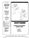
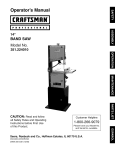
W.b_r,INING: This machine must be grounded. To avoid electrocution or fire, any repairs to electrical system should be done only by a
Cdalified electrician, usin genuine replacement parts.
SWITCH
I
MOTOR
PLUG
_L
\
1N
KEYNO.
1
2
3
4
5
6
7
8
9
10
11
12
13
14
15
16
17
18
19
20
21
22
23
24
25
26
27
28
29
30
31
32
33
34
35
36
37
38
39
40
41
42
43
44
45
46
47
48
49
5O
51
52
53
54
55
56
57
58
59
6O
61
62
63
64
65
66
67
68
69
7O
71
72
73
74
75
76
77
78
79
8O
81
82
DESCRIPTION
Door locking knob Cap
Hex. Bolt M6x45
KEYNO.
83
84
85
86
87
88
89
9O
91
92
93
94
95
96
97
98
99
100
101
102
103
104
105
106
107
108
109
110
111
112
113
114
115
116
117
118
119
120
121
122
123
124
125
126
127
128
129
130
131
132
133
134
135
136
137
138 '
139
140
141
142
143
144
145
146
147
148
149
150
151
152
153
154
155
156
157
158
159
160
161
162
163
Door locking knob body
Hex. Nut M6
Slotted Insert
Special Spring Washer 10
Lock Housing
Upper Door
Rivet 4x8
Leaf Spring
Special Nut M22
Tongue Lock
Spring Washer 6
Lock Nut M6
Blade Tension Knob Cap
Blade Tension Knob Body
Blade Tensioner
Washer 8
Flange Nut M6 .
Carriage Bolt M8x50
Bushing Ring
Top Plug
Frame
Hex. Bolt M6x12
Lock Nut M6
Washer 6
Gear
Special Spring Washer 8
Tube
Plastic Nut M20
Adjusting Knob Body
Adjusting Knob Cap
Blade Tracking Knob Cap
Blade Tracking Knob Body
Hex. Bolt M6x60
Hex. Nut M6
Wing Nut M6
Washer 6
Tapping Screw ST3.5x13
Rack
Slider
Carriage Bolt M8x20
Bolt Guide
Wing Nut M8
Blade Guide
T-nut M6
Hex, Bolt M6xl0
T-nut M6
Washer 6
Hex. Socket Set Screw M6x25
Ratchet handle
Guide Adjust Screw
Bail Bearing 6ram
Washer 6
Bearing Mount Cylinder
Hex. Socket Set Screw M6xl0
Upper Guide Mount
Upper Guide Shaft
Bearing Mount Cylinder w/Cap
Upper Guide Body
Carriage Bolt M6x30
Glide Piece
Upper Table Trunion
Lock Washer 6
Hex. Bolt M6x12
Lower Table Trunion
Carriage Bolt M6x16
Wing Nut M6
Washer 6
Flange Nut M6
Indicator
Tapping Screw ST3.5x9.5
Table
Table Insert
Hex. Socket Head Cap Screw M6x30
Washer 6
Wing Nut M6
Fence Clamper
Threaded Rod
Spring
Rod Guide
Fence
11
DESCRIPTION
•
Flat Countersunk
Rod Guide
Guide Rail
Fence Carrier
Head Screw M6x1O
,Special Screw
Washer 10
Fence Handle
Roll Pin 3x18
Star knob screw
Washer 6
Aluminium Bar
Miter Gauge Base
Indicator
Pan Head Screw M5x6
Knob
Bearing Mount Cylinder
Hex. Socket Set Screw M6xlg
Lower Guide Body
Lower Guide Shaft
Lower Guide Mount
Lock Nut MB
Washer 6
Washer 6
Hex. Bolt M6x20
Guide Adjust Screw
Ball Bearing 6ram
Guide Key
Washer 6
Lock Nut M6
Spring Washer 6
Tongue Lock
Special Nut M22
Lower Door
Leaf Spring
Rivet 4X8
Lock Housing
Special Spring Washer 10
Slotted Insert
Hex. Nut M6
Door locking knob Body
Hex. Bolt M6x40
Door locking knob Cap
Hex. Socket Head Cap Screw M8x3O
Spring Washer 8
Washer 8
Motor
Hex. Bolt M6x20
Hex. Nut M6
Lower Bearing Bolt
Hsx. Nut M14
Motor PuUey
Hex. Socket Set Screw M6xlO
Drive Belt
Ball Bearing 12ram
Retaining Ring 28
Lower Wheel
Tire
Retaining Ring 12
Saw Blade
Upper Wheel
Upper Bearing Bolt
Wheel Carrier Bracket
Hex. Nut M14
Star Lock
Mount Shaft
Blade Tensioner
Carriage Bolt M8x65
Brush Strip
Flange Nut M8
'Hex, Bolt M6x35
Hex. Nut M6
Cable w/Plug
Lock Washer 4
Washer 4
Pan Head Screw M4x8
Switch Cover Plate
Lock Switch
Pan Head Screw M4x12
Tension Bracket
Rubber Tube
Washer 8
Tebla
decontenidos
........................................................................................................................................................
12
Tede
elalecongarantia
..................................................................................................................................................
12
Instruceienes
deseguridad
.................................................................................................................................................
12
Ensamblaje
..................................................................................................................................................................
14
Conocer
tusierradecinta
.................................................................................................................................................
15
Aiustacien
...................................................................................................................................................................
16
OperaciSn
...................................................................................................................................................................
18
Mantenimiente
..............................................................................................................................................................
18
SoluciSn
deProblemas
.....................................................................................................................................................
19
Esquema
el_ctdco
.........................................................................................................................................................
19
Listadepartes
..............................................................................................................................................................
10
EspaSol
......................................................................................................................................................................
12
En esta herramienta de artesano falla debido al defecto en material o habilidad dentro de un afro desde
la fecha de compra, Ilamar al 1-800-4-MY-HOME® para ORGANIZAR LA REPARACION GRATUITA.
En esta herramienta es utilizado para los pr6positos comerciales o de alquiler, este garantia se aplicara
por solo noventa d[as desde la fecha de compra.
Este garantia se aplica solo cuando esta herramienta est_ en Estados Unidos.
Este garantia te da los derechos legales espec{ficos, y usted tambien puede tener otros derechos, por el
cual varia, desde un estado al otro estado.
Sears, Roebuck y Co, Dept 817 WA, Hoffman Estates, IL 60179
ADVERTENCIA
GENERAL
DE SEGURIDAD
SABER TU HERRAMIENTA DE PODER: Leer el manual de usuarioeuidadesamente.Aprender las aplieeeionesde herramienta, capacidadde
trebajo, y sus riesgos de potenciaespeeffico.
Siempre Todos los Herramientas
en Tierra.
Si tu herramiente esta equipada con enchufe de tres-puntas, usted debe enchufarlo dentro de un recipiente electrice de trespuntas. Si usted utilize un adaptador pare acemodarlo a un recipiente de dos-puntas, usted debe agarrar e! enchufe de
adaptador a tierra. Nunca remover la tercera punta del enchufe.
Siempre evitar los peligros
Nunca utilizar les herramientas
ambientales.
en sities ht_medes o mojados.
Mantener tu area de trabajo bien iluminado
y fuera de deserden.
Slempre Remover les botones de ajuste y arranque de los herramientas
luego del uso.
Fermar el costumbre de chequear que les botones y aiuste de arrenque estan removidos de1 herramienta
Siempre
guarder
tu area de trabajc
limpio.
Areas y escriterios
deserdenados
puede'causar
antes de encenderlo.
accidentes.
Slempre mantener los vlsltados
fuera del corrido de las m_quinas.
Todos los visitores debe rnantener una distartcia segura desde el aree de trabejo.
Siempre hacer el taller de prueba de los ainos
Prueba de los niSos con les candados, enchufes de maestro, e pot quitanza
de las ILaves de cornienzo.
F_l=lll[e] t3[e3
@
Nunca operar
alcohol.
lee herramientas
cuando
estd bajo de la Influencla
12
de las drogas,
medlcamentos
o
ft_l[dl=lni[e];_J
Siempre poner le ropa aproplada.
Nunca no poner la rope o joyerias que puede agarrar en partes movidas.
Caueho-exclusivo de ealzado estd recornendado pare un calzado mejor.
_"yl;,i=1m[e']z{e]
Tambien utilizar la m_.scara de care o de poLvo sila operacibn de sorts est& empolvado.
Slempre uUlizar las gafas de seguridad y poner la protecibn de oido.
WNI_ =ill [e']z{e]
Nunca ir demasiado
lejoe,
Mantener tu calzado apropiado
y equilibrar todo los tiempos.
Nunce pararse sobre herramientas.
Puede ocurrir danes severos si el herramienta esta emboquillado
accidentalmente.
Siempre
desconectar
los herramientae.
Desconectar los herramientas antes de servicio y cuando cambia
Asegurar
Siernpre
_
!_lp
f
los accesorios
tal come file, broca, y cortantes.
que
el enchufe
est& endeposici6n
"OFF" antes de enchufarlo dentro del cordon,
eviter
el comienzo
accidente.
NARCS dejar
Siempre
o si el herramiente de sorts est_ conectada
corrido
chequear
de los
herramientas
por partes
asegurar que _ste operara
Las
partes
movidas,
rupture
Antes
de initial
o continuar
otras partes dariados debe
descuidados.
daSados.
apropiadamente
y realiza sue funciones deseados. Chequear por alineeciSn de partes rnovidas, atar
partes,
montado,
y cualquier
otros ocondiciones
puede
afectar
operaciones.
guardia c
elde use
de los
herramientas,
la guardia
otras partesque
esta
dariado
debe sue
estar
chequeado Lapara
ser reparados o reemplazados apropiados inmediatamente.
REGLAS ESPECIALES DE SEGURIDAD PARA SIERRA DE CINTA
1.
2.
3.
4.
5.
6.
7.
8.
Siempre parer la sierra de cinta antes de remover los fragmentos de las piszas de la mesa.
Siempre mantener los manos y los dedos fuera del filo.
Nunca intenta de sierra el patrSn que no tiene superficie piano, a no ser que utilize un soporte apropiado.
Nunca mantener el material firmemente y alimentarlo dentro de filo ala velocidad moderado.
Siernpre epagar la mg=quina si el material est', retirado fuera de un corte incomplete.
Chequear para un tamario de filo apropiado y tipos de espesor y tipos de material cortado.
Asegurar que la tension de file y pista de filo est&n ajustados apropiadamente.
Hacer cortes "alivio" antes de cortar curves largos.
9.
10.
Liberar la tension de filo cuendo
Anotar y seguir las advertencias
el sierra no serd utilizado por un periodo largo.
e instrucciones de seguridad que aparece sobre la puerta mas bajo.
13
1. Herramienta
requerido
LISTA DE PARTES
para el ensamblaje
Item
Item
Descripci6n
Destornillador
SUELTOS
EN EL PAQUETE
Descripci6n
Cantidad
Cantldad
Bot6n de tensi6n de filo ................................
1
Medidor ..........................................................
1
Enchufe Hex M6x 30 .....................................
1
mediano .............................. 1
Llave ajustable ..........................................
1
Cuadrado ..................................................
1
2. Desemblaje y chequeao de los contenidos
Modelo
119.214000
10" Cinta de sierra est& embarcado
completamente
Arandeia 6 ......................................................
1
Tuerca de ala M6 ...........................................
1
Rorlo Hex M6x12 ............................................
4
en una caja
a. Separar todas las partes del cart6n y chequear eada item con "posible
T de los Contenidos Carton" para asegurar que todos los items est&n
contados antes de descargar ninguna material del paquete.
b. Remover el aceite protector que est& aplicada para la mesa. Utilizar
algt3n agarro familiar tipo grasa y removedor.
c. Aplicar uea oapa de pasta de cera pare la mesa por la prevenci6n de
polvo. Limpiar todas las partes directamente con un pa5o seoo y limpio.
Arandela bloqueado 6 ..................................
4
Comenzar
2
CONTENIDOS DE CARTON
Item
A
8
C
D
E
Descripcibn
Cantidad
Maquina principaF ..................................................
1
Perfil de Asamblaje ...............................................
1
Tabtero .................................................................
1
Guia de Carril .......................................................
!
Manual de Usuario ...............................................
1
F
G
Asamblaje de Mufi6n de tablero superior. ............ 1
Paquete de Partes sueltos ...................................
1
de tirar el tornillo .......................
Arandela 6.................................................... 2
•
J
Llave Hex"L" M3 ........................................
;..1
Llave Hex "L" M5 ...........................................
1
2. EMSAMBLAJE INICIAL
C
La mAquina esta parcialmente ernsamblada. Prioridad para el uso, los item
siguieetes debe estar instalado: Mesa, Bot6n de tension de filo y
desgarrar el protector
D
B
ADVERTENCIA:
ii_i!ii!;i .
I_:L
j
E
pare evitar el daSo, no debe correr o utitizar este
maquina antes de que todas Jas partes estan emsamblado
correctamente,
a. Emsamblar el tablero de mu56n superior con el tablero de mu56n
inferior utilizando tornillo, pieza de ligaduradura, Arandela y ala
excentrico. Ubicar el tablero sobre el tablero de mu56n superior cuidando
euando pasa la cinta de sierra atraves de ranura de la mesa (Ver Fig. t)
Localizar cuatro cerrojo hex y ouatro arandela bloqueada del paquete de
partes sueltos. Montar la mesa para la uniSn de tablero superior e instalar
el cerro)o con arandela en cada agujero, luego ajustarlo con tornillo
ajustable.
;
F
y trabajado
G
14
d, Ubicar bot6n de tension de filo sobre el tensi6n do file (Ver Fig. 4)
b. Ajusiar el guia de carril con dos botones de rosca de comienzo y
arandear al tablero. Utilizer el bot6n hex puntando el troni[Io, arandelar y
balancear
para corregir
el tablero de trabajo.
e. Para asegurar la estabilidad vertical suficiente de la maquina este debe
estar erguido al piso, banco o tabla del trabajo. Pare este prop6sito
agujeros 6ram est&n siempre en la base de la m&quina (Ver Fig 5.)
(Ver Fig. 2)
c. Coloeer el rasg6n acerca sobre el guia de carriL Ajustar el rasg6n
acerca el pararelo ala cinta de sierra. Apretar el rasg6n manejando
presionarlo hacia abajo. (Ver Fig. 3)
f. Esta cinta _Je sierra bene inclubdo puerta de polvo 2-1/2" IVer Fig. 6)
Este es recomendado cuando est& en use, la cinta de sierra esta
conectada al colector de polvo.
tensi6n de file
do bioqueo de puerta
i
! "_ot6n
Gufa de file
Medider
Tablero de
Tablero do
Puerta de
15
._._Bot6n
de pista de file
de ajuste pest guFa
1. CENTRALIZAR
3. INCLINACION DE TABLERO
EL TABLERO
a. Soltar !os cuatro botones hex mantado en el tablero para el mufi6n de
Para cortes biselado, el tablero inclina 0 grados haste 45 grades.
tablero superior. (Ver Fig 7)
a. Pare inclinar el tablero, soltar el tuerca balaneeado sobre el mufi6n de
mesa, ubicar el tablero pare el angulo requerido y apretar el tuerca
balanceado
nuevamente
(Ver Fig. 10)
FIG. 7
b. Mover el tablero de lugar como requerido, haste que sierra de cinta
corre atraves del centre del inserci6n de tablero.
c. Si el ajustaci6n de "b" no es suficiente al centro de tablero, soltar los
cuatro tuercas bridas reteniendo el rnufi6n de tablero mAs baio y mover el
tablero para ubicarlo en el centro.
d. Re-tirar los botones hex. Para munon, rechequear la posici6n de sierra
de cinta.
2. COLOCAR TABLERO CUADRADO PARA SIERRA DE
FIG. 10
b. Este es recomendado pare verificar si el &ngulo est,, correctamente
angulado seleccionado utilizando un gufa de angulo, o por corrido e corte
marcado en fragmento de madera. Aiustar el indicador seg0n per el uso
de tornillo philips.
4. AJUSTE DE RASGON PERISCA
CINTA
Soltar tuerca balanceado sobre mufi6n de tablero mas bajo y ubiarlo aun
tamafio cuadrado justo centre sierra de cinta.
Si el tablero requiere ajustaci6n, proceder los siguientes:
a. Utilizer una Nave, relaiar tuerca hex. Sobre el marco. (VER Fig.8)
b. Ubicar la Ilave sobre bot6n hex. Y ajustarlo haste el tablero forms con
sierra de cinta. (Ver Fig.8)
c. Estirar tuerca hex. Y rechequear
cuadrar.
d. Bloquear
cero grado
asegurando
grado. (Ver
La presi6n de bloqueo del rasg6n cerca esta seleccionado por la fabrics,
si requiere una ajustaci6n, los procesos es come Io siguiente:
a. Levantar la perisca hacia la posici6n horizontal.
b. Cambiar la cerca en la direcci6n del aguja de reloj para incrementar la
presion de abrazadera, eontra la direcci6n de! aguja de reloj para
disminuir la presiSn de abrazadera (Ver Fig.11)
c. Desp0es de girar hacia la direcci6n det aguja de reioj, deslizar rasgon
perisca pare Is posici6n deseada sobre el caril (Ver Fig 11)
d. La perisca tiene acci6n leva, presionar hacia abajo el mango pare
abrazadero estirado ata mesa luego de seleccionar rasgon perisca aun
posiciSn deseedo.
el sierra de cinta y el tablero para
Mango de Perista
el tablero dentro de posici6n y chequear que el indicador lee
sobre el lado de muf6n de tablero rnds bajo. Soltar el tornillo
el indicador y resetearlo si es necesario pare dar a cero
Fig. 9)
NOTA:No
operaci6n.
la perisca.
para estar
FIG. 11
ajustar la perisca con muchas presiones ejeroida durante la
Este puede ]legar a deforrnar el final de abrazadero al levantar
Seleccionar perisca para aplicar con presiones suficientes
seguro durante el proceso de corte.
5. CAMBIAR Y AJUSTAR EL FILO DE SIERRA
Este sierra de cinta esta equipada por la f_.brica con el prop6sito general
de filo corta madera, el filo de sierra estd seleccionado para destribuei6n.
Para carnbiar el filo de sierra, los porcesos deben ser come Io siguiente:
FIG. 9
ADVERTENCIA:
Para evitar el dafio no esperado, siempre'cuando
cambiar el filo de sierra o sacar los ajustes, apagar el sierra de cinta y
sacar el cordSn de energfa desde la salida principal. Para evitar el daflo a
los manos cuando maneja el filo de sierra, poner guantes cuando es
necesario.
16
a. Remover la perisca, el caril guiada, el tuerca balanceada y tornillo
desde el tablero.
b. Abrir las puertas superiors e inferiores per botones de bloqueo de
puertas.
c. Soltar la tensi6n de file per giro del bot6n de tensi6n de file del
ruedecillos superiores con la direciSn de aguja de reloj haste el sierra de
file esta fiojo (vet desde arriba) (Ver Fig. 12).
e. Seleccionar el gufa de file per el altura requerido
post ajuste.
d. Apretar aleta de tuerea despuL_es de selecci6n.
girando el boton de
FIG. f4
8. AJUSTACION DE GUIA DE FILe
d. Remover el sierra de file desde las ruedeciilas superiores e inferiores.
e. Cuando ajusta ei nuevo sierra de file asegurar que el diente de 61o est&
apuntando hacia abajo y hacia usted ala posici6n cuando sierra de file
pasa atraves del tablero.
f. Re-tensioner el nuevo sierra de 61o y chequear sierra de file girando las
ruedecillas superiores per mane.Sierra de file debe recorrer dentro de
centre de ias ruedecillas de sierra de file.
g. Si es necesario de girar sierra de file, procesarlo some menseionado Io
Gufa de file
a. Para ajustar los guias de file superior, Primero lugar los guias derecho
e izquierdo relativamente para el file per aflojar la rueda Fig 15 y mover el
carril guia hasta ambos gulas est_n aproximadamente
1/16" detras de
garganta de sierra de file.
b. Seleccionar ambos gu_as de roller
aflojando el tornUlo de ajuste de guia
de file. No seleccionar guia de roller
afecta desfavorablemente
la vida de
siguiente "RASTREO DE SIERRA DE FILe"
h. Reemplazar la pedsca, el carril guiada, el tuerca balanceada y tornil!o al
tablero.
ii. Cerrar las puertas superiores e infedores girando los botones del
bloqueo de la puerta antes de reconectar el suministro de energfa.
con menos de 1/32" de sierra de file
(A) Fig.15 sobre cada lade de sierra
demasiado cerca debido que 6ste
sierra de file.
c. Ajustar guia de roller para estar clare detras de sierra de file
desbloqueando los tornillos de ajuste de gufa. (B) Fig. 15
d. Cuando la ajustaciSn correcta se encuentra, bloquear el parte posterior
de guia de rueda en posici6n con el tornillo de gufa de ajuste (B) Fig.15
6. RASTREO DE SIERRA DE FILe
Seleccionar el rastreo de sierra
sierra. Una vez que el sierra de
sierra de file ajustando el bot6n
de file debeda correr dentro del
superior
de file antes de seleccionar el gufa de
file est_ instalado y tensionado, rastrear
de rastreo per mane (Ver Fig 13) Sierra
centre de ias ruedecillas de sierra de file.
Cuando la ajustaoi6n est,. correctamente
bot6n con tuerca balanceada.
est_ bloqueado
el restreo del
Tornitlo de gufa
de ajuste (B)
FIG. 15
Guia de File inferior
a. Para ajustar los guias de file inferior, primer lugar los guias derecho e
izquierdo relativamente pare el fi]o per aflojar la rueda Fig.16 y mover el
carril guia haste ambos guias estan aproximadamente
1/16" detras de
garganta de sierra de file.
b. Seleccionar ambos guias de roller con menos de 1/32" de sierra de file
aflojando el tornillo de ajuste de guia (C) Fig.165 sobre cada lade de
sierra de file. No seleccionar guia de roller demasiado cerca debido que
_ste afecta desfavorablemente ta vida de sierra de file.
7. SELECCIONAR ALTURA DE CORTE
a. El file superior debeda estar seleccionado contra las piezas de trabajo.
b. Para ajustar este altura, soltar ia tuerea balanceada al lade superior del
ruedeeilla.(Ver Fig. 14)
c. ajustar guia de roller pare ester clare detras de sierra de file
desbloqueando los tornillos de ajuste de guia. (D) Fig. 16
17
31equear
Tornillo de gufa
de ajuste (C)
FIG. 17
c. Utilizar el alieate (no suministrade)
del ruedecilla inferior.
d. Sacar cuidadosamente la ruedecilla
sierra de file desde este ruedecilla.
9. CAMBIO DE CORREA
el anillo retenido del centro
inferior y al mismo tiempo aflojar
e. Remover correa vieja y ajustar una eorrea nueva. (asegurar la
columna de correa est& correctamente
seteado antes de reuniry
tensionar la correa)
f. Seguir los procesos para CAMBIAR Y AJUSTAR SIERRA DE FILO &
CARRIL SIERRA DE FILO, antes de reiniciar la energia para sierra de filo y
seleecionarlo para el uso.
a. Aflojar ta tension de sierra de filo presionando el botOn de tension de
s_erra sobre el parte superior de sierra de filo en sentido de aguja de
reloj.
b. Utilizar una Ilave hex M6. "L" (no suministrado) para aflojar la cabeza
de Ilave de encaje sobre el reberde de motor. (Ver Fig.17)
Para mejores resultados sierra de file debe estar filoso. Seleccionar
sierra de file correcto para el trabaje, dependiendo sobre el grosor de la
madera el corte hecho. La madera fino y duro, el diente de sierra de file.
Utilizar sierra con diente bueno para cortar en forma de curva.
ADVERTENCIA: Antes de comenzar de chequear si alguna parte de su
s_erra defile est,. perdido, malfuncionado,
est_m daRaclo o roto...tal como
varilla de motor, o otro control de operaciOn, un fuente seguro o el cordon
de energia, apagar sierra de cinta y desenchufarlo hasta que las partes
est&n reparadas o reemplazadas apropiadamente.
Sierra de filo corta carreras continues.
manos est&n inevitablemente
cerca de
ubicado en otro lade del tablero, no en
emujada cuando es posible durante el
de file.
remover
La maquina est& especialmente disefiado para cortar curvas, pero
tambien hace cortes rectos. No pretende de sacar las piezas de trabajo
son empujarlo, come esto puede causar pegado a piezas de trabajo, o
doblar sierra de filo.
Para evitar el da5o cuando los
sierra de filo, ellos debern estar
mismo Ifnea con 61. Utilizar la vara
trabajo para aproxirnarse a sierra
La perista da cortes de piezas de trabajo rectos segura y exacto,
generalmente en misma direcciOn come grano de madera.
Comenzar sierra de cinta girando el boron de bloqueo prendido y esperar
que sierra de filo viene con toda la velocidad antes de comenzar de
cortar. Nunca comenzar sierra de cinta con piezas de trabajo en contacto
con sierra de filo.
El medidor no est& seguro y exacto para eortar los piezas de trabajo.
El tablero inclinado
se usa para cortes biselado.
Lentamente alimentar los piezas de trabajo hacia sierra de filo, poniendo
solamente poca presiOn sobre 61. Con ambos rnanos, firmes mantenidos
en piezas de trabajo hacia el tablero, y alimentado haeia sierra de filo
lentamente.
ADVERTENClA: Cuando junta perisca con tablero inclinade, la perisca
debe estar instalado en otro lado del tablero por el cual estA hacia abajo.
ADVERTENCIA:
Para evitar dare debido a un comienzo inesperado,
antes de limpiar o cargarlo fuera de trabajo, apagarlo y desconectar
sierra de file desde el fuente de energia.
Mantenimiento
inneeesafios.
regular de sierra de filo podr& prevenir problernes
a. Mantener limpio el tablero para asegurar el Corte correcto.
b. Mantener fuera de mAquina limpio para asegurar la operaciOn correcto
de todas las partes moviendo y prevenir cargo excesivo.
c. Mantener ranura de ventilaciOn sobre e] motor, limpiar para prevenirlo
sobrecalentamiento.
Nunca utilizar agua o otro Ifquido para limpiar sierra de file. Utilizar cepillo
ssoo.
d. Mentener el interno limpio (eerca de sierra de filo,etc.) para prevenir
acumulaciOn de polvo. Utilizar coleetor de polvo si es posible.
e. para prolongar la vida de sierra de filo, cuando sierra de cinta no se
utiliza pot un tiempo prolongado, soltar la tension de sierra de file. Antes
de reusar sierra de cinta asegurar que sierra esta chequeado el retension y rastreo.
18
Problema
Diagnostico
Remedio
La m&quina no trabaja cuando enciende.
1. No hay suministro de energia
2. Enchufe defectuoso.
3. Motor defectuoso
1. Chequear el cable dafio
2. Reemplazar el enchufe de bloqueo.
3. Motor defectuoso
1. Bot6n de tensi6n de filo no est& bien
1. Apagar el motor, ajustar el bot6n de tensi6n
de filo.
Sierra de cinta no ser_. removido
motor est& corriendo.
cuando el
Sierra de cinta no corta en Ifnea recta.
ajustado.
2. Sierra sale uno de los ruedecillas.
3. Sierra de cinta esta rota.
4. El corrido de cinta estd estallido
2. Abrir las puertas y chequear.
3. Reemplazar la sierra.
4, Reemplazar la cinta.
1. Perisca para cortar no utilizable.
2. Proporci6n de alimentaeiSn demasiado
rdpido.
1. Utilizar perisca.
2. Poner luz de presi6n sobre pieza de
trabajo. Asegurar que sierra de cinta no est',
doblado.
3. Tratar un nuevo sierra de.cinta.
3. Sierra dentado estd apagado o dafiado.
4. Sierra guiada no estd ajustada
apropiadarnente.
Sierra de cinta no corta, o corta demasiado
lento.
4. Ajustar sierra guiada (vet instrucciones
AJUSTACION)
1. El dentado estd apagador, causado por
corte de material pesado o uso prolongado.
2. Sierra de cinta est_ ajustado en forma
incorrecto sobre sierra de cinta.
Polvo visto dsntro de la m&quina
Esto es normal
de
1. Reemplazar el sierra de cinta_ utilizar el
6T.P.I. sierra de cinta para madera y material
suave• Utilizar el 14 T.P.I. siera de cinta para
material pesado. El 14 ]_P.I. sierra de cinta
siempre corta mas despacio dsbido que el
dentado y forma de corte m_.s ler_to.
2. Ajustar sierra de cinta correctamente.
Limpiar la mdquina regularmente.
Abrir las puertas y remover
un patio de limpiac
el polvo visto con
Po}vo visto dentro del motor de alojamiento.
Esto es normal
Limpiar la ranura de ventilaci6n del motor con
patio de limpiar. Limpiar de vez en cuando
para remover el polvo visto para prevenirlo
que caiga dentro de alojamiento.
La maquina
1.El tablero no estd angulado correctamente al
sie_'ra.
1.Ajustar .,el tablero.
2.Sierra de cinta estd apagado o demaslado
presi6n est_ puesta sobre piesas de trabajo.
2.Reemplazar sierra de cinta o poner menos
presi6n sobre piesas de trabajo.
l.Las ruedecillas no est_n en alineaci6n
maroaci6n defectuoso.
1.Reemplazar
no corta a 45 o 90 grados.
Sierra de cinta no puede estar
apropiadamente
posicionado sobre las
ruedecillas.
2,bot6n de pista de sierra
apropiadamente.
3.Sierra de cinta inferior
o
no estdn ajustada
marcaci6n,
2.Ajustar el boton de pista de sierra (Ver
instrucciones AJUSTACION).
3.Reemplazar sierra de cinta.
ADVERTENClA
: Este mdquina debe estar en tierra. Para evitar electrocusi6n o fuego, todas las reparaciones el_ctricas
solamente por electricistas calificados, utilizando los partes reemplazantes
aut_ntico.
Varilla
Motor
19
deber estar hecho
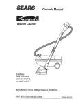
Get it fixed, at your home or ours!
Your Home
For repair-in
your home-of all major brand appliances,
lawn and garden equipment, or heating and cooling systems,
no matter who made it, no matter who sold it!
For the replacement parts, accessories and
owner's manuals that you need to do-it-yourself.
For Sears professional installation of home appliances
and items like garage door openers and water heaters.
1-800-4-MY-HOME
® (1-800-469-4663)
Call anytime, day or night (U.S.A. and Canada)
www.sears.com
www.sears.ca
Our Home
For repair of carry-in items like vacuums, lawn equipment,
and electronics, call or go on-line for the location of your nearest
Sears Parts & Repair Center.
1-800-488-1222
Call anytime,
day or night (U.S.A. only)
www.sears.com
To purchase a protection agreement (U.S.A.)
or maintenance agreement (Canada) on a product serviced
1-800-827-6655
(U.S.A.)
Para pedir servicio de reparaci6n
a domicilio, y para ordenar piezas:
1-888-SU-HOGAR
by Sears:
1-800-361-6665
(Canada)
Au Canada pour service
en fran(;ais:
SM
(1-888-784-6427)
1-800-LE-FOYER
Mc
(1-800-533-6937)
www.sears.ca
Sesir-s
TM
$M
® Registered Trademark /
Trademark /
Service Mark of Sears, Roebuck and Co.
® Marca Registrada / TM Marca de F&bdca / SM Marca de Servicio de Sears, Roebuck and Co.
MCMarque de commerce / MDMarque depos6e de Sears, Roebuck and Co.
© Sears, Roebuck and Co.