1
Command Reference
MODEL :
CT-S280
CT-S300
CT-S2000
CT-S4000
BD2-2220
CT-S310
PMU2XXX
Revision 0.04 2007/8/29
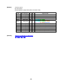
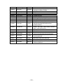
REVISON
Rev No.
Date
Comment
0.00
2006/9/26
Newly isuued
0.01
2006/11/22
Add program sample for FS p and FS q
0.02
2007/2/26
Revised page 153,155,159,169,205-207
0.03
2007/5/21
Supported CT-S310
0.04
2007/8/29
Supported PMU2XXX
CITIZEN is a registered trade mark of CITIZEN HOLDINGS CO., LTD., Japan.
CITIZEN es una marca registrada de CITIZEN HOLDINGS CO., LTD., Japón.
TABLE OF CONTENTS
TABLE OF CONTENTS................................................................................... 3
1. OUTLINE................................................................................................... 9
1.1 OPERATION MODE .........................................................................................................9
1.2 CHARACTER SET .............................................................................................................9
1.3 CONTROL COMMANDS .....................................................................................................9
1.3.1 Control Command Details .................................................................................................9
1.3.2 How to Send Control Commands......................................................................................9
2. CONTROL COMMANDS .......................................................................... 10
2.1 ESC/POS COMMAND LIST .......................................................................................... 10
2.1.1 CT-S280............................................................................................................................ 10
2.1.2 CT-S300/CT-S310........................................................................................................... 13
2.1.3 CT-S2000 ......................................................................................................................... 16
2.1.4 CT-S4000 ......................................................................................................................... 20
2.1.5 BD2-2220......................................................................................................................... 24
2.1.6 PMU2XXX......................................................................................................................... 27
2.2 COMMAND DETAILS .................................................................................................... 30
2.2.1 Description of Items ....................................................................................................... 30
2.2.2 Print Control Commands ................................................................................................ 31
LF...................................................................................................................................................31
CR ..................................................................................................................................................32
FF (At selection of PAGE MODE) ................................................................................................33
FF (valid only for Black mark specification) ..............................................................................33
ESC FF ...........................................................................................................................................34
ESC J n...........................................................................................................................................35
ESC d n ..........................................................................................................................................36
2.2.3 Print Character Commands............................................................................................ 37
CAN................................................................................................................................................37
ESC SP n........................................................................................................................................38
ESC ! n ...........................................................................................................................................39
ESC % n ........................................................................................................................................41
ESC & s n m [ a [p] s x a ] m-n+1 ...............................................................................................42
ESC - n...........................................................................................................................................44
ESC ? n ..........................................................................................................................................45
ESC E n ..........................................................................................................................................46
ESC G n..........................................................................................................................................47
ESC M n .........................................................................................................................................48
ESC R n..........................................................................................................................................49
ESC V n..........................................................................................................................................50
-3-
ESC t n...........................................................................................................................................51
ESC { n ..........................................................................................................................................52
ESC ~ J n (Valid in CBM-270-Compatible Mode)......................................................................53
ESC ~ J n (Valid in CBM1000-Compatible Mode) .....................................................................54
DC3 n (Valid in CBM-270-Compatible Mode)...........................................................................55
DC3 n (Valid in CBM1000-Compatible Mode)...........................................................................56
GS ! n .............................................................................................................................................57
GS B n............................................................................................................................................59
GS b n............................................................................................................................................60
2.2.4 Print Position Commands.............................................................................................. 61
HT ..................................................................................................................................................61
ESC $ n1 n2...................................................................................................................................62
ESC D [n]k NULL...........................................................................................................................63
ESC T n ..........................................................................................................................................64
ESC W xL xH yL yH dxL dxH dyL dyH..........................................................................................65
ESC \ nL nH..................................................................................................................................67
ESC a n ..........................................................................................................................................68
GS $ nL nH ....................................................................................................................................69
GS L nL nH.....................................................................................................................................70
GS W nL nH...................................................................................................................................71
GS \ nL nH ...................................................................................................................................73
2.2.5 Line Feed Span Commands............................................................................................ 74
ESC 2 .............................................................................................................................................74
ESC 3 n ..........................................................................................................................................75
2.2.6 Bit Image Commands..................................................................................................... 76
ESC * m n1 n2 [d] k .....................................................................................................................76
GS * n1 n2 [d] n1xn2x8...............................................................................................................77
GS / m ...........................................................................................................................................78
GS v 0 m xL xH yL yH d1 ... dk.....................................................................................................79
2.2.7 Status Commands........................................................................................................... 81
DLE EOT n .....................................................................................................................................81
ESC u n ..........................................................................................................................................88
ESC v .............................................................................................................................................89
GS a n ............................................................................................................................................90
GS r n.............................................................................................................................................93
2.2.8 Paper Detecting Commands .......................................................................................... 95
ESC c 3 n .......................................................................................................................................95
ESC c 4 n .......................................................................................................................................96
2.2.9 Panel Switch Commands................................................................................................ 97
ESC c 5 n .......................................................................................................................................97
2.2.10 Macro Commands ......................................................................................................... 98
GS : ................................................................................................................................................98
GS ^ n1 n2 n3...............................................................................................................................99
-4-
2.2.11 Cutter Commands....................................................................................................... 100
ESC i ............................................................................................................................................100
ESC m ..........................................................................................................................................101
GS V m ・・・ (1) ...........................................................................................................................102
GS V m n ・・・ (2)........................................................................................................................102
2.2.12 Bar Code Commands .................................................................................................. 103
GS H n..........................................................................................................................................103
GS f n...........................................................................................................................................104
GS h n..........................................................................................................................................105
(1)GS k m [d1...dk] NUL ............................................................................................................106
(2)GS k m n [d1...dn] .................................................................................................................106
GS w n .........................................................................................................................................111
2.2.13 Commands for Non-volatile Memory ........................................................................ 112
GS ( C pL pH m fn b [c1 c2][d1...dk].........................................................................................112
fn=0、48: Function 0 Erasing Specified Record.........................................................................................113
fn=1、49: Function 1 Storing Data to Specified Record.............................................................................113
fn=2、50: Function 2 Sending Data Stored in Specified Record.................................................................114
fn=3、51: Function 3 Sending Use Amount ..............................................................................................115
fn=4、52: Function 4 Sending Remaining Capacity...................................................................................115
fn=5、53: Function 5 Sending Key Code List of Stored Record..................................................................116
fn=6、54: Function 6 Erasing All User NV Memory Area in a Lump............................................................117
GS ( L pL pH m fn [parameter]..................................................................................................118
GS 8 L p1 p2 p3 p4 m fn [parameter].......................................................................................118
fn=0、48: Function 48 Sending NV Graphics Memory Capacity .................................................................119
fn=2、50: Function 50 Printing Graphics Data Stored in Print Buffer..........................................................119
fn=3、51: Function 51 Sending the Remaining Amount of NV Graphics Memory.......................................120
fn=64: Function 64 Sending Key Code List of Defined NV Graphics ..........................................................121
fn=65: Function 65 Erasing All Data of NV Graphics in a Lump.................................................................122
fn=66: Function 66 Erasing Specified NV Graphics Data ...........................................................................122
fn=67: Function 67 Defining Raster Type Graphics Data to NV Memory....................................................123
fn=69: Function 69 Printing Specified Graphics ........................................................................................124
fn=112: Function 112 Storing Raster Type Graphics Data to Print Buffer ..................................................125
GS g 0 m nL nH...........................................................................................................................126
GS g 2 m nL nH...........................................................................................................................127
FS p n m ......................................................................................................................................128
FS q n [xL xH yL yH d1...dk]1...[xL xH yL yH d1...dk]n............................................................130
2.2.14 Kanji Control Commands ........................................................................................... 132
FS ! n............................................................................................................................................132
FS & .............................................................................................................................................133
FS - n ...........................................................................................................................................134
FS ................................................................................................................................................135
FS 2 a1 a2 [d]k ...........................................................................................................................136
FS C n ..........................................................................................................................................138
FS S n1 n2 ...................................................................................................................................140
FS W n .........................................................................................................................................141
FS ( A pL pH fn […].....................................................................................................................142
fn=48: Function 48 Set Kanji fonts...........................................................................................................142
-5-
2.2.15 Black Mark Control Commands ................................................................................. 143
GS FF ...........................................................................................................................................143
GS < ............................................................................................................................................143
GS A m n......................................................................................................................................144
GS C 0 m n...................................................................................................................................145
GS C 1 n1 n2 n3 n4 n5 n6 ..........................................................................................................146
GS C 2 n1 n2 ...............................................................................................................................147
GS C ; n1 ; n2 ; n3 ; n4 ; n5 ;......................................................................................................148
GS c .............................................................................................................................................149
GS l n1L n1H n2L n2H ................................................................................................................150
GS p n..........................................................................................................................................151
2.2.16 Printer Function Setting Commands......................................................................... 152
GS ( D pL pH m [a1 b1]...[ak bk]...............................................................................................152
GS ( E pL pH fn […] ....................................................................................................................153
fn=1: Function 1 Transferring to Printer Function Setting Mode................................................................154
fn=2: Function 2 End of Printer Function Setting Mode.............................................................................154
fn=3: Function 3 Setting Memory Switch Value........................................................................................155
fn=4: Function 4 Sending the Set Memory Switch Value ..........................................................................168
fn=5: Function 5 Setting Customized Value..............................................................................................169
fn=6: Function 6 Sending the Set Customized Value ................................................................................181
fn=7: Function 7 Copying User-defined Page ...........................................................................................193
fn=8: Function 8 Defining Data by the Column Format to Character Code Page of Work Area ..................194
fn=9: Function 9 Defining Data in the Raster Format to the Character Code Page of Work Area................195
fn=10: Function 10 Erasing Data of Character Code Page Data in Work Area ...........................................196
fn=11: Function 11 Setting Communication Conditions ............................................................................197
fn=12: Function 12 Sending the Set Communication Conditions...............................................................198
fn=255: Function 255 Setting All Contents Set by Printer Function Setting Mode to the State at Shipment..199
GS ( K pL pH fn m .......................................................................................................................200
fn=49: Function 49 Setting Printing Density .............................................................................................201
fn=50: Function 50 Setting Printing Speed...............................................................................................202
fn=97: Function 97 Setting Number of Divisions for Head Conducting ......................................................203
GS ( M pL pH fn m ......................................................................................................................204
fn=1、49: Function 1 Copies the set value stored in work area to the storage area ...................................205
fn=2、50: Function 2 Copies the set value stored in storage area to the work area ...................................205
fn=3、51: Function 3 Specifies the auto loading function of the set value at initialization to be valid or invalid
................................................................................................................................................................206
GS ( N pL pH fn m.......................................................................................................................207
fn=48: Function 48 Selects character color...............................................................................................207
2.2.17 2-dimensional code Commands............................................................................... 208
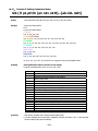
GS ( k pL pH cn fn [parameter] .................................................................................................208
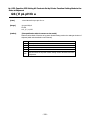
fn=65:
fn=66:
fn=67:
fn=68:
fn=69:
fn=70:
fn=80:
fn=81:
Function 65 Setting the number of digits of PDF417 ...............................................................209
Function 66 Setting the number of steps of PDF417 ...............................................................209
Function 67 Setting module width of PDF417...........................................................................210
Function 68 Setting the height of step of PDF417 ...................................................................210
Function 69 Setting error correction level of PDF417 ..............................................................211
Function 70 Setting Options for PDF417 ...................................................................................212
Function 80 Storing received data to 2-dimensional code data storage area ........................212
Function 81 Printing 2-dimensional code data in 2-dimensional code data storage area .....213
-6-
fn=82: Function 82 Sending the size of 2-dimensional code data in 2-dimensional code data storage
area.........................................................................................................................................................214
fn=65: Function 165 Specifying QRCode model ..................................................................................215
fn=67: Function 167 Sets the module width of QRCode ......................................................................215
fn=69: Function 169 Setting QRCode error correction level ................................................................216
fn=80: Function 180 Storing received data to 2-dimensional code data storage area ......................216
fn=81: Function 181 Printing 2-dimensional code data in 2-dimensional code data storage area ...217
fn=82: Function 182 Sending the size of 2-dimensional code data in 2-dimensional code data storage
area.........................................................................................................................................................218
2.2.18 Other Commands....................................................................................................... 219
DLE ENQ n...................................................................................................................................219
DLE DC4 fn m t (Specification of fn = 1) .................................................................................220
DLE DC4 fn d1...d7 (Specification of fn = 8) ...........................................................................221
ESC = n .......................................................................................................................................222
ESC @ ..........................................................................................................................................223
ESC L ...........................................................................................................................................224
ESC S ...........................................................................................................................................225
ESC p m n1 n2 ............................................................................................................................226
GS ( A pL pH n m ........................................................................................................................227
GS I n...........................................................................................................................................228
GS P x y .......................................................................................................................................235
ESC RS.........................................................................................................................................236
3. CHARACTER CODE TABLE ................................................................... 237
3.1 CODE PAGE .............................................................................................................. 237
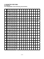
3.1.1 Codepage 00H to 7FH & PC437(USA、Europe Standard) .......................................... 237
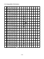
3.1.2 Codepage 00H to 7FH & Katakana .............................................................................. 238
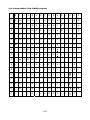
3.1.3 Codepage 00H to 7FH & PC850(Multilingual)............................................................ 239
3.1.4 Codepage 00H to 7FH & PC860(Portuguese)............................................................. 240
3.1.5 Codepage 00H to 7FH & PC863(Canadian-French) ................................................... 241
3.1.6 Codepage 00H to 7FH & PC865(Nordic)..................................................................... 242
3.1.7 Codepage 00H to 7FH & PC852(Easern Europe)........................................................ 243
3.1.8 Codepage 00H to 7FH & PC857(Russian)................................................................... 244
3.1.9 Codepage 00H to 7FH & PC857(Turkish) ................................................................... 245
3.1.10 Codepage 00H to 7FH & PC864(ArabiC)................................................................... 246
3.1.11 Codepage 00H to 7FH & Windows Codepage .......................................................... 247
3.1.12 Codepage 00H to 7FH & Thai code 18 ...................................................................... 248
3.2 INTERNATINAL CHARACTER CODE TABLE ...................................................................... 249
3.3 KANJI CODE TABLE.................................................................................................... 250
3.3.1 JIS non-Kanji................................................................................................................. 250
3.3.2 JIS Kanji Level 1............................................................................................................ 252
3.3.3 JIS Kanji Level 2............................................................................................................ 258
-7-
4. MEMORY SWITCH................................................................................ 265
4.1 MEMORY SWITCHES .................................................................................................. 265
4.1.1 CT-S280.......................................................................................................................... 265
4.1.2 CT-S300.......................................................................................................................... 266
4.1.3 CT-S2000 ....................................................................................................................... 267
4.1.4 CT-S4000 ....................................................................................................................... 269
4.1.5 BD2-2220....................................................................................................................... 271
4.1.6 CT-S310.......................................................................................................................... 272
4.2 DETAILS OF MEMORY SWITCHES ................................................................................ 276
4.2.1 MSW1............................................................................................................................. 276
4.2.2 MSW2............................................................................................................................. 279
4.2.3 MSW3............................................................................................................................. 282
4.2.4 MSW4............................................................................................................................. 285
4.2.5 MSW5............................................................................................................................. 287
4.2.6 MSW6............................................................................................................................. 288
4.2.7 MSW7............................................................................................................................. 289
4.2.8 MSW8............................................................................................................................. 291
4.2.9 MSW9............................................................................................................................. 292
4.2.10 MSW10......................................................................................................................... 293
5. APPENDIX ............................................................................................ 294
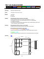
5.1 EXPLANATION ON PAGE MODE ................................................................................. 294
5.1.1 Overview........................................................................................................................ 294
5.1.2 Values Set by Each Command in STANDARD MODE and PAGE MODE..................... 294
5.1.3 Mapping of Print Data in the Print Area ...................................................................... 295
5.1.4 Example of Using PAGE MODE..................................................................................... 297
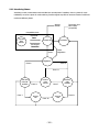
5.2 BIDIRECTIONAL PARALLEL INTERFACE ......................................................................... 301
5.2.1 Parallel Interface Communication Mode .................................................................... 301
5.2.2 Interfacing Phases........................................................................................................ 302
5.2.3 Negotiation .................................................................................................................... 303
5.3 IDENTIFICATION OF SEND STATUS ............................................................................... 310
5.4 CAUTIONS ON BLACK MARK/LABEL PAPER .............................................................. 311
-8-
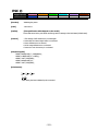
1. OUTLINE
1.1 Operation Mode
Our printer has ESC/POSTM as control commands.
1.2 Character Set
All print data sent from the host computer to the printer are automatically converted to one-byte alphanumeric or
katakana characters (ANK) or two-byte Kanji corresponding to the characters and symbols.
NOTE: For the contents of character set, refer to Character Code Table of this document.
1.3 Control Commands
1.3.1 Control Command Details
Control Commands are used for controlling the operations of the printer such as starting/stopping of printing, line
feeding, paper feeding, etc. They control all functions related to printing, such as type of characters, enlargement
of characters or setting of format.
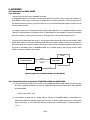
1.3.2 How to Send Control Commands
Some methods are available for sending Control Commands from the host computer to the printer. Here, a
method of sending by BASIC programming is explained.
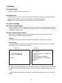
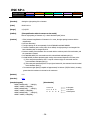
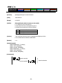
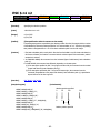
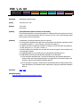
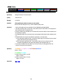
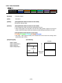
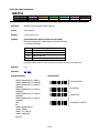
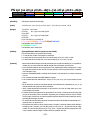
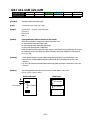
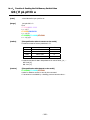
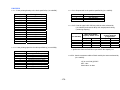
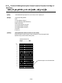
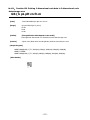
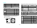
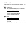
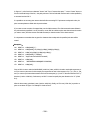
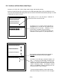
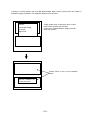
Example 1
Let’s print a character string “CITIZEN” in enlarged (double-height, double-width) and in normal format.
Program coding
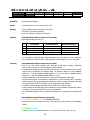
The Control Command shows that the command name for setting the size of a character is GS !. Let’s make a
program using this code. An example is shown below.
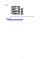
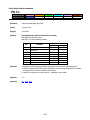
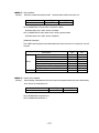
Program List
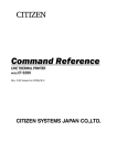
Print Result
10 A$="CITIZEN"
20 LPRINT CHR$(&H1D);"!"; CHR$(&H11);
30 LPRINT A$;
40 LPRINT CHR$(&HA); CHR$(&HA);
50 LPRINT CHR$(&H1D);"!"; CHR$(&H00);
60 LPRINT A$;
70 END
CITIZEN
CITIZEN
In lines 20 and 50, setting and canceling of enlarging a character is sent. As a result, lines 30 and 60 print the same
character string but line 30 prints enlarged characters and line 60 cancels the enlargement and prints in normal
format.
* In this document, sample programs are in BASIC. For details of BASIC programming, refer to the manual for
BASIC.
-9-
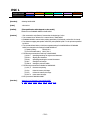
2. CONTROL COMMANDS
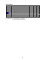
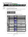
2.1 ESC/POS Command List
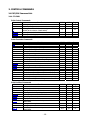
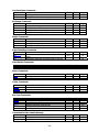
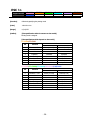
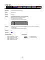
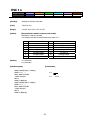
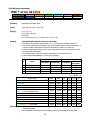
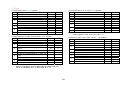
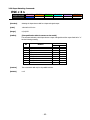
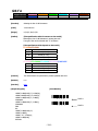
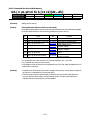
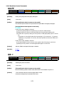
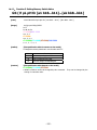
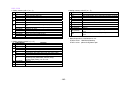
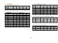
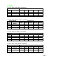
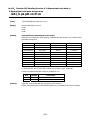
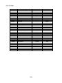
2.1.1 CT-S280
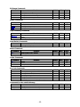
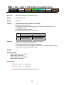
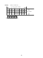
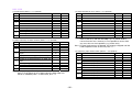
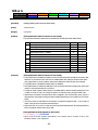
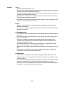
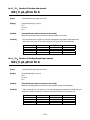
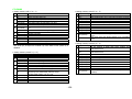
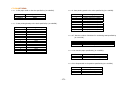
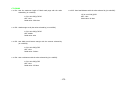
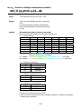
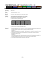
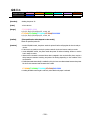
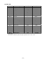
Print Control Commands
Commands
LF
CR
FF
ESC FF
ESC J
ESC d
Function
Printing and paper feed
Back to printing
Printing in PAGE MODE and returning to STANDARD
MODE (at the selection of PAGE MODE)
Printing data in PAGE MODE
Printing and feeding paper in minimum pitch
Printing and feeding the paper by “n” lines
MODE
S・P
S・P
GS P
P
P
S・P
S・P
Page
31
32
33
○
34
35
36
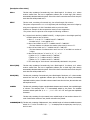
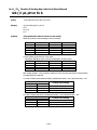
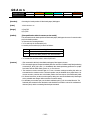
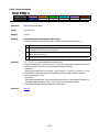
Print Character Commands
Command
CAN
ESC SP
ESC !
ESC %
ESC &
ESC ESC ?
ESC E
ESC G
ESC M
ESC R
ESC V
ESC t
ESC {
ESC ~ J
DC3
GS !
GS B
GS b
Function
Canceling print data in PAGE MODE
Setting the right spacing of the character
Collectively specifying the printing mode
Specifying/Canceling download character set
Defining the download characters
Specifying/canceling underline
Deleting download characters
Specifying/canceling emphasis printing
Specifying/canceling double strike printing
Selection of character fonts
Selecting the international character set
Specifying/canceling 90°-right-turned characters
Selecting the character code table
Specifying/canceling the inverted characters
Specifies/cancels printing in red (black-based paper)
Specifies/cancels printing in red (black-based paper)
Specifying the character size
Specifying/canceling the black/white inverted printing
Specifying/canceling the smoothing
MODE
P
S・P
S・P
S・P
S・P
S・P
S・P
S・P
S・P
S・P
S・P
S
S・P
S
S・P
S
S・P
S・P
S・P
GS P
MODE
S・P
S・P
S・P
P
P
S・P
S
GS P
P
○
69
S
S・P
○
○
70
71
S・P
○
73
○
Page
37
38
39
41
42
44
45
46
47
48
49
50
51
52
53
55
57
59
60
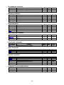
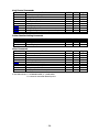
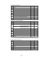
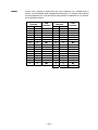
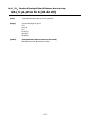
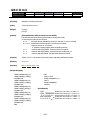
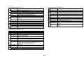
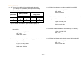
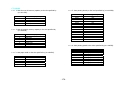
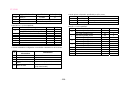
Print Position Commands
Command
HT
ESC $
ESC D
ESC T
ESC W
ESC \
ESC a
GS $
GS L
GS W
GS \
Function
Horizontal tab
Specifying the absolute positions
Setting horizontal tab position
Selecting the character printing direction in PAGE MODE
Defining the print area in PAGE MODE
Specifying the relative position
Aligning the characters
Specifying the absolute vertical position of characters in
PAGE MODE
Setting the left margin
Setting the print area width
Specifying the relative vertical position of a character in
PAGE MODE
- 10 -
○
○
○
Page
61
62
63
64
65
67
68
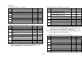
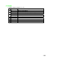
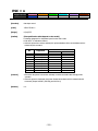
Line Feed Span Commands
Command
ESC 2
ESC 3
Function
Specifying initial line feed rate
Setting line feed rate of minimum pitch
MODE
S・P
S・P
GS P
MODE
S・P
S・P
S・P
S
GS P
Page
76
77
78
79
MODE
S・P
S・P
S・P
S・P
GS P
Page
81
89
90
93
MODE
GS P
Page
○
Page
74
75
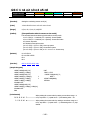
Bit Image Commands
Command
ESC *
GS *
GS /
GS v 0
Function
Specifying the bit image mode
Defining the download bit image
Printing the downloaded bit image
Printing of raster bit image
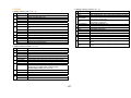
Status Commands
Command
DLE EOT
ESC v
GS a
GS r
Function
Sending status in real-time
Sending Printer status
Enabling/disabling ASB (Automatic Status Back)
Sending status
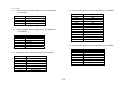
Paper Detecting Commands
Command
ESC c 3
ESC c 4
Function
Selecting the Paper Sensor valid for Paper-end signal
output
Selecting the Paper Near-end Sensor valid for print stop
S・P
95
S・P
96
Panel Switch Commands
Command
ESC c 5
Function
Enabling/disabling the panel switches
MODE
S・P
GS P
Page
97
MODE
S・P
S・P
GS P
Page
98
99
MODE
S・P
S・P
S・P
S・P
S・P
GS P
Page
103
104
105
106
111
MODE
S
S
GS P
Page
128
130
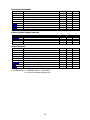
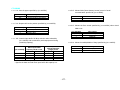
Macro Commands
Command
GS :
GS ^
Function
Starting/ending macro definition
Executing the macro
Bar Code Commands
Command
GS H
GS f
GS h
GS k
GS w
Function
Selecting of printing position of HRI characters
Selecting the font of HRI characters
Specifying the height of the bar code
Printing the bar code
Specifying the horizontal size (magnification) of bar code
Commands for Non-volatile Memory
Command
FS p
FS q
Function
Printing the download NV bit images
Defining the download NV bit image
- 11 -
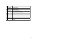
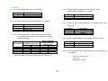
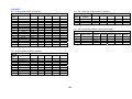
Kanji Control Commands
Command
FS !
FS &
FS FS .
FS 2
FS C
FS S
FS W
FS ( A
Function
Collectively setting Kanji print mode
Setting Kanji mode
Setting/Canceling Kanji underline
Canceling Kanji mode
Defining external character
Selecting Kanji code system
Setting Kanji space amount
Setting/Canceling four times enlargement of Kanji
Setting font attribute of Kanji
MODE
S・P
S・P
S・P
S・P
S・P
S・P
S・P
S・P
S・P
GS P
MODE
S
S
S
S
GS P
Page
153
200
204
207
MODE
S・P
S・P
S・P
S・P
S
P
S
S・P
S・P
GS P
Page
219
221
222
223
224
225
227
228
235
○
Page
132
133
134
135
136
138
140
141
142
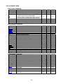
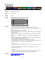
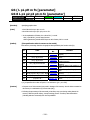
Printer Function Setting Commands
Command
GS ( E
GS ( K
GS ( M
GS ( N
Function
Printer function setting command
Selecting print control method
Customizing the printer
Designating font attribute
Other Commands
Command
DLE ENQ
DLE DC4
ESC =
ESC @
ESC L
ESC S
GS ( A
GS I
GS P
Function
Real-time request to printer
Buffer clear
Data input control
Initializing the printer
Selecting PAGE MODE
Selecting STANDARD MODE
Execution of test printing
Sending the printer ID
Specifying the basic calculation pitch
In the Mode column: S = STANDARD MODE, P = PAGE MODE
O = shows the command affected by GS P.
- 12 -
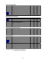
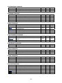
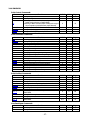
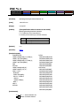
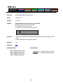
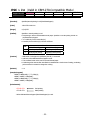
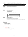
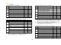
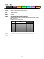
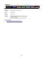
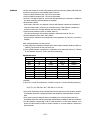
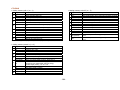
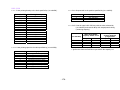
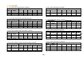
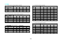
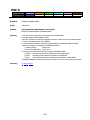
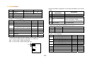
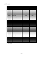
2.1.2 CT-S300/CT-S310
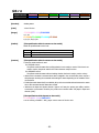
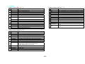
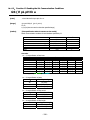
Print Contorl Commands
Command
LF
CR
FF
ESC FF
ESC J
ESC d
Function
Printing and paper feed
Back to printing
(1)Printing in PAGE MODE and returning to STANDARD
MODE (at the selection of PAGE MODE)
(2)Printing of Black mark and paper feeding to the top of
the print position (with Black mark paper selected)
Printing data in PAGE MODE
Printing and feeding paper in minimum pitch
Printing and feeding the paper by “n” lines
MODE
S・P
S・P
GS P
P
P
S・P
S・P
Page
31
32
33
○
34
35
36
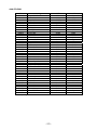
Print Character Commands
Command
CAN
ESC SP
ESC !
ESC %
ESC &
ESC ESC ?
ESC E
ESC G
ESC M
ESC R
ESC V
ESC t
ESC {
ESC ~ J
DC3
GS !
GS B
GS b
Function
Canceling print data in PAGE MODE
Setting the right spacing of the character
Collectively specifying the printing mode
Specifying/Canceling download character set
Defining the download characters
Specifying/canceling underline
Deleting download characters
Specifying/canceling emphasis printing
Specifying/canceling double strike printing
Selection of character fonts
Selecting the international character set
Specifying/canceling 90°-right-turned characters
Selecting the character code table
Specifying/canceling the inverted characters
Specifies/cancels printing in red (black-based paper)
Specifies/cancels printing in red (black-based paper)
Specifying the character size
Specifying/canceling the black/white inverted printing
Specifying/canceling the smoothing
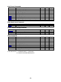
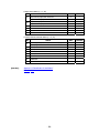
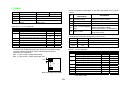
Print Position Commands
Command
HT
ESC
ESC
ESC
ESC
ESC
ESC
$
D
T
W
\
a
GS $
GS L
GS W
GS \
Function
Horizontal tab
Specifying the absolute positions
Setting horizontal tab position
Selecting the character printing direction in PAGE MODE
Defining the print area in PAGE MODE
Specifying the relative position
Aligning the characters
Specifying the absolute vertical position of characters in
PAGE MODE
Setting the left margin
Setting the print area width
Specifying the relative vertical position of a character in
PAGE MODE
- 13 -
MODE
P
S・P
S・P
S・P
S・P
S・P
S・P
S・P
S・P
S・P
S・P
S
S・P
S
S・P
S
S・P
S・P
S・P
GS P
MODE
S・P
S・P
S・P
P
P
S・P
S
GS P
P
○
69
S
S・P
○
○
70
71
S・P
○
73
○
○
○
○
Page
37
38
39
41
42
44
45
46
47
48
49
50
51
52
54
56
57
59
60
Page
61
62
63
64
65
67
68
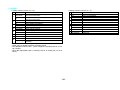
Line Feed Span Commands
Command
ESC 2
ESC 3
Function
Specifying initial line feed rate
Setting line feed rate of minimum pitch
MODE
S・P
S・P
GS P
MODE
S・P
S・P
S・P
S
GS P
Page
76
77
78
79
MODE
S・P
S・P
S・P
GS P
Page
81
90
93
MODE
GS P
Page
○
Page
74
75
Bit Image Commands
Command
ESC *
GS *
GS /
GS v 0
Function
Specifying the bit image mode
Defining the download bit image
Printing the downloaded bit image
Printing of raster bit image
Status Commands
Command
DLE EOT
GS a
GS r
Function
Sending status in real-time
Enabling/disabling ASB (Automatic Status Back)
Sending status
Paper Detecting Commands
Command
ESC c 3
ESC c 4
Function
Selecting the Paper Sensor valid for Paper-end signal
output
Selecting the Paper Near-end Sensor valid for print stop
S・P
95
S・P
96
Panel Switch Commands
Command
ESC c 5
Function
Enabling/disabling the panel switches
MODE
S・P
GS P
Page
97
MODE
S・P
S・P
GS P
Page
98
99
MODE
S・P
S・P
S・P
GS P
Page
100
101
102
MODE
S・P
S・P
S・P
S・P
S・P
GS P
Page
103
104
105
106
111
MODE
S
S
GS P
Page
128
130
Macro Commands
Command
GS :
GS ^
Function
Starting/ending macro definition
Executing the macro
Cutter Commands
Command
ESC i
ESC m
GS V
Function
Full cut
Partial cut
Cutting the paper
○
Bar Code Commands
Command
GS H
GS f
GS h
GS k
GS w
Function
Selecting of printing position of HRI characters
Selecting the font of HRI characters
Specifying the height of the bar code
Printing the bar code
Specifying the horizontal size (magnification) of bar code
Commands for Non-volatile Memory
Command
FS p
FS q
Function
Printing the download NV bit images
Defining the download NV bit image
- 14 -
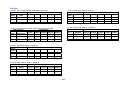
Kanji Control Commands
Command
FS !
FS &
FS FS .
FS 2
FS C
FS S
FS W
FS ( A
Function
Collectively setting Kanji print mode
Setting Kanji mode
Setting/Canceling Kanji underline
Canceling Kanji mode
Defining external character
Selecting Kanji code system
Setting Kanji space amount
Setting/Canceling four times enlargement of Kanji
Setting font attribute of Kanji
MODE
S・P
S・P
S・P
S・P
S・P
S・P
S・P
S・P
S・P
GS P
MODE
S・P
S・P
S・P
S・P
S・P
S・P
S・P
S・P
GS P
Page
143
143
144
145
146
147
148
149
MODE
S
S
S
S
S
GS P
Page
152
153
200
204
207
MODE
S・P
S・P
S・P
S・P
S
P
S・P
S
S・P
S・P
S・P
GS P
Page
219
○
Page
132
133
134
135
136
138
140
141
142
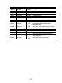
Black Mark Control Commands
Command
GS FF
GS <
GS A
GS C 0
GS C 1
GS C 2
GS C ;
GS c
Function
Printing and ejecting Black mark paper
Initializing the printer mechanism
Correcting the leader position of Black mark paper
Setting the numbering print mode
Setting the numbering counter mode (A)
Setting the numbering counter
Setting the numbering counter mode (B)
Print the counter
Printer Function Setting Commands
Command
GS ( D
GS ( E
GS ( K
GS ( M
GS ( N
Function
Enabling or disabling real-time command
Printer function setting command
Selecting print control method
Customizing the printer
Designating font attribute
Other Commands
Command
DLE ENQ
DLE DC4
ESC =
ESC @
ESC L
ESC S
ESC p
GS ( A
GS I
GS P
ESC RS
Function
Real-time request to printer
Outputting specified pulse in real-time/Buffer clear
Data input control
Initializing the printer
Selecting PAGE MODE
Selecting STANDARD MODE
Generating the specified pulses
Execution of test printing
Sending the printer ID
Specifying the basic calculation pitch
Sound buzzer
In the Mode column: S = STANDARD MODE, P = PAGE MODE
O = shows the command affected by GS P.
- 15 -
220/221
222
223
224
225
226
227
228
235
236
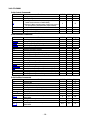
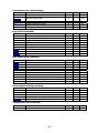
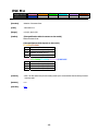
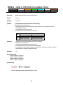
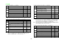
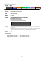
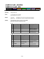
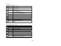
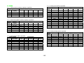
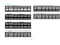
2.1.3 CT-S2000
Print Contorl Commands
Command
LF
CR
FF
ESC FF
ESC J
ESC d
Function
Printing and paper feed
Back to printing
(1)Printing in PAGE MODE and returning to STANDARD
MODE (at the selection of PAGE MODE)
(2)Printing of Black mark and paper feeding to the top of
the print position (with Black mark paper selected)
Printing data in PAGE MODE
Printing and feeding paper in minimum pitch
Printing and feeding the paper by “n” lines
MODE
S・P
S・P
GS P
P
P
S・P
S・P
Page
31
32
33
○
34
35
36
Print Character Commands
Command
CAN
ESC SP
ESC !
ESC %
ESC &
ESC ESC ?
ESC E
ESC G
ESC M
ESC R
ESC V
ESC t
ESC {
ESC ~ J
DC3
GS !
GS B
GS b
Function
Canceling print data in PAGE MODE
Setting the right spacing of the character
Collectively specifying the printing mode
Specifying/Canceling download character set
Defining the download characters
Specifying/canceling underline
Deleting download characters
Specifying/canceling emphasis printing
Specifying/canceling double strike printing
Selection of character fonts
Selecting the international character set
Specifying/canceling 90°-right-turned characters
Selecting the character code table
Specifying/canceling the inverted characters
Specifies/cancels printing in red (black-based paper)
Specifies/cancels printing in red (black-based paper)
Specifying the character size
Specifying/canceling the black/white inverted printing
Specifying/canceling the smoothing
MODE
P
S・P
S・P
S・P
S・P
S・P
S・P
S・P
S・P
S・P
S・P
S
S・P
S
S・P
S
S・P
S・P
S・P
GS P
MODE
S・P
S・P
S・P
P
P
S・P
S
GS P
P
○
69
S
S・P
○
○
70
71
S・P
○
73
○
Page
37
38
39
41
42
44
45
46
47
48
49
50
51
52
54
56
57
59
60
Print Position Commands
Command
HT
ESC $
ESC D
ESC T
ESC W
ESC \
ESC a
GS $
GS L
GS W
GS \
Function
Horizontal tab
Specifying the absolute positions
Setting horizontal tab position
Selecting the character printing direction in PAGE MODE
Defining the print area in PAGE MODE
Specifying the relative position
Aligning the characters
Specifying the absolute vertical position of characters in
PAGE MODE
Setting the left margin
Setting the print area width
Specifying the relative vertical position of a character in
PAGE MODE
- 16 -
○
○
○
Page
61
62
63
64
65
67
68
Line Feed Span Commands
Command
ESC 2
ESC 3
Function
Specifying initial line feed rate
Setting line feed rate of minimum pitch
MODE
S・P
S・P
GS P
MODE
S・P
S・P
S・P
S
GS P
Page
76
77
78
79
MODE
S・P
GS P
Page
81
○
Page
74
75
Bit Image Commands
Command
ESC *
GS *
GS /
GS v 0
Function
Specifying the bit image mode
Defining the download bit image
Printing the downloaded bit image
Printing of raster bit image
Status Commands
Command
DLE EOT
ESC u
ESC v
GS a
GS r
Function
Sending status in real-time
Transmitting the status of peripheral equipment
(Serial Mode Only)
Sending Printer status
Enabling/disabling ASB (Automatic Status Back)
Sending status
S・P
88
S・P
S・P
S・P
89
90
93
Paper Detecting Commands
Command
ESC c 3
ESC c 4
Function
Selecting the Paper Sensor valid for Paper-end signal
output
Selecting the Paper Near-end Sensor valid for print stop
MODE
GS P
Page
S・P
95
S・P
96
Panel Switch Commands
Command
ESC c 5
Function
Enabling/disabling the panel switches
MODE
S・P
GS P
Page
97
MODE
S・P
S・P
GS P
Page
98
99
MODE
S・P
S・P
S・P
GS P
Page
100
101
102
MODE
S・P
S・P
S・P
S・P
S・P
GS P
Macro Commands
Command
GS :
GS ^
Function
Starting/ending macro definition
Executing the macro
Cutter Commands
Command
ESC i
ESC m
GS V
Function
Full cut
Partial cut
Cutting the paper
○
Bar Code Commands
Command
GS H
GS f
GS h
GS k
GS w
Function
Selecting of printing position of HRI characters
Selecting the font of HRI characters
Specifying the height of the bar code
Printing the bar code
Specifying the horizontal size (magnification) of bar code
- 17 -
Page
103
104
105
106
111
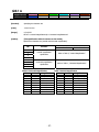
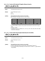
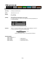
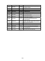
Commands for Non-volatile Memory
Command
GS ( C
GS ( L
GS 8 L
GS g 0
GS g 2
FS p
FS q
Function
Editing user NV memory
MODE
S
GS P
Page
112
Specifying graphics data
S
118
Initializing maintenance counter
Sending maintenance counter
Printing the download NV bit images
Defining the download NV bit image
S
S
S
S
126
127
128
130
Kanji Control Commands
Command
FS !
FS &
FS FS .
FS 2
FS C
FS S
FS W
FS ( A
Function
Collectively setting Kanji print mode
Setting Kanji mode
Setting/Canceling Kanji underline
Canceling Kanji mode
Defining external character
Selecting Kanji code system
Setting Kanji space amount
Setting/Canceling four times enlargement of Kanji
Setting font attribute of Kanji
MODE
S・P
S・P
S・P
S・P
S・P
S・P
S・P
S・P
S・P
GS P
MODE
S・P
S・P
S・P
S・P
S・P
S・P
S・P
S・P
S・P
GS P
Page
143
143
144
145
146
147
148
149
150
MODE
S
S
S
S
S
GS P
Page
152
153
200
204
207
MODE
S・P
GS P
Page
208
○
Page
132
133
134
135
136
138
140
141
142
Black Mark Control Commands
Command
GS FF
GS <
GS A
GS C 0
GS C 1
GS C 2
GS C ;
GS c
GS l
Function
Printing and ejecting Black mark paper
Initializing the printer mechanism
Correcting the leader position of Black mark paper
Setting the numbering print mode
Setting the numbering counter mode (A)
Setting the numbering counter
Setting the numbering counter mode (B)
Print the counter
Setting the Black mark length
Printer Function Setting Commands
Command
GS ( D
GS ( E
GS ( K
GS ( M
GS ( N
Function
Enabling or disabling real-time command
Printer function setting command
Selecting print control method
Customizing the printer
Designating font attribute
2-dimensional Code Commands
Command
GS ( k
Function
Setting and printing 2-dimensional code
- 18 -
Other Commands
Command
DLE ENQ
DLE DC4
ESC =
ESC @
ESC L
ESC S
ESC p
GS ( A
GS I
GS P
ESC RS
Function
Real-time request to printer
Outputting specified pulse in real-time/Buffer clear
Data input control
Initializing the printer
Selecting PAGE MODE
Selecting STANDARD MODE
Generating the specified pulses
Execution of test printing
Sending the printer ID
Specifying the basic calculation pitch
Sound buzzer
In the Mode column: S = STANDARD MODE, P = PAGE MODE
O = shows the command affected by GS P.
- 19 -
MODE
S・P
S・P
S・P
S・P
S
P
S・P
S
S・P
S・P
S・P
GS P
Page
219
220/221
222
223
224
225
226
227
228
235
236
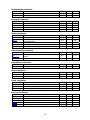
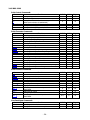
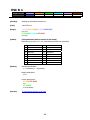
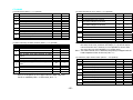
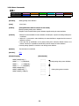
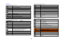
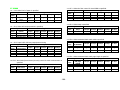
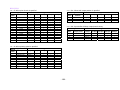
2.1.4 CT-S4000
Print Contorl Commands
Command
LF
CR
FF
ESC FF
ESC J
ESC d
Function
Printing and paper feed
Back to printing
(1)Printing in PAGE MODE and returning to STANDARD
MODE (at the selection of PAGE MODE)
(2)Printing of Black mark and paper feeding to the top of
the print position (with Black mark paper selected)
Printing data in PAGE MODE
Printing and feeding paper in minimum pitch
Printing and feeding the paper by “n” lines
MODE
S・P
S・P
GS P
P
P
S・P
S・P
Page
31
32
33
○
34
35
36
Print Character Commands
Command
CAN
ESC SP
ESC !
ESC %
ESC &
ESC ESC ?
ESC E
ESC G
ESC M
ESC R
ESC V
ESC t
ESC {
ESC ~ J
DC3
GS !
GS B
GS b
Function
Canceling print data in PAGE MODE
Setting the right spacing of the character
Collectively specifying the printing mode
Specifying/Canceling download character set
Defining the download characters
Specifying/canceling underline
Deleting download characters
Specifying/canceling emphasis printing
Specifying/canceling double strike printing
Selection of character fonts
Selecting the international character set
Specifying/canceling 90°-right-turned characters
Selecting the character code table
Specifying/canceling the inverted characters
Specifies/cancels printing in red (black-based paper)
Specifies/cancels printing in red (black-based paper)
Specifying the character size
Specifying/canceling the black/white inverted printing
Specifying/canceling the smoothing
MODE
P
S・P
S・P
S・P
S・P
S・P
S・P
S・P
S・P
S・P
S・P
S
S・P
S
S・P
S
S・P
S・P
S・P
GS P
MODE
S・P
S・P
S・P
P
P
S・P
S
GS P
P
○
69
S
S・P
○
○
70
71
S・P
○
73
○
Page
37
38
39
41
42
44
45
46
47
48
49
50
51
52
54
56
57
59
60
Print Position Commands
Command
HT
ESC $
ESC D
ESC T
ESC W
ESC \
ESC a
GS $
GS L
GS W
GS \
Function
Horizontal tab
Specifying the absolute positions
Setting horizontal tab position
Selecting the character printing direction in PAGE MODE
Defining the print area in PAGE MODE
Specifying the relative position
Aligning the characters
Specifying the absolute vertical position of characters in
PAGE MODE
Setting the left margin
Setting the print area width
Specifying the relative vertical position of a character in
PAGE MODE
- 20 -
○
○
○
Page
61
62
63
64
65
67
68
Line Feed Span Commands
Command
ESC 2
ESC 3
Function
Specifying initial line feed rate
Setting line feed rate of minimum pitch
MODE
S・P
S・P
GS P
MODE
S・P
S・P
S・P
S
GS P
Page
76
77
78
79
MODE
S・P
GS P
Page
81
○
Page
74
75
Bit Image Commands
Command
ESC *
GS *
GS /
GS v 0
Function
Specifying the bit image mode
Defining the download bit image
Printing the downloaded bit image
Printing of raster bit image
Status Commands
Command
DLE EOT
ESC u
ESC v
GS a
GS r
Function
Sending status in real-time
Transmitting the status of peripheral equipment
(Serial Mode Only)
Sending Printer status
Enabling/disabling ASB (Automatic Status Back)
Sending status
S・P
88
S・P
S・P
S・P
89
90
93
Paper Detecting Commands
Command
ESC c 3
ESC c 4
Function
Selecting the Paper Sensor valid for Paper-end signal
output
Selecting the Paper Near-end Sensor valid for print stop
MODE
GS P
Page
S・P
95
S・P
96
Panel Switch Commands
Command
ESC c 5
Function
Enabling/disabling the panel switches
MODE
S・P
GS P
Page
97
MODE
S・P
S・P
GS P
Page
98
99
MODE
S・P
S・P
S・P
GS P
Page
100
101
102
MODE
S・P
S・P
S・P
S・P
S・P
GS P
Macro Commands
Command
GS :
GS ^
Function
Starting/ending macro definition
Executing the macro
Cutter Commands
Command
ESC i
ESC m
GS V
Function
Full cut
Partial cut
Cutting the paper
○
Bar Code Commands
Command
GS H
GS f
GS h
GS k
GS w
Function
Selecting of printing position of HRI characters
Selecting the font of HRI characters
Specifying the height of the bar code
Printing the bar code
Specifying the horizontal size (magnification) of bar code
- 21 -
Page
103
104
105
106
111
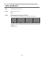
Commands for Non-volatile Memory
Command
GS ( C
GS ( L
GS 8 L
GS g 0
GS g 2
FS p
FS q
Function
Editing user NV memory
MODE
S
GS P
Page
112
Specifying graphics data
S
118
Initializing maintenance counter
Sending maintenance counter
Printing the download NV bit images
Defining the download NV bit image
S
S
S
S
126
127
128
130
Kanji Control Commands
Command
FS !
FS &
FS FS .
FS 2
FS C
FS S
FS W
FS ( A
Function
Collectively setting Kanji print mode
Setting Kanji mode
Setting/Canceling Kanji underline
Canceling Kanji mode
Defining external character
Selecting Kanji code system
Setting Kanji space amount
Setting/Canceling four times enlargement of Kanji
Setting font attribute of Kanji
MODE
S・P
S・P
S・P
S・P
S・P
S・P
S・P
S・P
S・P
GS P
MODE
S・P
S・P
S・P
S・P
S・P
S・P
S・P
S・P
S・P
S・P
GS P
Page
143
143
144
145
146
147
148
149
150
151
MODE
S
S
S
S
S
GS P
Page
152
153
200
204
207
MODE
S・P
GS P
Page
208
○
Page
132
133
134
135
136
138
140
141
142
Black Mark Control Commands
Command
GS FF
GS <
GS A
GS C 0
GS C 1
GS C 2
GS C ;
GS c
GS l
GS p
Function
Printing and ejecting Black mark paper
Initializing the printer mechanism
Correcting the leader position of Black mark paper
Setting the numbering print mode
Setting the numbering counter mode (A)
Setting the numbering counter
Setting the numbering counter mode (B)
Print the counter
Setting the Black mark length
Changing the paper type
Printer Function Setting Commands
Command
GS ( D
GS ( E
GS ( K
GS ( M
GS ( N
Function
Enabling or disabling real-time command
Printer function setting command
Selecting print control method
Customizing the printer
Designating font attribute
2-dimensional Code Commands
Command
GS ( k
Function
Setting and printing 2-dimensional code
- 22 -
Other Commands
Command
DLE ENQ
DLE DC4
ESC =
ESC @
ESC L
ESC S
ESC p
GS ( A
GS I
GS P
ESC RS
Function
Real-time request to printer
Outputting specified pulse in real-time/Buffer clear
Data input control
Initializing the printer
Selecting PAGE MODE
Selecting STANDARD MODE
Generating the specified pulses
Execution of test printing
Sending the printer ID
Specifying the basic calculation pitch
Sound buzzer
In the Mode column: S = STANDARD MODE, P = PAGE MODE
O = shows the command affected by GS P.
- 23 -
MODE
S・P
S・P
S・P
S・P
S
P
S・P
S
S・P
S・P
S・P
GS P
Page
219
220/221
222
223
224
225
226
227
228
235
236
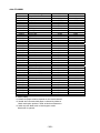
2.1.5 BD2-2220
Print Contorl Commands
Command
LF
CR
FF
ESC FF
ESC J
ESC d
Function
Printing and paper feed
Back to printing
Printing in PAGE MODE and returning to STANDARD
MODE (at the selection of PAGE MODE)
Printing data in PAGE MODE
Printing and feeding paper in minimum pitch
Printing and feeding the paper by “n” lines
MODE
S・P
S・P
GS P
Page
31
32
P
33
P
S・P
S・P
34
35
36
○
Print Character Commands
Command
CAN
ESC SP
ESC !
ESC %
ESC &
ESC ESC ?
ESC E
ESC G
ESC M
ESC R
ESC V
ESC t
ESC {
GS !
GS B
GS b
Function
Canceling print data in PAGE MODE
Setting the right spacing of the character
Collectively specifying the printing mode
Specifying/Canceling download character set
Defining the download characters
Specifying/canceling underline
Deleting download characters
Specifying/canceling emphasis printing
Specifying/canceling double strike printing
Selection of character fonts
Selecting the international character set
Specifying/canceling 90°-right-turned characters
Selecting the character code table
Specifying/canceling the inverted characters
Specifying the character size
Specifying/canceling the black/white inverted printing
Specifying/canceling the smoothing
MODE
P
S・P
S・P
S・P
S・P
S・P
S・P
S・P
S・P
S・P
S・P
S
S・P
S
S・P
S・P
S・P
GS P
MODE
S・P
S・P
S・P
P
P
S・P
S
GS P
P
○
69
S
S・P
○
○
70
71
S・P
○
73
MODE
S・P
S・P
GS P
Page
74
75
○
Page
37
38
39
41
42
44
45
46
47
48
49
50
51
52
57
59
60
Print Position Commands
Command
HT
ESC $
ESC D
ESC T
ESC W
ESC \
ESC a
GS $
GS L
GS W
GS \
Function
Horizontal tab
Specifying the absolute positions
Setting horizontal tab position
Selecting the character printing direction in PAGE MODE
Defining the print area in PAGE MODE
Specifying the relative position
Aligning the characters
Specifying the absolute vertical position of characters in
PAGE MODE
Setting the left margin
Setting the print area width
Specifying the relative vertical position of a character in
PAGE MODE
○
○
○
Page
61
62
63
64
65
67
68
Line Feed Span Commands
Command
ESC 2
ESC 3
Function
Specifying initial line feed rate
Setting line feed rate of minimum pitch
- 24 -
○
Bit Image Commands
Command
ESC *
GS *
GS /
GS v 0
Function
Specifying the bit image mode
Defining the download bit image
Printing the downloaded bit image
Printing of raster bit image
MODE
S・P
S・P
S・P
S
GS P
Page
76
77
78
79
MODE
S・P
S・P
S・P
GS P
Page
81
90
93
MODE
GS P
Page
Status Commands
Command
DLE EOT
GS a
GS r
Function
Sending status in real-time
Enabling/disabling ASB (Automatic Status Back)
Sending status
Paper Detecting Commands
Command
ESC c 3
ESC c 4
Function
Selecting the Paper Sensor valid for Paper-end signal
output
Selecting the Paper Near-end Sensor valid for print stop
S・P
95
S・P
96
Panel Switch Commands
Command
ESC c 5
Function
Enabling/disabling the panel switches
MODE
S・P
GS P
Page
97
MODE
S・P
S・P
GS P
Page
98
99
MODE
S・P
S・P
S・P
GS P
Page
100
101
102
MODE
S・P
S・P
S・P
S・P
S・P
GS P
Page
103
104
105
106
111
MODE
S
S
GS P
Page
128
130
Macro Commands
Command
GS :
GS ^
Function
Starting/ending macro definition
Executing the macro
Cutter Commands
Command
ESC i
ESC m
GS V
Function
Full cut
Partial cut
Cutting the paper
○
Bar Code Commands
Command
GS H
GS f
GS h
GS k
GS w
Function
Selecting of printing position of HRI characters
Selecting the font of HRI characters
Specifying the height of the bar code
Printing the bar code
Specifying the horizontal size (magnification) of bar code
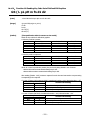
Commands for Non-volatile Memory
Command
FS p
FS q
Function
Printing the download NV bit images
Defining the download NV bit image
- 25 -
Kanji Control Commands
Command
FS !
FS &
FS FS .
FS 2
FS C
FS S
FS W
FS ( A
Function
Collectively setting Kanji print mode
Setting Kanji mode
Setting/Canceling Kanji underline
Canceling Kanji mode
Defining external character
Selecting Kanji code system
Setting Kanji space amount
Setting/Canceling four times enlargement of Kanji
Setting font attribute of Kanji
MODE
S・P
S・P
S・P
S・P
S・P
S・P
S・P
S・P
S・P
GS P
MODE
S
S
S
GS P
Page
153
200
204
MODE
S・P
S・P
S・P
S・P
S
P
S
S・P
S・P
GS P
Page
219
221
222
223
224
225
227
228
235
○
Page
132
133
134
135
136
138
140
141
142
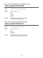
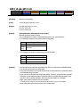
Printer Function Setting Commands
Command
GS ( E
GS ( K
GS ( M
Function
Printer function setting command
Selecting print control method
Customizing the printer
Other Commands
Command
DLE ENQ
DLE DC4
ESC =
ESC @
ESC L
ESC S
GS ( A
GS I
GS P
Function
Real-time request to printer
Buffer clear
Data input control
Initializing the printer
Selecting PAGE MODE
Selecting STANDARD MODE
Execution of test printing
Sending the printer ID
Specifying the basic calculation pitch
In the Mode column: S = STANDARD MODE, P = PAGE MODE
O = shows the command affected by GS P.
- 26 -
2.1.6 PMU2XXX
Print Contorl Commands
Command
LF
CR
FF
ESC FF
ESC J
ESC d
Function
Printing and paper feed
Back to printing
(1)Printing in PAGE MODE and returning to STANDARD
MODE (at the selection of PAGE MODE)
(2)Printing of Black mark and paper feeding to the top of
the print position (with Black mark paper selected)
Printing data in PAGE MODE
Printing and feeding paper in minimum pitch
Printing and feeding the paper by “n” lines
MODE
S・P
S・P
GS P
Page
31
32
P
33
P
S・P
S・P
34
35
36
○
Print Character Commands
Command
CAN
ESC SP
ESC !
ESC %
ESC &
ESC ESC ?
ESC E
ESC G
ESC M
ESC R
ESC V
ESC t
ESC {
GS !
GS B
GS b
Function
Canceling print data in PAGE MODE
Setting the right spacing of the character
Collectively specifying the printing mode
Specifying/Canceling download character set
Defining the download characters
Specifying/canceling underline
Deleting download characters
Specifying/canceling emphasis printing
Specifying/canceling double strike printing
Selection of character fonts
Selecting the international character set
Specifying/canceling 90°-right-turned characters
Selecting the character code table
Specifying/canceling the inverted characters
Specifying the character size
Specifying/canceling the black/white inverted printing
Specifying/canceling the smoothing
MODE
P
S・P
S・P
S・P
S・P
S・P
S・P
S・P
S・P
S・P
S・P
S
S・P
S
S・P
S・P
S・P
GS P
MODE
S・P
S・P
S・P
P
P
S・P
S
GS P
P
○
69
S
S・P
○
○
70
71
S・P
○
73
MODE
S・P
S・P
GS P
Page
74
75
○
Page
37
38
39
41
42
44
45
46
47
48
49
50
51
52
57
59
60
Print Position Commands
Command
HT
ESC $
ESC D
ESC T
ESC W
ESC \
ESC a
GS $
GS L
GS W
GS \
Function
Horizontal tab
Specifying the absolute positions
Setting horizontal tab position
Selecting the character printing direction in PAGE MODE
Defining the print area in PAGE MODE
Specifying the relative position
Aligning the characters
Specifying the absolute vertical position of characters in
PAGE MODE
Setting the left margin
Setting the print area width
Specifying the relative vertical position of a character in
PAGE MODE
○
○
○
Page
61
62
63
64
65
67
68
Line Feed Span Commands
Command
ESC 2
ESC 3
Function
Specifying initial line feed rate
Setting line feed rate of minimum pitch
- 27 -
○
Bit Image Commands
Command
ESC *
GS *
GS /
GS v 0
Function
Specifying the bit image mode
Defining the download bit image
Printing the downloaded bit image
Printing of raster bit image
MODE
S・P
S・P
S・P
S
GS P
Page
76
77
78
79
MODE
S・P
S・P
S・P
GS P
Page
81
90
93
MODE
GS P
Page
Status Commands
Command
DLE EOT
GS a
GS r
Function
Sending status in real-time
Enabling/disabling ASB (Automatic Status Back)
Sending status
Paper Detecting Commands
Command
ESC c 3
ESC c 4
Function
Selecting the Paper Sensor valid for Paper-end signal
output
Selecting the Paper Near-end Sensor valid for print stop
S・P
95
S・P
96
Panel Switch Commands
Command
ESC c 5
Function
Enabling/disabling the panel switches
MODE
S・P
GS P
Page
97
MODE
S・P
S・P
GS P
Page
98
99
MODE
S・P
S・P
S・P
GS P
Page
100
101
102
MODE
S・P
S・P
S・P
S・P
S・P
GS P
Page
103
104
105
106
111
MODE
S
S
GS P
Page
128
130
Macro Commands
Command
GS :
GS ^
Function
Starting/ending macro definition
Executing the macro
Cutter Commands
Command
ESC i
ESC m
GS V
Function
Full cut
Partial cut
Cutting the paper
○
Bar Code Commands
Command
GS H
GS f
GS h
GS k
GS w
Function
Selecting of printing position of HRI characters
Selecting the font of HRI characters
Specifying the height of the bar code
Printing the bar code
Specifying the horizontal size (magnification) of bar code
Commands for Non-volatile Memory
Command
FS p
FS q
Function
Printing the download NV bit images
Defining the download NV bit image
- 28 -
Kanji Control Commands
Command
FS !
FS &
FS FS .
FS 2
FS C
FS S
FS W
FS ( A
Function
Collectively setting Kanji print mode
Setting Kanji mode
Setting/Canceling Kanji underline
Canceling Kanji mode
Defining external character
Selecting Kanji code system
Setting Kanji space amount
Setting/Canceling four times enlargement of Kanji
Setting font attribute of Kanji
MODE
S・P
S・P
S・P
S・P
S・P
S・P
S・P
S・P
S・P
GS P
MODE
S・P
GS P
Page
143
MODE
S
S
S
GS P
Page
153
200
204
MODE
S・P
S・P
S・P
S・P
S
P
S
S・P
S・P
GS P
Page
219
221
222
223
224
225
227
228
235
○
Page
132
133
134
135
136
138
140
141
142
Black Mark Control Commands
Command
GS FF
Function
Printing and ejecting Black mark paper
Printer Function Setting Commands
Command
GS ( E
GS ( K
GS ( M
Function
Printer function setting command
Selecting print control method
Customizing the printer
Other Commands
Command
DLE ENQ
DLE DC4
ESC =
ESC @
ESC L
ESC S
GS ( A
GS I
GS P
Function
Real-time request to printer
Buffer clear
Data input control
Initializing the printer
Selecting PAGE MODE
Selecting STANDARD MODE
Execution of test printing
Sending the printer ID
Specifying the basic calculation pitch
In the Mode column: S = STANDARD MODE, P = PAGE MODE
O = shows the command affected by GS P.
- 29 -
2.2 Command Details
2.2.1 Description of Items
XXXX
support model
[Function]
[Code]
[Range]
[Outline]
The name of a command.
The string of codes comprising the command is represented by < >H for hexadecimal numbers, < >B
for binary numbers, and < > for decimal numbers, [ ] k denotes the number of repetition of “k” times.
Indicates the values (setting range) of arguments of the command.
Note: If values outside the defined domain specified with control codes are used, malfunctions
could possibly occur, so be sure to use the values within the defined domain.
*The defined domain may differ depending on the model or printer setting.
[The specification which is common to the model]
Indicates command functions common to relevant models.
[The specification which depend on the model]
Indicates the command function dependent on the model.
[Caution]
Describes important points and cautionary notes, as required.
[Default]
Initial values for the command if it has arguments.
[See Also]
Describes commands related to the command when it is used.
[Sample Program]
Describes examples of coding on Quick-Basic.
* Examples are only for reference. They may vary depending on language and version. For details, please refer
to a manual in your language.
[Print Results]
Describes the print results obtained by executing the above programs. However, the print results shown are
different in scale from actual print results
- 30 -
2.2.2 Print Control Commands
LF
support model
CT-S280
PMU2XXX
CT-S300
CT-S2000
CT-S4000
BD2-2220
CT-S310
[Function]
Printing and paper feed
[Code]
<0A>H
[Outline]
[The specification which is common to the model]
Prints data inside the print buffer and feeds paper based on the line feed amount having been set.
[Caution]
After this command is executed, the beginning of the line is taken as the start position for the next
point.
[See Also]
ESC 2、ESC 3
[Sample Program]
[Print Results]
AAA
BBB
LPRINT "AAA"; CHR$(&HA);
LPRINT "BBB"; CHR$(&HA); CHR$(&HA);
LPRINT "CCC"; CHR$(&HA);
Print and line feed
Print and line feed
Line feed only
CCC
- 31 -
Print and line feed
CR
support model
CT-S280
PMU2XXX
CT-S300
CT-S2000
CT-S4000
[Function]
Back to printing
[Code]
<0D>H
[Outline]
[The specification which is common to the model]
(1) When memory switch 1-5 is OFF:
This command is ignored.
(2) When memory switch 1-5 is ON:
The same operation as LF is executed.
[See Also]
LF
[Sample Program]
LPRINT "AAA"; CHR$(&HD);
LPRINT "BBB"; CHR$(&HD);
LPRINT CHR$(&HD);
LPRINT "CCC"; CHR$(&HD);
BD2-2220
[Print Results]
In case of (2)
AAA
BBB
Print and line feed
Print and line feed
Line feed only
CCC
- 32 -
Print and line feed
CT-S310
FF (At selection of PAGE MODE)
support model
CT-S280
PMU2XXX
CT-S300
CT-S2000
CT-S4000
BD2-2220
CT-S310
[Function]
Printing in PAGE MODE and returning to STANDARD MODE (at the selection of PAGE MODE)
[Code]
<0C>H
[Outline]
[The specification which is common to the model]
Executes a batch printout of the data mapped in the entire print area, and then returns to
STANDARD MODE.
[Caution]
• All mapped data is erased after printout.
• The print area set up by ESC W is initialized.
• This command does not execute a paper cut.
• After this command is executed, the beginning of the line is taken as the start position for the next
print.
• This command is only effective when the PAGE MODE is selected.
CT-S4000
• When selecting BM paper or label paper to specify the PAGE MODE, data extended to all
printing area is printed in batch. After returning to the STANDARD MODE, setting the
start position of next label is carried out.
[See Also]
Appendix 5.1.4 “Example of Using PAGE MODE”
ESC FF、ESC L、ESC S
FF (valid only for Black mark specification)
support model
CT-S280
PMU2XXX
CT-S300
CT-S2000
CT-S4000
BD2-2220
CT-S310
[Function]
At selection of Black mark paper (valid only for Black mark specification)
[Outline]
[The specification which is common to the model]
This command prints the data in the printer buffer and searches for the head of the next Black mark
(Black mark position)
[Caution]
• This command does not execute a paper cut.
• After this command is executed, the beginning of the line is taken as the start position for the next
print.
• Valid only for label- or BM-supported model.
(Please confirm specifications for the details.)
[See Also]
GS FF
- 33 -
ESC FF
support model
CT-S280
PMU2XXX
CT-S300
CT-S2000
CT-S4000
BD2-2220
CT-S310
[Function]
Printing data in PAGE MODE
[Code]
<1B>H<0C>H
[Outline]
[The specification which is common to the model]
Executes a batch printout of the data mapped in the entire print area in PAGE MODE.
[Caution]
• This command is only effective when PAGE MODE is selected.
• Mapped data, as well as the ESC T and ESC W settings, and the character mapping position are
held even after printing.
[See Also]
Appendix 5.1 “Explanation on PAGE MODE”
FF、ESC L、ESC S
- 34 -
ESC J n
support model
CT-S280
PMU2XXX
CT-S300
CT-S2000
CT-S4000
BD2-2220
CT-S310
[Function]
Printing and feeding paper in minimum pitch
[Code]
<1B>H<4A>H<n>
[Range]
0≦n≦255
[Outline]
[The specification which is common to the model]
Prints the data held in the print buffer and feeds paper by [n×basic calculation pitch] inches.
[Caution]
• After this command is executed, the beginning of the line is taken as the start position for the next
print.
• The line feed width can be set separately for the STANDARD and PAGE MODES.
• This command does not affect the line feed width defined by ESC 2 or ESC 3.
• The basic calculation pitch is set by GS P.
• Fractions resulting from calculation are corrected with the minimum pitch of the mechanism, and
the remainder is omitted.
• In STANDARD MODE, this command uses the vertical (paper feed direction) basic calculation pitch
(y).
• In PAGE MODE, this command acts differently depending on the start point:
(1) If the start point specified by ESC T is top left or bottom right, the command uses the vertical
(Paper feed direction) basic calculation pitch (y).
(2) If the start point specified by ESC T is top right or bottom left, the command uses the
horizontal (Perpendicular to the paper feed direction) basic calculation pitch (x).
• The maximum settable line feed width is 1016 mm (40 inches). A setting greater than this
maximum is trimmed to the maximum.
[Default]
The initial value is not defined.
[Sample Program]
Refer to Sample Program and Print Results for ESC 2.
- 35 -
ESC d n
support model
CT-S280
PMU2XXX
CT-S300
CT-S2000
CT-S4000
BD2-2220
CT-S310
[Function]
Printing and feeding the paper by “n” lines
[Code]
<1B>H<64>H<n>
[Range]
0≦n≦255
[Outline]
[The specification which is common to the model]
Prints data in the print buffer and feeds paper by “n” lines. Specified lines do not remain.
[Caution]
• After this command is executed, the beginning of the line is taken as the start position for the next
print.
• If [n×line feed width] exceeds approximately 1016 mm, this command feeds paper by
approximately 1016 mm (40 inches).
[Default]
The initial value is not defined.
[Sample Program]
[Print Results]
LPRINT "AAAAA";
LPRINT CHR$(&H1B);"d";CHR$(2);
LPRINT "AAAAA";CHR$(&HA);
AAAAA
AAAAA
- 36 -
2/6-inch line feed
2.2.3 Print Character Commands
CAN
support model
CT-S280
PMU2XXX
CT-S300
CT-S2000
CT-S4000
BD2-2220
CT-S310
[Function]
Canceling print data in PAGE MODE
[Code]
<18>H
[Outline]
[The specification which is common to the model]
Erases all data contained in the currently effective print area in PAGE MODE.
[Caution]
• This command is only effective when PAGE MODE is selected.
• If the previously established print area overlaps the currently effective print area, the overlapped
data in the previously established area will be erased.
[See Also]
Appendix 5.1 “Explanation on PAGE MODE”
ESC L、ESC W
- 37 -
ESC SP n
support model
[Function]
[Code]
CT-S280
PMU2XXX
CT-S300
CT-S2000
CT-S4000
BD2-2220
CT-S310
Setting the right spacing of the character
<1B>H<20>H<n>
[Range]
0≦n≦255
[Outline]
[The specification which is common to the model]
Sets the right spacing of character to [n×basic calculation pitch] inches.
[Caution]
• If the horizontal magnification of character is 2 or more, the right spacing increases with the
magnification.
• Does not affect Kanji.
• The right spacing can be set separately for the STANDARD and PAGE MODES.
• The basic calculation pitch is set by GS P. Once defined, the right spacing is not changed if the
basic calculation pitch is changed by GS P.
• Fractions resulting from calculation are corrected with the minimum pitch of the mechanism, and
the remainder is omitted.
• In STANDARD MODE, this command uses the horizontal basic calculation pitch (x).
• In PAGE MODE, the basic calculation pitch used by this command depends on the start point:
(1) If the start point specified by ESC T is top left or bottom right, the command uses the
horizontal basic calculation pitch (x).
(2) If the start point specified by ESC T is top right or bottom left, the command uses the vertical
basic calculation pitch (y).
• The maximum right spacing is capable of approximately 31.906 mm (255/203 inches). A setting
greater than this maximum is trimmed to the maximum.
[Default]
n=0
[See Also]
GS P
[Sample Program]
LPRINT CHR$(&H1B);" "; CHR$(0);
LPRINT "AAAAA"; CHR$(&HA);
LPRINT CHR$(&H1B);" "; CHR$(1);
LPRINT "AAAAA"; CHR$(&HA);
LPRINT CHR$(&H1B);" "; CHR$(12);
LPRINT "AAAAA"; CHR$(&HA);
[Print Results]
AAAAA
AAAAA
A A A A A
- 38 -
0-dot space
1-dot space
12-dots space
ESC ! n
CT-S280
PMU2XXX
support model
CT-S300
CT-S2000
CT-S4000
[Function]
Collectively specifying the printing mode
[Code]
<1B>H<21>H<n>
[Range]
0≦n≦255
[Outline]
[The specification which is common to the model]
Printing mode is assigned.
BD2-2220
[The specification which depend on the model]
CT-S300/CT-S310
Bit
Function
0
1
2
3
4
5
6
7
Character Font
Undefined
Undefined
Emphasis
Double height
Double width
Undefined
Underline
Value
0
1
Font A (12 x 24)
—
—
Canceled
Canceled
Canceled
—
Canceled
Font B (9 x 17)
—
—
Specified
Specified
Specified
—
Specified
CT-S280/CT-S2000/CT-S4000/BD2-2220/PMU2XXX
Bit
Function
0
1
2
3
4
5
6
7
Character Font
Undefined
Undefined
Emphasis
Double height
Double width
Undefined
Underline
Value
0
1
Font A (12 x 24)
—
—
Canceled
Canceled
Canceled
—
Canceled
Font B (9 x 24)
—
—
Specified
Specified
Specified
—
Specified
- 39 -
CT-S310
[Caution]
• With double height and double width being specified simultaneously, quadruple characters are
created.
• An underline is attached to the full character width, which, however, is not attached to the part
having been skipped by the horizontal tab (HT). Neither is it attached to 90°-right-turned
characters.
• The underline width is as specified by the ESC – command. (The default setting is 1 dot width.)
• Setting by this command is invalid for Kanji except setting and canceling of enhanced printing.
• In case characters with different vertical magnification ratios coexist on the same line, they are
printed on the same base line.
• ESC E, ESC M, ESC –, and GS ! can individually set or cancel the mode but the command
processed last is valid.
• Setting or canceling of enhanced 3rd bit is valid for alphanumeric and kana and kanji. Other print
mode is valid only for alphanumeric and kana characters.
[Default]
n=0
[See Also]
ESC E、ESC -、GS !
[Sample Program]
[Print Results]
LPRINT CHR$(&H1B);"!"; CHR$(&H00);"H";
LPRINT CHR$(&H1B);"!"; CHR$(&H01);"H";
LPRINT CHR$(&H1B);"!"; CHR$(&H08);"H";
LPRINT CHR$(&H1B);"!"; CHR$(&H10);"H";
LPRINT CHR$(&H1B);"!"; CHR$(&H20);"H";
LPRINT CHR$(&H1B);"!"; CHR$(&H80);"H";
LPRINT CHR$(&H1B);"!"; CHR$(&HB9);"H";
LPRINT CHR$(&HA);
Font B + Emphasis
+ Quadruple + Underline
Font A + Underline
Font A + Double width
Font A + Double height
Font A + Emphasis
Font B
Font A
- 40 -
ESC % n
CT-S280
PMU2XXX
support model
CT-S300
CT-S2000
CT-S4000
[Function]
Specifying/canceling download character set
[Code]
<1B>H<25>H<n>
[Range]
0≦n≦255
[Outline]
[The specification which is common to the model]
Specifying/canceling download characters.
• “n” is valid only for the lowest bit (n0).
• Control by the lowest bit (n0) is shown as follows:
n0
0
1
[Default]
n=0
[See Also]
ESC &
Function
Canceling download character set
Specifying download character set
[Sample Program]
GOSUB SETCHR
LPRINT CHR$(&H1B);"%";CHR$(0);
LPRINT "@A";CHR$(&HA);
LPRINT CHR$(&H1B);"%";CHR$(1);
LPRINT "@A";CHR$(&HA);
END
SETCHR:
LPRINT CHR$(&H1B);"&";
LPRINT CHR$(3);"@";"A";
FOR J=1 TO 2
READ REP
LPRINT CHR$(REP);
FOR I=1 TO REP*3
READ D
LPRINT CHR$(D);
NEXT I
NEXT J
RETURN
DATA 6
DATA &HFF,&H80,&H00
DATA &H80,&H80,&H00
DATA &H80,&H80,&H00
DATA &H80,&H80,&H00
DATA &HFF,&HFF,&HFF
DATA &HFF,&HFF,&HFF
DACT-S2000
DATA &HFF,&HFF,&HFF
DATA &H80,&H07,&HF9
DATA &H80,&HFF,&HF9
DATA &H87,&HFE,&H01
DATA &H9F,&H06,&H01
DATA &HF8,&H06,&H01
DATA &HF8,&H06,&H01
DATA &H9F,&H06,&H01
DATA &H87,&HFE,&H01
DATA &H80,&HFF,&HF9
DATA &H80,&H07,&HF9
DATA &HFF,&HFF,&HFF
[Print Results]
@ A
A
Internal character set
Download character
- 41 -
BD2-2220
CT-S310
ESC & s n m [ a [p] s x a ] m-n+1
support model
CT-S280
PMU2XXX
CT-S300
CT-S2000
CT-S4000
BD2-2220
CT-S310
[Function]
Defining the download characters
[Code]
<1B>H<26>H<s>H<n>H<m>H[<a>H<p1>H<p2>・・・<ps×a>]m-n+1
[Range]
s=3(Font A, B) s=2(FontC)
32≦n≦m≦127
0≦a≦12(Font A)
0≦a≦9 (Font B)
0≦a≦8 (Font C)
0≦p1・・ps×a≦255
[Outline]
[The specification which is common to the model]
Defines the font of download characters of alphanumeric characters.
• “s” indicates the number of bytes in vertical direction.
• “n” indicates the start character code and “m” the end character code. To define only one
character, set n = m.
• Character codes definable includes 95 ASCII codes in total in the range of <20>H to <7E>H.
• “a” indicates the number of dots to be defined in horizontal direction.
• “p” is the data to be defined, which indicate a pattern equal to “a” dots in horizontal direction from
the left end. The rest of the pattern on the right side is filled with space.
• The number of data to be defined is “s x a”.
• Download characters thus defined remain valid until redefinition, execution of ESC @, GS *, FS q,
GS (A, deletion by ESC ?, or power OFF is performed.
[Caution]
CT-S280/CT-S300/BD2-2220/CT-S310/PMU2XXX
• Running this command clears the definition of the download bit image.
CT-S2000/CT-S4000
• Running this command doesn't clear the definition of the download bit image.
[Default]
Same as the internal character set.
[See Also]
ESC %、ESC ?
- 42 -
[Example]
12dot
24dot
p1
p4
p34
p2
p5
p35
p3
p6
p36
Font A
MSB
LSB
Create each data bit by setting “1” for a printed dot and “0” for an unprinted dot.
[Sample Program]
Refer to Sample Program and Print Results for ESC %.
- 43 -
ESC - n
support model
CT-S280
PMU2XXX
CT-S300
CT-S2000
CT-S4000
[Function]
Specifying /canceling underline
[Code]
<1B>H<2D>H<n>
[Range]
0≦n≦2、48≦n≦50
[Outline]
[The specification which is common to the model]
Specifying /canceling an underline.
n
0,48
1,49
2,50
BD2-2220
CT-S310
Function
Canceling underline
Setting 1-dot width underline
Setting 2-dot width underline
[Caution]
• An underline is attached to the full character width. It is, however, not attached to the part having
been skipped by horizontal tab (HT) command.
• An underline is not attached to 90°-right-turned characters and white-on-black character.
• Underline can also be specified/canceled by ESC ! but the setting of command last processed is
valid.
• Specifying/canceling by this command is not valid for kanji.
• Underline width is constant in the specified thickness regardless of the character size.
[Default]
n=0
[See Also]
ESC !、FS -
[Sample Program]
LPRINT CHR$(&H1B);"-"; CHR$(0);
LPRINT "AAAAA";
LPRINT CHR$(&H1B);"-"; CHR$(1);
LPRINT "AAAAA"; CHR$(&HA);
[Print Results]
Underline canceled
AAAAAAAAAA
Underline specified
- 44 -
ESC ? n
support model
CT-S280
PMU2XXX
CT-S300
CT-S2000
CT-S4000
BD2-2220
CT-S310
[Function]
Deleting download characters
[Code]
<1B>H<3F>H<n>
[Range]
32≦n≦126
[Outline]
[The specification which is common to the model]
Deletes the downloaded characters of specified code.
[Caution]
• The character “n” indicates the character code used to delete the defined pattern. After the
deletion, characters are printed in the same pattern as the internal characters.
• This command deletes the code-defined pattern of the character font selected by ESC !.
• This command is ignored if the specified character code is undefined.
[See Also]
ESC &、ESC %
- 45 -
ESC E n
CT-S280
PMU2XXX
support model
CT-S300
CT-S2000
CT-S4000
[Function]
Specifying/canceling emphasis printing
[Code]
<1B>H<45>H<n>
[Range]
0≦n≦255
[Outline]
[The specification which is common to the model]
Specifying/canceling the emphasized characters.
• “n” is valid only for the lowest bit (n0).
• Control by the lowest bit (n0) is shown as follows:
n0
0
1
BD2-2220
CT-S310
Function
Canceling emphasis printing
Specifying emphasis printing
[Caution]
• Emphasis printing can also be specified/canceled by ESC ! but the setting of command last
processed is valid.
• Valid for all character types except HRI characters.
[Default]
n=0
[See Also]
ESC !
[Sample Program]
[Print Results]
LPRINT CHR$(&H1B);"E"; CHR$(0);
LPRINT "AAABBB"; CHR$(&HA);
LPRINT CHR$(&H1B);"E"; CHR$(1);
LPRINT "AAABBB"; CHR$(&HA);
AAABBB
AAABBB
- 46 -
Emphasis canceled
Emphasis specified
ESC G n
CT-S280
PMU2XXX
support model
CT-S300
CT-S2000
CT-S4000
[Function]
Specifying/canceling double strike printing
[Code]
<1B>H<47>H<n>
[Range]
0≦n≦255
[Outline]
[The specification which is common to the model]
Specifying /canceling the double strike printing.
• “n” is valid only for the lowest bit (n0).
• Control by the lowest bit (n0) is shown as follows:
n0
0
1
BD2-2220
CT-S310
Function
Canceling double strike printing
Specifying double strike printing
[Caution]
• With this printer, double-strike printing and emphasis printing provide completely the same
results.
• Valid for all character types except HRI characters.
[Default]
n=0
[See Also]
ESC E
[Sample Program]
LPRINT CHR$(&H1B);"G"; CHR$(0);
LPRINT "AAABBB"; CHR$(&HA);
LPRINT CHR$(&H1B);"G"; CHR$(1);
LPRINT "AAABBB"; CHR$(&HA);
[Print Results]
AAABBB
AAABBB
- 47 -
Double strike printing canceled
Double strike printing specified
ESC M n
CT-S280
PMU2XXX
support model
CT-S300
CT-S2000
CT-S4000
[Function]
Selection of character fonts
[Code]
<1B>H<4D>H<n>
[Range]
0≦n≦2、48≦n≦50
[Outline]
[The specification which is common to the model]
Selects character fonts.
BD2-2220
CT-S310
[The specification which depend on the model]
CT-S300/CT-S310
n
0,48
1,49
2,50
Function
Selection of font A (12 x 24)
Selection of font B (9 x 17)
Selection of font C (8 x 16)
CT-S280/CT-S2000/CT-S4000/BD2-2220/PMU2XXX
n
0,48
1,49
2,50
Function
Selection of font A (12 x 24)
Selection of font B (9 x 24)
Selection of font C (8 x 16)
[Caution]
• ESC ! can also select fonts, but the setting made by the command that has last been processed
becomes valid.
[Default]
n=0
[See Also]
ESC!
- 48 -
ESC R n
CT-S280
PMU2XXX
support model
CT-S300
CT-S2000
[Function]
Selecting the international character set
[Code]
<1B>H<52>H<n>
[Range]
CT-S4000
BD2-2220
CT-S280/CT-S300/BD2-2220/PMU2XXX
0≦n≦13
CT-S2000/CT-S4000/CT-S310
0≦n≦15
[Outline]
[The specification which is common to the model]
Depending on the value of “n”, one of the following character sets is specified;
n
0
1
2
3
4
5
6
7
[Default]
Character Set
U.S.A.
France
Germany
U.K.
Denmark I
Sweden
Italy
Spain I
n
8
9
10
11
12
13
14
15
Character Set
Japan
Norway
Denmark II
Spain II
Latin America
Korea
Croatia
China
standard specifications:
n = 0 (Overseas), n = 8 (Domestic)
Hangul specifications:
n=13
Chinese specifications:
CT-S300/CT-S310
n=0
CT-S2000
n=15(CT-S2000)
[See Also]
3.2 “International Character Code Table”
- 49 -
CT-S310
ESC V n
CT-S280
PMU2XXX
support model
CT-S300
CT-S2000
CT-S4000
[Function]
Specifying/canceling 90°-right-turned characters
[Code]
<1B>H<56>H<n>
[Range]
0≦n≦1、48≦n≦49
[Outline]
[The specification which is common to the model]
Specifying/canceling 90°-right-turned characters.
n
BD2-2220
Function
0,48
1,49
Canceling 90°-right-turned characters
Specifying 90°-right-turned characters
[Caution]
• No underlines are attached to 90°-right-turned characters.
• This command does not affect PAGE MODE but setting is maintained.
[Default]
n=0
[Sample Program]
LPRINT CHR$(&H1B);"V"; CHR$(0);
LPRINT "AAAAA";
LPRINT CHR$(&H1B);"V"; CHR$(1);
LPRINT "AAAAA"; CHR$(&HA);
[Print Results]
90° rotation canceled
90° rotation specified
- 50 -
CT-S310
ESC t n
support model
CT-S280
PMU2XXX
CT-S300
CT-S2000
[Function]
Selecting the character code table
[Code]
<1B>H<74>H<n>
[Range]
0≦n≦9、16≦n≦19、n=26、40、255
[Outline]
[Default]
CT-S4000
BD2-2220
[The specification which is common to the model]
Selecting the character code table.
The character code table is selected based on the value of “n”.
n
Character Code Table
n
Character Code Table
0
1
2
3
4
5
6,18
Codepage PC437
Katakana
Codepage PC850
Codepage PC860
Codepage PC863
Codepage PC865
Codepage PC852
7,17
8
9,16
19
26
40
255
Codepage PC866
Codepage PC857
Windows code
Codepage PC858
Thai code 18
Codepage PC864
Space page (For user setting)
n=0 (Overseas)
n=1 (Domestic)
[Sample Program]
[Print Results]
LPRINT CHR$(&H1B);"t"; CHR$(0);
LPRINT "n=0 ";
FOR C=&HB1 TO &HB5
LPRINT CHR$(C);
NEXT C
LPRINT CHR$(&HA);
LPRINT CHR$(&H1B);"t"; CHR$(1);
LPRINT "n=1 ";
FOR C=&HB1 TO &HB5
LPRINT CHR$(C);
NEXT C
LPRINT CHR$(&HA);
n=0
n=1
- 51 -
アイウエオ
CT-S310
ESC { n
CT-S280
PMU2XXX
support model
CT-S300
CT-S2000
CT-S4000
[Function]
Specifying/canceling the inverted characters
[Code]
<1B>H<7B>H<n>
[Range]
0≦n≦255
[Outline]
[The specification which is common to the model]
• “n” is valid only for the lowest bit (n0).
• Rotate data in the line by 180 degrees and print it.
• Control by the lowest bit (n0) is shown as follows:
n0
0
1
BD2-2220
Function
Canceling inverted characters.
Specifying inverted characters.
[Caution]
• This command is valid only when it is specified at the beginning of a line.
• This command does not affect the PAGE MODE.
[Default]
n=0
[Sample Program]
LPRINT CHR$(&H1B) ;"{"; CHR$(0);
LPRINT "TEN"; CHR$(&HA);
LPRINT "ELEVEN"; CHR$(&HA);
LPRINT CHR$(&H1B) ;"{"; CHR$(1);
LPRINT "TEN"; CHR$(&HA);
LPRINT "ELEVEN"; CHR$(&HA);
[Print Results]
Inversion canceled
Paper feed direction
Inversion specified
- 52 -
CT-S310
ESC ~ J n (Valid in CBM-270-Compatible Mode)
CT-S280
PMU2XXX
support model
CT-S300
CT-S2000
CT-S4000
BD2-2220
CT-S310
[Function]
Specifies/cancels printing in red (black-based paper)
[Code]
<1B>H<7E>H<4A>H<n>
[Range]
0≦n≦255
[Outline]
Specifies or cancels printing in red.
• Red printing is valid on black-based thermal paper. Specifies or cancels printing in black on
red-based thermal paper.
• “n” is valid only for the lowest bit (n0).
• Control by the lowest bit (n0) is shown as follows:
n0
0
1
Function
black-based paper
red-based paper
Canceling red printing.
Specifying red printing.
Canceling black printing.
Specifying black printing.
[Caution]
• Valid when 2-color paper is specified by the GS ( E command.
• Valid only when dedicated thermal paper is used.
• This command must not be used for normal thermal paper.
• Conducting pulse amount after cancellation is standard value. At the time of setting, conducting
pulse amount is increased to change the coloring.
[Default]
n=0
[Sample Program]
LPRINT CHR$(&H1B);"~";"J"; CHR$(1);
LPRINT "AAAAA"; CHR$(&HA);
LPRINT CHR$(&H1B);"~";"J"; CHR$(0);
LPRINT "AAAAA"; CHR$(&HA);
[Print Results]
AAAAA
AAAAA
Red printing
Black printing
* When dedicated thermal paper (black-based paper) is used.
- 53 -
ESC ~ J n (Valid in CBM1000-Compatible Mode)
CT-S280
PMU2XXX
support model
CT-S300
CT-S2000
CT-S4000
BD2-2220
CT-S310
[Function]
Specifies/cancels printing in red (black-based paper)
[Code]
<1B>H<7E>H<4A>H<n>
[Range]
0≦n≦255
[Outline]
[The specification which is common to the model]
Specifies or cancels printing in red.
• Red printing is valid on black-based thermal paper. Specifies or cancels printing in black on
red-based thermal paper.
• “n” is valid only for the lowest bit (n0).
• Control by the lowest bit (n0) is shown as follows:
n0
0
1
Function
black-based paper
red-based paper
Specifying red printing.
Canceling red printing.
Specifying black printing.
Canceling black printing.
[Caution]
• Valid when 2-color paper is specified by the GS ( E command.
• Valid only when dedicated thermal paper is used.
• This command must not be used for normal thermal paper.
• Conducting pulse amount after cancellation is standard value. At the time of setting, conducting
pulse amount is increased to change the coloring.
[Default]
n=0
[Sample Program]
LPRINT CHR$(&H1B);"~";"J"; CHR$(1);
LPRINT "AAAAA"; CHR$(&HA);
LPRINT CHR$(&H1B);"~";"J"; CHR$(0);
LPRINT "AAAAA"; CHR$(&HA);
[Print Results]
AAAAA
AAAAA
Black printing
Red printing
* When dedicated thermal paper (black-based paper) is used.
- 54 -
DC3 n (Valid in CBM-270-Compatible Mode)
CT-S280
PMU2XXX
support model
CT-S300
CT-S2000
CT-S4000
BD2-2220
CT-S310
[Function]
Specifies/cancels printing in red (black-based paper)
[Code]
<13>H<n>
[Range]
0≦n≦255
[Outline]
Specifies or cancels printing in red.
• Red printing is valid on black-based thermal paper. Specifies or cancels printing in black on
red-based thermal paper.
• “n” is valid only for the lowest bit (n0).
• Control by the lowest bit (n0) is shown as follows:
n0
0
1
Function
black-based paper
red-based paper
Canceling red printing.
Specifying red printing.
Canceling black printing.
Specifying black printing.
[Caution]
• Valid only at the top of a line.
• Valid only when dedicated thermal paper is used.
• This command must not be used for normal thermal paper.
• Conducting pulse amount after cancellation is standard value. At the time of setting, conducting
pulse amount is increased to change the coloring.
[Default]
n=0
[Sample Program]
LPRINT CHR$(&H13); CHR$(1);
LPRINT "AAAAA"; CHR$(&HA);
LPRINT CHR$(&H13); CHR$(0);
LPRINT "AAAAA"; CHR$(&HA);
[Print Results]
AAAAA
Red printing
AAAAA
Black printing
* When dedicated thermal paper (Black-based paper) is used.
- 55 -
DC3 n (Valid in CBM1000-Compatible Mode)
CT-S280
PMU2XXX
support model
CT-S300
CT-S2000
CT-S4000
BD2-2220
CT-S310
[Function]
Specifies/cancels printing in red (black-based paper)
[Code]
<13>H<n>
[Range]
0≦n≦255
[Outline]
[The specification which is common to the model]
Specifies or cancels printing in red.
• Red printing is valid on black-based thermal paper. Specifies or cancels printing in black on
red-based thermal paper.
• “n” is valid only for the lowest bit (n0).
• Control by the lowest bit (n0) is shown as follows:
n0
0
1
Function
black-based paper
red-based paper
Specifying red printing.
Canceling red printing.
Specifying black printing.
Canceling black printing.
[Caution]
• Valid when 2-color paper is specified by the GS ( E command.
• Valid only at the top of a line.
• Valid only when dedicated thermal paper is used.
• This command must not be used for normal thermal paper.
• Conducting pulse amount after cancellation is standard value. At the time of setting, conducting
pulse amount is increased to change the coloring.
[Default]
n=0
[Sample Program]
LPRINT CHR$(&H13); CHR$(1);
LPRINT "AAAAA"; CHR$(&HA);
LPRINT CHR$(&H13); CHR$(0);
LPRINT "AAAAA"; CHR$(&HA);
[Print Results]
AAAAA
AAAAA
Black printing
Red printing
* When dedicated thermal paper (Black-based paper) is used.
- 56 -
GS ! n
CT-S280
PMU2XXX
support model
CT-S300
CT-S2000
CT-S4000
[Function]
Specifying the character size
[Code]
<1D>H<21>H<n>
[Range]
0≦n≦255
Where: 1≤vertical magnification≤8, 1≤horizontal magnification≤8
[Outline]
[The specification which is common to the model]
Specifies the character size (Vertical and horizontal magnification).
Bit
0
1
2
3
4
5
6
7
Function
CT-S310
Value
Hex. Number
Decimal Number
Vertical magnification
specification
Refer to Table 2, “Vertical Magnification”.
Horizontal magnification
specification
Refer to Table 1, “Horizontal Magnification”.
Table 1 Horizontal Magnification
Hex.
Decimal
Magnification
00
10
20
30
40
50
60
70
BD2-2220
0
16
32
48
64
80
96
112
1 x (Standard)
2 x (Double width)
3x
4x
5x
6x
7x
8x
- 57 -
Table 2 Vertical Magnification
Hex.
Decimal
Magnification
00
01
02
03
04
05
06
07
0
1
2
3
4
5
6
7
1 x (Standard)
2 x (Double )
3x
4x
5x
6x
7x
8x
[Caution]
[The specification which is common to the model]
• This command is valid for all characters (alphanumeric, kana, and kanji) except for HRI
characters.
• This command is ignored if either the vertical magnification or horizontal magnification is out of
the defined range.
• In PAGE MODE, the vertical direction means the top-bottom direction of each character. The
horizontal direction means the side-to-side direction of each character. If characters of different
vertical magnification are contained in a line, the baseline of each character is lined up.
• Horizontal and vertical magnification can also be specified/canceled by ESC ! but the setting of
command last processed is valid.
• In STANDARD MODE, the vertical direction is defined as the paper feed direction, and the
horizontal direction is defined as the direction perpendicular to the paper feed.
[The specification which depend on the model]
CT-S280/CT-S300/CT-S2000/CT-S4000/CT-S310
• Setting memory SW 3-7 to ON allows the horizontal and vertical relations to be interchanged
when 90°-right-turnning of character is specified.
[Default]
n=0
[See Also]
ESC !
- 58 -
GS B n
support model
CT-S280
PMU2XXX
CT-S300
CT-S2000
CT-S4000
[Function]
Specifying/canceling the black/white inverted printing
[Code]
<1D>H<42>H<n>
[Range]
0≦n≦255
[Outline]
[The specification which is common to the model]
This command specifies or cancels the black/white inverted printing.
• “n” is valid only for the lowest bit (n0).
• Control by the lowest bit (n0) is shown as follows:
n0
0
1
BD2-2220
CT-S310
Function
The black/white inverted printing is canceled.
The black/white inverted printing is specified.
[Caution]
• The black/white inversion works on internal and downloaded characters.
• The black/white inversion works also on the right spacing of characters defined by ESC SP.
• This command does not affect the bit image, downloaded bit image, bar code, HRI characters, or
the skip area specified by HT, ESC $, or ESC \.
• This command does not affect the space between lines.
• Black/white inversion specification takes precedence over underline specification. Underline
printing specified is, therefore, nullified if black/white inversion is specified; the underline setting,
however, remains unchanged.
[Default]
n=0
- 59 -
GS b n
support model
CT-S280
PMU2XXX
CT-S300
CT-S2000
CT-S4000
[Function]
Specifying/canceling the smoothing
[Code]
<1D>H<62>H<n>
[Range]
0≦n≦255
[Outline]
[The specification which is common to the model]
This command specifies or cancels the smoothing.
• “n” is valid only for the lowest bit (n0).
• Control by the lowest bit (n0) is shown as follows:
n0
0
1
BD2-2220
CT-S310
Function
The smoothing is canceled.
The smoothing is specified.
[Caution]
• Smoothing is effective to printer’s internal characters, download characters, and non-standard
characters.
• Smoothing is not effective to characters with either of their vertical or horizontal magnification is
x1.
[Default]
n=0
[See Also]
ESC! 、GS !
- 60 -
2.2.4 Print Position Commands
HT
support model
CT-S280
PMU2XXX
CT-S300
CT-S2000
CT-S4000
BD2-2220
CT-S310
[Function]
Horizontal tab
[Code]
<09>H
[Outline]
[The specification which is common to the model]
Shifts the printing position to the next horizontal tab position.
• Ignored when the next horizontal tab position has not been set.
[Caution]
The horizontal tab position is set by ESC D.
[Default]
At the selection of font A, tabs are set every 8 characters (at 9th, 17th, 25th, ...) with right space
amount of a character set at 0 and horizontal enlargement rate of a character set at 1.
[See Also]
ESC D
[Sample Program]
LPRINT "012345678901234567890"; CHR$(&HA);
LPRINT CHR$(&H9);"AAA";
LPRINT CHR$(&H9);"BBB"; CHR$(&HA);
LPRINT CHR$(&H1B);"D";
LPRINT CHR$(3); CHR$(7); CHR$(14); CHR$(0);
LPRINT CHR$(&H9);"AAA";
LPRINT CHR$(&H9);"BBB";
LPRINT CHR$(&H9);"CCC"; CHR$(&HA);
[Printing Result]
012345678901234567890
AAA
BBB
AAA BBB
CCC
Initially set horizontal tab
When set to the 4th, 8th, and 15th columns
- 61 -
ESC $ n1 n2
support model
CT-S280
PMU2XXX
CT-S300
CT-S2000
CT-S4000
BD2-2220
CT-S310
[Function]
Specifying the absolute positions
[Code]
<1B>H<24>H<n1><n2>
[Range]
0≦n1≦255
0≦n2≦255
[Outline]
[The specification which is common to the model]
The printing start position is specified by the absolute position from the left margin with the number
of dots divided by 256 and quotient specified as “n2” and remainder as “n1”. Therefore, the printing
start position is designated as n1+n2×256×basic calculation pitch from the left margin.
[Caution]
• The basic calculation pitch is set by GS P. After the line feed width is set, if the basic calculation by
GS P leaves a fraction, the fraction is corrected with the minimum pitch of the mechanism, and the
remainder is omitted.
• In STANDARD MODE, this command uses the horizontal (Paper feed direction) basic calculation
pitch (x).
• In PAGE MODE, this command acts differently depending on the start point:
(1) If the start point specified by ESC T is top right or bottom left, the command uses the vertical
(Paper feed direction) basic calculation pitch (y).
(2) If the start point specified by ESC T is top left or bottom right, the command uses the
horizontal (Perpendicular to the paper feed direction) basic calculation pitch (x). Specification
beyond the end of the line is ignored.
[See Also]
ESC \、GS P、GS \、GS $
[Sample Program]
[Print Results]
LPRINT CHR$(&H1B);"$";
LPRINT CHR$(0); CHR$(0);"A";
LPRINT CHR$(&H1B);"$";
LPRINT CHR$(50); CHR$(0);"B";
LPRINT CHR$(&H1B);"$";
LPRINT CHR$(0); CHR$(1);"C"; CHR$(&HA);
LPRINT CHR$(&H1B);"$";
LPRINT CHR$(100); CHR$(0);"A";
LPRINT CHR$(&H1B);" \";
LPRINT CHR$(&HC2); CHR$(&HFF);"B"; CHR$(&HA);
- 62 -
Absolute position specified
0
50
100
A
A
B
B
256
C
A
-62
Relative position specified
ESC D [n]k NULL
support model
CT-S280
PMU2XXX
CT-S300
CT-S2000
CT-S4000
BD2-2220
CT-S310
[Function]
Setting horizontal tab position
[Code]
<1B>H<44>H[<n>]k<00>H
[Range]
1≦n≦255
0≦k≦32
[Outline]
[The specification which is common to the model]
Specifying a horizontal tab position.
• “n” indicates the number of columns from the beginning to the horizontal tab position. Note,
however, that “n = set position – 1”. For example, to set the position at 9th column, n = 8 is to be
specified.
• “k” denotes the number of horizontal tab positions you want to set.
• The tab position is set at a position where it is “character width ×n” from the beginning of a line.
The character width, at this time, includes the space on the right. In double width characters, it is
made double the ordinary case.
• Tab positions that can be specified are maximum 32. Specifying tab positions exceeding this limit
is ignored.
• <n> k, which denotes a setting position, is input in the increasing order and ends at <00> H.
• ESC D <NULL> clears all the set tab positions. Following clearing, the horizontal tab command is
ignored.
[Caution]
• When the data, <n> k, is equal to or smaller than its preceding data, <n> k-1, it is assumed that
tab setting is finished. If this is the case, the next data onward will be processed as normal data.
• When the data, <n> k, exceeds a 1-line print area, set the horizontal tab position, as “Set column
position = Maximum print columns + 1”.
• The horizontal tab position does not change even if the character width is altered after setting the
horizontal tab position.
[Default]
At the selection of font A, tabs are set every 8 characters (at 9th, 17th, 25th, ...) with right space
amount of a character set at 0 and horizontal enlargement rate of a character set at 1.
[See Also]
HT
[Sample Program]
Refer to Sample Program and Print Results for HT.
- 63 -
ESC T n
support model
CT-S280
PMU2XXX
CT-S300
CT-S2000
CT-S4000
BD2-2220
[Function]
Selecting the character printing direction in PAGE MODE
[Code]
<1B>H<54>H<n>
[Range]
0≦n≦3、48≦n≦51
[Outline]
[The specification which is common to the model]
Selects the direction and start point of character printing in PAGE MODE.
n
Printing Direction
Start Point
0,48
1,49
2,50
3,51
Left to right
Bottom to top
Right to left
Top to bottom
Top left (“A” in the figure)
Bottom left (“B” in the figure)
Bottom right (“C” in the figure)
Top right (“D” in the figure)
D
A
CT-S310
B
Paper feed direction
[Caution]
• When STANDARD MODE is selected, this command only executes the internal flagging of the
printer without affecting the printing in STANDARD MODE.
• The character mapping position will be the start point of the print area specified by ESC W.
• The basic calculation pitch (x or y) used by the following commands varies with the start point.
(1) If the start point is the top left or bottom right (The characters are mapped in the direction
perpendicular to the paper feed),
• Commands using x: ESC SP, ESC S, ESC \
• Commands using y: ESC 3, ESC J, GS $, GS \
(2) If the start point is the top right or bottom left (The characters are mapped in the paper feed
direction),
• Commands using x: ESC 3, ESC J, GS $, GS \
• Commands using y: ESC SP, ESC S, ESC \
[Default]
n=0
[See Also]
Appendix 5.1 “Explanation on PAGE MODE”
ESC $, ESC L, ESC W, ESC \, GS $, GS P, GS \
- 64 -
ESC W xL xH yL yH dxL dxH dyL dyH
support model
CT-S280
PMU2XXX
CT-S300
CT-S2000
CT-S4000
BD2-2220
CT-S310
[Function]
Defining the print area in PAGE MODE
[Code]
<1B>H<57>H<xL><xH><yL><yH><dxL><dxH><dyL><dyH>
[Range]
0≦xL、xH、yL、yH、dxL、dxH、dyL、dyH ≦255
except for dxL = dxH = 0 or dyL = dyH = 0
[Outline]
[The specification which is common to the model]
Defines the location and size of the print area.
• Horizontal start point = [(xL+xH×256)×basic calculation pitch] inches
• Vertical start point = [(yL+yH×256)×basic calculation pitch] inches
• Horizontal length = [(dxL+dxH×256)×basic calculation pitch] inches
• Vertical length = [(dyL+dyH×256)×basic calculation pitch] inches
[Caution]
• When STANDARD MODE is selected, this command only executes the internal flagging of the
printer without affecting the printing in STANDARD MODE.
• If the horizontal start point or vertical start point is out of the printable area, this command is
canceled and the next data is handled as normal data.
• If the horizontal length or vertical length is 0, this command is canceled and the next data is
handled as normal data.
• The character mapping position will be the start point specified by ESC T in the print area.
• If the “horizontal start point + horizontal length” is greater than the horizontal printable area, the
“horizontal printable area – horizontal start point” is taken as the horizontal length.
• If the “vertical start point + vertical length” is greater than the vertical printable area, the “vertical
printable area – vertical start point” is taken as the vertical length.
• The basic calculation pitch is defined by GS P. Once defined, the print area is not changed if the
basic calculation pitch is changed by GS P.
• Fractions resulting from calculations are corrected with the minimum pitch of the mechanism, and
the remainder is omitted.
• The horizontal start point and horizontal length are calculated with the basic calculation pitch (x).
The vertical start point and vertical length are calculated with the basic calculation pitch (y).
• The figure below illustrates the print area, where X = horizontal start point, Y = vertical start point,
Dx = horizontal length, and Dy = vertical length.
Paper
(X、Y)
Dx
Dy
Print
Paper feed direction
(X+Dx-1、Y+Dy-1)
• The printable area is approximately 117 mm (938/203 inches) vertically, and horizontal area
depends on the model. (Refer to the below Table)
- 65 -
[Default]
xL=xH=yL=yH=0
dyL=126、dyH=6
dxL,dyH depends on paper width. (Refer to the below Table)
paper
width
112mm
112mm
83mm
83mm
[See Also]
print width/(dot)
dxL
dxH
104mm/(832)
90mm/(720)
82.5mm/(660)
80mm/(640)
96
208
148
128
3
2
2
2
80mm
72mm/(576)
64
2
80mm
60mm
58mm
58mm
58mm
58mm
64mm/(512)
54.5mm/(436)
54mm/(432)
52.5mm/(420)
48mm/(384)
45mm/(360)
0
180
176
156
128
104
2
1
1
1
1
1
Appendix 5.1 “Explanation on PAGE MODE”
CAN、ESC L、ESC T、GS P
- 66 -
support model
CT-S4000
CT-S4000
CT-S4000
CT-S4000/CT-S2000
CT-S4000/CT-S2000/CT-S300/
BD2-2220/CT-S310/PMU2XXX
CT-S4000/CT-S2000/CT-S300/CT-S310
CT-S2000
CT-S2000/BD2-2220/PMU2XXX
CT-S2000
CT-S2000/CT-S300/CT-S280/CT-S310
CT-S2000/CT-S300/CT-S310
ESC \ nL nH
support model
CT-S280
PMU2XXX
CT-S300
CT-S2000
CT-S4000
BD2-2220
CT-S310
[Function]
Specifying the relative position
[Code]
<1B>H<5C>H<nL><nH>
[Range]
0≦nL≦255
0≦nH≦255
[Outline]
[The specification which is common to the model]
This command specifies the next print start position in a relative position with respect to the current
position. The next print start position will be at a point of [(nL+nH×256)×basic calculation pitch]
inches away from the current position.
[Caution]
• Specification of a position outside the print area is ignored.
• If a new position is specified to the right of the current position in the direction of printing, it should
be specified as positive (+). If it is to the left, it should be as negative (–).
• A negative value is the complement of 65536. For example, to move the position by N pitches to
the left, specify it as: nL + nH x 256 = 65536 – N
• Fractions resulting from calculation are corrected with the minimum pitch of the mechanism, and
the remainder is omitted.
• In STANDARD MODE, this command uses the horizontal basic calculation pitch (x).
• In PAGE MODE, this command acts differently depending on the start point:
(1) If the start point specified by ESC T is top left or bottom right, the command specifies the
relative position in the direction perpendicular to the paper feed (The character’s side-to-side
direction), using the horizontal basic calculation pitch (x).
(2) If the start point is top right or bottom left, the command specifies the relative position in the
paper feed direction (The character’s side-to-side direction), using the vertical basic calculation
pitch (y).
[See Also]
ESC $、GS P
[Sample Program]
Refer to Sample Program and Print Results for ESC $.
- 67 -
ESC a n
support model
CT-S280
PMU2XXX
CT-S300
CT-S2000
CT-S4000
BD2-2220
CT-S310
[Function]
Aligning the characters
[Code]
<1B>H<61>H<n>
[Range]
0≦n≦2、48≦n≦50
[Outline]
[The specification which is common to the model]
All the printed data within one line are aligned in the specified position.
Depending on the value “n”, positional alignment is carried out as shown in the table below:
n
0,48
1,49
2,50
Position
Left end alignment
Centering
Right end alignment
[Caution]
• This command is valid only when it is inputted at the beginning of a line.
• This command does not affect the PAGE MODE.
• Executes justification in the print area being set.
[Default]
n=0
[Sample Program]
LPRINT CHR$(&H1B);"a"; CHR$(0);
LPRINT "AAAAA"; CHR$(&HA);
LPRINT CHR$(&H1B);"a"; CHR$(1);
LPRINT "AAAAA"; CHR$(&HA);
LPRINT CHR$(&H1B);"a"; CHR$(2);
LPRINT "AAAAA"; CHR$(&HA);
[Print Results]
AAAAA
AAAAA
AAAAA
Paper feed direction
Left-justified
Centered
- 68 -
Right-justified
GS $ nL nH
support model
CT-S280
PMU2XXX
CT-S300
CT-S2000
CT-S4000
BD2-2220
CT-S310
[Function]
Specifying the absolute position of character vertical direction in PAGE MODE
[Code]
<1D>H<24>H<nL><nH>
[Range]
0≦nL≦255、0≦nH≦255
[Outline]
[The specification which is common to the model]
Specifies the vertical position of character at the start point of data development in PAGE MODE
using absolute position based on the start position. The position of vertical direction of character at
the start position of next data development is the position [(nL+nH×256)×basic calculation pitch]
from the start position.
[Caution]
• This command is ignored except at PAGE MODE selection.
• Absolute position setting exceeding the specified print area is ignored.
• Position in horizontal direction of character at the start position of data development is not shifted.
• Start point used as the reference is set by ESC T.
• The following operation occurs at the start point of ESC T.
(1) When start point is set at “upper left” or “lower right”, the absolute position of paper feed
direction (vertical direction of character) is set. In this case, basic calculation pitch (y) of
vertical direction is used.
(2) When start point is set at “upper right” or “lower left”, the absolute position of vertical
direction of paper feed (vertical direction of character) is set. In this case, basic calculation
pitch (x) of horizontal direction is used.
• Basic calculation pitch is set by GS P.
• When fractional number is caused by the calculation, it is corrected by the minimum pitch of
mechanism and the rest is discarded.
[See Also]
ESC $, ESC T, ESC W, ESC \, GS P, GS \
- 69 -
GS L nL nH
support model
CT-S280
PMU2XXX
CT-S300
CT-S2000
CT-S4000
BD2-2220
[Function]
Setting the left margin
[Code]
<1D>H<4C>H<nL><nH>
[Range]
0≦nL≦255、0≦nH≦255
[Outline]
[The specification which is common to the model]
This command sets the left margin specified by nL and nH.
The value of the left margin is [(nL + nH x 256) x basic calculation pitch] inches.
CT-S310
Printable area
Left margin
Print area width
[Caution]
• This command only works when it is entered at the beginning of a line.
• When PAGE MODE is selected, this command only executes the internal flagging of the printer.
• The setting of this command does not affect PAGE MODE.
• The maximum settable left margin is equal to the horizontal printable area. A setting greater than
this maximum is trimmed to the maximum.
• The basic calculation pitch is defined by GS P. Once defined, the left margin is not changed if the
basic calculation pitch is changed by GS P.
• The left margin is calculated with the horizontal basic calculation pitch (x) set by GS P. A fraction
resulting from the calculation is corrected with the minimum pitch of the mechanism, and the
remainder is omitted.
• When mapping character data, if the print area specified is not wide enough to accommodate one
character of the current font, only the line for that character data is handled as follows:
(1) The print area is extended toward the right to be equivalent to one character of the current
font, but not wider than the printable area.
(2) If an area for one character cannot be provided as a result of step (1), the print area is
extended toward the left. (So, the left margin is decreased.)
• When mapping non-character data (bit image, downloaded bit image, or bar code), if the print
area specified is narrower than 9-bits, only the line for that data is handled as follows:
(1) The print area is extended toward the left (so, the left margin is decreased) until it is 9-dot
wide, but not wider than the printable area.
[Default]
nL=0、nH=0
[See Also]
GS P、GS W
- 70 -
GS W nL nH
support model
CT-S280
PMU2XXX
CT-S300
CT-S2000
CT-S4000
BD2-2220
[Function]
Setting the print area width
[Code]
<1D>H<57>H<nL><nH>
[Range]
0≦nL≦255
0≦nH≦255
[Outline]
[The specification which is common to the model]
Sets the print area width specified by nL and nH.
The print area width will be [(nL+nH×256)×basic calculation pitch] inches.
CT-S310
Printable area
Left margin
[Caution]
Print area width
• This command only works when it is entered at the beginning of a line.
• When PAGE MODE is selected, this command only executes the internal flagging of the printer.
• The setting of this command does not affect PAGE MODE.
• If the value entered with this command exceeds the printable area for one line, the entire area
except the left margin is set as the print area width.
• The basic calculation pitches are defined by GS P. Once defined, the print area width is not
changed if the basic calculation pitch is changed by GS P.
• The print area width is calculated with the horizontal basic calculation pitch (x) defined by GS P. A
fraction resulting from the calculation is corrected with the minimum pitch of the mechanism, and
the remainder is omitted.
• If the first character to be mapped at the beginning of a line has a width (including the right
spacing) greater than the print area width, only that line is handled as follows:
(1) The print area is extended toward the right to accommodate the first character, but not wider
than the printable area.
Printable area
A
(1) Extended toward the right
Left margin
Print area width
- 71 -
(2) If a sufficient area cannot be provided as a result of step (1), the print area is extended
toward the left (so, the left margin is decreased).
Printable area
A
Left margin
(2) The left margin is trimmed
(1) Extended
toward the right
Print area width
(3) If a sufficient area cannot be provided as a result of step (2), the right spacing is trimmed.
• When mapping a bit image (or downloaded bit image), if the print area is narrower than the
minimum width of the bit image (two dots for single density, or one dot for double density), only
the line for that image is handled as follows:
(1) The print area is extended toward the left (so, the left margin is decreased) until it is equal to
the minimum width of the image, but not wider than the printable area.
[Default]
[See Also]
paper
width
112mm
112mm
83mm
83mm
print width/(dot)
nL
nH
104mm/(832)
90mm/(720)
82.5/(660)
80mm/(640)
96
208
148
128
3
2
2
2
80mm
72mm/(576)
64
2
80mm
60mm
58mm
58mm
58mm
58mm
64mm/(512)
54.5mm/(436)
54mm/(432)
52.5mm/(420)
48mm/(384)
45mm/(360)
0
180
176
156
128
104
2
1
1
1
1
1
GS L、GS P
- 72 -
support model
CT-S4000
CT-S4000
CT-S4000
CT-S4000/CT-S2000/CT-S300/CT-S310
CT-S4000/CT-S2000/CT-S300/
BD2-2220/CT-S310/PMU2XXX
CT-S4000/CT-S2000/CT-S300/CT-S310
CT-S2000
CT-S2000/BD2-2220/PMU2XXX
CT-S2000
CT-S2000/CT-S300/CT-S280/CT-S310
CT-S2000/CT-S300/CT-S310
GS \ nL nH
support model
CT-S280
PMU2XXX
CT-S300
CT-S2000
CT-S4000
BD2-2220
CT-S310
[Function]
Specifying the relative vertical position of a character in PAGE MODE
[Code]
<1D>H<5C>H<nL><nH>
[Range]
0≦nL≦255、0≦nH≦255
[Outline]
[The specification which is common to the model]
This command is used in PAGE MODE to specify the vertical position of a character in the data
mapping start position, in a relative position with respect to the current position. The next data
mapping start position will be at a point [(nL+nH×256)×basic calculation pitch] inches away from
the current position.
[Caution]
• This command is ignored when PAGE MODE is not selected.
• If a new position is specified for a character located beneath the current position, it should be
specified as positive (+). If it is above the current position, it should be negative (–).
• A negative value is the complement of 65536. For example, to move the position by N pitches up,
specify it as: nL + nH x 256 = 65536 – N
• The specification of a relative position outside the specified print area is ignored.
• Depending on the start point specified by ESC T, this command acts as follows:
(1) If the start point is the top left or bottom right, the command specifies the relative position in
the paper feed direction (the character’s top-bottom direction) using the vertical basic
calculation pitch (y).
(2) If the start point is the top right or bottom left, the command specifies the relative position in
the direction perpendicular to the paper feed (the character’s top-bottom direction) using the
horizontal basic calculation pitch (x).
• The basic calculation pitch is set by GS P.
• Fractions resulting from calculations are corrected with the minimum pitch of the mechanism, and
the remainder is omitted.
- 73 -
2.2.5 Line Feed Span Commands
ESC 2
support model
[Function]
[Code]
[Outline]
CT-S280
PMU2XXX
CT-S300
CT-S2000
CT-S4000
BD2-2220
CT-S310
Specifying 1/6-inch line feed rate
<1B>H<32>H
[The specification which is common to the model]
[The specification which depend on the model]
CT-S280/CT-S300/BD2-2220/CT-S310/PMU2XXX
The line feed rate per line is specified by 1/6 inch.
CT-S2000/CT-S4000
The line feed rate per line is specified by MSW5-2 setting.
[Caution]
[Default]
Line feed rate can be specified respectively for both STANDARD MODE and PAGE MODE.
CT-S280/CT-S300/BD2-2220/CT-S310/PMU2XXX
Approx. 4.23mm (1/360 inches)
CT-S2000/CT-S4000
(1) When memory switch 5-2 is OFF:
Approx. 4.23mm
(2) When memory switch 5-2 is ON:
Approx. 3.75 mm
- 74 -
ESC 3 n
support model
CT-S280
PMU2XXX
CT-S300
CT-S2000
CT-S4000
BD2-2220
CT-S310
[Function]
Setting line feed rate of minimum pitch
[Code]
<1B>H<33>H<n>
[Range]
0≦n≦255
[Outline]
[The specification which is common to the model]
Sets the line feed width per line to [n×basic calculation pitch] inches.
[Caution]
• The line feed width can be set separately for the STANDARD and PAGE MODES.
• The basic calculation pitch is set by GS P. Once defined, the line feed width is not changed if the
basic calculation pitch is changed by GS P.
• Fractions resulting from calculation are corrected with the minimum pitch of the mechanism, and
the remainder is omitted.
• In STANDARD MODE, this command uses the vertical (paper feed direction) basic calculation pitch
(y).
• In PAGE MODE, this command acts differently depending on the start point:
(1) If the start point specified by ESC T is top left or bottom right, the command uses the vertical
(paper feed direction) basic calculation pitch (y).
(2) If the start point specified by ESC T is top right or bottom left, the command uses the
horizontal (perpendicular to the paper feed direction) basic calculation pitch (x).
• The maximum settable line feed width is 1016 mm (40 inches). A setting greater than this
maximum is trimmed to the maximum.
[Default]
CT-S300/CT-S280/BD2-2220/CT-S310/PMU2XXX
Approx. 4.23mm
CT-S2000/CT-S4000
(1) When memory switch 5-2 is OFF:
Approx. 4.23mm
(2) When memory switch 5-2 is ON:
Approx. 3.75 mm
[See Also]
ESC 2、GS P
- 75 -
2.2.6 Bit Image Commands
ESC * m n1 n2 [d] k
support model
CT-S280
PMU2XXX
CT-S300
CT-S2000
CT-S4000
BD2-2220
CT-S310
[Function]
Specifying the bit image mode
[Code]
<1B>H<2A>H<m>H<n1><n2>[<d>]k
[Range]
m=0、1、32、33
0≦n1≦255、0≦n2≦2
0≦d≦255
k=n1+256×n2 (m=0、1)、k=(n1+256×n2)×3 (m=32、33)
[Outline]
[The specification which is common to the model]
• According to the number of dots specified in “n1”, “n2”, specify the bit image of mode “m”.
• The number of dots printed is divided by 256, whose quotient is taken as n2 and residual as “n1”.
The total number of dots printed in the horizontal direction is equal to n1+(256×n2).
• When bit image data have been input in excess of dot positions that can be printed on one line,
the excess data are discarded.
• ”d” is bit image data. Bits to be printed are specified as “1” and those not as “0”.
• The bit image modes specified by “m” are shown as follows:
m
Mode
0
1
32
33
8 dot single density
8 dot double density
24 dot single density
24 dot double density
Vertical Direction
Dot Count
Dot Density
8
8
24
24
67dpi
67dpi
203dpi
203dpi
paper
width
112mm
112mm
83mm
83mm
support model
print
width
104mm
90mm
82.5mm
80mm
Horizontal Direction
Maximum
Dot Density
Dot Count
101dpi
203dpi
101dpi
203dpi
(1)
(2)
(3)
(4)
(1)~(4) unit: dpi
(1)
(2)
(3)
(4)
CT-S4000
416
832
416
832
CT-S4000
360
720
360
720
CT-S4000
330
660
330
660
CT-S4000/CT-S2000/CT-S300/CT-S310
320
640
320
640
CT-S4000/CT-S2000/CT-S300/
80mm
72mm 286
576
286
576
BD2-2220/CT-S310/PMU2XXX
CT-S4000/CT-S2000/CT-S300/CT-S310
80mm
64mm 256
512
256
512
CT-S2000
60mm 54.5mm 218
436
218
436
CT-S2000/BD2-2220/PMU2XXX
58mm
54mm 216
432
216
432
CT-S2000
58mm 52.5mm 210
420
210
420
CT-S2000/CT-S300/CT-S280/CT-S310
58mm
48mm 192
384
192
384
CT-S2000/CT-S300/CT-S310
58mm
45mm 180
360
180
360
[Caution]
• When the value of “m” is out of the above range, the data following after “n1” is processed as
normal printing data.
• After completion of bit image printing, the printer returns to normal data processing mode.
- 76 -
GS * n1 n2 [d] n1xn2x8
support model
CT-S280
PMU2XXX
CT-S300
CT-S2000
CT-S4000
BD2-2220
CT-S310
[Function]
Defining the download bit image
[Code]
<1D>H<2A>H<n1><n2>[<d>]n1×n2×8
[Range]
1≦n1≦255
1≦n2≦48
n1×n2≦1536
[Outline]
[The specification which is common to the model]
• Defines download bit images of the number of dots specified by “n1” and “n2”.
• The numbers of dots are n1×8 in horizontal direction and n2×8 in vertical direction.
• ”d” indicates bit image data.
• Once defined, the download bit image remains effective until it is redefined, ESC @, ESC &, GS (A,
or FS q, is executed, or power is turned OFF.
[Caution]
[The specification which is common to the model]
• Relations between the bit image data and the dots defined are shown below.
[The specification which depend on the model]
CT-S280/CT-S300/BD2-2220/CT-S310/PMU2XXX
• With this command executed, the defined content of a downloaded character is cleared.
CT-S2000/CT-S4000
• With this command executed, the defined content of a downloaded character is not cleared.
[See Also]
GS /
n1×8 dots
d1
dn2+1
MSB
dn2×2+1
d2
dn2+2
dn2×2+2
n2×8 dots
LSB
dn2
dn2×2
dn2×n2×8
- 77 -
GS / m
support model
CT-S280
PMU2XXX
CT-S300
CT-S2000
CT-S4000
[Function]
Printing the downloaded bit image
[Code]
<1D>H<2F>H<m>
[Range]
0≦m≦3、48≦m≦51
[Caution]
[The specification which is common to the model]
Prints downloaded bit image in a mode specified by “m”.
Modes that can be selected by “m” are shown below.
m
Mode Name
0,48
1,49
2,50
3,51
NORMAL MODE
DOUBLE WIDTH MODE
DOUBLE HEIGHT MODE
QUADRUPLE SIZE MODE
Dot Density in
Vertical Direction
203DPI
203DPI
101DPI
101DPI
BD2-2220
Dot Density in
Horizontal Direction
203DPI
101DPI
203DPI
101DPI
[Caution]
• When a downloaded bit image has not been defined, this command is ignored.
• When data exist in the print buffer, this command is ignored.
• A portion of a downloaded bit image exceeding one line length is not printed.
[See Also]
ESC &、GS *
- 78 -
CT-S310
GS v 0 m xL xH yL yH d1 ... dk
support model
CT-S280
PMU2XXX
CT-S300
CT-S2000
CT-S4000
[Function]
Printing of raster bit image
[Code]
<1D>H<76>H<30>H<m><xL><xH><yL><yH>〔<d>〕k
[Range]
0≦m≦3、48≦m≦51、0≦xL≦255、0≦xH≦255、
0≦yL≦255、0≦yH≦8、0≦d≦255、
k=(xL+xH×256)×(yL+yH×256) ,however,k≠0
[Outline]
[The specification which is common to the model]
Prints raster bit images in mode “m”.
m
Mode Name
0,48
1,49
2,50
3,51
NORMAL MODE
DOUBLE WIDTH MODE
DOUBLE HEIGHT MODE
QUADRUPLE SIZE MODE
Dot Density in
Vertical Direction
203dpi
203dpi
101dpi
101dpi
BD2-2220
CT-S310
Dot Density in
Horizontal Direction
203dpi
101dpi
203dpi
101dpi
• xL, xH specify the number of data in horizontal direction of the bit image to (xL+xH×256) bytes.
• yL, yH specify the number of data in vertical direction of the bit image to (yL+yH×256) bytes.
[Caution]
[The specification which is common to the model]
• Any of the print modes (character size, emphasis, double strike, inverting, underlining,
back-to-white reversing, etc.) does not affect the raster bit image.
• If the print area specified by GS L and GS W is narrower than a minimum width, the print area for
that line only is extended to the minimum width. The minimum width is one dot in NORMAL
MODE (m = 0, 48) and DOUBLE HEIGHT MODE (m = 2, 50), and 2 dots in DOUBLE WIDTH
MODE (m = 1, 49) and QUADRUPLE SIZE MODE(m = 3, 51).
• Any part of data that is out of the print area is only read and discarded in units of dot.
• The print start position can arbitrarily be specified with HT (horizontal tab), ESC $ (specifying
absolute position), ESC \ (specifying relative positions), and GS L (setting left margins). Note that
if the print start position is not a multiple of 8, the printing speed may decrease.
• The setting of ESC a (aligning characters) are also valid for the raster bit image.
• If this command is executed during macro definition, the macro definition is suspended, and the
processing of the command starts. The macro is left undefined.
• “d” denotes defined data. Dots to be printed are specified as “1”, and those not to be printed as
“0”.
[The specification which depend on the model]
CT-S280/CT-S300/BD2-2220/CT-S310/PMU2XXX
• Valid only when no print data is present in the print buffer at the selection of STANDARD
MODE.
CT-S2000/CT-S4000
• Valid only when no print data is present in the print buffer (at the top of a line).
- 79 -
[Example]
When xL + xH x 256 = 64
( xL+xH×256 )×8 dots = 512 dots
ド ト
ド ト
1
2
3
62
63
64
65
67
68
126
127
128
K-2
K-1
K
7
MSB
6
5
4
3
2
1
0
LSB
- 80 -
yL+yH×256 dots
2.2.7 Status Commands
DLE EOT n
CT-S280
PMU2XXX
support model
CT-S300
CT-S2000
CT-S4000
[Function]
Sending status in real-time
[Code]
<10>H<04>H<n>
[Range]
1≦n≦4
[Outline]
[The specification which is common to the model]
Sends in real-time the status specified by “n”.
n
Status
1
2
3
4
[Caution]
BD2-2220
CT-S310
Printer status
Status caused by an offline condition
Status caused by an error
Continuous paper detector status
• Each status represents the current status. It is 1 byte data.
• The status is transferred without checking whether the host is ready to receive or busy.
• This command is executed even if the printer is in offline state, receive-buffer full state, or error
state.
• This command is dealt with when it is received.
• With serial interface specifications, this command is executed in offline state, receiving buffer full
state, and error state.
• With parallel interface specifications, this command cannot be executed while the printer is in Busy
state.
When memory SW1-3 is ON, the printer does not enter Busy state in the offline state and error
state.
• If ASB (Automatic Status Back) is enabled by GS a, it is necessary to discriminate between the
status due to ASB and the status due to this command
• This command can be executed even if printer setting by ESC = is invalid.
• If another data string of <10>H<04>H<n> (1 n 4) is received, the printer acts the same way as
with this command. Therefore, the user should be reminded of this fact.
[Example 1]
Suppose a command “ESC * m nL nH [d1 ... dk]”, where d1 = <10>H, d2 = <04>H, d3 = <01>H.
• The DLE EOT n command cannot be interleaved into the code string of another command
consisting of 2 bytes or more.
[Example 2]
If the printer sends DLE EOT 3 after the host has sent up to ESC 3 in its attempt to send ESC 3 n,
the printer handles the ESC 3 as ESC 3 <10>H. Thus, the user should be cautious.
[See Also]
Appendix 5.3 “Identification of Send Status”
DLE ENQ、ESC c 4、GS a、GS r
- 81 -
CT-S280
(1) Printer status (When n = 1 is specified)
Bit
0
1
2
3
4
5
6
7
Status
Fixed
Fixed
Fixed
Online status
Offline status
Fixed
Not waiting online recovery
Waiting online recovery
FEED switch is not pressed
FEED switch is pressed
Fixed
(3) Status caused by an error (when n = 3 is specified)
Hex.
Decimal
00
02
04
00
08
10
00
20
00
40
00
0
2
4
0
8
16
0
32
0
64
0
Bit
0
1
2
3
4
5
6
7
Status
Fixed
Fixed
Fixed
Fixed
Fixed
Unrecoverable error not occurred
Unrecoverable error occurred
Auto recovery error not occurred
Auto recovery error occurred
Fixed
Hex.
00
02
00
00
10
00
20
00
40
00
Decimal
0
2
0
0
16
0
32
0
64
0
Bit 6: If a head overheat error is detected, the printing is stopped until the
head temperature falls. At this time, bit 6 = 1.
(2) Status caused by an offline condition (When n = 2 is specified)
Bit
Status
Hex.
Decimal
0
1
Unused
Unused
Cover closed
Cover open
Not in paper feed state triggered by FEED
switch
In paper feed state triggered by FEED switch
Unused
Printing is not stopped because of “paper out”
state
Printing is stopped because of “paper out” state
Error not occurred
Error occurred
Unused
00
02
00
04
0
2
0
4
00
0
08
10
8
16
00
0
20
00
40
00
32
0
64
0
2
3
4
5
6
7
(4) Continuous paper detector status (When n = 4 is specified)
Bit
0
1
2
3
4
5
6
7
Bit 5: Printing is stopped if the Paper-end detector detects a “paper out”
state, or if the printer is out of paper when the Paper Near-end
Sensor is enabled by ESC c 4. At this time, bit 5 = 1.
- 82 -
Status
Fixed
Fixed
Paper
Paper
Paper
Paper
Fixed
Paper
Paper
Paper
Paper
Fixed
found by Paper Near-end Sensor
not found by Paper Near-end Sensor
found by Paper Near-end Sensor
not found by Paper Near-end Sensor
found by Paper-end Sensor
not found by Paper-end Sensor
found by Paper-end Sensor
not found by Paper-end Sensor
Hex.
Decimal
00
02
00
04
00
08
10
00
60
00
40
00
0
02
0
4
0
8
16
0
96
0
64
0
CT-S300/CT-S310
(1) Printer status (When n = 1 is specified)
(3) Status caused by an error (when n = 3 is specified)
Bit
Status
Hex.
Decimal
Bit
0
1
Fixed
Fixed
Status of pin 3 of drawer kick-out connector = L
Status of pin 3 of drawer kick-out connector = H
Online status
Offline status
Fixed
Not waiting online recovery
Waiting online recovery
FEED switch is not pressed
FEED switch is pressed
Fixed
00
02
00
04
00
08
10
00
20
00
40
00
0
2
0
4
0
8
16
0
32
0
64
0
0
1
2
3
4
5
6
7
2
3
4
5
6
7
Bit 3:
(2) Status caused by an offline condition (When n = 2 is specified)
Bit
0
1
2
3
4
5
6
7
Status
Unused
Unused
Cover closed
Cover open
Not in paper feed state triggered by FEED
switch
In paper feed state triggered by FEED switch
Unused
Printing is not stopped because of “paper out”
state
Printing is stopped because of “paper out” state
Error not occurred
Error occurred
Unused
Hex.
00
02
00
04
Decimal
0
2
0
4
00
0
08
10
8
16
00
0
20
00
40
00
32
0
64
0
Bit 6:
Status
Hex.
Decimal
Fixed
00
0
Fixed
02
2
No B.M detection error occurred
00
0
(only when B.M paper is selected)
A B.M detection error occurred
04
4
(only when B.M paper is selected)
Auto cutter error not occurred
00
0
Auto cutter error occurred
08
8
Fixed
10
16
Unrecoverable error not occurred
00
0
Unrecoverable error occurred
20
32
Auto recovery error not occurred
00
0
Auto recovery error occurred
40
64
Fixed
00
0
If this error occurred because of a paper jam, for example, remove
the cause of the error, and then DLE ENQ n (1 n 2) can be used to
recover from the error. However, it is not possible to recover from
any error due to a circuit problem (e.g., broken wire).
If a head overheat error is detected, the printing is stopped until the
head temperature falls. At this time, bit 6 = 1.
(4) Continuous paper detector status (When n = 4 is specified)
Bit
0
1
2
3
4
Bit 5: Printing is stopped if the Paper-end detector detects a “paper out”
state, or if the printer is out of paper when the Paper Near-end
Sensor is enabled by ESC c 4. At this time, bit 5 = 1.
5
6
7
- 83 -
Status
Fixed
Fixed
Paper
Paper
Paper
Paper
Fixed
Paper
Paper
Paper
Paper
Fixed
found by Paper Near-end Sensor
not found by Paper Near-end Sensor
found by Paper Near-end Sensor
not found by Paper Near-end Sensor
found by Paper-end Sensor
not found by Paper-end Sensor
found by Paper-end Sensor
not found by Paper-end Sensor
Hex.
Decimal
00
02
00
04
00
08
10
00
60
00
40
00
0
02
0
4
0
8
16
0
96
0
64
0
CT-S2000
(1) Printer status (When n = 1 is specified)
(3) Status caused by an error (when n = 3 is specified)
Bit
Status
Hex.
Decimal
0
1
Fixed
Fixed
Status of pin 3 of drawer kick-out connector = L
Status of pin 3 of drawer kick-out connector = H
Online status
Offline status
Fixed
Not waiting online recovery
Waiting online recovery
FEED switch is not pressed
FEED switch is pressed
Fixed
00
02
00
04
00
08
10
00
20
00
40
00
0
2
0
4
0
8
16
0
32
0
64
0
2
3
4
5
6
7
Bit
0
1
2
3
4
5
6
7
(2) Status caused by an offline condition (When n = 2 is specified)
Bit
0
1
2
3
4
5
6
7
Status
Unused
Unused
Cover closed
Cover open
Not in paper feed state triggered by FEED
switch
In paper feed state triggered by FEED switch
Unused
Printing is not stopped because of “paper out”
state
Printing is stopped because of “paper out” state
Error not occurred
Error occurred
Unused
Hex.
00
02
00
04
Decimal
0
2
0
4
00
0
08
10
8
16
00
0
20
00
40
00
32
0
64
0
Status
Fixed
Fixed
No B.M detection error occurred
(only when B.M paper is selected)
A B.M detection error occurred
(only when B.M paper is selected)
Auto cutter error not occurred
Auto cutter error occurred
Fixed
Unrecoverable error not occurred
Unrecoverable error occurred
Auto recovery error not occurred
Auto recovery error occurred
Fixed
Hex.
00
02
Decimal
0
2
00
0
04
4
00
08
10
00
20
00
40
00
0
8
16
0
32
0
64
0
Bit 3: If this error occurred because of a paper jam, for example, remove
the cause of the error, and then DLE ENQ n (1 n 2) can be used to
recover from the error. However, it is not possible to recover from
any error due to a circuit problem (e.g., broken wire).
Bit 6: If a head overheat error is detected, the printing is stopped until the
head temperature falls. At this time, bit 6 = 1.
(4) Continuous paper detector status (When n = 4 is specified)
Bit
0
1
2
3
4
Bit 5: Printing is stopped if the Paper-end detector detects a “paper out”
state, or if the printer is out of paper when the Paper Near-end
Sensor is enabled by ESC c 4. At this time, bit 5 = 1.
5
6
7
- 84 -
Status
Fixed
Fixed
Paper
Paper
Paper
Paper
Fixed
Paper
Paper
Paper
Paper
Fixed
found by Paper Near-end Sensor
not found by Paper Near-end Sensor
found by Paper Near-end Sensor
not found by Paper Near-end Sensor
found by Paper-end Sensor
not found by Paper-end Sensor
found by Paper-end Sensor
not found by Paper-end Sensor
Hex.
00
02
00
04
00
08
10
00
60
00
40
00
Decimal
0
02
0
4
0
8
16
0
96
0
64
0
CT-S4000
(1) Printer status (When n = 1 is specified)
(3) Status caused by an error (when n = 3 is specified)
Bit
Status
Hex.
Decimal
0
1
Fixed
Fixed
Status of pin 3 of drawer kick-out connector = L
Status of pin 3 of drawer kick-out connector = H
Online status
Offline status
Fixed
Not waiting online recovery
Waiting online recovery
FEED switch is not pressed
FEED switch is pressed
Fixed
00
02
00
04
00
08
10
00
20
00
40
00
0
2
0
4
0
8
16
0
32
0
64
0
2
3
4
5
6
7
Bit
0
1
2
3
4
5
6
7
(2) Status caused by an offline condition (When n = 2 is specified)
Bit
0
1
2
3
4
5
6
7
Status
Unused
Unused
Cover closed
Cover open
Not in paper feed state triggered by FEED
switch
In paper feed state triggered by FEED switch
Unused
Printing is not stopped because of “paper out”
state
Printing is stopped because of “paper out” state
Error not occurred
Error occurred
Unused
Hex.
00
02
00
04
Decimal
0
2
0
4
00
0
08
10
8
16
00
0
20
00
40
00
32
0
64
0
Status
Fixed
Fixed
No B.M detection error occurred
(only when B.M paper is selected)
A B.M detection error occurred
(only when B.M paper is selected)
Auto cutter error not occurred
Auto cutter error occurred
Fixed
Unrecoverable error not occurred
Unrecoverable error occurred
Auto recovery error not occurred
Auto recovery error occurred
Fixed
Hex.
00
02
Decimal
0
2
00
0
04
4
00
08
10
00
20
00
40
00
0
8
16
0
32
0
64
0
Bit 3: If this error occurred because of a paper jam, for example, remove
the cause of the error, and then DLE ENQ n (1 n 2) can be used to
recover from the error. However, it is not possible to recover from
any error due to a circuit problem (e.g., broken wire).
Bit 6: If a head overheat error is detected, the printing is stopped until the
head temperature falls. At this time, bit 6 = 1.
(4) Continuous paper detector status (When n = 4 is specified)
Bit
0
1
2
3
4
Bit 5: Printing is stopped if the Paper-end detector detects a “paper out”
state, or if the printer is out of paper when the Paper Near-end
Sensor is enabled by ESC c 4. At this time, bit 5 = 1.
5
6
7
- 85 -
Status
Fixed
Fixed
Paper
Paper
Paper
Paper
Fixed
Paper
Paper
Paper
Paper
Fixed
found by Paper Near-end Sensor
not found by Paper Near-end Sensor
found by Paper Near-end Sensor
not found by Paper Near-end Sensor
found by Paper-end Sensor
not found by Paper-end Sensor
found by Paper-end Sensor
not found by Paper-end Sensor
Hex.
00
02
00
04
00
08
10
00
60
00
40
00
Decimal
0
02
0
4
0
8
16
0
96
0
64
0
BD2-2220
(1) Printer status (When n = 1 is specified)
Bit
0
1
2
3
4
5
6
7
Status
Fixed
Fixed
Fixed
Online status
Offline status
Fixed
Not waiting online recovery
Waiting online recovery
LF-SW signal is High-Level
LF-SW signal is Low-Level
Fixed
(3) Status caused by an error (when n = 3 is specified)
Hex.
Decimal
00
02
04
00
08
10
00
20
00
40
00
0
2
4
0
8
16
0
32
0
64
0
Bit
0
1
2
3
4
5
6
7
Bit
Status
Hex.
Decimal
0
1
Unused
Unused
Head-down
Head-up
Not in paper feed state triggered by LF-SW
signal
In paper feed state triggered by LF-SW signal
Unused
Printing is not stopped because of “paper out”
state
Printing is stopped because of “paper out” state
Error not occurred
Error occurred
Unused
00
02
00
04
0
2
0
4
00
0
08
10
8
16
0
1
00
0
2
20
00
40
00
32
0
64
0
3
4
5
6
7
Fixed
Fixed
Fixed
Auto cutter error not occurred
Auto cutter error occurred
Fixed
Unrecoverable error not occurred
Unrecoverable error occurred
Auto recovery error not occurred
Auto recovery error occurred
Fixed
Hex.
00
02
00
00
08
10
00
20
00
40
00
Decimal
0
2
0
0
8
16
0
32
0
64
0
Bit 3: If this error occurred because of a paper jam, for example, remove the
cause of the error, and then DLE ENQ n (1 n 2) can be used to
recover from the error. However, it is not possible to recover from
any error due to a circuit problem (e.g., broken wire).
Bit 6: If a head overheat error is detected, the printing is stopped until the
head temperature falls. At this time, bit 6 = 1.
(2) Status caused by an offline condition (When n = 2 is specified)
2
Status
(4) Continuous paper detector status (When n = 4 is specified)
Bit
3
4
5
Bit 5: Printing is stopped if the Paper-end detector detects a “paper out”
state, or if the printer is out of paper when the Paper Near-end
Sensor is enabled by ESC c 4. At this time, bit 5 = 1.
6
7
- 86 -
Status
Fixed
Fixed
Paper
Paper
Paper
Paper
Fixed
Paper
Paper
Paper
Paper
Fixed
found by Paper Near-end Sensor
not found by Paper Near-end Sensor
found by Paper Near-end Sensor
not found by Paper Near-end Sensor
found by Paper-end Sensor
not found by Paper-end Sensor
found by Paper-end Sensor
not found by Paper-end Sensor
Hex.
Decimal
00
02
00
04
00
08
10
00
60
00
40
00
0
02
0
4
0
8
16
0
96
0
64
0
PMU2XXX
(1) Printer status (When n = 1 is specified)
Bit
0
1
2
3
4
5
6
7
Status
Fixed
Fixed
Fixed
Online status
Offline status
Fixed
Not waiting online recovery
Waiting online recovery
LF-SW signal is High-Level
LF-SW signal is Low-Level
Fixed
(3) Status caused by an error (when n = 3 is specified)
Hex.
Decimal
Bit
00
02
04
00
08
10
00
20
00
40
00
0
2
4
0
8
16
0
32
0
64
0
0
1
2
3
4
5
6
(2) Status caused by an offline condition (When n = 2 is specified)
Bit
Status
Hex.
Decimal
0
1
Unused
Unused
Head-down
Head-up
Not in paper feed state triggered by LF-SW
signal
In paper feed state triggered by LF-SW signal
Unused
Printing is not stopped because of “paper out”
state
Printing is stopped because of “paper out” state
Error not occurred
Error occurred
Unused
00
02
00
04
0
2
0
4
00
0
08
10
8
16
00
0
20
00
40
00
32
0
64
0
2
3
4
5
6
7
7
Status
Hex.
Decimal
00
02
0
2
00
0
04
4
00
08
10
00
20
00
40
00
0
8
16
0
32
0
64
0
Fixed
Fixed
No B.M detection error occurred
(only when B.M paper is selected)
A B.M detection error occurred
(only when B.M paper is selected)
Auto cutter error not occurred
Auto cutter error occurred
Fixed
Unrecoverable error not occurred
Unrecoverable error occurred
Auto recovery error not occurred
Auto recovery error occurred
Fixed
Bit 3: If this error occurred because of a paper jam, for example, remove the
cause of the error, and then DLE ENQ n (1 n 2) can be used to
recover from the error. However, it is not possible to recover from
any error due to a circuit problem (e.g., broken wire).
Bit 6: If a head overheat error is detected, the printing is stopped until the
head temperature falls. At this time, bit 6 = 1.
(4) Continuous paper detector status (When n = 4 is specified)
Bit
0
1
2
3
Bit 5: Printing is stopped if the Paper-end detector detects a “paper out”
state, or if the printer is out of paper when the Paper Near-end
Sensor is enabled by ESC c 4. At this time, bit 5 = 1.
4
5
6
7
- 87 -
Status
Fixed
Fixed
Paper
Paper
Paper
Paper
Fixed
Paper
Paper
Paper
Paper
Fixed
found by Paper Near-end Sensor
not found by Paper Near-end Sensor
found by Paper Near-end Sensor
not found by Paper Near-end Sensor
found by Paper-end Sensor
not found by Paper-end Sensor
found by Paper-end Sensor
not found by Paper-end Sensor
Hex.
Decimal
00
02
00
04
00
08
10
00
60
00
40
00
0
02
0
4
0
8
16
0
96
0
64
0
ESC u n
CT-S280
PMU2XXX
support model
CT-S300
CT-S2000
CT-S4000
[Function]
Sending the peripheral device status
[Code]
<1B>H<75>H<n>
[Outline]
[The specification which is common to the model]
Send the current drawer kick connector pin#3 status.
• n has the type shown in the table below:
[Caution]
n
Connector Pin
0
Drawer kick connector pin#3
BD2-2220
CT-S310
• Status to be sent uses 1 byte that has the value listed in the table below.
• DTR/DSR control sends 1 byte only after checking that host is ready to receive (DSR signal: space
status). For XON/XOFF control, 1 byte is sent without checking DSR signal status.
• For DTR/DSR, if host is not ready to receive (DSR signal: mark status), it waits for ready condition
to receive.
• Paper-end status causes BUSY status, thus this command may be in the receive-not-ready status.
• This command is valid only when MSW3-7 is set to ON.
Bit
Function
0
1
2
3
4
5
6
7
Pin #3 level
Undefined
Undefined
Undefined
Unused
Undefined
Undefined
Undefined
Value
0
1
‘L’
――
――
――
0: Fixed
――
――
――
‘H’
――
――
――
――
――
――
――
[Sample Program]
OPEN "COM1:N81NN" AS #1
→ OPEN statement depends on types of BASIC.
PRINT #1,CHR$(&H1B);"u";CHR$(0)
A$ = INPUT$(1, #1)
CLOSE #1
- 88 -
ESC v
support model
CT-S280
PMU2XXX
CT-S300
CT-S2000
CT-S4000
BD2-2220
CT-S310
[Function]
Transmission of printer status
[Code]
<1D>H<76>H
[Outline]
[The specification which is common to the model]
Transmits current printer status.
[Caution]
• Status is transmitted in 1byte with the content shown in the following table.
• In case of DTR/DSR control, only 1byte is transmitted after making sure the host is ready for
reception (DSR signal is in the Space state). In case of XON/XOFF control, only 1byte is
transmitted without checking the status of DSR signal.
• In case of DTR/DSR, if the host is not ready for reception (DSR signal in Mark state, wait till
reception is available.
• Paper-end status causes BUSY status, thus this command may be in the receive-not-ready status.
• This command is valid only when MSW3-7 is set to ON.
Bit
0
1
2
3
4
5
6
7
Position
Paper Near-end
Undefined
Paper-end
Undefined
Unused
Undefined
Undefined
Undefined
Value
0
1
With paper
――
With paper
――
Fixed
――
――
――
No paper
――
No paper
――
――
――
――
――
Bit 2: In case of Paper End, as this printer goes offline, this command is not
executed. Therefore, status "No Paper (04H)" is never transmitted.
[Sample Program]
OPEN "COM1:N81NN" AS #1
PRINT #1, CHR$(&H1B);"v";
A$ = INPUT$(1, #1)
CLOSE #1
→ OPEN statement varies with the type of BASIC.
- 89 -
GS a n
CT-S280
PMU2XXX
support model
CT-S300
CT-S2000
CT-S4000
BD2-2220
CT-S310
[Function]
Enabling/disabling ASB (Automatic Status Back)
[Code]
<1D>H<61>H<n>
[Range]
0≦n≦255
[Outline]
[The specification which is common to the model]
This command selects the status item to be addressed by ASB (Automatic Status Back.)
Bit
0
1
2
3
4
5
6
7
[Caution]
Status Item Addressed by ASB
Status of pin 3 of drawer kick-out connector = Disabled
Status of pin 3 of drawer kick-out connector = Enabled
Online/offline status = Disabled
Online/offline status = Enabled
Error status = Disabled
Error status = Enabled
Continuous Paper Sensor = Disabled
Continuous Paper Sensor = Enabled
Undefined
Undefined
Undefined
Undefined
Hex.
Decimal
00
01
00
02
00
04
00
08
-
-
-
-
0
1
0
2
0
4
0
8
-
-
-
-
[The specification which is common to the model]
• If any status item is enabled, the status is sent to the host when this command is executed. After
that time on, the status is sent each time an enabled status item changes. Because each status
item represents the current condition, status items disabled for ASB may also have changed.
• The ASB function is disabled if all status items are disabled.
• If the ASB function is enabled by default, the host receives the status the first time the printer gets
ready for communication after it is turned on.
• The printer sends 4 bytes of status shown in the tables below, without checking whether the host
is ready to receive or busy. The 4 bytes of status is a continuous string except for XOFF code.
• Because this command is executed when data is mapped in the receive buffer, there may be a
delay between command receiving and status sending depending on the condition of the receive
buffer.
• Even if the printer is excluded from the selection of peripheral equipment ESC =, the 4 bytes of
status is sent to the host whenever status changes.
• When DLE EOT, GS I, or GS r is used, the host must discriminate between the status specified by
these commands and the status due to ASB.
[The specification which depend on the model]
CT-S280/BD2-2220/PMU2XXX
• Bit 2 of the first byte (printer information) of the status sent in 4 bytes is set to 00h
because drawer is not supported.
- 90 -
(1) 1st byte (Printer information)
Bit
0
1
2
3
4
5
6
7
Status
Unused
Unused
Status of pin 3 of drawer kick-out connector = “L”
Status of pin 3 of drawer kick-out connector = “H”
Online status
Offline status
Unused
Cover closed
Cover open
Not in paper feed state triggered by FEED switch
In paper feed state triggered by FEED switch
Unused
(2) 2nd byte (Error occurrence information)
Bit
Status
Hex.
Decimal
00
00
00
04
00
08
01
00
20
00
40
00
0
0
0
4
0
8
16
0
32
0
64
0
Hex.
Decimal
0
1
-
-
Undefined
-
-
Undefined
No Mechanism error and B.M detection error occurred.
00
0
(only when B.M paper is selected)
2
A Mechanism error or B.M detection error occurred.
04
4
(only when B.M paper is selected)
Auto cutter error not occurred
00
0
3
Auto cutter error occurred
08
8
4
Unused
00
0
Unrecoverable error not occurred
00
0
5
Unrecoverable error occurred
20
32
Auto recovery error not occurred
00
0
6
Auto recovery error occurred
40
64
7
Unused
00
0
*Bit 2: It usually occurs by a cover open error (when printer is printing).
In the case of a model for BM/ label, it occurs at the time of a BM/ label detection error.
(3) 3rd byte (Paper Sensor information)
Bit
Status
0,1
2,3
4
5
6
7
Paper found by Paper Near-end Sensor
Paper not found by Paper Near-end Sensor
Paper found by Paper-end Sensor
Paper not found by Paper-end Sensor
Unused
Undefined
Undefined
Unused
- 91 -
Hex.
Decimal
00
03
00
0C
00
-
-
00
0
3
0
12
0
-
-
0
(4) 4th byte (Paper Sensor information)
In case of MSW3-7 ON
Bit
Status
0
1
2
3
4
5
6
7
Undefined
Undefined
Undefined
Undefined
Unused
Undefined
Undefined
Unused
In case of MSW3-7 OFF (CBM1000 non-compatible mode)
Bit
Status
0
1
2
3
4
5
6
7
Reserved
Reserved
Reserved
Reserved
Fixed
Reserved
Reserved
Fixed
[Default]
When MSW 1-3 OFF: n = 0
When MSW 1-3 ON: n = 2
[See Also]
DLE EOT、GS r
- 92 -
Hex.
Decimal
-
-
-
-
00
-
-
00
-
-
-
-
0
-
-
0
Hex.
Decimal
01
02
04
08
00
00
00
00
1
2
4
8
0
00
00
0
GS r n
CT-S280
PMU2XXX
support model
[Function]
Sending status
[Code]
<1D>H<72>H<n>
[Range]
CT-S300
CT-S2000
CT-S4000
BD2-2220
CT-S310
CT-S280/BD2-2220/PMU2XXX
n=1、49
CT-S300/CT-S2000/CT-S4000/CT-S310
1≦n≦2、49≦n≦50
[Outline]
[The specification which is common to the model]
Sends the specified status to the host.
n
1,49
2,50
[Caution]
Function
Sends the Paper Sensor status.
Sends the Drawer Kick-out Connector status.
[The specification which is common to the model]
• When the serial interface is used:
For DTR/DSR control:
The printer sends the status after verifying that the host is ready to receive. If the host is not
ready to receive, the printer waits for the host to become ready to receive.
For XON/XOFF control:
The printer sends the status without checking whether the host is ready to receive or busy.
• Because this command is executed when data is mapped in the receive buffer, there may be a
delay between receiving the command and sending the status depending on the condition of the
receive buffer.
• If ASB (Automatic Status Back) is enabled by GS a, the host must discriminate between the status
due to this command and the status due to ASB.
• Whenever the Paper-end Sensor detects a “paper out” state, the printer goes offline, and the
command is not executed. Therefore, the printer never sends a status “No paper in Paper-end
detector (0CH)”.
[The specification which depend on the model]
CT-S280/BD2-2220/ PMU2XXX
• At the setting of MSW3-7 OFF, paper sensor status is fixed to 00h.
- 93 -
• Paper Sensor status (n = 1, 49)
Bit
0,1
2,3
Status
Decimal
Paper found by Paper Near-end Sensor
00
0
Paper not found by Paper Near-end Sensor
03
3
Paper found by Paper-end Sensor
00
0
(0C)
(12)
4
Paper not found by Paper-end Sensor
Unused
00
0
5
Undefined
-
-
6
Undefined
-
-
7
Unused
00
0
Hex.
Decimal
00
01
―
―
―
00
―
―
00
0
1
―
―
―
0
―
―
0
• Drawer kick-out connector status (n = 2, 50)
Bit
Status
0
1
2
3
4
5
6
7
[See Also]
Hex.
Status of pin 3 of drawer kick connector = “L”
Status of pin 3 of drawer kick connector = “H”
Undefined
Undefined
Undefined
Unused
Undefined
Undefined
Unused
Appendix 5.3 “Identification of Send Status”
DLE EOT、GS a
- 94 -
2.2.8 Paper Detecting Commands
ESC c 3 n
CT-S280
PMU2XXX
support model
CT-S300
CT-S2000
CT-S4000
BD2-2220
CT-S310
[Function]
Selecting the Paper Sensor valid for a Paper-end signal output
[Code]
<1B>H<63>H<33>H<n>
[Range]
0≦n≦255
[Outline]
[The specification which is common to the model]
This command selects by which Paper Sensor a Paper-end signal should be output. Each bit for “n”
has the following meaning:
Bit
0
1
2
3
4
5
6
7
Value
Position
Paper Near-end
Paper Near-end
Paper-end
Paper-end
Undefined
Undefined
Undefined
Undefined
0
1
Disabled
Disabled
Disabled
Disabled
—
—
—
—
Enabled
Enabled
Enabled
Enabled
—
—
—
—
[Caution]
This command is valid only for the parallel interface.
[Default]
n=15
- 95 -
ESC c 4 n
support model
CT-S280
PMU2XXX
CT-S300
CT-S2000
CT-S4000
BD2-2220
CT-S310
[Function]
Selecting the Paper Near-end Sensor valid for print stop
[Code]
<1B>H<63>H<34>H<n>
[Range]
0≦n≦255
[Outline]
[The specification which is common to the model]
This command selects the Paper Near-end Sensor which helps to stop printing when the paper
supply almost runs out.
Each bit for “n” has the following meaning:
Bit
0
1
2
3
4
5
6
7
Position
Paper Near-end
Paper Near-end
Undefined
Undefined
Undefined
Undefined
Undefined
Undefined
Value
0
1
Disabled
Disabled
――
――
――
――
――
――
Enabled
Enabled
――
――
――
――
――
――
[Caution]
This printer can only select one kind of Paper Sensor, a Paper Near-end Sensor.
[Default]
n=0
- 96 -
2.2.9 Panel Switch Commands
ESC c 5 n
CT-S280
PMU2XXX
support model
CT-S300
CT-S2000
CT-S4000
[Function]
Enabling/disabling the panel switches
[Code]
<1B>H<63>H<35>H<n>
[Range]
0≦n≦255
[Outline]
[The specification which is common to the model]
Enabling/disabling the FEED switch.
• “n” is valid only for the lowest bit (n0).
• Control by the lowest bit (n0) is shown as follows:
n0
0
1
BD2-2220
CT-S310
Condition
FEED switch (LF-SW signal) valid
FEED switch (LF-SW signal) invalid
[Caution]
• When the FEED switch is disabled with this command, the paper cannot be fed by operating the
FEED switch.
• While switch operation is waited at the execution of macro, the FEED switch is always enabled
regardless of the setting of this command but no paper feed operation is carried out.
[Default]
n=0
[Sample Program]
LPRINT CHR$(&H1B);"c5";CHR$(0); ・・・・・ When enabling the FEED switch
LPRINT CHR$(&H1B);"c5";CHR$(1); ・・・・・ When disabling the FEED switch
- 97 -
2.2.10 Macro Commands
GS :
support model
CT-S280
PMU2XXX
CT-S300
CT-S2000
CT-S4000
BD2-2220
CT-S310
[Function]
Starting/ending macro definition
[Code]
<1D>H<3A>H
[Outline]
[The specification which is common to the model]
Specifying starting/ending macro definition.
Reception of this command during macro definition signifies ending the macro definition.
[Caution]
• Maximum content available for macro definition is 2048 bytes. A portion exceeding 2048 bytes is
not defined.
• When GS ^ is processed in macro definition, the macro definition is stopped and the content of
definition is cleared.
• Even with ESC @ (Initialization of the printer) having been executed, defined content is not
cleared. Therefore, it is possible to include ESC @ into the content of macro definition.
• Normal printing operation is carried out even during macro definition.
[Default]
The initial value is not defined.
[See Also]
GS ^
[Sample Program]
LPRINT CHR$(&H1D);":";
LPRINT "+------+";CHR$(&HA);
LPRINT "|
|"; CHR$(&HA);
LPRINT "+------+"; CHR$(&HA);
LPRINT CHR$(&H1D);":";
LPRINT CHR$(&H1D);"^";
LPRINT CHR$(2); CHR$(10);
[Print Results]
+------+
|
|
+------+
+------+
|
|
+------+
+------+
|
|
+------+
- 98 -
Normal printing during macro definition
Printing during macro execution
GS ^ n1 n2 n3
support model
CT-S280
PMU2XXX
CT-S300
CT-S2000
CT-S4000
BD2-2220
CT-S310
[Function]
Executing the macro
[Code]
<1D>H<5E>H<n1><n2><n3>
[Range]
0≦n1≦255
0≦n2≦255
0≦n3≦1
[Outline]
[The specification which is common to the model]
Executing contents defined in macro.
n1 : The number of times of macro execution
n2 : Waiting time on macro execution: Waiting time of n2 x 100 msec is given for every execution.
n3 : Macro execution mode
n3 = 0 Continuous execution: The Macro is executed “n1” times continuously at the time
interval specified by “n2”.
n3 = 1 Execution by FEED Switch: After waiting for the time specified by “n2”, the ARARM LED
flickers and the FEED switch is waiting to be pressed. When
it is pressed, the macro is executed once. This action is
repeated “n1” times.
[Caution]
• When this command is received while in macro definition, suspension of macro definition is
indicated. At this time, the defined content is cleared.
• No execution takes place when the macro is held undefined.
• While in macro execution with n3 = 1, paper feed with the FEED switch is not available.
[See Also]
GS :
[Sample Program]
Refer to Sample Program and Print Results for GS:.
- 99 -
2.2.11 Cutter Commands
ESC i
support model
CT-S280
PMU2XXX
CT-S300
CT-S2000
CT-S4000
BD2-2220
CT-S310
[Function]
Full cutting of paper
[Code]
<1B>H<69>H
[Outline]
[The specification which is common to the model]
Executes full cutting of paper.
[Caution]
[The specification which is common to the model]
• This command only works it is entered at the beginning of a line.
• Before cutting paper, feed the paper more than the cutting position of paper from the print
position. Without this paper feeding, the character just after printing remains before the cutter.
[The specification which depend on the model]
CT-S300/CT-S2000/CT-S4000/CT-S310/PMU2XXX
• With label- or BM-supported model, this command does not function at the setting of BM
paper/label paper setting.
[Sample Program]
[Print Results]
Cut state
LPRINT “AAAAA”;
LPRINT CHR$(&H1B);"J";
LPRINT CHR$(150);
LPRINT CHR$(&H1B);"i";
AAAAA
Cut position
AAAAA
- 100 -
Paper feed
direction
ESC m
support model
CT-S280
PMU2XXX
CT-S300
CT-S2000
CT-S4000
BD2-2220
CT-S310
[Function]
Partial cutting of paper
[Code]
<1B>H<6D>H
[Outline]
[The specification which is common to the model]
Executes partial cutting of paper.
[Caution]
[The specification which is common to the model]
• This command only works it is entered at the beginning of a line.
• Before cutting paper, feed the paper more than the cutting position of paper from the print
position. Without this paper feeding, the character just after printing remains before the cutter.
[The specification which depend on the model]
CT-S300/CT-S2000/CT-S4000/CT-S310/PMU2XXX
• With label- or BM-supported model, this command does not function at the setting of BM
paper/label paper setting.
[Sample Program]
[Print Results]
Cut state
LPRINT “AAAAA”;
LPRINT CHR$(&H1B);"J";
LPRINT CHR$(150);
LPRINT CHR$(&H1B);"m";
AAAAA
Cut position
AAAAA
- 101 -
Paper feed
direction
GS V m ・・・ (1)
GS V m n ・・・ (2)
support model
CT-S280
PMU2XXX
CT-S300
CT-S2000
CT-S4000
[Function]
Cutting the paper
[Code]
(1)<1D>H<56>H<m>
(2)<1D>H<56>H<m><n>
[Range]
(1)0≦m≦1、48≦m≦49
(2)m=65、66
0≦n≦255
[Outline]
[The specification which is common to the model]
Performs the specified paper cutting.
m
0,48
1,49
65
66
[Caution]
BD2-2220
CT-S310
Function
Full cut
Partial cut (Leaving a bridge area uncut)
Paper feed by “cut position + {n×basic calculation pitch}” and full cut
Paper feed by “cut position + {n×basic calculation pitch}” and partial cut
[The specification which is common to the model]
• In STANDARD MODE, this command only works when it is entered at the beginning of a line.
• Control to make the length of cut paper less than 10 mm is not executed.
For (1):
• Executes cutting of paper.
For (2):
• If n = 0, the paper is fed to the cut position, and then cut. If n ≠0, the paper is fed by “n x
basic calculation pitch” inches past the cut position, and then cut.
• The basic calculation pitch is set by GS P. The paper feed amount is calculated with the vertical
basic calculation pitch (y). A fraction resulting from the calculation is corrected with the
minimum pitch of the mechanism, and the remainder is omitted.
[The specification which depend on the model]
CT-S300/CT-S2000/CT-S4000/CT-S310/PMU2XXX
• With label- or BM-supported model, this command does not function at the setting of BM
paper/label paper setting.
- 102 -
2.2.12 Bar Code Commands
GS H n
CT-S280
PMU2XXX
support model
CT-S300
CT-S2000
CT-S4000
[Function]
Selecting of printing position of HRI characters
[Code]
<1D>H<48>H<n>
[Range]
0≦n≦3、48≦n≦51
[Outline]
[The specification which is common to the model]
Selecting printing position of HRI characters in printing bar codes.
“n” means the followings.
n
0,48
1,49
2,50
3,51
BD2-2220
CT-S310
Printing Position
No printing
Above the bar code
Below the bar code
Both above and below the bar code
The HRI characters refer to the bar code-turned characters so that you can read them.
[Default]
n=0
[See Also]
GS f、GS k
[Sample Program]
[Print Results]
LPRINT CHR$(&H1B);”3”; CHR$(5);
LPRINT CHR$(&H1D);”h”; CHR$(50);
LPRINT CHR$(&H1D);”H”; CHR$(0);
GOSUB BC
LPRINT CHR$(&H1D);”H”; CHR$(1);
GOSUB BC
LPRINT CHR$(&H1D);”H”; CHR$(2);
GOSUB BC
LPRINT CHR$(&H1D);”H”; CHR$(3);
GOSUB BC
END
BC:
LPRINT CHR$(&H1D);”k”;
LPRINT CHR$(4);
LPRINT “12”; CHR$(0);
LPRINT CHR$(&HA);
RETURN
No HRI characters
* 1 2 *
Printed above
Printed below
* 1 2 *
* 1 2 *
Printed above and below
* 1 2 *
- 103 -
GS f n
CT-S280
PMU2XXX
support model
CT-S300
CT-S2000
CT-S4000
[Function]
Selecting the font of HRI characters
[Code]
<1D>H<66>H<n>
[Range]
0≦n≦2、48≦n≦50
[Outline]
[The specification which is common to the model]
Selecting the font of HRI characters in printing bar code.
The type of font can be selected with “n” as follows:・
BD2-2220
CT-S310
[The specification which depend on the model]
CT-S300/CT-S310
n
Font
0,48
1,49
2,50
Font A (12×24)
Font B (9 ×17)
Font C (8×16)
CT-S280/CT-S2000/CT-S4000/BD2-2220/PMU2XXX
n
Font
0,48
1,49
2,50
Font A (12×24)
Font B (9×24)
Font C (8×16)
[Caution]
The HRI characters are printed at the position specified with GS H.
[Default]
n=0
[See Also]
GS H
[Sample Program]
[Print Results]
LPRINT CHR$(&H1D);"h"; CHR$(50);
LPRINT CHR$(&H1D);"H"; CHR$(2);
LPRINT CHR$(&H1D);"f"; CHR$(0);
GOSUB BC
LPRINT CHR$(&H1D);"f"; CHR$(1);
GOSUB BC
END
BC:
LPRINT CHR$(&H1D);"k";
LPRINT CHR$(4);
LPRINT “12”; +CHR$(0);
LPRINT CHR$(&HA);
RETURN
- 104 -
* 1 2 *
FONT A
*
FONT B
1
2
*
GS h n
support model
CT-S280
PMU2XXX
CT-S300
CT-S2000
CT-S4000
[Function]
Specifying the height of the bar code
[Code]
<1D>H<68>H<n>
[Range]
1≦n≦255
[Outline]
[The specification which is common to the model]
Selecting bar code height.
“n” denotes the number of dots in the vertical direction.
[Sample Program]
Refer to Sample Program and Print Results for GS w.
- 105 -
BD2-2220
CT-S310
(1)GS k m [d1...dk] NUL
(2)GS k m n [d1...dn]
CT-S280
PMU2XXX
support model
CT-S300
CT-S2000
CT-S4000
[Function]
Printing the bar code
[Code]
(1)<1D>H<6B>H<m>[d1…dk] NULL
(2)<1D>H<6B>H<m><n> [d1…dn]
[Range]
(1)0≦m≦6
(2)65≦m≦73
[Outline]
[The specification which is common to the model]
Selects a bar code system and prints the bar code.
For (1):
m
0
1
2
3
BD2-2220
CT-S310
The definitions of “k” and “d” vary with the bar code system.
The definitions of “n” and “d” vary with the bar code system.
Bar Code System
UPC-A
UPC-E
JAN13(EAN)
JAN8(EAN)
Range of “k”
11≦k≦12
11≦k≦12
12≦k≦13
7≦k≦8
4
CODE39
1≦k
5
ITF
1≦k (An even number)
6
CODABAR
1≦k
Bar Code System
UPC-A
UPC-E
JAN13(EAN)
JAN8(EAN)
Range of “n”
11≦n≦12
11≦n≦12
12≦n≦13
7≦n≦8
69
CODE39
1≦n≦255
70
ITF
1≦n≦255
(An even number)
71
CODABAR
1≦n≦255
48≦d≦57、65≦d≦68
36、43、45、46、47、58
72
CODE93
1≦n≦255
0≦d≦127
73
CODE128
2≦n≦255
0≦d≦127
For (2):
m
65
66
67
68
- 106 -
Range of “d”
48≦d≦57
48≦d≦57
48≦d≦57
48≦d≦57
48≦d≦57、65≦d≦90
32、36、37、43、45、46、47
48≦d≦57
48≦d≦57、65≦d≦68
36、43、45、46、47、58
Range of “d”
48≦d≦57
48≦d≦57
48≦d≦57
48≦d≦57
48≦d≦57、65≦d≦90
32、36、42、43、45、46、47
48≦d≦57
[Caution]
For (1):
• This command ends with a NULL code.
• For UPC-A or UPC-E, the bar code is printed when 12 bytes of bar code data have been entered,
and the subsequent data is handled as normal data.
• For JAN13, the bar code is printed when 13 bytes of bar code data have been entered, and the
subsequent data is handled as normal data.
• For JAN8, the bar code is printed when 8 bytes of bar code data have been entered, and the
subsequent data is handled as normal data.
• The data of ITF bar code must have an even number of columns. Should the data have an odd
number of columns, the last column is ignored.
For (2):
• Numeral “n” indicates the number of data items, and the subsequent “n” bytes of data are
handled as bar code data.
• If “n” is out of the range, the processing of the command is aborted, and the subsequent data is
handled as normal data.
For STANDARD MODE:
• If “d” is out of the range, only a paper feed is executed, and the subsequent data is handled as
normal data.
• If the bar code is wider than the print area for one line, the bar code is not printed, but only a
paper feed is executed.
• The amount of paper feed corresponds to the height of the bar code (including the HRI
characters if HRI character printing is specified), irrespective of the line feed width set by a
command such as ESC 2 or ESC 3.
• This command only works if no data exists in the print buffer. If any data exists in the print
buffer, the data subsequent to “m” is handled as normal data.
• After the bar code is printed, the beginning of the line is taken as the start position for the next
print.
• This command is not affected by any print modes (emphasis, double strike, underline, and
character size), except for the inverted character mode.
For PAGE MODE:
• This command only maps the bar code, without performing a printout. After the bar code is
mapped, the dot next to the last data item of the bar code is taken as the start position for the
next data mapping.
• If “d” is out of the range, the processing of the command is aborted, and the subsequent data is
handled as normal data. In this case, the data mapping start position does not move.
• If the bar code is wider than the print area, the bar code is not printed, but the data mapping
start position is moved to the left end of the non-print area.
- 107 -
[Description of Bar Codes]
UPC-A
This bar code, consisting of numerals only, has a fixed length of 12 columns; a 11- column
number entered from the host or application software plus a check digit (12th column)
automatically calculated inside the printer. If the 12th-column numeral is sent from the host, the
entire bar code will be printed as it is.
UPC-E
This bar code, consisting of numerals only, has a fixed length of 8 columns.
This printer compresses the 11- or 12-digit data (with check digit) entered to 8 digits by
using zero suppression of UPC-E standard and then prints the data.
Indicates an example of data compression based on zero suppression.
*The printer does not print bar code except the following conditions.
Ex.) Original code shall be (0-ABCDE-VWXYZ)…11 digits (with no check digit specified).
Printable patterns are as follows:
1. When V - Y are all “0”: “0-ABCDE-0000Z”⇒“ABCDEZ”.
*Provided only 5 - 9 are applied to Z.
2. When E and VWXY are all “0”: “0-ABCD0-0000Z”⇒“ABCDZ4”.
*The last character 4 indicates that maker codes A and D are not “0”.
3. When DE and VWX are “0”: “0-ABC00-000YZ”⇒“ABCYZ3”.
*The last character 3 indicates that A and C are not “0” and ABC is a number of
3 digits.
4. When DE and VW are “0” and C is “0”, “1”, or “2”:
(1)When C=“0”: “0-AB000-00XYZ”⇒“ABXYZ0”.
(2)When C=“1”: “0-AB100-00XYZ”⇒“ABXYZ1”.
(3)When C=“2”: “0-AB200-00XYZ”⇒“ABXYZ2”.
5. The check digit of 12th column is automatically calculated in the printer.
JAN-13(EAN)
This bar code, consisting of numerals only, has a fixed length of 13 columns; a 12- column
number entered from the host or application software plus a check digit (13th column)
automatically calculated inside the printer. If the 13th-column numeral is sent from the host, the
entire bar code will be printed as it is.
JAN-8(EAN)
This bar code, consisting of numerals only, has a fixed length of 8 columns; a 7- column number
entered from the host or application software plus a check digit (8th column) automatically
calculated inside the printer. If the 8th-column numeral is sent from the host, the entire bar code
will be printed as it is.
CODE39
This bar code, consisting of upper-case alphabetic characters and numerals, has a variable length
of columns. The start/stop code “*” is automatically added by the printer. The available
characters include space and “$ % + – . / 0 1 2 3 4 5 6 7 8 9” and upper-case alphabetic
characters.
ITF
This bar code, consisting of only numerals, has a variable length of even-number columns. If a
code of odd-number columns is sent, the bar code will not be printed.
CODABAR(NW-7) This bar code, consisting of alphanumeric, has a variable length of columns. Available characters
include “0 1 2 3 4 5 6 7 8 9 A B C D $ + – . / :”. A start/stop code is required; any one of A, B, C,
and D is used.
- 108 -
CODE93
This bar code, consisting of alphanumeric and control characters, has a variable length of
columns. The HRI character string is preceded and followed by a “■” character. HRI characters
for control characters (00H - 1FH, and 7FH) are each printed as a combination of a “■” character
and an alphabetic character.
Control
Character
ASCII
Hex.
NUL
SOH
STX
ETX
EOT
ENQ
ACK
BEL
BS
HT
LF
VT
FF
CR
SO
SI
00
01
02
03
04
05
06
07
08
09
0A
0B
0C
0D
0E
0F
HRI
Character
■U
■A
■B
■C
■D
■E
■F
■G
■H
■I
■J
■K
■L
■M
■N
■O
- 109 -
Control
Character
ASCII
Hex.
HRI
Character
DLE
DC1
DC2
DC3
DC4
NAK
SYN
ETB
CAN
EM
SUB
ESC
FS
GS
RS
US
10
11
12
13
14
15
16
17
18
19
1A
1B
1C
1D
1E
1F
■P
■Q
■R
■S
■T
■U
■V
■W
■X
■Y
■Z
■A
■B
■C
■D
■E
DEL
7F
■T
CODE128
This bar code consists of 103 bar code characters and three code sets, enabling 128 ASCII code
characters to be printed. It has a variable length of columns.
• Code set A ASCII characters 00H - 5FH can be represented.
• Code set B ASCII characters 20H - 7FH can be represented.
• Code set C Two-digit numbers 00 - 99 can each be represented by one character. In addition to
the above characters, special characters are available:
• Shift character (SHIFT)
When used in code set A, one character next to a Shift character is treated as a character of
code set B. When used in code set B, one character next to a Shift character is treated as a
character of code set A. The Shift character cannot be used in code set C.
• Code set select characters (CODE A, CODE B, CODE C):
The code set following a code set select character is switched to code set A, B, or C.
• Function characters (FNC1, FNC2, FNC3, FNC4):
How the function characters are used depends on each application. In code set C, only FNC1 is
available.
When sending print data, note these points:
(1) Each string of bar code data must begin with a code set select character (CODE A, CODE B, or
CODE C), which selects the first code set to use.
(2) Every special character is specified by a combination of two characters: a brace “{” followed
by one character. A brace “{” itself is sent twice consecutively.
Special characters
Hex.
ASCII
7B53
7B41
7B42
7B43
7B31
7B32
7B33
7B34
7B37B
Code Set A
Code Set B
Code Set C
SHIFT
-N/A
CODE B
CODE C
FNC1
FNC2
FNC3
FNC4
‘{‘
SHIFT
CODE A
-N/A
CODE C
FNC1
FNC2
FNC3
FNC4
‘{‘
-N/A
CODE A
CODE B
-N/A
FNC1
-N/A
-N/A
-N/A
‘{‘
{S
{A
{B
{C
{1
{2
{3
{4
{{
<Example>
To print “No.” in code set B, followed by “123456” in code set C, send the following data string:
GS k <73><10><7Bh 42h> “No.” <7Bh 43h><12><34><56>
• If the printer finds a string of bar code data that does not begin with a code set select character,
it immediately aborts the command processing and handles the subsequent data as normal
data.
• If the printer received a character that is not available in the currently selected code set, it
immediately aborts the command processing and handles the subsequent data as normal data.
• An HRI character corresponding to either a Shift character or a code select character is not
printed. An HRI character for either a function character or a control character is treated as a
space character.
- 110 -
GS w n
support model
CT-S280
PMU2XXX
CT-S300
CT-S2000
CT-S4000
[Function]
Specifying the horizontal size (magnification) of bar code
[Code]
<1D>H<77>H<n>
[Range]
2≦n≦6
[Outline]
[The specification which is common to the model]
Selecting bar code width.
[Default]
n=3
BD2-2220
[Sample Program]
LPRINT CHR$(&H1D);"h"; CHR$(30);
LPRINT CHR$(&H1D);"w"; CHR$(2);
GOSUB BC
LPRINT CHR$(&H1D);"h"; CHR$(50);
LPRINT CHR$(&H1D);"w"; CHR$(3);
GOSUB BC
LPRINT CHR$(&H1D);"h"; CHR$(80);
LPRINT CHR$(&H1D);"w"; CHR$(4);
GOSUB BC
END
BC:
LPRINT CHR$(&H1D);"k";
LPRINT CHR$(4);
LPRINT "12"; CHR$(0);
RETURN
[Print Results]
Height = 30, Magnification = 2
Height = 50, Magnification = 3
Height = 80, Magnification = 4
- 111 -
CT-S310
2.2.13 Commands for Non-volatile Memory
GS ( C pL pH m fn b [c1 c2][d1...dk]
CT-S280
PMU2XXX
support model
CT-S300
CT-S2000
CT-S4000
BD2-2220
CT-S310
[Function]
Editing user NV memory
[Outline]
[The specification which is common to the model]
• Erases/stores/sends data of user NV memory area and sends the use amount/remaining capacity.
• Executes edit processing of user NV memory specified by function code (fn).
0,48 GS ( C pL pH m fn b c1 c2
1,49 GS ( C pL pH m fn b c1 c2 d1…dk
2,50 GS ( C pL pH m fn b c1 c2
Function
No.
Function0
Function1
Function2
3,51 GS ( C pL pH m fn b
Function3
4,52 GS ( C pL pH m fn b
Function4
5,53 GS ( C pL pH m fn b
Function5
6,54 GS ( C pL pH m fn b d1 d2 d3
Function6
fn
Code
Function
Erases specified record.
Stores data in specified record.
Sends data stored in specified record.
Sends capacity of use
(number of bytes).
Sends remaining capacity
(number of bytes).
Sends key code list of stored
record.
Erases all areas of user NV
memory in a lump.
• pL, PH specifies the number of bytes of “m” and the following to (pL + pH x 256).
• c1, c2 specifies key code (ID code of record).
• Total capacity of user NV memory can be specified as any of [1K, 64K, 128K, 192K]bytes by GS ( E.
Default value is 192K byte.
[Caution]
• Frequent use of this command may result in damage of NV memory. Use the Write command to
NV memory in consideration of [10 times max./day].
• Following the processing of this command, printer Busy may occur during writing data in NV
memory. While the printer is Busy, it stops receiving process. Therefore, data transmission
(including real-time command) from host is prohibited.
- 112 -
fn=0、48: Function 0 Erasing Specified Record
GS ( C pL pH m fn b kc1 kc2
[Code]
<1D>H<28>H<43>H<pL><pH><m><fn><b>[c1 c2]
[Range]
(pL+pH×256)=5(pL=5、pH=0)
m=0
fn=0、48
b=0
32≦c1≦126
32≦c2≦126
[Outline]
[The specification which is common to the model]
Erases the record specified by c1, c2 stored in user NV memory.
fn=1、49: Function 1 Storing Data to Specified Record
GS ( C pL pH m fn b c1 c2 d1...dk
[Code]
<1D>H<28>H<43>H<pL><pH><m><fn><b>[c1 c2][d1...dk]
[Range]
6≦(pL+pH×256)≦65535(0≦pL≦255、0≦pH≦255)
m=0
fn=1、49
b=0
32≦c1≦126
32≦c2≦126
32≦d≦254
k=(pL+pH×256)-5
[Outline]
[The specification which is common to the model]
• Stores data to the record specified by c1, c2.
• When the data is present in NV memory, it is replaced by new data.
- 113 -
fn=2、50: Function 2 Sending Data Stored in Specified Record
GS ( C pL pH m fn b c1 c2
[Code]
<1D>H<28>H<43>H<pL><pH><m><fn><b> [c1 c2]
[Range]
(pL+pH×256)=5(pL=5、pH=0)
m=0
fn=2、50
b=0
32≦c1≦126、32≦c2≦126
[Outline]
[The specification which is common to the model]
Sends data stored in the record specified by c1, c2 in user NV memory.
Header
Identifier
Status
Data
NUL
Hex.
37H
70H
40H or41H
20H~FEH
00H
Decimal
55
112
64 or 65
32~254
0
Data Size
1byte
1byte
0~80bytes
1byte
1byte
Transmission data in case specified record cannot be detected is as shown below.
Hex.
Decimal
Data Size
Header
37H
55
1byte
Identifier
70H
112
1byte
Status
40H
64
1byte
NUL
00H
0
1byte
When 40 or more key codes exist, they are divided in units of 40 maximum and the rest to
be sent.
• Status with a group of consecutive transmit data groups is 41H.
• Status without a group of consecutive transmit data is 40H.
After sending [Header - NUL], a response is received from host and next processing
corresponding to the response is executed.
• In case of “Status (with continuous block): hexadecimal number = 41H / decimal number = 65”・
Response
Content of Processing
ASCII
Decimal
Sends next data group.
ACK
6
Resends previous data group.
NAK
21
Cancels processing.
CAN
24
• In case of “Status (last block): hexadecimal number = 40H / decimal number = 64”
Response
Content of Processing
ASCII
Decimal
Terminates processing.
ACK
6
Resends previous data group.
NAK
21
Cancels processing.
CAN
24
- 114 -
fn=3、51: Function 3 Sending Use Amount
GS ( C pL pH m fn b
[Code]
<1D>H<28>H<43>H<pL><pH><m><fn><b>
[Range]
(pL+pH×256)=3(pL=3、pH=0)
m=0
fn=3、51
b=0
[Outline]
[The specification which is common to the model]
Sends the use amount of user NV memory (number of bytes of used area).
[Caution]
• This command uses 20 bytes for user NV management information beforehand and
sends the use amount of user NV memory by 20 bytes more than actual size.
Header
Identifier
Capacity of use
NUL
Hex.
37H
28H
30H~39H
00H
Decimal
55
40
48~57
0
Data Size
1byte
1byte
1~6 bytes
1byte
fn=4、52: Function 4 Sending Remaining Capacity
GS ( C pL pH m fn b
[Code]
<1D>H<28>H<43>H<pL><pH><m><fn><b>
[Range]
(pL+pH×256)=3(pL=3、pH=0)
m=0
fn=4、52
b=0
[Outline]
[The specification which is common to the model]
Sends the remaining capacity of user NV memory (number of bytes of unused area).
[Caution]
• This command uses 20 bytes for user NV management information beforehand and
sends the remaining capacity user NV memory by 20 bytes less than actual size.
Header
Identifier
Capacity of use
NUL
Hex.
37H
29H
30H~39H
00H
- 115 -
Decimal
55
41
48~57
0
Data Size
1byte
1byte
1~6bytes
1byte
fn=5、53: Function 5 Sending Key Code List of Stored Record
GS ( C pL pH m fn b
[Code]
<1D>H<28>H<43>H<pL><pH><m><fn><b>
[Range]
(pL+pH×256)=3(pL=3、pH=0)
m=0
fn=5、53
b=0
[Outline]
[The specification which is common to the model]
Sends key code list of record existing in user NV memory.
Header
Identifier
Status
Data
NUL
Hex.
37H
71H
40Hor41H
20H~FEH
00H
Decimal
55
113
64or65
32~254
0
Data size
1byte
1byte
1byte
2~80 bytes
1byte
• Data is a data group with a list of key codes.
Transmission data group when record is not detected is as shown below.
Hex.
Decimal
Data Size
Header
37H
55
1byte
Identifier
71H
113
1byte
Status
40H
64
1byte
NUL
00H
0
1byte
After sending [Header - NUL], receives a response from the host and executes the next processing
corresponding to the response.
• In case of “Status (with continuous block): hexadecimal number = 41H / decimal number = 65”
ASCII
ACK
NAK
CAN
Response
Decimal
6
21
24
Content of Processing
Sends next data group.
Resends previous data group.
Cancels processing.
• In case of “Status (last block): hexadecimal number = 40H / decimal number = 64”
Response
Content of Processing
ASCII
Decimal
ACK
6
Terminates processing.
NAK
21
Resends previous data group.
CAN
24
Cancels processing.
- 116 -
fn=6、54: Function 6 Erasing All User NV Memory Area in a Lump
GS ( C pL pH m fn b [d1 d2 d3]
[Code]
<1D>H<28>H<43>H<pL><pH><m><fn><b>[d1 d2 d3]
[Range]
(pL+pH×256)=6(pL=6、pH=0)
m=0
fn=6、54
b=0
d1=67(“C”)
d2=76(“L”)
d3=82(“R”)
[Outline]
[The specification which is common to the model]
Erases all areas of user NV memory in a lump.
- 117 -
GS ( L pL pH m fn [parameter]
GS 8 L p1 p2 p3 p4 m fn [parameter]
support model
CT-S280
PMU2XXX
CT-S300
CT-S2000
[Function]
Specifying graphics data
[Code]
<1D>H<28>H<4C>H<pL><pH><m><fn>
<1D>H<38>H<4C>H<p1><p2><p3><p4><m><fn>
CT-S4000
BD2-2220
CT-S310
* In the explanation of function, the code of GS ( L is used.
• GS ( L and GS 8 L ) are the same function.
• When [parameter] exceeds 65533 bytes in each function, GS 8 L is used.
[Outline]
[The specification which is common to the model]
Executes the processing related to the graphics data specified by the function code (fn).
fn
Function
No.
Code
Function
Sends NV graphics memory
capacity.
Prints graphics data stored in print
2,50
GS ( L pL pH m fn
Function50 buffer.
Sends the remaining amount of NV
3,51
GS ( L pL pH m fn
Function51 graphics memory.
Sends key code list of defined NV
64
GS ( L pL pH m fn d1 d2
Function64 graphics.
Erases all data of NV graphics in a
65
GS ( L pL pH m fn d1 d2 d3
Function65 lump.
Erases the specified NV graphics
66
GS ( L pL pH m fn kc1 kc2
Function66 data.
GS ( L pL pH m fn a kc1 kc2 b xL
Defines raster graphics data to NV
67 xH yL yH [c d1…dk]1…[c d1…dk]b Function67 memory.
69
GS ( L pL pH m fn kc1 kc2 x y
Function69 Prints the specified NV graphics.
GS ( L pL pH m fn a bx by c xL xH
Stores raster graphics data to print
112
Function 112 buffer.
yL yH d1…dk
0,48
GS ( L pL pH m fn
Function48
• pL, pH specifies the number of bytes or “m” and later to (pL + pH×256).
[Caution]
• Frequent use of this command may result in damage of NV memory. Use the Write command to
NV memory in consideration of [10 times max./day].
• Following the processing of this command, printer Busy may occur during writing data in NV
memory. While the printer is Busy, it stops receiving process. Therefore, data transmission
(including real-time command) from host is prohibited.
- 118 -
fn=0、48: Function 48 Sending NV Graphics Memory Capacity
GS ( L pL pH m fn
[Code]
<1D>H<28>H<4C>H<pL><pH><m><fn>
[Range]
(pL+pH×256)=2(pL=2、pH=0)
m=48
fn=0、48
[Outline]
[The specification which is common to the model]
Sends all capacity of NV graphics area in the number of bytes.
Header
Identifier
Data
NUL
Hex.
Decimal
Data Size
37H
30H
30H~39H
00H
55
48
48~57
0
1 byte
1 byte
1 ~ 6 bytes
1 byte
• Converts all capacity to character code expressed in decimal notation and sends it from higher
digit.
• Data size is variable.
• All definition area can be specified by GS ( E out of [0, 64K, 128K, 192K, 256K, 320K, 384K].
Default value is 384k bytes
fn=2、50: Function 50 Printing Graphics Data Stored in Print Buffer
GS ( L pL pH m fn
[Code]
<1D>H<28>H<4C>H<pL><pH><m><fn>
[Range]
(pL+pH×256)=2(pL=2、pH=0)
m=48
fn=2、50
[Outline]
[The specification which is common to the model]
• Prints the graphics data stored in the print buffer in the processing of Function 112.
• Executes paper feeding corresponding to the number of dots in Y direction of graphics stored in
the print buffer.
- 119 -
fn=3、51: Function 51 Sending the Remaining Amount of NV Graphics Memory
GS ( L pL pH m fn
[Code]
<1D>H<28>H<4C>H<pL><pH><m><fn>
[Range]
(pL+pH×256)=2(pL=2、pH=0)
m=48
fn=3、51
[Outline]
[The specification which is common to the model]
Sends the remaining amount of NV graphics area (number of bytes of unused area).
Header
Identifier
Data
NUL
Hex.
Decimal
Data Size
37H
31H
30H~39H
00H
55
49
48~57
0
1 byte
1 byte
1 ~ 6 bytes
1 byte
• Converts the remaining amount to character code expressed in decimal notation and sends it from
higher digit.
• Data size is variable.
- 120 -
fn=64: Function 64 Sending Key Code List of Defined NV Graphics
GS ( L pL pH m fn d1 d2
[Code]
<1D>H<28>H<4C>H<pL><pH><m><fn><d1><d2>
[Range]
(pL+pH×256)=4(pL=4、pH=0)
m=48
fn=64
d1=75(“K”)
d2=67(“C”)
[Outline]
[The specification which is common to the model]
Sends the key code list of defined NV graphics.
• When key code list is present
Hex.
Decimal
Header
37H
55
Identifier
72H
114
Status
40Hor41H
64or65
Data
30H~39H
48~57
NUL
00H
0
Data Size
1 byte
1 byte
1 byte
2~ 80 bytes
1 byte
• When key code is not present
Hex.
Header
37H
Identifier
72H
Data
40H
NUL
00H
Data Size
1 byte
1 byte
1 byte
1 byte
Decimal
55
114
64
0
When 40 or more key codes are present, they are sent by being divided in unit of 40max.
• Status with continuous transmission data group is 41H.
• Status without continuous transmission data group is 40H.
After sending [Header - NUL], receives a response from the host and executes the next processing
corresponding to the response.
• In case of “Status (with continuous block): hexadecimal number = 41H / decimal number = 65”
Response
Content of Processing
ASCII
Decimal
ACK
6
Sends next data group.
NAK
21
Resends previous data group.
CAN
24
Cancels processing.
• In case of “Status (last block): hexadecimal number = 40H / decimal number = 64”
Response
Content of Processing
ASCII
Decimal
Terminates processing.
ACK
6
Resends previous data group.
NAK
21
Cancels processing.
CAN
24
- 121 -
fn=65: Function 65 Erasing All Data of NV Graphics in a Lump
GS ( L pL pH m fn d1 d2 d3
[Code]
<1D>H<28>H<4C>H<pL><pH><m><fn><d1><d2><d3>
[Range]
(pL+pH×256)=5(pL=5、pH=0)
m=48
fn=65
d1=67(“C”)
d2=76(“L”)
d3=82(“R”)
[Outline]
[The specification which is common to the model]
Erases all defined data of NV graphics in a lump.
fn=66: Function 66 Erasing Specified NV Graphics Data
GS ( L pL pH m fn kc1 kc2
[Code]
<1D>H<28>H<4C>H<pL><pH><m><fn><kc1><kc2>
[Range]
(pL+pH×256)=4(pL=4、pH=0)
m=48
fn=66
32≦kc1≦126
32≦kc2≦126
[Outline]
[The specification which is common to the model]
Erases the NV graphics data defined by key code (kc1, kc2).
- 122 -
fn=67: Function 67 Defining Raster Type Graphics Data to NV Memory
GS ( L pL pH m fn a kc1 kc2 b xL xH yL yH
[c d1...dk]1...[c d1...dk]b
[Code]
<1D>H<28>H<4C>H<pL><pH><m><fn><a><kc1><kc2><b><xL><xH><yL><yH>
[c d1…d2]1…[c d1…dk]b
[Range]
Parameter of GS ( L
12≦(pL+pH×256)≦65535(0≦pL≦255、0≦pH≦255)
Parameter of GS 8 L
12≦(p1+p2×256+p3×65536+p4×16777216)≦4294967295
(0≦p1≦255、0≦p2≦255、0≦p3≦255、0≦p4≦255)
Common parameter of GS ( L, GS 8 L
m=48
fn=67
a=48
32≦kc1≦126、32≦kc2≦126
b=1、2
1≦(xL+xH×256)≦8192
1≦(yL+yH×256)≦2304
c=49(When monochrome color paper is specified)、c=49、50(When 2-color paper is specified)
0≦d≦255
k=(int((xL+xH×256)+7/8)×(yL+yH×256))
All defined areas can be specified by GS ( E from [0, 64K, 128K, 192K, 256K, 320K, 384K] bytes.
Default value is 384K bytes.
[Outline]
[The specification which is common to the model]
Defines raster type graphics data to NV memory.
• “b” specifies the number of data colors.
• xL, xH specifies the horizontal direction of defined data to (xL + xH × 256).
• yL, yH specifies the vertical direction of defined data to (yL + yH × 256).
• “c” specifies the color of defined data.
c
Color of Defined Data
49
50
1st color
2nd color
• 1st color denotes black (high energy) in the specified 2-color thermal paper.
• 2nd color denotes red (low energy) in the specified 2-color thermal paper.
[Caution]
When multiple colors is specified by “b” and the same color is selected by “c”, the command
processing is terminated at that point, validating the defined data processed so far and the
remaining data is read and discarded.
- 123 -
fn=69: Function 69 Printing Specified Graphics
GS ( L pL pH m fn kc1 kc2 x y
[Code]
<1D>H<28>H<4C>H<pL><pH><m><fn><kc1><kc2><x><y>
[Range]
(pL+pH×256)=6(pL=6、pH=0)
m=48
fn=69
32≦kc1≦126
32≦kc2≦126
x=1、2
y=1、2
[Outline]
[The specification which is common to the model]
Prints the NV graphics data defined by key code (kc1, kc2) as large as x times horizontally/y times
vertically.
- 124 -
fn=112: Function 112 Storing Raster Type Graphics Data to Print Buffer
GS ( L pL pH m fn a bx by c xL xH yL yH d1...dk
[Code]
<1D>H<28>H<4C>H<pL><pH><m><fn><a><bx><by><c><xL><xH><yL><yH>[d1…dk]
[Range]
Parameter of GS ( L
11≦(pL+pH×256)≦65536(0≦pL≦255、0≦pH≦255)
Parameter of GS 8 L
11≦(p1+p2×256)+p3×65536+p4×16777216≦4294967295
(0≦p1≦255、0≦p2≦255、0≦p3≦255、0≦p4≦255)
Common parameter of GS ( L, GS 8 L
m=48
fn=112
a=48
bx=1、2
by=1、2
c=49(When monochrome color paper is specified) 、c=49、50 (When 2-color paper is specified)
1≦(xL+xH×256)≦1024
When monochrome color paper is specified
1≦(yL+yH×256)≦1662(with by = 1)
1≦(yL+yH×256)≦831(with by = 2)
When 2-color paper is specified
1≦(yL+yH×256)≦831(with by = 1)
1≦(yL+yH×256)≦415(with by = 2)
0≦d≦255
k=(int((xL+xH×256)+7/8)×(yL+yH×256)
[Outline]
[The specification which is common to the model]
Stores raster type graphics data to print buffer as large as x times horizontally/y times vertically.
• xL, xH specifies the horizontal direction of raster graphics data to (xL + xH x 256).
• yL, yH specifies the vertical direction of raster graphics data to (yL + yH x 256).
• “c” specifies the color of print data.
c
Color of Print Data
49
50
1st color
2nd color
• 1st color denotes black (high energy) in the specified 2-color thermal paper.
• 2nd color denotes red (low energy) in the specified 2-color thermal paper.
[Caution]
In STANDARD MODE, each color can be defined only once.
- 125 -
GS g 0 m nL nH
support model
CT-S280
PMU2XXX
CT-S300
CT-S2000
CT-S4000
BD2-2220
[Function]
Initializing maintenance counter
[Code]
<1D>H<67>H<30>H<m><nL><nH>
[Range]
m=0
20≦(nL+nH×256)≦70(nL=20、21、50、70、nH=0)
[Outline]
[The specification which is common to the model]
Set the value of resettable maintenance counter specified to 0.
nL, nH are used to set the maintenance counter number to (nL+nH×256).
Counter Number
Hex.
Decimal
14
15
32
46
[Caution]
20
21
50
70
CT-S310
Counter [Unit]
Paper-feed line[line]
Head powering count [times]
Auto-cutter drive count [times]
Product operation time[hours]
• This command, if used frequently, may destroy NV memory, thus write command to NV memory
shall be used less than [10 times/day] as a guideline.
• Along with processing this command, during data-writing to NV memory, printer BUSY may occur.
During the printer BUSY, to stop receive processing, this printer prohibits the data sending
(including real-time command) from host.
- 126 -
GS g 2 m nL nH
support model
CT-S280
PMU2XXX
CT-S300
CT-S2000
CT-S4000
BD2-2220
[Function]
Sending maintenance counter
[Code]
<1D>H<67>H<32>H<m><nL><nH>
[Range]
m=0
20≦(nL+nH×256)≦198
nL=20、21、50、70、148、149、178、198
nH=0
[Outline]
[The specification which is common to the model]
Send the maintenance counter value specified.
nL, nH are used to set the maintenance counter number to (nL+nH×256).
Counter Number
Hex.
Decimal
14
15
32
46
94
95
B2
C6
Counter [Unit]
Paper-feed line[line]
Head powering count [times]
Auto-cutter drive count [times]
Product operation time[hours]
Paper-feed line[line]
Head powering count [times]
Auto-cutter drive count [times]
Product operation time[hours]
20
21
50
70
148
149
178
198
CT-S310
Counter Type
Resettable
Resettable
Resettable
Resettable
Accumulated
Accumulated
Accumulated
Accumulated
• Configuration of data to be sent is shown below for the maintenance counter.
Hex.
Decimal
Data Count
Header
Data
NUL
[Caution]
5FH
30H~39H
95
48~57
00H
0
1 byte
1 - 10 bytes
1 byte
• During sending block data (maintenance counter value), real-time status and ASB status shall not
be sent. Thus, during sending the data, printer status can not be notified.
• Counter value sent by this command is only a guideline value. Due to an error occurrence and
power off timing, figure data may have an error.
• To update the flash memory, write the flash memory if any change occurs in the
maintenance counter when the period where the printer is not in operation (printing,
paper feeding, drawer, or cutting) lasts about 10 seconds, 2 minutes, and 1 hour.
• If change occurs in each counter, data on RAM is updated correspondingly.
- 127 -
FS p n m
support model
CT-S280
PMU2XXX
CT-S300
CT-S2000
CT-S4000
BD2-2220
[Function]
Printing the download NV bit images
[Code]
<1C>H<70>H<n><m>
[Range]
1≦n≦255、 0≦m≦3、48≦m≦51
[Outline]
[The specification which is common to the model]
This command prints the download NV bit images (n) using a specified mode (m).
m
Mode Name
0,48
1,49
2,50
3,51
NORMAL MODE
DOUBLE WIDTH MODE
DOUBLE HEIGHT MODE
QUADRUPLE SIZE MODE
Dot Density in
Vertical Direction
203dpi
203dpi
101dpi
101dpi
CT-S310
Dot Density in
Horizontal Direction
203dpi
101dpi
203dpi
101dpi
• “n” denotes the number of the download bit image.
• “m” denotes the bit image mode.
[Caution]
• When the specified NV bit image “n” is undefined, this command is invalid.
• When the STANDARD MODE is selected, this command is valid only when there is no data in the
print buffer.
• This command is invalid when PAGE MODE is selected.
• Any printing modes except the upside-down printing mode (i.e. emphasis, double strike,
underlining, character size, inverted character printing, 90°-right-turned) are not affected.
• When the printing area set by the functions GS L and GS W is not enough for one vertical line of
the download NV bit image, the line alone is dealt with as follows.
One vertical line of the bit image is 1 dot in NORMAL MODE (m = 0, 48) and DOUBLE HEIGHT
MODE (m = 2, 50), and it is 2 dots in double WIDTH MODE (m = 1, 49) and QUADRUPLE SIZE
MODE (m = 3, 51).
(1) The printing area is extended to the right side within the limits of the printing area so that one
vertical line of the download NV bit image can be printed.
(2) When a sufficient printing area cannot be maintained even after executing (1), the printing
area is extended to the left side. (The left margin is reduced.)
• When the size of a bit image exceeds the limits of the printing area, the data within the limits of
the printing area will be printed but the parts exceeding the limit will not be printed.
• Regardless of the amount of line feed set with ESC 2 and ESC 3, NORMAL MODE and DOUBLE
WIDTH MODE execute a paper feed of (height “n” of NV bit image) dots while DOUBLE HEIGHT
MODE and QUADRUPLE SIZE MODE execute a paper feed of (height “n” of NV bit image x2) dots.
• At the completion of the bit image printing, the head of the line will be used for the next printing
position and normal data processing will take place.
[See Also]
ESC *、FS q、GS /、GS v 0
- 128 -
[Sample Program]
GOSUB SETNV
LPRINT CHR$(&H1C); “p”; CHR$(1); CHR$(0);
LPRINT CHR$(&HA);
LPRINT CHR$(&H1C); “p”; CHR$(1); CHR$(3);
LPRINT CHR$(&HA);
END
SETNV:
LPRINT CHR$(&H1C);"q"; CHR$(1);
LPRINT CHR$(8); CHR$(0); CHR$(2); CHR$(0);
FOR I=1 TO 128
READ D
LPRINT CHR$(D);
NEXT I
RETURN
DATA &H00, &H00, &H00, &H00, &H07, &HF0
DATA &H1E, &H78, &H18, &H18, &H30, &H0C
DATA &H30, &H0C, &H30, &H0C, &H30, &H0C
DATA &H1C, &H18, &H18, &H18, &H00, &H00
DATA &H00, &H00, &H00, &H00, &H3F, &HFC
DATA &H3F, &HFC, &H00, &H00, &H00, &H00
DATA &H30, &H00, &H30, &H00, &H30, &HF0
DATA &H30, &H00, &H3F, &HFC, &H3F, &HFC
DATA &H30, &H00, &H30, &H00, &H30, &HF0
DATA &H00, &H00, &H3F, &HFC, &H3F, &HFC
DATA &H00, &H00, &H00, &H1C, &H30, &H3C
DATA &H30, &HFC, &H31, &HCC, &H33, &H8C
DATA &H3E, &H0C, &H3C, &H0C, &H30, &H0C
DATA &H00, &H00, &H00, &H00, &H3F, &HFC
DATA &H3F, &HFC, &H31, &H8C, &H31, &H8C
DATA &H31, &H8C, &H31, &H8C, &H31, &H8C
DATA &H31, &H8C, &H00, &H0C, &H00, &H00
DATA &H00, &H00, &H3F, &HFC, &H3F, &HFC
DATA &H1C, &H00, &H07, &H00, &H01, &HC0
DATA &H00, &HE0, &H00, &H38, &H3F, &HFC
DATA &H3F, &HFC, &H00, &H00, &H00, &H00
DATA &H00, &H00
[Print Results]
CITIZEN
… When Normal mode is specified
CITIZEN
… When Quadruple size mode is specified
- 129 -
FS q n [xL xH yL yH d1...dk]1...[xL xH yL yH d1...dk]n
support model
CT-S280
PMU2XXX
CT-S300
CT-S2000
CT-S4000
BD2-2220
[Function]
Defining the download NV bit image
[Code]
<1C>H<71>H<n>[<xL><xH><yL><yH><d1…dk>]1…[<xL><xH><yL><yH><d1…dk>]n
[Range]
1≦n≦255、 0≦xL≦255
0≦xH≦3
but, 1≦(xL+xH×256)≦1023
0≦yL≦255
0≦yH≦1
but, 1≦(yL+yH×256)≦288
0≦d≦255
k=(xL+xH×256)×(yL+yH×256)×8
CT-S310
CT-S280/CT-S300/BD2-2220/CT-S310/PMU2XXX
Total definition area=256K bytes
CT-S2000/CT-4000
Total definition area=384K bytes
[Outline]
[The specification which is common to the model]
This command defines the specified NV bit image.
• “n” denotes the number of bit images to be defined.
• xL and xH denote the horizontal size of one NV bit image as (xL+xH×256)×8 dots.
• yL and yH denote the vertical size of one NV bit image as (yL+yH×256 )×8 dots
[Caution]
• Because all the NV bit images previously defined by this command are deleted, it is not possible to
redefine any one of the previously defined multiple data. All the data must be resent.
• Any mechanical operation such as opening the cover, initializing the printer head position, or using
the paper-feed switch etc can’t execute from the execution of this command until the completion
of the hardware reset,
• When the STANDARD MODE is selected, this command is only valid when it is written at the head
of a line.
• This command is invalid when PAGE MODE is selected.
• This command becomes valid after the 7 bytes of <FS q n xL xH yL yH> are processed as normal
values.
• When data which exceeds the remaining capacity of the defined area is specified by xL, xH, yL, yH,
outside-defined-area arguments will be processed.
• When outside-defined-area arguments are processed for the first bit image data group, this
command becomes invalid.
• If outside-defined-area arguments are processed for the second or subsequent NV bit image data
groups, the processing of this command is suspended, and a writing process into the non-volatile
memory starts. At this time, the NV bit image being defined becomes invalid (Undefined), but the
preceding NV bit images are valid.
• “d” denotes the definition data. Bits which correspond to dots to be printed are represented as “1”,
and those not to be printed as “0”.
• The definition will start from NV bit image number 01H and n-number bit images will be defined in
ascending order. Therefore, the first data group [xL xH yL yH d1… dk] becomes NV bit image
number 01H, and the last data group [xL xH yL yH d1… dk] becomes NV bit image number 0nH.
These numbers of NV bit images coincide with those specified with FS p.
- 130 -
• The definition data of one NV bit image consists of [xL xH yL yH d1… dk]. Therefore, when only
one NV bit image is defined, n = 1; the data group [xL xH yL yH d1… dk] is manipulated once, and
([Data: (xL + xH x256) x( yL + yH x256 ) x8 ] + [Header: 4]) bytes of non-volatile memory is
used to store it
• The maximum definition area of printer depends on model. Multiple NV bit images can be defined,
but bit images of which total size (Bit image data + Header) exceeds capacity of definition area
can not be defined.
• The printer state will change to BUSY just before the writing operation into the non-volatile
memory begins. Also, the printer state will change to BUSY just before the writing operation
begins regardless of the state of the memory switch even at a printer that have a memory switch
1-3[Busy condition]
• While this command is being executed, it is not possible to send ASB status or to detect the printer
status even when the ASB function is selected.
• If this command is sent while a macro is still being defined, the definition process will be stopped
and the execution of this command will start.
• NV bit images that are defined already are not initialized by using ESC @ command, or by
resetting the printer or turning the power off.
• The command only executes definition of NV bit image, but not start printing. The printing of NV
bit image will be executed by FS p.
• Because frequent writing in the non-volatile memory can destroy the memory, the writing
command should be used less than 10 times a day.
• It may happen that the printer becomes BUSY during the process of writing data into the
non-volatile memory in the execution of this command. When the printer becomes BUSY, it will
stop receiving data. Therefore, sending data from the host (including real time command) is
prohibited.
[See Also]
FS p、GS *
[Sample Program]
[Print Results]
Refer to the Sample Program and Printing Results for FS p.
- 131 -
2.2.14 Kanji Control Commands
FS ! n
support model
CT-S280
PMU2XXX
CT-S300
CT-S2000
CT-S4000
[Function]
Collectively setting Kanji print mode
[Code]
<1C>H<21>H<n>
[Range]
0≦n≦255
[Outline]
[The specification which is common to the model]
Collectively sets Kanji print mode.
Each bit of “n” has the following meaning:
Bit
0
1
2
3
4
5
6
7
Function
Undefined
Undefined
Double-width enlargement
Double-height enlargement
Undefined
Undefined
Undefined
Underline
BD2-2220
CT-S310
Value
0
1
―
―
Canceled
Canceled
―
―
―
Canceled
―
―
Specified
Specified
―
―
―
Specified
[Caution]
• Setting both double-height and double-width enlargement causes four times enlargement.
• Underline is applied to all width of printed characters but not to the part skipped by HT. Underline
is not applied to the character rotated by 90° clockwise.
• Thickness of underline is the value set by FS – (defaulted to 1 dot width).
[Default]
n=0
[See Also]
FS -、FS W、GS !
- 132 -
FS &
support model
CT-S280
PMU2XXX
CT-S300
CT-S2000
CT-S4000
[Function]
Setting Kanji mode
[Code]
<1C>H<26>H
[Outline]
[The specification which is common to the model]
Sets Kanji mode.
BD2-2220
CT-S310
Japanese Kanji specifications:
This command is invalid when Kanji code system is Shift JIS.
Kanji codes are processed in the order of the first byte and second byte.
This code is defaulted to the state of canceling Kanji mode.
[The specification which depend on the model]
CT-S280/CT-S300/CT-S2000/CT-S4000/CT-S310
Multilingual specifications (Hangul, Chinese):
Kanji codes are processed in the order of the first byte and second byte.
This code is defaulted to the state of setting Kanji mode.
[See also]
FS .、FS C
[Sample Program]
[Print Results]
LPRINT CHR$(&H1C);"&";
LPRINT CHR$(&H34); CHR$(&H41);
LPRINT CHR$(&H3B); CHR$(&H7A);
LPRINT CHR$(&HA);
LPRINT CHR$(&H1C);".";
LPRINT CHR$(&H34); CHR$(&H41);
LPRINT CHR$(&H3B); CHR$(&H7A);
LPRINT CHR$(&HA);
漢字
4A;z
- 133 -
When setting Kanjimode
When canceling Kanji mode
FS - n
CT-S280
PMU2XXX
support model
CT-S300
CT-S2000
CT-S4000
[Function]
Setting/canceling Kanji underline
[Code]
<1C>H<2D>H<n>
[Range]
0≦n≦2、48≦n≦50
[Outline]
[The specification which is common to the model]
Sets or cancels Kanji underline.
n
0、48
1、49
2、50
BD2-2220
CT-S310
Function
Cancels Kanji underline
Sets 1-dot width Kanji underline
Sets 2-dot width Kanji underline
[Caution]
• Underline is applied to all width of printed characters but not applied to the part skipped by HT.
• Underline is not applied to the character rotated 90° clockwise.
[See Also]
FS !
[Sample Program]
[Print Results]
LPRINT CHR$(&H1C);"&";
LPRINT CHR$(&H1C);"-"; CHR$(0);
LPRINT CHR$(&H34); CHR$(&H41);
LPRINT CHR$(&H3B); CHR$(&H7A);
LPRINT CHR$(&H1C);"-"; CHR$(1);
LPRINT CHR$(&H34); CHR$(&H41);
LPRINT CHR$(&H3B); CHR$(&H7A);
LPRINT CHR$(&HA);
LPRINT CHR$(&H1C);".";
Canceling Kanji underline
漢字漢字
Setting Kanji underline
- 134 -
FS .
support model
CT-S280
PMU2XXX
CT-S300
CT-S2000
CT-S4000
[Function]
Canceling Kanji mode
[Code]
<1C>H<2E>H
[Outline]
[The specification which is common to the model]
Cancels Kanji mode.
BD2-2220
Japanese Kanji specifications:
This command is invalid when Kanji code system is Shift JIS.
This code is defaulted to the state of canceling Kanji mode.
[The specification which depend on the model]
CT-S280/CT-S300/CT-S2000/CT-S4000/CT-S310
Multilingual specifications (Hangul, Chinese):
Kanji codes are processed in the order of the first byte and second byte.
This code is defaulted to the state of setting Kanji mode.
[See Also]
FS &、FS C
[Sample Program]
Refer to the Sample Program and Printing Results for FS &.
- 135 -
CT-S310
FS 2 a1 a2 [d]k
support model
CT-S280
PMU2XXX
CT-S300
CT-S2000
CT-S4000
[Function]
Defining external character
[Code]
<1C>H<32>H<a1>H<a2>H[<d>]k
[Range]
Japanese Kanji specifications:
• In case of JIS code system
a1=<77>H,<21>H≦a2≦<7E>H
• In case of Shift JIS code system
a1=<EC>H,<40>H≦a2≦<7E>H、<80>H≦a2≦<9E>H
BD2-2220
CT-S310
Multilingual specifications (Hangul, Chinese):
a1=<FE>H,<A1>H≦a2≦<FE>H
Common
0≦d≦255
k=72(FONTA: 24×24)
k=32(FONTC: 16×16)
CT-S2000/CT-S4000
k=60(FONTB: 20×24)
[Outline]
[The specification which is common to the model]
• Defines external Kanji character.
• a1, a2 show Kanji code to define external character and definition of 94 characters are available.
• “d” is data to be defined and the number of data to be defined is 72 bytes of vertical 3 bytes × 24
dots.
• Each data is created by “1” for printed dot and “0” for unprinted dot.
[The specification which depend on the model]
CT-S280/CT-S300/CT-S2000/CT-S4000/CT-S310
• In multilingual specifications, font B, font C cannot define.
[Default]
All are space.
- 136 -
[Sample Program]
LPRINT CHR$(&H1C);"&";
GOSUB SETCHR
LPRINT CHR$(&H77); CHR$(&H21);
LPRINT CHR$(&HA);
LPRINT CHR$(&H1C);".";
END
DATA &H00, &H00, &H00, &H00, &H00, &H00
DATA &H00, &H00, &H60, &H00, &H00, &HF0
DATA &H00, &H01, &HF8, &H00, &H03, &HFC
DATA &H00, &H07, &HFE, &H00, &H0F, &HFF
DATA &H00, &H00, &HF0, &H00, &H00, &HF0
DATA &H00, &H00, &HF0, &H00, &H00, &HF0
DATA &H00, &H00, &HF0, &H00, &H00, &HF0
SETCHR:
DATA &H00, &H00, &HF0, &H00, &H00, &HF0
LPRINT CHR$(&H1C);"2";
DATA &H00, &H01, &HF0, &H1F, &HFF, &HF0
LPRINT CHR$(&H77); CHR$(&H21); DATA &H1F, &HFF, &HF0, &H1F, &HFF, &HE0
FOR I=1 TO 72
DATA &H1F, &HFF, &HC0, &H00, &H00, &H00
READ D
DATA &H00, &H00,&H00, &H00, &H00, &H00
LPRINT CHR$(D);
NEXT I
RETURN
[Print Results]
Registered character
- 137 -
FS C n
CT-S280
PMU2XXX
support model
CT-S300
CT-S2000
CT-S4000
[Function]
Selecting Kanji code system
[Code]
<1C>H<43>H<n>
[Range]
0≦n≦1、48≦n≦49
[Outline]
[The specification which is common to the model]
Selects Kanji code system.
BD2-2220
Japanese Kanji specifications:
n
Function
0,48
1,49
Selects JIS code system.
Selects Shift JIS code system.
[The specification which depend on the model]
CT-S280/CT-S300/CT-S2000/CT-S4000/CT-S310
Multilingual specifications (Hangul,):
n
Function
0,48
1,49
Selects KS code system.
Selects Extend KS code system.
Multilingual specifications (Chinese):
This command is invalid
[Caution]
[The specification which is common to the model]
• Kanji code valid in JIS code system is <21> ~ <7E>H for both 1st and 2nd bytes.
• Kanji code valid in Shift JIS code system is as follows:
1st byte is <81>H ~ <9F>H and <E0>H ~ <EF>H.
2nd byte is <40>H ~ <7E>H and <80>H ~ <FC>H.
[The specification which depend on the model]
CT-S280/CT-S300/CT-S2000/CT-S4000/CT-S310
• Codes valid for KS code system are as follows:
Special symbol: 2121h to 2C71h
Hangeul: 3021h to 487Eh
Area other than the above is SPACE.
• With Extend KS code
Special symbol: A1A1h to ACF1h
Hangeul: B0A1h to C8FEh
Area other than the above is SPACE.
[Default]
n=0
- 138 -
CT-S310
[Sample Program]
[Print Results]
LPRINT CHR$(&H1C);"&";
LPRINT CHR$(&H1C);"C"; CHR$(0);
LPRINT CHR$(&H34); CHR$(&H41);
LPRINT CHR$(&H3B); CHR$(&H7A);
LPRINT CHR$(&HA);
LPRINT CHR$(&H1C);"C"; CHR$(1);
LPRINT CHR$(&H8A); CHR$(&HBF);
LPRINT CHR$(&H8E); CHR$(&H9A);
LPRINT CHR$(&HA);
LPRINT CHR$(&H1C);".";
漢字 ← JIS code system printing
漢字 ← Shift JIS code system printing
- 139 -
FS S n1 n2
support model
CT-S280
PMU2XXX
CT-S300
CT-S2000
CT-S4000
BD2-2220
CT-S310
[Function]
Setting Kanji space amount
[Code]
<1C>H<53>H<n1><n2>
[Range]
0≦n1≦255
0≦n2≦255
[Outline]
[The specification which is common to the model]
• Sets both right and left space amount of Kanji in units of dot.
• Sets left space amount by [n1×(Basic calculation pitch)].
• Sets right space amount by [n2×(Basic calculation pitch)].
[Caution]
• The right and left space amount in double-width mode are twice the setting.
• Setting independent line feed amount is possible in STANDARD MODE and PAGE MODE.
• Basic calculation pitch is set by GS P. Even if basic calculation pitch is changed by GS P after setting
space amount, there is no change in the amount of line feed.
When fractional number is caused by the calculation, it is corrected by the minimum pitch of
mechanism and the rest is discarded.
• In STANDARD MODE, basic calculation pitch (x) in horizontal direction is used.
• In PAGE MODE, the following operation occurs depending on the start point.
(1) When the start point is set at “upper left” or “lower right” by ESC T, basic calculation pitch (y)
of vertical direction (paper feed direction) is used.
(2) When the start point is set at “upper right” or “lower left” by ESC T, basic calculation pitch (x)
of horizontal direction (at right angle to paper feed direction)is used.
• The maximum right spacing is capable of approximately 31.906 mm (255/203 inches). A setting
greater than this maximum is trimmed to the maximum.
[Default]
n1=0、n2=0
- 140 -
FS W n
CT-S280
PMU2XXX
support model
CT-S300
CT-S2000
CT-S4000
[Function]
Setting/canceling four times enlargement of Kanji
[Code]
<1C>H<57>H<n>
[Range]
0≦n≦255
[Outline]
[The specification which is common to the model]
Sets or cancels four times enlargement of Kanji.
• “n” is valid only for the lowest bit (n0).
• Control by the lowest bit (n0) is shown as follows:
n0
0
1
BD2-2220
CT-S310
Function
Cancels 4 times enlargement
Sets 4 times enlargement
Setting or canceling 4 times enlargement means setting or canceling both doubleheight and
double-width enlargements simultaneously.
[See Also]
FS !
[Sample Program]
[Print Results]
LPRINT CHR$(&H1C);"&";
LPRINT CHR$(&H1C);"W"; CHR$(0);
LPRINT CHR$(&H34); CHR$(&H41);
LPRINT CHR$(&H3B); CHR$(&H7A);
LPRINT CHR$(&H1C);"W"; CHR$(1);
LPRINT CHR$(&H34); CHR$(&H41);
LPRINT CHR$(&H3B); CHR$(&H7A);
LPRINT CHR$(&HA);
LPRINT CHR$(&H1C);".";
Canceling 4 times enlargement
漢字
漢字
Setting 4 times enlargement
- 141 -
FS ( A pL pH fn […]
support model
CT-S280
PMU2XXX
CT-S300
CT-S2000
CT-S4000
BD2-2220
CT-S310
[Function]
Setting font attribute of Kanji
[Outline]
Setting Kanji font attribute means execution of processing for Kanji font attribute by the value of
“fn” specified.
[Outline]
fn
Function
48
Sets Kanji font
[The specification which is common to the model]
This command is effective only for the Japanese Japanese Kanji specifications.
fn=48: Function 48 Set Kanji fonts
FS ( A pL pH fn m
[Code]
<1C>H<28>H<4E>H <pL>< pH>< fn>< m>
[Range]
(pL+pH×256)=2:(pL=2、pH=0)
fn=48
0≦m≦2、48≦n≦50
[Default]
m=0
[Outline]
[The specification which is common to the model]
Prints the succeeding characters with energy set for “m”.
This command is effective only for the Japanese Japanese Kanji specifications.
[The specification which depend on the model]
CT-S280/CT-S300/BD2-2220/CT-S310/PMU2XXX
m
Function
0、48
1、49
2、50
Kanji font A(24×24)
invalid
Kanji font C(16×16)
CT-S2000/CT-S4000
m
Function
0、48
1、49
2、50
Kanji font A(24×24)
Kanji font B(20×24)
Kanji font C(16×16)
- 142 -
2.2.15 Black Mark Control Commands
GS FF
support model
CT-S280
PMU2XXX
CT-S300
CT-S2000
CT-S4000
BD2-2220
CT-S310
[Function]
Printing and ejecting Black mark paper/ label paper
[Code]
<1D>H<0C>H
[Outline]
[The specification which is common to the model]
This command prints the data in the printer buffer and ejects Black mark paper/ label paper.
[The specification which depend on the model]
CT-S4000
• When auto cutter disabled is selected
(1)Feeds the printed label to the position to be cut by the manual cutter.
(2)Keeps waiting till cutting is made and FEED SW is pressed while blinking LED.
(3)If FEED SW is pressed, setting the first position of BM paper/label paper is carried
out.
• The printer is in the BUSY state till the processing of (3) is executed. If, however,
FEED SW is not pressed in 3 seconds, the same operation as that with FEED SW is
executed.
• When auto cutter enabled is selected
(1)The printed label is fed to the auto cutter position and full cutting is carried out.
(2)Setting the first position of next BM paper/label paper is carried out.
[Caution]
Valid only if Black mark paper/ label paper is selected.
[See Also]
FF、GS <
GS <
support model
CT-S280
PMU2XXX
CT-S300
CT-S2000
CT-S4000
BD2-2220
CT-S310
[Function]
Initializing the printer mechanism
[Code]
<1D>H<3C>H
[Outline]
[The specification which is common to the model]
Performs initializing operation at Black mark/ label similar to the initialization at power on.
[Caution]
• This command is valid only when B.M paper/ label is chosen.
• Parameters configured by commands are not reset.
- 143 -
GS A m n
support model
CT-S280
PMU2XXX
CT-S300
CT-S2000
CT-S4000
BD2-2220
CT-S310
[Function]
Correcting the leader position of Black mark paper/ label paper
[Code]
<1D>H<41>H<m><n>
[Range]
0≦m≦255
0≦n≦255
[Outline]
[The specification which is common to the model]
This command sets the leader position of Black mark paper/ label paper in terms of correction value
set for the default position.
“m” denotes the correcting direction.
• “m” is valid only for the lowest bit (m0).
• Control by the lowest bit (m0) is shown as follows:
m0
0
1
Correcting Direction
Corrects the leader position in the forward direction
Corrects the leader position in the reverse direction
• “n” denotes the correction value in units of n/203 inch.
[Caution]
• This command is valid only when Black mark paper/ label paper is chosen.
• This command is ignored except immediately after the execution of a Black mark/ label positioning
command (FF, GS FF, GS A, GS <) or immediately after leader positioning performed on a paper
feed action with the FEED switch, power on, or cover closure.
• The maximum reverse correction span is 0.5 mm. Correction settings exceeding this value are
truncated into the maximum value. The leader position may be deviated due to paper flexure. For
reverse correction, exercise care so the leader position does not step out of the Black mark/ label.
• For forward correction, set the correction span by taking into account the Black mark/ label length
as the printable area changes before and after correction setting.
• In calculating a correction span, use the basic calculation pitch (y) for the vertical direction. The
fractional part contained in the calculation result should be corrected in units of the mechanism’s
minimum pitch, with the remaining fractional part truncated.
- 144 -
GS C 0 m n
support model
CT-S280
PMU2XXX
CT-S300
CT-S2000
CT-S4000
BD2-2220
CT-S310
[Function]
Setting the numbering print mode
[Code]
<1D>H<43>H<30>H<m><n>
[Range]
0≦m≦5
0≦n≦2
[Outline]
[The specification which is common to the model]
This command sets the numbering (serial number counter) print mode.
“m” denotes the number of print columns.
m=0
Prints the columns indicated by numeral. In this case, “n” has no meaning.
m = 1 to 5 Indicates the maximum number of columns to be printed.
Prints the counter in “m” columns.
“n” specifies a printing position within the printing columns.
n=0
Prints the data right justified. The blank columns are spaced.
n=1
Prints the data right justified. The blank columns are filled with "0".
n=2
Prints the data left justified. The right blank will become invalid.
[Caution]
If either “m” or “n” has a value beyond their ranges, that setting will becomes invalid.
[Default]
m=0、n=0
[See Also]
GS C 1、GS C 2、GS C;、GS c
[Sample Program]
LPRINT CHR$(&H1D);"C0";
LPRINT CHR$(0); CHR$(0);
GOUSAB *CNT
LPRINT CHR$(&H1D);"C0";
LPRINT CHR$(1); CHR$(0);
GOUSAB *CNT
LPRINT CHR$(&H1D);"C0";
LPRINT CHR$(3);CHR$(0);
GOUSAB *CNT
LPRINT CHR$(&H1D);"C0";
LPRINT CHR$(3); CHR$(1);
GOUSAB *CNT
LPRINT CHR$(&H1D);"C0";
LPRINT CHR$(3); CHR$(2);
GOUSAB *CNT
END
*CNT
FOR I=1 TO 5
LPRINT CHR$(&H1D);"c";
NEXT I
LPRINT CHR$(&HA);
RETURN
[Print Results]
12345
67890
11 12 13 14 15
016017018019020
21 22 23 24 25
- 145 -
Counts from 1 to 5 at m = 0 and n = 0.
Counts from 6 to 10 at m = 1 and n = 0.
Counts from11 to 15 at m = 3 and n = 0.
Counts from 16 to 20 at m = 3 and n = 1.
Counts from 21 to 25 at m = 3 and n = 2.
GS C 1 n1 n2 n3 n4 n5 n6
support model
CT-S280
PMU2XXX
CT-S300
CT-S2000
CT-S4000
BD2-2220
[Function]
Setting the numbering counter mode (A)
[Code]
<1D>H<43>H<31>H<n1><n2><n3><n4><n5><n6>
[Range]
0≦n1、n2、n3、n4、n5、n6≦255
[Outline]
[The specification which is common to the model]
This command sets the numbering (serial number counter) mode.
n1+n2×256 (n1 = remainder, n2 = quotient): Counter default
n3+n4×256 (n3 = remainder, n4 = quotient): Counter final value
n5: Counter step value
n6: Identical counter print counter
(n1+n2×256) < (n3+n4×256): Count-up system
(n1+n2×256) > (n3+n4×256): Count-down system
(n1+n2×256) = (n3+n4×256) or n5 = 0 or n6 = 0: Counter stop
[Default]
n1+n2×256=1
n3+n4×256=65535
n5=1
n6=1
[See Also]
GS C 0、GS C 2、GS C;、GS c
[Sample Program]
LPRINT CHR$(&H1D);"C0";
LPRINT CHR$(3); CHR$(0);
LPRINT CHR$(&H1D);"C1";
LPRINT CHR$(50); CHR$(0);
¥
LPRINT CHR$(0); CHR$(0);
¥
LPRINT CHR$(5); CHR$(2);
GOUSAB *CNT
LPRINT CHR$(&H1D);"C2";
LPRINT CHR$(5); CHR$(0); CHR$(10);
GOUSAB *CNT
END
[Print Results]
50 50 45 45 40
5 0 50 45 40
CT-S310
*CNT
FOR I=1 TO 5
LPRINT CHR$(&H1D);"c";
NEXT I
LPRINT CHR$(&HA);
RETURN
When printing the counter value by setting a count-down range = 0
to 50, step value = 5, repeat count = 2, and starting value = 50.
When printing the counter value by setting a count-down range to 0
to 50, step value = 5, repeat count = 1, and starting value = 5, step
cleared.
- 146 -
GS C 2 n1 n2
support model
CT-S280
PMU2XXX
CT-S300
CT-S2000
CT-S4000
BD2-2220
CT-S310
[Function]
Setting the numbering counter
[Code]
<1D>H<43>H<32>H<n1><n2>
[Range]
0≦n1≦255
0≦n2≦255
[Outline]
[The specification which is common to the model]
This command sets the numbering (serial number counter) value.
n1+n2×256 (n1 = remainder, n2 = quotient) becomes a counter value.
[Caution]
• If the counter is set with this command, a repeat count of the identical count will be cleared.
• If the counter value is beyond the range specified with the GS C1 or GS C; command, the counter
will be initialized.
[Default]
Not defined.
[See Also]
GS C 0、GS C 1、GS C ;、GS c
[Sample Program]
[Print Results]
See the Sample Program and Print Results for the GS C1 command.
- 147 -
GS C ; n1 ; n2 ; n3 ; n4 ; n5 ;
support model
CT-S280
PMU2XXX
CT-S300
CT-S2000
CT-S4000
BD2-2220
CT-S310
[Function]
Setting the numbering counter mode (B)
[Code]
<1D>H<43>H<3B>H<n1><3B>H<n2><3B>H<n3><3B>H<n4><3B>H<n5><3B>H
<n1>、<n2>、<n3>、<n4>、<n5> are character codes.
[Range]
0≦n1、n2、n5≦65535
0≦n3、n4≦255
[Outline]
[The specification which is common to the model]
This command sets the numbering (serial number counter) mode and a counter value.
n1: Counter default
n2: Counter final value
n3: Counter step value
n4: Identical counter print count
n5: Counter start value
n1 < n2: Count-up system
n1 > n2: Count-down system
n1 = n 2 or n3 = 0 or n4 = 0 : Counter stop
[Caution]
• If the n5 counter start value is beyond the counter range specified with n1 and n2, it is assumed to
be n1 = n5.
• If each value of n1 through n5 contains the character code other than “0” through “9”, the printer
will invalidate the data up to that parameter and handle the subsequent data as normal data.
[Default]
n1=1、n2=65535、n3=1、n4=1、n5=1
[See Also]
GS C 0、GS C 1、GS C 2、GS c
- 148 -
GS c
support model
CT-S280
PMU2XXX
CT-S300
CT-S2000
CT-S4000
BD2-2220
CT-S310
[Function]
Print the counter
[Code]
<1D>H<63>H
[Outline]
[The specification which is common to the model]
This command prints the serial number counter data.
After setting the current counter value in the print buffer as the print data (character string), it
increments or decrements the counter according to the set count mode.
[Caution]
• The format used in setting the value to the print buffer depends on the GS C0 command.
• The count mode is set by the GS C1 or GS C; command. When execution of GS c command
results in excess of the counter final value, the counting returns to the final value of the counter.
[See Also]
GS C 0、GS C 1、GS C 2、GS C ;
[Sample Program]
[Print Results]
See the Sample Program and Print Results for the GS C0 command.
See the Sample Program and Print Results for the GS C1 command.
- 149 -
GS l n1L n1H n2L n2H
support model
CT-S280
PMU2XXX
CT-S300
CT-S2000
CT-S4000
BD2-2220
CT-S310
[Function]
Setting the Black mark/ label length
[Code]
<1D>H<6C>H<n1L><n1H><n2L><n2H>
[Range]
0≦n1L≦255
0≦n1H≦1
8≦n2L≦30
n2H=0
[Outline]
[The specification which is common to the model]
Define the specifications (length) of the Black mark/ label used.
n1: Sets the Black mark pitch/ label length
n2: Sets the Black mark length/ label gap length
n1 and n2 are specified units of millimeters.
Divide the maximum Black mark pitch/ label length by 256 with the quotient designated as n1L and
the remainder as n2H. Accordingly, the Black mark pitch/ label length available for setting will be
n1L+n2H×256.
[Caution]
• If the specified length is outside of Black mark/ label specifications, the default length is set.
• 360 mm is the maximum Black mark pitch/ label length allowed to define and 24 mm is the
minimum.
• 30 mm is the maximum allowable Black mark length/ label gap length to define and 8 mm is the
minimum.
[Default]
The following default values are set when memory switch SW4-1 is set to ON.
n1L=25 n1H=0 n2L=8 n2H=0
(24≦n1L+n1H×256≦360)
Black mark paper
Label paper
n1L+n1Hx256
n2L+n2Hx256
n1L+n1Hx256
n2L+n2Hx256
- 150 -
GS p n
support model
CT-S280
PMU2XXX
CT-S300
CT-S2000
CT-S4000
BD2-2220
CT-S310
[Function]
Changing paper type
[Code]
<1D>H <70>H
[Range]
0≦n≦255
n=0 specify receipt paper
n=1 specify black mark paper
n=2 specify label paper
[Outline]
[The specification which is common to the model]
• Switches paper.
• Switches to receipt paper (mode).
Ignores this command when receipt mode is set.
• Switches to BM paper mode.
Measures paper length or sets first position of paper in accordance with the MSW setting.
Ignores this command when BM paper mode is set.
• Switches to label paper mode.
Measures paper length or sets first position of paper in accordance with the MSW setting.
Ignores this command when label paper mode is set.
[Caution]
• Processed after buffering.
• This command is not initialized by the initialization command.
• This command is initialized by power OFF and paper type set by MSW is valid from the
next power ON.
• When BM paper/Label paper mode is changed to receipt mode
Change the paper to receipt paper after sending this command (n=0) with BM
paper/label paper set. If the paper is changed to receipt paper beforehand, sensing the
first position is not available when closing the cover, resulting in BM/label detection error.
• When receipt mode is changed to label mode
Send this command (n=1) after changing the paper from receipt paper to label paper.
If this command is sent beforehand, label detection error is caused.
- 151 -
2.2.16 Printer Function Setting Commands
GS ( D pL pH m [a1 b1]...[ak bk]
CT-S280
PMU2XXX
support model
CT-S300
CT-S2000
CT-S4000
[Function]
Enabling or disabling real-time command
[Code]
<1D>H<28>H<44>H<pL>< pH>< m> [<a1>< b1>]…[<ak>< bk>]
[Range]
3≦(pL+pH×256)≦65535
m=20
a=1
b=0、1、48、49
[Outline]
[The specification which is common to the model]
Enables/disables the following real-time command processing.
a
b
1
0、48
1、49
BD2-2220
CT-S310
Function
Does not process DLE DC4 fn m t (fn = 1). (Invalid)
Processes DLE DC4 fn m t (fn = 1). (Valid)
• pL and pH sets the number of bytes on and after m in (pL + pH x256).
• “a” sets the kind of real-time command.
• “b” sets Valid or Invalid.
• When data raw that meets the code configuring real-time command in the image data, it is
recommended that the real-time command be set to invalid by this command.
[Default]
a
Type of Real-time Command
Initial Value
1
DLE DC4 fn m t (fn=1): Real-time output of pulse specified
Valid
- 152 -
GS ( E pL pH fn […]
support model
CT-S280
PMU2XXX
CT-S300
CT-S2000
CT-S4000
BD2-2220
CT-S310
[Function]
Printer function setting command
[Outline]
[The specification which is common to the model]
Printer function setting command is a command to change the function of the printer stored on the
non-volatile memory and executes the function set by the value of “fn”.
Function No.
(fn)
Function1
Function 2
Function 3
Function 4
Function 5
Function 6
Function 7
Function 8
Function 9
Function 10
Function 11
Function 12
Function 255
Function
Transfers to printer function setting mode.
Terminates printer function setting mode.
Sets memory switch value.
Sends memory switch value set.
Sets customize value.
Sends customized value set.
Copies user-defined page.
Defines the data in column format to the character code page of work area.
Defines the data in raster format to the character code page of work area.
Erases the data of character code page of work area.
Sets the communication condition of serial interface. (Note)
Sends the communication condition of serial interface set.
Sets all contents set in printer function setting mode to the state at the time of
shipment.
• pL, pH set the number of bytes following “fn” to (pL + pH 256).
• At the end of printer function setting mode (Function 2), resetting is executed. Then the input
buffer is cleared to return various kinds of setting to the state at the time of power on.
• The set value can be confirmed without transferring to printer function setting mode by functions
4, 6, and 12.
• Other functions do not operate without transferring to printer function setting mode.
[Caution]
• This command allows writing to non-volatile memory. Therefore, using this command frequently
may result in breakage of memory. Use this command appropriately [10 times max./day].
• During execution of this command, the printer is in Busy state and stops receiving operation.
Therefore, data transmission from the host is prohibited.
- 153 -
fn=1: Function 1 Transferring to Printer Function Setting Mode
GS ( E pL pH fn d1 d2
[Code]
<1D>H<28>H<45>H <pL><pH><fn><d1><d2>
[Range]
(pL+pH×256)=3 (pL=3、pH=0)
fn=1
d1=73 (“I”)
d2=78 (“N”)
[Outline]
[The specification which is common to the model]
Transfers to printer function setting mode and sends the report of mode transfer.
Header
ID
NULL
Hex.
No. of Data
37H
20H
00H
1
1
1
fn=2: Function 2 End of Printer Function Setting Mode
GS ( E pL pH fn d1 d2 d3
[Code]
<1D>H<28>H<45>H <pL><pH><fn><d1><d2><d3>
[Range]
(pL+pH×256)=4 (pL=4、pH=0)
fn=2
d1=79 (“O”)
d2=85 (“U”)
d3=84 (“T”)
[Outline]
[The specification which is common to the model]
• Terminates printer function setting mode and executes resetting.
• Clears input buffer and print buffer and restores various kinds of setting to the state at power on.
• Operates only in printer function setting mode.
- 154 -
fn=3: Function 3 Setting Memory Switch Value
GS ( E pL pH fn [a1 b18...b11]...[ak bk8...bk1]
[Code]
<1D>H<28>H<45>H<pL><pH><fn>[<a1><b18>…<b11>]…[<ak><bk8>…<bk1>]
[Range]
10≦(pL+pH×256)≦65535
fn=3
b=48、49、50
CT-S280/BD2-2220
a=1、2、3
CT-S300
a=1、2、3、4
CT-S2000/CT-S4000/CT-S310/PMU2XXX
a = 1、2、3、4、5
[Outline]
[The specification which is common to the model]
• Changes the memory switch set in a to the value set in “b”.
b
48
49
50
[Caution]
Function
Sets corresponding bit to OFF.
Sets corresponding bit to ON.
Does not change corresponding bit.
[The specification which depend on the model]
CT-S2000/CT-S4000/CT-S310
• MSW7 to MSW10 cannot be changed by this command. They can be changed by the
setting of customize value.
- 155 -
CT-S280
• Setting memory with 1 (a = 1)
n
1
2
3
4
5
6
7
8
b (Set Value)
48 (Default)
49
48 (Default)
49
48 (Default)
49
48 (Default)
49
48
49
48
48
49
48
(Default)
(Default)
(Default)
(Default)
• Setting memory switch 3 (a = 3)
Function
n
b (Set Value)
Reports the power on.
Does not report power on.
Sets input buffer capacity to 4K bytes.
1
48 (Default)
Reserve
2
Reserve
Resets with parallel pin 31.
Sets input buffer capacity to 45 bytes.
Sets input buffer full and offline to be Busy.
Sets to be busy with input buffer full.
At the occurrence of receiving error, replaces the data with
“?”.
At the occurrence of receiving error, ignores the data.
Disables CR (0DH).
Enables CR (0DH).
Reserved
Does not reset at serial I/F pin 6.
Resets at serial I/F pin 6.
Reserve
3
48 (Default)
48 (Default)
49
Does not reset with parallel pin 31.
• Setting memory switch 2 (a = 2)
n
1
2
3
4
5
6
7
8
b (Set Value)
49(Default)
48(Default)
Reserve
Reserve
48 (Default)
Enables stored printing.
49
48 (Default)
49
48 (Default)
Disables stored printing.
Immediately after digit reaches full, line-feed is taken.
Immediately after digit reaches full, data wait is taken.
After cover close and PE recovery, prints as it is.
After cover close and PE recovery, prints from the
beginning using PAGE MODE, barcode, image,
double-height printing, etc. as a unit.
Reserve
Reserve
Enables PNE.
Disables PNE.
49
49 (Default)
48 (Default)
48 (Default)
49
Function
- 156 -
4
5
6
7
48
48
48
48
49
(Default)
(Default)
(Default)
(Default)
48 (Default)
8
49
Function
Reserve
Reserve
Reserve
Sets CBM270-noncompatible mode.
Sets CBM270-compatible mode.
Sets cover open error during printing to be auto recovery
error.
Sets cover open error during printing to be recoverable
error.
CT-S300
• Setting memory switch 3 (a = 3)
n
• Setting memory with 1 (a = 1)
n
1
2
3
4
5
6
7
8
b (Set Value)
48 (Default)
49
48 (Default)
49
48 (Default)
49
48 (Default)
49
48
49
48
48
49
48
49
(Default)
(Default)
(Default)
(Default)
Function
Reports the power on.
Does not report power on.
Sets input buffer capacity to 4K bytes.
Sets input buffer capacity to 45 bytes.
Sets input buffer full and offline to be Busy.
Sets to be busy with input buffer full.
At the occurrence of receiving error, replaces the data with
“?”.
At the occurrence of receiving error, ignores the data.
Disables CR (0DH).
Enables CR (0DH).
Reserved
Does not reset at serial I/F pin 6.
Resets at serial I/F pin 6.
Does not reset at serial I/F pin 25.
Resets sat serial I/F pin 25.
1
b (Set Value)
48 (Default)
49
48(Default)
2
49
3
4
5
6
7
48 (Default)
49
48(Default)
49
48(Default)
49
48 (Default)
48
49 (Default)
48 (Default)
8
49
• Setting memory switch 2 (a = 2)
n
1
2
3
4
5
6
7
8
b (Set Value)
49 (Default)
48
49 (Default)
48 (Default)
49
48 (Default)
49
48 (Default)
49
48(Default)
49
48(Default)
48(Default)
49
Function
Reserved
Disables auto cutter.
Enables auto cutter.
Enables stored printing.
Disables stored printing.
Immediately after digit reaches full, line-feed is taken.
Immediately after digit reaches full, data wait is taken.
After cover close and PE recovery, prints as it is.
After cover close and PE recovery, prints from the
beginning using PAGE MODE, barcode, image,
double-height printing, etc. as a unit.
Sets paper width to 80 mm
Sets paper width to 58 mm
Reserve
Enables PNE.
Disables PNE.
- 157 -
Function
After clearing cutter error, can be restored by Feed SW.
After clearing cutter error, cannot be restored by Feed SW.
When selecting cover open error as recoverable error,
recovered by cover close
When selecting cover open error as recoverable error,
recovered by command
Resets with parallel pin 31.
Does not reset with parallel pin 31.
Uses thermal paper
Uses Black mark paper
Used with 48/32 print columns
Used with 42/30 print columns
Undefined
Sets CBM1000-noncompatible mode.
Sets CBM11000-compatible mode.
Sets cover open error during printing to be auto recovery
error.
Sets cover open error during printing to be recoverable
error.
CT-S300
• Setting memory switch 4 (a = 4)
n
3
48 (Default)
Function
At the selection of Black mark paper, disables auto
end-measurement.
At the selection of Black mark paper, enables auto
end-measurement.
At the selection of Black mark paper, sets sensor position
to be on the printing side
At the selection of Black mark paper, sets sensor position
to be on the back of the printing side
Undefined
4
48 (Default)
Undefined
5
48 (Default)
Undefined
6
48 (Default)
Undefined
1
b (Set Value)
48 (Default)
49
48(Default)
2
49
7
8
48 (Default)
Undefined
48 (Default)
Forcible partial cut disabled.
Forcible partial cut enabled (full cut by command:
enabled).
49
* Memory switches 4-1, -2 are valid when memory switch 3-4 is ON.
- 158 -
CT-S2000
• Setting memory with 1 (a = 1)
n
1
2
3
4
5
6
7
8
b (Set Value)
48 (Default)
49
48 (Default)
49
48 (Default)
49
48 (Default)
49
48
49
48
48
49
48
49
(Default)
(Default)
(Default)
(Default)
• Setting memory switch 3 (a = 3)
Function
n
Reports the power on.
Does not report power on.
Sets input buffer capacity to 4K bytes.
Sets input buffer capacity to 45 bytes.
Sets input buffer full and offline to be Busy.
Sets to be busy with input buffer full.
At the occurrence of receiving error, replaces the data with
“?”.
At the occurrence of receiving error, ignores the data.
Disables CR (0DH).
Enables CR (0DH).
Reserved
Does not reset at serial I/F pin 6.
Resets at serial I/F pin 6.
Does not reset at serial I/F pin 25.
Resets sat serial I/F pin 25.
*With MSW1-2, parallel I/F (4K fixed) and USB I/F (16K fixed) are disabled.
With serial I/F, 45 bytes are enabled only when DMA control (MSW7-6) is
disabled.
1
2
3
4
5
6
7
48 (Default)
8
49
n
4
48 (Default)
48
49 (Default)
48 (Default)
Function
At the selection of Black mark paper, disables auto
end-measurement.
At the selection of Black mark paper, enables auto
end-measurement.
Reserve
Paper heading cut disabled.
Paper heading cut enabled.
Undefined
2
3
4
5
6
7
8
49
48 (Default)
48 (Default)
48 (Default)
49
b (Set Value)
5
48 (Default)
Undefined
6
48 (Default)
Undefined
7
48 (Default)
48
Undefined
Forcible partial cut disabled.
Forcible partial cut enabled (full but by command:
enabled).
48 (Default)
49
• Setting memory switch 2 (a = 2)
b (Set Value)
49 (Default)
48
49 (Default)
48 (Default)
49
48 (Default)
49
48 (Default)
Function
2
Reserve
Disables auto cutter.
Enables auto cutter.
Enables stored printing.
Disables stored printing.
Immediately after digit reaches full, line-feed is taken.
Immediately after digit reaches full, data wait is taken.
After cover close and PE recovery, prints as it is.
After cover close and PE recovery, prints from the
beginning using PAGE MODE, barcode, image,
double-height printing, etc. as a unit.
Reserved
Reserved
Enables PNE.
Disables PNE.
3
8
- 159 -
Function
After clearing cutter error, can be restored by Feed SW.
After clearing cutter error, cannot be restored by Feed SW.
Reserved
Resets with parallel pin 31.
Does not reset with parallel pin 31.
Reserved
Reserved
Undefined
Sets CBM1000-noncompatible mode.
Sets CBM11000-compatible mode.
Sets cover open error during printing to be auto recovery
error.
Sets cover open error during printing to be recoverable
error.
• Setting memory switch 4 (a = 4)
1
n
1
b (Set Value)
48 (Default)
49
48 (Default)
48 (Default)
49
48 (Default)
48 (Default)
48 (Default)
48 (Default)
49
49 (Default)
CT-S2000
• Setting memory switch 5 (a = 5)
n
1
2
3
4
5
6
7
8
B (Set Value)
48 (Default)
49
48 (Default)
49
48
49 (Default)
48 (Default)
48 (Default)
48 (Default)
48 (Default)
48 (Default)
Function
Buzzer sound enabled
Buzzer sound disabled
Basic calculation pitch (180 dpi / 360 dpi)
Basic calculation pitch (203 dpi / 406 dpi)
USB mode virtual serial
USB mode printer class
Reserve
Undefined
Undefined
Undefined
Undefined
- 160 -
CT-S4000
• Setting memory with 1 (a = 1)
n
1
2
3
4
5
6
7
8
b (Set Value)
48 (Default)
49
48 (Default)
49
48 (Default)
49
48 (Default)
49
48
49
48
48
49
48
49
(Default)
(Default)
(Default)
(Default)
• Setting memory switch 3 (a = 3)
Function
n
Reports the power on.
Does not report power on.
Sets input buffer capacity to 4K bytes.
Sets input buffer capacity to 45 bytes. (Note)
Sets input buffer full and offline to be Busy.
Sets to be busy with input buffer full.
At the occurrence of receiving error, replaces the data with
“?”.
At the occurrence of receiving error, ignores the data.
Disables CR (0DH).
Enables CR (0DH).
Reserved
Does not reset at serial I/F pin 6.
Resets at serial I/F pin 6.
Does not reset at serial I/F pin 25.
Resets sat serial I/F pin 25.
• Setting memory switch 2 (a = 2)
n
1
2
3
4
5
6
7
8
b (Set Value)
49 (Default)
48
49 (Default)
48 (Default)
49
48 (Default)
49
48 (Default)
49
48 (Default)
48 (Default)
48 (Default)
49
Function
Reserved
Disables auto cutter.
Enables auto cutter.
Enables stored printing.
Disables stored printing.
Immediately after digit reaches full, line-feed is taken.
Immediately after digit reaches full, data wait is taken.
After cover close and PE recovery, prints as it is.
After cover close and PE recovery, prints from the
beginning using PAGE MODE, barcode, image,
double-height printing, etc. as a unit.
Reserved
Reserved
Enables PNE.
Disables PNE.
- 161 -
1
2
3
4
5
6
7
b (Set Value)
48 (Default)
49
48 (Default)
48 (Default)
49
48(Default)
49
48 (Default)
48 (Default)
48 (Default)
49
48 (Default)
8
49
Function
After clearing cutter error, can be restored by Feed SW.
After clearing cutter error, cannot be restored by Feed SW.
Reserved
Resets with parallel pin 31.
Does not reset with parallel pin 31.
Uses thermal paper
Uses Black mark paper
Reserved
Undefined
Sets CBM1000-noncompatible mode.
Sets CBM11000-compatible mode.
Sets cover open error during printing to be auto recovery
error.
Sets cover open error during printing to be recoverable
error.
CT-S4000
• Setting memory switch 4 (a = 4)
n
1
b (Set Value)
48 (Default)
49
2
3
4
5
48
48
48
49
48
49
48
(Default)
(Default)
(Default)
(Default)
49
6
48 (Default)
7
48 (Default)
48
8
49 (Default)
• Setting memory switch 5 (a = 5)
Function
At the selection of Black mark paper/ label paper, disables
auto end-measurement.
At the selection of Black mark paper/ label paper, enables
auto end-measurement.
Setting the first position at power ON disabled.
Setting the first position at power ON enabled.
Paper heading cut disabled.
Paper heading cut enabled.
Uses Black mark paper/ label paper
Uses thermal roll paper
Detects paper position and black mark.
Detects paper position and inter-label distance.
Reserved
Reserved
Forcible partial cut disabled.
Forcible partial cut enabled (full but by command:
enabled).
*Initial value differs depending on the destination.
Initial value of standard model is roll paper setting.
*Only BM/label model is valid. When roll paper is specified with bit 4, this
bit is invalid.
*When BM paper/label paper is selected, this bit is invalid (full cut at all
times).
- 162 -
n
1
2
3
4
5
6
7
8
B (Set Value)
48 (Default)
49
48 (Default)
49
48
49 (Default)
48 (Default)
48 (Default)
49
48 (Default)
Function
Buzzer sound enabled
Buzzer sound disabled
Basic calculation pitch (180 dpi / 360 dpi)
Basic calculation pitch (203 dpi / 406 dpi)
USB mode virtual serial
USB mode printer class
Reserve
Reports the power off.
Does not report power off.
Undefined
48 (Default)
Undefined
48 (Default)
Undefined
BD2-2220
• Setting memory with 1 (a = 1)
n
1
2
3
4
5
6
7
8
b (Set Value)
48 (Default)
49
48 (Default)
49
48 (Default)
49
48 (Default)
49
48
49
48
48
49
48
(Default)
(Default)
(Default)
(Default)
• Setting memory switch 3 (a = 3)
Function
n
Reports the power on.
Does not report power on.
Sets input buffer capacity to 4K bytes.
Sets input buffer capacity to 45 bytes. (Note)
Sets input buffer full and offline to be Busy.
Sets to be busy with input buffer full.
At the occurrence of receiving error, replaces the data with
“?”.
At the occurrence of receiving error, ignores the data.
Disables CR (0DH).
Enables CR (0DH).
Reserved
Does not reset at serial I/F pin 6.
Resets at serial I/F pin 6.
Reserve
• Setting memory switch 2 (a = 2)
n
1
2
3
4
5
6
7
8
b (Set Value)
49 (Default)
48 (Default)
48 (Default)
49
48 (Default)
49
48 (Default)
49
49 (Default)
48 (Default)
48 (Default)
Function
Reserve
Reserve
Enables stored printing.
Disables stored printing.
Immediately after digit reaches full, line-feed is taken.
Immediately after digit reaches full, data wait is taken.
After head-down* and PE recovery, prints as it is.
After head-down* and PE recovery, prints from the
beginning using PAGE MODE, barcode, image,
double-height printing, etc. as a unit.
Reserve
Reserve
Reserve
- 163 -
1
2
3
4
5
6
7
b (Set Value)
48 (Default)
49
48 (Default)
48 (Default)
49
48 (Default)
48 (Default)
48 (Default)
48 (Default)
48 (Default)
8
49
Function
After clearing cutter error, can be restored by Feed SW.
After clearing cutter error, cannot be restored by Feed SW.
Reserved
Resets with parallel pin 31.
Does not reset with parallel pin 31.
Reserve
Reserve
Reserve
Reserve
Sets head-up* error during printing to be auto recovery
error.
Sets head-up* error during printing to be recoverable
error.
* Name depends on a mechanism to use.
LT2X20 series: Head-down/Head-up
LT2X21 series: platen-close/platen-open
CT-S310
• Setting memory with 1 (a = 1)
n
b (Set Value)
48 (Default)
49
48 (Default)
49
48 (Default)
49
• Setting memory switch 3 (a = 3)
Function
n
Reports the power on.
1
Does not report power on.
Sets input buffer capacity to 4K bytes.
2
Sets input buffer capacity to 45 bytes.
Sets input buffer full and offline to be Busy.
3
Sets to be busy with input buffer full.
At the occurrence of receiving error, replaces the data with
48 (Default)
“?”.
4
49
At the occurrence of receiving error, ignores the data.
48 (Default)
Disables CR (0DH).
5
49
Enables CR (0DH).
6 48 (Default)
Reserved
48 (Default)
Does not reset at serial I/F pin 6.
7
49
Resets at serial I/F pin 6.
48 (Default)
Does not reset at serial I/F pin 25.
8
49
Resets sat serial I/F pin 25.
*With MSW1-2, parallel I/F (4K fixed) and USB I/F (16K fixed) are disabled.
• Setting memory switch 2 (a = 2)
n
1
2
3
4
5
6
7
8
b (Set Value)
49 (Default)
48
49 (Default)
48 (Default)
49
48
49 (Default)
48 (Default)
49
48(Default)
49
48(Default)
48(Default)
49
Function
Reserved
Disables auto cutter.
Enables auto cutter.
Enables stored printing.
Disables stored printing.
Immediately after digit reaches full, line-feed is taken.
Immediately after digit reaches full, data wait is taken.
After cover close and PE recovery, prints as it is.
After cover close and PE recovery, prints from the
beginning using PAGE MODE, barcode, image,
double-height printing, etc. as a unit.
Sets paper width to 80 mm
Sets paper width to 58 mm
Reserve
Enables PNE.
Disables PNE.
- 164 -
1
2
3
4
5
6
7
b (Set Value)
48 (Default)
49
48(Default)
48 (Default)
49
48(Default)
49
48(Default)
49
48 (Default)
48 (Default)
49
48 (Default)
8
49
Function
After clearing cutter error, can be restored by Feed SW.
After clearing cutter error, cannot be restored by Feed SW.
Reserved
Resets with parallel pin 31.
Does not reset with parallel pin 31.
Uses thermal paper
Uses Black mark paper
Used with 48/32 print columns
Used with 42/30 print columns
Undefined
Sets CBM1000-noncompatible mode.
Sets CBM11000-compatible mode.
Sets cover open error during printing to be auto recovery
error.
Sets cover open error during printing to be recoverable
error.
CT-S310
• Setting memory switch 4 (a = 4)
n
48
Function
At the selection of Black mark paper, disables auto
end-measurement.
At the selection of Black mark paper, enables auto
end-measurement.
At the selection of Black mark paper, sets sensor position
to be on the printing side
At the selection of Black mark paper, sets sensor position
to be on the back of the printing side
Paper heading cut disabled.
49(Default)
Paper heading cut enabled.
4
48(Default)
Undefined
5
48(Default)
Undefined
6
48(Default)
Undefined
7
48(Default)
Undefined
48
Forcible partial cut disabled.
Forcible partial cut enabled (full cut by command:
enabled).
1
b (Set Value)
48 (Default)
49
48(Default)
2
49
3
8
49(Default)
* Memory switches 4-1, -2 are valid when memory switch 3-4 is ON.
• Setting memory switch 5 (a = 5)
n
1
2
3
4
5
6
7
8
B (Set Value)
48 (Default)
49
48 (Default)
48
49 (Default)
48 (Default)
48 (Default)
49
48 (Default)
Function
Buzzer sound enabled
Buzzer sound disabled
Reserved
USB mode virtual serial
USB mode printer class
Reserve
Reports the power off.
Does not report power off.
Undefined
48 (Default)
After PNE recovery, Error LED is turned off automatically.
49
48 (Default)
After PNE recovery, Error LED is turned on until the time
when paper is set (cover is opened).
Undefined
- 165 -
PMU2XXX
• Setting memory switch 3 (a = 3)
n
• Setting memory with 1 (a = 1)
n
1
2
3
4
5
6
7
8
b (Set Value)
48 (Default)
49
48 (Default)
49
48 (Default)
49
48 (Default)
49
48
49
48
48
49
48
(Default)
(Default)
(Default)
(Default)
Function
Reports the power on.
Does not report power on.
Sets input buffer capacity to 4K bytes.
Sets input buffer capacity to 45 bytes. (Note)
Sets input buffer full and offline to be Busy.
Sets to be busy with input buffer full.
At the occurrence of receiving error, replaces the data with
“?”.
At the occurrence of receiving error, ignores the data.
Disables CR (0DH).
Enables CR (0DH).
Reserved
Does not reset at serial I/F pin 6.
Resets at serial I/F pin 6.
Reserve
2
3
4
5
6
7
8
b (Set Value)
49 (Default)
48
49(Default)
48 (Default)
49
48 (Default)
49
48 (Default)
49
48
49
48 (Default)
48
49 (Default)
2
3
4
5
6
7
48 (Default)
8
49
Function
1
Reserve
Disables auto cutter.
Enables auto cutter.
Enables stored printing.
Disables stored printing.
Immediately after digit reaches full, line-feed is taken.
Immediately after digit reaches full, data wait is taken.
After head-down* and PE recovery, prints as it is.
After head-down* and PE recovery, prints from the
beginning using PAGE MODE, barcode, image,
double-height printing, etc. as a unit.
Sets paper width to 80 mm
Sets paper width to 58(60) mm
Reserve
Enables PNE.
Disables PNE.
Function
After clearing cutter error, can be restored by Feed SW.
After clearing cutter error, cannot be restored by Feed SW.
Reserved
Resets with parallel pin 31.
Does not reset with parallel pin 31.
Uses thermal paper
Uses Black mark paper
Reserve
Reserve
Reserve
Sets platen-open error during printing to be auto
recovery error.
Sets platen-open error during printing to be recoverable
error.
• Setting memory switch 4 (a = 4)
n
• Setting memory switch 2 (a = 2)
n
1
1
b (Set Value)
48 (Default)
49
48 (Default)
48 (Default)
49
48 (Default)
49
48 (Default)
48 (Default)
48 (Default)
b (Set Value)
48
49 (Default)
48 (Default)
2
49
3
48
Function
At the selection of Black mark paper, disables auto
end-measurement.
At the selection of Black mark paper, enables auto
end-measurement.
At the selection of Black mark paper, sets sensor position
to be on the printing side
At the selection of Black mark paper, sets sensor position
to be on the back of the printing side
Paper heading cut disabled.
Paper heading cut enabled.
6
49 (Default)
48
49
48
49
48 (Default)
7
48 (Default)
Undefined
48(Default)
Forcible partial cut disabled.
Forcible partial cut enabled (full cut by command:
enabled).
4
5
8
49
Base style is PMU2XX0/PMU2XX2.
Base style is PMU2XX1.
Mechanism name is LT-23XX.
Mechanism name is LT-22XX.
Undefined
* Memory switches 4-1, -2 are valid when memory switch 3-4 is ON.
- 166 -
Setting memory switch 5 (a = 5)
n
1
2
3
4
5
6
7
8
b (Set Value)
48 (Default)
48 (Default)
48 (Default)
48 (Default)
48 (Default)
48
49 (Default)
48 (Default)
48 (Default)
Function
Reserved
Reserved
Reserved
Reserved
Reserved
It is priority of the print quqlity
Priority of the print speed
Reserved
Reserved
- 167 -
fn=4: Function 4 Sending the Set Memory Switch Value
GS ( E pL pH fn a
[Code]
<1D>H<28>H<45>H <pL><pH><fn><a>
[Range]
(pL+pH×256)=2
fn=4
CT-S280/BD2-2220
a = 1,2,3
CT-S300/PMU2XXX
a = 1,2,3,4
CT-S2000/CT-S4000/CT-S310
a = 1,2,3,4,5
[Outline]
[The specification which is common to the model]
• Sends the content of memory switch set in “a”.
Header
ID
Data
NULL
Hex.
No. of Data
37H
21H
30H or 31H
00H
1
1
8
1
• Sends the set value of data in 8-byte data raw in order of bits 8, 7, 6, ....
OFF: 30H (“0”)
ON : 31H (“1”)
[Caution]
[The specification which depend on the model]
CT-S2000/CT-S4000/CT-S310
• MSW7 to MSW10 cannot be sent by this command.
• Transmission is available by <Sending preset customize value>.
- 168 -
fn=5: Function 5 Setting Customized Value
GS ( E pL pH fn [a1 n1L n1H]...[ak nkL nkH]
[Code]
<1D>H<28>H<45>H<pL><pH><fn>[<a1><n1L><n1H>]…[<ak><nkL><nkH>]
[Range]
4≦(pL+pH×256)≦65535
fn=5
1≦(nL+nH×256)≦65535
CT-S280
a=5、6、116、201、202
CT-S300/CT-S310
a=3、5、6、97、116、201、202、220、221、222、223、224、225
CT-S2000
a=1、2、3、5、6、116、201、202、212、213、214、220、221、222、223、224、225
CT-S4000
a=1、2、3、5、6、116、201、202、212、213、214
BD2-2220
a=5、6、201、202
PMU2XXX
a=5、6、201、202、220、221、222、223、224、225
*a=220, 221, 222, 223, 224, and 225 are supported with only label/BM model.
[Outline]
[The specification which is common to the model]
• Sets the customized value set in “a” to (nL+nH×256).
a
1
2
3
5
6
97
116
201
202
212
213
214
220
221
222
223
224
225
[Caution]
Function
Specifies user NV memory capacity.
Specifies the memory capacity of NV graphics.
Selects paper width.
Selects printing density.
Selects printing speed.
Sets the number of divisions for conducting head
Selects printing color.
Sets ACK output position (only parallel I/F).
Selects input buffer full Busy output/cancel timing (idle capacity).
Selects DMA (Direct Memory Access) control of serial communication.
Selects the flow control when virtual COM is set.
Select the enable/disable of Kanji.
Sets the maximum BM width.
Sets the maximum BM page length.
Adjusts the distance of BM header.
Adjusts the distance of BM footer.
Adjusts the length of BM cut distance.
Adjusts the length of BM head distance.
• This function operates only in printer function setting mode.
• The value changed by this command is enabled by execution of function 2 (fn = 2: End of printer
function setting mode) (Recommended)
- 169 -
CT-S280
• a = 5: Sets printing density to the level specified by (nL+nHx256).
(nL+nHx256)
65530
65531
65532
65533
65534
65535
0(Default)
1
2
3
4
5
6
7
8
• a = 116: Sets the paper specified by (nL+nHx256).
Printing Density
70%
75%
80%
85%
90%
95%
100%
105%
110%
115%
120%
125%
130%
135%
140%
Printing Speed
1
Printing speed level 1 (84%)
2
Printing speed level 2 (86%)
3
Printing speed level 3 (88%)
4
Printing speed level 4 (90%)
5
Printing speed level 5 (92%)
6
Printing speed level 6 (94%)
7
Printing speed level 7 (96%)
8
Printing speed level 8 (98%)
9 (Default)
Printing speed level 9 (100%)
Paper
1 (Default)
Specified single color paper.
257
Recommended 2-color paper5
• a = 201: Outputs ACK to the position specified by (nL+nHx256).
(nL+nHx256)
1 (Default)
2
3
ACK Output Position
ACK-in-Busy
ACK-while-Busy
ACK-after-Busy
• a = 202: Controls input buffer full Busy with the value selected by
(nL+nHx256) and controls Busy with output/cancel timing
(remaining capacity).
• a = 6: Sets printing speed to the value specified by (nL+nHx256).
(nL+nHx256)
(nL+nHx256)
(nL+nHx256)
1
2
3
4
When Input Buffer
Capacity “Small” is Set
Output
Cancel
16
16
30
30
26
40
50
60
When Input Buffer
Capacity 4K Bytes
(Large) is Set
Output
Cancel
128
128
72
72
256
512
256
512
• XON/XOFF is also output by the establishment of conditions.
• Ignores the data received when input buffer idle capacity is 0.
- 170 -
CT-S300/CT-S310
• a = 3: Sets paper width to the size specified by (nL+nHx256).
(nL+nHx256)
2
6 (Default)
• a = 6: Sets printing speed to the value specified by (nL+nHx256).
Paper Width
58mm
80mm
(nL+nHx256)
1
2
3
4
5
6
7
8
9(Default)
• a = 5: Sets printing density to the level specified by (nL+nHx256).
(nL+nHx256)
65530
65531
65532
65533
65534
65535
0(Default)
1
2
3
4
5
6
7
8
Printing Density
70%
75%
80%
85%
90%
95%
100%
105%
110%
115%
120%
125%
130%
135%
140%
Printing Speed
Printing speed level 1 (84%)
Printing speed level 2 (86%)
Printing speed level 3 (88%)
Printing speed level 4 (90%)
Printing speed level 5 (92%)
Printing speed level 6 (94%)
Printing speed level 7 (96%)
Printing speed level 8 (98%)
Printing speed level 9 (100%)
• a = 97: Sets the number of divisions for conducting head specified by
(nL+nH×256).
(nL+nHx256)
2(Default)
4
No. of Divisions for Conducting Head
2-division conducting
2-division conducting
• a = 116: Sets the paper specified by (nL+nHx256).
(nL+nHx256)
1 (Default)
257
Paper
Specified single color paper.
Recommended 2-color paper5
• a = 201: Outputs ACK to the position specified by (nL+nH x256).
(nL+nHx256)
1 (Default)
2
3
- 171 -
ACK Output Position
ACK-in-Busy
ACK-while-Busy
ACK-after-Busy
CT-S300/CT-S310
• a = 202: Controls input buffer full Busy with the value selected by
(nL+nHx256) and controls Busy with output/cancel timing
(remaining capacity).
(nL+nHx256)
1
2
3
4
When Input Buffer
Capacity “Small” is Set
Output
Cancel
16
16
30
30
26
40
50
60
• a=222: Head margin set by the value selected by (nL+nHx256).
1≦(nL+nH×256)≦32767
Unit: 168dot
Initial value: 0dot
When Input Buffer
Capacity 4K Bytes
(Large) is Set
Output
Cancel
128
128
72
72
• a=223: Sets black mark bottom margin with the amount selected by
(nL+nHx256).
256
512
256
512
1≦(nL+nH×256)≦255
Unit: 1 dot
Initial value: 34 dots
• XON/XOFF is also output by the establishment of conditions.
• Ignores the data received when input buffer idle capacity is 0.
• a=220: Sets the maximum width of black mark by the amount selected by
(nL+nHx256).
• a=224: Sets cut distance with the value selected by (nL+nHx256).
1≦(nL+nH×256)≦255
Unit: 1 dot
Initial value: 232 dots
1≦(nL+nH×256)≦32767
Unit: 1 dot
Initial value: 40 dots
• a=221: Sets the maximum length of black mark page with the value
selected by (nL+nHx256).
1≦(nL+nH×256)≦32767
Unit: 1 dot
Initial value: 2360 dots
- 172 -
• a=225: Sets head distance with the value selected by (nL+nHx256).
1≦(nL+nH×256)≦255
Unit: 1 dot
Initial value: 56 dots
CT-S2000
• a = 1: Sets the user NV memory capacity to the size specified by
(nL+nH×256).
(nL+nHx256)
1
2
3
4(Default)
• a = 5: Sets printing density to the level specified by (nL+nHx256).
(nL+nHx256)
65530
65531
65532
65533
65534
65535
0 (Default)
1
2
3
4
5
6
7
8
Memory Capacity
1K bytes
64K bytes
128K bytes
192K bytes
• a = 2: Sets NV graphic memory capacity to the size specified by
(nL+nHx256).
(nL+nHx256)
1
2
3
4
5
6
7 (Default)
Memory Capacity
None
64K bytes
128K bytes
192K bytes
256K bytes
320K bytes
384K bytes
• a = 6: Sets printing speed to the value specified by (nL+nHx256).
(nL+nHx256)
1
2
3
4
5
6
7
8
9 (Default)
• a = 3: Sets paper width to the size specified by (nL+nHx256).
(nL+nHx256)
1
2
3
4
5
6
7 (Default)
8
Printing Density
70%
75%
80%
85%
90%
95%
100%
105%
110%
115%
120%
125%
130%
135%
140%
Paper Width
58mm(360dot)
58mm(384dot)
58mm(432dot)
58mm(432dot)
58mm(436dot)
80mm(512dot)
80mm(576dot)
82.5mm(640dot)
- 173 -
Printing Speed
Printing speed level 1 (84%)
Printing speed level 2 (86%)
Printing speed level 3 (88%)
Printing speed level 4 (90%)
Printing speed level 5 (92%)
Printing speed level 6 (94%)
Printing speed level 7 (96%)
Printing speed level 8 (98%)
Printing speed level 9 (100%)
CT-S2000
• a=212: Selects DMA (Direct Memory Access) control of serial
communication specified by (nL+nHx256).
• a = 116: Sets the paper specified by (nL+nHx256).
(nL + nH x256)
1 (Default)
257
Paper
Specified single color paper.
Recommended 2-color paper5
(nL+nHx256)
1
2 (Default)
DMA control
Invalid
Valid
• a = 201: Outputs ACK to the position specified by (nL+nHx256).
(nL+nHx256)
1 (Default)
2
3
• a=213: Selects the flow control specified by (nL+nHx256) when virtual
COM is set.
ACK Output Position
ACK-in-Busy
ACK-while-Busy
ACK-after-Busy
(nL+nHx256)
1 (Default)
2
3
• a = 202: Controls input buffer full Busy with the value selected by
(nL+nHx256) and controls Busy with output/cancel timing
(remaining capacity).
(nL+nHx256)
1
2
3
4
When Input Buffer
Capacity “Small” is Set
Output
Cancel
16
16
30
30
26
40
50
60
• a=214: Select the enable/disable of Kanji specified by (nL+nHx256).
When Input Buffer
Capacity 4K Bytes
(Large) is Set
Output
Cancel
128
128
72
72
Flow control
PC setting
DTR/DSR
XON/XOFF
(nL+nHx256)
1
2 (Default)
256
512
256
512
Kanji
Valid(ON)
Invalid(OFF)
• a=220: Sets the maximum width of black mark by the amount selected by
(nL+nHx256).
• XON/XOFF is also output by the establishment of conditions.
• Ignores the data received when input buffer idle capacity is 0.
1≦(nL+nH×256)≦32767
Unit: 1 dot
Initial value: 40 dots
- 174 -
CT-S2000
• a=221: Sets the maximum length of black mark page with the value
selected by (nL+nHx256).
• a=225: Sets head distance with the value selected by (nL+nHx256).
1≦(nL+nH×256)≦255
Unit: 1 dot
Initial value: 56 dots
1≦(nL+nH×256)≦32767
Unit: 1 dot
Initial value: 2360 dots
• a=222: Head margin set by the value selected by (nL+nHx256).
1≦(nL+nH×256)≦32767
Unit: 168dot
Initial value: 0dot
• a=223: Sets black mark bottom margin with the amount selected by
(nL+nHx256).
1≦(nL+nH×256)≦255
Unit: 1 dot
Initial value: 34 dots
• a=224: Sets cut distance with the value selected by (nL+nHx256).
1≦(nL+nH×256)≦255
Unit: 1 dot
Initial value: 232 dots
- 175 -
CT-S4000
• a = 1: Sets the user NV memory capacity to the size specified by
(nL+nH×256).
(nL+nHx256)
1
2
3
4
• a = 5: Sets printing density to the level specified by (nL+nHx256).
(nL+nHx256)
65530
65531
65532
65533
65534
65535
0 (Default)
1
2
3
4
5
6
7
8
Memory Capacity
1K bytes
64K bytes
128K bytes
192K bytes
• a = 2: Sets NV graphic memory capacity to the size specified by
(nL+nHx256).
(nL+nHx256)
1
2
3
4
5
6
7 (Default)
Memory Capacity
None
64K bytes
128K bytes
192K bytes
256K bytes
320K bytes
384K bytes
• a = 6: Sets printing speed to the value specified by (nL+nHx256).
(nL+nHx256)
1
2
3
4
5
6
7
8
9 (Default)
• a = 3: Sets paper width to the size specified by (nL+nHx256).
(nL+nHx256)
5
6
7
8
9 (Default)
Printing Density
70%
75%
80%
85%
90%
95%
100%
105%
110%
115%
120%
125%
130%
135%
140%
Paper Width
512 dots
576 dots
660 dots
720 dots
832 dots
- 176 -
Printing Speed
Printing speed level 1 (84%)
Printing speed level 2 (86%)
Printing speed level 3 (88%)
Printing speed level 4 (90%)
Printing speed level 5 (92%)
Printing speed level 6 (94%)
Printing speed level 7 (96%)
Printing speed level 8 (98%)
Printing speed level 9 (100%)
CT-S4000
• a=212: Selects DMA (Direct Memory Access) control of serial
communication specified by (nL+nHx256).
• a = 116: Sets the paper specified by (nL+nHx256).
(nL+nHx256)
1 (Default)
257
Paper
Specified single color paper.
Recommended 2-color paper5
(nL+nHx256)
1
2 (Default)
DMA control
Invalid
Valid
• a = 201: Outputs ACK to the position specified by (nL+nHx256).
(nL+nHx256)
1 (Default)
2
3
• a=213: Selects the flow control specified by (nL+nHx256) when virtual
COM is set.
ACK Output Position
ACK-in-Busy
ACK-while-Busy
ACK-after-Busy
(nL+nHx256)
1 (Default)
2
3
• a = 202: Controls input buffer full Busy with the value selected by
(nL+nHx256) and controls Busy with output/cancel timing
(remaining capacity).
(nL+nHx256)
1
2
3
4
When Input Buffer
Capacity “Small” is Set
Output
Cancel
16
16
30
30
26
40
50
60
• a=214: Select the enable/disable of Kanji specified by (nL+nHx256).
When Input Buffer
Capacity 4K Bytes
(Large) is Set
Output
Cancel
128
128
72
72
Flow control
PC setting
DTR/DSR
XON/XOFF
(nL+nHx256)
1
2 (Default)
256
512
256
512
• XON/XOFF is also output by the establishment of conditions.
• Ignores the data received when input buffer idle capacity is 0.
- 177 -
Kanji
Valid(ON)
Invalid(OFF)
BD2-2220
• a = 5: Sets printing density to the level specified by (nL+nHx256).
(nL+nHx256)
65530
65531
65532
65533
65534
65535
0 (Default)
1
2
3
4
5
6
7
8
• a = 201: Outputs ACK to the position specified by (nL+nHx256).
Printing Density
70%
75%
80%
85%
90%
95%
100%
105%
110%
115%
120%
125%
130%
135%
140%
(nL+nHx256)
1 (Default)
2
3
• a = 202: Controls input buffer full Busy with the value selected by
(nL+nHx256) and controls Busy with output/cancel timing
(remaining capacity).
(nL+nHx256)
1
2
3
4
When Input Buffer
Capacity “Small” is Set
Output
Cancel
16
16
30
30
26
40
50
60
When Input Buffer
Capacity 4K Bytes
(Large) is Set
Output
Cancel
128
128
72
72
256
512
256
512
• XON/XOFF is also output by the establishment of conditions.
• Ignores the data received when input buffer idle capacity is 0.
• a = 6: Sets printing speed to the value specified by (nL+nHx256).
(nL+nHx256)
1
2
3
4
5
6
7
8
9 (Default)
ACK Output Position
ACK-in-Busy
ACK-while-Busy
ACK-after-Busy
Printing Speed
Printing speed level 1 (84%)
Printing speed level 2 (86%)
Printing speed level 3 (88%)
Printing speed level 4 (90%)
Printing speed level 5 (92%)
Printing speed level 6 (94%)
Printing speed level 7 (96%)
Printing speed level 8 (98%)
Printing speed level 9 (100%)
- 178 -
PMU2XXX
• a = 5: Sets printing density to the level specified by (nL+nHx256).
(nL+nHx256)
65530
65531
65532
65533
65534
65535
0 (Default)
1
2
3
4
5
6
7
8
• a = 201: Outputs ACK to the position specified by (nL+nHx256).
Printing Density
70%
75%
80%
85%
90%
95%
100%
105%
110%
115%
120%
125%
130%
135%
140%
(nL+nHx256)
1 (Default)
2
3
• a = 202: Controls input buffer full Busy with the value selected by
(nL+nHx256) and controls Busy with output/cancel timing
(remaining capacity).
(nL+nHx256)
1
2
3
4
When Input Buffer
Capacity “Small” is Set
Output
Cancel
16
16
30
30
26
40
50
60
When Input Buffer
Capacity 4K Bytes
(Large) is Set
Output
Cancel
128
128
72
72
256
512
256
512
• XON/XOFF is also output by the establishment of conditions.
• Ignores the data received when input buffer idle capacity is 0.
• a = 6: Sets printing speed to the value specified by (nL+nHx256).
(nL+nHx256)
1
2
3
4
5
6
7
8
9 (Default)
ACK Output Position
ACK-in-Busy
ACK-while-Busy
ACK-after-Busy
Printing Speed
Printing speed level 1 (84%)
Printing speed level 2 (86%)
Printing speed level 3 (88%)
Printing speed level 4 (90%)
Printing speed level 5 (92%)
Printing speed level 6 (94%)
Printing speed level 7 (96%)
Printing speed level 8 (98%)
Printing speed level 9 (100%)
• a=220: Sets the maximum width of black mark by the amount selected by
(nL+nHx256).
1≦(nL+nH×256)≦32767
Unit: 1 dot
Initial value: 40 dots
- 179 -
PMU2XXX
• a=221: Sets the maximum length of black mark page with the value
selected by (nL+nHx256).
• a=225: Sets head distance with the value selected by (nL+nHx256).
1≦(nL+nH×256)≦255
Unit: 1 dot
Initial value: 56 dots
1≦(nL+nH×256)≦32767
Unit: 1 dot
Initial value: 2360 dots
• a=222: Head margin set by the value selected by (nL+nHx256).
1≦(nL+nH×256)≦32767
Unit: 168dot
Initial value: 0dot
• a=223: Sets black mark bottom margin with the amount selected by
(nL+nHx256).
1≦(nL+nH×256)≦255
Unit: 1 dot
Initial value: 34 dots
• a=224: Sets cut distance with the value selected by (nL+nHx256).
1≦(nL+nH×256)≦255
Unit: 1 dot
Initial value: 232 dots
- 180 -
fn=6: Function 6 Sending the Set Customized Value
GS ( E pL pH fn a
[Code]
<1D>H<28>H<45>H<pL><pH><fn><a>
[Range]
(pL+pH×256)=2:(pL=2、pH=0)
fn=6
CT-S280
a=5、6、116、201、202
CT-S300/CT-S310
a=3、5、6、97、116、201、202、220、221、222、223、224、225
CT-S2000
a=1、2、3、5、6、116、201、202、212、213、214、220、221、222、223、224、225
CT-S4000
a=1、2、3、5、6、116、201、202、212、213、214
BD2-2220
a=5、6、201、202
PMU2XXX
[Outline]
a=5、6、201、202、220、221、222、223、224、225
[The specification which is common to the model]
• Sends the set value of customized value set by “a”.
Hex.
Header
ID
Customized value No.
Separation number
Customized value
NULL
No. of Data
37H
27H
30H~39H
1
1
1~3
1FH
30H~39H
1
1~5
00H
1
• Configuration of customized value No.
a
1
2
3
5
6
97
116
201
202
212
213
214
220
221
222
223
224
225
Sending Data
1st Byte
49(“1”)
50(“2”)
51(“3”)
53(“5”)
54(“6”)
57(“9”)
49(“1”)
50(“2”)
50(“2”)
50(“2”)
50(“2”)
50(“2”)
50(“2”)
50(“2”)
50(“2”)
50(“2”)
50(“2”)
50(“2”)
2nd Byte
―
―
―
―
―
55(“7”)
49(“1”)
48(“0”)
48(“0”)
49(“1”)
49(“1”)
49(“1”)
50(“2”)
50(“2”)
50(“2”)
50(“2”)
50(“2”)
50(“2”)
- 181 -
3rd Byte
―
―
―
―
―
―
54(“6”)
49(“1”)
50(“2”)
50(“2”)
51(“3”)
52(“4”)
48(“0”)
49(“1”)
50(“2”)
51(“3”)
52(“4”)
53(“5”)
CT-S280
• a = 5: When print density is specified
Setting Status
• a = 116: When kind of paper is specified
Sending Data
Setting Status
Stored
Value
Print Density
1st Byte
2nd Byte
3rd Byte
4th Byte
5th Byte
65530
65531
65532
65533
65534
65535
0
1
2
3
4
5
6
7
8
70%
75%
80%
85%
90%
95%
Basic density
105%
110%
115%
120%
125%
130%
135%
140%
54(“6”)
54(“6”)
54(“6”)
54(“6”)
54(“6”)
54(“6”)
48(“0”)
49(“1”)
50(“2”)
51(“3”)
52(“4”)
53(“5”)
54(“6”)
55(“7”)
56(“8”)
53(“5”)
53(“5”)
53(“5”)
53(“5”)
53(“5”)
53(“5”)
―
―
―
―
―
―
―
―
―
53(“5”)
53(“5”)
53(“5”)
53(“5”)
53(“5”)
53(“5”)
―
―
―
―
―
―
―
―
―
51(“3”)
51(“3”)
51(“3”)
51(“3”)
51(“3”)
51(“3”)
―
―
―
―
―
―
―
―
―
48(“0”)
49(“1”)
50(“2”)
51(“3”)
52(“4”)
53(“5”)
―
―
―
―
―
―
―
―
―
Stored
Value
Print Control
Single-color
paper
2-color paper
1
2
Sending Data
1st Byte
2nd Byte
3rd Byte
4th Byte
5th Byte
49(“1”)
―
―
―
―
50(“2”)
―
―
―
―
• a = 201: When ACK output position is specified
Setting Status
Sending Data
Stored
Value
ACK Output
Position
1st Byte
2nd Byte
3rd Byte
4th Byte
5th Byte
1
2
3
ACK-in-Busy
ACK-while-Busy
ACK-after-Busy
49(“1”)
50(“2”)
51(“3”)
―
―
―
―
―
―
―
―
―
―
―
―
• a = 202: Input buffer full Busy output/cancel timing
Setting Status
• a = 6: When printing speed is specified
Setting Status
Stored
Value
1
2
3
4
5
6
7
8
9
Stored
Value
Sending Data
Print Density
1st Byte
2nd Byte
3rd Byte
4th Byte
5th Byte
Speed
Speed
Speed
Speed
Speed
Speed
Speed
Speed
Speed
49(“1”)
50(“2”)
51(“3”)
52(“4”)
53(“5”)
54(“6”)
55(“7”)
56(“8”)
57(“9”)
―
―
―
―
―
―
―
―
―
―
―
―
―
―
―
―
―
―
―
―
―
―
―
―
―
―
―
―
―
―
―
―
level
level
level
level
level
level
level
level
level
1
2
3
4
5
6
7
8
9
1
2
3
4
- 182 -
BUSY
Output/Cancel
Sending Data
1st Byte
2nd Byte
3rd Byte
4th Byte
5th Byte
49(“1”)
50(“2”)
51(“3”)
52(“4”)
―
―
―
―
―
―
―
―
―
―
―
―
CT-S300/CT-S310
• a = 6: When printing speed is specified
Setting Status
• a = 3: When paper width is specified
Setting Status
Stored
Value
Sending Data
Stored
Value
Paper Width
1st Byte
2nd Byte
3rd Byte
4th Byte
5th Byte
1
3
58mm
80mm
49(“1”)
51(“3”)
―
―
―
―
―
―
―
―
1
2
3
4
5
6
7
8
9
• a = 5: When print density is specified
Setting Status
Sending Data
Stored
Value
Print Density
1st Byte
2nd Byte
3rd Byte
4th Byte
5th Byte
65530
65531
65532
65533
65534
65535
0
1
2
3
4
5
6
7
8
70%
75%
80%
85%
90%
95%
Basic density
105%
110%
115%
120%
125%
130%
135%
140%
54(“6”)
54(“6”)
54(“6”)
54(“6”)
54(“6”)
54(“6”)
48(“0”)
49(“1”)
50(“2”)
51(“3”)
52(“4”)
53(“5”)
54(“6”)
55(“7”)
56(“8”)
53(“5”)
53(“5”)
53(“5”)
53(“5”)
53(“5”)
53(“5”)
―
―
―
―
―
―
―
―
―
53(“5”)
53(“5”)
53(“5”)
53(“5”)
53(“5”)
53(“5”)
―
―
―
―
―
―
―
―
―
51(“3”)
51(“3”)
51(“3”)
51(“3”)
51(“3”)
51(“3”)
―
―
―
―
―
―
―
―
―
48(“0”)
49(“1”)
50(“2”)
51(“3”)
52(“4”)
53(“5”)
―
―
―
―
―
―
―
―
―
Sending Data
Print Speed
Speed
Speed
Speed
Speed
Speed
Speed
Speed
Speed
Speed
level
level
level
level
level
level
level
level
level
1
2
3
4
5
6
7
8
9
1st Byte
2nd Byte
3rd Byte
4th Byte
5th Byte
49(“1”)
50(“2”)
51(“3”)
52(“4”)
53(“5”)
54(“6”)
55(“7”)
56(“8”)
57(“9”)
―
―
―
―
―
―
―
―
―
―
―
―
―
―
―
―
―
―
―
―
―
―
―
―
―
―
―
―
―
―
―
―
• a = 97: When number of divisions for head conducting is specified
Setting Status
Stored
Value
No. of
Divisions
2 division
conducting
4 division
conducting
2
4
Sending Data
1st Byte
2nd Byte
3rd Byte
4th Byte
5th Byte
50(“2”)
―
―
―
―
52(“4”)
―
―
―
―
• a = 116: When kind of paper is specified
Setting Status
Stored
Value
1
2
- 183 -
Print Control
Single-color
paper
2-color paper
Sending Data
1st Byte
2nd Byte
3rd Byte
4th Byte
5th Byte
49(“1”)
―
―
―
―
50(“2”)
―
―
―
―
CT-S300/CT-S310
• a = 201: When ACK output position is specified
Setting Status
• a=222: When head margin is specified
Setting Status
Sending Data
Stored
Value
ACK Output
Position
1st Byte
2nd Byte
3rd Byte
4th Byte
5th Byte
1
2
3
ACK-in-Busy
ACK-while-Busy
ACK-after-Busy
49(“1”)
50(“2”)
51(“3”)
―
―
―
―
―
―
―
―
―
―
―
―
• a = 202: Input buffer full Busy output/cancel timing
Setting Status
Stored
Value
BUSY
Output/Cancel
1
2
3
4
1st Byte
2nd Byte
3rd Byte
4th Byte
5th Byte
49(“1”)
50(“2”)
51(“3”)
52(“4”)
―
―
―
―
―
―
―
―
―
―
―
―
1st Byte
2nd Byte
3rd Byte
4th Byte
5th Byte
0
・
・
・
32767
0dot
・
・
・
32767dot
49(“1”)
・
・
・
51(“3”)
48(“0”)
・
・
・
50(“2”)
48(“0”)
・
・
・
55(“7”)
48(“0”)
・
・
・
54(“6”)
48(“0”)
・
・
・
55(“7”)
Setting Status
Bottom
Margin
0
0
・
・
・
・
・
・
255
255
Stored
Value
Sending Data
1st Byte
2nd Byte
3rd Byte
4th Byte
5th Byte
48(“0”)
・
・
・
50(“2”)
48(“0”)
・
・
・
53(“5”)
48(“0”)
・
・
・
53(“5”)
―
・
・
・
―
―
・
・
・
―
• a=224: When cut distance is specified
• a=220: When maximum black mark width is specified
Setting Status
Sending Data
Stored
Value
Maximum B.M
Width
1st Byte
2nd Byte
3rd Byte
4th Byte
5th Byte
0
・
・
・
32767
0dot
・
・
・
32767dot
49(“1”)
・
・
・
51(“3”)
48(“0”)
・
・
・
50(“2”)
48(“0”)
・
・
・
55(“7”)
48(“0”)
・
・
・
54(“6”)
48(“0”)
・
・
・
55(“7”)
Sending Data
Stored
Value
Cut Distance
1st Byte
2nd Byte
3rd Byte
4th Byte
5th Byte
0
・
・
・
255
0
・
・
・
255
48(“0”)
・
・
・
50(“2”)
48(“0”)
・
・
・
53(“5”)
48(“0”)
・
・
・
53(“5”)
―
・
・
・
―
―
・
・
・
―
• a=225: When head distance is specified
• a=221: When maximum length of black mark page is specified
Setting Status
Head Margin
• a=223: When bottom margin is specified
Sending Data
Setting Status
Sending Data
Stored
Value
Setting Status
Head
Distance
0
0
・
・
・
・
・
・
255
255
Sending Data
Stored
Value
Maximum B.M
Page Length
1st Byte
2nd Byte
3rd Byte
4th Byte
5th Byte
0
・
・
・
32767
0dot
・
・
・
32767dot
49(“1”)
・
・
・
51(“3”)
48(“0”)
・
・
・
50(“2”)
48(“0”)
・
・
・
55(“7”)
48(“0”)
・
・
・
54(“6”)
48(“0”)
・
・
・
55(“7”)
Stored
Value
- 184 -
Sending Data
1st Byte
2nd Byte
3rd Byte
4th Byte
5th Byte
48(“0”)
・
・
・
50(“2”)
48(“0”)
・
・
・
53(“5”)
48(“0”)
・
・
・
53(“5”)
―
・
・
・
―
―
・
・
・
―
CT-S2000
• a = 5: When print density is specified
Setting Status
• a = 1: When user NV memory capacity is specified
Setting Status
Sending Data
Stored
Value
Memory
Capacity
1st Byte
2nd Byte
3rd Byte
4th Byte
5th Byte
1
2
3
4
1K bytes
64K bytes
128K bytes
192K bytes
49(“1”)
50(“2”)
51(“3”)
52(“4”)
―
―
―
―
―
―
―
―
―
―
―
―
―
―
―
―
• a = 2: When NV graphics memory capacity is specified
Setting Status
Sending Data
Stored
Value
Memory
Capacity
1st Byte
2nd Byte
3rd Byte
4th Byte
5th Byte
1
2
3
4
5
6
7
None
64K bytes
128K bytes
192K bytes
256K bytes
320K bytes
384K bytes
49(“1”)
50(“2”)
51(“3”)
52(“4”)
53(“5”)
54(“6”)
55(“7”)
―
―
―
―
―
―
―
―
―
―
―
―
―
―
―
―
Sending Data
Stored
Value
Print Density
1st Byte
2nd Byte
3rd Byte
4th Byte
5th Byte
65530
65531
65532
65533
65534
65535
0
1
2
3
4
5
6
7
8
70%
75%
80%
85%
90%
95%
Basic density
105%
110%
115%
120%
125%
130%
135%
140%
54(“6”)
54(“6”)
54(“6”)
54(“6”)
54(“6”)
54(“6”)
48(“0”)
49(“1”)
50(“2”)
51(“3”)
52(“4”)
53(“5”)
54(“6”)
55(“7”)
56(“8”)
53(“5”)
53(“5”)
53(“5”)
53(“5”)
53(“5”)
53(“5”)
―
―
―
―
―
―
―
―
―
53(“5”)
53(“5”)
53(“5”)
53(“5”)
53(“5”)
53(“5”)
―
―
―
―
―
―
―
―
―
51(“3”)
51(“3”)
51(“3”)
51(“3”)
51(“3”)
51(“3”)
―
―
―
―
―
―
―
―
―
48(“0”)
49(“1”)
50(“2”)
51(“3”)
52(“4”)
53(“5”)
―
―
―
―
―
―
―
―
―
• a = 6: When printing speed is specified
Setting Status
Stored
Value
• a = 3: When paper width is specified
Setting Status
1
2
3
4
5
6
7
8
9
Sending Data
Stored
Value
Paper Width
1st Byte
2nd Byte
3rd Byte
4th Byte
5th Byte
1
2
3
4
5
6
7
8
58mm(360dot)
58mm(384dot)
58mm(432dot)
58mm(432dot)
58mm(436dot)
80mm(512dot)
80mm(576dot)
82.5mm(640dot)
49(“1”)
50(“2”)
51(“3”)
52(“4”)
53(“5”)
54(“6”)
55(“7”)
56(“8”)
―
―
―
―
―
―
―
―
―
―
―
―
―
―
―
―
―
―
―
―
―
―
―
―
―
―
―
―
―
―
―
―
- 185 -
Sending Data
Print Speed
Speed
Speed
Speed
Speed
Speed
Speed
Speed
Speed
Speed
level
level
level
level
level
level
level
level
level
1
2
3
4
5
6
7
8
9
1st Byte
2nd Byte
3rd Byte
4th Byte
5th Byte
49(“1”)
50(“2”)
51(“3”)
52(“4”)
53(“5”)
54(“6”)
55(“7”)
56(“8”)
57(“9”)
―
―
―
―
―
―
―
―
―
―
―
―
―
―
―
―
―
―
―
―
―
―
―
―
―
―
―
―
―
―
―
―
CT-S2000
• a=213: When the flow control of virtual COM is specified.
Setting Status
• a = 116: When kind of paper is specified
Setting Status
Stored
Value
Print Control
Single-color
paper
2-color paper
1
2
Sending Data
1st Byte
2nd Byte
3rd Byte
4th Byte
5th Byte
49(“1”)
―
―
―
―
50(“2”)
―
―
―
―
Sending Data
Stored
Value
Flow control
1st Byte
2nd Byte
3rd Byte
4th Byte
5th Byte
1
2
3
PC setting
DTR/DSR
XON/XOF
49(“1”)
50(“2”)
51(“3”)
―
―
―
―
―
―
―
―
―
―
―
―
• a=214: When Kanji is specified
Setting Status
• a = 201: When ACK output position is specified
Setting Status
Sending Data
Stored
Value
ACK Output
Position
1st Byte
2nd Byte
3rd Byte
4th Byte
5th Byte
1
2
3
ACK-in-Busy
ACK-while-Busy
ACK-after-Busy
49(“1”)
50(“2”)
51(“3”)
―
―
―
―
―
―
―
―
―
―
―
―
Sending Data
Stored
Value
Kanji
1st Byte
2nd Byte
3rd Byte
4th Byte
5th Byte
1
2
ON
OFF
49(“1”)
50(“2”)
―
―
―
―
―
―
―
―
• a=220: When maximum black mark width is specified
Setting Status
Maximum
B.M Width
0
0dot
・
・
・
・
・
・
32767
32767dot
• a = 202: Input buffer full Busy output/cancel timing
Setting Status
Stored
Value
BUSY
Output/Cancel
1
2
3
4
Stored
Value
Sending Data
1st Byte
2nd Byte
3rd Byte
4th Byte
5th Byte
49(“1”)
50(“2”)
51(“3”)
52(“4”)
―
―
―
―
―
―
―
―
―
―
―
―
Sending Data
1st Byte
2nd Byte
3rd Byte
4th Byte
5th Byte
49(“1”)
・
・
・
51(“3”)
48(“0”)
・
・
・
50(“2”)
48(“0”)
・
・
・
55(“7”)
48(“0”)
・
・
・
54(“6”)
48(“0”)
・
・
・
55(“7”)
• a=221: When maximum black mark page length is specified
• a=212: Wen DMA (Direct Memory Access) control of serial communication is
specified
Setting Status
Sending Data
Stored
Value
DMA control
1st Byte
2nd Byte
3rd Byte
4th Byte
5th Byte
1
2
Valid
Invalid
49(“1”)
50(“2”)
―
―
―
―
―
―
―
―
- 186 -
Setting Status
Maximum
Stored
B.M page
Value
length
0
0dot
・
・
・
・
・
・
32767
32767dot
Sending Data
1st Byte
2nd Byte
3rd Byte
4th Byte
5th Byte
49(“1”)
・
・
・
51(“3”)
48(“0”)
・
・
・
50(“2”)
48(“0”)
・
・
・
55(“7”)
48(“0”)
・
・
・
54(“6”)
48(“0”)
・
・
・
55(“7”)
CT-S2000
• a=222: When head margin is specified
Setting Status
Sending Data
Stored
Value
Head Margin
1st Byte
2nd Byte
3rd Byte
4th Byte
5th Byte
0
・
・
・
32767
0dot
・
・
・
32767dot
49(“1”)
・
・
・
51(“3”)
48(“0”)
・
・
・
50(“2”)
48(“0”)
・
・
・
55(“7”)
48(“0”)
・
・
・
54(“6”)
48(“0”)
・
・
・
55(“7”)
• a=223: When bottom margin is specified
Setting Status
Bottom
Margin
0
0
・
・
・
・
・
・
255
255
Stored
Value
Sending Data
1st Byte
2nd Byte
3rd Byte
4th Byte
5th Byte
48(“0”)
・
・
・
50(“2”)
48(“0”)
・
・
・
53(“5”)
48(“0”)
・
・
・
53(“5”)
―
・
・
・
―
―
・
・
・
―
• a=224: When cut distance is specified
Setting Status
Sending Data
Stored
Value
Cut Distance
1st Byte
2nd Byte
3rd Byte
4th Byte
5th Byte
0
・
・
・
255
0
・
・
・
255
48(“0”)
・
・
・
50(“2”)
48(“0”)
・
・
・
53(“5”)
48(“0”)
・
・
・
53(“5”)
―
・
・
・
―
―
・
・
・
―
• a=225: When head distance is specified
Setting Status
Head
Distance
0
0
・
・
・
・
・
・
255
255
Stored
Value
Sending Data
1st Byte
2nd Byte
3rd Byte
4th Byte
5th Byte
48(“0”)
・
・
・
50(“2”)
48(“0”)
・
・
・
53(“5”)
48(“0”)
・
・
・
53(“5”)
―
・
・
・
―
―
・
・
・
―
- 187 -
CT-S4000
• a = 5: When print density is specified
• a = 1: When user NV memory capacity is specified
Setting Status
Sending Data
Setting Status
Stored
Value
Memory
Capacity
1st Byte
2nd Byte
3rd Byte
4th Byte
5th Byte
1
2
3
4
1K bytes
64K bytes
128K bytes
192K bytes
49(“1”)
50(“2”)
51(“3”)
52(“4”)
―
―
―
―
―
―
―
―
―
―
―
―
―
―
―
―
Stored
Value
65530
65531
65532
65533
65534
65535
0
1
2
3
4
5
6
7
8
• a = 2: When NV graphics memory capacity is specified
Setting Status
Sending Data
Stored
Value
Memory
Capacity
1st Byte
2nd Byte
3rd Byte
4th Byte
5th Byte
1
2
3
4
5
6
7
None
64K bytes
128K bytes
192K bytes
256K bytes
320K bytes
384K bytes
49(“1”)
50(“2”)
51(“3”)
52(“4”)
53(“5”)
54(“6”)
55(“7”)
―
―
―
―
―
―
―
―
―
―
―
―
―
―
―
―
Sending Data
Print Density
1st Byte
2nd Byte
3rd Byte
4th Byte
5th Byte
70%
75%
80%
85%
90%
95%
54(“6”)
54(“6”)
54(“6”)
54(“6”)
54(“6”)
54(“6”)
48(“0”)
49(“1”)
50(“2”)
51(“3”)
52(“4”)
53(“5”)
54(“6”)
55(“7”)
56(“8”)
53(“5”)
53(“5”)
53(“5”)
53(“5”)
53(“5”)
53(“5”)
―
―
―
―
―
―
―
―
―
53(“5”)
53(“5”)
53(“5”)
53(“5”)
53(“5”)
53(“5”)
―
―
―
―
―
―
―
―
―
51(“3”)
51(“3”)
51(“3”)
51(“3”)
51(“3”)
51(“3”)
―
―
―
―
―
―
―
―
―
48(“0”)
49(“1”)
50(“2”)
51(“3”)
52(“4”)
53(“5”)
―
―
―
―
―
―
―
―
―
Basic density
105%
110%
115%
120%
125%
130%
135%
140%
• a = 6: When printing speed is specified
Setting Status
Stored
Value
• a = 3: When paper width is specified
Setting Status
Stored
Value
5
6
7
8
9
Paper Width
512
576
660
720
832
dots
dots
dots
dots
dots
Sending Data
1st Byte
2nd Byte
3rd Byte
4th Byte
5th Byte
49(“1”)
50(“2”)
51(“3”)
52(“4”)
53(“5”)
―
―
―
―
―
―
―
―
―
―
―
―
―
―
―
―
―
―
―
―
1
2
3
4
5
6
7
8
9
- 188 -
Sending Data
Print Speed
Speed
Speed
Speed
Speed
Speed
Speed
Speed
Speed
Speed
level
level
level
level
level
level
level
level
level
1
2
3
4
5
6
7
8
9
1st Byte
2nd Byte
3rd Byte
4th Byte
5th Byte
49(“1”)
50(“2”)
51(“3”)
52(“4”)
53(“5”)
54(“6”)
55(“7”)
56(“8”)
57(“9”)
―
―
―
―
―
―
―
―
―
―
―
―
―
―
―
―
―
―
―
―
―
―
―
―
―
―
―
―
―
―
―
―
CT-S4000
• a=213: When the flow control of virtual COM is specified.
• a = 116: When kind of paper is specified
Setting Status
Stored
Value
Print Control
Single-color
paper
2-color paper
1
2
Setting Status
Sending Data
1st Byte
2nd Byte
3rd Byte
4th Byte
5th Byte
Stored
Value
49(“1”)
―
―
―
―
50(“2”)
―
―
―
―
1
2
3
ACK Output
Position
1st Byte
2nd Byte
3rd Byte
4th Byte
5th Byte
1
2
3
ACK-in-Busy
ACK-while-Busy
ACK-after-Busy
49(“1”)
50(“2”)
51(“3”)
―
―
―
―
―
―
―
―
―
―
―
―
• a = 202: Input buffer full Busy output/cancel timing
Setting Status
BUSY
Output/Cancel
1
2
3
4
Sending Data
1st Byte
2nd Byte
3rd Byte
4th Byte
5th Byte
49(“1”)
50(“2”)
51(“3”)
52(“4”)
―
―
―
―
―
―
―
―
―
―
―
―
• a=212: Wen DMA (Direct Memory Access) control of serial communication is
specified
Setting Status
1st Byte
2nd Byte
3rd Byte
4th Byte
5th Byte
PC setting
DTR/DSR
XON/XOF
49(“1”)
50(“2”)
51(“3”)
―
―
―
―
―
―
―
―
―
―
―
―
Setting Status
Sending Data
Stored
Value
Stored
Value
Flow control
• a=214: When Kanji is specified
• a = 201: When ACK output position is specified
Setting Status
Sending Data
Sending Data
Stored
Value
DMA control
1st Byte
2nd Byte
3rd Byte
4th Byte
5th Byte
1
2
Valid
Invalid
49(“1”)
50(“2”)
―
―
―
―
―
―
―
―
- 189 -
Sending Data
Stored
Value
Kanji
1st Byte
2nd Byte
3rd Byte
4th Byte
5th Byte
1
2
ON
OFF
49(“1”)
50(“2”)
―
―
―
―
―
―
―
―
BD2-2220
• a = 201: When ACK output position is specified
• a = 5: When print density is specified
Setting Status
Sending Data
Setting Status
Stored
Value
Print Density
1st Byte
2nd Byte
3rd Byte
4th Byte
5th Byte
65530
65531
65532
65533
65534
65535
0
1
2
3
4
5
6
7
8
70%
75%
80%
85%
90%
95%
Basic density
105%
110%
115%
120%
125%
130%
135%
140%
54(“6”)
54(“6”)
54(“6”)
54(“6”)
54(“6”)
54(“6”)
48(“0”)
49(“1”)
50(“2”)
51(“3”)
52(“4”)
53(“5”)
54(“6”)
55(“7”)
56(“8”)
53(“5”)
53(“5”)
53(“5”)
53(“5”)
53(“5”)
53(“5”)
―
―
―
―
―
―
―
―
―
53(“5”)
53(“5”)
53(“5”)
53(“5”)
53(“5”)
53(“5”)
―
―
―
―
―
―
―
―
―
51(“3”)
51(“3”)
51(“3”)
51(“3”)
51(“3”)
51(“3”)
―
―
―
―
―
―
―
―
―
48(“0”)
49(“1”)
50(“2”)
51(“3”)
52(“4”)
53(“5”)
―
―
―
―
―
―
―
―
―
Setting Status
1
2
3
4
5
6
7
8
9
Speed
Speed
Speed
Speed
Speed
Speed
Speed
Speed
Speed
level
level
level
level
level
level
level
level
level
1
2
3
4
5
6
7
8
9
1st Byte
2nd Byte
3rd Byte
4th Byte
5th Byte
49(“1”)
50(“2”)
51(“3”)
52(“4”)
53(“5”)
54(“6”)
55(“7”)
56(“8”)
57(“9”)
―
―
―
―
―
―
―
―
―
―
―
―
―
―
―
―
―
―
―
―
―
―
―
―
―
―
―
―
―
―
―
―
1st Byte
2nd Byte
3rd Byte
4th Byte
5th Byte
1
2
3
ACK-in-Busy
ACK-while-Busy
ACK-after-Busy
49(“1”)
50(“2”)
51(“3”)
―
―
―
―
―
―
―
―
―
―
―
―
Setting Status
Stored
Value
1
2
3
4
Sending Data
Print Speed
ACK Output
Position
• a = 202: Input buffer full Busy output/cancel timing
• a = 6: When printing speed is specified
Stored
Value
Sending Data
Stored
Value
- 190 -
BUSY
Output/Cancel
Sending Data
1st Byte
2nd Byte
3rd Byte
4th Byte
5th Byte
49(“1”)
50(“2”)
51(“3”)
52(“4”)
―
―
―
―
―
―
―
―
―
―
―
―
PMU2XXX
• a = 201: When ACK output position is specified
• a = 5: When print density is specified
Setting Status
Sending Data
Setting Status
Stored
Value
Print Density
1st Byte
2nd Byte
3rd Byte
4th Byte
5th Byte
65530
65531
65532
65533
65534
65535
0
1
2
3
4
5
6
7
8
70%
75%
80%
85%
90%
95%
Basic density
105%
110%
115%
120%
125%
130%
135%
140%
54(“6”)
54(“6”)
54(“6”)
54(“6”)
54(“6”)
54(“6”)
48(“0”)
49(“1”)
50(“2”)
51(“3”)
52(“4”)
53(“5”)
54(“6”)
55(“7”)
56(“8”)
53(“5”)
53(“5”)
53(“5”)
53(“5”)
53(“5”)
53(“5”)
―
―
―
―
―
―
―
―
―
53(“5”)
53(“5”)
53(“5”)
53(“5”)
53(“5”)
53(“5”)
―
―
―
―
―
―
―
―
―
51(“3”)
51(“3”)
51(“3”)
51(“3”)
51(“3”)
51(“3”)
―
―
―
―
―
―
―
―
―
48(“0”)
49(“1”)
50(“2”)
51(“3”)
52(“4”)
53(“5”)
―
―
―
―
―
―
―
―
―
Setting Status
1
2
3
4
5
6
7
8
9
Speed
Speed
Speed
Speed
Speed
Speed
Speed
Speed
Speed
level
level
level
level
level
level
level
level
level
1
2
3
4
5
6
7
8
9
1st Byte
2nd Byte
3rd Byte
4th Byte
5th Byte
49(“1”)
50(“2”)
51(“3”)
52(“4”)
53(“5”)
54(“6”)
55(“7”)
56(“8”)
57(“9”)
―
―
―
―
―
―
―
―
―
―
―
―
―
―
―
―
―
―
―
―
―
―
―
―
―
―
―
―
―
―
―
―
1st Byte
2nd Byte
3rd Byte
4th Byte
5th Byte
1
2
3
ACK-in-Busy
ACK-while-Busy
ACK-after-Busy
49(“1”)
50(“2”)
51(“3”)
―
―
―
―
―
―
―
―
―
―
―
―
Setting Status
Stored
Value
1
2
3
4
Sending Data
Print Speed
ACK Output
Position
• a = 202: Input buffer full Busy output/cancel timing
• a = 6: When printing speed is specified
Stored
Value
Sending Data
Stored
Value
- 191 -
BUSY
Output/Cancel
Sending Data
1st Byte
2nd Byte
3rd Byte
4th Byte
5th Byte
49(“1”)
50(“2”)
51(“3”)
52(“4”)
―
―
―
―
―
―
―
―
―
―
―
―
PMU2XXX
• a=220: When maximum black mark width is specified
Setting Status
• a=224: When cut distance is specified
Sending Data
Setting Status
Stored
Value
Maximum B.M
Width
1st Byte
2nd Byte
3rd Byte
4th Byte
0
・
・
・
32767
0dot
・
・
・
32767dot
49(“1”)
・
・
・
51(“3”)
48(“0”)
・
・
・
50(“2”)
48(“0”)
・
・
・
55(“7”)
48(“0”)
・
・
・
54(“6”)
5th Byte
Cut Distance
1st Byte
2nd Byte
3rd Byte
4th Byte
5th Byte
48(“0”)
・
・
・
55(“7”)
0
・
・
・
255
0
・
・
・
255
48(“0”)
・
・
・
50(“2”)
48(“0”)
・
・
・
53(“5”)
48(“0”)
・
・
・
53(“5”)
―
・
・
・
―
―
・
・
・
―
• a=225: When head distance is specified
• a=221: When maximum length of black mark page is specified
Setting Status
Setting Status
Head
Distance
0
0
・
・
・
・
・
・
255
255
Sending Data
Stored
Value
Maximum B.M
Page Length
1st Byte
2nd Byte
3rd Byte
4th Byte
5th Byte
0
・
・
・
32767
0dot
・
・
・
32767dot
49(“1”)
・
・
・
51(“3”)
48(“0”)
・
・
・
50(“2”)
48(“0”)
・
・
・
55(“7”)
48(“0”)
・
・
・
54(“6”)
48(“0”)
・
・
・
55(“7”)
Stored
Value
• a=222: When head margin is specified
Setting Status
Sending Data
Stored
Value
Head Margin
1st Byte
2nd Byte
3rd Byte
4th Byte
5th Byte
0
・
・
・
32767
0dot
・
・
・
32767dot
49(“1”)
・
・
・
51(“3”)
48(“0”)
・
・
・
50(“2”)
48(“0”)
・
・
・
55(“7”)
48(“0”)
・
・
・
54(“6”)
48(“0”)
・
・
・
55(“7”)
• a=223: When bottom margin is specified
Setting Status
Bottom
Margin
0
0
・
・
・
・
・
・
255
255
Stored
Value
Sending Data
Stored
Value
Sending Data
1st Byte
2nd Byte
3rd Byte
4th Byte
5th Byte
48(“0”)
・
・
・
50(“2”)
48(“0”)
・
・
・
53(“5”)
48(“0”)
・
・
・
53(“5”)
―
・
・
・
―
―
・
・
・
―
- 192 -
Sending Data
1st Byte
2nd Byte
3rd Byte
4th Byte
5th Byte
48(“0”)
・
・
・
50(“2”)
48(“0”)
・
・
・
53(“5”)
48(“0”)
・
・
・
53(“5”)
―
・
・
・
―
―
・
・
・
―
fn=7: Function 7 Copying User-defined Page
GS ( E pL pH fn a d1 d2
[Code]
<1D>H<28>H<45>H<pL><pH><fn><a><d1><d2>
[Range]
(pL+pH×256)=4:(pL=4、pH=0)
fn=7
a =10、12、17
[Outline]
[The specification which is common to the model]
• Copies the data of user-defined code page in the font specified by “a”.
• Configuration of customized value No.
d1
d2
Function
31
30
30
31
Loads the character code page data specified by “a” in storage area to work
area.
Saves the character code page data in work area to the storage area of the
font specified by “a”.
• Work area: Area where data is initialized by power OFF or resetting (initialize).
Operation is made in accordance with the data set in this area.
• Storage area: Area where data is not initialized by power OFF or resetting (initialize).
• User-defined code page: Page 255 (ESC t 255)
• This function operates only in printer function setting mode.
[The specification which depend on the model]
CT-S300/CT-S310
a
10
12
17
Font Type
Font B: 9 (horizontal) x17 (vertical)
Font A: 12 (horizontal) x24 (vertical)
Font C: 8 (horizontal) x16 (vertical)
CT-S280/CT-S2000/CT-S4000/BD2-2220/PMU2XXX
a
10
12
17
Font Type
Font B: 9 (horizontal) x24 (vertical)
Font A: 12 (horizontal) x24 (vertical)
Font C: 8 (horizontal) x16 (vertical)
- 193 -
fn=8: Function 8 Defining Data by the Column Format to Character Code Page of
Work Area
GS ( E pL pH fn y c1 c2 [xd1...d(y×x)]k
[Code]
<1D>H<28>H<45>H<pL><pH><fn><y><c1><c2>[<x><d1>..<d(yXx)>]<k>
[Range]
5≦(pL+pH×256)≦65535
fn=8
y=2 (At selection of font C)
y=3 (At selection of other than font C)
128≦c1≦c2≦255
0≦x≦12 (At selection of font A)
0≦x≦9 (At selection of font B)
0≦x≦8 (At selection of font C)
0≦d≦255
k=c2-c1+1
[Outline]
[The specification which is common to the model]
Defines the data in column format in units of character on the code page in RAM.
Operates only in printer function setting mode.
Data structure(9×17)
d1 d4 ……………………d25
d3 d6 ……………………d27
bit 7
6
5
4
3
2
1
0
7
6
5
4
3
2
1
0
7
6
5
4
3
2
1
0
○
○
●
●
●
●
○
○
○
○
●
●
●
○
○
○
○
●
●
○
●
○
○
○
○
○
○
○
●
○
○
○
●
○
○
●
○
○
○
○
○
●
●
●
○
○
○
○
○
●
○
○
●
○
○
○
●
○
○
●
○
○
○
●
○
○
●
○
○
○
○
○
○
○
●
○
○
○
○
○
●
○
○
○
○
●
○
●
○
○
●
○
○
○
●
○
○
○
●
○
○
○
●
○
○
○
○
○
●
○
○
●
○
○
○
○
○
●
○
●
●
●
○
○
●
○
○
●
○
○
○
○
●
○
○
○
●
○
○
○
○
○
○
○
●
○
○
○
○
●
○
○
○
○
○
●
●
○
○
○
○
○
○
●
○
○
○
○
○
○
●
○
○
●
○
○
○
○
●
○
○
●
○
○
○
○
●
○
○
●
○
○
○
○
○
●
●
○
○
○
○
○
●
○
○
●
○
- 194 -
Bits 6 through 0 are not character data
fn=9: Function 9 Defining Data in the Raster Format to the Character Code Page of
Work Area
GS ( E pL pH fn x c1 c2 [y d1...d(x×y)]k
[Code]
<1D>H<28>H<45>H<pL><pH><fn><x><c1><c2>[<y><d1>..<d(yXx)>]<k>
[Range]
5≦(pL+pH×256)≦65535
fn=9
y=1(At selection of font C) 、y=2 (At selection of other than font C)
128≦c1≦c2≦255
0≦x≦24 (At selection of font A)
0≦x≦16 (At selection of font C)、0≦d≦255
k=c2-c1+1
CT-S300/CT-S310
0≦x≦17 (At selection of font B)
CT-S280/CT-S2000/CT-S4000/BD2-2220/PMU2XXX
0≦x≦24 (At selection of font B)
[Outline]
[The specification which is common to the model]
Defines the data in raster format in units of character on the character code page in work area.
Operates only in printer function setting mode.
Data structure(12×24)
d1 (odd number)
d1
3
7
9
11
13
15
17
19
21
23
25
27
29
31
33
35
37
39
41
43
45
47
7
○
○
●
●
●
●
○
○
○
○
●
●
●
○
○
○
○
●
●
○
●
○
○
6
○
○
○
○
○
●
○
○
○
●
○
○
●
○
○
○
○
○
●
●
●
○
○
5
○
○
○
●
○
○
●
○
○
○
●
○
○
●
○
○
○
●
○
○
●
○
○
4
○
○
○
○
○
●
○
○
○
○
○
●
○
○
○
○
●
○
●
○
○
●
○
3
○
○
●
○
○
○
●
○
○
○
●
○
○
○
○
○
●
○
○
●
○
○
○
2
○
○
●
○
●
●
●
○
○
●
○
○
●
○
○
○
○
●
○
○
○
●
○
1
○
○
○
○
○
○
●
○
○
○
○
●
○
○
○
○
○
●
●
○
○
○
○
0
○
○
●
○
○
○
○
○
○
●
○
○
●
○
○
○
○
●
○
○
●
○
○
7
○
○
●
●
●
●
○
○
○
○
●
●
●
○
○
○
○
●
●
○
●
○
○
6
○
○
○
○
○
●
○
○
○
●
○
○
●
○
○
○
○
○
●
●
●
○
○
5
○
○
○
●
○
○
●
○
○
○
●
○
○
●
○
○
○
●
○
○
●
○
○
d2 (even number)
4
○
○
○
○
○
●
○
○
○
○
○
●
○
○
○
○
●
○
●
○
○
●
○
3
○
○
○
●
○
○
●
○
○
○
●
○
○
●
○
○
○
●
○
○
●
○
○
2
○
○
○
○
○
●
○
○
○
○
○
●
○
○
○
○
●
○
●
○
○
●
○
1
○
○
○
●
○
○
●
○
○
○
●
○
○
●
○
○
○
●
○
○
●
○
○
0
○
○
○
○
○
●
○
○
○
○
○
●
○
○
○
○
●
○
●
○
○
●
○
Bits 3 through 0 are not character data
- 195 -
fn=10: Function 10 Erasing Data of Character Code Page Data in Work Area
GS ( E pL pH fn c1 c2
[Code]
<1D>H<28>H<45>H<pL><pH><fn><c1><c2>
[Range]
(pL+pH×256)=3
fn=10
128≦c1≦c2≦255
[Outline]
[The specification which is common to the model]
Erases (set to space) data in units of character on the character code page in work area.
Operates only in printer function setting mode.
- 196 -
fn=11: Function 11 Setting Communication Conditions
GS ( E pL pH fn a d1...dk
[Code]
<1D>H<28>H<45>H<pL><pH><fn><a><d1>...<dk>
[Range]
3≦(pL+pH×256)≦65535(0≦pL≦255、0≦pH≦255)
fn=11
1≦a≦4 (Not changed in other than specified range)
48≦d≦57 (Not changed in other than specified range)
1≦k≦6
[Outline]
[The specification which is common to the model]
Sets the communication conditions of serial interface specified by “a”.
• a = 1: Setting baud rate
d3
d4
Baud Rate
d1
D2
d5
d6
●1200
49(“1”)
50(“2”)
48(“0”)
48(“0”)
------2400
50(“2”)
52(“4”)
48(“0”)
48(“0”)
------4800
52(“4”)
56(“8”)
48(“0”)
48(“0”)
------▲9600
57(“9”)
54(“6”)
48(“0”)
48(“0”)
------△19200
49(“1”)
57(“9”)
50(“2”)
48(“0”)
48(“0”)
---38400
51(“3”)
56(“8”)
52(“4”)
48(“0”)
48(“0”)
---●57600
53(“5”)
55(“7”)
54(“6”)
48(“0”)
48(“0”)
---●115200
49(“1”)
49(“1”)
53(“5”)
50(“2”)
48(“0”)
48(“0”)
●・・・support by CT-S2000、CT-S4000、PMU2XXX
*PMU2XXX: Prohibit the use of 57600bps.
△・・・Default : CT-S300、CT-S2000(JPN/EUR)、CT-S4000(JPN/EUR) 、CT-S310
▲・・・Default : CT-S280、CT-S2000(USA)、CT-S4000(USA)、BD2-2220、PMU2XXX
• a = 2: Setting to specified parity
Parity Setting
d1
48 (Default)
49
50
No parity
Odd parity
Even parity
• a = 3: Setting to specified flow control
Flow Control
d1
48 (Default)
49
DSR/DTR
XON/XOFF
• a = 4: Setting to specified data length
Setting Data Length
d1
55
56 (Default)
7-bit length
8-bit length
• Operates only in printer function setting mode.
• Which of dip SW or memory SW is used at initialization depends on “Selecting communication
condition setting” of dip SW1-1.
- 197 -
fn=12: Function 12 Sending the Set Communication Conditions
GS ( E pL pH fn a
[Code]
<1D>H<28>H<45>H<pL><pH><fn><a>
[Range]
(pL+pH×256)=2 (pL=2、pH=0)
fn=12
1≦a≦4 (Does not send in other than specified range)
[Outline]
[The specification which is common to the model]
Sends communication conditions of serial interface specified by “a”.
Header
ID
Kind of communication conditions (a)
Separation number
Set value
NULL
Hex.
37H
33H
31H(“1”)~34H(“4”)
1FH
30H~39H
00H
Set value
• a = 1: At specification of baud rate
Baud Rate
d1
d2
●1200
49(“1”)
50(“2”)
2400
50(“2”)
52(“4”)
4800
52(“4”)
56(“8”)
9600
57(“9”)
54(“6”)
19200 (Default)
49(“1”)
57(“9”)
38400
51(“3”)
56(“8”)
●57600
53(“5”)
55(“7”)
●115200
49(“1”)
49(“1”)
●・・・support by CT-S2000、CT-S4000
• a = 2: At specification of parity
d1
Parity Setting
48
49
50
No parity
Odd parity
Even parity
• a = 3: At specification of flow control
d1
Flow Control
48
DTR/DSR
49
XON/XOFF
• a = 4: At specification of data length
d1
Setting Data Length
48
7-bit length
49
8-bit length
- 198 -
d3
48(“0”)
48(“0”)
48(“0”)
48(“0”)
50(“2”)
52(“4”)
54(“6”)
53(“5”)
d4
48(“0”)
48(“0”)
48(“0”)
48(“0”)
48(“0”)
48(“0”)
48(“0”)
50(“2”)
No. of Data
1
1
1
1
1~6
1
d5
------------48(“0”)
48(“0”)
48(“0”)
48(“0”)
d6
---------------------48(“0”)
fn=255: Function 255 Setting All Contents Set by Printer Function Setting Mode to the
State at Shipment
GS ( E pL pH fn a
[Code]
<1D>H<28>H<45>H<pL><pH><fn><a>
[Range]
(pL+pH×256)=2
fn=255
a=3, 5, 7, 11, 255
[Outline]
[The specification which is common to the model]
Restores various kinds of function set by printer function setting mode to the setting at the time of
shipment (initial value described in User’s Manual).
a
Function
3
5
7
11
Memory switch
Customized value
Character code
Communication conditions of serial interface
Sets all contents set in printer function setting mode to the state at the time
of shipment.
255
- 199 -
GS ( K pL pH fn m
support model
CT-S280
PMU2XXX
CT-S300
CT-S2000
CT-S4000
BD2-2220
[Function]
Selecting print control method
[Outline]
[The specification which is common to the model]
Executes the setting related to the print control specified by the value of “fn”.
Function No. (fn)
Function
Function 49
Sets printing density.
Function 50
Sets printing speed.
Function 97
Sets the number of divisions for head conducting.*
*fn=97 is supported by only CT-S300, CT-S310
- 200 -
CT-S310
fn=49: Function 49 Setting Printing Density
GS ( K pL pH fn m
[Code]
<1D>H<28>H<4B>H<pL><pH><fn><m>
[Range]
(pL+pH×256)=2:(pL=2、pH=0)
fn=49
0≦m≦8、250≦m≦255
[Default]
m = 0 (Customized value setting value)
[Outline]
[The specification which is common to the model]
Sets printing density.
m
Printing Density
250
251
252
253
254
255
0
1
2
3
4
5
6
7
8
Selects density level –6 (70%)
Selects density level –5 (75%)
Selects density level –4 (80%)
Selects density level –3 (85%)
Selects density level –2 (90%)
Selects density level –1 (95%)
Selects standard density (100%)
Selects density level + 1 (105%)
Selects density level + 2 (110%)
Selects density level + 3 (115%)
Selects density level + 4 (120%)
Selects density level + 5 (125%)
Selects density level + 6 (130%)
Selects density level + 7 (135%)
Selects density level + 8 (140%)
- 201 -
fn=50: Function 50 Setting Printing Speed
GS ( K pL pH fn m
[Code]
<1D>H<28>H<4B>H<pL><pH><fn><m>
[Range]
(pL+pH×256)=2(pL=2、pH=0)
fn=50
0≦m≦9、48≦m≦57
[Default]
m = 0 (Customized value setting)
[Outline]
[The specification which is common to the model]
Sets printing speed.
m
Printing Speed
0,48
1,49
2,50
3,51
4,52
5,53
6,54
7,55
8,56
9,57
Selects customized value setting
Selects printing speed level 1.
Selects printing speed level 2.
Selects printing speed level 3.
Selects printing speed level 4.
Selects printing speed level 5.
Selects printing speed level 6.
Selects printing speed level 7.
Selects printing speed level 8.
Selects printing speed level 9.
- 202 -
fn=97: Function 97 Setting Number of Divisions for Head Conducting
GS ( K pL pH fn m
[Code]
<1D>H<28>H<4B>H<pL><pH><fn><m>
[Range]
(pL+pH×256)=2(pL=2、pH=0)
fn=97
m=0、2、4、48、50、52
[Default]
m=0 m = 0 (Customized value setting)
[Outline]
[The specification which depend on the model]
CT-S300/CT-S310
Sets the number of divisions for head conducting.
m
0,48
2,50
4,52
No. of Divisions for Head Conducting
Selects customized value setting
Selects 2-division conducting.
Selects 4-division conducting.
- 203 -
GS ( M pL pH fn m
CT-S280
PMU2XXX
support model
CT-S300
CT-S2000
CT-S4000
BD2-2220
CT-S310
[Function]
Customizing the printer
[Outline]
[The specification which depend on the model]
Executes processing related to escape/recovery of the value set in the work area or the data defined
by various kinds of command.
fn
Function
Function 1
Function 2
Copies the set value stored in work area to the storage area.
Copies the set value stored in storage area to the work area.
Specifies the auto loading function of the set value at initialization to be valid or
invalid.
Function 3
• Work area:
Area where data is initialized by power OFF of resetting (initialize). Operation is made in
accordance with the data set in this area.
• Storage area:
Area where data is not initialized by power OFF or resetting (initialize).
Commands for this function
Command Type
Status relations
Macro registration
Character type
Font attribute
Command
ESC c3、GS a
GS :
ESC M、ESC R、ESC t
ESC !、ESC –、ESC E、ESC G、ESC V、ESC {、GS !、GS B
GS b、GS ( N*
Line feed amount, character
ESC SP、ESC 2、ESC 3
space
GS H、GS f、GS h、GS w
Barcode
2-dimensional code(★)
GS ( k<fn65~70>
ESC D、ESC T、ESC a、GS L、GS W
Print position
FS !、FS &、FS ( A、FS –、FS . 、FS C、FS S、FS W
Kanji control relations
ESC c 4、ESC c 5、GS ( D、GS ( H <fn49>、 GS P
Other
★ … Supported with CT-S2000 and CT-S4000 label models.
* … Not supported with BD2-2220.
- 204 -
fn=1、49: Function 1 Copies the set value stored in work area to the storage area
GS ( M pL pH fn m
[Code]
<1D>H<28>H<4D>H<pL><pH><fn><m>
[Range]
(pL+pH×256)=2:(pL=2、pH=0)
fn=1、49
m=1、49
[Outline]
[The specification which depend on the model]
Copies the set value stored in work area to the storage area.
[Caution]
• This command allows writing to non-volatile memory. Therefore, using this command frequently
may result in breakage of non-volatile memory. Use this command appropriately [10 times
max./day].
• During execution of this command, the printer is in Busy state and stops receiving operation.
Therefore, data transmission from the host is prohibited.
fn=2、50: Function 2 Copies the set value stored in storage area to the work area
GS ( M pL pH fn m
[Code]
<1D>H<28>H<4D>H<pL><pH><fn><m>
[Range]
(pL+pH×256)=2:(pL=2、pH=0)
fn=2、50
m=0、1、48、49
[Outline]
[The specification which depend on the model]
Changes the set value of work area by the value of “m”.
m
Function
0、48
Sets all set values of work area to the initial value described in the specification.
Copies the set value stored in storage area to the work area.
When there is no set value in storage area, sets the value to the initial value described
in the specification.
1、49
- 205 -
fn=3、51: Function 3 Specifies the auto loading function of the set value at
initialization to be valid or invalid
GS ( M pL pH fn m
[Code]
<1D>H<28>H<4D>H<pL><pH><fn><m>
[Range]
(pL+pH×256)=2:(pL=2、pH=0)
fn=3、51
m=0、1、48、49
[Outline]
[The specification which depend on the model]
Determines the setting of storage area at initialization to the work area by the value of “m”.
m
0、48
1、49
Function
Does not copy data from storage area to work area at initialization.
Copies data from storage area to work area at initialization.
- 206 -
GS ( N pL pH fn m
CT-S280
PMU2XXX
support model
CT-S300
CT-S2000
CT-S4000
[Function]
Designating font attribute
[Outline]
[The specification which depend on the model]
Executes processing of font attribute by the specified fn value.
fn
48
Function
Selects character color.
fn=48: Function 48 Selects character color
GS ( N pL pH fn m
[Code]
<1D>H<28>H<4E>H<pL><pH><fn><m>
[Range]
(pL+pH×256)=2:(pL=2、pH=0)
fn=48
m=49 (At single color paper setting)
m=49、50 (At 2-color paper setting)
[Default]
m=49
[Outline]
[The specification which depend on the model]
Prints the succeeding characters with the energy set in m.
m
Function
49
50
High energy
Low energy
- 207 -
BD2-2220
CT-S310
2.2.17 2-dimensional code Commands
GS ( k pL pH cn fn [parameter]
CT-S280
PMU2XXX
support model
CT-S300
CT-S2000
CT-S4000
BD2-2220
CT-S310
[Function]
Setting and printing 2-dimensional code
[Outline]
[The specification which depend on the model]
• Executes processing specified by function code (fn) with the 2-dimensional code specified
by cn.
• 2-dimensional codes selectable with the value of cn are shown below.
cn
2-dimensional code
48
49
PDF417
QRCode
• Executes various processing related to 2-dimensional code specified by fn.
cn
48
cn
fn
Code
65
66
67
68
69
70
GS ( k pL pH cn fn n
GS ( k pL pH cn fn n
GS ( k pL pH cn fn n
GS ( k pL pH cn fn n
GS ( k pL pH cn fn m n
GS ( k pL pH cn fn m
GS ( k pL pH cn fn m
d1 … dk
80
Function
No.
Function65
Function66
Function67
Function68
Function69
Function70
Function80
81
GS ( k pL pH cn fn m
Function81
82
GS ( k pL pH cn fn m
Function82
fn
Code
Function
No.
65
67
69
GS ( k pL pH cn fn n1
n2
GS ( k pL pH cn fn n
GS ( k pL pH cn fn m n
GS ( k pL pH cn fn m
d1 … dk
Function165
Function167
Function169
Function
Sets the number of digits of PDF417.
Sets the number of steps of PDF417.
Sets the module width of PDF417.
Sets the height of the step of PDF417.
Sets error correction level of PDF417.
Sets the option of PDF417.
Stores received data to symbol storage
area*.
Prints 2-dimensional code data* of
2-dimensional code data storage area.
Sends size information of
2-dimensional code data in
2-dimensional code data storage area.
Function
Specifies QRCode model.
Sets the size of QRCode module.
Sets error correction level of QRCode.
Stores received data to 2-dimensional
Function180
49 80
code data storage area.
Prints 2-dimensional code data in
81 GS ( k pL pH cn fn m
Function181
2-dimensional code data storage area.
Sends the size information of
82 GS ( k pL pH cn fn m
Function182 2-dimensional code data in
2-dimensional code data storage area.
* 2-dimensional code data storage area ... Indicates the area where [cn=48: Function
80], and [cn=49: Function 180] data are
stored.
* 2-dimensional code data ... Indicates data (d1 ... dk) of [cn=48: Function 80],
[cn=49: Function 180].
- 208 -
fn=65: Function 65 Setting the number of digits of PDF417
GS ( k pL pH cn fn n
[Code]
<1D>H<28>H<6B>H<pL><pH><cn><fn><n>
[Range]
(pL+pH×256)=3(pL=3、pH=0)
cn=48
fn=65
0≦n≦30
[Outline]
[The specification which depend on the model]
Sets the number of digits of PDF417.
• With n=0, automatic processing is specified.
* For the number of digits in this case, the number of code words is calculated based on
current print area.
• With n≠0, the number of digits of PDF417 data area is designated to n code word.
[Caution]
• Start pattern and stop pattern are not included in the number of digits.
• Left-step indicator code word and right-step indicator code word are not included in the
number of digits.
[Default]
n=0
fn=66: Function 66 Setting the number of steps of PDF417
GS ( k pL pH cn fn n
[Code]
<1D>H<28>H<6B>H<pL><pH><cn><fn><n>
[Range]
(pL+pH×256)=3(pL=3、pH=0)
cn=48
fn=66
n=0、3≦n≦90
[Outline]
[The specification which depend on the model]
Sets the number of steps of PDF417.
• With n=0, automatic processing is specified.
* The number of steps in this case is calculated based on the number of code words and
current print area.
• With n≠0, the number of steps of PDF417 is set to n steps.
[Default]
n=0
- 209 -
fn=67: Function 67 Setting module width of PDF417
GS ( k pL pH cn fn n
[Code]
<1D>H<28>H<6B>H<pL><pH><cn><fn><n>
[Range]
(pL+pH×256)=3(pL=3、pH=0)
cn=48
fn=67
2≦n≦8
[Outline]
[The specification which depend on the model]
Sets the width of one module of PDF417 to n dots.
[Default]
n=3
fn=68: Function 68 Setting the height of step of PDF417
GS ( k pL pH cn fn n
[Code]
<1D>H<28>H<6B>H<pL><pH><cn><fn><n>
[Range]
(pL+pH×256)=3(pL=3、pH=0)
cn=48
fn=68
2≦n≦8
[Outline]
[The specification which depend on the model]
Sets the height of the step of PDF417 to [Module width (Function 67) x n].
[Default]
n=3
- 210 -
fn=69: Function 69 Setting error correction level of PDF417
GS ( k pL pH cn fn m n
[Code]
<1D>H<28>H<6B>H<pL><pH><cn><fn><m><n>
[Range]
(pL+pH×256)=4(pL=4、pH=0)
cn=48
fn=69
m=48、49
48≦n≦56 (when m = 48 is specified)
1≦n≦40 (when m = 49 is specified)
[Outline]
[The specification which depend on the model]
Sets error correction level of PDF417
• When m=48, set by the level of n.
n
Fnction
48
49
50
51
52
53
54
55
56
Selects
Selects
Selects
Selects
Selects
Selects
Selects
Selects
Selects
error
error
error
error
error
error
error
error
error
correction
correction
correction
correction
correction
correction
correction
correction
correction
level
level
level
level
level
level
level
level
level
0.
1.
2.
3.
4.
5.
6.
7.
8.
Error Correction Code Words
2
4
8
16
32
64
128
256
512
• When m=49, [set by the ratio (nx10%)] to the number of data code words.
Calculation result (A) = Value of (number of data code words xnx0.1) rounded to the
nearest one.
Result (A)
Fnction
Error Correction Code Words
0~3
4~10
11~20
21~45
46~100
101~200
201~400
401~
[Default]
Selects
Selects
Selects
Selects
Selects
Selects
Selects
Selects
error
error
error
error
error
error
error
error
correction
correction
correction
correction
correction
correction
correction
correction
m=49、n=1
- 211 -
level
level
level
level
level
level
level
level
1.
2.
3.
4.
5.
6.
7.
8.
4
8
16
32
64
128
256
512
fn=70: Function 70 Setting Options for PDF417
GS ( k pL pH cn fn m
[Code]
<1D>H<28>H<6B>H<pL><pH><cn><fn><m>
[Range]
(pL+pH×256)=3(pL=3、pH=0)
cn=48
fn=70
m=0、1
[Outline]
[The specification which depend on the model]
Specifies or clears the PDF417 option.
m
0
1
Function
簡易 PDF417 の処理を解除
簡易 PDF417 の処理を指定
[Caution]
• When cleared with m=0, standard processing for PDF417 is conducted thereafter.
[Default]
m=0
fn=80: Function 80 Storing received data to 2-dimensional code data storage
area
GS ( k pL pH cn fn m d1...dk
[Code]
<1D>H<28>H<6B>H<pL><pH><cn><fn><m><d1…dk>
[Range]
4≦(pL+pH×256)≦65535(0≦pL≦255 、0≦pH≦255)
cn=48
fn=80
m=48
0≦d≦255
k=(pL+pH×256)-3
[Outline]
[The specification which depend on the model]
Stores PDF417 2-dimensional code data (d1…dk) to 2-dimensional code data storage area.
• Processes [(pL+pH×256)-3] of d1 and thereafter as 2-dimensional code data.
[Sample Program]
[Print Results]
Refer to Sample Program and Print Results for fn=81: Function181.
- 212 -
fn=81: Function 81 Printing 2-dimensional code data in 2-dimensional code data
storage area
GS ( k pL pH cn fn m
[Code]
<1D>H<28>H<6B>H<pL><pH><cn><fn><m>
[Range]
(pL+pH×256)=3(pL=3、pH=0)
cn=48
fn=81
m=48
[Outline]
[The specification which depend on the model]
Prints PDF417 stored in 2-dimensional code data storage area.
[Caution]
• Quiet zone (blank area around PDF417) shall be secured by the user.
[Sample Program]
LPRINT CHR$(&H1D) ;”(”;”k”; CHR$(10); CHR$(0); CHR$(48); CHR$(80); CHR$(48);
LPRINT “CITIZEN”
LPRINT CHR$(&H1D) ;”(”;”k”; CHR$(3); CHR$(0); CHR$(48); CHR$(81); CHR$(48);
[Print Results]
- 213 -
fn=82: Function 82 Sending the size of 2-dimensional code data in 2-dimensional
code data storage area
GS ( k pL pH cn fn m
[Code]
<1D>H<28>H<6B>H<pL><pH><cn><fn><m>
[Range]
(pL+pH×256)=3(pL=3、pH=0)
cn=48
fn=82
m=48
[Outline]
[The specification which depend on the model]
Sends the size information when printing 2-dimensional data stored in the 2-dimensional
code data storage area.
Header
Identifier
Horizontal size
Separator
Vertical size
Separator
Fixed value
Separator
Other info
NUL
Hex
Decimal
Data Size
37H
2FH
30H~39H
1FH
30H~39H
1FH
31H
1FH
30H or 31H
00H
55
47
48~57
31
48~57
31
49
31
48 or 49
0
1 byte
1byte
1~5 bytes
1 byte
1~5 bytes
1 byte
1 byte
1 byte
1 byte
1 byte
• “Horizontal size” and “Vertical size” indicate the number of dots of PDF417.
• Other info indicates whether symbol is printable or not.
[Caution]
Hex
Decimal
30H
31H
48
49
Information
Printable
Not printable
• PDF417 is not printed with the processing of this function.
• Quiet zone (blank area around PDF417 symbol) is not included in the size information.
- 214 -
fn=65: Function 165 Specifying QRCode model
GS ( k pL pH cn fn n1 n2
[Code]
<1D>H<28>H<6B>H<pL><pH><cn><fn><n1><n2>
[Range]
(pL+pH×256)=4(pL=4、pH=0)
cn=49
fn=65
n1=49、50
n2=0
[Outline]
[The specification which depend on the model]
Specifies QRCode model.
n1
49
50
[Default]
Function
Sets model 1.
Sets model 2.
n1=50
n2=0
fn=67: Function 167 Sets the module width of QRCode
GS ( k pL pH cn fn n
[Code]
<1D>H<28>H<6B>H<pL><pH><cn><fn><n>
[Range]
(pL+pH×256)=3(pL=3、pH=0)
cn=49
fn=67
1≦n≦16
[Outline]
[The specification which depend on the model]
Sets the width of 1 module of QRCode to n dots.
[Default]
n=3
- 215 -
fn=69: Function 169 Setting QRCode error correction level
GS ( k pL pH cn fn n
[Code]
<1D>H<28>H<6B>H<pL><pH><cn><fn><n>
[Range]
(pL+pH×256)=3(pL=3、pH=0)
cn=49
fn=69
48≦n≦51
[Outline]
[The specification which depend on the model]
Sets QRCode error correction level.
n
Function
Ref.: Recovery power (%)
approximated
48
49
50
51
Selects error correction level L.
Selects error correction level M.
Selects error correction level Q.
Selects error correction level H.
7
15
25
30
fn=80: Function 180 Storing received data to 2-dimensional code data storage
area
GS ( k pL pH cn fn m d1...dk
[Code]
<1D>H<28>H<6B>H<pL><pH><cn><fn><m><d1…dk>
[Range]
4≦(pL+pH×256)≦7092(0≦pL≦255 、0≦pH≦28)
cn=49
fn=80
m=48
0≦d≦255
k=(pL+pH×256)-3
[Outline]
[The specification which depend on the model]
Stores QRCode 2-dimensional code data (d1…dk) to 2-dimensional code data storage
area.
• Processes [(pL+pH×256)-3] of d1 and thereafter as 2-dimensional code data.
[Sample Program]
[Print Results]
Refer to Sample Program and Print Results for fn=81: Function181.
- 216 -
fn=81: Function 181 Printing 2-dimensional code data in 2-dimensional code
data storage area
GS ( k pL pH cn fn m
[Code]
<1D>H<28>H<6B>H<pL><pH><cn><fn><m>
[Range]
(pL+pH×256)=3(pL=3、pH=0)
cn=49
fn=81
m=48
[Outline]
[The specification which depend on the model]
Prints QRCode data stored in 2-dimensional code data storage area.
[Caution]
• Quiet zone (blank area around QRCode) shall be secured by the user.
[Sample Program]
LPRINT CHR$(&H1D) ;”(”;”k”; CHR$(10); CHR$(0); CHR$(49); CHR$(80); CHR$(48);
LPRINT “CITIZEN”
LPRINT CHR$(&H1D) ;”(”;”k”; CHR$(3); CHR$(0); CHR$(49); CHR$(81); CHR$(48);
[Print Results]
- 217 -
fn=82: Function 182 Sending the size of 2-dimensional code data in
2-dimensional code data storage area
GS ( k pL pH cn fn m
[Code]
<1D>H<28>H<6B>H<pL><pH><cn><fn><m>
[Range]
(pL+pH×256)=3(pL=3、pH=0)
cn=49
fn=82
m=48
[Outline]
[The specification which depend on the model]
Sends the size information when printing 2-dimensional data stored in the 2-dimensional
code data storage area.
Header
Identifier
Horizontal size
Separator
Vertical size
Separator
Fixed value
Separator
Other info
NUL
Hex
Decimal
Data size
37H
2FH
30H~39H
55
47
48~57
1 byte
1 byte
1~5 bytes
1FH
30H~39H
31
48~57
1 byte
1~5 bytes
1FH
31H
1FH
30H or 31H
00H
31
49
31
48 or 49
0
1 byte
1 byte
1 byte
1 byte
1 byte
• “Horizontal size” and “Vertical size” indicate the number of dots of QRCode.
• Other info indicates whether symbol is printable or not.
[Caution]
Hex
Decimal
30H
31H
48
49
Information
Printable
Not printable
• QRCode is not printed with the processing of this function.
• Quiet zone (blank area around QRCode symbol) is not included in the size information.
- 218 -
2.2.18 Other Commands
DLE ENQ n
CT-S280
PMU2XXX
support model
CT-S300
CT-S2000
CT-S4000
BD2-2220
CT-S310
[Function]
Real-time request to printer
[Code]
<10>H<05>H<n>
[Range]
0≦n≦2
[Outline]
[The specification which depend on the model]
The printer responds in real-time to the request that the host specifies with number “n”.
n
0
1
2
Function
At the setting of execution of GS ^ by the FEED switch, the same processing as that
pressing the FEED switch once is carried out.
After recovering from an error, the printer resumes printing from the beginning of the line
where the error occurred.
The printer clears the receive buffer and the print buffer, and then recovers from the error.
[Caution]
• (n = 1) or (n = 2) shall be used after removing the error.
• If another data string of <10>H<04>H<n> (1 n 4) is received, the printer acts the same way as
with this command. Therefore, the user should be reminded of this fact.
[Example 1]
Suppose a command “ESC * m nL nH [d1 ... dk]”, where d1 = <10>H, d2 = <04>H, d3 = <01>H.
• The DLE EOT n command cannot be interleaved into the code string of another command
consisting of 2 bytes or more.
[Example 2]
If the printer sends DLE EOT 3 after the host has sent up to ESC 3 in its attempt to send ESC 3 n,
the printer handles the ESC 3 as ESC 3 <10>H. Thus, the user should be cautious.
• This command is ignored during transmission of block data.
[See Also]
DLE EOT
- 219 -
DLE DC4 fn m t (Specification of fn = 1)
CT-S280
PMU2XXX
support model
CT-S300
CT-S2000
CT-S4000
BD2-2220
[Function]
Outputting specified pulse in real-time
[Code]
<10>H<14>H<fn><d1> …<d7>
[Range]
fn=1、m=1、2 t=d3=20、d4=1、d5=6、d6=2、d7=8
[Outline]
[The specification which depend on the model]
• A signal specified with “t” is output to the connector pin specified with “m”.
m
0
1
CT-S310
Connector Pin
Pin No. 2 of drawer kick-out connector
Pin No. 5 of drawer kick-out connector
• Set the ON time/OFF time to t x100 ms, respectively.
[Caution]
• If another data string of <10>H<04>H<n> (1 n 4) is received, the printer acts the same way as
with this command. Therefore, the user should be reminded of this fact.
[Example 1]
Suppose a command “ESC * m nL nH [d1 ... dk]”, where d1 = <10>H, d2 = <04>H, d3 = <01>H.
• The DLE EOT n command cannot be interleaved into the code string of another command
consisting of 2 bytes or more.
[Example 2]
If the printer sends DLE EOT 3 after the host has sent up to ESC 3 in its attempt to send ESC 3 n,
the printer handles the ESC 3 as ESC 3 <10>H. Thus, the user should be cautious.
• This command is ignored under the following conditions.
• During sending block data
• During output of signal to drawer kick connector
• During occurrence of error
[See Also]
ESC p
- 220 -
DLE DC4 fn d1...d7 (Specification of fn = 8)
support model
CT-S280
PMU2XXX
CT-S300
CT-S2000
CT-S4000
[Function]
Buffer clear
[Code]
<10>H<14>H<fn><d1> …<d7>
[Range]
fn=8、d1=1、d2=3、d3=20、d4=1、d5=6、d6=2、d7=8
[Outline]
[The specification which depend on the model]
• Erases all data in receiving buffer or print buffer.
• Sends the following 3-byte data group.
Hex.
Header
Identifier
NULL
37H
25H
00H
Decimal
No. of Data
55
37
0
1 byte
1 byte
1 byte
BD2-2220
CT-S310
• Enters the state of selecting STANDARD MODE.
[Caution]
• If another data string of <10>H<04>H<n> (1 n 4) is received, the printer acts the same way as
with this command. Therefore, the user should be reminded of this fact.
[Example 1]
Suppose a command “ESC * m nL nH [d1 ... dk]”, where d1 = <10>H, d2 = <04>H, d3 = <01>H.
• The DLE EOT n command cannot be interleaved into the code string of another command
consisting of 2 bytes or more.
[Example 2]
If the printer sends DLE EOT 3 after the host has sent up to ESC 3 in its attempt to send ESC 3 n,
the printer handles the ESC 3 as ESC 3 <10>H. Thus, the user should be cautious.
• This command is ignored during transmission of block data.
- 221 -
ESC = n
support model
CT-S280
PMU2XXX
CT-S300
CT-S2000
CT-S4000
BD2-2220
CT-S310
[Function]
Data input control
[Code]
<1B>H<3D>H<n>
[Range]
0≦n≦255
[Outline]
[The specification which depend on the model]
• Selecting equipment for which data input from the host is valid.
• Each bit of “n” indicates as follows.
• When the printer has not been selected, this printer abandons all the received data until it is
selected by this command.
Bit
Equipment
0
1
2
3
4
5
6
7
Printer
Not defined
Not defined
Not defined
Not defined
Not defined
Not defined
Not defined
Value
0
1
Invalid
—
—
—
—
—
—
—
Valid
—
—
—
—
—
—
—
[Caution]
• Even when the printer has not been selected, it can become BUSY state through printer
operation.
• When the printer is deselected, this printer discards all the data until it is selected with this
command. (Except DLE EOT, DLE ENQ, and DLE DC4)
[Default]
n=1
- 222 -
ESC @
support model
CT-S280
PMU2XXX
CT-S300
CT-S2000
CT-S4000
BD2-2220
CT-S310
[Function]
Initializing the printer
[Code]
<1B>H<40>H
[Outline]
[The specification which depend on the model]
Clears data stored in the print buffer and brings various settings to the initial state (Default state).
[Caution]
• The settings of DIP switches are not read again.
• Data inside the internal input buffer is not cleared.
• Macro definitions are not cleared.
• NV bit image definitions are not cleared.
• Data in the user NV memory is not cleared.
[Sample Program]
LPRINT CHR$(&H1B);"!"; CHR$(&H30);
LPRINT CHR$(&H1B);"V"; CHR$(1);
LPRINT "AAA"; CHR$(&HA);
LPRINT CHR$(&H1B);"@";
LPRINT "AAA"; CHR$(&HA);
[Print Results]
Each setting has been initialized by this command.
- 223 -
ESC L
support model
CT-S280
PMU2XXX
CT-S300
CT-S2000
CT-S4000
BD2-2220
CT-S310
[Function]
Selecting PAGE MODE
[Code]
<1B>H<4C>H
[Outline]
[The specification which depend on the model]
Switches from STANDARD MODE to PAGE MODE.
[Caution]
• This command is only effective if it entered at the beginning of a line.
• This command is not effective if it is entered when in PAGE MODE.
• STANDARD MODE is restored when printing specified by FF is finished or when ESC S is issued.
• The character mapping start position will be the point specified by ESC T in the print area specified
by ESC W.
• The commands listed below, which have separate settings for PAGE MODE and STANDARD
MODE, are changed to the settings for PAGE MODE use.
(1) Spacing setting:
ESC SP, FS S
(2) Line feed width setting: ESC 2, ESC 3
• The following commands are valid only in PAGE MODE.
(1) ESC V
Specifying/canceling 90°-right-turned characters.
(2) ESC a
Aligning the characters.
(3) ESC {
Specifying/canceling the inverted characters.
(4) GS L
Setting the left margin.
(5) G3S W Setting the print area width.
• The following commands are disabled in PAGE MODE.
(1) GS ( A Executes test printing.
(2) FS p
Prints NV memory bit image.
(3) FS q
Defines NV memory bit image.
(4) GS v 0 Prints raster bit image.
• ESC @ restores STANDARD MODE.
[See Also]
Appendix 5.1.4 “Example of using PAGE MODE”
FF、CAN、ESC FF、ESC S、ESC T、ESC W、GS W、GS \
- 224 -
ESC S
support model
CT-S280
PMU2XXX
CT-S300
CT-S2000
CT-S4000
BD2-2220
CT-S310
[Function]
Selecting STANDARD MODE
[Code]
<1B>H<53>H
[Outline]
[The specification which depend on the model]
Switches from PAGE MODE to STANDARD MODE.
[Caution]
• This command is only effective if it is entered when in PAGE MODE.
• Any data mapped in PAGE MODE is erased.
• After this command is executed, the beginning of the line is taken as the next print start position.
• The print area defined by ESC W is initialized.
• The commands listed below, which have separate settings for STANDARD MODE and PAGE
MODE, are changed to the settings for STANDARD MODE use.
(1) Spacing setting:
ESC SP, FS S
(2) Line feed width setting: ESC 2, ESC 3
• The following commands are valid only in setting in STANDARD MODE.
(1) ESC W Sets the space amount for setting print area in PAGE MODE.
(2) ESC T
Selects the printing direction of character in PAGE MODE.
(3) GS $
Sets the absolute position of character vertical direction in PAGE MODE.
• STANDARD MODE is selected when the printer is turned on or reset, or when ESC @ is executed.
[See Also]
FF、ESC FF、ESC L
- 225 -
ESC p m n1 n2
support model
CT-S280
PMU2XXX
CT-S300
CT-S2000
CT-S4000
BD2-2220
CT-S310
[Function]
Generating the specified pulses
[Code]
<1B>H<70>H<m><n1><n2>
[Range]
m=0、1、48、49
0<n1≦n2≦255
[Outline]
[The specification which depend on the model]
• The signals specified by “n1” and “n2” are output to the connector pin specified by “m”.
• “m” has the followings.
m
Connector Pin
0, 48
1, 49
Drawer kick-out pin No. 2
Drawer kick-out pin No. 5
• The ON time is n1 x2 ms, and OFF time n2 x2 ms.
[Caution]
• When “m” is beyond a definition range, no signal is output, discarding “n1” and “n2”.
• The drawer drive duty must be within the following range:
ON time
ON time+OFF time
≦ 0.2
(The OFF time should be 4 times or more longer than the ON time.)
[Sample Program]
LPRINT CHR$(&H1B) + "p"
LPRINT CHR$(0);
LPRINT CHR$(5);
LPRINT CHR$(50);
・・・・・ Selects pin No. 2.
・・・・・ Sets ON time to 10 ms
・・・・・ Sets OFF time to 100 ms
- 226 -
GS ( A pL pH n m
support model
CT-S280
PMU2XXX
CT-S300
CT-S2000
CT-S4000
BD2-2220
[Function]
Execution of test printing
[Code]
<1D>H<28>H<41>H<pL><pH><n><m>
[Range]
(pL+(pH×256))=2(pL=2、pH=0)
0≦n≦2、48≦n≦50
1≦m≦3、49≦m≦51
[Outline]
[The specification which depend on the model]
Specified test printing will be executed.
• pL, pH will specify the number of subsequent parameters by (pL+(pHx256))bytes.
• “n” will specify the paper for test printing in the following table.
n
0,48
1,49
2,50
CT-S310
Category of Paper
Basic paper (Paper rolls)
Paper rolls
• “m” will specify the category of test printing in the following table.
m
[Caution]
Category of Test Printing
1,49
Hexadecimal dump
2,50
Printer’s status printing
3,51
Rolling pattern printing
• This command is only valid when processed at the head of a line during the STANDARD MODE.
• The command will be ignored in PAGE MODE.
• During macro definition, if this command is processed, the macro definition is suspended, and the
command starts being processed.
• Printer will reset its hard disk after finishing test printing. Therefore, the printer makes download
characters, bit map images and macros undefined, clears the reception buffer/print buffer, and
returns the various settings to defaults. At this time, the DIP switches are read again.
• Paper cutting is performed at the end of test printing.
*Functions with cutter-mounted model and when cutter is set to be enabled.
• Printer will be BUSY when the processing of the command starts.
- 227 -
GS I n
support model
CT-S280
PMU2XXX
[Function]
Sending the printer ID
[Code]
<1D>H<49>H<n>
[Range]
CT-S300
CT-S2000
CT-S4000
BD2-2220
CT-S310
CT-S280/BD2-2220
1≦n≦3、49≦n≦51、65≦n≦67、n=69、112
CT-S300/CT-S2000/CT-S4000/CT-S310/PMU2XXX
1≦n≦4、49≦n≦52、65≦n≦67、n=69、112
[Outline]
[The specification which depend on the model]
Sends the specified printer ID.
[Caution]
• Under DTR/DSR control, the printer sends the printer ID after verifying that the host is ready to
receive.
• If the host is not ready to receive, the printer waits for the host to become ready to receive.
• Under XON/XOFF control, the printer sends the printer ID without checking whether or not the
host is ready to receive.
• Because this command is executed when data is mapped in the receive buffer, there may be a
delay between command receiving and printer ID sending depending on the condition of the
receive buffer.
• If ASB (Automatic Status Back) is enabled by GS a, the host must discriminate between the printer
ID due to this command and the status due to ASB.
CT-S300/CT-S2000/CT-S4000/CT-S310/PMU2XXX
• Sending the Black mark length is valid only when Black mark paper is selected.
- 228 -
CT-S280
n
1、49
2、50
3、51
Type of Printer ID
Model ID
Type ID
ROM version ID
Specification
• Sends printer information specified by n=65 or more.
Hex.
Number of Data
Header
5FH
1
20H~7FH
Data
Subject to item to be responded
NULL
00H
1
Value (Hex.)
CT-S280
31
Refer to table “Type ID” below
Differs by ROM version.
Type ID If n = 2, 50 is specified:
Bit
Meaning
Not equipped for 2 byte code support
0
Equipped for 2 byte code support
1
Fixed
2
Reserved
3
Reserved
4
Fixed
5
Reserved
6
Reserved
7
Fixed
Hex.
00
01
00
00
00
00
00
00
00
DSW If n = 112 is specified:
Bit
Function
Decimal
0
1
0
0
0
0
0
0
0
0
1
2
3
• Printer information configuration on and after transmitted n=65 is shown
below.
Kind of Printer
n
Information
Information
65 Firmware version
Differs by firmware version.
66 Manufacturer name
CITIZEN
67 Model name
CT-S280
Kinds of multi-language
69
Japanese Kanji specifications: KANJI
fonts
Refer to table “DSW” below
112 State of DSW
(only serial model)
- 229 -
4
5
6
7
Dip switch [DSW5] is OFF
Dip switch [DSW5]
Dip switch [DSW6]
Dip switch [DSW6]
Dip switch [DSW7]
Dip switch [DSW7]
Dip switch [DSW8]
Dip switch [DSW8]
Reserved
Reserved
Fixed
Fixed
*only serial model
is
is
is
is
is
is
is
ON
OFF
ON
OFF
ON
OFF
ON
Hex.
Decimal
00
0
01
00
02
00
04
00
08
00
00
40
00
1
0
2
0
4
0
8
0
0
64
0
CT-S300/CT-S310
n
1、49
2、50
3、51
4、52
Type of Printer ID
Model ID
Type ID
ROM version ID
Black mark Length
Specification
Value (Hex.)
CT-S300,CT-S310
35
Refer to table “Type ID” below
Differs by ROM version.
Depends on Black mark paper (mm)
Type ID If n = 2, 50 is specified:
Bit
Meaning
Hex.
Decimal
0
Equipped for 2 byte code support
01
1
1
Equipped with auto cutter
02
2
Thermal paper
00
0
2
Black mark paper
04
4
(when Black mark paper is selected)
3
Undefined
--4
Unused
00
0
5
Undefined
--6
Undefined
--7
Unused
00
0
n = 4, 52 specified (only for B.M specs)
The Black mark length and mark interval currently used are returned in
4-byte code.All fractional parts in millimeters are rounded off.
Byte 1 + Byte 2 x256 = Black mark interval
Byte 3 + Byte 4 x256 = Black mark length mm
(2)
(1)
Black mark paper
- 230 -
• Printer information configuration on and after transmitted n=65 is shown
below.
Kind of Printer
n
Information
Information
65 Firmware version
Differs by firmware version.
66 Manufacturer name
CBM,CITIZEN
67 Model name
CT-S300, CT-S310
Japanese Kanji specifications: KANJI
Kinds of multi-language
Hangul specification:KOREA
69
fonts
Chinese specifications:CHINA GB18030
Refer to table “DSW” below
112 State of DSW
(only serial model)
• Sends printer information specified by n=65 or more.
Hex.
Number of Data
Header
5FH
1
20H~7FH
Data
Subject to item to be responded
NULL
00H
1
DSW If n = 112 is specified:
Bit
Function
Dip switch [DSW5] is OFF
0
Dip switch [DSW5] is ON
Dip switch [DSW6] is OFF
1
Dip switch [DSW6] is ON
Dip switch [DSW7] is OFF
2
Dip switch [DSW7] is ON
Dip switch [DSW8] is OFF
3
Dip switch [DSW8] is ON
4
Reserved
5
Reserved
6
Fixed
7
Fixed
*only serial model
Hex.
00
01
00
02
00
04
00
08
00
00
40
00
Decimal
0
1
0
2
0
4
0
8
0
0
64
0
CT-S2000
n
1、49
2、50
3、51
4、52
Type of Printer ID
Model ID
Type ID
ROM version ID
Black mark/ Label
Length
• Printer information configuration on and after transmitted n=65 is shown
below.
Kind of Printer
n
Information
Information
Specification
Value (Hex.)
CT-S2000
51
Refer to table “Type ID” below
Differs by ROM version.
Depends on Black mark paper/ Label
paper (mm)
Type ID If n = 2, 50 is specified:
Bit
Meaning
0
Equipped for 2 byte code support
1
Equipped with auto cutter
Thermal paper
2
Black mark paper/ Label paper
(when Black mark paper/ Label paper is selected)
Hex.
01
02
00
Decimal
1
2
0
04
4
65
66
67
69
112
Firmware version
Manufacturer name
Model name
Differs by firmware version.
CITIZEN
CT-S2000
Japanese Kanji specifications: KANJI
Kinds of multi-language
Hangul specification:KOREA
fonts
Chinese specifications:CHINA GB18030
Refer to table “DSW” below
State of DSW
(only serial model)
• Sends printer information specified by n=65 or more.
Hex.
Number of Data
3
Undefined
--4
Unused
00
0
5
Undefined
--6
Undefined
--7
Unused
00
0
n = 4, 52 specified (only for B.M/Label specs)
The Black mark length/label gap length and mark interval/label length
currently used are returned in 4-byte code.All fractional parts in
millimeters are rounded off.
Byte 1 + Byte 2 x256 = Black mark interval
Byte 3 + Byte 4 x256 = Black mark length mm
Header
Data
NULL
(2)
(1)
Black mark paper/Label paper
- 231 -
5FH
20H~7FH
00H
1
Subject to item to be responded
1
DSW If n = 112 is specified:
Bit
Function
Dip switch [DSW5] is OFF
0
Dip switch [DSW5] is ON
Dip switch [DSW6] is OFF
1
Dip switch [DSW6] is ON
Dip switch [DSW7] is OFF
2
Dip switch [DSW7] is ON
Dip switch [DSW8] is OFF
3
Dip switch [DSW8] is ON
4
Reserved
5
Reserved
6
Fixed
7
Fixed
*only serial model
Hex.
00
01
00
02
00
04
00
08
00
00
40
00
Decimal
0
1
0
2
0
4
0
8
0
0
64
0
CT-S4000
n
1、49
2、50
3、51
4、52
Type of Printer ID
Model ID
Type ID
ROM version ID
Black mark/ Label
Length
Specification
• Printer information configuration on and after transmitted n=65 is shown
below.
Kind of Printer
n
Information
Information
65 Firmware version
Differs by firmware version.
66 Manufacturer name
CITIZEN
67 Model name
CT-S4000
Japanese Kanji specifications: KANJI
Kinds of multi-language
Hangul specification:KOREA
69
fonts
Chinese specifications:CHINA GB18030
Refer to table “DSW” below
112 State of DSW
(only serial model)
Value (Hex.)
CT-S4000
55
Refer to table “Type ID” below
Differs by ROM version.
Depends on Black mark paper/ Label
paper (mm)
Type ID If n = 2, 50 is specified:
Bit
Meaning
0
Equipped for 2 byte code support
1
Equipped with auto cutter
Thermal paper
2
Black mark paper/ Label paper
(when Black mark paper/ Label paper is selected)
Hex.
01
02
00
Decimal
1
2
0
04
4
• Sends printer information specified by n=65 or more.
Hex.
Number of Data
3
Undefined
--4
Unused
00
0
5
Undefined
--6
Undefined
--7
Unused
00
0
n = 4, 52 specified (only for B.M/Label specs)
The Black mark length/label gap length and mark interval/label length
currently used are returned in 4-byte code.All fractional parts in
millimeters are rounded off.
Byte 1 + Byte 2 x256 = Black mark interval
Byte 3 + Byte 4 x256 = Black mark length mm
(2)
Header
Data
NULL
BM paper
00H
1
Subject to item to be responded
1
DSW If n = 112 is specified:
Bit
Function
Dip switch [DSW5] is OFF
0
Dip switch [DSW5] is ON
Dip switch [DSW6] is OFF
1
Dip switch [DSW6] is ON
Dip switch [DSW7] is OFF
2
Dip switch [DSW7] is ON
Dip switch [DSW8] is OFF
3
Dip switch [DSW8] is ON
4
Reserved
5
Reserved
6
Fixed
7
Fixed
*only serial model
(1)
(1)
5FH
20H~7FH
(2)
Label paper
- 232 -
Hex.
00
01
00
02
00
04
00
08
00
00
40
00
Decimal
0
1
0
2
0
4
0
8
0
0
64
0
BD2-2220
n
1、49
2、50
3、51
Type of Printer ID
Model ID
Type ID
ROM version ID
Specification
DSW If n = 112 is specified:
Bit
Function
Dip switch [DSW5] is OFF
0
Dip switch [DSW5] is ON
Dip switch [DSW6] is OFF
1
Dip switch [DSW6] is ON
Dip switch [DSW7] is OFF
2
Dip switch [DSW7] is ON
Dip switch [DSW8] is OFF
3
Dip switch [DSW8] is ON
4
Reserved
5
Reserved
6
Fixed
7
Fixed
*only serial model
Value (Hex.)
BD2-2220
59
Refer to table “Type ID” below
Differs by ROM version.
Type ID If n = 2, 50 is specified:
Bit
Meaning
Not equipped for 2 byte code support
0
Equipped for 2 byte code support
1
Fixed
2
Reserved
3
Reserved
4
Fixed
5
Reserved
6
Reserved
7
Fixed
Hex.
00
01
00
00
00
00
00
00
00
Decimal
0
1
0
0
0
0
0
0
0
Sends the specified printer information.
Kind of Printer
n
Information
Information
65 Firmware version
Differs by firmware version.
66 Manufacturer name
CITIZEN
67 Model name
BD2-2220
Kinds of multi-language
69
Japanese Kanji specifications: KANJI
fonts
Refer to table “DSW” below
112 State of DSW
(only serial model)
• Sends printer information specified by n=65 or more.
Hex.
Number of Data
Header
5FH
1
20H~7FH
Data
Subject to item to be responded
NULL
00H
1
- 233 -
Hex.
Decimal
00
01
00
02
00
04
00
08
00
00
40
00
0
1
0
2
0
4
0
8
0
0
64
0
PMU2XXX
n
1、49
2、50
3、51
Type of Printer ID
Model ID
Type ID
ROM version ID
Specification
• Printer information configuration on and after transmitted n=65 is shown
below.
Kind of Printer
n
Information
Information
65 Firmware version
Differs by firmware version.
66 Manufacturer name
CITIZEN
67 Model name
PMU2XXX
Kinds of multi-language
69
Japanese Kanji specifications: KANJI
fonts
Refer to table “DSW” below
112 State of DSW
(only serial model)
Value (Hex.)
PMU2XXX
3D
Refer to table “Type ID” below
Differs by ROM version.
Type ID If n = 2, 50 is specified:
Bit
Meaning
Not equipped for 2 byte code support
0
Equipped for 2 byte code support
1
Fixed
Thermal paper
2
Black mark paper/ Label paper
(when Black mark paper/ Label paper is selected)
Hex.
00
01
00
00
Decimal
0
1
0
0
04
4
• Sends printer information specified by n=65 or more.
Hex.
Number of Data
Header
Data
NULL
3
Reserved
00
0
4
Fixed
00
0
5
Reserved
00
0
6
Reserved
00
0
7
Fixed
00
0
n = 4, 52 specified (only for B.M/Label specs)
The Black mark length/label gap length and mark interval/label length
currently used are returned in 4-byte code.All fractional parts in
millimeters are rounded off.
Byte 1 + Byte 2 x256 = Black mark interval
Byte 3 + Byte 4 x256 = Black mark length mm
5FH
20H~7FH
00H
1
Subject to item to be responded
1
DSW If n = 112 is specified:
Bit
Function
Dip switch [DSW5] is OFF
0
Dip switch [DSW5] is ON
Dip switch [DSW6] is OFF
1
Dip switch [DSW6] is ON
Dip switch [DSW7] is OFF
2
Dip switch [DSW7] is ON
Dip switch [DSW8] is OFF
3
Dip switch [DSW8] is ON
4
Reserved
5
Reserved
6
Fixed
7
Fixed
*only serial model
(2)
(1)
Black mark paper/Label paper
- 234 -
Hex.
00
01
00
02
00
04
00
08
00
00
40
00
Decimal
0
1
0
2
0
4
0
8
0
0
64
0
GS P x y
support model
CT-S280
CT-S300
CT-S2000
CT-S4000
BD2-2220
CT-S310
PMU2XXX
[Function]
Specifying the basic calculation pitch
[Code]
<1D>H<50>H<x><y>
[Range]
0≦x≦255、0≦y≦255
[Outline]
[The specification which depend on the model]
• This command sets the horizontal basic calculation pitch to approx. 25.4/x mm (1/x inches), and
the vertical basic calculation pitch to approx. 25.4/y mm (1/y inches).
• If x = 0, the horizontal basic calculation pitch is reverted to the default value.
• If y = 0, the vertical basic calculation pitch is reverted to the default value.
[Caution]
• The horizontal direction is defined as the direction perpendicular to the paper feed, and the
vertical direction is defined as the paper feed direction.
• In STANDARD MODE, the following parameters are used regardless of the character orientation
(e.g. inverted or 90°-right-turned).
(1) Commands using x: ESC SP, ESC $, ESC \, FS S, GS L, GS W
(2) Commands using y: ESC 3, ESC J
• In PAGE MODE, the parameters used depend on the character orientation, as follows:
(1) If the start point specified by ESC T is the top left or bottom right (The characters are
mapped in the direction perpendicular to the paper feed):
• Commands using x: ESC SP, ESC $, ESC W, ESC \, FS S
• Commands using y: ESC 3, ESC J, ESC W, GS $, GS \
(2) If the start point specified by ESC T is the top right or bottom left (The characters are
mapped in the paper feed direction):
• Commands using x: ESC 3, ESC J, ESC W, GS $, GS \
• Commands using y: ESC SP, ESC $, ESC W, ESC \, FS S
• This command does not affect any other values that are already set.
• If calculations made in combination with another command generate fractions, the fractions are
corrected with the minimum pitch of the mechanism, and the remainder is omitted.
[Default]
[See Also]
x=203、y=360
Appendix 5.1 “Explanation on PAGE MODE”
ESC SP、ESC $、ESC 3、ESC J、ESC W、ESC \、GS $、GS L、GS W
- 235 -
ESC RS
support model
CT-S280
CT-S300
CT-S2000
CT-S4000
BD2-2220
CT-S310
PMU2XXX
[Function]
Sound buzzer
[Code]
<1B>H<1E>H
[Outline]
[The specification which depend on the model]
Sound the buzzer for 200 ms.
[Caution]
This command is buffered before execution.
CT-S2000/CT-S4000/CT-S310
• Sounds the buzzer when this command is entered even if buzzer is set to disabled with
MSW5-1 OFF.
[Sample Program]
LPRINT CHR$(&H1B); CHR$(&H1E);
[Execution Result]
The buzzer sounds for approx. 200 ms.
- 236 -
3. CHARACTER CODE TABLE
3.1 Code Page
3.1.1 Codepage 00H to 7FH & PC437(USA、Europe Standard)
3
4
5
6
7
8
9
A
B
C
D
E
0
@
P
`
p
Ç
É
á
░
└
╨
α ≡
!
1
A
Q
a
q
ü
æ
í
▒
┴
╤
β ±
"
2
B
R
b
r
é
Æ
ó
▓
┬
╥
Γ ≧
XOFF
#
3
C
S
c
s
â
ô
ú
│ ├
╙
π ≦
DC4
$
4
D
T
d
t
ä
ö
ñ
┤ ─
╘
∑
⌠
%
5
E
U
e
u
à
ò
Ñ
╡
┼
╒
σ
⌡
6
&
6
F
V
f
v
å
û
a
╢
╞
╓
μ ÷
7
'
7
G
W
g
w
ç
ù
o
╖
╟
╫
τ
≈
(
8
H
X
h
x
ê
ÿ
¿
╕
╚
╪
Φ
。
0
0
1
NUL
DLE
1
XON
2
3
4
EOT
5
ENQ
8
CAN
2
F
9
HT
)
9
I
Y
i
y
ë
Ö
⌐
╣
╔
┘ θ
A
LF
*
:
J
Z
j
z
è
Ü
¬
║
╩
┌ Ω
ESC
+
;
K
[
k
{
ï
¢
½
╗
╦
█
δ √
B
∙
C
FF
FS
,
<
L
\
l
|
î
£
¼
╝
╠
▃
∞
ⁿ
D
CR
GS
-
=
M
]
m
}
ì
¥
¡
╜
═
▌
∅
²
RS
.
>
N
^
n
~
Ä
«
╛
╬
▐
∈
■
/
?
O
_
o
€
Å
»
┐
╧
▄
∩
E
F
- 237 -
Pt
ƒ
3.1.2 Codepage 00H to 7FH & Katakana
3
4
5
6
7
8
9
0
@
P
`
p
▁
!
1
A
Q
a
q
"
2
B
R
b
XOFF
#
3
C
S
DC4
$
4
D
%
5
6
&
7
0
0
1
NUL
DLE
1
XON
2
3
4
EOT
5
ENQ
8
CAN
2
A
D
E
F
┴ SP
- タ ミ
═
×
▂
┬
ア チ ム
╞
円
r
▃
┤ ┌ イ ツ メ
╪
年
c
s
▅
├ ┘ ウ テ モ
╡
月
T
d
t
▆
─ 、 エ ト ヤ
◢
日
E
U
e
u
▇
_
オ ナ ユ
◣
時
6
F
V
f
v
█
| ヲ カ ニ ヨ
◥
分
'
7
G
W
g
w
▉
▕
ァ キ ヌ ラ
◤
秒
(
8
H
X
h
x
▏
┌ ィ ク ネ リ
♠
〒
º
・
B
C
9
HT
)
9
I
Y
i
y
▎
┐ ゥ ケ ノ ル
♥
市
A
LF
*
:
J
Z
j
z
▍
└ ェ コ ハ レ
♦
区
ESC
+
;
K
[
k
{
▌
┘ ォ サ ヒ ロ
♣
町
B
C
FF
FS
,
<
L
\
l
|
▋
╭
ャ シ フ ワ ● 村
D
CR
GS
-
=
M
]
m
}
▋
╮
ュ ス ヘ ン ○ 人
RS
.
>
N
^
n
~
▊
╰
ョ セ ホ “
╱
▒
/
?
O
_
o
€
+
╯
ッ ソ マ ゜
╲
SP
E
F
- 238 -
3.1.3 Codepage 00H to 7FH & PC850(Multilingual)
3
4
5
6
7
8
9
A
B
C
D
E
F
0
@
P
`
p
Ç
É
á
░
└
ð
Ó
―
!
1
A
Q
a
q
ü
æ
í
▒
┴
Ð
β ±
"
2
B
R
b
r
é
Æ
ó
▓
┬
Ê
Ô
=
XOFF
#
3
C
S
c
s
â
ô
ú
│ ├
Ë
Ò
¾
DC4
$
4
D
T
d
t
ä
ö
ñ
┤ ─
È
õ
¶
%
5
E
U
e
u
à
ò
Ñ
Á
┼
€
Õ
§
6
&
6
F
V
f
v
å
û
a
Â
ã
Í
μ ÷
7
'
7
G
W
g
w
ç
ù
o
À
Ã
Î
þ
ゝ
(
8
H
X
h
x
ê
ÿ
¿
©
╚
Ï
Þ
°
0
0
1
NUL
DLE
1
XON
2
3
4
EOT
5
ENQ
8
CAN
2
9
HT
)
9
I
Y
i
y
ë
Ö
®
╣
╔
┘
Ú
¨
A
LF
*
:
J
Z
j
z
è
Ü
¬
║
╩
┌
Û
∙
ESC
+
;
K
[
k
{
ï
ø
½
╗
╦
█
Ù
¹
B
C
FF
FS
,
<
L
\
l
|
î
£
¼
╝
╠
▃
ý
³
D
CR
GS
-
=
M
]
m
}
ì
Ø
¡
¢
═
¦
Ý
₂
RS
.
>
N
^
n
~
Ä
×
«
\
╬
Ì
―
■
/
?
O
_
o
€
Å
ƒ
»
┐
¤
▄
′
E
F
- 239 -
3.1.4 Codepage 00H to 7FH & PC860(Portuguese)
3
4
5
6
7
8
9
A
B
C
D
E
0
@
P
`
p
Ç
É
á
░
└
╨
α ≡
!
1
A
Q
a
q
ü
À
í
▒
┴
╤
β ±
"
2
B
R
b
r
é
È
ó
▓
┬
╥
Γ ≧
XOFF
#
3
C
S
c
s
â
ô
ú
│ ├
╙
π ≦
DC4
$
4
D
T
d
t
ã
õ
ñ
┤ ─
╘
∑
⌠
%
5
E
U
e
u
à
ò
Ñ
╡
┼
╒
σ
⌡
6
&
6
F
V
f
v
Á
Ú
a
╢
╞
╓
μ ÷
7
'
7
G
W
g
w
ç
ù
o
╖
╟
╫
τ
(
8
H
X
h
x
ê
Ì
¿
╕
╚
╪
Φ °
0
0
1
NUL
DLE
1
XON
2
3
4
EOT
5
ENQ
8
CAN
2
F
≈
9
HT
)
9
I
Y
i
y
Ê
Õ
Ò
╣
╔
┘ θ
A
LF
*
:
J
Z
j
z
è
Ü
¬
║
╩
┌ Ω
ESC
+
;
K
[
k
{
Í
¢
½
╗
╦
█
δ √
B
∙
C
FF
FS
,
<
L
\
l
|
Ô
£
¼
╝
╠
▃
∞
ⁿ
D
CR
GS
-
=
M
]
m
}
ì
Ù
¡
╜
═
▌
∅
₂
RS
.
>
N
^
n
~
Ã
«
╛
╬
▐
∈
■
/
?
O
_
o
€
Â
»
┐
╧
▄
∩
E
F
- 240 -
Pt
Ó
3.1.5 Codepage 00H to 7FH & PC863(Canadian-French)
3
4
5
6
7
8
9
A
B
C
D
E
0
@
P
`
p
Ç
É
¦
░
└
╨
α ≡
!
1
A
Q
a
q
ü
È
´
▒
┴
╤
β ±
"
2
B
R
b
r
é
Ê
ô
▓
┬
╥
Γ ≧
XOFF
#
3
C
S
c
s
â
ô
ú
│ ├
╙
π ≦
DC4
$
4
D
T
d
t
Â
Ë
¨
┤ ─
╘
∑
⌠
%
5
E
U
e
u
à
Ï
ゝ
╡
┼
╒
σ
⌡
6
&
6
F
V
f
v
¶
û
³
╢
╞
╓
μ ÷
7
'
7
G
W
g
w
ç
ù
-
╖
╟
╫
τ
≈
(
8
H
X
h
x
ê
¤
Î
╕
╚
╪
Φ
。
0
0
1
NUL
DLE
1
XON
2
3
4
EOT
5
ENQ
8
CAN
2
F
9
HT
)
9
I
Y
i
y
ë
Ô
⌐
╣
╔
┘ θ
A
LF
*
:
J
Z
j
z
è
Ü
¬
║
╩
┌ Ω
ESC
+
;
K
[
k
{
Ï
¢
½
╗
╦
█
δ √
B
∙
C
FF
FS
,
<
L
\
l
|
Î
£
¼
╝
╠
▃
∞
ⁿ
D
CR
GS
-
=
M
]
m
}
=
Ù
¾
╜
═
▌
∅
²
RS
.
>
N
^
n
~
À
«
╛
╬
▐
∈
■
/
?
O
_
o
€
§
»
┐
╧
▄
∩
E
F
- 241 -
Û
ƒ
3.1.6 Codepage 00H to 7FH & PC865(Nordic)
3
4
5
6
7
8
9
A
B
C
D
E
0
@
P
`
p
Ç
É
á
░
└
╨
α ≡
!
1
A
Q
a
q
ü
æ
í
▒
┴
╤
β ±
"
2
B
R
b
r
é
Æ
ó
▓
┬
╥
Γ ≧
XOFF
#
3
C
S
c
s
â
ô
ú
│ ├
╙
π ≦
DC4
$
4
D
T
d
t
ä
ö
ñ
┤ ─
╘
∑
⌠
%
5
E
U
e
u
à
ò
Ñ
╡
┼
╒
σ
⌡
6
&
6
F
V
f
v
å
û
a
╢
╞
╓
μ ÷
7
'
7
G
W
g
w
ç
ù
o
╖
╟
╫
τ
≈
(
8
H
X
h
x
ê
ÿ
¿
╕
╚
╪
Φ
。
0
0
1
NUL
DLE
1
XON
2
3
4
EOT
5
ENQ
8
CAN
2
F
9
HT
)
9
I
Y
i
y
ë
Ö
⌐
╣
╔
┘ θ
A
LF
*
:
J
Z
j
z
è
Ü
¬
║
╩
┌ Ω
ESC
+
;
K
[
k
{
Ï
ø
½
╗
╦
█
δ √
B
∙
C
FF
FS
,
<
L
\
l
|
Î
£
¼
╝
╠
▃
∞
ⁿ
D
CR
GS
-
=
M
]
m
}
Ì
Ø
¡
╜
═
▌
∅
₂
RS
.
>
N
^
n
~
Ä
«
╛
╬
▐
∈
■
/
?
O
_
o
€
Å
¤
┐
╧
▄
∩
E
F
- 242 -
Pt
ƒ
3.1.7 Codepage 00H to 7FH & PC852(Easern Europe)
3
4
5
6
7
8
9
A
B
C
D
E
F
0
@
P
`
p
Ç
É
á
░
└
đ
Ó
-
!
1
A
Q
a
q
ü
Ĺ
í
▒
┴
Đ
β ”
"
2
B
R
b
r
é
Í
ó
▓
┬
Ď
Ó
、
XOFF
#
3
C
S
c
s
â
Ú
ú
│ ├
Ë
Ń
ˇ
DC4
$
4
D
T
d
t
ä
Ö
Ą
┤ ─
ď
Ń
˘
%
5
E
U
e
u
ů
Ľ
ą
Á
┼
Ň
Ň
§
6
&
6
F
V
f
v
ć
Ĭ
Ž
Â
Ă
Í
Š
÷
7
'
7
G
W
g
w
ç
Ś
ž
Ě
Ă
î
Š
ゝ
(
8
H
X
h
x
ł
Ś
Ę
Ş
╚
ĕ
Ŕ
゚
0
0
1
NUL
DLE
1
XON
2
3
4
EOT
5
ENQ
8
CAN
2
9
HT
)
9
I
Y
i
y
ë
Ö
ę
╣
╔
┘
Ú
¨
A
LF
*
:
J
Z
j
z
Ő
Ü
ť
║
╩
┌
Ŕ
∙
ESC
+
;
K
[
k
{
ő
Ť
ź
╗
╦
█
Ű
ű
Č
╝
╠
▃
Ý
Ř
B
C
FF
FS
,
<
L
\
l
|
î
D
CR
GS
-
=
M
]
m
}
Ź
Ł
ş
Ż
═
Ţ
Ý
ř
RS
.
>
N
^
n
~
Ä
×
«
Ż
╬
Ů
Ţ
■
/
?
O
_
o
€
Ć
Č
»
┐
¤
▀
´ SP
E
F
- 243 -
3.1.8 Codepage 00H to 7FH & PC857(Russian)
3
4
5
6
7
8
A
B
C
D
E
F
0
@
P
`
p
Α Р а
░
└
╨
р
Ë
!
1
A
Q
a
q
Б С б
▒
┴
╤
с
ë
"
2
B
R
b
r
В Т в
▓
┬
╥
т
Є
XOFF
#
3
C
S
c
s
Г У г │ ├
╙
у
є
DC4
$
4
D
T
d
t
Д Ф д ┤ ─
╘
ф
Ї
%
5
E
U
e
u
Е Х е
╡
┼
╒
ц
ї
6
&
6
F
V
f
v
Ж Ц ж
╢
╞
╓
ц
ў
7
'
7
G
W
g
w
З Ч з
╖
╟
╫
ч
(
8
H
X
h
x
И Ш и
╕
╚
╪
х
0
0
1
NUL
DLE
1
XON
2
3
4
EOT
5
ENQ
8
CAN
2
9
゚
9
HT
)
9
I
Y
i
y
Й Щ й
╣
╔
┘ ш ⦆
A
LF
*
:
J
Z
j
z
К Ъ к
║
╩
┌ щ
∙
ESC
+
;
K
[
k
{
Л Ы л
╗
╦
█
ъ
ű
B
No.
C
FF
FS
,
<
L
\
l
|
М Ь м
╝
╠
▃
ы
D
CR
GS
-
=
M
]
m
}
Н Э н
╜
═
Ţ
э
¤
RS
.
>
N
^
n
~
О Ю о
╛
╬
Ů
ю
■
/
?
O
_
o
€
П Я п ┐
╧
▀
я
E
F
- 244 -
3.1.9 Codepage 00H to 7FH & PC857(Turkish)
3
4
5
6
7
8
9
A
B
C
D
E
F
0
@
P
`
p
Ç
É
á
░
└
o
ó
―
!
1
A
Q
a
q
ü
æ
í
▒
┴
a
β ±
"
2
B
R
b
r
é
Æ
ó
▓
┬
Ê
ô
XOFF
#
3
C
S
c
s
â
ô
ú
│ ├
Ë
ò
¾
DC4
$
4
D
T
d
t
à
ö
ñ
┤ ─
È
õ
¶
%
5
E
U
e
u
ä
ò
Ñ
Á
┼
Õ
§
6
&
6
F
V
f
v
å
û
Ĝ
Â
ã
Í
μ ÷
7
'
7
G
W
g
w
ç
ù
ĝ
À
Ã
Î
ゝ
(
8
H
X
h
x
ê
Í
¿
©
╚
Ï
×
゚
0
0
1
NUL
DLE
1
XON
2
3
4
EOT
5
ENQ
8
CAN
2
9
HT
)
9
I
Y
i
y
ë
Ö
®
╣
╔
┘
Ú
¨
A
LF
*
:
J
Z
j
z
è
Ü
¬
║
╩
┌
Û
.
ESC
+
;
K
[
k
{
ï
ø
½
╗
╦
█
Ù
¹
î
£
¼
╝
╠
▃
Ì
³
Ø
¡
¢
═
¦
ÿ
²
■
B
C
FF
FS
,
<
L
\
l
|
D
CR
GS
-
=
M
]
m
}
RS
.
>
N
^
n
~
Ä
Ş
«
¥
╬
Ì
-
/
?
O
_
o
€
Å
ş
»
┐
¤
▀
´ SP
E
F
- 245 -
I
3.1.10 Codepage 00H to 7FH & PC864(ArabiC)
- 246 -
3.1.11 Codepage 00H to 7FH & Windows Codepage
3
4
5
6
7
0
@
P
`
p
!
1
A
Q
a
q
"
2
B
R
b
r
XOFF
#
3
C
S
c
DC4
$
4
D
T
%
5
E
6
&
6
7
'
0
0
1
NUL
DLE
1
XON
2
3
4
EOT
5
ENQ
8
CAN
2
8
9
A
B
C
D
E
F
°
À
Ð
à
ð
‘
¡
±
Á
Ñ
á
ñ
¸
’
¢
²
Â
Ò
â
ò
s
ƒ
“
£
³
Ã
Ó
ã
ó
d
t
,,
”
¤
´
Ä
Ô
ä
Ô
U
e
u
‧
¥
µ
Å
Õ
å
Õ
F
V
f
v
‐
¦
¶
Æ
Ö
æ
ö
7
G
W
g
w
‒
§
·
Ç
×
ç
÷
(
8
H
X
h
x
~
¨
¸
È
Ø
è
ø
...
9
HT
)
9
I
Y
i
y
‰
™
©
¹
É
Ù
é
ù
A
LF
*
:
J
Z
j
z
Š
š
ª
º
Ê
Ú
ê
ú
ESC
+
;
K
[
k
{
‹
›
«
»
Ë
Û
ë
û
Œ
œ
¬
¼
Ì
Ü
ì
ü
B
C
FF
FS
,
<
L
\
l
|
D
CR
GS
-
=
M
]
m
}
½
Í
Ý
í
ý
RS
.
>
N
^
n
~
®
¾
Î
Þ
î
þ
/
?
O
_
o
€
¯
¿
Ï
ß
ï
ÿ
E
F
- 247 -
Ÿ
3.1.12 Codepage 00H to 7FH & Thai code 18
- 248 -
3.2 Internatinal Character Code Table
Country
40
5B
5C
5D
5E
60
7B
7C
7D
7E
U.S.A
# $ @
[
╲
]
^
'
{
|
}
~
1
France
# $
à
°
ç
§
^
'
é
ù
è
¨
2
Germany
# $ §
Ä
Ö
Ü
^
'
ä
ö
ö
β
3
U.K.
£
$ @
[
╲
]
^
'
{
|
}
~
4
Denmark I
# $ @
Æ
Ø
Å
^
'
æ
ø
å
~
5
Sweden
#
Ä
Ö
Å
Ü
é
ä
ö
å
ü
6
Italy
# $ @ °
╲
é
^
ù
à
ò
è
ì
7
Spain I
Pt
$ @
¡
Ñ
¿
^
'
¨
ñ
}
~
8
Japan
# $ @
[
¥
]
^
'
{
|
}
~
9
Norway
#
10
0
23
24
¤
É
¤
É
Æ
Ø
Å
Ü
é
æ
ø
å
ü
Denmark II
# $
É
Æ
Ø
Å
Ü
é
æ
ø
å
ü
11
Spain II
# $
á
¡
Ñ
¿
é
'
ì
ñ
ó
ú
12
Latin America
# $
á
¡
Ñ
¿
é
ü
ì
ñ
ó
ú
13
Korea
# $ @
[
₩
]
^
'
{
|
}
~
14
Croatia
# $
Ž
Š
Đ
Ć
Č
ž
š
đ
ć
č
15
China
# ¥ @
[
╲
]
^
'
{
|
}
~
- 249 -
3.3 Kanji Code Table
3.3.1 JIS non-Kanji
S-JIS
JIS
0
813F
2120
814F
2130
^
815F
2140
816F
1
2
3
4
5
6
7
8
9
A
B
C
D
E
F
、
。
,
.
・
:
;
?
!
゛
゜
´
`
¨
 ̄
_
ヽ
ヾ
ゝ
ゞ
〃
仝
〆
〇
〇
―
―
‐
/
\
~
∥
|
…
‥
‘
’
“
”
(
)
〔
〕
[
]
2150
{
}
〈
〉
《
》
「
」
『
』
【
】
+
-
±
×
8180
2160
÷
=
≠
<
>
≦
≧
∞
∴
♂
♀
°
′
″
℃
¥
8190
2170
$
¢
£
%
#
&
*
@
§
☆
★
○
●
◎
◇
819E
2220
◆
□
■
△
▲
▽
▼
※
〒
→
←
↑
↓
〓
81AE
2230
∈
∋
⊆
⊇
⊂
⊃
81BE
2240
∪
∧
∨
¬
⇒
⇔
∀
81CE
2250
∃
∠
⊥
⌒
∂
81DE
2260
∇
81EE
2270
823F
2320
824F
2330
825F
2340
826F
2350
8280
2360
8290
2370
829E
2420
82AE
2430
82BE
∩
≒
≪
≫
√
∽
∝
∵
∫
Å
‰
♯
♭
♪
†
‡
¶
1
2
3
4
5
6
7
8
9
A
B
C
D
E
F
G
H
I
J
Q
R
S
T
U
V
W
X
Y
Z
a
b
c
d
e
f
g
h
i
j
q
r
s
t
u
v
w
x
y
z
ぁ
あ
ぃ
い
ぅ
う
ぇ
え
ぉ
ぐ
け
げ
こ
ご
さ
ざ
し
じ
2440
だ
ち
ぢ
っ
つ
づ
て
で
82CE
2450
ば
ぱ
ひ
び
ぴ
ふ
ぶ
82DE
2460
む
め
も
ゃ
や
ゅ
82EE
2470
ゐ
ゑ
を
ん
833F
2520
ァ
ア
ィ
イ
834F
2530
グ
ケ
ゲ
コ
835F
2540
ダ
チ
ヂ
836F
2550
バ
パ
8380
2560
ム
8390
2570
ヰ
839E
2620
83AE
2630
83BE
2640
83CE
2650
83DE
2660
83EE
2670
0
P
p
Π
π
≡
∬
◯
K
L
M
N
O
k
l
m
n
o
お
か
が
き
ぎ
く
す
ず
せ
ぜ
そ
ぞ
た
と
ど
な
に
ぬ
ね
の
は
ぷ
へ
べ
ぺ
ほ
ぼ
ぽ
ま
み
ゆ
ょ
よ
ら
り
る
れ
ろ
ゎ
わ
ゥ
ウ
ェ
エ
ォ
オ
カ
ガ
キ
ギ
ク
ゴ
サ
ザ
シ
ジ
ス
ズ
セ
ゼ
ソ
ゾ
タ
ッ
ツ
ヅ
テ
デ
ト
ド
ナ
ニ
ヌ
ネ
ノ
ハ
ヒ
ビ
ピ
フ
ブ
プ
ヘ
ベ
ペ
ホ
ボ
ポ
マ
ミ
メ
モ
ャ
ヤ
ュ
ユ
ョ
ヨ
ラ
リ
ル
レ
ロ
ヮ
ワ
ヱ
ヲ
ン
ヴ
ヵ
ヶ
Α
Β
Γ
Δ
Ε
Ζ
Η
Θ
Ι
Κ
Λ
Μ
Ν
Ξ
Ο
Ρ
Σ
Τ
Υ
Φ
Χ
Ψ
Ω
α
β
γ
δ
ε
ζ
η
θ
ι
κ
λ
μ
ν
ξ
ο
ρ
σ
τ
υ
φ
χ
ψ
ω
- 250 -
S-JIS
JIS
0
1
2
3
4
5
6
7
8
9
A
B
C
D
E
F
843F
2720
А
Б
В
Г
Д
Е
Ё
Ж
З
И
Й
К
Л
М
Н
844F
2730
О
П
Р
С
Т
У
Ф
Х
Ц
Ч
Ш
Щ
Ъ
Ы
Ь
Э
845F
2740
Ю
Я
846F
2750
а
б
в
г
д
е
ё
ж
з
и
й
к
л
м
н
8480
2760
о
п
р
с
т
у
ф
х
ц
ч
ш
щ
ъ
ы
ь
э
8490
2770
ю
я
849E
2820
─
│
┌
┐
┘
└
├
┬
┤
┴
┼
━
┃
┏
┓
84AE
2830
┛
┗
┣
┳
┫
┻
╋
┠
┯
┨
┷
┿
┝
┰
┥
┸
84BE
2840
╂
84CE
2850
84DE
2860
84EE
2870
- 251 -
3.3.2 JIS Kanji Level 1
S-JIS
JIS
889E
3020
88AE
3030
88BE
0
1
2
3
4
5
6
7
8
9
A
B
C
D
E
F
亜
唖
娃
阿
哀
愛
挨
姶
逢
葵
茜
穐
悪
握
渥
旭
葦
芦
鯵
梓
圧
斡
扱
宛
姐
虻
飴
絢
綾
鮎
或
3040
粟
袷
安
庵
按
暗
案
闇
鞍
杏
以
伊
位
依
偉
囲
88CE
3050
夷
委
威
尉
惟
意
慰
易
椅
為
畏
異
移
維
緯
胃
88DE
3060
萎
衣
謂
違
遺
医
井
亥
域
育
郁
磯
一
壱
溢
逸
88EE
3070
稲
茨
芋
鰯
允
印
咽
員
因
姻
引
飲
淫
胤
蔭
893F
3120
院
陰
隠
韻
吋
右
宇
烏
羽
迂
雨
卯
鵜
窺
丑
894F
3130
碓
臼
渦
嘘
唄
欝
蔚
鰻
姥
厩
浦
瓜
閏
噂
云
運
895F
3140
雲
荏
餌
叡
営
嬰
影
映
曳
栄
永
泳
洩
瑛
盈
穎
896F
3150
頴
英
衛
詠
鋭
液
疫
益
駅
悦
謁
越
閲
榎
厭
円
8980
3160
園
堰
奄
宴
延
怨
掩
援
沿
演
炎
焔
煙
燕
猿
縁
8990
3170
艶
苑
薗
遠
鉛
鴛
塩
於
汚
甥
凹
央
奥
往
応
899E
3220
押
旺
横
欧
殴
王
翁
襖
鴬
鴎
黄
岡
沖
荻
億
89AE
3230
屋
憶
臆
桶
牡
乙
俺
卸
恩
温
穏
音
下
化
仮
何
89BE
3240
伽
価
佳
加
可
嘉
夏
嫁
家
寡
科
暇
果
架
歌
河
89CE
3250
火
珂
禍
禾
稼
箇
花
苛
茄
荷
華
菓
蝦
課
嘩
貨
89DE
3260
迦
過
霞
蚊
俄
峨
我
牙
画
臥
芽
蛾
賀
雅
餓
駕
89EE
3270
介
会
解
回
塊
壊
廻
快
怪
悔
恢
懐
戒
拐
改
8A3F
3320
魁
晦
械
海
灰
界
皆
絵
芥
蟹
開
階
貝
凱
劾
8A4F
3330
外
咳
害
崖
慨
概
涯
碍
蓋
街
該
鎧
骸
浬
馨
蛙
8A5F
3340
垣
柿
蛎
鈎
劃
嚇
各
廓
拡
撹
格
核
殻
獲
確
穫
8A6F
3350
覚
角
赫
較
郭
閣
隔
革
学
岳
楽
額
顎
掛
笠
樫
8A80
3360
橿
梶
鰍
潟
割
喝
恰
括
活
渇
滑
葛
褐
轄
且
鰹
8A90
3370
叶
椛
樺
鞄
株
兜
竃
蒲
釜
鎌
噛
鴨
栢
茅
萱
8A9E
3420
粥
刈
苅
瓦
乾
侃
冠
寒
刊
勘
勧
巻
喚
堪
姦
8AAE
3430
完
官
寛
干
幹
患
感
慣
憾
換
敢
柑
桓
棺
款
歓
8ABE
3440
汗
漢
澗
潅
環
甘
監
看
竿
管
簡
緩
缶
翰
肝
艦
8ACE
3450
莞
観
諌
貫
還
鑑
間
閑
関
陥
韓
館
舘
丸
含
岸
8ADE
3460
巌
玩
癌
眼
岩
翫
贋
雁
頑
顔
願
企
伎
危
喜
器
8AEE
3470
基
奇
嬉
寄
岐
希
幾
忌
揮
机
旗
既
期
棋
棄
8B3F
3520
機
帰
毅
気
汽
畿
祈
季
稀
紀
徽
規
記
貴
起
8B4F
3530
軌
輝
飢
騎
鬼
亀
偽
儀
妓
宜
戯
技
擬
欺
犠
疑
8B5F
3540
祇
義
蟻
誼
議
掬
菊
鞠
吉
吃
喫
桔
橘
詰
砧
杵
8B6F
3550
黍
却
客
脚
虐
逆
丘
久
仇
休
及
吸
宮
弓
急
救
8B80
3560
朽
求
汲
泣
灸
球
究
窮
笈
級
糾
給
旧
牛
去
居
8B90
3570
巨
拒
拠
挙
渠
虚
許
距
鋸
漁
禦
魚
亨
享
京
- 252 -
S-JIS
JIS
8B9E
3620
8BAE
3630
8BBE
0
1
2
3
4
5
6
7
8
9
A
B
C
D
E
F
供
侠
僑
兇
競
共
凶
協
匡
卿
叫
喬
境
峡
強
彊
怯
恐
恭
挟
教
橋
況
狂
狭
矯
胸
脅
興
蕎
郷
3640
鏡
響
饗
驚
仰
凝
尭
暁
業
局
曲
極
玉
桐
粁
僅
8BCE
3650
勤
均
巾
錦
斤
欣
欽
琴
禁
禽
筋
緊
芹
菌
衿
襟
8BDE
3660
謹
近
金
吟
銀
九
倶
句
区
狗
玖
矩
苦
躯
駆
駈
8BEE
3670
駒
具
愚
虞
喰
空
偶
寓
遇
隅
串
櫛
釧
屑
屈
8C3F
3720
掘
窟
沓
靴
轡
窪
熊
隈
粂
栗
繰
桑
鍬
勲
君
8C4F
3730
薫
訓
群
軍
郡
卦
袈
祁
係
傾
刑
兄
啓
圭
珪
型
8C5F
3740
契
形
径
恵
慶
慧
憩
掲
携
敬
景
桂
渓
畦
稽
系
8C6F
3750
経
継
繋
罫
茎
荊
蛍
計
詣
警
軽
頚
鶏
芸
迎
鯨
8C80
3760
劇
戟
撃
激
隙
桁
傑
欠
決
潔
穴
結
血
訣
月
件
8C90
3770
倹
倦
健
兼
券
剣
喧
圏
堅
嫌
建
憲
懸
拳
捲
C89E
3820
検
権
牽
犬
献
研
硯
絹
県
肩
見
謙
賢
軒
遣
8CAE
3830
鍵
険
顕
験
鹸
元
原
厳
幻
弦
減
源
玄
現
絃
舷
8CBE
3840
言
諺
限
乎
個
古
呼
固
姑
孤
己
庫
弧
戸
故
枯
8CCE
3850
湖
狐
糊
袴
股
胡
菰
虎
誇
跨
鈷
雇
顧
鼓
五
互
8CDE
3860
伍
午
呉
吾
娯
後
御
悟
梧
檎
瑚
碁
語
誤
護
醐
8CEE
3870
乞
鯉
交
佼
侯
候
倖
光
公
功
効
勾
厚
口
向
8D3F
3920
后
喉
坑
垢
好
孔
孝
宏
工
巧
巷
幸
広
庚
康
8D4F
3930
弘
恒
慌
抗
拘
控
攻
昂
晃
更
杭
校
梗
構
江
洪
8D5F
3940
浩
港
溝
甲
皇
硬
稿
糠
紅
紘
絞
綱
耕
考
肯
肱
8D6F
3950
腔
膏
航
荒
行
衡
講
貢
購
郊
酵
鉱
砿
鋼
閤
降
8D80
3960
項
香
高
鴻
剛
黒
号
合
壕
拷
濠
豪
轟
麹
克
刻
8D90
3970
告
国
穀
酷
鵠
黒
獄
漉
腰
甑
忽
惚
骨
狛
込
8D9E
3A20
此
頃
今
困
坤
墾
婚
恨
懇
昏
昆
根
梱
混
痕
8DAE
3A30
紺
艮
魂
些
佐
叉
唆
嵯
左
差
査
沙
瑳
砂
詐
鎖
8DBE
3A40
裟
坐
座
挫
債
催
再
最
哉
塞
妻
宰
彩
才
採
栽
8DCE
3A50
歳
済
災
采
犀
砕
砦
祭
斎
細
崎
裁
載
際
剤
在
8DDE
3A60
材
罪
財
冴
坂
阪
堺
榊
肴
咲
崎
埼
碕
鷺
作
削
8DEE
3A70
咋
搾
昨
朔
柵
窄
策
索
錯
桜
鮭
笹
匙
冊
刷
8E3F
3B20
察
拶
撮
擦
札
殺
薩
雑
皐
鯖
捌
錆
鮫
皿
晒
8E4F
3B30
三
傘
参
山
惨
撒
散
桟
燦
珊
産
算
纂
蚕
讃
賛
8E5F
3B40
酸
餐
斬
暫
残
仕
仔
伺
使
刺
司
史
嗣
四
士
始
8E6F
3B50
姉
姿
子
屍
市
師
志
思
指
支
孜
斯
施
旨
枝
止
8E80
3B60
死
氏
獅
祉
私
糸
紙
紫
肢
脂
至
視
詞
詩
試
誌
8E90
3B70
諮
資
賜
雌
飼
歯
事
似
侍
児
字
寺
慈
持
時
- 253 -
S-JIS
JIS
8E9E
3C20
8EAE
3C30
8EBE
0
1
2
3
4
5
6
7
8
9
A
B
C
D
E
F
次
滋
治
爾
璽
痔
磁
示
而
耳
自
蒔
辞
汐
鹿
式
識
鴫
竺
軸
宍
雫
七
叱
執
失
嫉
室
悉
湿
漆
3C40
疾
質
実
蔀
篠
偲
柴
芝
屡
蕊
縞
舎
写
射
捨
赦
8ECE
3C50
斜
煮
社
紗
者
謝
車
遮
蛇
邪
借
勺
尺
杓
灼
爵
8EDE
3C60
酌
釈
錫
若
寂
弱
惹
主
取
守
手
朱
殊
狩
珠
種
8EEE
3C70
腫
趣
酒
首
儒
受
呪
寿
授
樹
綬
需
囚
収
周
8F3F
3D20
宗
就
州
修
愁
拾
洲
秀
秋
終
繍
習
臭
舟
蒐
8F4F
3D30
衆
襲
讐
蹴
輯
週
酋
酬
集
醜
什
住
充
十
従
戎
8F5F
3D40
柔
汁
渋
獣
縦
重
銃
叔
夙
宿
淑
祝
縮
粛
塾
熟
8F6F
3D50
出
術
述
俊
峻
春
瞬
竣
舜
駿
准
循
旬
楯
殉
淳
8F80
3D60
準
潤
盾
純
巡
遵
醇
順
処
初
所
暑
曙
渚
庶
緒
8F90
3D70
署
書
薯
藷
諸
助
叙
女
序
徐
恕
鋤
除
傷
償
8F9E
3E20
勝
匠
升
召
哨
商
唱
嘗
奨
妾
娼
宵
将
小
少
8FAE
3E30
尚
庄
床
廠
彰
承
抄
招
掌
捷
昇
昌
昭
晶
松
梢
8FBE
3E40
樟
樵
沼
消
渉
湘
焼
焦
照
症
省
硝
礁
祥
称
章
8FCE
3E50
笑
粧
紹
肖
菖
蒋
蕉
衝
裳
訟
証
詔
詳
象
賞
醤
8FDE
3E60
鉦
鍾
鐘
障
鞘
上
丈
丞
乗
冗
剰
城
場
壌
嬢
常
8FEE
3E70
情
擾
条
杖
浄
状
畳
穣
蒸
譲
醸
錠
嘱
埴
飾
903F
3F20
拭
植
殖
燭
織
職
色
触
食
蝕
辱
尻
伸
信
侵
904F
3F30
唇
娠
寝
審
心
慎
振
新
晋
森
榛
浸
深
申
疹
真
905F
3F40
神
秦
紳
臣
芯
薪
親
診
身
辛
進
針
震
人
仁
刃
906F
3F50
塵
壬
尋
甚
尽
腎
訊
迅
陣
靭
笥
諏
須
酢
図
厨
9080
3F60
逗
吹
垂
帥
推
水
炊
睡
粋
翠
衰
遂
酔
錐
錘
随
9090
3F70
瑞
髄
崇
嵩
数
枢
趨
雛
据
杉
椙
菅
頗
雀
裾
909E
4020
澄
摺
寸
世
瀬
畝
是
凄
制
勢
姓
征
性
成
政
90AE
4030
整
星
晴
棲
栖
正
清
牲
生
盛
精
聖
声
製
西
誠
90BE
4040
誓
請
逝
醒
青
静
斉
税
脆
隻
席
惜
戚
斥
昔
析
90CE
4050
石
積
籍
績
脊
責
赤
跡
蹟
碩
切
拙
接
摂
折
設
90DE
4060
窃
節
説
雪
絶
舌
蝉
仙
先
千
占
宣
専
尖
川
戦
90EE
4070
扇
撰
栓
栴
泉
浅
洗
染
潜
煎
煽
旋
穿
箭
線
913F
4120
繊
羨
腺
舛
船
薦
詮
賎
践
選
遷
銭
銑
閃
鮮
914F
4130
前
善
漸
然
全
禅
繕
膳
糎
噌
塑
岨
措
曾
曽
楚
915F
4140
狙
疏
疎
礎
祖
租
粗
素
組
蘇
訴
阻
遡
鼠
僧
創
916F
4150
双
叢
倉
喪
壮
奏
爽
宋
層
匝
惣
想
捜
掃
挿
掻
9180
4160
操
早
曹
巣
槍
槽
漕
燥
争
痩
相
窓
糟
総
綜
聡
9190
4170
草
荘
葬
蒼
藻
装
走
送
遭
鎗
霜
騒
像
増
憎
- 254 -
S-JIS
JIS
919E
4220
91AE
4230
91BE
0
1
2
3
4
5
6
7
8
9
A
B
C
D
E
F
臓
蔵
贈
造
促
側
則
即
息
捉
束
測
足
速
俗
属
賊
族
続
卒
袖
其
揃
存
孫
尊
損
村
遜
他
多
4240
太
汰
詑
唾
堕
妥
惰
打
柁
舵
楕
陀
駄
騨
体
堆
91CE
4250
対
耐
岱
帯
待
怠
態
戴
替
泰
滞
胎
腿
苔
袋
貸
91DE
4260
退
逮
隊
黛
鯛
代
台
大
第
醍
題
鷹
滝
瀧
卓
啄
91EE
4270
宅
托
択
拓
沢
濯
琢
託
鐸
濁
諾
茸
凧
蛸
只
923F
4320
叩
但
達
辰
奪
脱
巽
竪
辿
棚
谷
狸
鱈
樽
誰
924F
4330
丹
単
嘆
坦
担
探
旦
歎
淡
湛
炭
短
端
箪
綻
耽
925F
4340
胆
蛋
誕
鍛
団
壇
弾
断
暖
檀
段
男
談
値
知
地
926F
4350
弛
恥
智
池
痴
稚
置
致
蜘
遅
馳
築
畜
竹
筑
蓄
9280
4360
逐
秩
窒
茶
嫡
着
中
仲
宙
忠
抽
昼
柱
注
虫
衷
9290
4370
註
酎
鋳
駐
樗
瀦
猪
苧
著
貯
丁
兆
凋
喋
寵
929E
4420
帖
帳
庁
弔
張
彫
徴
懲
挑
暢
朝
潮
牒
町
眺
92AE
4430
聴
脹
腸
蝶
調
諜
超
跳
銚
長
頂
鳥
勅
捗
直
朕
92BE
4440
沈
珍
賃
鎮
陳
津
墜
椎
槌
追
鎚
痛
通
塚
栂
掴
92CE
4450
槻
佃
漬
柘
辻
蔦
綴
鍔
椿
潰
坪
壷
嬬
紬
爪
吊
92DE
4460
釣
鶴
亭
低
停
偵
剃
貞
呈
堤
定
帝
底
庭
廷
弟
92EE
4470
悌
抵
挺
提
梯
汀
碇
禎
程
締
艇
訂
諦
蹄
逓
933F
4520
邸
鄭
釘
鼎
泥
摘
擢
敵
滴
的
笛
適
鏑
溺
哲
934F
4530
徹
撤
轍
迭
鉄
典
填
天
展
店
添
纏
甜
貼
転
顛
935F
4540
点
伝
殿
澱
田
電
兎
吐
堵
塗
妬
屠
徒
斗
杜
渡
936F
4550
登
菟
賭
途
都
鍍
砥
砺
努
度
土
奴
怒
倒
党
冬
9380
4560
凍
刀
唐
塔
塘
套
宕
島
嶋
悼
投
搭
東
桃
梼
棟
9390
4570
盗
淘
湯
涛
灯
燈
当
痘
祷
等
答
筒
糖
統
到
939E
4620
董
蕩
藤
討
謄
豆
踏
逃
透
鐙
陶
頭
騰
闘
働
93AE
4630
動
同
堂
導
憧
撞
洞
瞳
童
胴
萄
道
銅
峠
鴇
匿
93BE
4640
得
徳
涜
特
督
禿
篤
毒
独
読
栃
橡
凸
突
椴
届
93CE
4650
鳶
苫
寅
酉
瀞
噸
屯
惇
敦
沌
豚
遁
頓
呑
曇
鈍
93DE
4660
奈
那
内
乍
凪
薙
謎
灘
捺
鍋
楢
馴
縄
畷
南
楠
93EE
4670
軟
難
汝
二
尼
弐
迩
匂
賑
肉
虹
廿
日
乳
入
943F
4720
如
尿
韮
任
妊
忍
認
濡
禰
祢
寧
葱
猫
熱
年
944F
4730
念
捻
撚
燃
粘
乃
廼
之
埜
嚢
悩
濃
納
能
脳
膿
945F
4740
農
覗
蚤
巴
把
播
覇
杷
波
派
琶
破
婆
罵
芭
馬
946F
4750
俳
廃
拝
排
敗
杯
盃
牌
背
肺
輩
配
倍
培
媒
梅
9480
4760
楳
煤
狽
買
売
賠
陪
這
蝿
秤
矧
萩
伯
剥
博
拍
9490
4770
柏
泊
白
箔
粕
舶
薄
迫
曝
漠
爆
縛
莫
駁
麦
- 255 -
S-JIS
JIS
949E
4820
94AE
4830
94BE
0
1
2
3
4
5
6
7
8
9
A
B
C
D
E
F
函
箱
硲
箸
肇
筈
櫨
幡
肌
畑
畠
八
鉢
溌
発
醗
髪
伐
罰
抜
筏
閥
鳩
噺
塙
蛤
隼
伴
判
半
反
4840
叛
帆
搬
斑
板
氾
汎
版
犯
班
畔
繁
般
藩
販
範
94CE
4850
釆
煩
頒
飯
挽
晩
番
盤
磐
蕃
蛮
匪
卑
否
妃
庇
94DE
4860
彼
悲
扉
批
披
斐
比
泌
疲
皮
碑
秘
緋
罷
肥
被
94EE
4870
誹
費
避
非
飛
樋
簸
備
尾
微
枇
毘
琵
眉
美
953F
4920
鼻
柊
稗
匹
疋
髭
彦
膝
菱
肘
弼
必
畢
筆
逼
954F
4930
桧
姫
媛
紐
百
謬
俵
彪
標
氷
漂
瓢
票
表
評
豹
955F
4940
廟
描
病
秒
苗
錨
鋲
蒜
蛭
鰭
品
彬
斌
浜
瀕
貧
956F
4950
賓
頻
敏
瓶
不
付
埠
夫
婦
富
冨
布
府
怖
扶
敷
9580
4960
斧
普
浮
父
符
腐
膚
芙
譜
負
賦
赴
阜
附
侮
撫
9590
4970
武
舞
葡
蕪
部
封
楓
風
葺
蕗
伏
副
復
幅
服
959E
4A20
福
腹
複
覆
淵
弗
払
沸
仏
物
鮒
分
吻
噴
墳
95AE
4A30
憤
扮
焚
奮
粉
糞
紛
雰
文
聞
丙
併
兵
塀
幣
平
95BE
4A40
弊
柄
並
蔽
閉
陛
米
頁
僻
壁
癖
碧
別
瞥
蔑
箆
95CE
4A50
偏
変
片
篇
編
辺
返
遍
便
勉
娩
弁
鞭
保
舗
鋪
95DE
4A60
圃
捕
歩
甫
補
輔
穂
募
墓
慕
戊
暮
母
簿
菩
倣
95EE
4A70
俸
包
呆
報
奉
宝
峰
峯
崩
庖
抱
捧
放
方
朋
963F
4B20
法
泡
烹
砲
縫
胞
芳
萌
蓬
蜂
褒
訪
豊
邦
鋒
964F
4B30
飽
鳳
鵬
乏
亡
傍
剖
坊
妨
帽
忘
忙
房
暴
望
某
965F
4B40
棒
冒
紡
肪
膨
謀
貌
貿
鉾
防
吠
頬
北
僕
卜
墨
966F
4B50
撲
朴
牧
睦
穆
釦
勃
没
殆
堀
幌
奔
本
翻
凡
盆
9680
4B60
摩
磨
魔
麻
埋
妹
昧
枚
毎
哩
槙
幕
膜
枕
鮪
柾
9690
4B70
鱒
桝
亦
俣
又
抹
末
沫
迄
侭
繭
麿
万
慢
満
969E
4C20
漫
蔓
味
未
魅
巳
箕
岬
密
蜜
湊
蓑
稔
脈
妙
96AE
4C30
粍
民
眠
務
夢
無
牟
矛
霧
鵡
椋
婿
娘
冥
名
命
96BE
4C40
明
盟
迷
銘
鳴
姪
牝
滅
免
棉
綿
緬
面
麺
摸
模
96CE
4C50
茂
妄
孟
毛
猛
盲
網
耗
蒙
儲
木
黙
目
杢
勿
餅
96DE
4C60
尤
戻
籾
貰
問
悶
紋
門
匁
也
冶
夜
爺
耶
野
弥
96EE
4C70
矢
厄
役
約
薬
訳
躍
靖
柳
薮
鑓
愉
愈
油
癒
973F
4D20
諭
輸
唯
佑
優
勇
友
宥
幽
悠
憂
揖
有
柚
湧
974F
4D30
涌
猶
猷
由
祐
裕
誘
遊
邑
郵
雄
融
夕
予
余
与
975F
4D40
誉
輿
預
傭
幼
妖
容
庸
揚
揺
擁
曜
楊
様
洋
溶
976F
4D50
熔
用
窯
羊
耀
葉
蓉
要
謡
踊
遥
陽
養
慾
抑
欲
9780
4D60
沃
浴
翌
翼
淀
羅
螺
裸
来
莱
頼
雷
洛
絡
落
酪
9790
4D70
乱
卵
嵐
欄
濫
藍
蘭
覧
利
吏
履
李
梨
理
璃
- 256 -
S-JIS
JIS
979E
4E20
97AE
4E30
97BE
0
1
2
3
4
5
6
7
8
9
A
B
C
D
E
F
痢
裏
裡
里
離
陸
律
率
立
葎
掠
略
劉
流
溜
琉
留
硫
粒
隆
竜
龍
侶
慮
旅
虜
了
亮
僚
両
凌
4E40
寮
料
梁
涼
猟
療
瞭
稜
糧
良
諒
遼
量
陵
領
力
97CE
4E50
緑
倫
厘
林
淋
燐
琳
臨
輪
隣
鱗
麟
瑠
塁
涙
累
97DE
4E60
類
令
伶
例
冷
励
嶺
怜
玲
礼
苓
鈴
隷
零
霊
麗
97EE
4E70
齢
暦
歴
列
劣
烈
裂
廉
恋
憐
漣
煉
簾
練
聯
983F
4F20
蓮
連
錬
呂
魯
櫓
炉
賂
路
露
労
婁
廊
弄
朗
984F
4F30
楼
榔
浪
漏
牢
狼
篭
老
聾
蝋
郎
六
麓
禄
肋
録
985F
4F40
論
倭
和
話
歪
賄
脇
惑
枠
鷲
亙
亘
鰐
詫
藁
蕨
986F
4F50
椀
湾
碗
腕
9880
4F60
9890
4F70
- 257 -
3.3.3 JIS Kanji Level 2
S-JIS
JIS
989E
5020
98AE
5030
98BE
0
1
2
3
4
5
6
7
8
9
A
B
C
D
E
F
弌
丐
丕
个
丱
丶
丼
丿
乂
乖
乘
亂
亅
豫
亊
舒
弍
于
亞
亟
亠
亢
亰
亳
亶
从
仍
仄
仆
仂
仗
5040
仞
仭
仟
价
伉
佚
估
佛
佝
佗
佇
佶
侈
侏
侘
佻
98CE
5050
佩
佰
侑
佯
來
侖
儘
俔
俟
俎
俘
俛
俑
俚
俐
俤
98DE
5060
俥
倚
倨
倔
倪
倥
倅
伜
俶
倡
倩
倬
俾
俯
們
倆
98EE
5070
偃
假
會
偕
偐
偈
做
偖
偬
偸
傀
傚
傅
傴
傲
993F
5120
僉
僊
傳
僂
僖
僞
僥
僭
僣
僮
價
僵
儉
儁
儂
994F
5130
儖
儕
儔
儚
儡
儺
儷
儼
儻
儿
兀
兒
兌
兔
兢
竸
995F
5140
兩
兪
兮
冀
冂
囘
册
冉
冏
冑
冓
冕
冖
冤
冦
冢
996F
5150
冩
冪
冫
决
冱
冲
冰
况
冽
凅
凉
凛
几
處
凩
凭
9980
5160
凰
凵
凾
刄
刋
刔
刎
刧
刪
刮
刳
刹
剏
剄
剋
剌
9990
5170
剞
剔
剪
剴
剩
剳
剿
剽
劍
劔
劒
剱
劈
劑
辨
999E
5220
辧
劬
劭
劼
劵
勁
勍
勗
勞
勣
勦
飭
勠
勳
勵
99AE
5230
勸
勹
匆
匈
甸
匍
匐
匏
匕
匚
匣
匯
匱
匳
匸
區
99BE
5240
卆
卅
丗
卉
卍
凖
卞
卩
卮
夘
卻
卷
厂
厖
厠
厦
99CE
5250
厥
厮
厰
厶
參
簒
雙
叟
曼
燮
叮
叨
叭
叺
吁
吽
99DE
5260
呀
听
吭
吼
吮
吶
吩
吝
呎
咏
呵
咎
呟
呱
呷
呰
99EE
5270
咒
呻
咀
呶
咄
咐
咆
哇
咢
咸
咥
咬
哄
哈
咨
9A3F
5320
咫
哂
咤
咾
咼
哘
哥
哦
唏
唔
哽
哮
哭
哺
哢
9A4F
5330
唹
啀
啣
啌
售
啜
啅
啖
啗
唸
唳
啝
喙
喀
咯
喊
9A5F
5340
喟
啻
啾
喘
喞
單
啼
喃
喩
喇
喨
嗚
嗅
嗟
嗄
嗜
9A6F
5350
嗤
嗔
嘔
嗷
嘖
嗾
嗽
嘛
嗹
噎
噐
營
嘴
嘶
嘲
嘸
9A80
5360
噫
噤
嘯
噬
噪
嚆
嚀
嚊
嚠
嚔
嚏
嚥
嚮
嚶
嚴
囂
9A90
5370
嚼
囁
囃
囀
囈
囎
囑
囓
囗
囮
囹
圀
囿
圄
圉
9A9E
5420
圈
國
圍
圓
團
圖
嗇
圜
圦
圷
圸
坎
圻
址
坏
9AAE
5430
坩
埀
垈
坡
坿
垉
垓
垠
垳
垤
垪
垰
埃
埆
埔
埒
9ABE
5440
埓
堊
埖
埣
堋
堙
堝
塲
堡
塢
塋
塰
毀
塒
堽
塹
9ACE
5450
墅
墹
墟
墫
墺
壞
墻
墸
墮
壅
壓
壑
壗
壙
壘
壥
9ADE
5460
壜
壤
壟
壯
壺
壹
壻
壼
壽
夂
夊
夐
夛
梦
夥
夬
9AEE
5470
夭
夲
夸
夾
竒
奕
奐
奎
奚
奘
奢
奠
奧
奬
奩
9B3F
5520
奸
妁
妝
佞
侫
妣
妲
姆
姨
姜
妍
姙
姚
娥
娟
9B4F
5530
娑
娜
娉
娚
婀
婬
婉
娵
娶
婢
婪
媚
媼
媾
嫋
嫂
9B5F
5540
媽
嫣
嫗
嫦
嫩
嫖
嫺
嫻
嬌
嬋
嬖
嬲
嫐
嬪
嬶
嬾
9B6F
5550
孃
孅
孀
孑
孕
孚
孛
孥
孩
孰
孳
孵
學
斈
孺
宀
9B80
5560
它
宦
宸
寃
寇
寉
寔
寐
寤
實
寢
寞
寥
寫
寰
寶
9B90
5570
寳
尅
將
專
對
尓
尠
尢
尨
尸
尹
屁
屆
屎
屓
- 258 -
S-JIS
JIS
9B9E
5620
9BAE
5630
9BBE
0
1
2
3
4
5
6
7
8
9
A
B
C
D
E
F
屐
屏
孱
屬
屮
乢
屶
屹
岌
岑
岔
妛
岫
岻
岶
岼
岷
峅
岾
峇
峙
峩
峽
峺
峭
嶌
峪
崋
崕
崗
嵜
5640
崟
崛
崑
崔
崢
崚
崙
崘
嵌
嵒
嵎
嵋
嵬
嵳
嵶
嶇
9BCE
5650
嶄
嶂
嶢
嶝
嶬
嶮
嶽
嶐
嶷
嶼
巉
巍
巓
巒
巖
巛
9BDE
5660
巫
已
巵
帋
帚
帙
帑
帛
帶
帷
幄
幃
幀
幎
幗
幔
9BEE
5670
幟
幢
幤
幇
幵
并
幺
麼
广
庠
廁
廂
廈
廐
廏
9C3F
5720
廖
廣
廝
廚
廛
廢
廡
廨
廩
廬
廱
廳
廰
廴
廸
9C4F
5730
廾
弃
弉
彝
彜
弋
弑
弖
弩
弭
弸
彁
彈
彌
彎
弯
9C5F
5740
彑
彖
彗
彙
彡
彭
彳
彷
徃
徂
彿
徊
很
徑
徇
從
9C6F
5750
徙
徘
徠
徨
徭
徼
忖
忻
忤
忸
忱
忝
悳
忿
怡
恠
9C80
5760
怙
怐
怩
怎
怱
怛
怕
怫
怦
怏
怺
恚
恁
恪
恷
恟
9C90
5770
恊
恆
恍
恣
恃
恤
恂
恬
恫
恙
悁
悍
惧
悃
悚
9C9E
5820
悄
悛
悖
悗
悒
悧
悋
惡
悸
惠
惓
悴
忰
悽
惆
9CAE
5830
悵
惘
慍
愕
愆
惶
惷
愀
惴
惺
愃
愡
惻
惱
愍
愎
9CBE
5840
慇
愾
愨
愧
慊
愿
愼
愬
愴
愽
慂
慄
慳
慷
慘
慙
9CCE
5850
慚
慫
慴
慯
慥
慱
慟
慝
慓
慵
憙
憖
憇
憬
憔
憚
9CDE
5860
憊
憑
憫
憮
懌
懊
應
懷
懈
懃
懆
憺
懋
罹
懍
懦
9CEE
5870
懣
懶
懺
懴
懿
懽
懼
懾
戀
戈
戉
戍
戌
戔
戛
9D3F
5920
戞
戡
截
戮
戰
戲
戳
扁
扎
扞
扣
扛
扠
扨
扼
9D4F
5930
抂
抉
找
抒
抓
抖
拔
抃
抔
拗
拑
抻
拏
拿
拆
擔
9D5F
5940
拈
拜
拌
拊
拂
拇
抛
拉
挌
拮
拱
挧
挂
挈
拯
拵
9D6F
5950
捐
挾
捍
搜
捏
掖
掎
掀
掫
捶
掣
掏
掉
掟
掵
捫
9D80
5960
捩
掾
揩
揀
揆
揣
揉
插
揶
揄
搖
搴
搆
搓
搦
搶
9D90
5970
攝
搗
搨
搏
摧
摯
摶
摎
攪
撕
撓
撥
撩
撈
撼
9D9E
5A20
據
擒
擅
擇
撻
擘
擂
擱
擧
舉
擠
擡
抬
擣
擯
9DAE
5A30
攬
擶
擴
擲
擺
攀
擽
攘
攜
攅
攤
攣
攫
攴
攵
攷
9DBE
5A40
收
攸
畋
效
敖
敕
敍
敘
敞
敝
敲
數
斂
斃
變
斛
9DCE
5A50
斟
斫
斷
旃
旆
旁
旄
旌
旒
旛
旙
无
旡
旱
杲
昊
9DDE
5A60
昃
旻
杳
昵
昶
昴
昜
晏
晄
晉
晁
晞
晝
晤
晧
晨
9DEE
5A70
晟
晢
晰
暃
暈
暎
暉
暄
暘
暝
曁
暹
曉
暾
暼
9E3F
5B20
曄
暸
曖
曚
曠
昿
曦
曩
曰
曵
曷
朏
朖
朞
朦
9E4F
5B30
朧
霸
朮
朿
朶
杁
朸
朷
杆
杞
杠
杙
杣
杤
枉
杰
9E5F
5B40
枩
杼
杪
枌
枋
枦
枡
枅
枷
柯
枴
柬
枳
柩
枸
柤
9E6F
5B50
柞
柝
柢
柮
枹
柎
柆
柧
檜
栞
框
栩
桀
桍
栲
桎
9E80
5B60
梳
栫
桙
档
桷
桾
梟
梏
梭
梔
條
梛
梃
檮
梹
桴
9E90
5B70
梵
梠
梺
椏
梍
桾
椁
棊
椈
棘
椢
椦
棡
椌
棍
- 259 -
S-JIS
JIS
9E9E
5C20
9EAE
5C30
9EBE
0
1
2
3
4
5
6
7
8
9
A
B
C
D
E
F
棔
棧
棕
椶
椒
椄
棗
棣
椥
棹
棠
棯
椨
椪
椚
椣
椡
棆
楹
楷
楜
楸
楫
楔
楾
楮
椹
楴
椽
楙
椰
5C40
楡
楞
楝
榁
楪
榲
榮
槐
榿
槁
槓
榾
槎
寨
槊
槝
9ECE
5C50
榻
槃
榧
樮
榑
榠
榜
榕
榴
槞
槨
樂
樛
槿
權
槹
9EDE
5C60
槲
槧
樅
榱
樞
槭
樔
槫
樊
樒
櫁
樣
樓
橄
樌
橲
9EEE
5C70
樶
橸
橇
橢
橙
橦
橈
樸
樢
檐
檍
檠
檄
檢
檣
9F3F
5D20
檗
蘗
檻
櫃
櫂
檸
檳
檬
櫞
櫑
櫟
檪
櫚
櫪
櫻
9F4F
5D30
欅
蘖
櫺
欒
欖
鬱
欟
欸
欷
盜
欹
飮
歇
歃
歉
歐
9F5F
5D40
歙
歔
歛
歟
歡
歸
歹
歿
殀
殄
殃
殍
殘
殕
殞
殤
9F6F
5D50
殪
殫
殯
殲
殱
殳
殷
殼
毆
毋
毓
毟
毬
毫
毳
毯
9F80
5D60
麾
氈
氓
气
氛
氤
氣
汞
汕
汢
汪
沂
沍
沚
沁
沛
9F90
5D70
汾
汨
汳
沒
沐
泄
泱
泓
沽
泗
泅
泝
沮
沱
沾
9F9E
5E20
沺
泛
泯
泙
泪
洟
衍
洶
洫
洽
洸
洙
洵
洳
洒
9FAE
5E30
洌
浣
涓
浤
浚
浹
浙
涎
涕
濤
涅
淹
渕
渊
涵
淇
9FBE
5E40
淦
涸
淆
淬
淞
淌
淨
淒
淅
淺
淙
淤
淕
淪
淮
渭
9FCE
5E50
湮
渮
渙
湲
湟
渾
渣
湫
渫
湶
湍
渟
湃
渺
湎
渤
9FDE
5E60
滿
渝
游
溂
溪
溘
滉
溷
滓
溽
溯
滄
溲
滔
滕
溏
9FEE
5E70
溥
滂
溟
潁
漑
灌
滬
滸
滾
漿
滲
漱
滯
漲
滌
E03F
5F20
漾
漓
滷
澆
潺
潸
澁
澀
潯
潛
濳
潭
澂
潼
潘
E04F
5F30
澎
澑
濂
潦
澳
澣
澡
澤
澹
濆
澪
濟
濕
濬
濔
濘
E05F
5F40
濱
濮
濛
瀉
瀋
濺
瀑
瀁
瀏
濾
瀛
瀚
潴
瀝
瀘
瀟
E06F
5F50
瀰
瀾
瀲
灑
灣
炙
炒
炯
烱
炬
炸
炳
炮
烟
烋
烝
E080
5F60
烙
焉
烽
焜
焙
煥
煕
熈
煦
煢
煌
煖
煬
熏
燻
熄
E090
5F70
熕
熨
熬
燗
熹
熾
燒
燉
燔
燎
燠
燬
燧
燵
燼
E09E
6020
燹
燿
爍
爐
爛
爨
爭
爬
爰
爲
爻
爼
爿
牀
牆
E0AE
6030
牋
牘
牴
牾
犂
犁
犇
犒
犖
犢
犧
犹
犲
狃
狆
狄
E0BE
6040
狎
狒
狢
狠
狡
狹
狷
倏
猗
猊
猜
猖
猝
猴
猯
猩
E0CE
6050
猥
猾
獎
獏
默
獗
獪
獨
獰
獸
獵
獻
獺
珈
玳
珎
E0DE
6060
玻
珀
珥
珮
珞
璢
琅
瑯
琥
珸
琲
琺
瑕
琿
瑟
瑙
E0EE
6070
瑁
瑜
瑩
瑰
瑣
瑪
瑶
瑾
璋
璞
璧
瓊
瓏
瓔
珱
E13F
6120
瓠
瓣
瓧
瓩
瓮
瓲
瓰
瓱
瓸
瓷
甄
甃
甅
甌
甎
E14F
6130
甍
甕
畭
甞
甦
甬
甼
畄
畍
畊
畉
畛
畆
畚
畩
畤
E15F
6140
畧
畫
畭
畸
當
疆
疇
畴
疊
疉
疂
疔
疚
疝
疥
疣
E16F
6150
痂
疳
痃
疵
疽
疸
疼
疱
痍
痊
痒
痙
痣
痞
痾
痿
E180
6160
痼
瘁
痰
痺
痲
痳
瘋
瘍
瘉
瘟
瘧
瘠
瘡
瘢
瘤
瘴
E190
6170
瘰
瘻
癇
癈
癆
癜
癘
癡
癢
癨
癩
癪
癧
癬
癰
- 260 -
S-JIS
JIS
E19E
6220
E1AE
6230
E1BE
0
1
2
3
4
5
6
7
8
9
A
B
C
D
E
F
癲
癶
癸
發
皀
皃
皈
皋
皎
皖
皓
皙
皚
皰
皴
皸
皹
皺
盂
盍
盖
盒
盞
盡
盥
盧
盪
蘯
盻
眈
眇
6240
眄
眩
眤
眞
眥
眦
眛
眷
眸
睇
睚
睨
睫
睛
睥
睿
E1CE
6250
睾
睹
瞎
瞋
瞑
瞠
瞞
瞰
瞶
瞹
瞿
瞼
瞽
瞻
矇
矍
E1DE
6260
矗
矚
矜
矣
矮
矼
砌
砒
礦
砠
礪
硅
碎
硴
碆
硼
E1EE
6270
碚
碌
碣
碵
碪
碯
磑
磆
磋
磔
碾
碼
磅
磊
磬
E23F
6320
磧
磚
磽
磴
礇
礒
礑
礙
礬
礫
祀
祠
祗
祟
祚
E24F
6330
祕
祓
祺
祿
禊
禝
禧
齋
禪
禮
禳
禹
禺
秉
秕
秧
E25F
6340
秬
秡
秣
稈
稍
稘
稙
稠
稟
禀
稱
稻
稾
稷
穃
穗
E26F
6350
穉
穡
穢
穩
龝
穰
穹
穽
窈
窗
窕
窘
窖
窩
竈
窰
E280
6360
窶
竅
竄
窿
邃
竇
竊
竍
竏
竕
竓
站
竚
竝
竡
竢
E290
6370
竦
竭
竰
笂
笏
笊
笆
笳
笘
笙
笞
笵
笨
笶
筐
E29E
6420
筺
笄
筍
笋
筌
筅
筵
筥
筴
筧
筰
筱
筬
筮
箝
E2AE
6430
箘
箟
箍
箜
箚
箋
箒
箏
筝
箙
篋
篁
篌
篏
箴
篆
E2BE
6440
篝
篩
簑
簔
篦
篥
籠
簀
簇
簓
篳
篷
簗
簍
篶
簣
E2CE
6450
簧
簪
簟
簷
簫
簽
籌
籃
籔
籏
籀
籐
籘
籟
籤
籖
E2DE
6460
籥
籬
籵
粃
粐
粤
粭
粢
粫
粡
粨
粳
粲
粱
粮
粹
E2EE
6470
粽
糀
糅
糂
糘
糒
糜
糢
鬻
糯
糲
糴
糶
糺
紆
E33F
6520
紂
紜
紕
紊
絅
絋
紮
紲
紿
紵
絆
絳
絖
絎
絲
E34F
6530
絨
絮
絏
絣
經
綉
絛
綏
絽
綛
綺
綮
綣
綵
緇
綽
E35F
6540
綫
總
綢
綯
緜
綸
綟
綰
緘
緝
緤
緞
緻
緲
緡
縅
E36F
6550
縊
縣
縡
縒
縱
縟
縉
縋
縢
繆
繦
縻
縵
縹
繃
縷
E380
6560
縲
縺
繧
繝
繖
繞
繙
繚
繹
繪
繩
繼
繻
纃
緕
繽
E390
6570
辮
繿
纈
纉
續
纒
纐
纓
纔
纖
纎
纛
纜
缸
缺
E39E
6620
罅
罌
罍
罎
罐
网
罕
罔
罘
罟
罠
罨
罩
罧
罸
E3AE
6630
羂
羆
羃
羈
羇
羌
羔
羞
羝
羚
羣
羯
羲
羹
羮
羶
E3BE
6640
羸
譱
翅
翆
翊
翕
翔
翡
翦
翩
翳
翹
飜
耆
耄
耋
E3CE
6650
耒
耘
耙
耜
耡
耨
耿
耻
聊
聆
聒
聘
聚
聟
聢
聨
E3DE
6660
聳
聲
聰
聶
聹
聽
聿
肄
肆
肅
肛
肓
肚
肭
冐
肬
E3EE
6670
胛
胥
胙
胝
胄
胚
胖
脉
胯
胱
脛
脩
脣
脯
腋
E43F
6720
隋
腆
脾
腓
腑
胼
腱
腮
腥
腦
腴
膃
膈
膊
膀
E44F
6730
膂
膠
膕
膤
膣
腟
膓
膩
膰
膵
膾
膸
膽
臀
臂
膺
E45F
6740
臉
臍
臑
臙
臘
臈
臚
臟
臠
臧
臺
臻
臾
舁
舂
舅
E46F
6750
與
舊
舍
舐
舖
舩
舫
舸
舳
艀
艙
艘
艝
艚
艟
艤
E480
6760
艢
艨
艪
艫
舮
艱
艷
艸
艾
芍
芒
芫
芟
芻
芬
苡
E490
6770
苣
苟
苒
苴
苳
苺
莓
范
苻
苹
苞
茆
苜
茉
苙
- 261 -
S-JIS
JIS
E49E
6820
E4AE
6830
E4BE
0
1
2
3
4
5
6
7
8
9
A
B
C
D
E
F
茵
茴
茖
茲
茱
荀
茹
荐
荅
茯
茫
茗
茘
莅
莚
莪
莟
莢
莖
茣
莎
莇
莊
荼
莵
荳
荵
莠
莉
莨
菴
6840
萓
菫
菎
菽
萃
菘
萋
菁
菷
萇
菠
菲
萍
萢
萠
莽
E4CE
6850
萸
蔆
菻
葭
萪
萼
蕚
蒄
葷
葫
蒭
葮
蒂
葩
葆
萬
E4DE
6860
葯
葹
萵
蓊
葢
蒹
蒿
蒟
蓙
蓍
蒻
蓚
蓐
蓁
蓆
蓖
E4EE
6870
蒡
蔡
蓿
蓴
蔗
蔘
蔬
蔟
蔕
蔔
蓼
蕀
蕣
蕘
蕈
E53F
6920
蕁
蘂
蕋
蕕
薀
薤
薈
薑
薊
薨
蕭
薔
薛
藪
薇
E54F
6930
薜
蕷
蕾
薐
藉
薺
藏
薹
藐
藕
藝
藥
藜
藹
蘊
蘓
E55F
6940
蘋
藾
藺
蘆
蘢
蘚
蘰
蘿
虍
乕
虔
號
虧
虱
蚓
蚣
E56F
6950
蚩
蚪
蚋
蚌
蚶
蚯
蛄
蛆
蚰
蛉
蠣
蚫
蛔
蛞
蛩
蛬
E580
6960
蛟
蛛
蛯
蜒
蜆
蜈
蜀
蜃
蛻
蜑
蜉
蜍
蛹
蜊
蜴
蜿
E590
6970
蜷
蜻
蜥
蜩
蜚
蝠
蝟
蝸
蝌
蝎
蝴
蝗
蝨
蝮
蝙
E59E
6A20
蝓
蝣
蝪
蠅
螢
螟
螂
螯
蟋
螽
蟀
蟐
雖
螫
蟄
E5AE
6A30
螳
蟇
蟆
螻
蟯
蟲
蟠
蠏
蠍
蟾
蟶
蟷
蠎
蟒
蠑
蠖
E5BE
6A40
蠕
蠢
蠡
蠱
蠶
蠹
蠧
蠻
衄
衂
衒
衙
衞
衢
衫
袁
E5CE
6A50
衾
袞
衵
衽
袵
衲
袂
袗
袒
袮
袙
袢
袍
袤
袰
袿
E5DE
6A60
袱
裃
裄
裔
裘
裙
裝
裹
褂
裼
裴
裨
裲
褄
褌
褊
E5EE
6A70
褓
襃
褞
褥
褪
褫
襁
襄
褻
褶
褸
襌
褝
襠
襞
E63F
6B20
襦
襤
襭
襪
襯
襴
襷
襾
覃
覈
覊
覓
覘
覡
覩
E64F
6B30
覦
覬
覯
覲
覺
覽
覿
觀
觚
觜
觝
觧
觴
觸
訃
訖
E65F
6B40
訐
訌
訛
訝
訥
訶
詁
詛
詒
詆
詈
詼
詭
詬
詢
誅
E66F
6B50
誂
誄
誨
誡
誑
誥
誦
誚
誣
諄
諍
諂
諚
諫
諳
諧
E680
6B60
諤
諱
謔
諠
諢
諷
諞
諛
謌
謇
謚
諡
謖
謐
謗
謠
E690
6B70
謳
鞫
謦
謫
謾
謨
譁
譌
譏
譎
證
譖
譛
譚
譫
E69E
6C20
譟
譬
譯
譴
譽
讀
讌
讎
讒
讓
讖
讙
讚
谺
豁
E6AE
6C30
谿
豈
豌
豎
豐
豕
豢
豬
豸
豺
貂
貉
貅
貊
貍
貎
E6BE
6C40
貔
豼
貘
戝
貭
貪
貽
貲
貳
貮
貶
賈
賁
賤
賣
賚
E6CE
6C50
賽
賺
賻
贄
贅
贊
贇
贏
贍
贐
齎
贓
賍
贔
贖
赧
E6DE
6C60
赭
赱
赳
趁
趙
跂
趾
趺
跏
跚
跖
跌
跛
跋
跪
跫
E6EE
6C70
跟
跣
跼
踈
踉
跿
踝
踞
踐
踟
蹂
踵
踰
踴
蹊
E73F
6D20
蹇
蹉
蹌
蹐
蹈
蹙
蹤
蹠
踪
蹣
蹕
蹶
蹲
蹼
躁
E74F
6D30
躇
躅
躄
躋
躊
躓
躑
躔
躙
躪
躡
躬
躰
軆
躱
躾
E75F
6D40
軅
軈
軋
軛
軣
軼
軻
軫
軾
輊
輅
輕
輒
輙
輓
輜
E76F
6D50
輟
輛
輌
輦
輳
輻
輹
轅
轂
輾
轌
轉
轆
轎
轗
轜
E780
6D60
轢
轣
轤
辜
辟
辣
辭
辯
辷
迚
迥
迢
迪
迯
邇
迴
E790
6D70
逅
迹
迺
逑
逕
逡
逍
逞
逖
逋
逧
逶
逵
逹
迸
- 262 -
S-JIS
JIS
E79E
6E20
E7AE
6E30
E7BE
0
1
2
3
4
5
6
7
8
9
A
B
C
D
E
F
遏
遐
遑
遒
逎
遉
逾
遖
遘
遞
遨
遯
遶
隨
遲
邂
遽
邁
邀
邊
邉
邏
邨
邯
邱
邵
郢
郤
扈
郛
鄂
6E40
鄒
鄙
鄲
鄰
酊
酖
酘
酣
酥
酩
酳
酲
醋
醉
醂
醢
E7CE
6E50
醫
醯
醪
醵
醴
醺
釀
釁
釉
釋
釐
釖
釟
釡
釛
釼
E7DE
6E60
釵
釶
鈞
釿
鈔
鈬
鈕
鈑
鉞
鉗
鉅
鉉
鉤
鉈
銕
鈿
E7EE
6E70
鉋
鉐
銜
銖
銓
銛
鉚
鋏
銹
銷
鋩
錏
鋺
鍄
錮
E83F
6F20
錙
錢
錚
錣
錺
錵
錻
鍜
鍠
鍼
鍮
鍖
鎰
鎬
鎭
E84F
6F30
鎔
鎹
鏖
鏗
鏨
鏥
鏘
鏃
鏝
鏐
鏈
鏤
鐚
鐔
鐓
鐃
E85F
6F40
鐇
鐐
鐶
鐫
鐵
鐡
鐺
鑁
鑒
鑄
鑛
鑠
鑢
鑞
鑪
鈩
E86F
6F50
鑰
鑵
鑷
鑽
鑚
鑼
鑾
钁
鑿
閂
閇
閊
閔
閖
閘
閙
E880
6F60
閠
閨
閧
閭
閼
閻
閹
閾
闊
濶
闃
闍
闌
闕
闔
闖
E890
6F70
關
闡
闥
闢
阡
阨
阮
阯
陂
陌
陏
陋
陷
陜
陞
E89E
7020
陝
陟
陦
陲
陬
隍
隘
隕
隗
險
隧
隱
隲
隰
隴
E8AE
7030
隶
隸
隹
雎
雋
雉
雍
襍
雜
霍
雕
雹
霄
霆
霈
霓
E8BE
7040
霎
霑
霏
霖
霙
霤
霪
霰
霹
霽
霾
靄
靆
靈
靂
靉
E8CE
7050
靜
靠
靤
靦
靨
勒
靫
靱
靹
鞅
靼
鞁
靺
鞆
鞋
鞏
E8DE
7060
鞐
鞜
鞨
鞦
鞣
鞳
鞴
韃
韆
韈
韋
韜
韭
齏
韲
竟
E8EE
7070
韶
韵
頏
頌
頸
頤
頡
頷
頽
顆
顏
顋
顫
顯
顰
E93F
7220
顱
顴
顳
颪
颯
颱
颶
飄
飃
飆
飩
飫
餃
餉
餒
E94F
7230
餔
餘
餡
餝
餞
餤
餠
餬
餮
餽
餾
饂
饉
饅
饐
饋
E95F
7240
饑
饒
饌
饕
馗
馘
馥
馭
馮
馼
駟
駛
駝
駘
駑
駭
E96F
7250
駮
駱
駲
駻
駸
騁
騏
騅
駢
騙
騫
騷
驅
驂
驀
驃
E980
7260
騾
驕
驍
驛
驗
驟
驢
驥
驤
驩
驫
驪
骭
骰
骼
髀
E990
7270
髏
髑
髓
體
髞
髟
髢
髣
髦
髯
髫
髮
髴
髱
髷
E99E
7220
髻
鬆
鬘
鬚
鬟
鬢
鬣
鬥
鬧
鬨
鬩
鬪
鬮
鬯
鬲
E9AE
7230
魄
魃
魏
魍
魎
魑
魘
魴
鮓
鮃
鮑
鮖
鮗
鮟
鮠
鮨
E9BE
7240
鮴
鯀
鯊
鮹
鯆
鯏
鯑
鯒
鯣
鯢
鯤
鯔
鯡
鰺
鯲
鯱
E9CE
7250
鯰
鰕
鰔
鰉
鰓
鰌
鰆
鰈
鰒
鰊
鰄
鰮
鰛
鰥
鰤
鰡
E9DE
7260
鰰
鱇
鰲
鱆
鰾
鱚
鱠
鱧
鱶
鱸
鳧
鳬
鳰
鴉
鴈
鳫
E9EE
7270
鴃
鴆
鴪
鴦
鶯
鴣
鴟
鵄
鴕
鴒
鵁
鴿
鴾
鵆
鵈
EA3F
7320
鵝
鵞
鵤
鵑
鵐
鵙
鵲
鶉
鶇
鶫
鵯
鵺
鶚
鶤
鶩
EA4F
7330
鶲
鷄
鷁
鶻
鶸
鶺
鷆
鷏
鷂
鷙
鷓
鷸
鷦
鷭
鷯
鷽
EA5F
7340
鸚
鸛
鸞
鹵
鹹
鹽
麁
麈
麋
麌
麒
麕
麑
麝
麥
麩
EA6F
7350
麸
麪
麭
靡
黌
黎
黏
黐
黔
黜
點
黝
黠
黥
黨
黯
EA80
7360
黴
黶
黷
黹
黻
黼
黽
鼇
鼈
皷
鼕
鼡
鼬
鼾
齊
齒
EA90
7370
齔
齣
齟
齠
齡
齦
齧
齬
齪
齷
齲
齶
龕
龜
龠
- 263 -
S-JIS
JIS
EA9E
7420
EAAE
7430
EABE
7440
EACE
7450
EADE
7460
EAEE
7470
0
1
2
3
4
堯
槇
遙
瑤
5
6
- 264 -
7
8
9
A
B
C
D
E
F
4. Memory Switch
Memory switch is a function to save the user selected settings into NV memory, where memory switch
setting will be held unless memory switch is changed.
Memory switch is changed by manual setting or by command in the memory switch change mode.
* Hereafter, memory switch is referred to as MSW.
4.1 Memory Switches
4.1.1 CT-S280
No.
MSW1-1
MSW1-2
MSW1-3
MSW1-4
MSW1-5
MSW1-6
MSW1-7
MSW1-8
MSW2-1
MSW2-2
MSW2-3
MSW2-4
MSW2-5
MSW2-6
MSW2-7
MSW2-8
MSW3-1
MSW3-2
MSW3-3
MSW3-4
MSW3-5
MSW3-6
MSW3-7
MSW3-8
OFF
● Valid
● 4K bytes
● Full/Err
● Print ?
● Ignored
● Fixed
● Invalid
● Fixed
―
● Fixed
● Invalid
● LineFeed
● Next
―
● Fixed
● Valid
● Fixed
● Fixed
● Valid
● Fixed
● Fixed
● Fixed
Invalid
● Close
Setting
Power ON Info
Buffer Size
Busy Condition
Receive Error
CR mode
Reserved
DSR Signal
Reserved
Reserved
Reserved
Spool Print
Full Col Print
Resume aft PE
Reserved
Reserved
PNE Sensor
Reserved
Reserved
Parallel 31 Pin
Reserved
Reserved
Reserved
CBM270 Mode
Resum Open Err
●: Factory setting
- 265 -
ON
Not send
45 bytes
Full
No Print
LF
―
Valid
―
● Fixed
―
Valid
WaitData
Top
● Fixed
―
Invalid
―
―
Invalid
―
―
―
● Valid
Command
4.1.2 CT-S300
No.
MSW1-1
MSW1-2
MSW1-3
MSW1-4
MSW1-5
MSW1-6
MSW1-7
MSW1-8
MSW2-1
MSW2-2
MSW2-3
MSW2-4
MSW2-5
MSW2-6
MSW2-7
MSW2-8
MSW3-1
MSW3-2
MSW3-3
MSW3-4
MSW3-5
MSW3-6
MSW3-7
MSW3-8
MSW4-1
MSW4-2
MSW4-3
MSW4-4
MSW4-5
MSW4-6
MSW4-7
MSW4-8
Setting
Power ON Info
Buffer Size
Busy Condition
Receive Error
CR mode
Reserved
DSR Signal
Init Signal
Reserved
Auto Cutter
Spool Print
Full Col Print
Resume aft PE
Paper width
Reserved
PNE Sensor
Resum Cttr Err
Resum Open Err
Parallel 31 Pin
Paper Select
Column Number
Reserved
CBM1000 Mode
Resum Open Err
BM Measure
BM Sensor
Reserved
Reserved
Reserved
Reserved
Reserved
Partial only
OFF
● Valid
● 4K bytes
● Full/Err
● Print ?
● Ignored
● Fixed
● Invalid
● Invalid
―
Invalid
● Invalid
LineFeed
● Next
● 80mm
● Fixed
● Valid
● Valid
● close
● Valid
● Thermal
● 48/32 col
● Fixed
● Invalid
● Close
● Invalid
● surface
● Fixed
● Fixed
● Fixed
● Fixed
● Fixed
Invalid
●: Factory setting
- 266 -
ON
Not send
45 bytes
Full
No Print
LF
―
Valid
Valid
● Fixed
● Valid
Valid
● WaitData
Top
58mm
―
Invalid
Invalid
command
Invalid
Black MK
42/30 col
―
Valid
command
Valid
Back
―
―
―
―
―
● Valid
4.1.3 CT-S2000
No.
MSW1-1
MSW1-2
MSW1-3
MSW1-4
MSW1-5
MSW1-6
MSW1-7
MSW1-8
MSW2-1
MSW2-2
MSW2-3
MSW2-4
MSW2-5
MSW2-6
MSW2-7
MSW2-8
MSW3-1
MSW3-2
MSW3-3
MSW3-4
MSW3-5
MSW3-6
MSW3-7
MSW3-8
MSW4-1
MSW4-2
MSW4-3
MSW4-4
MSW4-5
MSW4-6
MSW4-7
MSW4-8
MSW5-1
MSW5-2
MSW5-3
MSW5-4
MSW5-5
MSW5-6
MSW5-7
MSW5-8
Setting
Power ON Info
Buffer Size
Busy Condition
Receive Error
CR mode
Reserved
DSR Signal
Init Signal
Reserved
Auto Cutter
Spool Print
Full Col Print
Resume aft PE
Reserved
Reserved
PNE Sensor
Resum Cttr Err
Reserved
Parallel 31 Pin
Reserved
Reserved
Reserved
CBM1000 Mode
Resum Open Err
BM Measure
Reserved
Feed&Cut at TOF
Reserved
Reserved
Reserved
Reserved
Partial only
Buzzer
Line Pitch
USB Mode
Reserved
No use
No use
No use
No use
OFF
● Valid
● 4K bytes
● Full/Err
● Print ?
● Ignored
● Fixed
● Invalid
● Invalid
―
Invalid
● Invalid
● LineFeed
● Next
● Fixed
● Fixed
● Valid
● Valid
● Fixed
● Valid
● Fixed
● Fixed
● Fixed
Invalid
● Close
● Invalid
● Fixed
Invalid
● Fixed
● Fixed
● Fixed
● Fixed
Invalid
● Valid
● 360
Virtual COM
● Fixed
● Fixed
● Fixed
● Fixed
● Fixed
●: Factory setting
- 267 -
ON
Not send
45 bytes
Full
No Print
LF
―
Valid
Valid
● Fixed
● Valid
Valid
WaitData
Top
―
―
Invalid
Invalid
―
Invalid
―
―
―
● Valid
Command
Valid
―
● Valid
―
―
―
―
● Valid
Invalid
406
● Printer Class
―
―
―
―
―
No.
Setting
Default
MSW7-1
Baud Rate
19200bps
MSW7-2
MSW7-3
MSW7-4
MSW7-5
MSW7-6
MSW7-7
Data Length
Stop Bit
Parity
Flow Control
DMA control
VCom Protocol
8bits
1bit
None
DTR/DSR
Valid
PC setting
MSW8-1
Print Width
576dots
MSW8-2
Paper Type
1 Color
Normal
MSW9-1
Code Page
PC437
MSW9-2
Int’Char Set
America
MSW9-3
MSW9-4
Kanji
JIS/Shift JIS
OFF
JIS
MSW10-1
Print Density
100%
MSW10-2
Print Speed
Level9
MSW10-3
ACK Timing
Before
BUSY
- 268 -
Set Values
2400bps,4800bps,9600bps,19200bps,38400bps,
57600bps,115200bps
7bits,8bits
1bit,2bits
None, Odd, Even
DTR/DSR, Xon/Xoff
Valid, Invalid
PC setting, DTR/DSR, XON/XOFF
640dots,576dots,512dots,436dots,432dots,
420dots,384dots,360dots
1 Color Normal, 1 Color B.M, 1 Color Label,
2 Color Normal, 2 Color B.M
PC437,Katakana,PC850,PC858,PC860,PC863,
PC865,PC852,PC866,PC857,WindowsCode,
PC864,ThaiCode18
America, France, Germany, England, Denmark,
Sweden, Italy, Spain, Japan, Norway, Denmark 2,
Spain 2, Latin America, Korea
ON, OFF
JIS, Shift JIS
70%,75%,80%,85%,90%,95%,100%,105%,
110%,115%,120%,125%,130%,135%,140%
Level1,Level2,Level3,evel4,Level5,Level6,
Level7,Level8,Level9
Before Busy, Same Period, After Busy
4.1.4 CT-S4000
No.
Setting
OFF
MSW1-1
Power ON Info
● Valid
MSW1-2
Buffer Size
● 4K bytes
MSW1-3
Busy Condition
● Full/Err
MSW1-4
Receive Error
● Print “?”
MSW1-5
CR mode
● Ignored
MSW1-6
Reserved
● Fixed
MSW1-7
DSR Signal
● Invalid
MSW1-8
Init Signal
● Invalid
MSW2-1
Reserved
―
MSW2-2
Auto Cutter
Invalid
MSW2-3
Spool Print
● Invalid
MSW2-4
Full Col Print
● LineFeed
MSW2-5
Resume aft PE
● Next
MSW2-6
Reserved
● Fixed
MSW2-7
Reserved
● Fixed
MSW2-8
PNE Sensor
● Valid
MSW3-1
Resum Cttr Err
● Valid
MSW3-2
Reserved
● Fixed
MSW3-3
Parallel 31 Pin
● Valid
MSW3-4
Reserved
● Fixed
MSW3-5
Reserved
● Fixed
MSW3-6
Reserved
● Fixed
MSW3-7
CBM1000 Mode
● Invalid
MSW3-8
Resum Open Err
● Close
MSW4-1
P.Length Set
Auto Measure
MSW4-2
Power on TOF
● Invalid
MSW4-3
FEED&CUT at TOF
Invalid
MSW4-4
Paper Select(*1)
Thermal Roll
MSW4-5(*3)
Position Detect(*2)
Black Mark
MSW4-6
Reserved
● Fixed
MSW4-7
Reserved
● Fixed
MSW4-8
Partial only
Invalid
MSW5-1
Buzzer
Valid
MSW5-2
Line Pitch
● 1/360
MSW5-3
USB Mode
Virtual COM
MSW5-4
Reserved
● Fixed
MSW5-5
Power OFF Info
● Invalid
MSW5-6
Reserved
● Fixed
MSW5-7
Reserved
● Fixed
MSW5-8
Reserved
● Fixed
●: Factory setting
*1)Default for paper selection depends on the model selected.
*2)Invalid when thermal rolled paper is selected by MSW4-4.
Black mark option product is fixed at black mark detection.
*3)Valid only with black mark or label-support model.
Black mark is optional.
- 269 -
ON
Not send
45 bytes
Full
No Print
LF
―
Valid
Valid
● Fixed
● Valid
Valid
WaitData
Top
―
―
Invalid
Invalid
―
Invalid
―
―
―
Valid
Command
Command
Valid
● Valid
BM.P/Lbl.P
Label
―
―
● Valid
● Invalid
1/406
● Printer Class
―
Valid
―
―
―
No.
Setting
Default
MSW7-1
Baud Rate
19200bps
MSW7-2
MSW7-3
MSW7-4
MSW7-5
MSW7-6
MSW7-7
MSW8-1
MSW8-2
Data Length
Stop Bit
Parity
Flow Control
DMA control
VCom Protocol
Print Width
Paper Type
8bits
1bit
None
DTR/DSR
Valid
PC setting
832dots
1 Color
MSW9-1
Code Page
PC437
MSW9-2
Int’Char Set
America
MSW9-3
MSW9-4
Kanji
JIS/Shift JIS
OFF
JIS
MSW10-1
Print Density
100%
MSW10-2
Print Speed
Level9
MSW10-3
ACK Timing
MSW10-4
NV User
Before
BUSY
192Kbytes
MSW10-5
NV Graphic
384Kbytes
Set Values
1200bps,2400bps,4800bps,9600bps,19200bps,
38400bps,57600bps,115200bps
7bits,8bits
1bit,2bits
None, Odd, Even
DTR/DSR, Xon/Xoff
Valid, Invalid
PC setting, DTR/DSR, XON/XOFF
832dots,720dots,660dots,576dots,512dots
1 Color , 2 Color
PC437,Katakana,PC850,PC858,PC860,PC863,
PC865,PC852,PC866,PC857,WindowsCode,
PC864,ThaiCode18
America, France, Germany, England, Denmark,
Sweden, Italy, Spain, Japan, Norway, Denmark 2,
Spain 2, Latin America, Korea
ON, OFF
JIS, Shift JIS
70%,75%,80%,85%,90%,95%,100%,105%,
110%,115%,120%,125%,130%,135%,140%
Level1,Level2,Level3,evel4,Level5,Level6,
Level7,Level8,Level9
- 270 -
Before Busy, Same Period, After Busy
1Kbytes,64Kbytes,128Kbytes,192Kbytes
0byte,64Kbytes,128Kbytes,192Kbytes,256Kbytes,
320Kbytes,384Kbytes
4.1.5 BD2-2220
No.
Setting
OFF
ON
MSW1-1
MSW1-2
MSW1-3
MSW1-4
MSW1-5
MSW1-6
MSW1-7
MSW1-8
Power ON Info
Buffer Size
Busy Condition
Receive Error
CR mode
Reserved
DSR Signal
Reserved
● Valid
● 4K bytes
● Full/Err
● Print ?
● Ignored
● Fixed
● Invalid
● Fixed
Not send
45 bytes
Full
No Print
LF
―
Valid
―
MSW2-1
MSW2-2
MSW2-3
MSW2-4
MSW2-5
MSW2-6
MSW2-7
MSW2-8
Reserved
Reserved
Spool Print
Full Col Print
Resume aft H.D(*)
Reserved
Reserved
Reserved
―
―
● Invalid
● LineFeed
● Next
―
● Fixed
● Fixed
● Fixed
● Fixed
Valid
WaitData
Top
● Fixed
―
―
MSW3-1
MSW3-2
MSW3-3
MSW3-4
MSW3-5
MSW3-6
MSW3-7
MSW3-8
Resum Cttr Err
Reserved
Reset
Reserved
Reserved
Reserved
Reserved
Resum H.U Err(*)
● Valid
● Fixed
● Valid
● Fixed
● Fixed
● Fixed
● Fixed
Close
Invalid
―
Invalid
―
―
―
―
● Command
●: Factory setting
*This function is enabled for platen close/open operation when LT-2x21 is used.
- 271 -
4.1.6 CT-S310
No.
MSW1-1
MSW1-2
MSW1-3
MSW1-4
MSW1-5
MSW1-6
MSW1-7
MSW1-8
MSW2-1
MSW2-2
MSW2-3
MSW2-4
MSW2-5
MSW2-6
MSW2-7
MSW2-8
MSW3-1
MSW3-2
MSW3-3
MSW3-4
MSW3-5
MSW3-6
MSW3-7
MSW3-8
MSW4-1
MSW4-2
MSW4-3
MSW4-4
MSW4-5
MSW4-6
MSW4-7
MSW4-8
MSW5-1
MSW5-2
MSW5-3
MSW5-4
MSW5-5
MSW5-6
MSW5-7
MSW5-8
●: Factory setting
Setting
Power ON Info
Buffer Size
Busy Condition
Receive Error
CR mode
Reserved
DSR Signal
Init Signal
Reserved
Auto Cutter
Spool Print
Full Col Print
Resume aft PE
Paper Width
Reserved
PNE Sensor
Resum Cttr Err
Reserved
Parallel 31 Pin
Paper Select
Column Number
Reserved
CBM1000 Mode
Resum Open Err
Auto Length
BM sensor
FEED&CUT at TOF
Reserved
Reserved
Reserved
Reserved
Partial only
Buzzer
Reserved
USB Mode
Reserved
Power OFF Info
Reserved
Clear PNE LED
Reserved
OFF
● Valid
● 4K bytes
● Full/Err
● Print “?”
● Ignored
● Fixed
● Invalid
● Invalid
―
Invalid
● Invalid
LineFeed
● Next
● 80mm
● Fixed
● Valid
● Valid
● Fixed
● Valid
● Thermal
● 48/32Col
● Fixed
● Invalid
● Close
● Invalid
● Surface
Invalid
● Fixed
● Fixed
● Fixed
● Fixed
Invalid
● Auto
● Fixed
Virtual COM
● Fixed
● Valid
● Fixed
● Auto
● Fixed
- 272 -
ON
Not send
45 bytes
Full
No Print
LF
―
Valid
Valid
● Fixed
● Valid
Valid
● WaitData
Top
58mm
―
Invalid
Invalid
―
Invalid
Black MK
42/30Col
―
Valid
Command
Auto
Back
● Valid
―
―
―
―
● Valid
Invalid
―
● Printer Class
―
Invalid
―
Paper set
―
No.
Setting
Default
MSW7-1
Baud Rate
19200bps
MSW7-2
MSW7-3
MSW7-4
MSW7-5
MSW7-6
MSW7-7
MSW8-1
MSW8-2
Data Length
Stop Bit
Parity
Flow Control
Reserved
VCom Protocol
Reserved
Paper Type
8bits
1bit
None
Xon/Xoff
―
PC setting
―
1 Color
MSW9-1
Code Page
PC437
MSW9-2
Int’Char Set
USA
MSW9-3
MSW9-4
Kanji
JIS/Shift JIS
OFF
JIS
MSW10-1
Print Density
100%
MSW10-2
Print Speed
Level9
MSW10-3
ACK Timing
Before
BUSY
Set Values
1200bps,2400bps,4800bps,9600bps,19200bps,
38400bps
7bits,8bits
1bit,2bits
None, Odd, Even
DTR/DSR, Xon/Xoff
―
PC setting, DTR/DSR, XON/XOFF
―
1 Color , 2 Color
PC437,Katakana,PC850,PC858,PC860,PC863,
PC865,PC852,PC866,PC857,WindowsCode,
PC864,ThaiCode18
USA, France, Germany, England, Denmark, Sweden,
Italy, Spain, Japan, Norway, Denmark 2, Spain 2,
Latin America, Korea
ON, OFF
JIS, Shift JIS
70%,75%,80%,85%,90%,95%,100%,105%,
110%,115%,120%,125%,130%,135%,140%
Level1,Level2,Level3,evel4,Level5,Level6,
Level7,Level8,Level9
- 273 -
Before Busy, Same Period, After Busy
4.1.7 PMU2XXX
No.
MSW1-1
MSW1-2
MSW1-3
MSW1-4
MSW1-5
MSW1-6
MSW1-7
MSW1-8
MSW2-1
MSW2-2
MSW2-3
MSW2-4
MSW2-5
MSW2-6
MSW2-7
MSW2-8
MSW3-1
MSW3-2
MSW3-3
MSW3-4
MSW3-5
MSW3-6
MSW3-7
MSW3-8
MSW4-1
MSW4-2
MSW4-3
MSW4-4
MSW4-5
MSW4-6
MSW4-7
MSW4-8
MSW5-1
MSW5-2
MSW5-3
MSW5-4
MSW5-5
MSW5-6
MSW5-7
MSW5-8
●: Factory setting
Setting
Power ON Info
Buffer Size
Busy Condition
Receive Error
CR mode
Reserved
DSR Signal
Reserved
Reserved
Auto Cutter
Spool Print
Full Col Print
Resume aft PE
Paper Width
Reserved
PNE Sensor
Resum Cttr Err
Reserved
Parallel 31 Pin
Paper Select
Reserved
Reserved
Reserved
Resum Open Err
Auto Length
BM sensor
FEED&CUT at TOF
Base style
Mechanism mounted
Reserved
Reserved
Partial only
Reserved
Reserved
Reserved
Reserved
Reserved
OFF
● Valid
● 4K bytes
● Full/Err
● Print “?”
● Ignored
● Fixed
● Invalid
● Fixed
―
Invalid
● Invalid
● LineFeed
● Print next line
● 80mm
● Fixed
Valid
● Valid
● Fixed
● Valid
● Thermal
● Fixed
● Fixed
● Fixed
● Close
● Invalid
● Surface
Invalid
●PMU2xx0/2
●LT-23xx
● Fixed
● Fixed
● Invalid
● Fixed
● Fixed
● Fixed
● Fixed
● Fixed
Speed / Quality
Quality
Reserved
Reserved
● Fixed
● Fixed
- 274 -
ON
Not send
45 bytes
Full
No Print
LF
―
Valid
―
● Fixed
● Valid
Valid
● WaitData
Print top line
58mm
―
● Invalid
Invalid
―
Invalid
Black MK
―
―
―
Command
Auto
Back
● Valid
PMU2xx1
LT-22xx
―
―
Valid
―
―
―
―
―
● Speed
―
―
No.
Setting
Default
MSW7-1
Baud Rate
9600bps
MSW7-2
MSW7-3
MSW7-4
MSW7-5
MSW7-6
MSW7-7
Data Length
Stop Bit
Parity
Flow Control
Reserved
Reserved
8bits
1bit
None
DTR/DSR
-
-
MSW9-1
Code Page
PC437
MSW9-2
Int’Char Set
USA
MSW9-3
MSW9-4
Kanji
JIS/Shift JIS
OFF
JIS
MSW10-1
Print Density
100%
MSW10-2
Print Speed
Level9
MSW10-3
ACK Timing
Before
BUSY
- 275 -
Set Values
1200bps,2400bps,4800bps,9600bps,19200bps,
38400bps,57600bps,115200bps
7bits,8bits
1bit,2bits
None, Odd, Even
DTR/DSR, Xon/Xoff
-
-
PC437,Katakana,PC850,PC858,PC860,PC863,
PC865,PC852,PC866,PC857,WindowsCode,
PC864,ThaiCode18
USA, France, Germany, England, Denmark, Sweden,
Italy, Spain, Japan, Norway, Denmark 2, Spain 2,
Latin America, Korea, Croatia, China
ON, OFF
JIS, Shift JIS
70%,75%,80%,85%,90%,95%,100%,105%,
110%,115%,120%,125%,130%,135%,140%
Level1,Level2,Level3,evel4,Level5,Level6,
Level7,Level8,Level9
Before Busy, Same Period, After Busy
4.2 Details of Memory Switches
This section describes the function of memory switch.
Some MSW may not be set or some values may not be selected depending on the model used. For the
MSW and value that can be set or selected with the model you are using, refer to the operation manual
or the like.
4.2.1 MSW1
●MSW1-1: Setting the power ON notify
[Outline]
At power ON, to notify the host of the printer power ON, printer can send to host 3 byte power ON
notify’s status data (<3B>H <31>H <00>H).
Set to enable/disable for sending the power ON notify’s status data.
Power ON Info
OFF(0)
Valid
ON(1)
Not send
ON (1) OPERATION:
Function to notify power ON is disabled, sending no status to host.
OFF (0) OPERATION:
Function to notify power ON is enabled, sending status to host.
●MSW1-2: Input buffer
[Outline] Select the input buffer (receive buffer) size.
Buffer Size
OFF(0)
4Kbytes
ON(1)
45bytes
ON (1) OPERATION: Input buffer size is set to 45 bytes.
From when free area decreases to 16 bytes until it increases to 26 bytes, receive buffer is full with
printer BUSY status.
OFF (0) OPERATION: Input buffer size is set to 4K bytes.
From when free area decreases to 128 bytes until it increases to 256 bytes, receive buffer is full
with printer BUSY status.
- 276 -
●MSW1-3: Busy condition
[Outline]
Select the condition that printer is BUSY. Automatic status send function also runs.
Busy Condition
OFF(0)
Buffer full/Off-line
ON(1)
Buffer full
ON (1) OPERATION: If receive buffer is full, printer is BUSY.
Automatic status send (ASB) function is enabled.
OFF (0) OPERATION: If receive buffer is full or off-line, printer is BUSY.
Automatic status send (ASB) function is disabled.
[Additional Description]
Even if ON is selected, printer enters BUSY status when power is turned on or reset by I/F or at self
test print
Printer Status
Off-line
Buffer full
Power-up or reset used by I/F
Self-print
Cover open
Paper-feed by FEED SW
Paper-end (including print stop in PNE)
Error generation
Waiting during macro run by FEED SW
Receive buffer full
MSW1-3
OFF
●
●
●
●
●
●
●
●
MSW1-3
ON
●
●
―
―
―
―
―
●
●MSW1-4: Receive error character
[Outline]
Select handling of data detected where the serial communication detects the receive data framing
error, overrun error and parity error.
OFF(0)
Print ?
Receive Error
ON (1) OPERATION: Not printed as “?”
OFF (0) OPERATION: Printed as “?”
- 277 -
ON(1)
No Print
●MSW1-5: CR code
[Outline]
Select the printer when receiving CR(<0D>H) code.
CR mode
OFF(0)
Ignored
ON(1)
LF
ON (1) OPERATION:
Select the same operation with LF when receiving CR code.
Print data in print buffer and put linefeeds as specified.
OFF (0) OPERATION:
CR code may be ignored with no actions if receiving CR code.
●MSW1-6: Reserved [Fixed to OFF (0)]
●MSW1-7: DSR signal
[Outline]
Printer can be reset with DSR (serial I/F-6pin) signal. Select enable/disable of reset function with
this signal.
DSR Signal
OFF(0)
Invalid
ON(1)
Valid
ON (1) OPERATION: Used as reset signal
OFF (0) OPERATION: Not used as reset signal
●MSW1-8: INIT signal
[Outline]
Printer can be reset with INIT (serial I/F-25Pin) signal. Select enable/disable of reset function with
this signal.
INIT Signal
OFF(0)
Invalid
ON (1) OPERATION: Used as reset signal
OFF (0) OPERATION: Not used as reset signal
- 278 -
ON(1)
Valid
4.2.2 MSW2
●MSW2-1: Reserved [Fixed to ON(1)]
●MSW2-2: Auto-cutter operation
[Outline]
Select auto-cutter enable/disable.
Auto Cutter
OFF(0)
Invalid
ON(1)
Valid
ON (1) OPERATION: Auto-cutter enabled
OFF (0) OPERATION: Auto-cutter disabled
●MSW2-3: Buffering
[Outline]
Select buffering print enable/disable.
Spool Print
OFF(0)
Invalid
ON(1)
Valid
ON (1) OPERATION: Buffering print is enabled. Buffering print means that save a certain amount of
print buffer to internal RAM for collective printing
・ Save a certain amount of print buffer to internal RAM for collective printing.
・ If cut command such as GS+V ESC+i ESC +m are entered, print starts even
before the specified amount is reached. FF or GS+FF command In Black
mark mode or label model works same way.
・ Even if no cut command is entered and the entered data does not reach
the specified amount, entered data to print buffer is printed after no new
deta comes to print buffer for certain period.
OFF (0) OPERATION: Buffering print is disabled.
- 279 -
●MSW2-4: Full Columns print
[Outline]
Select the processing if print data closes to the end of line or the right of print width.
Full Col print
OFF(0)
Line Feed
ON(1)
Wait Data
ON (1) OPERATION:
If printer receives data/command exceeding the full column, printer further waits for print data.
If data exceeding the full column is a command, printer operates following the command.
OFF (0) OPERATION:
If printer receives data/command exceeding the full column, it automatically prints data in buffer
followed by a line-feed.
<Example>
If the first data after exceeding the full column is a control code such as<ESC !>;
If OFF (0) is set, print data within buffer and put a line feed, or
If ON (1) is set, print no data within buffer and further wait for print data.
●MSW2-5: Cover close return
[Outline]
Select the operating taken after printer cover is opened during printing, paper is refilled with
no-paper (PE) is detected, then cover is closed to restart printing.
Resume aft PE
OFF(0)
Next
ON(1)
Top
ON (1) OPERATION:
Restart printing from the heading of remaining data.
During printing image, bar code, vertically-doubled character or page mode, if cover open or PE is
detected, then after return, restart printing from heading of the remaining data.
OFF (0) OPERATION:
Print data continued from the previous printing. During printing, if cover open or PE is detected,
then after return, restart printing data immediately after an error data.
*With BD2-2220, Cover Close corresponds to Head Down (Platen Close) and Cover Open
to Head Up (Platen Open).
- 280 -
●MSW2-6: Paper width
[Outline]
Select paper width.
Paper width
OFF(0)
ON(1)
80mm
58mm
ON (1) OPERATION: Paper width is set 80mm
OFF (0) OPERATION: Paper width is set 58mm
●MSW2-7: Reserved [Fixed to OFF (0)]
●MSW2-8: PNE sensor
[Outline] Select paper near-end enable/disable.
PNE Sensor
OFF(0)
Valid
ON (1) OPERATION: Disable paper near-end
OFF (0) OPERATION: Enable paper near-end
- 281 -
ON(1)
Invalid
4.2.3 MSW3
●MSW3-1: Auto-cutter return
[Outline] Select return method from cutter lock error.
Resum Cttr Err
OFF(0)
Valid
ON(1)
Invalid
ON (1) OPERATION: Return by command.
After removing error cause, return with command <DLE ENQ n>.
OFF (0) OPERATION: Return with FEED switch.
After removing error cause, return by long pressing FEED SW (1 sec or longer).
●MSW3-2: Clearing Cover Open Error
[Outline]
Selects the method of clearing Cover Open error.
OFF(0)
Close
Resum Open Err
ON(1)
Command
Operation at ON (1):
When the printer detects that cover is closed and the printer receives a command
<DLE+ENQ+n>, the error is cleared.
Operation at OFF (0):
When the printer detects that the cover is closed, it automatically clears the error.
*With BD2-2220, Cover Open corresponds to Head Up (Platen Open).
●MSW3-3: Parallel 31 pin
[Outline]
Printer can be reset by parallel I/F –31 Pin signal. Select the handling of this signal.
Parallel 31 pin
OFF(0)
Valid
ON (1) OPERATION: Used as reset signal
OFF (0) OPERATION: Not used as reset signal
- 282 -
ON(1)
Invalid
●MSW3-4: Selecting paper
[Outline]
Selects either thermal paper or black mark paper.
Paper Select
OFF(0)
Thermal
ON(1)
Black Mark
Operation at ON (1): Sets black mark paper.
Operation at OFF (0): Sets thermal paper.
●MSW3-5: Column Number
[Outline]
Selects column number.
Column Number
OFF(0)
48/32 col
ON(1)
42/30 col
Operation at ON (1): Column number is set 42/30 columns
Operation at OFF (0): Column number is set 48/32 columns
●MSW3-6: Reserved [Fixed to OFF (0)]
●MSW3-7: CBM compatible mode
[Outline]
Select enable/disable of CBM compatible mode.
CBM Mode
OFF(0)
Invalid
ON(1)
Valid
ON (1) OPERATION: Enable CBM compatible mode.
Control code <ESC ~ J> becomes available.
OFF (0) OPERATION: CBM compatible mode is disabled.
- 283 -
●MSW3-8: Cover open during printing
[Outline]
Select the release method of cover open error during printing.
Resum Open Err
OFF(0)
Close
ON(1)
Command
ON (1) OPERATION: Cover open error during printing becomes a return allowed error.
Returned with command <DLE ENQ n> after cover is closed.
OFF (0) OPERATION: Cover open error during printing becomes an automatic return error.
Automatically returned from cover open error by closing the cover.
*With BD2-2220, Cover Close corresponds to Head Down (Platen Close) and Cover Open
to Head Up (Platen Open).
- 284 -
4.2.4 MSW4
●MSW4-1: Automatic length measurement
[Outline]
In selecting black mark paper, set the enable/disable of automatic length measurement.
(Black mark/label support model only)
BM Measure
OFF(0)
Invalid
ON(1)
Valid
ON (1) OPERATION: Automatic length measurement is enabled.
At power-up, measurement operation is taken.
OFF (0) OPERATION: Automatic length measurement is disabled.
Operation follows the value set by <GS l>.
●MSW4-2: Black mark sensor position
[Outline]
Selects black mark sensor position.
BM sensor position
OFF(0
surface
ON(1
back
ON (1) OPERATION: Black mark sensor detects a black mark on the printing surface.
OFF (0) OPERATION: Black mark sensor detects a black mark on the printing back.
●MSW4-3: Paper heading cut
[Outline]
When cover is closed, feed paper before cut.
Feed & Cut at TOF
OFF(0)
Invalid
ON (1) OPERATION: Paper heading cut is enabled.
OFF (0) OPERATION: Paper heading cut is disabled.
- 285 -
ON(1)
Valid
●MSW4-4: Paper
[Outline]
Selects the type of paper used.
Paper
OFF(0)
Thermal roll paper
ON(1)
Black mark paper/Label paper
ON (1) OPERATION: Paper used is limited to black mark paper or label paper.
OFF (0) OPERATION: Paper used is limited to thermal roll paper.
●MSW4-5: Position detect
[Outline]
Selects the method of detecting paper position.
Position detect
OFF(0)
Black mark
ON(1)
Label
ON (1) OPERATION: Detects paper position by detecting the inter-label distance.
OFF (0) OPERATION: Detects the paper position by detecting the black mark.
*This function is valid only with black mark specification or label specification.
*If thermal roll paper is selected by MSW4-4, this function is invalid.
*Black mark detection is fixed with black mark specification.
●MSW4-6: Reserved [Fixed to OFF (0)]
●MSW4-7: Reserved [Fixed to OFF (0)]
●MSW4-8: Forcible partial cut
[Outline]
Select the operation taken when full cut command is received.
Partial only
OFF(0)
Invalid
ON(1)
Valid
ON (1) OPERATION: When full cut command is received, partial cut, not full cut, is taken.
OFF (0) OPERATION: When full cut command is received, full cut is taken.
- 286 -
4.2.5 MSW5
●MSW5-1: Buzzer
[Outline]
Select the enable/disable of buzzer.
Buzzer
OFF(0)
Valid
ON(1)
Invalid
ON (1) OPERATION: Disable buzzer
When an error occurs or memory switch setting is changed manually, no buzzer sounds.
OFF (0) OPERATION: Enable buzzer.
When an error occurs or memory switch setting is changed manually, the buzzer sounds.
●MSW5-2: Basic vertical calculation pitch
[Outline]
Select the basic calculation pitch in the paper feed direction.
Line Pitch
OFF(0)
360
ON(1)
406
ON (1) OPERATION: Basic vertical calculation pitch is set to 1/406 inch.
Line-feed length is 3.75mm by default.
OFF (0) OPERATION: Basic vertical calculation pitch is set to 1/360 inch.
Line-feed length is 4.23mm by default.
●MSW5-3: USB mode
[Outline]
Select USB mode.
USB Mode
OFF(0)
Virtual COM
ON (1) OPERATION: Operated as Printer class
OFF (0) OPERATION: Operated as virtual COM class
●MSW5-4: Reserved [Fixed to OFF (0)]
- 287 -
ON(1)
Printer Class
●MSW5-5: Setting the power OFF notify
[Outline]
At power OFF, to notify the host of the printer power OFF, printer can send to host 3 byte power
OFF notify’s status data (<3B>H <31>H <00>H).
Set to enable/disable for sending the power OFF notify’s status data.
Power OFF Info
OFF(0)
Not send
ON(1)
Valid
ON (1) OPERATION:
Function to notify power ON is enabled, sending status to host.
OFF (0) OPERATION:
Function to notify power ON is disabled, sending no status to host.
●MSW5-6: Not defined [Fixed to OFF (0)]
●MSW5-7: Not defined [Fixed to OFF (0)]
●MSW5-8: Not defined [Fixed to OFF (0)]
4.2.6 MSW6
No selectable function
- 288 -
4.2.7 MSW7
●MSW7-1: Baud rate
[Outline]
Select baud rate which is serial interface communication condition.
Enabled if DSW1-1 OFF is set [following memory switch setting].
Baud Rate
Setting Value
1200bps,2400bps,4800bps,9600bps,19200bps,
38400bps,57600bps,115200bps
●MSW7-2: Data length
[Outline]
Select the data length, which is a serial interface communication condition.
Enabled if DSW1-1 OFF is set [following memory switch setting].
Data Length
Setting Value
7bits,8bits
●MSW7-3: Stop bit
[Outline]
Select the stop bit, which is a serial interface communication condition.
Enabled if DSW1-1 OFF is set [following memory switch setting].
Stop Bit
Setting Value
1bit,2bits
●MSW7-4: Parity
[Outline]
Select the parity, which is a serial interface communication condition.
Enabled if DSW1-1 OFF is set [following memory switch setting].
Parity
Setting Value
NONE, ODD, EVEN
●MSW7-5: Busy control
[Outline]
Select the busy control, which is a serial interface communication condition.
Enabled if DSW1-1 OFF is set [following memory switch setting].
Flow Control
Setting Value
DTR/DSR, XON/XOFF
- 289 -
●MSW7-6: DMA control
[Outline]
Select the enable/disable of DMA (Direct Memory Access) control.
DMA control
Setting Value
Valid, Invalid
●MSW7-7: VCom flow control
[Outline]
In MSW5-3, select the flow control when virtual COM is set.
VCom Protocal
Setting Value
PC setting, DTR/DSR, XON/XOFF
- 290 -
4.2.8 MSW8
●MSW8-1: Print width
[Outline]
Select the print width in dots.
Print Width
Setting Value
832dots,720dots,660dots,640dots,576dots,512dots,
436dots,432dots,420dots,384dots,360dots
●MSW8-2: Paper type
[Outline]
Select the paper type used.
Paper Type
Setting Value
1 Color Normal, 1 Color BM, 1 Color Label,
2 color Normal, 2 Color BM
- 291 -
4.2.9 MSW9
●MSW9-1: Code page
[Outline]
Select the code page.
Code Page
Setting Value
PC437,Katakana,PC850,PC858,PC860,PC863,
PC865,PC852,PC866,PC857,WindowsCode,
PC864,ThaiCode18
●MSW9-2: International character
[Outline]
Select the international character.
Int’Char Set
Setting Value
USA, France, Germany, UK, Denmark, Sweden, Italy,
Spain, Japan, Norway, Denmark 2, Spain2, Latin
America, Korea
●MSW9-3: Kanji
[Outline]
Select the enable/disable of Kanji.
Kanji
Setting Value
ON, OFF
●MSW9-4: JIS
[Outline]
Select the kanji code system.
JIS/Shift JIS
Setting Value
JIS, Shift JIS
- 292 -
4.2.10 MSW10
●MSW10-1: Print density
[Outline]
Select the print density.
Print Density
Setting Value
70%,75%,80%,85%,90%,95%,100%,105%,
110%,115%,120%,125%,130%,135%,140%
●MSW10-2: Print speed
[Outline]
Select the print speed.
Print Speed
Setting Value
Level1,Level2,Level3,evel4,Level5,Level6,
Level7,Level8,Level9
●MSW10-3: ACK output timing
[Outline]
Select the ACK signal output timing in parallel interface.
ACK Timing
Setting Value
Before Busy,Same Period , After Busy
●MSW10-4: user NV memory capacity
[Outline]
Specify user NV memory capacity.
Setting Value
1Kbytes,64Kbytes,128Kbytes,192Kbytes
NV User
●MSW10-5: NV graphics memory capacity
[Outline]
Specify NV graphics memory capacity.
Setting Value
0bytes,64Kbytes,128Kbytes,192Kbytes,
256Kbytes,320Kbytes,384Kbytes
NV Graphic
- 293 -
5. APPENDIX
5.1 Explanation on PAGE MODE
5.1.1 Overview
The printer has two print modes: STANDARD and PAGE.
In STANDARD MODE, the printer prints or feeds paper each time it receives a print or paper feed command. In
PAGE MODE, when the printer receives print commands and/or form feed commands, it simply forwards them to
the specified print area of memory. Only when an ESC FF or FF is executed all the data mapped in the print area will
then be printed in a batch.
For example, suppose you executed a print and line feed for data “ABCDEF”<LF>. In STANDARD MODE, the data
“ABCDEF” is printed and paper is advanced one line. In PAGE MODE, the data “ABCDEF” is written in the specified
print area of memory, and the memory location for the storage of the next print data is shifted one line.
The printer enters PAGE MODE with an ESC L, so that all commands received after that point are handled in PAGE
MODE. When an ESC FF is executed, the data received until then is printed in a batch. When an FF is executed, the
data received until then is printed in a batch, after which the printer returns to STANDARD MODE. An ESC S causes
the printer to immediately return to STANDARD MODE; any print data, however, that has been stored in PAGE
MODE is not printed. Instead it will be cleared.
ESC FF
ESC L
PAGE MODE
STANDARD MODE
Print
ESC S
FF
Print
[Switching Between STANDARD MODE and PAGE MODE]
5.1.2 Values Set by Each Command in STANDARD MODE and PAGE MODE
(1) The values set with commands are common to the STANDARD MODE and PAGE MODE. The values set with
any of the commands listed below are, however, treated differently and stored separately for the STANDARD
and PAGE MODES.
• ESC SP, ESC 2, ESC 3, FS S
(2) The maximum printable size of a bitmap image is 576 dots for STANDARD MODE. In PAGE MODE, the
maximum printable size of a bitmap image is 831 dots in the “y” direction (paper feed direction). (However 831
dots are reserved for “y” of the print area set by ESC W and the value of print direction “n” specified by ESC T is
1 or 3.)
- 294 -
5.1.3 Mapping of Print Data in the Print Area
Print data is mapped in the print area as follows:
(1) The print area is set by ESC W. When the printer has finished all of the print and paper feed actions specified
before receiving an ESC W, the ESC W sets the right end (as viewed facing the printer) as the start point (x0,
y0) of the print area. The print area is a rectangle defined by two edges extending from the start point (x0, y0):
one edge running in the “x” (Horizontal) direction by “dx” pitch (inclusive of the start point), and the other
running in the “y” (Vertical) direction by “dy” pitch. (If no ESC W is defined, the default values are used to
define the print area.)
(2) With a print area defined by ESC W and a print direction specified by ESC T, when the printer receives print
data, the print data is mapped in the print area where point A (see the Figure 4-1 “Mapping Position for
Character Data”) is used as the initial value of the start point. If the print data consists of characters, this start
point serves as the baseline.
If the print data is a downloaded bitmap image or a bar code, the print data is mapped with its lower-left point
B aligned to the baseline. (See the Figure 4-2 “Mapping Positions for Print Data”.) When attempting to map the
HRI characters of a bar code, however, the section above the standard character height will not be printed.
(3) If print data (or the space to the right of a character) extends beyond the print area before a command that
involves a line feed (for example, LF or ESC J command) is received, a line feed is automatically executed in the
print area, so that the mapping position of the print data is moved one line. The next mapping position will be
the beginning of the line. In this case, the line feed width is as defined by a command such as ESC 2 or ESC 3.
(4) By default, the line feed width is 1/6 inch, which is equivalent to 34 dots. If the print data for the next line
includes a vertically doubled or taller character, a downloaded bitmap image extending two or more lines, or a
bar code taller than the character height, the data, therefore, falls short of the line feed width, causing the
upper dots of the character to overlap the print data of the current line. The line feed width needs to be
increased.
- 295 -
Mapping direction
x0, y0
24-3
Baseline
Point A
dx, dy
Print area
Figure 5-1 Mapping Position for Character Data
x*8
2
nH*256+n
Bit image
ESC * m nL nH
GS * x y
6
Point B
Point B
GS h n
3
6*8=48
24-3
Double height character
= 42
24*2-6
1
Downloaded bit image
1
Bar code
GS k m
(HRI Characters)
Point B
Point B
Figure 5-2 Mapping Positions for Print Data
- 296 -
Baseline
5.1.4 Example of Using PAGE MODE
The following explains specific uses of PAGE MODE.
When in PAGE MODE, the commands are typically sent from the host to the printer in the following sequence:
(1) An ESC L puts the printer in PAGE MODE.
(2) An ESC W specifies the print area.
(3) An ESC T specifies the print direction.
(4) Print data is sent.
(5) An FF instructs the printer to print the print data in a batch.
(6) After printing, the printer returns to STANDARD MODE.
< Example 1 >
100 PRINT #1,CHR$(&H1B);"L";
110 PRINT #1,CHR$(&H1B);"W";CHR$(0);CHR$(0);CHR$(0);CHR$(0);
120 PRINT #1,CHR$(200);CHR$(0);CHR$(144);CHR$(1);
130 PRINT #1,CHR$(&H1B);"T";CHR$(0);
140 PRINT #1,"Page mode lesson Test1"
150 PRINT #1,CHR$(&HC);
The program in Example 1 reserves a print area of 200 400 pitches extending from the start point (0, 0), and
then prints the text “Page Mode lesson Test 1” on the first line of the print area as shown in Figure 5-3
“Example 1: Results of Print”.
(0,0)
200
Page mode lesson
Paper
Test1
400
Print area
Print Direction
Figure 5-3 Example 1: Results of Print
- 297 -
In Figure 4-3, a line feed occurs between “lesson” and “Test 1” because the space “ “ next to “lesson” does not
fit in the horizontal range of the 200 400-pitch print area. The line feed width conforms to the value specified by
a command such as ESC 3.
It is possible to set as many print areas as desired before executing FF. If print areas overlap each other, the
print area setup data are ORed with the previous data.
If you want to erase a section of mapped data, use the CAN command. The CAN command erases all data in
the print area being specified. You can, therefore, use an ESC W to define a print area that encloses the section
you want to erase, and then execute the CAN command, so that the section of the data is erased.
It is important to remember that any part of a character that overlaps with the specified print area will be
erased.
< Example 2 >
100 PRINT #1,CHR$(&H1B);"L";
110 PRINT #1,CHR$(&H1B);"W";CHR$(0);CHR$(0);CHR$(0);CHR$(0);
120 PRINT #1,CHR$(200);CHR$(0);CHR$(144);CHR$(1);
130 PRINT #1,CHR$(&H1B);"T";CHR$(0);
140 PRINT #1,"Page mode lesson2CAN command";
150 PRINT #1,CHR$(&HA);
160 PRINT #1, "ABCDEFGHIJKLMNOPQRST1234567890";
170 PRINT #1,CHR$(&HC);
First, an ESC L is sent to switch to PAGE MODE (100th line). Next, an ESC W is used to send eight arguments, n1
to n8, to reserve a print area. In this example, the arguments are sent in the sequence of 0, 0, 0, 0, 200, 0, 144,
and 1, to reserve a print area that measures 200 from the start point (0, 0) in the “x” direction and 400 in the “y”
direction (110th to 120th line). Furthermore, an ESC T is issued to specify the print direction to be “0” (130th
line).
After the above setup, print data is sent (140th to 160th line). Finally, an FF is sent (170th line) to produce a
print-out as shown in Figure 5-4 “Example 2: Result of Print”.
- 298 -
(0,0)
200
Page mode lesson
Paper
2CAN command
400
ABCDEFGHIJKLMNOP
QRST1234567890
Print area
Print Direction
Figure 5-4 Example 2: Result of Print
Before an FF is sent (170th line), the following program code can be added to remove part of the data.
< Example 2 >
180 PRINT♯1,CHR$(&H1B);"W";CHR$(72);CHR$(0);CHR$(120);CHR$(0);
190 PRINT♯1,CHR$(36);CHR$(0);CHR$(48)CHR$(0);
200 PRINT♯1,CHR$(&H18);
As a result of the additional program code, a print-out is executed as shown in Figure 5-5 “Print Result of Adding
a Program of Example 3 to Example 2”, where the string “GHI” is removed.
When strings are removed with CAN, the area where the string would have been is not used by the rest of the
data, instead it is converted into a sequence of spaces.
- 299 -
(0,0)
200
Page mode lesson
Paper
2CAN command
400
ABCDEF
JKLMNOP
QRST1234567890
Print area
Print Direction
Figure 5-5 Print Result of Adding a Program of Example 3 to Example 2
- 300 -
5.2 Bidirectional Parallel Interface
Overview
The interface of the printer is a Level-1 compatible device according to IEEE-P1284. It supports the communication
modes described in 5.2.1 below.
5.2.1 Parallel Interface Communication Mode
The parallel interface of the printer provides three communication modes as outlined below. When the printer is
turned on or reset, it defaults to Compatibility mode.
• Compatibility Mode
Data is transmitted from the host to the printer in units of one byte. Usually, this mode is used for data
transmission. You may switch to the other modes from Compatibility mode.
• Nibble Mode
Data is transmitted from the printer to the host in units of four bits. The data transmission from the printer uses
a status signal line. To send one byte of data in this mode, two sets of four-bit data are sent consecutively.
• Byte Mode
Data is transmitted from the printer to the host in units of one byte. Data transmission from the printer uses an
8-bit data signal line. For Byte mode, the host must be capable of toggling the signal direction over the 8-bit data
signal line. Communication from the host to the printer is called Forward mode, while communication from the
printer to the host is called Reverse mode.
- 301 -
5.2.2 Interfacing Phases
Interfacing in each communication mode is divided into several phases. In addition, there is a phase for mode
initialization, as well as a phase for mode switching. Interface signals may differ in name and function for different
modes and different phases.
Aborted
Transfer
Termination from
Other Modes
(except EPP)
Compatibility Mode
Host Xmits
Data
*Forward
Data
Transfer
Forward Idle
Termination
End forward
Data Xfer
Event 1
Failed
Negotiation
Negotiation
Event 6
Event 6
Event 11
Host Busy
Data Not
Available
Event 7
Event 11
Reverse
Idle
Reverse
Data
Transfer
Event 18
- 302 -
Event 7
Interrupt
Host
Host Busy
Data
Available
Event 21
5.2.3 Negotiation
Overview
Usually, the printer is started in Compatibility mode, which corresponds to the Centronics interface phase.
When the host intends to switch to the Nibble or Byte mode, it sends a request and negotiates with the printer. A
general flow of negotiations is given below.
(1) The host sets the IEEE 1284 Active signal to High. In response, the printer moves into the Negotiation
phase.
(2) The printer replies whether it can execute the mode requested by the host.
(3) The interface terminates the Negotiation phase and moves into the communication phase.
Negotiation Procedure
The negotiations proceed as follows:
(1) In IEEE 1284 communication mode, the host and printer are in Compatibility mode by default. They remain in
Compatibility mode as long as the host recognizes the connected device as an IEEE 1284 compatible device.
(2) To start negotiations, the host sets the communication mode request bit on the data path. (Event 0)
(3) The host sets IEEE 1284 Active (nSelectln) to High, and HostBusy (nAutoFd) to Low. (Event 1)
(4) The printer responds by setting PtrClk (nAck) to Low, nDataAvail (nFault) to High, Xflag (Select) to High, and
AckDatReq (PError) to High. (Event 2)
(5) The host sets HostClk (nStrobe) to Low. In response, the printer latches the data of the communication mode
request bit. (Event 3)
(6) The host sets HostClk (nStrobe) and HostBusy (nAutoFd) to High. (Event 4)
(7) If the printer has communication data to send to the host, it sets AckDataReq (PError) to Low, nDataAvail
(nFault) to Low, and Xflag (Select) to the value corresponding to the communication mode. (Event 5)
Xflag: Nibble Mode
: Low
Byte Mode
: High
(8) The printer sets PtrClk (nAck) to High to indicate that it is ready to read status lines. (Event 6)
(9) If the printer has communication data to send to the host, the host moves into the Host Busy Available phase
or Termination phase, and then returns to the Compatibility mode.
(10) If the printer has no communication data to send to the host, the host moves into the Host Busy Data Not
Available phase or Termination phase, and then returns to the Compatibility mode.
(11) If the printer cannot support the communication mode requested by the host, it sets Xflag (Select) as follows:
When Nibble mode is requested : High
When Byte mode is requested
: Low
- 303 -
Precautions
(1) The Negotiation phase is triggered when the IEEE 1284 Active signal sent by the host becomes High.
(2) In Compatibility mode, the time when the negotiation process begins is, as a general rule, after the host sets
nStrobe to High and then the printer outputs an nAck pulse.
Once the nStrobe signal is set to High, however, the printer immediately moves into the Negotiation phase
when the high state of IEEE 1284 Active is detected, even if the nAck pulse has yet to be output or is being
output. In this case, if the printer has returned to Compatibility mode after Termination, no nAck pulse will be
output.
(3) Negotiations can be entered from the Busy or Error state of the Compatibility mode. In this case, the printer will
not return to the Busy or Error state before the negotiations, but still remains in the printer state just after
Termination.
(4) If the host requested a communication mode that is not supported by the printer, it must move into the
Termination phase and return to the Compatibility mode.
Table Definitions of Request Bits in IEEE 1284 Communication Mode
bit
Definition
Bit Values
(76543210)
Xflag
Hex Code
When
In the
Supported
Printer
7
Request Extensibility Link
10000000
80H
High
Low
6
Request EPP Mode
01000000
40H
High
Low
5
Request ECP Mode with RLE
00110000
30H
High
Low
4
Request ECP Mode
00010000
10H
High
Low
3
Reserve
00001000
08H
High
Low
Nibble ModeRev Channel Transfer
00000100
04H
High
High
Byte Mode Rev Channel Transfer
00000101
05H
High
High
ECP Mode Transfer without RLE
00010100
14H
High
Low
ECP Mode Transfer with RLE
00110100
34H
High
Low
1
Reserve
00000010
02H
High
Low
O
Byte Mode Reverse Channel Transfer
00000001
01H
High
High
00000000
Other than
above
00H
Other than
above
Low
Low
--
Low
Request Device ID:Return Data Using
2
non Nibble Mode Reverse Channel Transfer
Illegal or Contradictory Request
The printer only supports the Nibble and Byte modes. For a request for any other mode, Xflag is set to Low.
- 304 -
Data Communication from Printer to Host
Nibble Mode
In this mode, data is transferred between the printer and the host through the procedure described below.
The steps beginning from (1) are applicable when the Negotiation phase has switched to the Host Busy Data
Available phase. If the Negotiation phase has switched to the Host Busy Data Not Available phase, the procedure
starts at step (9).
(1) After the negotiations for the entry into Nibble mode are completed, the host sets HostBusy (nAutoFd) to
Low to indicate that it is ready to receive data from the printer. (Event 7)
(2) The printer places the low-order four bits on the reverse channel data line and sets PtrClk (nAck) to Low.
(Events 8 and 9)
(3) The host sets HostBusy (nAutoFd) to High to indicate that it has latched data and received the signal in
Event 9. (Event 10)
(4) The printer sets PtrClk (nAck) to High. This completes transfer of the first nibble. (Event 11)
(5) Steps (1) to (3) are repeated to transfer the high-order four bits, before proceeding to steps (6) and on.
(6) After the host has set HostBusy (nAutoFd) to High (Event 10) and received data, the printer must set the
four status lines as shown below. (Event 13)
• PtrBusy (Busy)
: Returned to the status given in Forward mode.
• nDataAvail (nFault) : Set to Low if there is data to be sent.
• AckDataReq (PError) : Set to Low if there is data to be sent.
• Xflag (Select)
: Set to the current mode (i.e., set to Low).
(7) The printer sets PtrClk (nAck) to High. (Event 11)
(8) After Event 11, the host checks the signals set by the printer in Event 13. With this check the host
determines:
1. Whether there is more data to be sent from the printer to the host;
2. And whether data can be transferred from the host to the printer.
(9) If there is no more data to be sent from the printer after the transfer of one byte (two nibbles), the host
chooses one of three status selections:
1. Performing Termination and returning to the Compatibility mode.
2. Remaining in the Host Busy Data Not Available phase.
3. Setting HostBusy (nAutoFd) to Low (Event 7) and moving to the Reverse Idle phase.
(10) If there is more data to be received from the printer, the host chooses one of three status selections:
1. Setting HostBusy (nAutoFd) to Low and indicating that the host is ready to receive.
2. Remaining in the Host Busy Data Available phase.
3. Performing Termination and returning to the Compatibility mode.
(11) If the host selected the Host Busy Data Available phase and set HostBusy (nAutoFd) to Low, the printer
repeats the steps from (2) onwards.
(12) If the host selected the Reverse Idle phase and new data becomes available to be sent from the printer,
the printer sets PtrClk to Low to request the host for an interrupt. (Event 18)
(13) The printer sets PtrClk back to High. (Event 19)
- 305 -
(14) Upon receiving a request for interrupt from the printer, the host responds by setting HostBusy (nAutoFd) to
High. (Event 20)
(15) Finally, the printer responds to the host by setting AckDataReq (PError) to Low, and then the host moves to
the Host Busy Data Available phase. (Event 21)
- 306 -
Byte Mode
In this mode, data is transferred between the printer and the host through the procedure described below.
The steps beginning from (1) are applicable when the Negotiation phase has switched to the Host Busy Data
Available phase. If the Negotiation phase has switched to the Host Busy Data Not Available phase, the procedure
starts at step (9).
(1) After the negotiations for the entry into the Byte mode are complete, the host indicates that it is ready to
receive data from the printer. This is indicated by switching the data bus to a high-impedance state and setting
HostBusy (nAutoFd) to Low. (Events 14 and 7)
(2) The printer places communication data on the data bus. (Event 15)
(3) The printer sets PtrClk (nAck) to Low. (Event 9)
(4) The host sets HostBusy (nAutoFd) to High to indicate that it has latched data and received the signal in Event 9.
(Event 10)
(5) The printer must set the four status lines as shown below. (Event 13)
• PtrBusy (Busy): Returned to the status given in the Forward mode.
• nDataAvail (nFault): Set to Low if there is data to be sent.
• AckDataReq (PError): Set to Low if there is data to be sent.
• Xflag (Select): Set to the status given during the last negotiation (i.e., set to Low).
(6) The printer sets PtrClk (nAck) to High (Event 10) and ends the Byte handshake. (Event 11)
(7) The host indicates that it has succeeded in receiving the data. This is indicated by setting HostClk (nStrobe) to
Low (Event 16) and then to High. (Event 17)
(8) Events 10 and 16 may occur simultaneously, and Events 7 and 17 may occur simultaneously. (Such as when
HostBusy and HostClk are used together.)
(9) After transferring one byte of data, the printer signals to the host whether it has more data to transfer. When
there is no more data to be received by the host from the printer, the host chooses one of three status
selections:
1. Performing Termination and returning to the Compatibility mode.
2. Remaining in the Host Busy Data Not Available phase.
3. Setting HostBusy (nAutoFd) to Low and moving to the Reverse Idle phase. (Event 7)
(10) When more data is to be received from the printer, the host chooses one of three status selections:
1. Setting HostBusy (nAutoFd) to Low and indicating that the host is ready to receive.
2. Remaining in the Host Busy Data Available phase.
3. Performing Termination and returning to the Compatibility mode.
- 307 -
Device ID
The device ID is a character string that provides the ID, the type, and other information regarding the printer
connected to the interface. When the printer receives a request for a device ID from the host, it replies with the
following device ID:
<00>H<2E>H
MFG:CITIZEN;
CMD:ESC/POS;
MDL:CT-S300;(*)
CLS:PRINTER;
*This value differs by model and model name is returned.
The first two bytes of the device ID indicate the length of the entire device ID. For a description of a request for a
device ID, refer to the “Negotiation” section.
When the host receives the device ID string of the length indicated by the first two bytes, it must do so
consecutively, without terminating the process until the entire device ID is received. If the process is terminated
halfway, the printer discards the rest of the string; when the printer receives a new request for the device ID, it
sends the device ID beginning from the first character of the ID. After receiving the ID of the length indicated by
the first two bytes, the host must carry out the termination even if the printer has data to send (Data Available). If
the host does not carry out Termination and tries to receive data, the printer sends the printer status.
- 308 -
Termination
Termination is the process of returning to Compatibility mode from the Nibble or Byte modes. When performing
Termination, the host sets the signals as follows:
• IEEE 1284 Active (nSelectln): Low
• HostBusy (nAutoFd): High (Event 22)
There are two methods of Termination:
(1) Termination through a handshake between the host and the printer
(2) Immediate termination
(1) Termination through a handshake between the host and the printer:
When switching from Reverse mode to Compatibility mode, this termination method can be used if the
interface is activated (IEEE 1284 Active: High) and Event 22 has taken place.
1) The printer responds to IEEE 1284 Active by setting PtrBusy (Busy) and nDataAvail (nFault) to High.
(Event 23)
2) The printer then inverts Xflag (Select) and sets PtrClk (nAck) to Low. (Event 24)
3) The host sets HostBusy (nAutoFd) to Low. (Event 25)
4) The printer returns nDataAvail (nFault), Xflag (Select), and AckDataReq (PError) to the status given in the
Compatibility mode, and sets PtrClk (nAck) to High. (Events 26 and 27)
5) The host sets HostBusy (nAutoFd) to High to terminate the handshake and return the interface to the
Compatibility Mode Idle phase. (Event 28)
6) The printer changes PtrBusy (Busy) to be able to receive data from the host.
(2) Immediate termination:
1) If the interface is deactivated (IEEE 1284 Active: Low) without Event 22 having taken place, the printer
immediately performs Termination. In this termination, the data is not guaranteed, and the printer switches
the data bus from output to input within 1 µsec.
In the Reverse Idle phase, the printer can notify the host that it has data to transfer to the host. The
notification may occur simultaneously with termination in order for the host to move from the Idle phase to
the Compatibility mode.
If the printer has data to send, it initiates the Interrupt phase indicated by Events 8 and 9. In this case, if
1284 - Active (nSelectIn) was set to Low before HostBusy (nAutoFd) changed from High to Low, the printer
interprets that the host has switched to the Termination phase, and then completes the normal termination
through handshaking.
- 309 -
5.3 Identification of Send Status
Because the status sent from the printer has certain fixed bits, it is possible to identify to which command the status
belongs.
When using ASB (Automatic Status Back), however, the first byte of ASB should be checked, and then the three
consecutive bytes except for XOFF should be treated as ASB data.
Identification of Send Status
Command and Function
Status
GS I
<0**0****>B
GS r
<0**0****>B
XON
<00010001>B
XOFF
<00010011>B
DLE EOT
<0**1**10>B
ASB (1st byte)
<0**1**00>B
ASB (2nd - 4th bytes)
<0**0****>B
- 310 -
5.4 Cautions on Black Mark/Label Paper
Cautions on LF (CR), ESC J, ESC d, Page mode, Image, and barcode printing.
Printing of image greater than vertical print area of BM paper/label paper used is prohibited as a rule.
The user must use label while taking label size into account at all times and terminate printing of a sheet
of label with FF, ESC FF or GS FF.
AAAAAAAAAAAAAAAAAAA
After printing of “D” in the left figure, remainder of
vertical print area must be 36 dots.
BBBBBBBBBBBBBBBBB
CCCCCCCCCCCCCCCCC
DDDDDDDDDDDDDD
If printing of “E” of 2 times vertical (48 dots) is
attempted there, 48 dots are not printed in the
remaining area of 36 dots. Therefore, “E” is
printed from next label’s first print position.
Here, line feed of “E” must also be included in the
calculation of the height of “E”. (See figure below.)
EEEEEEEEEE
AAAAAAAAAAAAAAAAAA
BBBBBBBBBBBBBBBB
CCCCCCCCCCCCCCCCC
Only character can be printed here but printed on
next label as feed amount cannot be applied.
EEEEEEEEEEEEEEEEEE
EEEEEEEEEEEEEEEEEE
60 ドット
As shown in the left figure, character height is 24
dots. If, however, line feed width is 60 dots by the
setting or command such as ESC 3 or the like,
vertical print area is calculated including line feed
width in character height. If printing in vertical
area is not available, printing is started from the
first print position of the next label.
The same principle applies to image and barcode.
Barcode and image are as shown on the next page.
- 311 -
If printing of image greater than inter-BM distance/label paper length (vertical print area width) is
attempted, image is printed in two separated images as shown below.
Barcode,
downloaded image,
NV image,
Image greater than vertical print area of label
paper used is printed over the label.
In this case, head and bottom margins must be
taken into account.
page mode
Printing occurs in two or more separate
areas.
Barcode, download, NV
image, Page mode
- 312 -