1
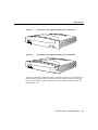
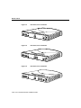
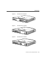
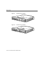
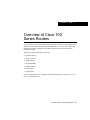
C H A PT E R
1
Overview of Cisco 700
Series Routers
Cisco 700 series routers connect Ethernet LANs to other networks over Integrated Services
Digital Network (ISDN) Basic Rate Interface (BRI) lines. Cisco 700 series routers offer
multiprotocol routing capability between WAN and LAN ports and can function as
transparent bridges.
This chapter contains the following sections:
•
•
•
•
•
•
•
Product Features
Security Features
SNMP Support
Supported MIBs
Supported RFCs
Router Panels
Specifications
For more information on the commands described in this chapter, refer to the Cisco 700
Series Command Reference.
Overview of Cisco 700 Series Routers 1-1
Product Features
Product Features
This section describes the major features of Cisco 700 series routers.
Dial-On-Demand Routing
Cisco 700 series routers include dial-on-demand routing (DDR). This allows the router to
dynamically initiate calls to remote devices across ISDN BRI lines as traffic demands. The
router also terminates ISDN connections based on the level of the traffic demanded on the
ISDN line and the dynamic routing parameters.
SPID and Switch Automatic Detection
The automatic service profile identifier (SPID) and switch detection feature simplifies the
use of ISDN terminal equipment and makes the equipment easier to use with fewer
parameters to enter. With this feature, the user only has to enter the local directory numbers
with area code. No SPID number or switch type is required from the user. The command
used is the set autodetection command.
The automatic detection feature only applies to ISDN switches for the USA and Canada,
usually an AT&T 5ESS Custom, DMS-100, NI-1, or NI-2 switch. The automatic detection
mechanism might not work with any other switch, such as a Siemens switch. The automatic
detection feature is only implemented in the U. S. image.
TFTP Client
Cisco 700 series routers support the use of a Trivial File Transfer Protocol (TFTP) client.
This feature increases TFTP file transfer efficiency and reliability. The swl tftp command
loads the TFTP client software from the console port.
1-2 Cisco 700 Series Router Installation Guide
Product Features
Profile-Based User Name and Password
Remote users often have multiple service providers. Connecting to different service
providers might require different user names and passwords. Previous releases of Cisco 700
software used the same user name and password for all profiles when making outgoing
Point-to-Point Protocol (PPP) connections. Cisco 700 series router software Release 4.1(1)
allows different profiles to have different user names and passwords.
In previous releases, the set systemname command set the system prompt and the PPP user
name when making outgoing PPP connections. Different profiles can now use different user
names when dialing out. A new profile level command, the set ppp clientname command,
has been created for this purpose.
Bandwidth Allocation Control Protocol and Bandwidth Allocation Protocol
The Bandwidth Allocation Control Protocol (BACP) and the Bandwidth Allocation
Protocol (BAP) define a set of rules to control dynamic bandwidth allocation gracefully by
managing the number of links in a PPP multilink bundle. BACP consists of a network
control protocol that negotiates once per PPP multilink bundle while BAP defines a set of
request and response messages to manage the links.
Cisco 700 series router software Release 4.0(2) already supports dynamic management of
both B channels with the demand feature. The implementation of BACP and BAP allows
Cisco 700 series routers to coordinate and negotiate the actual allocation and deallocation
of the second channel. The parameters are set using the demand command and the timeout
command.
BACP is only implemented on a BRI interface. A Multilink PPP has to be negotiated for
BACP to be functional.
If a data call is bumped to accommodate a voice call and if BAP negotiation is enforced,
the user might experience a short audio idle period before a B channel becomes available.
The user might not be able to connect the voice call if the peer declines to give up the link.
This happens when the set ppp bacp linkdrop negotiation command is set to ON.
Overview of Cisco 700 Series Routers 1-3
Product Features
NetBIOS Over TCP/IP Packet Filter
A generic filter capability on the Transaction Control Protocol/User Datagram Protocol
(TCP/UDP) packets allows users to filter NetBIOS packets generated by application
programs. Use the set ip filter command to control this feature.
NetBIOS Name Spoofing
When a WINS client sends out a NetBIOS Name query, the router can answer a NetBIOS
name query in place of the WINS server. If the router cannot answer, the router forwards
the query packets to the server, which forwards the response to the client. If spoofing is set,
the router keeps a local database of up to 100 Domain Name System (DNS) name entries
and has an aging scheme to age out the unused name entries.
Automatic Configuration From BOOTP
The automatic configuration feature allows the Cisco 700 series router to obtain a
configuration file from a remote server using BOOTP protocol. Upon power-up, the router
examines the Auto_Config flag stored in NVRAM. If the Auto_Config flag is FALSE, the
router initiates a BOOTP request for an IP address from the BOOTP server. If the BOOTP
server finds a matching MAC address, the server returns an IP address and a configuration
file name. The router initiates TFTP to download a configuration file.
After successfully loading the configuration file, the router sets the Auto_Config flag to
TRUE in NVRAM. In subsequence power-up operations, if the Auto_Config is TRUE, the
router does not initiate BOOTP. The set default command resets the Auto_Config flag to
FALSE.
The automatic configuration feature only works on the Ethernet interface. If the router does
not receive a BOOTP response from the server within 5 seconds of the first BOOTP request,
the router gives up and the Internet Protocol (IP) information must be configured manually.
DHCP Server
DHCP automates IP addressing and reduces the number of IP addresses a site might
require. Cisco 700 series routers can function as a dynamic host configuration protocol
(DHCP) server. (The router can also act as a DHCP relay, but not both at the same time.)
1-4 Cisco 700 Series Router Installation Guide
Product Features
When a DHCP server is enabled and configured, it assigns and manages IP addresses from
a specified address pool to DHCP clients. The options supported by this server are sufficient
for Windows 95 clients. If more IP addresses or options are required, a commercial DHCP
server (for example, Windows NT) should be used.
DHCP Relay Agent
Cisco 700 series routers can function as a DHCP relay agent. (The router can also act as a
DHCP server, but not both at the same time.) When configured, Cisco 700 series routers
relay DHCP requests and responses between DHCP clients and a specified DHCP server.
Use the set dhcp relay command, where the IP address is the address of the server to which
DHCP requests will be forwarded.
Port Address Translation
Cisco 700 series routers support port address translation (PAT) allowing a designated
private IP network to communicate with the outside world. When configured, Cisco 700
series routers translate source addresses from an IP private network to a single, global,
unique IP address before forwarding the packets to the outside world.
IP Address Assignment Through IPCP
The router can be assigned an IP address from the remote device using Internet Protocol
Control Protocol (IPCP) address negotiation. The implementation is based on RFC1332. It
supports IPCP options 1 and 3. (It does not support option 2, TCP/IP Header Compression.)
IP unnumbered is also supported. IPCP address negotiation is on by default in any profile
configured for IP routing. This feature does not support assigning addresses to remote
devices.
IP RIP Update Linkup
The IP Routing Information Protocol (RIP) Update Linkup option for IP RIP enables better
interoperability between the router and Cisco IOS software. If the IP RIP update is set to
link up for a WAN profile, the IP RIP data is sent as soon as a connection is established and
Overview of Cisco 700 Series Routers 1-5
Product Features
again every 30 seconds for as long as the connection exists. If the connection does not exist,
no RIP data is sent. This prevents the line from being brought up by RIP packets where the
update is periodic.
Force Dynamically Negotiated IP Addresses
When this feature is on, the negotiated IP address is assigned to the Standard or the
user-defined profile (whichever profile is used to place the call). It also tells the software to
try any IP address configured for this profile in the IP address negotiation.
When this feature is off and the internal profile does not contain an address, the negotiated
IP address is automatically assigned to the Internal profile by the system. If the Internal
profile contains an address, it will be assigned to the user-defined profile from which the
call was initiated. The parameters are set using the set ppp address negotiation command.
Fee Pulse Mode
Fee Pulse Mode manages the ISDN connection based on the paid periods of time. If other
thresholds indicate a call should be dropped due to low traffic, Fee Pulse Mode maintains
the connection until the current paid period has expired. Therefore, you are not paying full
price for part of a connection period. This feature is available only for NET3 (same as
ETSI) switch types, and you must subscribe to Advice of Charge-During Active Call
(AOC-D) supplementary service.
If the feature is enabled and idle time expires, the router checks the remaining time in the
current paid period. The router maintains the connection until the end of the paid period,
minus the disconnect time required to terminate the PPP and ISDN links.
If the idle time expires too close to the end of the paid period to close the connections before
the end of the paid period, the router extends the connection to the end of the next paid
period, minus disconnect time.
Call Transfer
Cisco 700 series routers can transfer an active voice call to another telephone number. For
more information on configuring call transfer, refer to the chapter “ISDN and Analog
Telephone Devices.”
1-6 Cisco 700 Series Router Installation Guide
Product Features
Call Forwarding (Sweden and Finland)
Call forwarding supplementary service has been added for Sweden and Finland (NET3).
Call forwarding is implemented differently in the European countries. The version
implemented here uses keypad procedures and is only partly ETSI-compliant.
Three-Way Call Conferencing
Cisco 700 series routers can add another party to an active voice call. You can connect three
people using this feature. For more information on configuring three-way call
conferencing, refer to the chapter “ISDN and Analog Telephone Devices.”
Data Call Button (Cisco 770 Series Router Only)
The data call button, located on the front panel of Cisco 770 series routers, provides an
alternative to establishing or disconnecting data calls through the command interface. The
data call button performs in Make or Break mode. If no B channels are connected for data,
and at least one B channel is available, the button works in Make mode and attempts to
establish a call. When at least one B channel is connected for data, the button works in
Break mode, disconnecting the call. Table 1-1 summarizes the operation of the Cisco 770
series data call button.
Table 1-1
Cisco 770 Series Data Call Button Operation Summary
Current
Status
No call up
1 data call
only
2 data calls
1 voice
call only
2 voice
calls
1 data and 1
voice call
Switch
Operation
Make a
data call
Disconnect
the data call
Disconnect
both data calls
Make a
data call
No
action
Disconnect
the data call
Second Number Fail-Over
Cisco 700 series routers can place a call to a backup telephone number when an outgoing
call is not successful because the receiving side is busy or does not answer. Cisco 700 series
routers support second number fail-over for manual and auto-data calls. The parameters are
set using the set backupnumber command.
Overview of Cisco 700 Series Routers 1-7
Product Features
IPX Support
To improve performance, only the services defined in Novell IPX Router Specification
107–000029–001 are supported, and a maximum of 400 IPX route entries and 200 IPX
SAPs are allowed. If you need more route and SAPs entries, software Release 4.0(1) and
higher supports set ipx sap helper and set ipx gateway commands.
IPX Ping
The IPX ping feature allows you to determine if the specified IPX node is alive and
reachable. Cisco 700 series routers only generate Novell IPX format ping packets when
IPX ping is sourced from the router. The response by the Cisco 700 series router to a Novell
IPX ping packet is in Novell IPX format. The response by the Cisco 700 series router to
Cisco IPX ping packets is in Cisco IPX format. (If a Novell NetWare server is pinged, the
specified server must be running the IPXPING.NLM to respond to the ping. This NLM
[NetWare Loadable Module] is part of an IPX Upgrade [IPXRTR.EXE] to NetWare
servers.) The parameters are set using the ipxping address command.
Default IPX Route
Cisco 700 series routers can route IPX packets to an established default gateway if no
learned or static route can be found for the destination in the routing table. The parameters
are set using the set ipx gateway command.
IPX SAP Filtering
IPX SAP filtering controls which services are added to the Cisco 700 series router Service
Advertisement Protocol (SAP) table. You can specify filters per type range or socket range.
Before a service is added to the SAP table, the service type and socket number for the
service is checked against the existing filters. If the type and socket ranges match any of the
existing filters, service is permitted or denied based on the action specified in the action
field of the filter. Otherwise (no filter matches the incoming service), the service is blocked.
If no filter is configured, all SAPs are permitted. The parameters are set using the set ipx
filter sap command. The maximum number of SAP filters is 20.
1-8 Cisco 700 Series Router Installation Guide
Security Features
Service Advertising Protocol (SAP) Helper
Cisco 700 series routers can forward to a specified router or server (instead of responding
to them) all SAP get-nearest-service request broadcast packets and get general service
request broadcast packets to an IPX router or IPX server as unicast packets. Cisco 700
series routers forward these request packets without looking in the local SAP table. The
parameters are set using the set ipx sap helper command.
Route Summarization
Route summarization is provided on IP RIP Version 2 (only Version 2 provides the required
subnet mask information). When route summarization is set to auto, the router summarizes
routes that cross the classful boundary to a single route based on the classful boundary.
When route summarization is set to off, the router uses the normal RIP Version 2 routes
with variable-length subnet masks (VLSMs). The default setting for RIP summarization is
OFF. Use the set ip rip summarization command to control this feature.
Data Compression
Cisco 700 series routers support data compression using the compression algorithm
QIC-122 standard, Stacker LZS. Data compression is a software configuration option that
optimizes the ISDN line bandwidth. Packets are compressed before being sent onto the
ISDN line. After they arrive at their destination, the packets are decompressed and sent on
to the remote LAN.
Security Features
Cisco 700 series routers provide the following security features:
•
PPP authentication support, including Password Authentication Protocol (PAP) and
Challenge Handshake Authentication Protocol (CHAP)
•
•
Password security for local and remote configuration access
IP filtering based on source and destination addresses, source and destination ports, and
packet types
Overview of Cisco 700 Series Routers 1-9
SNMP Support
Leased Line Authentication Requirement Removed
For 64-kbps or 128-kbps leased line connections, previous versions of the software required
PAP/CHAP authentication to identify the corresponding profile. In software Release 4.0(1)
and higher, the authentication sequence is no longer required for leased line connections.
To eliminate the need for authentication, a user-defined profile named leasedline must be
present and defined. If this profile is not present upon call connect, the router requires
authentication to select the correct profile. If the call cannot be authenticated, the router
defaults to the Standard profile.
Within the user-defined profile called leasedline, verify that PPP authentication is set to
none. The switch types that support this feature are PERM64 and PERM128.
SNMP Support
Cisco 700 series routers support Simple Network Management Protocol (SNMP).
SNMP Community Names
Cisco 700 series routers support the following SNMP community names:
•
•
•
•
•
public
proxy
private
regional
core
These community names are read-only and cannot be changed. Cisco 700 series routers do
not support SNMP set commands.
1-10 Cisco 700 Series Router Installation Guide
Supported MIBs
Supported MIBs
Cisco 700 series routers support the following SNMP Management Information Bases
(MIBs):
•
•
MIB II
IEEE 802.1d Bridge MIB
MIB II
Cisco 700 series routers support MIB II standards as follows:
•
•
•
•
•
•
•
•
System
Interfaces (all objects, except that a connection is considered to be an interface)
Address translation
Internet Protocol (IP)
Transmission Control Protocol (TCP)
Internet Control Message Protocol (ICMP)
User Datagram Protocol (UDP)
SNMP
IEEE 802.1d Bridge MIB
Cisco 700 series routers support IEEE 802.1d MIB standards as follows:
•
•
•
Base
Transparent bridging
Static
Overview of Cisco 700 Series Routers 1-11
Supported RFCs
Supported RFCs
Cisco 700 series routers support the following Request For Comments (RFC) documents:
•
•
•
•
•
•
•
•
•
•
•
•
RFC 1058—Routing Information Protocol (RIP)
RFC 1332—PPP Internet Protocol Control Protocol (IPCP)
RFC 1334—PPP Authentication Protocols
RFC 1541—Dynamic Host Configuration Protocol (DHCP)
RFC 1552—PPP Internetwork Packet Exchange
RFC 1570—PPP Link Control Protocol (LCP) Extensions
RFC 1582—Extensions to RIP to Support Demand Circuits
RFC 1618—PPP Over ISDN
RFC 1638—PPP Bridging Control Protocol (BCP)
RFC 1661—Point-to-Point Protocol (PPP)
RFC 1717—PPP Multilink Protocol (MP)
RFC 1723—Routing Information Protocol (RIP) Version 2—Carrying Additional
Information
Router Panels
Figure 1-1 and Figure 1-2 show the front panels of Cisco 760 series and Cisco 770 series
routers. Instructions for connecting the routers are provided in the Cisco 700 Quick
Reference Guide.
1-12 Cisco 700 Series Router Installation Guide
Router Panels
RD NT1 LINE
Front Panel, Cisco 760 Series Router (Cisco 766 Shown)
LAN RXD TXD
CH1 RXD
TXD
CH2 RXD
TXD
H5787
Figure 1-1
PH1 PH
2
Front Panel, Cisco 770 Series Router (Cisco 776 Shown)
H7990
Figure 1-2
Cisco 7
00
The ports for the Ethernet, ISDN S/T, ISDN U, and basic telephone service connections are
located on the rear panel of the Cisco 760 series router, as shown in Figure 1-3 through
Figure 1-6 and on the rear panel of the Cisco 770 series routers, as shown in Figure 1-7
through Figure 1-10.
Overview of Cisco 700 Series Routers 1-13
Router Panels
CONFIG
Rear Panel, Cisco 761 Router
H5906
Figure 1-3
10BASET
NODE
HUB
Link
ISDN S/T
+5V ---1.5A
+/-5%
-30V--- 0.2A
+/-25%
S0
CONFIG
Rear Panel, Cisco 762 Router
H5905
Figure 1-4
10BASET
NODE
HUB
Link
ISDN S/T
ISDN U
+5V ---1.5A
+/-5%
-30V--- 0.2A
+/-25%
S0
Figure 1-5
Rear Panel, Cisco 765 Router
10BASET
NODE
HUB
Link
H5789
CONFIG
NT-1
ISDN S/T
+5V ---1.5A
+/-5%
-30V--- 0.2A
+/-25%
S0
1-14 Cisco 700 Series Router Installation Guide
Router Panels
CONFIG
Rear Panel, Cisco 766 Router
H5788
Figure 1-6
10BASET
NODE
Link
HUB
ISDN S/T
ISDN U
+5V ---1.5A
+/-5%
-30V--- 0.2A
+/-25%
S0
CONFIG
Rear Panel, Cisco 771 Router
H8503
Figure 1-7
NT-1
4
10BASET
3
CISCO 771
2
1
ISDN S/T
+5V ---1.5A
+/-5%
-30V--- 0.2A
+/-25%
S0
CONFIG
Rear Panel, Cisco 772 Router
H8504
Figure 1-8
4
3
10BASET
CISCO 772
2
1
ISDN S/T
ISDN U
+5V ---1.5A
+/-5%
-30V--- 0.2A
+/-25%
S0
NT-1
Overview of Cisco 700 Series Routers 1-15
Router Panels
CONFIG
Rear Panel, Cisco 775 Router
H8502
Figure 1-9
4
3
10BASET
CISCO 775
2
1
ISDN S/T
+5V ---1.5A
+/-5%
-30V--- 0.2A
+/-25%
S0
CONFIG
Rear Panel, Cisco 776 Router
H7861
Figure 1-10
4
3
10BASET
CISCO 776
2
1
ISDN S/T
ISDN U
+5V ---1.5A
+/-5%
-30V--- 0.2A
+/-25%
S0
NT-1
1-16 Cisco 700 Series Router Installation Guide
Specifications
Specifications
The specifications for Cisco 700 series routers are listed in Table 1-2.
Table 1-2
System Specifications—Cisco 700 Series Routers
Description
Design Specification
(Height x Width x Depth)
1.6 x 8.3 x 9.6 inches (4.1 x 21.1 x 24.4 cm)
Weight
Cisco 761 and Cisco 771: 1.4 lb. (0.6 kg)
Cisco 762 and Cisco 772: 1.5 lb. (0.7 kg)
Cisco 765 and Cisco 775: 1.6 lb. (0.7 kg)
Cisco 766 and Cisco 776: 1.7 lb. (0.8 kg)
Power supply
External
Voltage
100 or 250 VAC
Frequency
50 to 60 Hz
Processor
25-MHz 80386
Memory
1.5 MB of primary memory
496 KB of Flash memory
16 KB of NVRAM
Ethernet interfaces
Ethernet 10BaseT, RJ-45
ISDN BRI interfaces
ISDN S/T, RJ-45
ISDN U, RJ-45
Analog telephone
interface
RJ-11
Configuration port
DB-9F (9-pin female)
Operating temperature
32 to 120°F (0 to 50°C)
Storage temperature
–30 to 160°F (–35 to 70°C)
Operating humidity
20 to 95%, noncondensing
Regulatory compliance
FCC Class B requirements and other compliance as outlined in
the Regulatory Compliance and Safety Information for
Cisco 700 Series Routers document shipped with your router
Overview of Cisco 700 Series Routers 1-17
Specifications
Table 1-3 lists the interfaces available on each Cisco 700 series router by model number.
Table 1-3
Cisco 700 Series Router Interfaces by Model
Model
Interfaces
Cisco 761
1 Ethernet and 1 ISDN BRI S/T
Cisco 762
1 Ethernet, 1 ISDN BRI S/T, and 1 ISDN BRI U
Cisco 765
1 Ethernet, 1 ISDN BRI S/T, and 2 analog telephone
Cisco 766
1 Ethernet, 1 ISDN BRI S/T, 1 ISDN BRI U, and 2 analog telephone
Cisco 771
4 port unmanaged Ethernet hub and 1 ISDN BRI S/T
Cisco 772
4 port unmanaged Ethernet hub, 1 ISDN BRI S/T, and 1 ISDN BRI U
Cisco 775
4 port unmanaged Ethernet hub, 1 ISDN BRI S/T, and
2 analog telephone
Cisco 776
4 port unmanaged Ethernet hub, 1 ISDN BRI S/T, 1 ISDN BRI U,
and 2 analog telephone
1-18 Cisco 700 Series Router Installation Guide