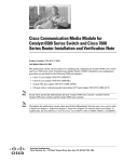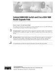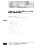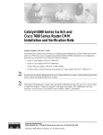
1
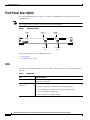
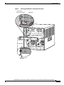
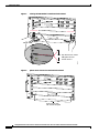
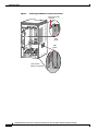
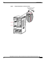
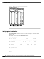
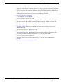
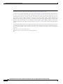
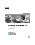
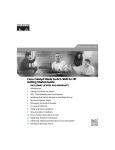
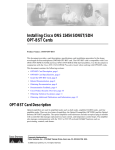
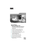
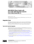
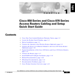
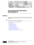
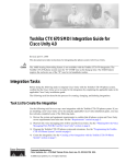
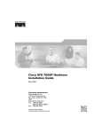
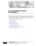
Catalyst 6500 Series Switch and Cisco 7600
Series Router Wireless Services Module
Installation and Verification Note
Product number: WS-SVC-WiSM-1-K9
This document provides installation procedures for the Catalyst 6500 Series Switch and Cisco 7600
Series Router Wireless Services Module (WiSM).
Contents
This publication contains these sections:
•
Front Panel Description, page 2
•
System Requirements, page 3
•
Safety Overview, page 4
•
Required Tools, page 4
•
Installing the WiSM, page 5
•
Verifying the Installation, page 12
•
Removing the WiSM, page 13
•
Regulatory Standards Compliance, page 14
•
Related Documentation, page 14
•
Obtaining Documentation, page 14
•
Documentation Feedback, page 15
•
Cisco Product Security Overview, page 15
•
Obtaining Technical Assistance, page 16
•
Obtaining Additional Publications and Information, page 18
Corporate Headquarters:
Cisco Systems, Inc., 170 West Tasman Drive, San Jose, CA 95134-1706 USA
© 2005–2006 Cisco Systems, Inc. All rights reserved.
Front Panel Description
Front Panel Description
The Cisco WiSM front panel (see Figure 1) includes a POWER LED, two STATUS LEDs, and two
CONSOLE ports.
The Compact Flash is internal; it is not a field-replaceable unit (FRU).
Figure 1
WiSM Front Panel
Status 1
LED
Power
LED
Status 2
LED
STATUS 1
POWER
STATUS 2
DISK 2
DISK 1
CONSOLE 1
Console 1
port
CONSOLE 2
137548
Note
Console 2
port
These sections describe the Cisco WiSM front panel:
•
LEDs, page 2
•
CONSOLE Ports, page 3
LEDs
The LEDs on the WiSM front panel indicate the status of the module. Table 1 lists the LEDs and their
functions.
Table 1
WiSM LEDs
LED
Color/Description
POWER
The POWER LED is green when the module is receiving power and is off
when power is removed.
STATUS 1
STATUS 2
The STATUS LEDs shows the status as follows:
•
Orange—Booting the bootloader and running diagnostics
•
Green (flashing)—Software is accessing the Compact Flash
•
Green—Controller is initializing
•
Off—Controller is running normally
Catalyst 6500 Series Switch and Cisco 7600 Series Router Wireless Services Module Installation and Verification Note
2
78-17121-04
System Requirements
CONSOLE Ports
The CONSOLE ports allow you to access each controller either locally (with a console terminal) or
remotely (with a modem). The CONSOLE ports are EIA/TIA-232 asynchronous, serial connections with
hardware flow control and RJ-45 connectors.
System Requirements
These sections describe the hardware and software requirements:
•
Hardware Components, page 3
•
Power Requirements, page 3
•
Software Requirements, page 4
Hardware Components
The Catalyst 6500 series or Cisco 7609 or 7613 chassis in which the Cisco WiSM is installed requires a
Supervisor 720 module. The supported slots for the Cisco WiSM are listed in Table 2.
Table 2
Supported Slots for the Cisco WiSM
Slot
Catalyst 6503
Catalyst 6504
Catalyst 6506
Catalyst 6509
Cisco 7609
Catalyst 6513
Cisco 7613
1–3
x
x
x
x
–
4
–
x
x
x
–
5–6
–
–
x
–
–
7–8
–
–
–
x
–
9
–
–
–
x
x
10–13
–
–
–
–
x
Power Requirements
The Cisco WiSM module requires 254W for operation. Make sure that your chassis can provide this
power.
Note
All Catalyst 6500 chassis (except the Catalyst 6503) require the fan tray 2 module, which requires the
2500W power supply for proper operation. For planning purposes, be aware that the 2500Wt power
supply requires a 20A input power circuit with a NEMA plug.
You can use the show power command to view power details for your installation, including the system
power available and power statistics for installed power supplies and cards.
Catalyst 6500 Series Switch and Cisco 7600 Series Router Wireless Services Module Installation and Verification Note
78-17121-04
3
Safety Overview
Software Requirements
Before you install the WiSM into the chassis, make sure that the module and the chassis meet the
software requirements. Refer to the Release Notes for Cisco Wireless LAN Controllers and Lightweight
Access Points at this URL:
http://www.cisco.com/univercd/cc/td/doc/product/wireless/control/c44/index.htm
Safety Overview
Safety warnings appear throughout this publication in procedures that, if performed incorrectly, may
harm you. A warning symbol precedes each warning statement.
Warning
IMPORTANT SAFETY INSTRUCTIONS
This warning symbol means danger. You are in a situation that could cause bodily injury. Before you
work on any equipment, be aware of the hazards involved with electrical circuitry and be familiar
with standard practices for preventing accidents. Use the statement number provided at the end of
each warning to locate its translation in the translated safety warnings that accompanied this
device. Statement 1071
SAVE THESE INSTRUCTIONS
Warning
Only trained and qualified personnel should be allowed to install, replace, or service this equipment.
Statement 1030
Warning
Blank faceplates and cover panels serve three important functions: they prevent exposure to
hazardous voltages and currents inside the chassis; they contain electromagnetic interference (EMI)
that might disrupt other equipment; and they direct the flow of cooling air through the chassis. Do not
operate the system unless all cards, faceplates, front covers, and rear covers are in place.
Statement 1029
Required Tools
These tools are required to install the WiSM in the Catalyst 6500 series switches or the Cisco 7600 series
routers:
•
Number 2 Phillips screwdriver
•
Antistatic mat or antistatic foam
•
Your own electrostatic discharge (ESD) grounding strap or the disposable ESD strap included with
the system
Catalyst 6500 Series Switch and Cisco 7600 Series Router Wireless Services Module Installation and Verification Note
4
78-17121-04
Installing the WiSM
Warning
Blank faceplates and cover panels serve three important functions: they prevent exposure to
hazardous voltages and currents inside the chassis; they contain electromagnetic interference (EMI)
that might disrupt other equipment; and they direct the flow of cooling air through the chassis. Do not
operate the system unless all cards, faceplates, front covers, and rear covers are in place.
Statement 1029
Installing the WiSM
This section describes how to install the WiSM in the Catalyst 6500 series switches or the Cisco 7600
series routers.
Caution
Note
To prevent ESD damage, handle modules by the carrier edges only and wear grounding wrist straps.
Specific combinations of supervisor engines and modules may not be supported in your chassis. Refer
to the release notes of the software version running on your system for specific information on modules
and supervisor engine combinations that are not supported.
To install the WiSM in the chassis, follow these steps:
Step 1
Choose a slot for the WiSM.
Step 2
Verify that there is enough clearance to accommodate any interface equipment that you will connect
directly to the WiSM ports. If possible, place modules between empty slots that contain only module
filler plates.
Step 3
Verify that the captive installation screws are tightened on all modules installed in the chassis. This
assures that the EMI gaskets on all modules are fully compressed in order to maximize the opening space
for the new module or the replacement module.
Note
If the captive installation screws are loose, the EMI gaskets on the installed modules will push
adjacent modules toward the open slot, reducing the opening size and making it difficult to
install the replacement module.
Step 4
Remove the module filler plate by removing the two Phillips pan-head screws from the filler plate.
To remove a module, see the “Removing the WiSM” section on page 13.
Step 5
Fully open both ejector levers on the WiSM. (See Figure 2.)
Step 6
Depending on the orientation of the slots in the chassis (horizontal or vertical), perform one of the
following two sets of substeps.
Catalyst 6500 Series Switch and Cisco 7600 Series Router Wireless Services Module Installation and Verification Note
78-17121-04
5
Installing the WiSM
Horizontal slots
Caution
a.
Position the WiSM in the slot. (See Figure 2.) Make sure that you align the sides of the module
carrier with the slot guides on each side of the slot.
b.
Carefully slide the WiSM into the slot until the EMI gasket along the top edge of the module makes
contact with the module in the slot above it and both ejector levers have closed to approximately 45
degrees with respect to the module faceplate. (See Figure 3.)
c.
Using the thumb and forefinger of each hand, grasp the two ejector levers and press down to create
a small (0.040 inch [1 mm]) gap between the module’s EMI gasket and the module above it.
(See Figure 3.)
Do not press down too hard on the levers. They will bend and be damaged.
d.
Note
e.
Note
f.
While pressing down, simultaneously close the left and right ejector levers to fully seat the
supervisor engine or module in the backplane connector. The ejector levers are fully closed when
they are flush with the module faceplate. (See Figure 4.)
Failure to fully seat the module in the backplane connector can result in error messages.
Tighten the two captive installation screws on the WiSM.
Make sure the ejector levers are fully closed before tightening the captive installation screws.
Verify that the WiSM STATUS LED is lit. Check the STATUS LED periodically. If the STATUS
LED changes from orange to green, the WiSM has successfully completed the boot process and is
now online. If the STATUS LED remains orange or turns red, the WiSM has not successfully
completed the boot process and may have encountered an error.
Catalyst 6500 Series Switch and Cisco 7600 Series Router Wireless Services Module Installation and Verification Note
6
78-17121-04
Installing the WiSM
Figure 2
Positioning the Module in a Horizontal Slot Chassis
Insert module
between slot guides
EMI gasket
3
4
5
6
4
5
6
WS-X6K-SUP2-2GE
1
T
E
US
NS
ST
SY
GM
OL
EM
AT
ST
R
CO
M
Switch
100%
T
SE
PW
Load
CONSOLE
PORT
MODE
RE
PORT 1
PORT 2
CONSOLE
SUPERVISOR2
PCMCIA
EJECT
1%
WS-X6K-SUP2-2GE
2
T
E
US
NS
ST
SY
GM
OL
EM
AT
ST
CO
R
PW
M
Switch
100%
T
SE
Load
CONSOLE
PORT
MODE
RE
PORT 1
PORT 2
CONSOLE
SUPERVISOR2
PCMCIA
EJECT
1%
3
4
FAN
STATUS 5
6
WS-X6224
US
VE
AT
TI
AC
SE
LE
24 PORT 100FX
NE
EMI gasket
CT
XT
58569
ST
o
o
INPUT
OK
FAN
OK
OUTPUT
FAIL
INPUT
OK
FAN
OK
OUTPUT
FAIL
WS-C6500-SFM
US
AT
ST
E
TIV
AC
SWITCH FABRIC MDL
Ejector lever fully
extended
Catalyst 6500 Series Switch and Cisco 7600 Series Router Wireless Services Module Installation and Verification Note
78-17121-04
7
Installing the WiSM
Figure 3
Clearing the EMI Gasket in a Horizontal Slot Chassis
WS-X6K-SUP2-2GE
1
US
AT
ST
LE
EM
ST
SY
O
NS
CO
PW
M
R
G
M
T
Switch
100%
T
SE
RE
CONSOLE
Load
CONSOLE
PORT
MODE
PORT 1
SUPERVISOR2
PCMCIA
PORT 2
EJECT
1%
WS-X6K-SUP2-2GE
NK
NK
LI
2
US
AT
ST
EM
ST
SY
M
G
O
NS
CO
LI
T
LE
M
R
PW
Switch
100%
T
SE
RE
CONSOLE
Load
CONSOLE
PORT
MODE
PORT 1
SUPERVISOR2
PCMCIA
PORT 2
EJECT
1%
NK
NK
LI
LI
3
Press down
4
FAN
STATUS 5
Press down
WS-X6224
S
TU
VE
TI
STA
AC
CT
LE
SE
24 PORT 100FX
XT
NE
6
3
4
4
WS-C6500-SFM
5
5
US
1 mm Gap between the module
EMI gasket and the
module above it
E
AT
TIV
ST
AC
SWITCH FABIR
6
Figure 4
58570
D MDL
6
Ejector Lever Closure in a Horizontal Slot Chassis
WS-X6K-SUP2-2GE
1
US
AT
ST
LE
EM
ST
SY
O
NS
CO
PW
R
M
G
M
T
Switch
100%
T
SE
RE
CONSOLE
SUPERVISOR2
Load
CONSOLE
PORT
MODE
PORT 1
PCMCIA
PORT 2
EJECT
1%
WS-X6K-SUP2-2GE
NK
LI
2
US
AT
ST
LE
EM
ST
SY
O
NS
CO
PW
R
M
G
M
NK
LI
T
Switch
100%
T
SE
RE
CONSOLE
SUPERVISOR2
Load
CONSOLE
PORT
MODE
PORT 1
PCMCIA
PORT 2
EJECT
1%
NK
LI
NK
LI
3
4
FAN
STATUS 5
WS-C6500-SFM
S
TU
STA
CT
VE
TI
AC
LE
SE
SWITCH FABRIC MDL
XT
NE
58571
6
Ejector levers flush
with module faceplate
Catalyst 6500 Series Switch and Cisco 7600 Series Router Wireless Services Module Installation and Verification Note
8
78-17121-04
Installing the WiSM
Vertical slots
Caution
a.
Position the supervisor engine or switching module in the slot. (See Figure 5.) Make sure that you
align the sides of the switching-module carrier with the slot guides on the top and bottom of the slot.
b.
Carefully slide the WiSM into the slot until the EMI gasket along the right edge of the module makes
contact with the module in the slot adjacent to it and both ejector levers have closed to
approximately 45 degrees with respect to the module faceplate. (See Figure 6.)
c.
Using the thumb and forefinger of each hand, grasp the two ejector levers and exert a slight pressure
to the left, deflecting the module approximately 0.04 inches (1 mm) to create a small gap between
the module’s EMI gasket and the module adjacent to it. (See Figure 6.)
Do not exert too much pressure on the ejector levers. They will bend and be damaged.
d.
While pressing on the ejector levers, simultaneously close them to fully seat the WiSM in the
backplane connector. The ejector levers are fully closed when they are flush with the module
faceplate. (See Figure 7.)
e.
Tighten the two captive installation screws on the module.
Note
Make sure that the ejector levers are fully closed before tightening the captive installation
screws.
f.
Verify that the WiSM STATUS LED is lit. Check the STATUS LED periodically. If the STATUS
LED changes from orange to green, the WiSM has successfully completed the boot process and is
now online. If the STATUS LED remains orange or turns red, the WiSM has not successfully
completed the boot process and may have encountered an error.
Catalyst 6500 Series Switch and Cisco 7600 Series Router Wireless Services Module Installation and Verification Note
78-17121-04
9
Installing the WiSM
Figure 5
Positioning the Module in a Vertical Slot Chassis
Ejector lever fully
extended
WS-C6500-SFM
SWITCH FABRIC MDL
FAN
STATUS
WS-X6K-SUP2-2GE
MT
E
M
S
OL
T
MG
TU
R
NS
SE
STE
RE
PW
CO
SY
STA
MT
OLE MG
TEM NS
TUS
R
SET
RE
PW
SYS
CO
STA
WS-X6K-SUP2-2GE
SUPERVISOR2
SUPERVISOR2
ST
AT
CONSOLE
CONSOLE
US
AC
PORT
MODE
PORT
MODE
CONSOLE
WS-X6224
24 PORT 100FX
CONSOLE
TIV
E
US
AT
ST
E
TIV
AC
PCMCIA
PCMCIA
EJECT
EJECT
Switch
Switch
1%
100%
1%
100%
Load
Load
EMI
gasket
PORT 1
PORT 1
PORT 2
PORT 2
CT
LE
XT
SE
NE
63585
EMI
gasket
o
o
INPUT
OK
FAN
OK
OUTPUT
FAIL
INPUT
OK
FAN
OK
OUTPUT
FAIL
6
Insert module
between slot guides
3
4
Catalyst 6500 Series Switch and Cisco 7600 Series Router Wireless Services Module Installation and Verification Note
10
78-17121-04
Installing the WiSM
Figure 6
Clearing the EMI Gasket in a Vertical Slot Chassis
Gap between the module
EMI gasket and the
module above it
1 mm
WS-C6500-SFM
SWITCH FABIRD MDL
S
TU
A
ST
E
TIV
AC
FAN
STATUS
WS-X6K-SUP2-2GE
MT
E
M
S
OL
T
MG
TU
R
NS
SE
STE
RE
PW
CO
SY
STA
US
AT
ST
MT
OLE MG
TEM NS
TUS
R
SET
RE
PW
SYS
CO
STA
WS-X6K-SUP2-2GE
SUPERVISOR2
SUPERVISOR2
WS-X6224
24 PORT 100FX
CONSOLE
CONSOLE
E
TIV
AC
PORT
MODE
PORT
MODE
CONSOLE
CONSOLE
Press left
PCMCIA
PCMCIA
EJECT
EJECT
Switch
Switch
1%
100%
1%
100%
Load
Load
PORT 1
PORT 1
CT
LE
SE
XT
NE
Press left
63586
PORT 2
PORT 2
o
o
INPUT
OK
FAN
OK
OUTPUT
FAIL
INPUT
OK
FAN
OK
OUTPUT
FAIL
Catalyst 6500 Series Switch and Cisco 7600 Series Router Wireless Services Module Installation and Verification Note
78-17121-04
11
Verifying the Installation
Figure 7
Ejector Lever Closure in a Vertical Slot Chassis
FAN
STATUS
T
M
LE
G
O
T
M
EM
US
R
NS
SE
ST
AT
RE
PW
SY
CO
ST
CO
EM
ST
SY
O
NS
PW
LE
STA
R
T
CONSOLE
CONSOLE
VE
TI
AC
SE
T
M
RE
G
S
M
TU
CONSOLE
PORT
MODE
CONSOLE
PORT
MODE
PCMCIA
PCMCIA
EJECT
EJECT
1%
Switch
Switch
100%
1%
100%
Load
Load
PORT 1
PORT 1
XT
WS-X6K-SUP2-2GE
SUPERVISOR2
US
AT
ST
WS-X6K-SUP2-2GE
SUPERVISOR2
WS-X6224
24 PORT 100FX
NE
SE
LE
CT
63587
PORT 2
PORT 2
All ejector levers flush
with module faceplate
Verifying the Installation
Enter the show module command to verify that the system acknowledges the new module and has
brought it online.
This example shows the output of the show module command:
Router> show module 2
Mod Ports Card Type
Model
Serial No.
--- ----- -------------------------------------- ------------------ ----------2
10 Wireless Services Module
WS-SVC-WISM-1-K9
SAD092504JJ
Mod MAC addresses
--- ---------------------------------2 0001.0002.0003 to 0001.0002.0012
Hw
Fw
Sw
Status
----- ------------ ------------ ------0.1
12.2(14r)S5 12.2
Ok
Mod Sub-Module
Model
Serial
Hw
Status
--- --------------------------- ------------------ ------------ ------- ------2 Centralized Forwarding Card WS-F6700-CFC
SAD092608SY 0.2
Ok
Mod Online Diag Status
--- ------------------2 Pass
Router>
Catalyst 6500 Series Switch and Cisco 7600 Series Router Wireless Services Module Installation and Verification Note
12
78-17121-04
Removing the WiSM
Removing the WiSM
This section describes how to remove an existing WiSM from a chassis slot.
Caution
Do not remove the Cisco WiSM from the chassis until the module has shut down completely and the
STATUS LED is orange or off. You can damage the module if you remove it from the chassis before it
completely shuts down.
Caution
During this procedure, wear grounding wrist straps to avoid ESD damage to the card.
To remove a WiSM from the chassis, follow these steps:
Step 1
In configuration mode from the router prompt, enter the no power enable module mod command.
Note
Shutdown may require several minutes.
Step 2
Verify that the WiSM is down. Do not remove the module from the switch until the STATUS LEDs are
off or orange.
Step 3
Use a screwdriver to loosen the captive installation screws at the left and right sides of the module.
Step 4
Grasp the left and right ejector levers. Simultaneously, pull the left lever to the left and the right lever to
the right to release the module from the backplane connector.
Step 5
As you pull the module out of the slot, place one hand under the carrier to support it. Avoid touching the
module itself.
Step 6
Carefully pull the module straight out of the slot, keeping one hand under the carrier to guide it. Keep
the module at a 90-degree orientation to the backplane (horizontal to the floor).
Step 7
Place the removed module on an antistatic mat or antistatic foam.
Warning
Blank faceplates and cover panels serve three important functions: they prevent exposure to
hazardous voltages and currents inside the chassis; they contain electromagnetic interference (EMI)
that might disrupt other equipment; and they direct the flow of cooling air through the chassis. Do not
operate the system unless all cards, faceplates, front covers, and rear covers are in place.
Statement 1029
Step 8
If the slot is to remain empty, install a module filler plate to keep dust out of the chassis and to maintain
proper airflow through the module compartment.
Configuring the WiSM
For information on configuring the WiSM, refer to the Cisco Wireless LAN Controller
Configuration Guide and the Cisco Wireless LAN Controller Command Reference at this URL:
http://www.cisco.com/univercd/cc/td/doc/product/wireless/control/c44/index.htm
Catalyst 6500 Series Switch and Cisco 7600 Series Router Wireless Services Module Installation and Verification Note
78-17121-04
13
Regulatory Standards Compliance
Regulatory Standards Compliance
Catalyst 6500 series switching modules comply with the regulatory standards listed in the Regulatory
Compliance and Safety Information for the Catalyst 6500 Series Switches publication. Cisco 7600 series
routers comply with the regulatory standards listed in the Regulatory Compliance and Safety
Information for the Cisco 7600 Series Router publication.
Related Documentation
For more detailed installation and configuration information, refer to these publications:
•
Regulatory Compliance and Safety Information for the Catalyst 6500 Series Switches
•
Regulatory Compliance and Safety Information for the Cisco 7600 Series Router
•
Catalyst 6500 Series Switch Module Installation Guide
•
Catalyst 6500 Series Switch Cisco IOS Software Configuration Guide
•
Catalyst 6500 Series Switch Software Configuration Guide
•
Catalyst 6500 Series Switch Command Reference
•
Cisco 7600 Series Router Installation Guide
•
Cisco 7600 Series Router Software Configuration Guide
•
Cisco 7600 Series Router Command Reference
•
Cisco Wireless LAN Controller Configuration Guide
•
Cisco Wireless LAN Controller Command Reference
•
Release Notes for Cisco Wireless LAN Controllers and Lightweight Access Points
Obtaining Documentation
Cisco documentation and additional literature are available on Cisco.com. Cisco also provides several
ways to obtain technical assistance and other technical resources. These sections explain how to obtain
technical information from Cisco Systems.
Cisco.com
You can access the most current Cisco documentation at this URL:
http://www.cisco.com/techsupport
You can access the Cisco website at this URL:
http://www.cisco.com
You can access international Cisco websites at this URL:
http://www.cisco.com/public/countries_languages.shtml
Catalyst 6500 Series Switch and Cisco 7600 Series Router Wireless Services Module Installation and Verification Note
14
78-17121-04
Documentation Feedback
Product Documentation DVD
The Product Documentation DVD is a comprehensive library of technical product documentation on a
portable medium. The DVD enables you to access multiple versions of installation, configuration, and
command guides for Cisco hardware and software products. With the DVD, you have access to the same
HTML documentation that is found on the Cisco website without being connected to the Internet.
Certain products also have .PDF versions of the documentation available.
The Product Documentation DVD is available as a single unit or as a subscription. Registered Cisco.com
users (Cisco direct customers) can order a Product Documentation DVD (product number
DOC-DOCDVD= or DOC-DOCDVD=SUB) from Cisco Marketplace at this URL:
http://www.cisco.com/go/marketplace/
Ordering Documentation
Registered Cisco.com users may order Cisco documentation at the Product Documentation Store in the
Cisco Marketplace at this URL:
http://www.cisco.com/go/marketplace/
Nonregistered Cisco.com users can order technical documentation from 8:00 a.m. to 5:00 p.m.
(0800 to 1700) PDT by calling 1 866 463-3487 in the United States and Canada, or elsewhere by
calling 011 408 519-5055. You can also order documentation by e-mail at
[email protected] or by fax at 1 408 519-5001 in the United States and Canada,
or elsewhere at 011 408 519-5001.
Documentation Feedback
You can rate and provide feedback about Cisco technical documents by completing the online feedback
form that appears with the technical documents on Cisco.com.
You can submit comments about Cisco documentation by using the response card (if present) behind the
front cover of your document or by writing to the following address:
Cisco Systems
Attn: Customer Document Ordering
170 West Tasman Drive
San Jose, CA 95134-9883
We appreciate your comments.
Cisco Product Security Overview
Cisco provides a free online Security Vulnerability Policy portal at this URL:
http://www.cisco.com/en/US/products/products_security_vulnerability_policy.html
From this site, you will find information about how to:
•
Report security vulnerabilities in Cisco products.
•
Obtain assistance with security incidents that involve Cisco products.
•
Register to receive security information from Cisco.
Catalyst 6500 Series Switch and Cisco 7600 Series Router Wireless Services Module Installation and Verification Note
78-17121-04
15
Obtaining Technical Assistance
A current list of security advisories, security notices, and security responses for Cisco products is
available at this URL:
http://www.cisco.com/go/psirt
To see security advisories, security notices, and security responses as they are updated in real time, you
can subscribe to the Product Security Incident Response Team Really Simple Syndication (PSIRT RSS)
feed. Information about how to subscribe to the PSIRT RSS feed is found at this URL:
http://www.cisco.com/en/US/products/products_psirt_rss_feed.html
Reporting Security Problems in Cisco Products
Cisco is committed to delivering secure products. We test our products internally before we release them,
and we strive to correct all vulnerabilities quickly. If you think that you have identified a vulnerability
in a Cisco product, contact PSIRT:
•
For Emergencies only — [email protected]
An emergency is either a condition in which a system is under active attack or a condition for which
a severe and urgent security vulnerability should be reported. All other conditions are considered
nonemergencies.
•
For Nonemergencies — [email protected]
In an emergency, you can also reach PSIRT by telephone:
Tip
•
1 877 228-7302
•
1 408 525-6532
We encourage you to use Pretty Good Privacy (PGP) or a compatible product (for example, GnuPG) to
encrypt any sensitive information that you send to Cisco. PSIRT can work with information that has been
encrypted with PGP versions 2.x through 9.x.
Never use a revoked or an expired encryption key. The correct public key to use in your correspondence
with PSIRT is the one linked in the Contact Summary section of the Security Vulnerability Policy page
at this URL:
http://www.cisco.com/en/US/products/products_security_vulnerability_policy.html
The link on this page has the current PGP key ID in use.
If you do not have or use PGP, contact PSIRT at the aforementioned e-mail addresses or phone numbers
before sending any sensitive material to find other means of encrypting the data.
Obtaining Technical Assistance
Cisco Technical Support provides 24-hour-a-day award-winning technical assistance. The Cisco
Technical Support & Documentation website on Cisco.com features extensive online support resources.
In addition, if you have a valid Cisco service contract, Cisco Technical Assistance Center (TAC)
engineers provide telephone support. If you do not have a valid Cisco service contract, contact your
reseller.
Catalyst 6500 Series Switch and Cisco 7600 Series Router Wireless Services Module Installation and Verification Note
16
78-17121-04
Obtaining Technical Assistance
Cisco Technical Support & Documentation Website
The Cisco Technical Support & Documentation website provides online documents and tools for
troubleshooting and resolving technical issues with Cisco products and technologies. The website is
available 24 hours a day, at this URL:
http://www.cisco.com/techsupport
Access to all tools on the Cisco Technical Support & Documentation website requires a Cisco.com user
ID and password. If you have a valid service contract but do not have a user ID or password, you can
register at this URL:
http://tools.cisco.com/RPF/register/register.do
Note
Use the Cisco Product Identification (CPI) tool to locate your product serial number before submitting
a web or phone request for service. You can access the CPI tool from the Cisco Technical Support &
Documentation website by clicking the Tools & Resources link under Documentation & Tools. Choose
Cisco Product Identification Tool from the Alphabetical Index drop-down list, or click the Cisco
Product Identification Tool link under Alerts & RMAs. The CPI tool offers three search options: by
product ID or model name; by tree view; or for certain products, by copying and pasting show command
output. Search results show an illustration of your product with the serial number label location
highlighted. Locate the serial number label on your product and record the information before placing a
service call.
Submitting a Service Request
Using the online TAC Service Request Tool is the fastest way to open S3 and S4 service requests. (S3
and S4 service requests are those in which your network is minimally impaired or for which you require
product information.) After you describe your situation, the TAC Service Request Tool provides
recommended solutions. If your issue is not resolved using the recommended resources, your service
request is assigned to a Cisco engineer. The TAC Service Request Tool is located at this URL:
http://www.cisco.com/techsupport/servicerequest
For S1 or S2 service requests, or if you do not have Internet access, contact the Cisco TAC by telephone.
(S1 or S2 service requests are those in which your production network is down or severely degraded.)
Cisco engineers are assigned immediately to S1 and S2 service requests to help keep your business
operations running smoothly.
To open a service request by telephone, use one of the following numbers:
Asia-Pacific: +61 2 8446 7411 (Australia: 1 800 805 227)
EMEA: +32 2 704 55 55
USA: 1 800 553-2447
For a complete list of Cisco TAC contacts, go to this URL:
http://www.cisco.com/techsupport/contacts
Catalyst 6500 Series Switch and Cisco 7600 Series Router Wireless Services Module Installation and Verification Note
78-17121-04
17
Obtaining Additional Publications and Information
Definitions of Service Request Severity
To ensure that all service requests are reported in a standard format, Cisco has established severity
definitions.
Severity 1 (S1)—An existing network is down, or there is a critical impact to your business operations.
You and Cisco will commit all necessary resources around the clock to resolve the situation.
Severity 2 (S2)—Operation of an existing network is severely degraded, or significant aspects of your
business operations are negatively affected by inadequate performance of Cisco products. You and Cisco
will commit full-time resources during normal business hours to resolve the situation.
Severity 3 (S3)—Operational performance of the network is impaired, while most business operations
remain functional. You and Cisco will commit resources during normal business hours to restore service
to satisfactory levels.
Severity 4 (S4)—You require information or assistance with Cisco product capabilities, installation, or
configuration. There is little or no effect on your business operations.
Obtaining Additional Publications and Information
Information about Cisco products, technologies, and network solutions is available from various online
and printed sources.
•
The Cisco Product Quick Reference Guide is a handy, compact reference tool that includes brief
product overviews, key features, sample part numbers, and abbreviated technical specifications for
many Cisco products that are sold through channel partners. It is updated twice a year and includes
the latest Cisco offerings. To order and find out more about the Cisco Product Quick Reference
Guide, go to this URL:
http://www.cisco.com/go/guide
•
Cisco Marketplace provides a variety of Cisco books, reference guides, documentation, and logo
merchandise. Visit Cisco Marketplace, the company store, at this URL:
http://www.cisco.com/go/marketplace/
•
Cisco Press publishes a wide range of general networking, training and certification titles. Both new
and experienced users will benefit from these publications. For current Cisco Press titles and other
information, go to Cisco Press at this URL:
http://www.ciscopress.com
•
Packet magazine is the Cisco Systems technical user magazine for maximizing Internet and
networking investments. Each quarter, Packet delivers coverage of the latest industry trends,
technology breakthroughs, and Cisco products and solutions, as well as network deployment and
troubleshooting tips, configuration examples, customer case studies, certification and training
information, and links to scores of in-depth online resources. You can access Packet magazine at
this URL:
http://www.cisco.com/packet
Catalyst 6500 Series Switch and Cisco 7600 Series Router Wireless Services Module Installation and Verification Note
18
78-17121-04
Obtaining Additional Publications and Information
•
iQ Magazine is the quarterly publication from Cisco Systems designed to help growing companies
learn how they can use technology to increase revenue, streamline their business, and expand
services. The publication identifies the challenges facing these companies and the technologies to
help solve them, using real-world case studies and business strategies to help readers make sound
technology investment decisions. You can access iQ Magazine at this URL:
http://www.cisco.com/go/iqmagazine
or view the digital edition at this URL:
http://ciscoiq.texterity.com/ciscoiq/sample/
•
Internet Protocol Journal is a quarterly journal published by Cisco Systems for engineering
professionals involved in designing, developing, and operating public and private internets and
intranets. You can access the Internet Protocol Journal at this URL:
http://www.cisco.com/ipj
•
Networking products offered by Cisco Systems, as well as customer support services, can be
obtained at this URL:
http://www.cisco.com/en/US/products/index.html
•
Networking Professionals Connection is an interactive website for networking professionals to
share questions, suggestions, and information about networking products and technologies with
Cisco experts and other networking professionals. Join a discussion at this URL:
http://www.cisco.com/discuss/networking
•
World-class networking training is available from Cisco. You can view current offerings at
this URL:
http://www.cisco.com/en/US/learning/index.html
Catalyst 6500 Series Switch and Cisco 7600 Series Router Wireless Services Module Installation and Verification Note
78-17121-04
19
Obtaining Additional Publications and Information
This document is to be used in conjunction with the documents listed in the “Related Documentation” section.
CCVP, the Cisco Logo, and the Cisco Square Bridge logo are trademarks of Cisco Systems, Inc.; Changing the Way We Work, Live, Play, and Learn is a
service mark of Cisco Systems, Inc.; and Access Registrar, Aironet, BPX, Catalyst, CCDA, CCDP, CCIE, CCIP, CCNA, CCNP, CCSP, Cisco, the Cisco
Certified Internetwork Expert logo, Cisco IOS, Cisco Press, Cisco Systems, Cisco Systems Capital, the Cisco Systems logo, Cisco Unity,
Enterprise/Solver, EtherChannel, EtherFast, EtherSwitch, Fast Step, Follow Me Browsing, FormShare, GigaDrive, GigaStack, HomeLink, Internet
Quotient, IOS, iPhone, IP/TV, iQ Expertise, the iQ logo, iQ Net Readiness Scorecard, iQuick Study, LightStream, Linksys, MeetingPlace, MGX,
Networking Academy, Network Registrar, Packet, PIX, ProConnect, RateMUX, ScriptShare, SlideCast, SMARTnet, StackWise, The Fastest Way to
Increase Your Internet Quotient, and TransPath are registered trademarks of Cisco Systems, Inc. and/or its affiliates in the United States and certain other
countries.
All other trademarks mentioned in this document or Website are the property of their respective owners. The use of the word partner does not imply a
Any Internet Protocol (IP) addresses used in this document are not intended to be actual addresses. Any examples, command display output, and
figures included in the document are shown for illustrative purposes only. Any use of actual IP addresses in illustrative content is unintentional and
coincidental.
© 2005–2006 Cisco Systems, Inc. All rights reserved.
Printed in the USA on recycled paper containing 10% postconsumer waste.
Catalyst 6500 Series Switch and Cisco 7600 Series Router Wireless Services Module Installation and Verification Note
20
78-17121-04