1
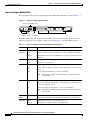
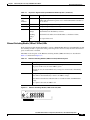
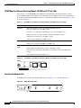
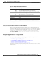
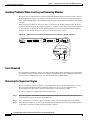
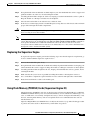
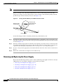
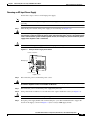
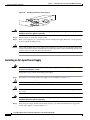
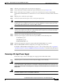
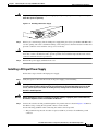
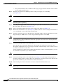
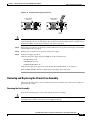
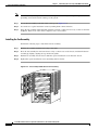
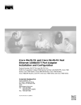
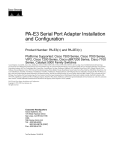
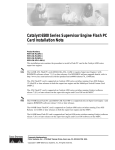
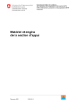
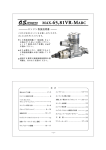
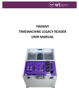
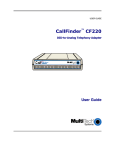
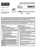
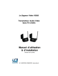
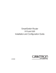
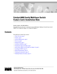
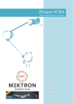
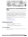
C H A P T E R
7
Maintaining the Cisco Catalyst 5500 Multiswitch
Router
This chapter contains recommended hardware maintenance procedures for the Cisco Catalyst 5500
Multiswitch Routers (MSRs), which provide an Ethernet backbone for connections between the
Cisco Signaling Link Terminals (SLTs), Cisco Media Gateway Controllers (MGCs), and Cisco Media
Gateways (MGWs). You can configure several virtual LANs (VLANs) on the Catalyst 5500s and the
route switch modules (RSMs) provide inter-VLAN routing when necessary. If your solution includes
two Catalyst 5500s, they are connected through an Inter-Switch Link (ISL) trunk, enabling them to share
VLAN data and provide ensured availability.
This chapter describes hardware maintenance; for information on upgrading and maintaining
Catalyst 5500 software, refer to the Cisco Media Gateway Controller Software Release 7 Installation
and Configuration Guide.
This chapter includes the following sections:
•
Checking Equipment Status, page 7-1
•
Replacing Hardware Components, page 7-5
Checking Equipment Status
Check the status of the Cisco Catalyst 5500, using the following methods:
•
Reading the Cisco Catalyst 5500 LEDs
•
Querying the status using the Catalyst command line interface (CLI)
•
Querying the system using CiscoWorks 2000 and Cisco WAN Manager (CWM)
Cisco Catalyst 5500 LEDs
LEDs of the Catalyst 5500 may vary, depending on which components are installed. The LEDs described
in this section are factory default.
Cisco MGC Software Release 7 Operations, Maintenance, and Troubleshooting Guide
OL-0542-06
7-1
Chapter 7
Maintaining the Cisco Catalyst 5500 Multiswitch Router
Checking Equipment Status
Supervisor Engine Module LEDs
The front panel of the supervisor engine III (product number WS X5530-E3) is shown in Figure 7-1.
Figure 7-1
Supervisor Engine III Front Panel
Console and Auxiliary ports
R
ES
SL
SL
O
O
T
T
0
1
ET
N
E
FA
2
AC
TIV
PS
1
PS
SUPERVISOR ENGINE I I I
Status
LEDs
PORT 1
CONSOLE
AUX
Switch
PCMCIA
Load
Reset
Switch
button Load display
PORT 2
MDIX
10/100Mbps
10/100Mbps
LINK
LINK
MDIX
10/100 FAST ETHERCHANNEL
PCMCIA slots
H10965
WS-U5531-FETX
100%
S
ST YS
AT TE
U M
S
WS-x5530
Uplink ports
The LEDs on the supervisor engine front panel indicate the status of the system, which includes the
supervisor engine, the power supplies, and the fan assembly. Table 7-1 describes LED operation.
Table 7-1
Supervisor Engine III and Uplink Module LED Descriptions
LED
State
Description
SYSTEM
STATUS
Green
Indicates that a series of self-tests and diagnostic tests has been passed.
Red
System is being booted or is faulty (fails a test or module is disabled).
Orange
Fan modules have failed or redundant power supply is installed, but not
turned on.
Green
The fan is operational.
Red
The fan is not operational.
Green
Power supply in left bay is operational.
Red
Power supply in left bay is not operational, switched off, or not receiving
power.
Off
Power supply in the left bay is off or not installed.
FAN
PS1
Note
PS2
The Catalyst 5500 power supply LED is red when no modules
are installed.
Green
The power supply in the right bay is operational.
Red
The power supply in the right bay is not operational, is switched off, or
is not receiving input power.
Off
The power supply in the right bay is off or is not installed.
Note
The Catalyst 5500 power supply LED is red when no modules
are installed.
SWITCH
LOAD
1–100%
If the switch is operational, the switch load display indicates (as an
approximate percentage) the current traffic load over the backplane.
ACTIVE
Green
The supervisor engine is operational and active.
Orange
The supervisor engine module is in standby mode.
Cisco MGC Software Release 7 Operations, Maintenance, and Troubleshooting Guide
7-2
OL-0542-06
Chapter 7
Maintaining the Cisco Catalyst 5500 Multiswitch Router
Checking Equipment Status
Table 7-1
Supervisor Engine III and Uplink Module LED Descriptions (continued)
LED
State
Description
SLOT 1
and
SLOT 0
On
Supervisor Engine III only: The Flash PC Card SLOT 1 and SLOT 0
LEDs light when their respective slot 1 and slot 0 Flash PC Card devices
are accessed.
100 Mbps
Green
The port is operating at 100 Mbps.
1000 Mbps Green
The port is operating at 1000 Mbps.
LINK
Green
The port is operational.
Orange
The link has been disabled by software.
Flashing
orange
The link is bad and has been disabled due to a hardware failure.
Off
No signal is detected.
Ethernet Switching Module (10BaseT 24 Port) LEDs
Each switching module (Prod # WS-X5013) contains a STATUS LED. When on, this LED indicates that
the switching module is operational and is powered up. It does not necessarily mean that the interface
ports are functional or enabled.
The LEDs on the faceplate of the Ethernet switching module (10BaseT 24 Port) are described in
Table 7-2 and shown in Figure 7-2.
Table 7-2
Ethernet Switching Module (10BaseT 24 Port) LED Descriptions
LED
Description
STATUS
The switch performs a series of self-tests and diagnostic tests.
If it passes all the tests, the status LED is green.
If it fails any test, the status LED is red (or orange for a minor fault or if manually
disabled).
Link
If the port is operational (a signal is detected), the LED is green.
If the link has been disabled by software, the LED is orange.
If the link is bad and has been disabled due to a hardware failure, the LED flashes
orange.
If no signal is detected, the LED is off.
Ethernet Switching Module (10BaseT 24 Port) LEDs
3
6
9
12
15
18
21
24
2
5
8
11
14
17
20
23
1
4
7
10
13
16
19
22
ETHERNET SWITCHING MODULE
H3043
ST
AT
US
Figure 7-2
Cisco MGC Software Release 7 Operations, Maintenance, and Troubleshooting Guide
OL-0542-06
7-3
Chapter 7
Maintaining the Cisco Catalyst 5500 Multiswitch Router
Checking Equipment Status
10/100 Mbps Fast Ethernet Switching Module (10/100BaseTX 12 Port) LEDs
The faceplate of each 10/100 Mbps Fast Ethernet Switching Module (Prod # WS-X5203) contains a
module STATUS LED, and two LEDs for each switching port. The LEDs provide status information for
the module and individual Fast Ethernet interface connections. The LEDs are described in Table 7-3 and
are shown in Figure 7-3.
Table 7-3
10/100 Mbps Fast Ethernet Switching Module (10/100BaseTX 12 Port) LEDs
LED
Description
STATUS
The switch performs a series of self-tests and diagnostic tests.
If it passes all the tests, the LED is green.
If it fails a test other than an individual port test fails, the LED is red.
During system boot or if the module is disabled, the LED is orange.
During self-test diagnostics, the LED is orange.
If the module is disabled, the LED is orange.
100 Mbps
If the port is operating at 100 Mbps, the LED is green.
If the port is operating at 10 Mbps, the LED is off.
LINK (bottom
LED)
If the port is operational (a signal is detected), the LED is green.
If the link has been disabled by software, the LED is orange.
If the link is bad and has been disabled due to a hardware failure, the LED flashes
orange.
If no signal is detected, the LED is off.
s
bp
M
0
10
NK
H5796
LI
LI
NK
10
0
ST
M
AT
bp
s
US
2
10/100 Mbps Fast Ethernet Switching Module (10/100BaseTX 12 Port) LEDs
1
Figure 7-3
10/100 Mbps FAST ETHERNET SWITCHING MODULE
Route Switch Module LEDs
The RSM (product number WS-X5302) LEDs, shown in Figure 7-4, are described in Table 7-3.
EL
X
AU
TX
C
H
AN
N
EL
TX
C
H
ET
ES
R
R
X
X
R
H10366
PC
M
IC
A
SL
O
T
0
SL
O
T
1
C
IA
PC
M
AN
N
T
EN C
AB PU
LE HA
L
D
S
AT
U
ST
ROUTE SWITCH MODULE
1
RSM (WS-X5302) LEDs
0
Figure 7-4
Cisco MGC Software Release 7 Operations, Maintenance, and Troubleshooting Guide
7-4
OL-0542-06
Chapter 7
Maintaining the Cisco Catalyst 5500 Multiswitch Router
Replacing Hardware Components
Table 7-4
RSM (WS-X5302) STATUS LED Descriptions
LED
State
Description
STATUS
Green
All the self-tests have been passed.
Red
A test other than an individual port test has been failed.
Orange
System boot, self-test diagnostics running, or the module is disabled.
On
Indicates normal RSM operation.
Off
The system detected a processor hardware failure.
On
Indicates IP microcode is loaded and the RSM is operational.
CPU HALT
ENABLED
PCMCIA
On
SLOTs 0 and 1
Indicates PCMCIA devices in slot 0 and 1 are being accessed by the
RSM.
TX1
Green
The port is transmitting a packet (LED is lit for approximately 50 ms).
2
Green
The port is receiving a packet (LED is lit for approximately 50 ms3)
RX
1. TX = transmit
2. RX = receive
3. ms = milliseconds
Using the Command Line Interface to Check Status
The Cisco Catalyst 5500 command line interface includes a series of commands that enable you to
determine if the MSR is functioning correctly or where problems have occurred. Relevant commands for
checking status include ping, traceroute, test snmp trap, and show. There are more than 100 show
commands, many of which can be used to check status. To learn how to find more information
concerning these and other commands, refer to the Command Reference Manual that came with the
Cisco Catalyst 5500 MSR.
Replacing Hardware Components
This section describes how to perform the following removal and replacement procedures for
Cisco Catalyst 5000 series field-replaceable units (FRUs):
•
Removing the Supervisor Engine, page 7-6
•
Using Flash Memory (PCMCIA) Cards (Supervisor Engine III), page 7-7
•
Removing and Replacing the Power Supply, page 7-8
•
Removing and Replacing the Chassis Fan Assembly, page 7-15
For instructions on installing and replacing switching modules, refer to the Catalyst 5000 Series Module
Installation Guide.
Cisco MGC Software Release 7 Operations, Maintenance, and Troubleshooting Guide
OL-0542-06
7-5
Chapter 7
Maintaining the Cisco Catalyst 5500 Multiswitch Router
Replacing Hardware Components
Avoiding Problems When Inserting and Removing Modules
The ejector levers on the supervisor engine and switching modules align and seat the module connectors
in the backplane (see Figure 7-5). Failure to use the ejector levers to insert the module can disrupt the
order in which the pins make contact with the backplane. Follow the installation and removal instructions
carefully.
When removing a module, use the ejector levers to ensure that the module connector pins disconnect
from the backplane properly. Any supervisor engine or switching module that is only partially connected
to the backplane can disrupt the system. Detailed instructions for removing and installing switching
modules are described in the Catalyst 5000 Series Module Installation Guide.
2
H9170
A4
1
M
DI
1
PO
R
X
1
A4
1
M
DI
X
SUPERVISOR ENGINE
T
LIN 10
K 0M
BP
S
1
PO
RT
M
BP
S
0
10
K
LIN
1%
CO
NS
OL
E
SW
IT
LO C
AD H
ET
ES
R
S
PS PS FA
1 2 N
AC
TIV
E
ST
AT
U
0%
Ejector Levers and Captive Installation Screws (Supervisor Engine II Shown)
10
Figure 7-5
Ejector lever
Captive
installation
screws
Tools Required
Use a flat-blade screwdriver to remove any filler (blank) modules and to tighten the captive installation
screws that secure the modules in their slots. When you handle modules, use an ESD-preventive wrist
strap or other grounding device to prevent electrostatic discharge (ESD) damage.
Removing the Supervisor Engine
Before you remove a supervisor engine, you should first upload the current configuration to a server.
This saves time when bringing the module back online. You can recover the configuration by
downloading it from the server to the nonvolatile memory of the supervisor engine.
To remove a supervisor engine, perform the following steps:
Step 1
If you do not plan to immediately reinstall the supervisor engine you are removing, disconnect any
network interface cables attached to the module ports.
Step 2
Use a screwdriver to loosen the captive installation screws at the left and right sides of the module.
Step 3
Grasp the left and right ejector levers and simultaneously pull the left lever to the left and the right lever
to the right to release the module from the backplane connector.
Cisco MGC Software Release 7 Operations, Maintenance, and Troubleshooting Guide
7-6
OL-0542-06
Chapter 7
Maintaining the Cisco Catalyst 5500 Multiswitch Router
Replacing Hardware Components
Step 4
Grasp the handle of the module with one hand and place your other hand under the carrier to support and
guide the module out of the slot. Avoid touching the module.
Step 5
Carefully pull the module straight out of the slot, keeping your other hand under the carrier to guide it.
Keep the module at a 90-degree orientation to the backplane.
Step 6
Place the removed module on an antistatic mat or antistatic foam.
Step 7
If the slot is to remain empty, install a module filler plate to keep dust out of the chassis and to maintain
proper airflow through the module compartment.
Caution
Always install a switching module filler plate in empty switching module slots to maintain the proper
flow of cooling air across the modules.
Note
When you remove and replace the supervisor engine, the system provides status messages on the console
screen. The messages are for information only. Enter the show system and show module commands to
view specific information. For additional information, refer to the Catalyst 5000 Series Software
Configuration Guide and the Catalyst 5000 Series Command Reference. Also, refer to the Preface for a
description of Cisco Connection Online (CCO).
Replacing the Supervisor Engine
To replace the supervisor engine, perform the following steps. Note that the supervisor engine must go
in slot 1 and the redundant supervisor engine in slot 2.
Step 1
Remove the module filler plate, if any.
Step 2
Grasp the handle of the module with one hand and carefully align the module with the slot, keeping your
other hand under the carrier to support it. Keep the module at a 90-degree orientation to the backplane.
Step 3
Carefully push the module straight into the slot, keeping one hand under the carrier to guide it. Avoid
touching the module.
Step 4
Make sure that the ejector levers are pushed in, holding the module to the backplane connector.
Step 5
Use a screwdriver to tighten the captive installation screws at the left and right sides of the module.
Step 6
Reattach network interface cables to the module ports.
Using Flash Memory (PCMCIA) Cards (Supervisor Engine III)
The Flash memory (PCMCIA) card slots on the front panel of Supervisor Engine III are for additional
PCMCIA-based Flash memory. You can use this Flash memory to store and run Cisco IOS images, or to
serve as an I/O device. Occasionally, it might be necessary to remove and replace Flash memory cards;
however, removing Flash memory cards is not required and is not recommended after the cards are
installed in the slots.
Supervisor Engine III has two PCMCIA slots: slot 0 (bottom) and slot 1 (top). The following procedure
is generic and can be used for a Flash memory card in either slot position.
Cisco MGC Software Release 7 Operations, Maintenance, and Troubleshooting Guide
OL-0542-06
7-7
Chapter 7
Maintaining the Cisco Catalyst 5500 Multiswitch Router
Replacing Hardware Components
Note
You can insert and remove the Flash memory card with the power on.
Before you install a card, verify that the Flash memory card is set with write protection off. The
write-protect switch is located on the front edge of the card when oriented with the printing right side
up and the edge connector end away from you. (See Figure 7-6.)
Figure 7-6
Locating the Flash Memory Card Write-Protection Switch
Flash PC card
shown with write
protection off
H2352
Flash PC card
write protection
Flash PC card
Use the following procedure for installing and removing a Flash memory card:
Step 1
Face the front panel of the switch and hold the Flash memory card with the connector end of the card
toward the slot. The connector end of the card is opposite the end with the write-protection switch, which
is shown in Figure 7-6.
Step 2
Insert the card into the appropriate slot until the card completely seats in the connector at the back of the
slot and the eject button pops out toward you. Note that the card does not insert all the way into the slot;
a portion of the card remains outside the slot. Do not attempt to force the card past this point.
Step 3
To eject a card, press the appropriate ejector button until the card is free of the connector at the back of
the slot.
Step 4
Remove the card from the slot and place it in an antistatic bag.
Removing and Replacing the Power Supply
This section describes the procedure you use to remove and install power supplies for the Cisco Catalyst
5500 switches. Use a flat-blade screwdriver to perform these procedures.
•
Removing an AC-Input Power Supply, page 7-9
•
Installing an AC-Input Power Supply, page 7-10
•
Removing a DC-Input Power Supply, page 7-11
•
Installing a DC-Input Power Supply, page 7-13
Cisco MGC Software Release 7 Operations, Maintenance, and Troubleshooting Guide
7-8
OL-0542-06
Chapter 7
Maintaining the Cisco Catalyst 5500 Multiswitch Router
Replacing Hardware Components
Removing an AC-Input Power Supply
Follow these steps to remove an AC-input power supply:
Note
Step 1
Warning
Caution
In systems with redundant power supplies, the faulty supply can be replaced while the system is
operating.
Turn off the power switch on the power supply you are removing (see Figure 7-7).
Do not touch the power supply when the power cord is connected. For systems with a power switch,
line voltages are present within the power supply even when the power switch is off and the power
cord is connected. For systems without a power switch, line voltages are present within the power
supply when the power cord is connected.
Failure to turn off the power supply could result in equipment damage.
Figure 7-7
AC-Input Power Supply Front Panels
Power connection
AC
OK
FAN
OK
OUTPUT
FAIL
Metal prongs
H11764
o
Power switch
Captive screw
Step 2
Warning
Disconnect the power cord from the power source.
Before working on a chassis or working near power supplies, unplug the power cord on AC units;
disconnect the power at the circuit breaker on DC units.
Step 3
Disconnect the power cord from the power supply being removed.
Step 4
Using a flat-blade screwdriver, loosen and remove the captive installation screws (see Figure 7-7).
Caution
Step 5
Use both hands to install and remove power supplies.
Grasp the power supply handle with one hand and place your other hand underneath to support the
bottom of the supply, as shown in Figure 7-8 (Cisco Catalyst 5000 supply shown).
Cisco MGC Software Release 7 Operations, Maintenance, and Troubleshooting Guide
OL-0542-06
7-9
Chapter 7
Maintaining the Cisco Catalyst 5500 Multiswitch Router
Replacing Hardware Components
Handling an AC-Input Power Supply
POWER
100-127/200-240 V~
8.0/4.0 A
60/50 Hz
Warning
H2751
Figure 7-8
Keep your hands and fingers out of the power supply bays. High current is present on the power
backplane when the system is operating.
Step 6
Pull the supply out of the bay and put it aside.
Step 7
If the power supply bay is to remain empty, install a blank power supply filler plate over the opening;
secure it with the mounting screws.
Caution
Always install a filler plate over an empty power supply bay, not only to protect the inner chassis and
connectors from dust or other contamination, but to prevent possible contact with the high current levels
of those connectors when the chassis is powered on.
Installing an AC-Input Power Supply
Warning
Before installing a Cisco Catalyst 5500 AC-input power supply, read the warning in the “Removing an
AC-Input Power Supply” section.
Follow these steps to install an AC-input power supply:
Step 1
Turn off the power switch on the power supply you are installing (see Figure 7-9).
Caution
Failure to turn off the power supply could result in equipment damage.
Caution
Use both hands to install and remove power supplies. The Cisco Catalyst 5500 power supply weighs 22
lb. (9.9 kg).
Warning
Keep your hands and fingers out of the power supply bays. High current is present on the power
backplane when the system is operating.
Step 2
Grasp the power supply handle with one hand and place your other hand underneath to support the
bottom of the supply, as shown in Figure 7-11.
Cisco MGC Software Release 7 Operations, Maintenance, and Troubleshooting Guide
7-10
OL-0542-06
Chapter 7
Maintaining the Cisco Catalyst 5500 Multiswitch Router
Replacing Hardware Components
Step 3
Slide the power supply all the way into the power supply bay.
Step 4
Using a flat-blade screwdriver, tighten the captive installation screws (see Figure 7-10).
Step 5
Before connecting the power supply to a power source, ensure that all site power and grounding
requirements described in the Cisco Media Gateway Controller Hardware Installation Guide have been
met.
Step 6
Plug the power cord into the power supply.
Step 7
Connect the other end of the power cord to an AC-power input source.
Note
Each AC-input power supply operating at 120 VAC requires a dedicated 20A service and 20A plug and
receptacle. It is not acceptable to power the Cisco Catalyst 5500 from a 15A line cord because of the
safety ratings under which the Cisco Catalyst 5500 is certified.
Caution
In a system with dual power supplies, connect each power supply to a separate input source. In case of
a power source failure, the second source will probably still be available and can maintain maximum
overcurrent protection for each power connection.
Step 8
Turn the power switch to the ON position on the power supply.
Step 9
Verify that power supply operation and the front panel LEDs are in the following states:
AC OK LED is green.
FAN OK LED is green.
OUTPUT FAIL LED is off.
Step 10
Verify that the appropriate supervisor engine module PS1 and PS2 LEDs are on (green).
Step 11
Enter the show system command to display the power supply and system status.
If the LEDs or show system command indicate a power or other system problem, refer to Appendix C,
“Troubleshooting Cisco Catalyst 5500 Multiswitch Routers Signaling,” for troubleshooting information.
Removing a DC-Input Power Supply
Follow these steps to remove a DC-input power supply (product number WS-C5568):
Step 1
Verify that power is off to the DC circuit on the power supply you are removing.
Warning
Before performing the following procedures, ensure that power is removed from the DC circuit. To
ensure that all power is OFF, locate the circuit breaker on the panel board that services the DC circuit,
switch the circuit breaker to the OFF position, and tape the switch handle of the circuit breaker in the
OFF position.
Warning
Before working on a chassis or working near power supplies, unplug the power cord on AC units;
disconnect the power at the circuit breaker on DC units.
Cisco MGC Software Release 7 Operations, Maintenance, and Troubleshooting Guide
OL-0542-06
7-11
Chapter 7
Maintaining the Cisco Catalyst 5500 Multiswitch Router
Replacing Hardware Components
Step 2
Turn the power switch to the OFF (0) position on the power supply you are removing (see Figure 7-9).
Step 3
Remove the two screws securing the terminal block cover and slide the cover straight off the terminal
block (see Figure 7-9).
Figure 7-9
DC-Input Power Supply Front Panels
Remove
DC
FAN OUTPUT
OK
OK
FAIL
Terminal
block
cover
Remove
I
0
H8767
Power
switch
Captive screw
Step 4
Disconnect the DC-input wires from the terminal block. Disconnect the ground wire last.
Step 5
Disconnect the central office (CO) ground from the CO ground connector (Figure 7-10).
Figure 7-10 DC-Input Power Supply CO Ground
N
FA
2
PS
1
PS
SWITCH/PROCESSOR
ET
S
RE
TX
T2
SLO
RX
T1
K
LIN
SLO
t
Ene
IA
MC
PC
CT
EJE
o
28649
o
CO ground
connector
location
Step 6
Caution
Step 7
Loosen and remove the captive screws on the power supply (see Figure 7-9).
Use both hands to remove and install power supplies.
Grasp the power supply handle with one hand and place your other hand underneath as you slowly pull
the power supply out of the bay (see Figure 7-11).
Cisco MGC Software Release 7 Operations, Maintenance, and Troubleshooting Guide
7-12
OL-0542-06
Chapter 7
Maintaining the Cisco Catalyst 5500 Multiswitch Router
Replacing Hardware Components
Warning
Keep hands and fingers out of the power supply bays. High voltage is present on the power backplane
when the system is operating.
H7805
Figure 7-11 Handling a DC Power Supply
INPUT
48/60
14.0/8.0 A
Step 8
If the bay is to remain empty, install a blank power supply filler plate (Cisco part number 700-00177-01)
over the opening and secure it with the mounting screws. This protects the inner chassis from dust and
prevents accidental contact with live voltage at rear of the bay.
Caution
Always install a filler plate over an empty power supply bay to protect the inner chassis and connectors
from dust or other contamination and to prevent possible contact with the high current levels of those
connectors when the chassis is powered on.
Step 9
Reinstall the power supply terminal block cover.
Installing a DC-Input Power Supply
Follow these steps to install a DC-input power supply:
Step 1
Verify that power is off to the DC circuit on the power supply you are installing.
Warning
Before performing any of the following procedures, ensure that power is removed from the DC circuit.
To ensure that all power is OFF, locate the circuit breaker on the panel board that services the DC
circuit, switch the circuit breaker to the OFF position, and tape the switch handle of the circuit
breaker in the OFF position.
Warning
Before working on a chassis or working near power supplies, unplug the power cord on AC units;
disconnect the power at the circuit breaker on DC units.
Step 2
Connect the switch to the CO ground through the CO ground connector shown in Figure 7-10. Remove
the adhesive strip covering the CO ground connector on the switch.
Use the following guidelines when connecting the switch to the CO ground:
•
The ground wire lug must be less than or equal to 0.320 in. (8.1 mm) to fit within the ground
connector.
Cisco MGC Software Release 7 Operations, Maintenance, and Troubleshooting Guide
OL-0542-06
7-13
Chapter 7
Maintaining the Cisco Catalyst 5500 Multiswitch Router
Replacing Hardware Components
•
Step 3
Caution
The ground wire must be 10 to 12 AWG. Use the larger gauge ground wire when the switch is further
away from the ground location.
Turn the power switch to the OFF (0) position on the power supply you are installing
(see Figure 7-10).
Use both hands to remove and install power supplies.
Warning
Keep hands and fingers out of the power supply bays. High voltage is present on the power backplane
when the system is operating.
Step 4
Grasp the power supply handle with one hand and place your other hand underneath as you slowly insert
the power supply into the bay (see Figure 7-11).
Step 5
Using a screwdriver, tighten the captive screws on the power supply (see Figure 7-9).
Step 6
Remove the terminal block cover (see Figure 7-9). Remove the two screws securing the terminal block
cover and slide the cover straight off the terminal block.
Step 7
Attach the appropriate lugs to the DC-input wires. Maximum width of the lugs is 0.300 inch (7.6 mm).
Suggested lugs are AMP 322985 or 52941. Suggested DC-input wires are 10 AWG.
Caution
When stranded wiring is required, use approved wiring terminations, such as closed-loop or spade-type
with upturned lugs. These terminations must be the appropriate size for the wires and clamp both the
insulation and conductor.
Step 8
Connect the DC-input wires to the terminal block.
If not already done, route the DC-input power cable through the conduit from your power source,
through the conduit bracket on the power supply, and make a sufficient length of wire available to attach
to the three terminal block connections.
Attach and tighten the conduit to the conduit bracket. How this conduit is attached depends on your site;
its attachment is beyond the scope of this document.
Caution
Connect the ground wire first.
Step 9
Connect the DC-input wires to the terminal block (see Figure 7-12). The proper wiring sequence is
ground to ground, positive to positive (line to L), and negative to negative (neutral to N). Note that the
ground wire should always be connected first and disconnected last.
Step 10
After ensuring that all wire connections are secure, reinstall the terminal block cover.
Caution
To prevent a short-circuit or shock hazard after wiring the DC-input power supply, reinstall the terminal
block cover.
Cisco MGC Software Release 7 Operations, Maintenance, and Troubleshooting Guide
7-14
OL-0542-06
Chapter 7
Maintaining the Cisco Catalyst 5500 Multiswitch Router
Replacing Hardware Components
Figure 7-12 DC-Input Power Supply Connectors
Terminal block
connectors
Terminal block
connectors
INPUT
48/60
14.0/8.0 A
H9325
INPUT
48/60
14.0/8.0 A
Power
switch
Caution
In a system with dual power supplies, use the modular power cord to connect each power supply to a
separate input line. In case of a line failure, the second source will most likely still be available and can
maintain maximum overcurrent protection for each power connection.
Step 11
Remove the tape from the circuit breaker switch handle and restore power by moving the circuit breaker
switch handle to the on position.
Step 12
Turn the power switch to the on position on the power supply.
Step 13
Verify power supply operation.
Verify that the power supply front panel LEDs are in the following states:
DC OK LED is green.
FAN OK LED is green.
OUTPUT FAIL LED is off.
Verify that the appropriate supervisor engine module PS1 and PS2 LEDs are on and green.
Enter the show system command to display the power supply and system status.
Removing and Replacing the Chassis Fan Assembly
This section describes how to remove and install chassis fan assemblies. Use a flat-blade screwdriver to
perform this procedure.
Removing the Fan Assembly
Perform the following steps to remove the existing chassis fan assembly:
Caution
Never operate the system if the fan assembly is removed or if it is not functioning properly. An
overtemperature condition can result in severe equipment damage.
Cisco MGC Software Release 7 Operations, Maintenance, and Troubleshooting Guide
OL-0542-06
7-15
Chapter 7
Maintaining the Cisco Catalyst 5500 Multiswitch Router
Replacing Hardware Components
Note
The fan assembly is designed to be removed and replaced while the system is operating without
presenting an electrical hazard or damage to the system.
Step 1
Locate the fan assembly to the left of the card cage (see Figure 7-13).
Step 2
Loosen the two captive installation screws by turning them counterclockwise.
Step 3
Grasp the fan assembly with both hands and pull it outward, joggling it if necessary to unseat it from the
backplane. Pull it clear of the chassis and place it in a safe location.
Installing the Fan Assembly
Perform the following steps to install the new fan assembly:
Step 1
Hold the fan assembly with the fans facing to the right.
Step 2
Place the fan assembly into the front chassis cavity so that it rests on the chassis, and then lift the fan
assembly up slightly, aligning the top and bottom guides.
Step 3
Push the fan assembly into the chassis until the captive installation screws meet the chassis.
Step 4
Tighten the captive installation screws by turning them clockwise.
1
LIN 100
K
Mb
ps
PO
RT
2
PO
RT
MII
MD
IX
MII
1
H10647
MII
MD
IX
MII
LIN 100
K
Mb
ps
PO
RT
2
PO
RT
MD
IX
SUPERVISOR ENGINE
LIN 100
K
Mb
ps
FA
N
PS PS
2
1
SY
ST ST
AT EM
US
MD
IX
SUPERVISOR ENGINE
LIN 100
K
Mb
ps
1%
SW
ITC
LO H
G
CO
NS
OL
E
1%
SW
ITC
LO H
G
CO
NS
OL
E
100
%
FA
N
AC
TIV
E
RE
SE
T
100
%
SY
ST ST
AT EM
US
PS PS
2
1
AC
TIV
E
RE
SE
T
Figure 7-13 Cisco Catalyst 5500 Chassis Fan Assembly
Cisco MGC Software Release 7 Operations, Maintenance, and Troubleshooting Guide
7-16
OL-0542-06
Chapter 7
Maintaining the Cisco Catalyst 5500 Multiswitch Router
Replacing Hardware Components
Checking the Installation
Perform the following steps to verify that the new fan assembly is installed correctly:
Step 1
Listen for the fans; you should immediately hear them operating. If you do not hear them, ensure that
the fan assembly is completely inserted in the chassis and that the faceplate is flush with the switch back
panel.
Step 2
If after several attempts the fans do not operate, or if you experience trouble with the installation (for
instance, if the captive installation screws do not align with the chassis holes), contact the Cisco
Technical Assistance Center (TAC) for assistance. Refer to the “Obtaining Technical Assistance” section
on page xviii for information on contacting the Cisco TAC.
Cisco MGC Software Release 7 Operations, Maintenance, and Troubleshooting Guide
OL-0542-06
7-17
Chapter 7
Maintaining the Cisco Catalyst 5500 Multiswitch Router
Replacing Hardware Components
Cisco MGC Software Release 7 Operations, Maintenance, and Troubleshooting Guide
7-18
OL-0542-06