1
Cisco ONS 15310-MA SDH Reference
Manual
Product and Documentation Release 9.1 and Release 9.2
August 2012
Americas Headquarters
Cisco Systems, Inc.
170 West Tasman Drive
San Jose, CA 95134-1706
USA
http://www.cisco.com
Tel: 408 526-4000
800 553-NETS (6387)
Fax: 408 527-0883
Text Part Number: 78-19417-01
THE SPECIFICATIONS AND INFORMATION REGARDING THE PRODUCTS IN THIS MANUAL ARE SUBJECT TO CHANGE WITHOUT NOTICE. ALL
STATEMENTS, INFORMATION, AND RECOMMENDATIONS IN THIS MANUAL ARE BELIEVED TO BE ACCURATE BUT ARE PRESENTED WITHOUT
WARRANTY OF ANY KIND, EXPRESS OR IMPLIED. USERS MUST TAKE FULL RESPONSIBILITY FOR THEIR APPLICATION OF ANY PRODUCTS.
THE SOFTWARE LICENSE AND LIMITED WARRANTY FOR THE ACCOMPANYING PRODUCT ARE SET FORTH IN THE INFORMATION PACKET THAT
SHIPPED WITH THE PRODUCT AND ARE INCORPORATED HEREIN BY THIS REFERENCE. IF YOU ARE UNABLE TO LOCATE THE SOFTWARE LICENSE
OR LIMITED WARRANTY, CONTACT YOUR CISCO REPRESENTATIVE FOR A COPY.
The following information is for FCC compliance of Class A devices: This equipment has been tested and found to comply with the limits for a Class A digital device, pursuant
to part 15 of the FCC rules. These limits are designed to provide reasonable protection against harmful interference when the equipment is operated in a commercial
environment. This equipment generates, uses, and can radiate radio-frequency energy and, if not installed and used in accordance with the instruction manual, may cause
harmful interference to radio communications. Operation of this equipment in a residential area is likely to cause harmful interference, in which case users will be required
to correct the interference at their own expense.
The following information is for FCC compliance of Class B devices: The equipment described in this manual generates and may radiate radio-frequency energy. If it is not
installed in accordance with Cisco’s installation instructions, it may cause interference with radio and television reception. This equipment has been tested and found to
comply with the limits for a Class B digital device in accordance with the specifications in part 15 of the FCC rules. These specifications are designed to provide reasonable
protection against such interference in a residential installation. However, there is no guarantee that interference will not occur in a particular installation.
Modifying the equipment without Cisco’s written authorization may result in the equipment no longer complying with FCC requirements for Class A or Class B digital
devices. In that event, your right to use the equipment may be limited by FCC regulations, and you may be required to correct any interference to radio or television
communications at your own expense.
You can determine whether your equipment is causing interference by turning it off. If the interference stops, it was probably caused by the Cisco equipment or one of its
peripheral devices. If the equipment causes interference to radio or television reception, try to correct the interference by using one or more of the following measures:
• Turn the television or radio antenna until the interference stops.
• Move the equipment to one side or the other of the television or radio.
• Move the equipment farther away from the television or radio.
• Plug the equipment into an outlet that is on a different circuit from the television or radio. (That is, make certain the equipment and the television or radio are on circuits
controlled by different circuit breakers or fuses.)
Modifications to this product not authorized by Cisco Systems, Inc. could void the FCC approval and negate your authority to operate the product.
The Cisco implementation of TCP header compression is an adaptation of a program developed by the University of California, Berkeley (UCB) as part of UCB’s public
domain version of the UNIX operating system. All rights reserved. Copyright © 1981, Regents of the University of California.
NOTWITHSTANDING ANY OTHER WARRANTY HEREIN, ALL DOCUMENT FILES AND SOFTWARE OF THESE SUPPLIERS ARE PROVIDED “AS IS” WITH
ALL FAULTS. CISCO AND THE ABOVE-NAMED SUPPLIERS DISCLAIM ALL WARRANTIES, EXPRESSED OR IMPLIED, INCLUDING, WITHOUT
LIMITATION, THOSE OF MERCHANTABILITY, FITNESS FOR A PARTICULAR PURPOSE AND NONINFRINGEMENT OR ARISING FROM A COURSE OF
DEALING, USAGE, OR TRADE PRACTICE.
IN NO EVENT SHALL CISCO OR ITS SUPPLIERS BE LIABLE FOR ANY INDIRECT, SPECIAL, CONSEQUENTIAL, OR INCIDENTAL DAMAGES, INCLUDING,
WITHOUT LIMITATION, LOST PROFITS OR LOSS OR DAMAGE TO DATA ARISING OUT OF THE USE OR INABILITY TO USE THIS MANUAL, EVEN IF CISCO
OR ITS SUPPLIERS HAVE BEEN ADVISED OF THE POSSIBILITY OF SUCH DAMAGES.
Cisco and the Cisco logo are trademarks or registered trademarks of Cisco and/or its affiliates in the U.S. and other countries. To view a list of Cisco trademarks, go to this
URL: www.cisco.com/go/trademarks. Third-party trademarks mentioned are the property of their respective owners. The use of the word partner does not imply a partnership
relationship between Cisco and any other company. (1110R)
Any Internet Protocol (IP) addresses used in this document are not intended to be actual addresses. Any examples, command display output, and figures included in the
document are shown for illustrative purposes only. Any use of actual IP addresses in illustrative content is unintentional and coincidental.
Cisco ONS 15310-MA SDH Reference Manual, Release 9.1 and 9.2
Copyright © 2008–2012 Cisco Systems, Inc. All rights reserved.
CONTENTS
Preface
xxi
Revision History
xxi
Document Objectives
Audience
xxii
xxii
Related Documentation
xxii
Document Conventions
xxiii
Obtaining Optical Networking Information xxix
Where to Find Safety and Warning Information xxix
Cisco Optical Networking Product Documentation CD-ROM
Obtaining Documentation and Submitting a Service Request
CHAPTER
1
Cisco ONS 15310-MA SDH Shelf Assembly Hardware
1.1 Installation Overview
xxix
xxix
1-1
1-1
1.2 Rack Installation 1-2
1.2.1 Mounting Brackets 1-3
1.2.2 Mounting a Single Node 1-4
1.2.3 Mounting Multiple Nodes 1-5
1.3 Electrical Interface Assemblies
1.4 Front Door
1-6
1.5 Rear Cover
1-7
1.6 Power and Ground Description
1.7 Shelf Temperature
1-5
1-7
1-10
1.8 Cable Description and Installation 1-10
1.8.1 Cabling Types 1-10
1.8.2 Fiber Cable Installation 1-13
1.8.3 Coaxial Cable Installation 1-14
1.8.4 E1 Cable Installation 1-15
1.8.5 Alarm Cable Installation 1-18
1.8.6 BITS Cable Installation 1-20
1.8.7 UDC Cable Installation 1-20
1.9 Cable Routing and Management 1-21
1.9.1 Standard Cable Management Bracket
1.9.2 Extended Cable Management Bracket
1-21
1-22
Cisco ONS 15310-MA SDH Reference Manual, Release 9.1 and Release 9.2
78-19417-01
iii
Contents
1.10 Fan-Tray Assembly 1-23
1.10.1 Fan Speed and Power Requirements
1.10.2 Fan Failure 1-24
1.10.3 Air Filter 1-24
1.10.4 Orderwire 1-24
1.11 Cards and Slots
CHAPTER
2
Card Reference
1-24
1-26
2-1
2.1 Card Summary and Compatibility
2.1.1 Card Summary 2-2
2.1.2 Card Compatibility 2-3
2-1
2.2 15310E-CTX-K9 Card 2-4
2.2.1 System Cross-Connect 2-5
2.2.2 15310E-CTX-K9 Card Side Switches 2-5
2.2.3 15310E-CTX-K9 Optical Interfaces 2-5
2.2.4 15310E-CTX-K9 Card-Level Indicators 2-5
2.2.5 15310E-CTX-K9 Port-Level Indicators 2-6
2.3 CE-100T-8 Card 2-6
2.3.1 CE-100T-8 Card-Level Indicators 2-8
2.3.2 CE-100T-8 Port-Level Indicators 2-8
2.4 CE-MR-6 Card 2-9
2.4.1 CE-MR-6 Card-Level Indicators 2-12
2.4.2 CE-MR-6 Port-Level Indicators 2-12
2.5 ML-100T-8 Card 2-12
2.5.1 ML-100T-8 Card Description 2-13
2.5.2 ML-Series Cisco IOS CLI Console Port 2-13
2.5.3 ML-100T-8 Card-Level Indicators 2-15
2.5.4 ML-100T-8 Port-Level Indicators 2-15
2.6 E1_21_E3_DS3_3 and E1_63_E3_DS3_3 Cards 2-16
2.6.1 E1_21_E3_DS3_3 and E1_63_E3_DS3_3 Card-Level Indicators
2.7 Filler Cards
2-17
2-18
2.8 SFP Modules 2-19
2.8.1 Compatibility by Card 2-20
2.8.2 SFP Description 2-21
2.8.3 PPM Provisioning 2-22
CHAPTER
3
Card Protection
3.1 Overview
3-1
3-1
Cisco ONS 15310-MA SDH Reference Manual, Release 9.1 and Release 9.2
iv
78-19417-01
Contents
3.2 ONS 15310-MA SDH Card and Port Protection 3-1
3.2.1 1:1 Electrical Card Protection 3-2
3.2.2 .LMSP Optical Port Protection 3-4
3.2.3 .15310E-CTX-K9 Card Equipment Protection 3-4
3.3 Automatic Protection Switching
3-5
3.4 External Switching Commands
CHAPTER
4
3-5
Cisco Transport Controller Operation
4-1
4.1 CTC Software Delivery Methods 4-1
4.1.1 CTC Software Installed on the 15310E-CTX-K9 Card 4-1
4.1.2 CTC Software Installed on the PC or UNIX Workstation 4-2
4.2 CTC Installation Overview
4-3
4.3 PC, UNIX and Mac Workstation Requirements
4.4 ONS 15310-MA SDH Connection
4.5 CTC Login
4-3
4-5
4-6
4.6 CTC Window 4-7
4.6.1 Node View 4-8
4.6.1.1 CTC Card Colors 4-8
4.6.1.2 Node View Card Shortcuts
4.6.1.3 Node View Tabs 4-10
4.6.2 Network View 4-11
4.6.2.1 CTC Node Colors 4-12
4.6.2.2 Network View Tabs 4-12
4.6.2.3 DCC Links 4-13
4.6.2.4 Link Consolidation 4-13
4.6.3 Card View 4-14
4.6.4 Print and Export CTC Data 4-15
4-10
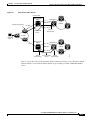
4.7 Using the CTC Launcher Application to Manage Multiple ONS Nodes
4.8 Common Control Card Reset
4.9 Traffic Card Reset
4-19
4.10 Database Backup
4-20
4.11 Software Revert
CHAPTER
5
Security
4-16
4-19
4-20
5-1
5.1 Users IDs and Security Levels
5-1
5.2 User Privileges and Policies 5-2
5.2.1 User Privileges by CTC Action
5.2.2 Security Policies 5-5
5-2
Cisco ONS 15310-MA SDH Reference Manual, Release 9.1 and Release 9.2
78-19417-01
v
Contents
5.2.2.1 Superuser Privileges for Provisioning Users 5-6
5.2.2.2 Idle User Timeout 5-6
5.2.2.3 User Password, Login, and Access Policies 5-6
5.3 Audit Trail 5-7
5.3.1 Audit Trail Log Entries 5-7
5.3.2 Audit Trail Capacities 5-8
5.4 RADIUS Security 5-8
5.4.1 RADIUS Authentication
5.4.2 Shared Secrets 5-8
CHAPTER
6
Timing
5-8
6-1
6.1 Timing Parameters
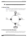
6.2 Network Timing
6-1
6-2
6.3 Synchronization Status Messaging
CHAPTER
7
Circuits and Tunnels
7.1 Overview
6-2
7-1
7-1
7.2 Circuit Properties 7-2
7.2.1 Circuit Status 7-3
7.2.2 Circuit States 7-4
7.2.3 Circuit Protection Types 7-5
7.2.4 Circuit Information in the Edit Circuits Window
7.3 VC-12 Bandwidth
7-6
7-8
7.4 VC Low-order Path Tunnels and Aggregation Points
7.5 DCC Tunnels 7-8
7.5.1 Traditional DCC Tunnels
7.5.2 IP-Encapsulated Tunnels
7-8
7-9
7-9
7.6 Subnetwork Connection Protection Circuits 7-9
7.6.1 Open-Ended Subnetwork Connection Protection Circuits 7-10
7.6.2 Go-and-Return Subnetwork Connection Protection Routing 7-10
7.7 Virtual Concatenated Circuits 7-11
7.7.1 VCAT Circuit States 7-11
7.7.2 VCAT Member Routing 7-12
7.7.3 Link Capacity Adjustment 7-13
7.7.4 VCAT Circuit Size 7-14
7.7.5 Open-Ended VCAT 7-15
7.7.5.1 Open-Ended VCAT Protection
7.8 Section and Path Trace
7-16
7-17
Cisco ONS 15310-MA SDH Reference Manual, Release 9.1 and Release 9.2
vi
78-19417-01
Contents
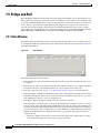
7.9 Bridge and Roll 7-18
7.9.1 Rolls Window 7-18
7.9.2 Roll Status 7-19
7.9.3 Single and Dual Rolls 7-20
7.9.4 Two-Circuit Bridge and Roll 7-22
7.9.5 Protected Circuits 7-22
7.10 Merged Circuits
7-22
7.11 Reconfigured Circuits
7-23
7.12 Server Trails 7-23
7.12.1 Server Trail Protection Types 7-24
7.12.2 VCAT Circuit Routing over Server Trails 7-24
7.12.2.1 Shared Resource Link Group 7-25
CHAPTER
8
Management Network Connectivity
8.1 IP Networking Overview
8-1
8-2
8.2 IP Addressing Scenarios 8-2
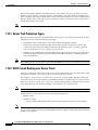
8.2.1 Scenario 1: CTC and ONS 15310-MA SDH Nodes on the Same Subnet 8-3
8.2.2 Scenario 2: CTC and ONS 15310-MA SDH Nodes Connected to a Router 8-3
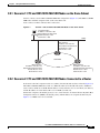
8.2.3 Scenario 3: Using Proxy ARP to Enable an ONS 15310-MA SDH Gateway 8-4
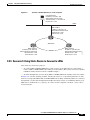
8.2.4 Scenario 4: Default Gateway on CTC Computer 8-6
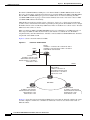
8.2.5 Scenario 5: Using Static Routes to Connect to LANs 8-7
8.2.6 Scenario 6: Using OSPF 8-9
8.2.7 Scenario 7: Provisioning the ONS 15310-MA SDH Proxy Server 8-11
8.3 Routing Table
8-16
8.4 External Firewalls
8.5 Open GNE
8-18
8-20
8.6 TCP/IP and OSI Networking 8-22
8.6.1 Point-to-Point Protocol 8-23
8.6.2 Link Access Protocol on the D Channel 8-24
8.6.3 OSI Connectionless Network Service 8-24
8.6.4 OSI Routing 8-27
8.6.4.1 End System-to-Intermediate System Protocol 8-28
8.6.4.2 Intermediate System-to-Intermediate System Protocol
8.6.5 TARP 8-29
8.6.5.1 TARP Processing 8-30
8.6.5.2 TARP Loop Detection Buffer 8-31
8.6.5.3 Manual TARP Adjacencies 8-32
8.6.5.4 Manual TID to NSAP Provisioning 8-32
8.6.6 OSI Virtual Routers 8-32
8-28
Cisco ONS 15310-MA SDH Reference Manual, Release 9.1 and Release 9.2
78-19417-01
vii
Contents
8.6.7 IP-over-CLNS Tunnels 8-33
8.6.7.1 Provisioning IP-over-CLNS Tunnels 8-34
8.6.7.2 IP Over CLNS Tunnel Scenario 1: ONS Node to Other Vendor GNE 8-34
8.6.7.3 IP-Over-CLNS Tunnel Scenario 2: ONS Node to Router 8-35
8.6.7.4 IP-Over-CLNS Tunnel Scenario 3: ONS Node to Router Across an OSI DCN
8.6.8 Provisioning OSI in CTC 8-39
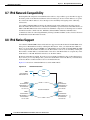
8.7 IPv6 Network Compatibility
8-37
8-40
8.8 IPv6 Native Support 8-40
8.8.1 IPv6 Enabled Mode 8-41
8.8.2 IPv6 Disabled Mode 8-41
8.8.3 IPv6 in Non-secure Mode 8-42
8.8.4 IPv6 in Secure Mode 8-42
8.8.5 IPv6 Limitations 8-42
8.9 FTP Support for ENE Database Backup
CHAPTER
SDH Topologies and Upgrades
9
8-42
9-1
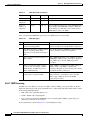
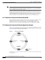
9.1 Subnetwork Connection Protection Configurations 9-1
9.1.1 Subnetwork Connection Protection Bandwidth 9-2
9.1.2 Subnetwork Connection Protection Application Example
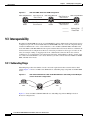
9.2 Terminal Point-to-Point and Linear ADM Configurations
9-2
9-3
9.3 Interoperability 9-4
9.3.1 Subtending Rings 9-4
9.3.2 Linear Connections 9-5
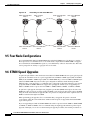
9.4 Path-Protected Mesh Networks
9.5 Four Node Configurations
9-6
9-8
9.6 STMN Speed Upgrades 9-8
9.6.1 Span Upgrade Wizard 9-9
9.6.2 Manual Span Upgrades 9-9
9.7 Overlay Ring Circuits
CHAPTER
10
9-9
Alarm Monitoring and Management
10.1 Overview
10-1
10-1
10.2 Viewing Alarms 10-1
10.2.1 Viewing Alarms With Each Node’s Time Zone
10.2.2 Controlling Alarm Display 10-4
10.2.3 Filtering Alarms 10-4
10.2.4 Viewing Alarm-Affected Circuits 10-4
10.2.5 Conditions Tab 10-5
10-3
Cisco ONS 15310-MA SDH Reference Manual, Release 9.1 and Release 9.2
viii
78-19417-01
Contents
10.2.6 Controlling the Conditions Display 10-5
10.2.6.1 Retrieving and Displaying Conditions 10-6
10.2.6.2 Conditions Column Descriptions 10-6
10.2.6.3 Filtering Conditions 10-7
10.2.7 Viewing History 10-7
10.2.7.1 History Column Descriptions 10-8
10.2.7.2 Retrieving and Displaying Alarm and Condition History
10.2.8 Alarm History and Log Buffer Capacities 10-9
10.3 Alarm Severities
10-8
10-9
10.4 Alarm Profiles 10-9
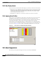
10.4.1 Creating and Modifying Alarm Profiles
10.4.2 Alarm Profile Buttons 10-10
10.4.3 Alarm Profile Editing 10-11
10.4.4 Alarm Severity Options 10-11
10.4.5 Row Display Options 10-12
10.4.6 Applying Alarm Profiles 10-12
10-10
10.5 Alarm Suppression 10-12
10.5.1 Alarms Suppressed for Maintenance 10-13
10.5.2 Alarms Suppressed by User Command 10-13
10.6 External Alarms and Controls 10-13
10.6.1 External Alarm Input 10-13
10.6.2 External Control Output 10-14
CHAPTER
11
Performance Monitoring
11-1
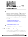
11.1 Threshold Performance Monitoring
11-1
11.2 Intermediate-Path Performance Monitoring
11-3
11.3 Pointer Justification Count Performance Monitoring
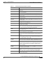
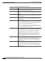
11.4 Performance Monitoring Parameter Definitions
11-3
11-4
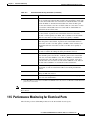
11.5 Performance Monitoring for Electrical Ports 11-13
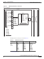
11.5.1 E1 Port Performance Monitoring Parameters 11-14
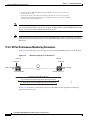
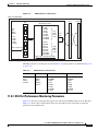
11.5.2 E3 Port Performance Monitoring Parameters 11-16
11.5.3 DS3 Port Performance Monitoring Parameters 11-17
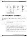
11.6 Performance Monitoring for Ethernet Cards 11-19
11.6.1 CE-100T-8, CE-MR-6, ML-100T-8 Card Ethernet Performance Monitoring Parameters 11-19
11.6.1.1 CE-100T-8, CE-MR-6, and ML-100T-8 Card Ether Ports Statistics Window 11-19
11.6.1.2 CE-100T-8, CE-MR-6, and ML-100T-8 Card Ether Ports Utilization Window 11-22
11.6.1.3 CE-100T-8, CE-MR-6, and ML-100T-8 Card Ether Ports History Window 11-22
11.6.1.4 CE-100T-8, CE-MR-6, and ML-100T-8 Card POS Ports Statistics Parameters 11-22
Cisco ONS 15310-MA SDH Reference Manual, Release 9.1 and Release 9.2
78-19417-01
ix
Contents
11.6.1.5 CE-100T-8, CE-MR-6, and ML-100T-8 Card POS Ports Utilization Window 11-24
11.6.1.6 CE-100T-8, CE-MR-6, and ML-100T-8 Card POS Ports History Window 11-25
11.7 Performance Monitoring for Optical Ports 11-25
11.7.1 STM1 Port Performance Monitoring Parameters 11-25
11.7.2 STM4 Port Performance Monitoring Parameters 11-27
11.7.3 STM16 Port Performance Monitoring Parameters for ONS 15310-MA SDH
CHAPTER
12
SNMP
11-29
12-1
12.1 SNMP Overview
12-1
12.2 SNMP Basic Components
12-2
12.3 SNMP Version Support 12-4
12.3.1 SNMPv3 Support 12-4
12.4 SNMP Message Types
12-4
12.5 SNMP Management Information Bases 12-5
12.5.1 IETF-Standard MIBs for the ONS 15310-MA SDH
12.5.2 Proprietary ONS 15310-MA SDH MIBs 12-6
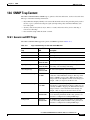
12.6 SNMP Trap Content 12-11
12.6.1 Generic and IETF Traps
12.6.2 Variable Trap Bindings
12.7 SNMPv1/v2 Community Names
12-11
12-12
12-12
12.8 SNMPv1/v2 Proxy Support Over Firewalls
12.9 SNMPv3 Proxy Configuration
12-5
12-13
12-13
12.10 SNMP Remote Monitoring 12-14
12.10.1 Ethernet Statistics Group 12-14
12.10.1.1 Row Creation in etherStatsTable 12-14
12.10.1.2 Get Requests and GetNext Requests 12-15
12.10.1.3 Row Deletion in etherStatsTable 12-15
12.10.1.4 64-Bit etherStatsHighCapacity Table 12-15
12.10.2 History Control Group 12-15
12.10.2.1 History Control Table 12-15
12.10.2.2 Row Creation in historyControlTable 12-16
12.10.2.3 Get Requests and GetNext Requests 12-16
12.10.2.4 Row Deletion in historyControl Table 12-16
12.10.3 Ethernet History RMON Group 12-16
12.10.3.1 64-Bit etherHistoryHighCapacityTable 12-16
12.10.4 Alarm RMON Group 12-17
12.10.4.1 Alarm Table 12-17
12.10.4.2 Row Creation in alarmTable 12-17
Cisco ONS 15310-MA SDH Reference Manual, Release 9.1 and Release 9.2
x
78-19417-01
Contents
12.10.4.3 Get Requests and GetNext Requests
12.10.4.4 Row Deletion in alarmTable 12-19
12.10.5 Event RMON Group 12-19
12.10.5.1 Event Table 12-19
12.10.5.2 Log Table 12-19
APPENDIX
A
Specifications
12-18
A-1
A.1 Cisco ONS 15310-MA SDH Shelf Specifications A-1
A.1.1 Alarm Interface A-1
A.1.2 UDC Interface A-2
A.1.3 Cisco Transport Controller LAN Interface A-2
A.1.4 TL1 Craft Interface A-2
A.1.5 Configurations A-2
A.1.6 LEDs A-3
A.1.7 Push Buttons A-3
A.1.8 BITS Interface A-3
A.1.9 System Timing A-3
A.1.10 Power Specifications A-4
A.1.11 Environmental Specifications A-4
A.1.12 Fan-Tray Assembly Specifications A-4
A.1.13 Shelf Dimensions A-4
A.2 Card Specifications A-5
A.2.1 15310E-CTX-K9 Card A-5
A.2.2 Nonvolatile Memory A-6
A.2.3 CE-100T-8 and ML-100T-8 Cards A-6
A.2.4 CE-MR-6 Card A-7
A.2.5 E1_21_E3_DS3_3 and E1_63_E3_DS3_3 Cards
A.2.6 Filler Cards A-9
A.3 SFP Specifications
A-9
A.4 Purcell FLX25GT Cabinet Specifications A-12
A.4.1 Power Specifications A-13
A.4.2 Environmental Specifications A-13
A.4.3 ONS 15310-MA SDH OSP Statements A-14
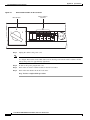
A.4.4 ONS 15310-MA OSP configuration A-15
Turn off or on AC power in Purcell FLX25GT OSP cabinet
APPENDIX
B
Administrative and Service States
B.1 Service States
A-7
A-15
B-1
B-1
B.2 Administrative States
B-2
Cisco ONS 15310-MA SDH Reference Manual, Release 9.1 and Release 9.2
78-19417-01
xi
Contents
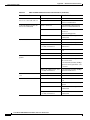
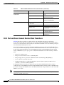
B.3 Service State Transitions B-3
B.3.1 Card Service State Transitions B-3
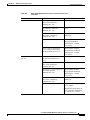
B.3.2 Port and Cross-Connect Service State Transitions B-6
B.3.3 Pluggable Equipment Service State Transitions B-13
APPENDIX
C
Network Element Defaults
C-1
C.1 Network Element Defaults Description
C.2 CTC Default Settings
C-1
C-2
C.3 Cisco ONS 15310-MA SDH Card Default Settings C-2
C.3.1 Configuration Defaults C-3
C.3.2 Threshold Defaults C-4
C.3.3 Defaults by Card C-4
C.3.3.1 15310E-CTX-K9 Card Default Settings C-5
C.3.3.2 E1_21_E3_DS3_3 Card Default Settings C-15
C.3.3.3 E1_63_E3_DS3_3 Card Default Settings C-21
C.3.3.4 Ethernet Card Default Settings C-28
C.4 Cisco ONS 15310-MA SDH Node Default Settings
C.4.1 Time Zones C-39
C-29
INDEX
Cisco ONS 15310-MA SDH Reference Manual, Release 9.1 and Release 9.2
xii
78-19417-01
F I G U R E S
Figure 1-1
ONS 15310-MA SDH Shelf Assembly Dimensions
1-3
Figure 1-2
Mounting a Single ONS 15310-MA SDH in a Rack
1-4
Figure 1-3
High-Density EIA Connectors
Figure 1-4
ONS 15310-MA SDH Door Ground Strap
Figure 1-5
Ground Holes on the Bottom of the ONS 15310-MA SDH Shelf Assembly
Figure 1-6
Ground Holes on the Left and Right Sides of the ONS 15310-MA SDH Shelf Assembly
Figure 1-7
ACS Cable T015654
Figure 1-8
32-PAIR/24-GAUGE T1 SHIELDED CABLE ASSEMBLY
Figure 1-9
25-PR 24-GA CORR-SHIELD OUTDOOR CABLE ASSEMBLY
Figure 1-10
Shelf Assembly with Fiber Guide Installed
Figure 1-11
BNC Insertion and Removal Tool
Figure 1-12
Installing the Standard Cable Management Bracket
1-22
Figure 1-13
Installing the Extended Cable Management Bracket
1-23
Figure 1-14
RJ-11 Cable Connector
Figure 1-15
Installing a Card in an ONS 15310-MA SDH
Figure 2-1
ONS 15310-MA SDH with Cards Installed
Figure 2-2
15310E-CTX-K9 Faceplate and Block Diagram
Figure 2-3
CE-100T-8 Faceplate and Block Diagram
Figure 2-4
CE-MR-6 Faceplate and Block Diagram
Figure 2-5
Console Cable Adapter
Figure 2-6
ML-100T-8 Card Faceplate and Block Diagram
Figure 2-7
E1_21_E3_DS3_3 and E1_63_E3_DS3_3 Card Faceplates and Block Diagram
Figure 2-8
BIC Configuration on WBE Cards
Figure 2-9
Filler Card
Figure 2-10
15310E-CTX-K9 Filler Card
Figure 2-11
Mylar Tab SFP
Figure 2-12
Actuator/Button SFP
Figure 2-13
Bail Clasp SFP
Figure 3-1
ONS 15310-MA SDH Chassis Card Layout
Figure 4-1
CTC Software Versions in an ONS 15310-MA SDH (Node View)
1-6
1-7
1-8
1-9
1-11
1-12
1-12
1-14
1-15
1-26
1-27
2-2
2-4
2-7
2-11
2-13
2-14
2-16
2-17
2-18
2-19
2-22
2-22
2-22
3-2
4-2
Cisco ONS 15310-MA SDH Reference Manual, Release 9.1 and Release 9.2
78-19417-01
xiii
Figures
Figure 4-2
ONS 15310-MA SDH Node View (Default Login View)
Figure 4-3
Terminal Loopback Indicator
Figure 4-4
Facility Loopback Indicator
Figure 4-5
Network in CTC Network View
Figure 4-6
CTC Card View of an E1_21_E3_DS3_3 Card
Figure 4-7
Static IP-Over-CLNS Tunnels
Figure 4-8
TL1 Tunnels
Figure 6-1
ONS 15310-MA SDH Timing Example
Figure 7-1
Terminal Loopback in the Edit Circuits Window
Figure 7-2
Subnetwork Connection Protection Go-and-Return Routing
Figure 7-3
VCAT Common Fiber Routing
Figure 7-4
VCAT Split Fiber Routing
Figure 7-5
Open-Ended VCAT
Figure 7-6
Rolls Window
Figure 7-7
Single Source Roll
Figure 7-8
Single Destination Roll
Figure 7-9
Single Roll from One Circuit to Another Circuit (Destination Changes)
Figure 7-10
Single Roll from One Circuit to Another Circuit (Source Changes)
Figure 7-11
Dual Roll to Reroute a Link
Figure 7-12
Dual Roll to Reroute to a Different Node
Figure 8-1
Scenario 1: CTC and ONS 15310-MA SDH Nodes on the Same Subnet
8-3
Figure 8-2
Scenario 2: CTC and ONS 15310-MA SDH Nodes Connected to Router
8-4
Figure 8-3
Scenario 3: Using Proxy ARP
Figure 8-4
Scenario 3: Using Proxy ARP with Static Routing
8-6
Figure 8-5
Scenario 4: Default Gateway on a CTC Computer
8-7
Figure 8-6
Scenario 5: Static Route with One CTC Computer Used as a Destination
Figure 8-7
Scenario 5: Static Route with Multiple LAN Destinations
Figure 8-8
Scenario 6: OSPF Enabled
Figure 8-9
Scenario 6: OSPF Not Enabled
Figure 8-10
ONS 15310-MA SDH Proxy Server with GNE and ENEs on the Same Subnet
Figure 8-11
Scenario 7: Proxy Server with GNE and ENEs on Different Subnets
Figure 8-12
Scenario 7: Proxy Server with ENEs on Multiple Rings
Figure 8-13
Proxy and Firewall Tunnels for Foreign Terminations
Figure 8-14
Foreign Node Connection to an ENE Ethernet Port
Figure 8-15
ISO-DCC NSAP Address
4-7
4-9
4-10
4-11
4-14
4-17
4-18
6-2
7-7
7-11
7-12
7-13
7-16
7-18
7-20
7-20
7-20
7-21
7-21
7-22
8-5
8-8
8-9
8-10
8-11
8-13
8-14
8-15
8-21
8-22
8-26
Cisco ONS 15310-MA SDH Reference Manual, Release 9.1 and Release 9.2
xiv
78-19417-01
Figures
Figure 8-16
Level 1 and Level 2 OSI Routing
Figure 8-17
Manual TARP Adjacencies
8-32
Figure 8-18
IP-over-CLNS Tunnel Flow
8-33
Figure 8-19
IP Over CLNS Tunnel Scenario 1: ONS NE to Other Vender GNE
Figure 8-20
IP-Over-CLNS Tunnel Scenario 2: ONS Node to Router
Figure 8-21
IP-Over-CLNS Tunnel Scenario 3: ONS Node to Router Across an OSI DCN
Figure 8-22
IPv6-IPv4 Interaction
Figure 9-1
Basic Four-Node SNCP Ring
Figure 9-2
Subnetwork Connection Protection with a Fiber Break
Figure 9-3
ONS 15310-MA SDH Linear ADM Configuration
Figure 9-4
ONS 15454 SDH with Two ONS 15310-MA SDH Nodes Subtending Linear Multiplex Section Protection
Configurations 9-4
Figure 9-5
ONS 15310-MA SDH with Two Subtending Linear Multiplex Section Protection Configurations
Figure 9-6
ONS 15310-MA SDH Ring Subtended from an ONS 15454 Ring
Figure 9-7
Linear or Linear Multiplex Section Protection Connection Between ONS 15454 and ONS 15310-MA SDH
Nodes 9-5
Figure 9-8
Path-Protected Mesh Network for ONS 15310-MA SDH Nodes
9-6
Figure 9-9
Path-Protected Mesh Network for ONS 15310-MA SDH Nodes
9-7
Figure 9-10
Virtual Ring for ONS 15310-MA SDH
Figure 9-11
Overlay Ring Circuit
Figure 10-1
ONS 15310-MA SDH Select Affected Circuits Option
Figure 10-2
Alarm Profile for a 15310-MA SDH 15310E-CTX-K9 Card
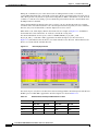
Figure 11-1
TCAs Displayed in CTC
Figure 11-2
Monitored Signal Types for the E1 Ports
Figure 11-3
PM Parameter Read Points on the E1 Ports
Figure 11-4
Monitored Signal Types for the E3 Ports
Figure 11-5
PM Read Points on the E3 Ports
Figure 11-6
Monitored Signal Types for the DS3 Port
Figure 11-7
PM Read Points on the DS3 Port
Figure 11-8
Monitored Signal Types for the STM1 Port
Figure 11-9
PM Parameter Read Points on the STM1 Port
Figure 11-10
Monitored Signal Types for the STM4 Ports
Figure 11-11
PM Parameter Read Points on the STM4 Ports
Figure 11-12
Monitored Signal Types for the STM16 Ports
Figure 11-13
PM Parameter Read Points on the STM16 Ports
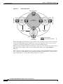
Figure 12-1
Basic Network Managed by SNMP
8-28
8-35
8-37
8-38
8-40
9-2
9-3
9-4
9-5
9-5
9-8
9-10
10-5
10-12
11-2
11-14
11-15
11-16
11-17
11-18
11-18
11-25
11-26
11-27
11-28
11-29
11-30
12-2
Cisco ONS 15310-MA SDH Reference Manual, Release 9.1 and Release 9.2
78-19417-01
xv
Figures
Figure 12-2
SNMP Agent Gathering Data from a MIB and Sending Traps to the Manager
Figure 12-3
Example of the Primary SNMP Components
Figure A-1
Valere rectifier breakers in AC load center
12-3
12-3
A-16
Cisco ONS 15310-MA SDH Reference Manual, Release 9.1 and Release 9.2
xvi
78-19417-01
T A B L E S
Table 1-1
E1 cables for wire-wrap connection
Table 1-2
Champ Connector Pin Assignments—Side-A EIA, Connectors J8 and J9; Side-B EIA, Connectors J21 and
J22 1-15
Table 1-3
Champ Connector Pin Assignments—Side-A EIA, Connectors J10 and J11; Side-B EIA, Connectors J23 and
J24 1-16
Table 1-4
Champ Connector Pin Assignments—Side-A EIA, Connectors J12 and J13; Side-B EIA, Connectors J25 and
J26 1-17
Table 1-5
Default Alarm Pin Assignments—Inputs
Table 1-6
Default Alarm Pin Assignments—Outputs
Table 1-7
BITS Cable Pin Assignments
1-20
Table 1-8
UDC Cable Pin Assignments
1-21
Table 1-9
Orderwire Pin Assignments
Table 1-10
Port Line Rates, Connector Types, and Locations
Table 2-1
ONS 15310-MA SDH Cards and Descriptions
Table 2-2
ONS 15310-MA SDH Software Release Compatibility Per Card
Table 2-3
15310E-CTX-K9 Card-Level Indicators
Table 2-4
CE-100T-8 Card-Level Indicators
2-8
Table 2-5
CE-100T-8 Port-Level Indicators
2-9
Table 2-6
CE-MR-6 Card-Level Indicators
2-12
Table 2-7
CE-MR-6 Port-Level Indicators
2-12
Table 2-8
ML-100T-8 Card-Level Indicators
2-15
Table 2-9
ML-100T-8 Port-Level Indicators
2-15
Table 2-10
E1_21_E3_DS3_3 and E1_63_E3_DS3_3 Card-Level Indicators
Table 2-11
SFP Card Compatibility
Table 4-1
CTC Computer Requirements
Table 4-2
ONS 15310-MA SDH Connection Methods
Table 4-3
Node View Card and Slot Colors
Table 4-4
Node View Card Port Colors and Service States
Table 4-5
Node View Card Statuses
Table 4-6
Node View Tabs and Subtabs
Table 4-7
Node Colors Indicating Status in Network View
1-12
1-19
1-19
1-25
1-27
2-2
2-3
2-5
2-18
2-20
4-4
4-6
4-8
4-9
4-10
4-10
4-12
Cisco ONS 15310-MA SDH Reference Manual, Release 9.1 and Release 9.2
78-19417-01
xvii
Tables
Table 4-8
Network View Tabs and Subtabs
Table 4-9
Link Icons
Table 4-10
Card View Tabs and Subtabs
Table 4-11
TL1 and Static IP-Over-CLNS Tunnels Comparison
4-18
Table 5-1
ONS 15310-MA SDH Security Levels—Node View
5-2
Table 5-2
ONS 15310-MA SDH Security Levels—Network View
Table 5-3
Default User Idle Times
Table 6-1
SSM Message Set
Table 6-2
SSM Generation 2 Message Set
Table 7-1
ONS 15310-MA SDH Circuit Status
Table 7-2
Circuit Protection Types
Table 7-3
Port State Color Indicators
Table 7-4
DCC Tunnels
Table 7-5
Switch Times
Table 7-6
ONS 15310-MA SDH Card VCAT Circuit Rates and Members
Table 7-7
ONS 15310-MA SDH VCAT Card Capabilities
Table 7-8
Protection options for Open-Ended VCAT Circuits
Table 7-9
ONS 15310-MA SDH Cards/Ports Capable of J1/J2 Path Trace
Table 7-10
Roll Statuses
Table 8-1
General P Troubleshooting Checklist
Table 8-2
ONS 15310-MA SDH GNE and ENE Settings
Table 8-3
Proxy Server Firewall Filtering Rules
Table 8-4
Proxy Server Firewall Filtering Rules When the Packet is Addressed to the ONS 15310-MA SDH
Table 8-5
Sample Routing Table Entries
Table 8-6
Ports Used by the 15310E-CTX-K9
Table 8-7
TCP/IP and OSI Protocols
Table 8-8
NSAP Fields
Table 8-9
TARP PDU Fields
8-29
Table 8-10
TARP PDU Types
8-30
Table 8-11
TARP Timers
Table 8-12
TARP Processing Flow
Table 8-13
IP Over CLNS Tunnel Cisco IOS Commands
Table 8-14
OSI Actions from the CTC Node View Provisioning Tab
Table 8-15
OSI Actions from the CTC Maintenance Tab
Table 8-16
Differences Between an IPv6 Node and an IPv4 Node
4-12
4-13
4-14
5-4
5-6
6-3
6-3
7-3
7-5
7-7
7-9
7-13
7-14
7-15
7-16
7-17
7-19
8-2
8-13
8-15
8-16
8-17
8-18
8-23
8-25
8-31
8-31
8-34
8-39
8-39
8-41
Cisco ONS 15310-MA SDH Reference Manual, Release 9.1 and Release 9.2
xviii
78-19417-01
Tables
Table 10-1
Alarms Column Descriptions
Table 10-2
Color Codes for Alarm and Condition Severities
Table 10-3
VC high-order path and Alarm Object Identification
Table 10-4
Alarm Display
Table 10-5
Conditions Display
Table 10-6
Conditions Column Description
Table 10-7
History Column Description
Table 10-8
Alarm Profile Buttons
Table 10-9
Alarm Profile Editing Options
Table 11-1
Electrical Ports that Report RX Direction for TCAs
Table 11-2
Performance Monitoring Parameters
Table 11-3
PM Parameters for E1 Ports
Table 11-4
PM Parameters for the E3 Ports
Table 11-5
DS3 Port PMs
Table 11-6
CE-100T-8, CE-MR-6, and ML-100T-8 Ether Ports Statistics Parameters
Table 11-7
maxBaseRate for VC high-order path Circuits
Table 11-8
Ethernet History Statistics per Time Interval
Table 11-9
CE-100T-8, CE-MR-6, and ML-100T-8 POS Ports Parameters for HDLC Mode
11-23
Table 11-10
CE-100T-8, CE-MR-6, and ML-100T-8 POS Ports Parameters for GFP-F Mode
11-23
Table 11-11
STM1 Port PM Parameters
11-26
Table 11-12
STM4 Port PM Parameters
11-28
Table 11-13
STM16 Port PM Parameters
Table 12-1
SNMP Message Types
Table 12-2
IETF Standard MIBs Implemented in the ONS 15310-MA SDH SNMP Agent
Table 12-3
ONS 15310-MA SDH Proprietary MIBs
Table 12-4
Supported IETF Traps for the ONS 15310-MA SDH
Table 12-5
Supported ONS 15310-MA SDH SNMPv2 Trap Variable Bindings
Table 12-6
RMON History Control Periods and History Categories
Table 12-7
OIDs Supported in the AlarmTable
Table A-1
LED Description
Table A-2
SFP Specifications
Table A-3
CE-MR-6 SFP Specifications
Table A-4
Single-Mode Fiber SFP Port Cabling Specifications
Table A-5
Multimode Fiber SFP Port Cabling Specifications
Table B-1
ONS 15310-MA SDH Service State Primary States and Primary State Qualifiers
10-2
10-2
10-3
10-4
10-6
10-6
10-8
10-10
10-11
11-2
11-4
11-15
11-17
11-19
11-20
11-22
11-22
11-30
12-5
12-5
12-7
12-11
12-12
12-15
12-17
A-3
A-10
A-10
A-11
A-12
B-1
Cisco ONS 15310-MA SDH Reference Manual, Release 9.1 and Release 9.2
78-19417-01
xix
Tables
Table B-2
ONS 15310-MA SDH Secondary States
Table B-3
ONS 15310-MA SDH Administrative States
Table B-4
ONS 15310-MA SDH Card Service State Transitions
Table B-5
ONS 15310-MA SDH Port and Cross-Connect Service State
Transitions B-7
Table B-6
ONS 15310-MA SDH Pluggable Equipment Service State Transitions
Table C-1
CTC Default Settings
Table C-2
15310E-CTX-K9 Card Default Settings
Table C-3
E1_21_E3_DS3_3 Card Default Settings
C-15
Table C-4
E1_63_E3_DS3_3 Card Default Settings
C-21
Table C-5
CE-MR-6, CE-100T-8, and ML-100T-8 Card Default Settings
Table C-6
Ethernet Card Default Settings
Table C-7
ONS 15310-MA SDH Node Default Settings
Table C-8
Time Zones
B-2
B-3
B-3
B-13
C-2
C-5
C-28
C-29
C-31
C-39
Cisco ONS 15310-MA SDH Reference Manual, Release 9.1 and Release 9.2
xx
78-19417-01
Preface
Note
The terms “Unidirectional Path Switched Ring” and "UPSR" may appear in Cisco literature. These terms
do not refer to using Cisco ONS 15xxx products in a unidirectional path switched ring configuration.
Rather, these terms, as well as “Path Protected Mesh Network” and “PPMN,” refer generally to Cisco's
path protection feature, which may be used in any topological network configuration. Cisco does not
recommend using its path protection feature in any particular topological network configuration.
This section explains the objectives, intended audience, and organization of this publication and
describes the conventions that convey instructions and other information.
This section provides the following information:
•
Revision History
•
Document Objectives
•
Audience
•
Related Documentation
•
Document Conventions
•
Obtaining Optical Networking Information
•
Obtaining Documentation and Submitting a Service Request
Revision History
Date
Notes
December 2009
Updated Figure1-7, ACS Cable T015654 in Chapter 1, “Cisco ONS 15310-MA
SDH Shelf Assembly Hardware”.
February 2010
Added section 1.5: Rear Cover to Chapter “Cisco ONs 15310-MA SDH Shelf
Assembly Hardware”
April 2010
Added a note in section “SNMP Overview” in the chapter “SNMP”.
July 2010
•
Updated the section “SFP Specifications” in the appendix “Specifications”.
•
Updated the section “CE-100T-8 and ML-100T-8 Cards” in the appendix
“Specifications”.
Cisco ONS 15310-MA SDH Reference Manual, Release 9.1 and Release 9.2
78-19417-01
xxi
Preface
Date
November 2010
December 2010
Notes
•
Added the section “Open-Ended VCAT” in the chapter “Circuits and
Tunnels”.
•
Updated the table “Switch Times” in the chapter “Circuits and Tunnels”.
•
Changed the CTX2500 card name to 15310E-CTX-K9 through out the
document.
•
Updated the section “CE-MR-6 Card” in the chapter “Card Reference”.
•
Updated the table "ONS 15310-MA SDH Security Levels—Node View" in
the chapter "Security".
January 2011
Updated the sections “CE-100T-8 Card” and “CE-MR-6 Card” in the chapter
“Card Reference”.
July 2011
Added a note in the “PC and UNIX Workstation Requirements” section of
Chapter, “Cisco Transport Controller Operation”.
March 2012
Updated the section “15310E-CTX-K9 Card” in the appendix “Specifications”.
August 2012
The full length book-PDF was generated.
Document Objectives
The Cisco ONS 15310-MA SDH Reference Manual provides hardware and software reference
information for Cisco ONS 15310 nodes and networks. Use this manual in conjunction with the
appropriate publications listed in the Related Documentation section.
Audience
To use this publication, you should be familiar with Cisco or equivalent optical transmission hardware
and cabling, telecommunications hardware and cabling, electronic circuitry and wiring practices, and
preferably have experience as a telecommunications technician.
Related Documentation
Use the Cisco ONS 15310-MA SDH Reference Manual in conjunction with the following referenced
publications:
•
Cisco ONS 15310-MA SDH Procedure Guide
Provides installation, turn up, test, and maintenance procedures.
•
Cisco ONS 15310-MA SDH Troubleshooting Guide
Provides alarm descriptions and troubleshooting procedures, general troubleshooting procedures,
error messages, performance monitoring parameters, and SNMP information.
•
Cisco ONS SONET TL1 Command Guide
Provides a full TL1 command and autonomous message set including parameters, AIDs, conditions
and modifiers for the Cisco ONS 15454, ONS 15600, and Cisco ONS 15310-MA SDH systems.
Cisco ONS 15310-MA SDH Reference Manual, Release 9.1 and Release 9.2
xxii
78-19417-01
Preface
•
Cisco ONS SONET TL1 Reference Guide
Provides general information, procedures, and errors for TL1 in the Cisco ONS 15454, ONS 15600,
and Cisco ONS 15310-MA SDH systems.
•
Cisco ONS 15310-CL and Cisco ONS 15310-MA SDH Ethernet Card Software Feature and
Configuration Guide
Provides software feature and operation information for Ethernet cards in the Cisco ONS 15310-MA
SDH.
•
Release Notes for the Cisco ONS 15310-MA SDH Release 9.1 and 9.2
Provides new features and functionality information.
For an update on End-of-Life and End-of-Sale notices, refer to
http://www.cisco.com/en/US/products/hw/optical/ps2001/prod_eol_notices_list.html.
Document Conventions
This publication uses the following conventions:
Convention
Application
boldface
Commands and keywords in body text.
italic
Command input that is supplied by the user.
[
Keywords or arguments that appear within square brackets are optional.
]
{x|x|x}
A choice of keywords (represented by x) appears in braces separated by
vertical bars. The user must select one.
Ctrl
The control key. For example, where Ctrl + D is written, hold down the
Control key while pressing the D key.
screen font
Examples of information displayed on the screen.
boldface screen font
Examples of information that the user must enter.
<
Command parameters that must be replaced by module-specific codes.
>
Note
Means reader take note. Notes contain helpful suggestions or references to material not covered in the
document.
Caution
Means reader be careful. In this situation, the user might do something that could result in equipment
damage or loss of data.
Cisco ONS 15310-MA SDH Reference Manual, Release 9.1 and Release 9.2
78-19417-01
xxiii
Preface
Warning
IMPORTANT SAFETY INSTRUCTIONS
This warning symbol means danger. You are in a situation that could cause bodily injury. Before you
work on any equipment, be aware of the hazards involved with electrical circuitry and be familiar
with standard practices for preventing accidents. Use the statement number provided at the end of
each warning to locate its translation in the translated safety warnings that accompanied this
device. Statement 1071
SAVE THESE INSTRUCTIONS
Waarschuwing
BELANGRIJKE VEILIGHEIDSINSTRUCTIES
Dit waarschuwingssymbool betekent gevaar. U verkeert in een situatie die lichamelijk letsel kan
veroorzaken. Voordat u aan enige apparatuur gaat werken, dient u zich bewust te zijn van de bij
elektrische schakelingen betrokken risico's en dient u op de hoogte te zijn van de standaard
praktijken om ongelukken te voorkomen. Gebruik het nummer van de verklaring onderaan de
waarschuwing als u een vertaling van de waarschuwing die bij het apparaat wordt geleverd, wilt
raadplegen.
BEWAAR DEZE INSTRUCTIES
Varoitus
TÄRKEITÄ TURVALLISUUSOHJEITA
Tämä varoitusmerkki merkitsee vaaraa. Tilanne voi aiheuttaa ruumiillisia vammoja. Ennen kuin
käsittelet laitteistoa, huomioi sähköpiirien käsittelemiseen liittyvät riskit ja tutustu
onnettomuuksien yleisiin ehkäisytapoihin. Turvallisuusvaroitusten käännökset löytyvät laitteen
mukana toimitettujen käännettyjen turvallisuusvaroitusten joukosta varoitusten lopussa näkyvien
lausuntonumeroiden avulla.
SÄILYTÄ NÄMÄ OHJEET
Attention
IMPORTANTES INFORMATIONS DE SÉCURITÉ
Ce symbole d'avertissement indique un danger. Vous vous trouvez dans une situation pouvant
entraîner des blessures ou des dommages corporels. Avant de travailler sur un équipement, soyez
conscient des dangers liés aux circuits électriques et familiarisez-vous avec les procédures
couramment utilisées pour éviter les accidents. Pour prendre connaissance des traductions des
avertissements figurant dans les consignes de sécurité traduites qui accompagnent cet appareil,
référez-vous au numéro de l'instruction situé à la fin de chaque avertissement.
CONSERVEZ CES INFORMATIONS
Warnung
WICHTIGE SICHERHEITSHINWEISE
Dieses Warnsymbol bedeutet Gefahr. Sie befinden sich in einer Situation, die zu Verletzungen führen
kann. Machen Sie sich vor der Arbeit mit Geräten mit den Gefahren elektrischer Schaltungen und
den üblichen Verfahren zur Vorbeugung vor Unfällen vertraut. Suchen Sie mit der am Ende jeder
Warnung angegebenen Anweisungsnummer nach der jeweiligen Übersetzung in den übersetzten
Sicherheitshinweisen, die zusammen mit diesem Gerät ausgeliefert wurden.
BEWAHREN SIE DIESE HINWEISE GUT AUF.
Cisco ONS 15310-MA SDH Reference Manual, Release 9.1 and Release 9.2
xxiv
78-19417-01
Preface
Avvertenza
IMPORTANTI ISTRUZIONI SULLA SICUREZZA
Questo simbolo di avvertenza indica un pericolo. La situazione potrebbe causare infortuni alle
persone. Prima di intervenire su qualsiasi apparecchiatura, occorre essere al corrente dei pericoli
relativi ai circuiti elettrici e conoscere le procedure standard per la prevenzione di incidenti.
Utilizzare il numero di istruzione presente alla fine di ciascuna avvertenza per individuare le
traduzioni delle avvertenze riportate in questo documento.
CONSERVARE QUESTE ISTRUZIONI
Advarsel
VIKTIGE SIKKERHETSINSTRUKSJONER
Dette advarselssymbolet betyr fare. Du er i en situasjon som kan føre til skade på person. Før du
begynner å arbeide med noe av utstyret, må du være oppmerksom på farene forbundet med
elektriske kretser, og kjenne til standardprosedyrer for å forhindre ulykker. Bruk nummeret i slutten
av hver advarsel for å finne oversettelsen i de oversatte sikkerhetsadvarslene som fulgte med denne
enheten.
TA VARE PÅ DISSE INSTRUKSJONENE
Aviso
INSTRUÇÕES IMPORTANTES DE SEGURANÇA
Este símbolo de aviso significa perigo. Você está em uma situação que poderá ser causadora de
lesões corporais. Antes de iniciar a utilização de qualquer equipamento, tenha conhecimento dos
perigos envolvidos no manuseio de circuitos elétricos e familiarize-se com as práticas habituais de
prevenção de acidentes. Utilize o número da instrução fornecido ao final de cada aviso para
localizar sua tradução nos avisos de segurança traduzidos que acompanham este dispositivo.
GUARDE ESTAS INSTRUÇÕES
¡Advertencia!
INSTRUCCIONES IMPORTANTES DE SEGURIDAD
Este símbolo de aviso indica peligro. Existe riesgo para su integridad física. Antes de manipular
cualquier equipo, considere los riesgos de la corriente eléctrica y familiarícese con los
procedimientos estándar de prevención de accidentes. Al final de cada advertencia encontrará el
número que le ayudará a encontrar el texto traducido en el apartado de traducciones que acompaña
a este dispositivo.
GUARDE ESTAS INSTRUCCIONES
Varning!
VIKTIGA SÄKERHETSANVISNINGAR
Denna varningssignal signalerar fara. Du befinner dig i en situation som kan leda till personskada.
Innan du utför arbete på någon utrustning måste du vara medveten om farorna med elkretsar och
känna till vanliga förfaranden för att förebygga olyckor. Använd det nummer som finns i slutet av
varje varning för att hitta dess översättning i de översatta säkerhetsvarningar som medföljer denna
anordning.
SPARA DESSA ANVISNINGAR
Cisco ONS 15310-MA SDH Reference Manual, Release 9.1 and Release 9.2
78-19417-01
xxv
Preface
Cisco ONS 15310-MA SDH Reference Manual, Release 9.1 and Release 9.2
xxvi
78-19417-01
Preface
Aviso
INSTRUÇÕES IMPORTANTES DE SEGURANÇA
Este símbolo de aviso significa perigo. Você se encontra em uma situação em que há risco de lesões
corporais. Antes de trabalhar com qualquer equipamento, esteja ciente dos riscos que envolvem os
circuitos elétricos e familiarize-se com as práticas padrão de prevenção de acidentes. Use o
número da declaração fornecido ao final de cada aviso para localizar sua tradução nos avisos de
segurança traduzidos que acompanham o dispositivo.
GUARDE ESTAS INSTRUÇÕES
Advarsel
VIGTIGE SIKKERHEDSANVISNINGER
Dette advarselssymbol betyder fare. Du befinder dig i en situation med risiko for
legemesbeskadigelse. Før du begynder arbejde på udstyr, skal du være opmærksom på de
involverede risici, der er ved elektriske kredsløb, og du skal sætte dig ind i standardprocedurer til
undgåelse af ulykker. Brug erklæringsnummeret efter hver advarsel for at finde oversættelsen i de
oversatte advarsler, der fulgte med denne enhed.
GEM DISSE ANVISNINGER
Cisco ONS 15310-MA SDH Reference Manual, Release 9.1 and Release 9.2
78-19417-01
xxvii
Preface
Cisco ONS 15310-MA SDH Reference Manual, Release 9.1 and Release 9.2
xxviii
78-19417-01
Preface
Obtaining Optical Networking Information
This section contains information that is specific to optical networking products. For information that
pertains to all of Cisco, refer to the Obtaining Documentation and Submitting a Service Request section.
Where to Find Safety and Warning Information
For safety and warning information, refer to the Cisco Optical Transport Products Safety and
Compliance Information document that accompanied the product. This publication describes the
international agency compliance and safety information for the Cisco ONS 15310 system. It also
includes translations of the safety warnings that appear in the ONS 15310 system documentation.
Cisco Optical Networking Product Documentation CD-ROM
Optical networking-related documentation, including Cisco ONS 15xxx product documentation, is
available in a CD-ROM package that ships with your product. The Optical Networking Product
Documentation CD-ROM is updated periodically and may be more current than printed documentation.
Obtaining Documentation and Submitting a Service Request
For information on obtaining documentation, submitting a service request, and gathering additional
information, see the monthly What’s New in Cisco Product Documentation, which also lists all new and
revised Cisco technical documentation, at:
http://www.cisco.com/en/US/docs/general/whatsnew/whatsnew.html
Subscribe to the What’s New in Cisco Product Documentation as a Really Simple Syndication (RSS) feed
and set content to be delivered directly to your desktop using a reader application. The RSS feeds are a free
service and Cisco currently supports RSS version 2.0.
Cisco ONS 15310-MA SDH Reference Manual, Release 9.1 and Release 9.2
78-19417-01
xxix
Preface
Cisco ONS 15310-MA SDH Reference Manual, Release 9.1 and Release 9.2
xxx
78-19417-01
CH A P T E R
1
Cisco ONS 15310-MA SDH Shelf Assembly
Hardware
This chapter provides a description of Cisco ONS 15310-MA SDH shelf hardware. Instructions for
installing equipment are provided in the Cisco ONS 15310-MA SDH Procedure Guide.
Chapter topics include:
•
1.1 Installation Overview, page 1-1
•
1.2 Rack Installation, page 1-2
•
1.3 Electrical Interface Assemblies, page 1-5
•
1.6 Power and Ground Description, page 1-7
•
1.7 Shelf Temperature, page 1-10
•
1.8 Cable Description and Installation, page 1-10
•
1.10 Fan-Tray Assembly, page 1-23
•
1.11 Cards and Slots, page 1-26
1.1 Installation Overview
You can mount the ONS 15310-MA SDH in a 19-inch (482.6 mm) or 600x600 mm ETSI rack.
The ONS 15310-MA SDH is powered using –48 VDC power. DC power connections are accessed from
the rear of the shelf assembly. ONS 15310-MA SDH Ethernet and optical ports are accessible at the front
of the shelf assembly, and electrical connections (E1, E3/DS3) are accessible at the rear of the shelf
assembly through electrical interface assemblies (EIAs).
When installed in an equipment rack, the ONS 15310-MA SDH assembly is typically connected to a fuse
and alarm panel that provides centralized alarm connection points and distributed power for the
ONS 15310-MA SDH. Fuse and alarm panels are third-party equipment and are not described in this
documentation. If you are unsure about the requirements or specifications for a fuse and alarm panel,
consult the documentation for that product.
Note
In this chapter, the terms “ONS 15310-MA SDH” and “shelf assembly” are used interchangeably. In the
installation context, these terms have the same meaning. Otherwise, shelf assembly refers to the physical
steel enclosure that holds cards and connects power, and ONS 15310-MA SDH refers to the entire
system, both hardware and software.
Cisco ONS 15310-MA SDH Reference Manual, Release 9.1 and Release 9.2
78-19417-01
1-1
Chapter 1
Cisco ONS 15310-MA SDH Shelf Assembly Hardware
Rack Installation
Note
The ONS 15310-MA SDH is suitable for installation in network telecommunication facilities where
National Electric Code (NEC) applies.
Install the ONS 15310-MA SDH in compliance with your local and national electrical codes:
•
United States: National Fire Protection Association (NFPA) 70; United States National Electrical
Code
•
Canada: Canadian Electrical Code, Part I, CSA C22.1
•
Other countries: If local and national electrical codes, are not available, refer to IEC 364, Part 1
through Part 7
Detailed compliance and safety information is provided in the Cisco Optical Transport Products Safety
and Compliance Information document that ships with the Cisco ONS 15310-MA SDH.
1.2 Rack Installation
The ONS 15310-MA SDH is easily mounted in a 19-inch (482.6 mm) or 600x600 mm equipment rack.
The shelf assembly can be mounted so that it projects five inches from the front of the rack. It mounts
in both EIA-standard and Telcordia-standard racks. A single shelf assembly is 10.67 inches (27.1 mm)
wide and occupies 6 RUs (10.5 in. [267.6 mm]) in a rack when installed with a standard cable
management bracket. If an extended cable management bracket is installed below the shelf assembly, an
additional RU is occupied, for a total of 7 RUs (12.25 in. [311.1 mm]).
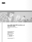
The ONS 15310-MA SDH measures 10.44 inches (26.51 cm) high, 10.67 inches (27.10 cm) wide, and
12 inches (20.48 cm) deep. Figure 1-1 shows the dimensions of the ONS 15310-MA SDH shelf
assembly.
Cisco ONS 15310-MA SDH Reference Manual, Release 9.1 and Release 9.2
1-2
78-19417-01
Chapter 1
Cisco ONS 15310-MA SDH Shelf Assembly Hardware
Rack Installation
Figure 1-1
ONS 15310-MA SDH Shelf Assembly Dimensions
12 inches (20.48 cm) deep
10.67 inches (27.10 cm) wide
144688
10.44 inches
(26.51 cm) high
1.2.1 Mounting Brackets
Caution
Use only the fastening hardware provided with the ONS 15310-MA SDH to prevent loosening,
deterioration, and electromechanical corrosion of the hardware and joined material.
Caution
When mounting the ONS 15310-MA SDH in a frame with a nonconductive coating (such as paint,
lacquer, or enamel) use either the thread-forming screws provided with the ONS 15310-MA SDH
shipping kit or remove the coating from the threads to ensure electrical continuity.
The shelf assembly ships without mounting brackets. You need to purchase brackets suitable either for
use with 19-inch (482.6mm) or 600x600mm racks.
Cisco ONS 15310-MA SDH Reference Manual, Release 9.1 and Release 9.2
78-19417-01
1-3
Chapter 1
Cisco ONS 15310-MA SDH Shelf Assembly Hardware
Rack Installation
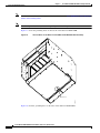
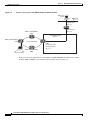
1.2.2 Mounting a Single Node
Mounting the ONS 15310-MA SDH in a rack requires a minimum of 10.5 inches of vertical rack space.
To ensure that the mounting is secure, use four #12-24 mounting screws for each side of the shelf
assembly. If the larger cable router is used, 12.5 inches of rack space is required.
Figure 1-2 shows a single ONS 15310-MA SDH being mounted in a rack, using a universal bracket.
Mounting a Single ONS 15310-MA SDH in a Rack
144705
Figure 1-2
Cisco ONS 15310-MA SDH Reference Manual, Release 9.1 and Release 9.2
1-4
78-19417-01
Chapter 1
Cisco ONS 15310-MA SDH Shelf Assembly Hardware
Electrical Interface Assemblies
1.2.3 Mounting Multiple Nodes
Most standard 2200 mm racks can hold numerous (up to 6 or 7) ONS 15310-MA SDH nodes and a fuse
and alarm panel.
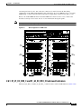
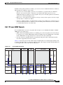
1.3 Electrical Interface Assemblies
High-density EIAs are attached to the ONS 15310-MA SDH shelf assembly backplane to provide up to
126 transmit and receive E1 connections through six Champ connectors per side (A and B) or six
transmit and receive E3/DS3 connections through six BNC connectors per side. The EIAs are designed
to support E1, E3/DS3 signals. The appropriate cable assembly is required depending on the type of
signal.
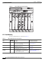
You can install EIAs on one or both sides of the ONS 15310-MA SDH. As you face the rear of the shelf
assembly, the right side is the A side (15310-EIA-HD-A) and the left side is the B side
(15310-EIA-HD-B).
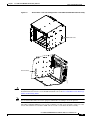
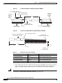
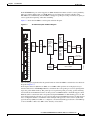
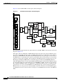
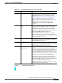
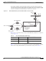
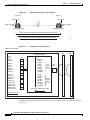
Figure 1-3 shows the J connectors on the A- and B-side high-density EIAs installed on the
ONS 15310-MA SDH.
Cisco ONS 15310-MA SDH Reference Manual, Release 9.1 and Release 9.2
78-19417-01
1-5
Chapter 1
Cisco ONS 15310-MA SDH Shelf Assembly Hardware
Front Door
High-Density EIA Connectors
J5-BITS2
RTN -48VDC PWR B
J1-LAN
J2-CRFT
J3-UDC
J7-ALM OUT
J4-BITS1
P/N
J29-OUT
J27-OUT
J30-IN
2
J28-IN
S/N
CLEI CODE
CLEI CODE
E1
IN
J24
BAR CODE
E1
OUT
J23
S/N
E1
IN
J22
BAR CODE
E1
OUT
J21
PID VID
COO
PID VID
P/N
1
PWR A -48VDC RTN
J6-ALM INPUT
COO
E1
OUT
J8
E1
IN
J9
E1
OUT
J10
E1
IN
J11
E1
OUT
J25
E1
OUT
J12
E1
IN
J26
E1
IN
J13
J31-OUT
J15-IN
3
1
J32-IN
J33-HD DS3
J16-OUT
J17-IN
2
J14-OUT
3
J18-OUT
J19-IN
271766
Figure 1-3
J20-HD DS3
To install the EIA on the rear of the shelf assembly, you must first remove the standard sheet metal
covers. The EIAs use the same screw holes as the standard sheet metal covers, but they use three holes
for panhead screws and two holes for jack screws.
When installed with the standard door and cabling on the backplane, the ONS 15310-MA SDH shelf
measures approximately 13.7 inches (34.8 cm) deep when fully populated with backplane cables.
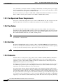
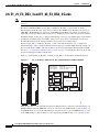
1.4 Front Door
The ONS 15310-MA SDH is orderable with a front door. You must install the ground strap on the door
after you install the door (Figure 1-4).
Cisco ONS 15310-MA SDH Reference Manual, Release 9.1 and Release 9.2
1-6
78-19417-01
Chapter 1
Cisco ONS 15310-MA SDH Shelf Assembly Hardware
Rear Cover
ONS 15310-MA SDH Door Ground Strap
144706
Figure 1-4
1.5 Rear Cover
The ONS 15310-MA SDH is orderable with an optional, clear-plastic, rear cover. The rear cover protects
the connectors installed on the back plane of the chassis.
Rear cover specifications are:
•
Environmental
– Operating temperature: –40 to +65 degrees Celsius (–40 to +149 degrees Fahrenheit)
– Operating humidity: 5 to 95%, noncondensing
•
Dimensions
– 10.59 in. x 10.44 in. x 0.5 in. (26.9 cm x 26.52 cm x 1.27 cm)
– Weight: Approximately 0.67 lb (300 g)
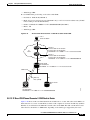
1.6 Power and Ground Description
This section describes how to connect the ONS 15310-MA SDH shelf assembly to the power supply. For
detailed procedures, refer to the “Install the Cisco ONS 15310-MA SDH” chapter in the
Cisco ONS 15310-MA SDH Procedure Guide. Terminate the chassis ground (located on both sides of the
rear of the shelf assembly or at the bottom of the shelf assembly) to either the office ground or rack
ground before you install the power. Use the grounding lug to attach the #6 AWG ground cable to the
#10-32 mount ground lug on the shelf assembly according to local site practice.
Ground one cable to ground the shelf assembly. Terminate the other end of the rack ground cable to
ground according to local site practice.
Cisco ONS 15310-MA SDH Reference Manual, Release 9.1 and Release 9.2
78-19417-01
1-7
Chapter 1
Cisco ONS 15310-MA SDH Shelf Assembly Hardware
Power and Ground Description
Note
For detailed instructions on how to ground the chassis, refer to the Cisco ONS Electrostatic Discharge
(ESD) and Grounding Guide.
Note
Additional ground cables may be added depending on the local site practice.
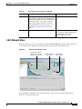
Figure 1-5 shows the grounding holes on the bottom of the ONS 15310-MA SDH.
Figure 1-5
Ground Holes on the Bottom of the ONS 15310-MA SDH Shelf Assembly
144707
Ground holes
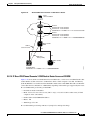
Figure 1-6 show the grounding holes on the sides of the ONS 15310-MA SDH.
Cisco ONS 15310-MA SDH Reference Manual, Release 9.1 and Release 9.2
1-8
78-19417-01
Chapter 1
Cisco ONS 15310-MA SDH Shelf Assembly Hardware
Power and Ground Description
Figure 1-6
Ground Holes on the Left and Right Sides of the ONS 15310-MA SDH Shelf Assembly
Ground holes
144708
Ground holes
Caution
Note
Always use the supplied ESD wristband when working with a powered ONS 15310-MA SDH. For
detailed instructions on how to wear the ESD wristband, refer to the Cisco ONS Electrostatic Discharge
(ESD) and Grounding Guide.
Use an external disconnect for service purposes and install it according to local site practice.
The ONS 15310-MA SDH DC power provides redundant –48 VDC power terminals on the rear of the
chassis. The terminals are labeled A and B and are located at each end of the shelf assembly.
Cisco ONS 15310-MA SDH Reference Manual, Release 9.1 and Release 9.2
78-19417-01
1-9
Chapter 1
Cisco ONS 15310-MA SDH Shelf Assembly Hardware
Shelf Temperature
To install redundant power feeds, use four power cables and one ground cable. For a single power feed,
only two power cables and one ground cable are required. A 1-inch (minimum) wide copper braid is
required to ground the ONS 15310-MA SDH outside plant (OSP) cabinet and is recommended for indoor
installations. For example, central office.Use #12 AWG power cables and a #6 AWG ground cable and,
to ensure circuit overcurrent protection, use a conductor with low impedance. The conductor must have
the capability to safely conduct any fault current that might be imposed. Do not use aluminum
conductors.
Note
The DC power Battery Return (BR) or positive terminal, must be grounded at the source end (power feed
or DC mains power end). The DC power BR input terminal of the ONS 15xxx is not connected to the
equipment frame (chassis).
Caution
If the system loses power or the 15310E-CTX-K9 card is reset, you must reset the ONS 15310-MA SDH
clock unless the node has been previously provisioned to use Simple Network Time Protocol (SNTP).
SNTP updates the clock over the LAN.
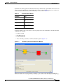
1.7 Shelf Temperature
The ONS 15310-MA SDH chassis temperature is displayed in the Shelf view > Provisioning > General
> Voltage/Temperature pane in CTC. The temperature of the shelf (in degrees Celsius) is displayed in
the Temperature area of the Voltage/Temperature pane.
Note
For ONS 15310-MA SDH chassis, voltage monitoring is not performed.
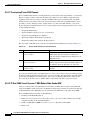
1.8 Cable Description and Installation
This section describes fiber-optic, E3 (coaxial), E1 (64-pin Champ), UDC, and twisted-pair cables.
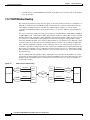
1.8.1 Cabling Types
The following types of cables are used with the ONS 15310-MA SDH:
•
Optical cables: The STM1/4/16 signals operate over fiber spans through SFP optics, including
intermediate-reach (IR) and long-reach (LR) SFPs. Specification references can be found for the
interface in ITU G.957 and Telcordia GR-253. See the “1.8.2 Fiber Cable Installation” section on
page 1-13 for more information. Make sure the fiber cables do not bend excessively; maintaining a
proper bend radius prevents damage to the optical cable.
•
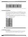
E1 cables: E1 cables (shielded, twisted-pair) connect to the electrical ports at the rear of the shelf
assembly using Champ cable connectors. E1 cables carry E1 traffic to and from the ONS 15310-MA
SDH. The ONS 15310-MA SDH supports up to three transmit and three receive Champ-64
connectors on each side of the shelf assembly, for a maximum of 63 E1 signals per side of the shelf,
28+28+7
A compatible E1 cable is available from Lorom Industrial Co., LTD.
Cisco ONS 15310-MA SDH Reference Manual, Release 9.1 and Release 9.2
1-10
78-19417-01
Chapter 1
Cisco ONS 15310-MA SDH Shelf Assembly Hardware
Cable Description and Installation
Lorom Industrial Co., LTD.
15th Floor, Room 2, Number 78, Sec 2
AN-HO Road
Taipei, Taiwan
Phone: 886-2-2706-6037
Fax: 886-2-2704-6396
POC: [email protected]
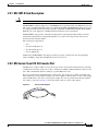
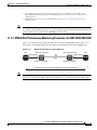
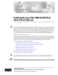
The ACS part number and description are: T015654-Length. Cable assembly with the cable exit at
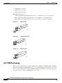
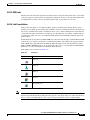
1 & 33. This cable solution offers two screw points on the cable head for attachment, see Figure 1-7
on page 1-11, and is equivalent in characteristics to the defacto 1161A rated cable.
Figure 1-7
1
Front view
33
ACS Cable T015654
32
64
64 position male Telco connector
1/8” clear heatshrink covering screw
32 & 64
Main label
P1 label
240751
Top view of hood
1 & 33
Refer to Table 2-1 for compatible E1 cables available from Lorom Industrial Co., LTD.
Lorom Industrial Co., LTD.
15th Floor, Room 2, Number 78, Sec 2
AN-HO Road
Taipei, Taiwan
Phone: 886-2-2706-6037
Fax: 886-2-2704-6396
Cisco ONS 15310-MA SDH Reference Manual, Release 9.1 and Release 9.2
78-19417-01
1-11
Chapter 1
Cisco ONS 15310-MA SDH Shelf Assembly Hardware
Cable Description and Installation
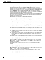
32-PAIR/24-GAUGE T1 SHIELDED CABLE ASSEMBLY
22-16 GA. x .25 bolt term.
ring, T&B
20 GA. stranded green
PVC hookup wire, alpha
4-40 x 425
captive
P.H.M.S.,
AMP
4-40 x 425
captive
P.H.M.S.,
AMP
xxx
274042
Figure 1-8
32-PR 24-GA T1
shielded cable, ADC
64-pin male
connector, AMP
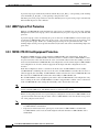
Figure 1-9
Pin 1
Pin 1
64-pin male bail-lock
connector, AMP
25-PR 24-GA CORR-SHIELD OUTDOOR CABLE ASSEMBLY
1/2" 2:1 Heat shrink, black
25-PR 24-GA CORR-Shield
outdoor cable, general
50-Pin male
710 splice connector, 3M
274041
xxx
Pin 1
50-POS
710 cover, 3M
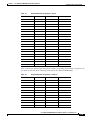
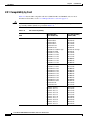
Table 1-1
ACS Part Numbers
Length
Description
PCAM90SPA0PC001
25 feet
Connector-Wire Wrap, DSX
PCAM90SPA1OC001
50 feet
Connector-Wire Wrap, DSX
PCAM90SPA3MC001
100 feet
Connector-Wire Wrap, DSX
PCAM90SPA7IC001
200 feet
Connector-Wire Wrap, DSX
•
Warning
E1 cables for wire-wrap connection
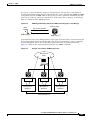
Coaxial cables: Coaxial cables connect to the electrical ports using BNC cable connectors. Coaxial
cables carry E3/DS3 traffic to and from the ONS 15310-MA SDH. The ONS 15310-MA SDH
supports up to three transmit and three receive coaxial connectors on each shelf assembly.
The E1/E3 ports on the ONS 15310-MA SDH are intra-building ports and are suitable only for
connecting to shielded cabling grounded at both ends. Statement 1084
Cisco ONS 15310-MA SDH Reference Manual, Release 9.1 and Release 9.2
1-12
78-19417-01
Chapter 1
Cisco ONS 15310-MA SDH Shelf Assembly Hardware
Cable Description and Installation
Note
In ONS 15310-MA SDH OSP installations, E1/E3 ports are connected to the OSP. The OSP cabinet is
equipped with primary and secondary protections. In addition, isolation transformers are also provided.
•
RJ-45 cables: RJ-45 cables connect to the LAN, CRAFT, and UDC ports. An unshielded
twisted-pair (STP) #22 or #24 AWG wire is required for the CRAFT and UDC ports. Unshielded
twisted-pair is sufficient for the alarm and LAN(rear). 10/100-Mbps RJ-45 Ethernet STP (Shielded
Twisted Pair) cables are used to connect the CE-100T-8 and ML-100T-8 cards.
•
Alarm and timing (BITS) cables: The Alarm In port requires a shielded cable terminated with a
DB-37 connector; Alarm Out requires a shielded cable terminated with a DB-25 connector; and the
building integrated timing supply (BITS) ports require DB-9 connectors or a DB9BIT=BB9 to wire
wrap adapter.
1.8.2 Fiber Cable Installation
To install fiber-optic cables on the ONS 15310-MA SDH, a fiber cable with an LC connector must be
connected to an SFP. SFPs are installed in the SFP port on the ONS 15310-MA SDH. Each LC connector
contains the transmit (Tx) and receive (Rx) signal for that port. Cisco recommends that you label the
transmit and receive ports and the working and protection fibers at each end of the fiber span to avoid
confusion with cables that are similar in appearance.
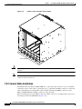
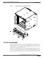
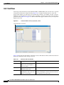
You can route fiber cables through the optional fiber guide, installed at the bottom of the shelf assembly
(Figure 1-10).
Cisco ONS 15310-MA SDH Reference Manual, Release 9.1 and Release 9.2
78-19417-01
1-13
Chapter 1
Cisco ONS 15310-MA SDH Shelf Assembly Hardware
Cable Description and Installation
Shelf Assembly with Fiber Guide Installed
144704
Figure 1-10
Fiber guide
Caution
You must provide some type of strain relief for the cables, using either a tie-bar or other site-specific
solution.
Note
Clean all fiber connectors thoroughly. Dust particles can degrade performance. Put caps on any fiber
connectors that you do not use.
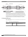
1.8.3 Coaxial Cable Installation
For E3/DS3 traffic, the ONS 15310-MA SDH uses coaxial cables and connectors. Cisco recommends
connecting a 735A coaxial cable to a patch panel. Use a compatible male BNC connector to connect the
cable to the E3/DS3 ports. The E3/DS3 cables should be terminated with BNC connectors on the
ONS 15310-MA SDH side and BNC connectors on the client side.
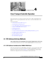
Due to the minimal space between BNC connectors and E1 connectors, you might require a special tool
for inserting and removing BNC EIAs (Figure 1-11).
Cisco ONS 15310-MA SDH Reference Manual, Release 9.1 and Release 9.2
1-14
78-19417-01
Chapter 1
Cisco ONS 15310-MA SDH Shelf Assembly Hardware
Cable Description and Installation
BNC Insertion and Removal Tool
44552
Figure 1-11
This tool can be obtained with P/N 227-T1000 from:
Amphenol USA (www.amphenol.com)
One Kennedy Drive
Danbury, CT 06810
Phone: 203 743-9272 Fax: 203 796-2032
This tool can be obtained with P/N RT-1L from:
Trompeter Electronics Inc. (www.trompeter.com)
31186 La Baya Drive
Westlake Village, CA 91362-4047
Phone: 800 982-2629 Fax: 818 706-1040
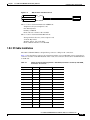
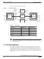
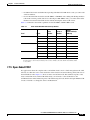
1.8.4 E1 Cable Installation
The ONS 15310-MA SDH uses 64-pin Champ connector cabling for E1 connections.
Table 1-2 lists the Champ connector pin assignments and the corresponding EIA connector mapping for
connectors J8 and J9 on the EIA installed on the A side, and connectors J21 and J22 on the EIA installed
on the B side.
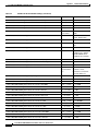
Table 1-2
Champ Connector Pin Assignments—Side-A EIA, Connectors J8 and J9; Side-B EIA,
Connectors J21 and J22
Signal
Pin
Signal
Pin
Ring Port 1
1
Tip Port 1
33
Ring Port 2
2
Tip Port 2
34
Ring Port 3
3
Tip Port 3
35
Ring Port 4
4
Tip Port 4
36
Ring Port 5
5
Tip Port 5
37
Ring Port 6
6
Tip Port 6
38
Ring Port 7
7
Tip Port 7
39
Ring Port 8
8
Tip Port 8
40
Ring Port 9
9
Tip Port 9
41
Ring Port 10
10
Tip Port 10
42
Ring Port 11
11
Tip Port 11
43
Ring Port 12
12
Tip Port 12
44
Ring Port 13
13
Tip Port 13
45
Ring Port 14
14
Tip Port 14
46
Ring Port 15
15
Tip Port 15
47
Cisco ONS 15310-MA SDH Reference Manual, Release 9.1 and Release 9.2
78-19417-01
1-15
Chapter 1
Cisco ONS 15310-MA SDH Shelf Assembly Hardware
Cable Description and Installation
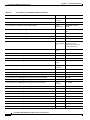
Table 1-2
Champ Connector Pin Assignments—Side-A EIA, Connectors J8 and J9; Side-B EIA,
Connectors J21 and J22 (continued)
Signal
Pin
Signal
Pin
Ring Port 16
16
Tip Port 16
48
Ring Port 17
17
Tip Port 17
49
Ring Port 18
18
Tip Port 18
50
Ring Port 19
19
Tip Port 19
51
Ring Port 20
20
Tip Port 20
52
Ring Port 21
21
Tip Port 21
53
Ring Port 22
22
Tip Port 22
54
Ring Port 23
23
Tip Port 23
55
Ring Port 24
24
Tip Port 24
56
Ring Port 25
25
Tip Port 25
57
Ring Port 26
26
Tip Port 26
58
Ring Port 27
27
Tip Port 27
59
Ring Port 28
28
Tip Port 28
60
Unused
29
Unused
61
Unused
30
Unused
62
Unused
31
Unused
63
Unused
32
Unused
64
Table 1-3 lists the Champ connector pin assignments and the corresponding EIA connector mapping for
connectors J10 and J11 on the EIA installed on the A side, and connectors J23 and J24 on the EIA
installed on the B side.
Table 1-3
Champ Connector Pin Assignments—Side-A EIA, Connectors J10 and J11; Side-B EIA,
Connectors J23 and J24
Signal
Pin
Signal
Pin
Ring Port 29
1
Tip Port 29
33
Ring Port 30
2
Tip Port 30
34
Ring Port 31
3
Tip Port 31
35
Ring Port 32
4
Tip Port 32
36
Ring Port 33
5
Tip Port 33
37
Ring Port 34
6
Tip Port 34
38
Ring Port 35
7
Tip Port 35
39
Ring Port 36
8
Tip Port 36
40
Ring Port 37
9
Tip Port 37
41
Ring Port 38
10
Tip Port 38
42
Ring Port 39
11
Tip Port 39
43
Ring Port 40
12
Tip Port 40
44
Cisco ONS 15310-MA SDH Reference Manual, Release 9.1 and Release 9.2
1-16
78-19417-01
Chapter 1
Cisco ONS 15310-MA SDH Shelf Assembly Hardware
Cable Description and Installation
Table 1-3
Champ Connector Pin Assignments—Side-A EIA, Connectors J10 and J11; Side-B EIA,
Connectors J23 and J24 (continued)
Signal
Pin
Signal
Pin
Ring Port 41
13
Tip Port 41
45
Ring Port 42
14
Tip Port 42
46
Ring Port 43
15
Tip Port 43
47
Ring Port 44
16
Tip Port 44
48
Ring Port 45
17
Tip Port 45
49
Ring Port 46
18
Tip Port 46
50
Ring Port 47
19
Tip Port 47
51
Ring Port 48
20
Tip Port 48
52
Ring Port 49
21
Tip Port 49
53
Ring Port 50
22
Tip Port 50
54
Ring Port 51
23
Tip Port 51
55
Ring Port 52
24
Tip Port 52
56
Ring Port 53
25
Tip Port 53
57
Ring Port 54
26
Tip Port 54
58
Ring Port 55
27
Tip Port 55
59
Ring Port 56
28
Tip Port 56
60
Unused
29
Unused
61
Unused
30
Unused
62
Unused
31
Unused
63
Unused
32
Unused
64
Table 1-4 lists the Champ connector pin assignments and the corresponding EIA mapping for connectors
J12 and J13 on the A-side EIA, and connectors J25 and J26 on the B-side EIA.
Table 1-4
Champ Connector Pin Assignments—Side-A EIA, Connectors J12 and J13; Side-B EIA,
Connectors J25 and J26
Signal
Pin
Signal
Pin
Not used
1
Not used
33
Not used
2
Not used
34
Ring Port 57
3
Tip Port 57
35
Ring Port 58
4
Tip Port 58
36
Ring Port 59
5
Tip Port 59
37
Ring Port 60
6
Tip Port 60
38
Ring Port 61
7
Tip Port 61
39
Ring Port 62
8
Tip Port 62
40
Ring Port 63
9
Tip Port 63
41
Cisco ONS 15310-MA SDH Reference Manual, Release 9.1 and Release 9.2
78-19417-01
1-17
Chapter 1
Cisco ONS 15310-MA SDH Shelf Assembly Hardware
Cable Description and Installation
Table 1-4
Champ Connector Pin Assignments—Side-A EIA, Connectors J12 and J13; Side-B EIA,
Connectors J25 and J26 (continued)
Signal
Pin
Signal
Pin
Unused
10
Unused
42
Unused
11
Unused
43
Unused
12
Unused
44
Unused
13
Unused
45
Unused
14
Unused
46
Unused
15
Unused
47
Unused
16
Unused
48
Unused
17
Unused
49
Unused
18
Unused
50
Unused
19
Unused
51
Unused
20
Unused
52
Unused
21
Unused
53
Unused
22
Unused
54
Unused
23
Unused
55
Unused
24
Unused
56
Unused
25
Unused
57
Unused
26
Unused
58
Unused
27
Unused
59
Unused
28
Unused
60
Unused
29
Unused
61
Unused
30
Unused
62
Unused
31
Unused
63
Unused
32
Unused
64
1.8.5 Alarm Cable Installation
The alarm cables attach to the rear of the ONS 15310-MA SDH at the ALARM In and ALARM Out
ports. The other ends of the cables plug into the alarm-collection equipment. Terminate the ends of these
cables according to local site practice. The pins on the ALARM In and ALARM Out ports correspond
to the 32 external alarm inputs and the 8 external alarm outputs (controls) that you can define using
Cisco Transport Controller (CTC).
Table 1-5 shows the default input alarm pinouts and the corresponding alarm numbers assigned to each
port. Refer to this table when connecting alarm cables to the ONS 15310-MA SDH.
Cisco ONS 15310-MA SDH Reference Manual, Release 9.1 and Release 9.2
1-18
78-19417-01
Chapter 1
Cisco ONS 15310-MA SDH Shelf Assembly Hardware
Cable Description and Installation
Table 1-5
Default Alarm Pin Assignments—Inputs
DB-37 Pin Number
Function
DB-37 Pin Number
Function
1
Alarm 1
20
Alarm 18
2
Alarm 2
21
Alarm 19
3
Alarm 3
22
Alarm 20
4
Alarm 4
23
Alarm 21
5
Alarm 5
24
Alarm 22
6
Alarm 6
25
Alarm 23
7
Alarm 7
26
Alarm 24
8
Alarm 8
27
Common 17–24
9
Common 1–8
28
Alarm 25
10
Alarm 9
29
Alarm 26
11
Alarm 10
30
Alarm 27
12
Alarm 11
31
Alarm 28
13
Alarm 12
32
Alarm 29
14
Alarm 13
33
Alarm 30
15
Alarm 14
34
Alarm 31
16
Alarm 15
35
Alarm 32
17
Alarm 16
36
Common 25–32
18
Common 9–16
37
N/C
19
Alarm 17
—
—
Table 1-6 shows the default output alarm pinouts and the corresponding alarm numbers assigned to each
port. Refer to this table when connecting alarm cables to the ONS 15310-MA SDH.
Table 1-6
Default Alarm Pin Assignments—Outputs
DB-25 Pin Number
Function
DB-25 Pin Number
Function
1
Out 1+
14
Out 2+
2
Out 1–
15
Out 2–
3
—
16
Out 3+
4
—
17
Out 3–
5
—
18
Out 4+
6
—
19
Out 4–
7
—
20
Out 5+
8
—
21
Out 5–
9
—
22
Out 6+
10
—
23
Out 6–
11
—
24
Out 7+
Cisco ONS 15310-MA SDH Reference Manual, Release 9.1 and Release 9.2
78-19417-01
1-19
Chapter 1
Cisco ONS 15310-MA SDH Shelf Assembly Hardware
Cable Description and Installation
Table 1-6
Default Alarm Pin Assignments—Outputs (continued)
DB-25 Pin Number
Function
DB-25 Pin Number
Function
12
Out 8+
25
Out 7–
13
Out 8–
—
—
For information about provisioning alarms for external devices, refer to Chapter,
“Manage alarms”, Section, “Provision External Alarms and Controls” in the Cisco ONS 15310-MA SDH
Procedure Guide.
1.8.6 BITS Cable Installation
The BITS clock cable (terminated with a DB-9 connector or with a DB9BIT=BB9 to wire wrap adapter)
attaches to the BITS port on the ONS 15310-MA SDH. The other end of the cable plugs into the BITS
clock, terminate this end of the cable according to local site practice. In case the DB9BIT=BB9 to wire
wrap adapter is used on the ONS 15310-MA, the cable shield must be wire-wrapped to the GND pin of
the wire wrap adapter.
The 15310-MA SDH has one BITS input and one BITS output. The BITS inputs and outputs have
corresponding pins on the DB-9 BITS ports. When connecting BITS cable to the ONS 15310-MA SDH,
see Table 1-7 for the BITS cable pin assignments.
Note
Table 1-7
BITS Cable Pin Assignments
DB-9 Pin
Number
Function
1
BITS Output+
2
BITS Output–
3
—
4
—
5
—
6
BITS Input+
7
BITS Input–
8
—
9
—
Refer to Telcordia SR-NWT-002224 for rules about how to provision timing references.
1.8.7 UDC Cable Installation
The 64K, EIA/TIA-232 user data channel (UDC) interface provides F1 and F2 byte input and output.
When connecting the UDC cable to the ONS 15310-MA SDH, see Table 1-8 for the UDC cable pin
assignments. Unshielded twisted-pair #22 or #24 AWG wire is required for the UDC ports.
Cisco ONS 15310-MA SDH Reference Manual, Release 9.1 and Release 9.2
1-20
78-19417-01
Chapter 1
Cisco ONS 15310-MA SDH Shelf Assembly Hardware
Cable Routing and Management
Table 1-8
UDC Cable Pin Assignments
RJ-45 Pin
Number
RS-232/64K
Mode
1
TX +
2
TX –
3
RX +
4
—
5
—
6
RX –
7
—
8
—
1.9 Cable Routing and Management
Two types of cable management brackets are available for the ONS 15310-MA SDH shelf assembly: the
standard bracket, which ships with the ONS 15310-MA SDH ship kit, and the extended bracket, which
ships as a separate orderable part. You can install either bracket under the shelf assembly.
1.9.1 Standard Cable Management Bracket
The standard cable management bracket has one area in the rear that can be used for routing cables.
Fiber-optic cable can be routed through the rear trough of the bracket. Ethernet cables can be passed
through the front of the bracket to be bundled and secured using tie-wraps or other site-specific
materials.
Figure 1-12 shows the installation of the standard cable management bracket.
Cisco ONS 15310-MA SDH Reference Manual, Release 9.1 and Release 9.2
78-19417-01
1-21
Chapter 1
Cisco ONS 15310-MA SDH Shelf Assembly Hardware
Cable Routing and Management
Installing the Standard Cable Management Bracket
151577
Figure 1-12
1.9.2 Extended Cable Management Bracket
The extended cable management bracket has two areas that can be used for routing cables, one in the
front and one in the rear. Fiber-optic cables can be routed through the smaller front trough, and Ethernet
cables can be routed through the larger rear trough.
Figure 1-13 shows the installation of the extended cable management bracket.
Cisco ONS 15310-MA SDH Reference Manual, Release 9.1 and Release 9.2
1-22
78-19417-01
Chapter 1
Cisco ONS 15310-MA SDH Shelf Assembly Hardware
Fan-Tray Assembly
Installing the Extended Cable Management Bracket
151578
Figure 1-13
1.10 Fan-Tray Assembly
The fan-tray assembly is located at the top of the ONS 15310-MA SDH shelf assembly, under the air
filter, rear exhaust, and air inlet. The fan tray is a removable drawer that holds four fans, the fan-control
circuitry, and the fuse-control circuitry for the ONS 15310-MA SDH. After you install the fan tray, you
should only need to access it if a fan failure occurs.
The new fan-tray assembly (FTA2) has a fuse-control circuitry that is capable of blowing a low-current
fuse (1/4-A to 1/2-A). This is useful when you are using power distribution equipment that has a low
current fuse connected in parallel with the main fuse to help detect any failures in the main fuse. The
fuse-control circuitry independently draws a short current (approximately 900 mA) for about 0.7 seconds
Cisco ONS 15310-MA SDH Reference Manual, Release 9.1 and Release 9.2
78-19417-01
1-23
Chapter 1
Cisco ONS 15310-MA SDH Shelf Assembly Hardware
Fan-Tray Assembly
every 15 minutes (at 24 degrees Celsius or 120 degrees Fahrenheit), alternating between power supply
inputs A and B. This allows the ONS 15310-MA SDH to blow the low current fuse when there is a failure
or loss of the main fuse and report an alarm (FAN alarm).
The front of the fan-tray assembly has CRIT, MAJ, and MIN alarm LEDs that illuminate if a Critical,
Major, or Minor alarm is present anywhere on the ONS 15310-MA SDH assembly.
1.10.1 Fan Speed and Power Requirements
Fan speed is controlled by temperature sensors on the 15310E-CTX-K9 card. The sensors measure the
input air temperature at the fan-tray assembly. Fan speed options are low, medium, and high.
1.10.2 Fan Failure
If one or more fans fail on the fan-tray assembly, replace the entire assembly. You cannot replace
individual fans. The red Fan Fail LED on the front of the fan tray illuminates when one or more fans fail.
For fan-tray replacement instructions, refer to the Cisco ONS 15310-MA SDH Troubleshooting Guide.
The red Fan Fail LED is unlit after you install a working fan tray.
Note
The red Fan Fail LED on the front of the fan tray illuminates when only one power source is connected
to the chassis, or any fuse blows.
1.10.3 Air Filter
The ONS 15310-MA SDH contains a reusable air filter (15310-MA SDH-FTF) that is installed above
the fan-tray assembly. The reusable filter is made of a gray, open-cell, polyurethane foam that is specially
coated to provide fire and fungi resistance. Spare filters should be kept in stock.
Caution
Do not operate an ONS 15310-MA SDH without the mandatory fan-tray air filter.
1.10.4 Orderwire
Orderwire allows a crafts person to plug a phone set into an ONS 15310-MA SDH and communicate
with crafts people working at other ONS 15310-MA SDH nodes or other facility equipment. The
orderwire is a pulse code modulation (PCM) encoded voice channel that uses E1 or E2 bytes in the
MSOH and in the regenerator section overhead.
The FTA allows simultaneous either local (RSOH signal) or express (MSOH signal) orderwire channels
on an SDH ring or particular optics facility. Express orderwire also allows communication through
regeneration sites when the regenerator is not a Cisco device.
You can provision orderwire functions with CTC similar to the current provisioning model for DCC
channels. In CTC, you provision the orderwire communications network during ring turn-up so that all
network elements (NEs) on the ring can communicate with one another. Orderwire terminations (that is,
the optics facilities that receive and process the orderwire channels) are provisionable. Both express and
local orderwire can be configured as on or off on a particular SDH facility. The ONS 15310-MA SDH
supports up to four orderwire channel terminations per shelf. This allows linear, single ring, dual ring,
Cisco ONS 15310-MA SDH Reference Manual, Release 9.1 and Release 9.2
1-24
78-19417-01
Chapter 1
Cisco ONS 15310-MA SDH Shelf Assembly Hardware
Fan-Tray Assembly
and small hub-and-spoke configurations. Keep in mind that orderwire is not protected in ring topologies
such as multiplex section-shared protection ring (MS-SPRing) and subnetwork connection protection
(SNCP).
Note
Caution
The Cisco ONS 15310-MA SDH Orderwire functionality is compatible with Cisco ONS 15454
Orderwire functionality.
Do not configure orderwire loops. Orderwire loops cause feedback that disables the orderwire channel.
The ONS 15310-MA SDH implementation of both local and express orderwire is broadcast in nature.
The line acts as a party line. Anyone who picks up the orderwire channel can communicate with all other
participants on the connected orderwire subnetwork. The local orderwire party line is separate from the
express orderwire party line. Up to four STM-N facilities for each local and express orderwire are
provisionable as orderwire paths.
The FTA supports selective dual tone multifrequency (DTMF) dialing for telephony connectivity, which
causes specific or all ONS 15310-MA SDH FTAs on the orderwire subnetwork to “ring.” The
ringer/buzzer resides on the FTA. There is also a “ring” LED that mimics the FTA ringer. It flashes when
a call is received on the orderwire subnetwork. A party line call is initiated by pressing *0000 on the
DTMF pad.
The orderwire ports are standard RJ-11 receptacles. The pins on the orderwire ports correspond to the
tip and ring orderwire assignments.
Table 1-9 describes the orderwire pin assignments.
Table 1-9
Orderwire Pin Assignments
RJ-11 Pin Number
Description
1
Four-wire receive ring
2
Four-wire transmit tip
3
Two-wire ring
4
Two-wire tip
5
Four-wire transmit ring
6
Four-wire receive tip
When provisioning the orderwire subnetwork, make sure that an orderwire loop does not exist. Loops
cause oscillation and an unusable orderwire channel.
Figure 1-14 shows the standard RJ-11 connectors used for orderwire ports. Use a shielded RJ-11 cable.
Cisco ONS 15310-MA SDH Reference Manual, Release 9.1 and Release 9.2
78-19417-01
1-25
Chapter 1
Cisco ONS 15310-MA SDH Shelf Assembly Hardware
Cards and Slots
Figure 1-14
RJ-11 Cable Connector
61077
RJ-11
Pin 1
Pin 6
1.11 Cards and Slots
Caution
Always use the supplied ESD wristband when working with a powered ONS 15310-MA SDH. For
detailed instructions on how to wear the ESD wristband, refer to the Cisco ONS Electrostatic Discharge
(ESD) and Grounding Guide.
The ONS 15310-MA SDH has six card slots. Slots 3 and 4 are dedicated to the common-control
(15310E-CTX-K9) cards. Slots 1, 2, 5, and 6 can accommodate the following traffic cards:
•
Ethernet: CE-100T-8 card, ML-100T-8, CE-MR-6 card
•
Electrical: E1_21_E3_DS3_3 card, E1_63_E3_DS3_3 card
These cards have plugs at the rear of the card. When the ejectors are fully closed, the card plugs into the
assembly backplane.
When no card is installed in a card slot, a filler card should be installed. Use a 15310E-CTX-K9 filler
card in empty 15310E-CTX-K9 slots (Slots 3 and 4), and an expansion filler card in empty traffic card
slots (Slots 1, 2, 5, and 6).
Cisco ONS 15310-MA SDH Reference Manual, Release 9.1 and Release 9.2
1-26
78-19417-01
Chapter 1
Cisco ONS 15310-MA SDH Shelf Assembly Hardware
Cards and Slots
Figure 1-15 shows card installation for the ONS 15310-MA SDH.
Installing a Card in an ONS 15310-MA SDH
144703
Figure 1-15
Table 1-10 lists the number of ports, line rates, connector options, and connector locations for
ONS 15310-MA SDH electrical, Ethernet, and optical interfaces.
Table 1-10
Port Line Rates, Connector Types, and Locations
Interface
Ports
Line Rate per Port
Connector
Type
Connector Location
E1
21/63
2.048 Mbps
Champ
Rear of the 15310-MA
SDH shelf assembly
DS-3
3
44.736 Mbps
BNC
Rear of the 15310-MA
SDH shelf assembly
E3
3
34 Mbps
BNC
Rear of the 15310-MA
SDH shelf assembly
STM1/STM4/STM16
2
155.52 Mbps (VC4)
LC
15310E-CTX-K9 card
faceplate
RJ-45
CE-100T-8 card faceplate
622.08 Mbps
(VC4-4c)
Ethernet (CE-100T-8 card)1 8
10/100 Mbps
Cisco ONS 15310-MA SDH Reference Manual, Release 9.1 and Release 9.2
78-19417-01
1-27
Chapter 1
Cisco ONS 15310-MA SDH Shelf Assembly Hardware
Cards and Slots
Table 1-10
Port Line Rates, Connector Types, and Locations (continued)
Line Rate per Port
Connector
Type
Connector Location
Ethernet (ML-100T-8 card)2 8
10/1000 Mbps
RJ-45
Ethernet (CE-MR-6 card)
10/100/1000 Mbps
LC (SFP), Faceplate
Copper
(SFP)-RJ4
5
Interface
Ports
6
ML-100T-8 card faceplate
1. The CE-100T-8 card with PID 15310-CE-100T-8 is not compatible with the ONS 15310-MA SDH. The 15310-P-CE-100T-8
is compatible with the ONS 15310-MA SDH shelf assemblies.
2. The ML-100T-8 card with PID 15310-ML-100T-8 is not compatible with the ONS 15310-MA SDH.
The 15310-P-ML-100T-8 is compatible with the ONS 15310-MA SDH shelf assemblies.
Cisco ONS 15310-MA SDH Reference Manual, Release 9.1 and Release 9.2
1-28
78-19417-01
CH A P T E R
2
Card Reference
This chapter describes the Cisco ONS 15310-MA SDH cards. It includes descriptions and block
diagrams for each card. For specifications, see Appendix A, “Specifications.”For card installation and
turn-up procedures, refer to the Cisco ONS 15310-MA SDH Procedure Guide.
Chapter topics include:
Note
•
2.1 Card Summary and Compatibility, page 2-1
•
2.2 15310E-CTX-K9 Card, page 2-4
•
2.3 CE-100T-8 Card, page 2-6
•
2.4 CE-MR-6 Card, page 2-9
•
2.5 ML-100T-8 Card, page 2-12
•
2.6 E1_21_E3_DS3_3 and E1_63_E3_DS3_3 Cards, page 2-16
•
2.7 Filler Cards, page 2-18
•
2.8 SFP Modules, page 2-19
The I-Temp symbol is located on the faceplate of an I-Temp compliant card. A card without this symbol
is C-Temp compliant.
2.1 Card Summary and Compatibility
The Cisco ONS 15310-MA SDH uses a common-control card (the 15310E-CTX-K9) and a combination
of Ethernet cards (CE-100T-8, CE-MR-6, and ML-100T-8) and electrical cards (E1_21_E3_DS3_3 and
E1_63_E3_DS3_3). The 15310E-CTX-K9 card provides optical connections for the ONS 15310-MA
SDH.
This section provides a card summary. Figure 2-1 shows the ONS 15310-MA SDH fully populated with
cards.
Cisco ONS 15310-MA SDH Reference Manual, Release 9.1 and Release 9.2
78-19417-01
2-1
Chapter 2
Card Reference
Card Summary and Compatibility
Figure 2-1
ONS 15310-MA SDH with Cards Installed
15310-MA SDH
E1_63_
E3_DS3_3
E1
E1_63_
E3_DS3_3
E1_63_
E3_DS3_3
E1
E1
271781
E1
E1_63_
E3_DS3_3
2.1.1 Card Summary
The ONS 15310-MA SDH cards are summarized in Table 2-1.
Table 2-1
ONS 15310-MA SDH Cards and Descriptions
Card
Compatible
Platform(s) Description
15310E-CTX-K9
MA
The 15310E-CTX-K9 card serves as the
common control and central switching element
for the ONS 15310-MA SDH.
See the “2.2 15310E-CTX-K9 Card”
section on page 2-4.
CE-100T-8
MA
The CE-100T-8 card provides eight RJ-45
10/100-Mbps Ethernet ports.
See the “2.3 CE-100T-8 Card” section
on page 2-6.
CE-MR-6
MA
The CE-MR-6 card provides six
10/100/1000-Mbps Gigabit Ethernet ports.
See the “2.4 CE-MR-6 Card” section
on page 2-9.
ML-100T-8
MA
The ML-100T-8 Ethernet card provides eight
ports of 10/100 Ethernet-encapsulated traffic
into SDH VC4/STM-1 payloads.
See the “2.5 ML-100T-8 Card”
section on page 2-12.
For Additional Information...
Cisco ONS 15310-MA SDH Reference Manual, Release 9.1 and Release 9.2
2-2
78-19417-01
Chapter 2
Card Reference
Card Summary and Compatibility
Table 2-1
ONS 15310-MA SDH Cards and Descriptions (continued)
Card
Compatible
Platform(s) Description
For Additional Information...
E1_21_E3_DS3_3 and
E1_63_E3_DS3_3
MA SDH
The E1_21_E3_DS3_3 and E1_63_E3_DS3_3
cards provide 21 and 63 ITU-Compliant G.703
E1 ports, respectively, as well as three E3/DS3
ports.
Filler Card (Traffic Slot)
MA
The FILLER card is used to fill unused traffic
See the “2.7 Filler Cards” section on
card slots in the ONS 15310-MA SDH shelves. page 2-18.
The Cisco Transport Controller (CTC) graphical
user interface (GUI) detects the filler card.
Filler Card
(15310E-CTX-K9 Slot)
MA
The CTX FILLER card is used to fill unused
15310E-CTX-K9 card slots in the
ONS 15310-MA SDH shelf. CTC detects the
filler card.
SFP Modules
MA
Small Form-factor Pluggables (SFPs) are
See the “2.8 SFP Modules” section on
integrated fiber-optic transceivers that provide
page 2-19
high-speed serial links from a port or slot to the
network.
See the “2.6 E1_21_E3_DS3_3 and
E1_63_E3_DS3_3 Cards” section on
page 2-16.
See the “2.7 Filler Cards” section on
page 2-18.
2.1.2 Card Compatibility
Table 2-2 lists CTC software release compatibility for each ONS 15310-MA SDH card. In the table,
“Yes” means that the card is compatible with the listed software release.
.
Table 2-2
ONS 15310-MA SDH Software Release Compatibility Per Card
Card
R9.1 and R9.2
15310E-CTX-K9
CE-100T-8 Card
Yes
1
CE-MR-6 Card
ML-100T-8 Card
Yes
Yes
2
Yes
E1_21_E3_DS3_3
Yes
E1_63_E3_DS3_3
Yes
FILLER Card
Yes
CTX FILLER Card
Yes
1. The CE-100T-8 card with product ID (PID) 15310-CE-100T-8 is not
compatible with the ONS 15310-MA SDH. 15310-P-CE-100T-8 is compatible
with the ONS 15310-MA SDH shelf assembly.
2. The ML-100T-8 card with PID 15310-ML-100T-8 is not compatible with the
ONS 15310-MA SDH shelf assembly. 15310-P-ML-100T-8 is compatible with
the ONS 15310-MA SDH shelf assembly.
Cisco ONS 15310-MA SDH Reference Manual, Release 9.1 and Release 9.2
78-19417-01
2-3
Chapter 2
Card Reference
15310E-CTX-K9 Card
2.2 15310E-CTX-K9 Card
The 15310E-CTX-K9 card, for use with the ONS 15310-MA SDH, is a fully nonblocking cross-connect
card that operates in either a simplex or duplex (redundant) configuration. It performs system
initialization, provisioning, alarm reporting, maintenance, diagnostics, IP address detection/resolution,
SDH DCC termination, system fault detection, and cross-connect maintenance and management for the
ONS 15310-MA SDH. The card also provides the circuitry for the STM1/STM4/STM16 interfaces, and
ensures that the system maintains timing with SETS stability.
Caution
If the system loses power or the 15310E-CTX-K9 card is reset, you must reset the ONS 15310-MA SDH
clock unless the node has been previously provisioned to use Simple Network Time Protocol (SNTP) to
update the clock over the LAN.
Figure 2-2 shows the 15310E-CTX-K9 card faceplate and block diagram.
15310E-CTX-K9 Faceplate and Block Diagram
PLL
Backplane Connectors
REFCLK_OUT OCXO
TIMING
MOD
LIU
SCL I/F
SFP1
XPT
SW
SFP1
OCN I/F
REFCLK_IN
VXCO
XPT
SW
XPT and SFP Control/Status
From Nile2 CPLD
ASIC
ATA I/F
Compact
FLASH
CPU I/F
FLASH
Front Panel
STS1 XC
TU XC
VT XC
DDR
SDRAM
BUS
FANOUT
FPGA
FPGA
LED
CPLD
ENWT SW
DC/DC
PROCESSOR
I2C
TEMP
SFP1/2
IDPROM
RJ45
FP
CRAFT
RJ45
FP
ENET
145768
Figure 2-2
Cisco ONS 15310-MA SDH Reference Manual, Release 9.1 and Release 9.2
2-4
78-19417-01
Chapter 2
Card Reference
15310E-CTX-K9 Card
2.2.1 System Cross-Connect
The 15310E-CTX-K9 card provides:
•
2016 VC12 ports. That is, 1008 VC-12 Cross-connections (1008X1008)
•
96 VC3 ports. That is, 48 VC-3 Cross-Connections (48X48)
•
128 VC4 ports. That is, 64 VC-4 Cross -Connections (64X64)
2.2.2 15310E-CTX-K9 Card Side Switches
The 15310E-CTX-K9 supports errorless side switches (less than a 50-ms impact to any traffic) when the
switch is initiated through software, through either a soft-reset or a software upgrade where there is no
FPGA or firmware upgrade. A side switch means switching from a 15310E-CTX-K9 on one side of the
shelf to the redundant 15310E-CTX-K9 on the other side of the shelf.
2.2.3 15310E-CTX-K9 Optical Interfaces
There are two PPM (SFP) slots on the 15310E-CTX-K9 faceplate to provide optical interfaces. (PPM is
the graphical user interface term for SFP.) Each slot can contain a one-port PPM. Cisco-qualified PPMs
can be single-rate (STM1, STM4, or STM16) or multirate (STM1/STM4). Single-rate PPMs are
autoprovisioned when they are installed, but multirate PPMs must be provisioned. This behavior can be
controlled by NE defaults.
Note
To provision, edit, or delete PPM ports, refer to the “Change Port Settings” chapter in the
Cisco ONS 15310-MA SDH Procedure Guide. For more information about PPM/SFP hardware, see the
“2.8 SFP Modules” section on page 2-19.
Note
CTX-2500 only supports STM1-E Electrical SFP.
2.2.4 15310E-CTX-K9 Card-Level Indicators
The 15310E-CTX-K9 card has four card-level LEDs, described in Table 2-3.
Table 2-3
15310E-CTX-K9 Card-Level Indicators
Card-Level LEDs
Description
FAIL LED (Red)
The red FAIL LED indicates that the card processor is not ready or that a
catastrophic software failure occurred on the card. As part of the boot
sequence, the FAIL LED turns on and flashes until the software deems the
card operational.
Cisco ONS 15310-MA SDH Reference Manual, Release 9.1 and Release 9.2
78-19417-01
2-5
Chapter 2
Card Reference
CE-100T-8 Card
Table 2-3
15310E-CTX-K9 Card-Level Indicators (continued)
Card-Level LEDs
Description
ACT/STBY LED
(Green/Amber)
The ACT/STBY LED is green if the card is the active 15310E-CTX-K9 card.
It is amber if the card is the standby card.
SYNC LED
(Green/Amber)
The SYNC LED is green if the 15310E-CTX-K9 card detects both a primary
and secondary clock reference. It is amber if the card detects only a single
clock reference.
2.2.5 15310E-CTX-K9 Port-Level Indicators
Two bicolor LEDs show the status per port (Ports 1 and 2). The port LED is green if the port is available
to carry traffic and is provisioned as in-service. The port LED is red if there is a signal failure or loss of
signal on the port.
2.3 CE-100T-8 Card
This section describes the features and functions of the Layer 1 Ethernet card, the CE-100T-8.
Note
Caution
The CE-100T-8 card with PID 15310-CE-100T-8 is not compatible with the ONS 15310-MA SDH.
The 15310-P-CE-100T-8 is compatible with the ONS 15310-MA SDH shelf assembly. If you install a
15310-CE-100T-8 in an ONS 15310-MA SDH shelf assembly, you will receive a mismatched equipment
alarm (mismatchofEquipment). You can view the PID under the node view Inventory tab in CTC.
Do not install CE-100T-8 and ML-100T-8 cards in OSP.
The CE-100T-8 card maps 8-port 10/100-Mbps Ethernet-encapsulated traffic into SDH payloads,
making use of low-order (VC12) virtual concatenation (VCAT), high-order (VC3, VC4) VCAT, generic
framing procedure (GFP), and Point-to-Point Protocol/high-level data link control (PPP/HDLC) framing
protocols. It also supports the link capacity adjustment scheme (LCAS), which allows hitless dynamic
adjustment of SDH link bandwidth. The CE-100T-8 card provides eight RJ-45 10/100-Mbps Ethernet
ports on the faceplate of the card. An inactive RJ-11 console port is also on the faceplate.
The circuit types supported are:
Note
•
VC3 and VC4 CCAT
•
VC3-Nv VCAT (N = 1–3)
•
VC3-Nv LCAS (N = 1–3)
•
VC3-2v software LCAS (SW-LCAS) (compatible with ML-Series cards only)
•
VC12-Nv VCAT (N = 1-63)
•
VC12-Nv LCAS(N = 1-63)
The SW-LCAS is not supported on CE-100T-8 cards for interoperation with the CE-MR-6 and
ML-MR-10 cards.
Cisco ONS 15310-MA SDH Reference Manual, Release 9.1 and Release 9.2
2-6
78-19417-01
Chapter 2
Card Reference
CE-100T-8 Card
Each 10/100 Ethernet port can be mapped to an SDH channel in increments of VC12 or VC3 granularity.
There are eight backend packet-over-SDH (POS) ports (VCAT groups [VCGs]) available on the
ML-100T-8 card. Additionally, the CE-100T-8 card supports packet processing, classification, quality of
service (QoS)-based queuing, and traffic scheduling.
Figure 2-3 shows the CE-100T-8 card faceplate and block diagram.
Figure 2-3
CE-100T-8 Faceplate and Block Diagram
CE-100T-8
LINK
1
ACT
8x
RJ45
8
Octal
PHY
8
SMII
Packet
Processor
(QoS
and
Queuing)
LINK
2
ACT
8
SMII
Mux/
Demux 622 Mbit
7
SMII
LINK
3
ACT
LINK
4
ACT
LINK
5
ACT
LINK
6
ACT
SMII
SMII
to MII
Adapter
POS
Mapper
and
VCAT/
LCAS
Engine
155 Mbit
B
a
c
k
p
l
a
n
e
BTC48
Intercard
Ethernet Links
PHY
MII
CPU Complex
271811
ACTIVE
POS
Mapper
and
VCAT/
LCAS 155 Mbit
Engine
LINK
7
ACT
LINK
8
ACT
The following paragraphs describe the general functions of the CE-100T-8 card and relate it to the block
diagram in Figure 2-3.
In the ingress direction (Ethernet-to-SDH), an octal PHY, which performs all of the physical layer
interface functions for 10/100-Mbps Ethernet, sends the frame to the packet processor for queuing in the
respective packet buffer memory. The packet processor performs packet processing, packet switching,
and classification. The Ethernet frames are then passed over SMII channels to the POS mappers, where
Ethernet traffic is terminated and is encapsulated using the PPP/HDLC or GFP framing protocols. The
encapsulation method is selected on a per-port basis. The encapsulated Ethernet frames are then mapped
into a configurable number of VCAT low-order and high-order payloads, such as VC12 synchronous
payload envelope (SPE), VC3 SPE, or a contiguous concatenated (CCAT) payload such as VC4 SPE. Up
to 63 VC12 SPEs or three VC3 SPEs can be virtually concatenated.
Cisco ONS 15310-MA SDH Reference Manual, Release 9.1 and Release 9.2
78-19417-01
2-7
Chapter 2
Card Reference
CE-100T-8 Card
The SPE from each POS mapper (up to VC4) carrying encapsulated Ethernet frames are passed onto the
multiplexer/demultiplexer (mux/demux) next, where the VC4 frames from both POS mappers are
multiplexed to form an VC4-4 frame for transport over the SDH network by means of the Bridging
Transmission Convergence (BTC-48) application-specific integrated circuit (ASIC).
Note
Although the VC4 frames are multiplexed into an VC4-4 frame, the frame carries at most an VC4-2c
payload, leaving half of the VC4-4 bandwidth free.
In the egress direction (SDH-to-Ethernet), the mux/demux extracts the first and second VC4 SPEs from
the VC4-4 frame it receives from the BTC-48 before sending them to the POS mappers. The VC4 SDH
SPE carrying GFP or PPP/HDLC encapsulated Ethernet frames are then extracted and buffered in the
external memory of the POS mappers. This memory is used for providing alignment and differential
delay compensation for the received low/high order virtual concatenated payloads. When alignment and
delay compensation are complete, the Ethernet frames are decapsulated with one of the framing
protocols (GFP or PPP/HDLC). Decapsulated Ethernet frames are then passed onto the packet processor
for QoS queuing and traffic scheduling. The network processor switches the frame to one of the
corresponding PHY channels and then onto the Ethernet port for transmission to the external clients.
With regard to QoS, the VLAN class-of-service (CoS) threshold (value 0 to 7, default 7) and the IP
type-of-service (ToS) threshold (value 0 to 255, default 255) on incoming Ethernet packets are both
available for priority queuing. These thresholds are provisionable through CTC, TL1, and Cisco
Transport Manager (CTM). CoS takes precedence over ToS unless the CoS threshold is set to the default
of 7. This threshold value does not prioritize any packets based on CoS, so ToS is used. The value
configured is a threshold and any value greater than that value is set as a priority. For example, if a CoS
of 5 is set as the threshold, only CoS values of 6 and 7 would be set to priority.
2.3.1 CE-100T-8 Card-Level Indicators
The CE-100T-8 card faceplate has two card-level LED indicators, described in Table 2-4.
Table 2-4
CE-100T-8 Card-Level Indicators
Card-Level LEDs
Description
SF LED (Red)
The red FAIL LED indicates that the card processor is not ready or that a
catastrophic software failure occurred on the CE-100T-8 card. As part of the
boot sequence, the FAIL LED blinks until the software deems the card
operational, then it turns off.
ACT LED (Green)
The ACT LED provides the operational status of the CE-100T-8. When the
ACT LED is green, it indicates that the CE-100T-8 card is active and the
software is operational; otherwise, it is off.
2.3.2 CE-100T-8 Port-Level Indicators
The CE-100T-8 card has two LEDs embedded into each of the eight Ethernet-port RJ-45 connectors. The
LEDs are described in Table 2-5.
Cisco ONS 15310-MA SDH Reference Manual, Release 9.1 and Release 9.2
2-8
78-19417-01
Chapter 2
Card Reference
CE-MR-6 Card
Table 2-5
CE-100T-8 Port-Level Indicators
Port-Level Indicators
Description
ACT LED (Amber)
A steady amber LED indicates a link is detected, but there is an issue
inhibiting traffic. A blinking amber LED means traffic is flowing.
LINK LED (Green)
A steady green LED indicates that a link is detected, but there is no
traffic. A blinking green LED flashes at a rate proportional to the level
of traffic being received and transmitted over the port.
Both ACT and LINK LED
OFF
Unlit green and amber LEDs indicate no traffic.
2.4 CE-MR-6 Card
This section describes the features and functions of the CE-MR-6 Ethernet card. This card is compatible
with the Cisco ONS 15310-MA SDH.
The CE-MR-6 card provides six IEEE 802.3-compliant 10/100/1000-Mbps Gigabit Ethernet ports at the
ingress. At the egress, the CE-MR-6 card provides an integrated Ethernet over SDH mapper with six
virtual ports to transfer Ethernet packets over an SDH network.
The CE-MR-6 card uses pluggable Small Form-Factor Pluggable Interface Converters (SFPs) to
transport Ethernet traffic over an SDH network. SFP modules are offered as separate orderable products
for flexibility. For details, see the “2.8 SFP Modules” section on page 2-19.
The Ethernet frames are encapsulated using the ITU-T generic framing procedure (GFP) [with or
without cyclic redundancy check (CRC)] or LAN extension (LEX), the point-to-point protocol (PPP)
with high-level data link control (HDLC).
The Ethernet ports automatically configure to operate at either half or full duplex and can determine
whether to enable or disable flow control. The Ethernet ports can also be oversubscribed using flow
control.
The CE-MR-6 card supports the link capacity adjustment scheme (LCAS), which allows hitless dynamic
adjustment of SDH link bandwidth. The CE-MR-6 card's LCAS is hardware-based, but the CE-MR-6
also supports software LCAS (SW-LCAS). This makes it compatible with ML-Series cards, which
support only SW-LCAS, along with the CE-100T-8 cards. The CE-MR-6 card also supports the non link
capacity adjustment scheme (no-LCAS). The CE-MR-6 card supports both flexible and fixed VCAT
groups (VCG).
Note
The SW-LCAS is not supported on CE-MR-6 cards for interoperation with the CE-100T-8 and
ML-MR-10 cards.
Note
The CE-MR-6 card does not support interoperation between the LCAS and non-LCAS circuits.
The Ethernet frames can be mapped into:
•
E1X1 G.707-based high-order virtual concatenated (HO VCAT) payloads
– VC4-nv, where n is 1 to 7
– VC3-nv, where n is 1 to 21
Cisco ONS 15310-MA SDH Reference Manual, Release 9.1 and Release 9.2
78-19417-01
2-9
Chapter 2
Card Reference
CE-MR-6 Card
•
E1X1 G.707-based low-order virtual concatenated (LO VCAT) payloads
– VC12-nv, where n is 1 to 63
•
Contiguously concatenated (CCAT) SDH payloads
– Standard CCAT sizes (VC3, VC4, VC4-4c, VC4-8c, and VC4-16c)
– Non-standard CCAT sizes (VC4-2c and VC4-3c)
To configure a CE-MR-6 card circuit, refer to the “Create Circuits and VC low-order path Tunnels”
chapter in the Cisco ONS 15310-MASDH Procedure Guide.
The CE-MR-6 card provides multiple management options through Cisco Transport Controller (CTC),
Cisco Transport Manager (CTM), Transaction Language 1 (TL1), and Simple Network Management
Protocol (SNMP).
Cisco ONS 15310-MA SDH Reference Manual, Release 9.1 and Release 9.2
2-10
78-19417-01
Chapter 2
Card Reference
CE-MR-6 Card
Figure 2-4 shows the CE-MR-6 card faceplate and block diagram.
Figure 2-4
CE-MR-6 Faceplate and Block Diagram
CE-MR-6
FAIL
ACT
STBY
100FX/
SGMII
SERDES
SFP
SFP
1
2
SFP
SFP
SFP
3
4
SFP
Packet Processing Engine
2
BCM5482S RGMII
Dual PHY
VCAT
Memory
16Mx36
RLDRAM2
(hstl)
Main 2.5 Gbps
(lvds)
SPI-4.2
BCM5482S
Dual PHY
Protect 2.5 Gbps
(lvds)
2
RGMII
SPI-4.2
IXF1012
10G MAC
BCM5482S
Dual PHY
FCC1
MP3
FPGA
Super
Carrera
ASIC
Intercard
FE
2
RGMII
(htsl)
Main
BCM5325M
Intercard
FE SW
FE
Packet Mem
1Mx36x8
RLDRAM2
SCL
6
FCC2
Protect
Control
Engine
MPC8555E
256MB DDR1 SDRAM
128MB FLASH
8KB NVRAM
159725
5
SCL
B
a
c
k
p
l
a
n
e
1
2
3
4
5
6
Cisco ONS 15310-MA SDH Reference Manual, Release 9.1 and Release 9.2
78-19417-01
2-11
Chapter 2
Card Reference
ML-100T-8 Card
2.4.1 CE-MR-6 Card-Level Indicators
The CE-MR-6 card faceplate has two card-level LED indicators, described in Table 2-6.
Table 2-6
CE-MR-6 Card-Level Indicators
Card-Level LEDs
Description
FAIL LED (Red)
The red FAIL LED indicates that the card processor is not ready or that a
catastrophic software failure occurred on the CE-MR-6 card. As part of the
boot sequence, the FAIL LED blinks until the software deems the card
operational, then it turns off.
ACT/STBY LED
(Green)
The ACT/STBY LED provides the operational status of the CE-MR-6. When
the ACT/STBY LED is green, it indicates that the CE-MR-6 card is active
and the software is operational; otherwise, it is off.
2.4.2 CE-MR-6 Port-Level Indicators
The CE-MR-6 card has an LED for each of the six ports, described in Table 2-7.
Table 2-7
CE-MR-6 Port-Level Indicators
Port-Level Indicators
Description
Off
No link exists to the Ethernet port.
Steady amber
A link exists to the Ethernet port, but traffic flow is inhibited. For
example, a lack of circuit setup, an error on the line, or a disabled port
might inhibit traffic flow.
Solid green
A link exists to the Ethernet port, but no traffic is carried on the port.
Flashing green
A link exists to the Ethernet port, and traffic is carried on the port. The
LED flash rate reflects the traffic rate for that port.
2.5 ML-100T-8 Card
This section describes the features and functions of the Layer 2 10/100 Ethernet card, the ML-100T-8.
The card is compatible with the ONS 15310-MA SDH.
Note
The ML-100T-8 card with PID 15310-ML-100T-8 is not compatible with the ONS 15310-MA SDH.
15310-P-ML-100T-8 is compatible with the ONS 15310-MA SDH shelf assembly. If you install a
15310-ML-100T-8 in an ONS 15310-MA SDH shelf assembly, you will receive a mismatched
equipment alarm (mismatchofEquipment). You can view the PID under the node view Inventory tab in
CTC.
Cisco ONS 15310-MA SDH Reference Manual, Release 9.1 and Release 9.2
2-12
78-19417-01
Chapter 2
Card Reference
ML-100T-8 Card
2.5.1 ML-100T-8 Card Description
Caution
Do not install CE-100T-8 and ML-100T-8 cards in OSP.
The ML-100T-8 card maps eight ports of 10/100 Ethernet encapsulated traffic into SDH VC4 payloads.
The card is compatible with high-order VC3 VCAT and the GFP and PPP/HDLC framing protocols. It
also supports LCAS, which allows hitless dynamic adjustment of SDH link bandwidth. Each 10/100
Ethernet port can be mapped to an SDH channel in increments of VC3 granularity.
The ML-100T-8 card provides a switched operating mode, with eight subscriber interfaces and two
virtual POS (VCG) interfaces mapped through the cross-connect for transport with other services
between network elements (NEs).
The circuit types supported are:
•
VC3
•
VC3-Nv VCAT (N=1–2)
•
VC3-Nv LCAS (N=1–2)
•
VC3-2v SW-LCAS
Additionally, the ML-100T-8 card supports packet processing, classification, QoS-based queuing,
traffic scheduling, and packet multiplexing services for Layer 2/3.
2.5.2 ML-Series Cisco IOS CLI Console Port
The ML-Series card has an RJ-11 serial console port on the card faceplate labeled Console. It enables
communication from the serial port of a PC or workstation running terminal emulation software to the
Cisco IOS command line interface (CLI) on a specific ML-Series card.
Due to space limitations on the ML-Series card faceplate, the console port is an RJ-11 modular jack
instead of the more common RJ-45 modular jack. Cisco supplies an RJ-11 to RJ-45 console cable adapter
with each ML-Series card. After connecting the adapter, the console port functions like the standard
Cisco RJ-45 console port. Figure 2-5 shows the RJ-11-to-RJ-45 console cable adapter.
Console Cable Adapter
78970
Figure 2-5
Cisco ONS 15310-MA SDH Reference Manual, Release 9.1 and Release 9.2
78-19417-01
2-13
Chapter 2
Card Reference
77MHz
155MHz
ML-100T-8 Card
Figure 2-6 shows the ML-100T-8 card faceplate and block diagram.
Figure 2-6
ML-100T-8 Card Faceplate and Block Diagram
ML-100T-8
Console
ACTIVE
FAIL
Option 2
LINK
0
ACT
LINK
1
ACT
LINK
2
ACT
4
BMC5228
Octal PHY
8x
RJ45
8
nP3400
4
8
SMII
1
LINK
5
ACT
LINK
6
ACT
Ethermap
#2
STS-3
6
SMII
LINK
3
ACT
LINK
4
ACT
SDRAM
8 MB
Control Mem
0.5MB
STS-3
eMDM
FPGA
Ethermap
19.44MHz
#1
SDRAM
8MB
INTEL
LXT973
PHY
SMII
MII
MII
FCC1 FCC2
eMDM
32MB
MII
FCC3
MPC8270
Part of eMDM FPGA
LINK
7
ACT
B
Payload a
c
BTC48
SCL k
p
l
a
n
e
Intercard
Ethernet Links
STS12
60x
Flash
8MB
SDRAM
128MB
134591
Packet Buffer
1.5MB
CPLD
Option 1
The following paragraphs describe the general functions of the ML-100T-8 card and relate to the block
diagram in Figure 2-6.
In the ingress direction (Ethernet-to-SDH), Ethernet frames first enter from a physical Ethernet port to
one of the corresponding channels of the octal PHY, which performs all of the physical layer interface
functions for 10/100 Ethernet. The PHY sends the Ethernet frame to the packet processor by means of
the SMII interfaces for queuing in the respective packet buffer memory. The packet processor performs
packet processing, packet switching, and classification. The Ethernet frames are then passed on to the
POS mappers through the SMII interfaces. The POS mappers terminate the 10/100-Mbps Ethernet
traffic. The Ethernet frames are extracted and buffered in POS mapper external memory. Ethernet frames
are encapsulated using one of the framing protocols (PPP/HDLC or GFP), selected on a per-port basis.
The encapsulated Ethernet frames are mapped into a configurable number of VC3 or VCAT low-order
payloads (VC3-1v or VC3-2v). The SPE from each POS mapper (up to VC4) carrying encapsulated
Ethernet frames are next passed onto the mux/demux, where the VC4 frames from both POS mappers
are multiplexed to form an VC4-4c frame for transport over the SDH network by means of the BTC-48
ASIC.
Cisco ONS 15310-MA SDH Reference Manual, Release 9.1 and Release 9.2
2-14
78-19417-01
Chapter 2
Card Reference
ML-100T-8 Card
Note
Although the VC4 frames are multiplexed into an VC4-4c frame, the frame carries at most an VC4-2c
payload, leaving half of the VC4-4c bandwidth free.
In the egress direction (SDH-to-Ethernet), the mux/demux extracts the first and second VC4 SPEs from
the VC4-4 frame it receives from the BTC-48 before sending it to the POS mapper. The VC4 SDH SPEs
carrying GFP or PPP/HDLC encapsulated Ethernet frames are then extracted and buffered in the POS
mapper external memory. This memory is used for providing alignment and differential delay
compensation for the received high-order VCAT payloads. After alignment and delay compensation
have been done, the Ethernet frames are decapsulated with one of the framing protocols (GFP or
PPP/HDLC). Decapsulated Ethernet frames are then passed onto the network processor for QoS
queuing, traffic scheduling, packet switching, and multiplexing. The network processor switches the
frame to one of the corresponding PHY channels and then onto the Ethernet port for transmission to the
external clients.
2.5.3 ML-100T-8 Card-Level Indicators
The ML-100T-8 card faceplate has two card-level LED indicators, described in Table 2-8.
Table 2-8
ML-100T-8 Card-Level Indicators
Card-Level LEDs
Description
SF LED (Red)
The red FAIL LED indicates that the card processor is not ready or that a
catastrophic software failure occurred on the ML-100T-8 card. As part of the
boot sequence, the FAIL LED blinks until the software deems the card
operational, then it turns off.
ACT LED (Green)
The ACT LED provides the operational status of the ML-100T-8. When the
ACT LED is green, it indicates that the ML-100T-8 card is active and the
software is operational; otherwise, it is off.
2.5.4 ML-100T-8 Port-Level Indicators
The ML-100T-8 card has two LEDs embedded into each of the eight Ethernet port RJ-45 connectors.
The LEDs are described in Table 2-9.
Table 2-9
ML-100T-8 Port-Level Indicators
Port-Level Indicators
Description
ACT LED (Amber)
A steady amber LED indicates a link is detected, but there is an issue
inhibiting traffic. A blinking amber LED means traffic is flowing.
LINK LED (Green)
A steady green LED indicates that a link is detected, but there is no
traffic. A blinking green LED flashes at a rate proportional to the level
of traffic being received and transmitted over the port.
Both ACT and LINK LED
OFF
Unlit LEDs indicate no traffic.
Cisco ONS 15310-MA SDH Reference Manual, Release 9.1 and Release 9.2
78-19417-01
2-15
Chapter 2
Card Reference
E1_21_E3_DS3_3 and E1_63_E3_DS3_3 Cards
2.6 E1_21_E3_DS3_3 and E1_63_E3_DS3_3 Cards
Note
For hardware specifications, see the “A.2.5 E1_21_E3_DS3_3 and E1_63_E3_DS3_3 Cards” section on
page A-7.
The ONS 15310-MA SDH E1_21_E3_DS3_3 and E1_63_E3_DS3_3 cards provide 21 and 63
ITU-Compliant G.703 E1 ports, respectively, as well as three E3/DS3 ports. Each E1 port operates at
2.048 Mbps. Each E3/DS3 port operates at 34.368 Mbps/44.736 Mbps over a single 75-ohm 728 A or
equivalent coaxial span. These cards can operate as a working or protect card in 1:1 protection schemes.
In addition, the E1_21_E3_DS3_3 card provides retiming, so that any outgoing E1 signal can be retimed
to eliminate accumulated jitter and wander at the point of egress from a synchronous network. Any
incoming E1 signal from the transport element can also be used as a timing source.
The E1_21_E3_DS3_3 and E1_63_E3_DS3_3 cards can be installed in Slots 1, 2, 5, and 6. Card
installed in Slots 1 and 2 correspond with the electrical interface assembly (EIA) installed on Side A at
the rear of the shelf assembly, and cards in Slots 5 and 6 correspond with the EIA installed on Side B.
See the “3.2.1 1:1 Electrical Card Protection” section on page 3-2 for information about electrical card
protection and supported shelf configurations.
Figure 2-7 shows the E1_21_E3_DS3_3 and E1_63_E3_DS3_3 card faceplates and block diagram.
Figure 2-7
E1_21_
E3_DS3_3
E1_21_E3_DS3_3 and E1_63_E3_DS3_3 Card Faceplates and Block Diagram
E1_63_
E3_DS3_3
FAIL
ACT/
STBY
FAIL
ACT/
STBY
E1 SF
DS3 SF
E1 SF
DS3 SF
PSOC
Monitor Voltages
Power Sequence
Power Shutdown
Headers
JTAG
Flash
4Mx16
PLD
DIRK
FPGA
T1&
T3/E3
Mapper
Clocks/
PLL
Address/
Data
Buffers
BP
Octal T1 LIUs x11
Mictorsx4
8270
CPU
Temp
Sensor
ITURI
FPGA
ENET
DS3/E3
LIU
DS3/E3 XFMR
& Relays
271782
DDR
16Mx1
6 x2
Power Supply
48V->3.3V
3.3V->1.5V, 1.8V, 2.5V, 2.5V
2.5V->1.2V, 1.25V
In E1_63_E3_DS3_3 cards, the 63 E1 ports have backplane interface connectors as shown in Figure 2-8.
Wideband Electrical Ports (WBE) E1s 1 to 28 are connected to the AMP Champ-1 connector Ports 1 to
28, WBE E1 Ports 29 to 56 to the Amp Champ-2 connector Ports 29 to 56, and WBE E1 Ports 59 to 65
to the AMP Champ-3 connector Ports 59 to 65, respectively. In AMP Champ-3, you can only use the
Cisco ONS 15310-MA SDH Reference Manual, Release 9.1 and Release 9.2
2-16
78-19417-01
Chapter 2
Card Reference
E1_21_E3_DS3_3 and E1_63_E3_DS3_3 Cards
seven E1 ports from 59 to 65. You cannot use connectors 57 and 58, because the line timing
configuration on the ASIC might disturb the data path in these two ports. WBE Port 63 is accessed by
AMP Champ-3 connector Port 65. This restriction is not applicable to the E1_21_E3_DS3_3 card.
Refer to the 32xE1-LFH-RJ45 Panel and 32xE1-LFH-1.0/2.3 Panel sections of Cisco ONS 15305
Installation and Operations Guide, Release 2.0 for information about patch panels.
When you use a third-party patch panel, you need to use an unconnectored cable.
Figure 2-8
BIC Configuration on WBE Cards
J5-BITS2
RTN -48VDC PWR B
J1-LAN
J2-CRFT
J3-UDC
J7-ALM OUT
J4-BITS1
P/N
E1s
59-65
J29-OUT
J27-OUT
J30-IN
2
S/N
CLEI CODE
BAR CODE
CLEI CODE
E1
IN
J24
BAR CODE
E1
OUT
J23
E1s
29-56
S/N
E1
IN
J22
PID VID
E1
OUT
J21
E1s
1-28
PID VID
P/N
COO
1
COO
E1
OUT
J8
E1
OUT
J10
E1s
29-56
E1
IN
J11
E1
OUT
J25
E1
OUT
J12
E1
IN
J26
E1
IN
J13
E1s
59-65
J31-OUT
J15-IN
1
J32-IN
J33-HD DS3
E1s
1-28
E1
IN
J9
3
J28-IN
PWR A -48VDC RTN
J6-ALM INPUT
J16-OUT
J17-IN
2
J14-OUT
3
J18-OUT
J19-IN
J20-HD DS3
271767
Note
2.6.1 E1_21_E3_DS3_3 and E1_63_E3_DS3_3 Card-Level Indicators
The E1_21_E3_DS3_3 and E1_63_E3_DS3_3 cards have three card-level LED indicators (Table 2-10).
Cisco ONS 15310-MA SDH Reference Manual, Release 9.1 and Release 9.2
78-19417-01
2-17
Chapter 2
Card Reference
Filler Cards
Table 2-10
E1_21_E3_DS3_3 and E1_63_E3_DS3_3 Card-Level Indicators
Card-Level Indicators
Description
Red FAIL LED
Indicates that the card processor is not ready. This LED is on during reset.
The FAIL LED flashes during the boot process. Replace the card if the red
FAIL LED persists in flashing.
ACT/STBY LED
When the ACT/STBY LED is green, the card is operational and ready to
carry traffic. When the ACT/STBY LED is amber, the card is operational and
in standby (protect) mode.
Green (Active)
Amber (Standby)
Amber E1 and DS3 SF
LEDs
Indicates a signal failure or condition such as LOS or LOF on one or more
card ports.
2.7 Filler Cards
If a card slot is left empty, a filler card must be installed in the slot. The filler card serves three functions:
it prevents exposure to hazardous voltages and currents inside the chassis, it eliminates electromagnetic
interference (EMI) that might disrupt other equipment, and it directs the flow of cooling air through the
chassis.
Caution
Do not operate the ONS 15310-MA SDH system unless a card is plugged into each card slot.
The blank card is a printed circuit board (PCB) with a blank faceplate and two rear connectors that plug
into receptacles at the back of the slot. CTC detects when a filler card is plugged in and displays it in
node view.
Figure 2-9 shows the filler card faceplate. This card is used in ONS 15310-MA SDH traffic card slots.
Filler Card
131669
Figure 2-9
Caution
Do not attempt to install the FILLER card in a 15310E-CTX-K9 card slot (Slots 3 and 4) on the
15310-MA SDH shelf assembly. Only a CTX FILLER card should be installed in the 15310E-CTX-K9
slot.
Cisco ONS 15310-MA SDH Reference Manual, Release 9.1 and Release 9.2
2-18
78-19417-01
Chapter 2
Card Reference
SFP Modules
Figure 2-10 shows the 15310E-CTX-K9 filler card faceplate for the ONS 15310-MA SDH.
15310E-CTX-K9 Filler Card
145769
Figure 2-10
Caution
Do not attempt to install the CTX FILLER card in a traffic card slot (Slots 1, 2, 5, and 6 in the ONS
15310-MA SDH). Only 15310-EXP-FILLER cards should be installed in the traffic card slots.
2.8 SFP Modules
This section describes the small-form factor pluggables (SFPs) that can be used with the CE-MR-6 and
15310E-CTX-K9 cards to provide optical interfaces. The SFP slots for the ONS 15310-MA SDH are
located at the bottom of the 15310E-CTX-K9 card. The CE-100T-8, ML-100T-8, and electrical cards do
not use SFPs.
Cisco ONS 15310-MA SDH Reference Manual, Release 9.1 and Release 9.2
78-19417-01
2-19
Chapter 2
Card Reference
SFP Modules
2.8.1 Compatibility by Card
Table 2-11 lists the SFPs compatible with the 15310E-CTX-K9 and CE-MR-6 cards. For more
information about SFPs, see the “A.3 SFP Specifications” section on page A-9.
Caution
Only use SFPs certified for use in Cisco Optical Networking Systems (ONSs). The qualified Cisco SFP
top assembly numbers (TANs) are provided in Table 2-11.
Table 2-11
SFP Card Compatibility
Card
15310E-CTX-K9
Compatible SFP
(Cisco Product ID)
Cisco Top Assembly
Number (TAN)
ONS-SI-2G-I1
ONS-SI-2G-L1
ONS-SI-2G-S1
ONS-SI-2G-L2
ONS-SI-622-L2
ONS-SE-2G-S1
ONS-SE-2G-1470 through
ONS-SE-2G-1610
ONS-SE-155-1470
ONS-SE-155-1490
ONS-SE-155-1510
ONS-SE-155-1530
ONS-SE-155-1550
ONS-SE-155-1570
10-1993-02
10-2102-02
10-1992-02
10-1990-02
10-1936-02
10-2017-01
10-2461-01 through
10-2468-01
10-1996-02
10-1998-02
10-1999-02
10-2000-02
10-2001-02
10-2002-02
ONS-SE-155-1590
ONS-SE-155-1610
ONS-SE-622-1470
ONS-SE-622-1490
ONS-SE-622-1510
ONS-SE-622-1530
ONS-SE-622-1550
ONS-SE-622-1570
ONS-SE-622-1590
ONS-SE-622-1610
ONS-SI-622-I1
ONS-SI-622-L1
10-2003-02
10-1997-02
10-2004-02
10-2005-02
10-2006-02
10-2007-02
10-2008-02
10-2009-02
10-2010-02
10-2011-02
10-1956-02
10-1958-02
ONS-SC-2G-30.3
ONS-SC-2G-31.1
ONS-SC-2G-31.9
ONS-SC-2G-32.6
ONS-SC-2G-34.2
ONS-SC-2G-35.0
ONS-SC-2G-35.8
ONS-SC-2G-36.6
ONS-SC-2G-38.1
ONS-SC-2G-38.9
10-2155-02
10-2156-02
10-2157-02
10-2158-02
10-2159-02
10-2160-02
10-2161-02
10-2162-02
10-2163-02
10-2164-02
Cisco ONS 15310-MA SDH Reference Manual, Release 9.1 and Release 9.2
2-20
78-19417-01
Chapter 2
Card Reference
SFP Modules
Table 2-11
SFP Card Compatibility (continued)
Card
15310E-CTX-K9
CE-MR-6
Compatible SFP
(Cisco Product ID)
Cisco Top Assembly
Number (TAN)
ONS-SC-2G-39.7
ONS-SC-2G-40.5
ONS-SC-2G-42.1
ONS-SC-2G-42.9
ONS-SC-2G-43.7
ONS-SC-2G-44.5
ONS-SC-2G-46.1
ONS-SC-2G-46.9
ONS-SC-2G-47.7
ONS-SC-2G-48.5
ONS-SE-Z1=
10-2165-02
10-2185-02
10-2166-02
10-2167-02
10-2168-02
10-2169-02
10-2170-02
10-2171-02
10-2172-02
10-2173-02
10-1971-02
ONS-SC-2G-50.1
ONS-SC-2G-50.9
ONS-SC-2G-51.7
ONS-SC-2G-52.5
ONS-SC-2G-54.1
ONS-SC-2G-54.9
ONS-SC-2G-55.7
ONS-SC-2G-56.5
ONS-SC-2G-58.1
ONS-SC-2G-58.9
ONS-SC-2G-59.7
ONS-SC-2G-60.6
10-2186-02
10-2174-02
10-2175-02
10-2176-02
10-2177-02
10-2178-02
10-2179-02
10-2180-02
10-2181-02
10-2182-02
10-2183-02
10-2184-02
ONS-SI-155-I1
ONS-SI-155-SR-MM
ONS-SI-155-L1
ONS-SI-155-L2
ONS-SC-155-EL
10-1938-02
10-2279-01
10-1957-02
10-1937-02
10-2363-01
ONS-SI-GE-SX
ONS-SI-GE-LX
ONS-SI-GE-ZX
ONS-SI-100-FX
ONS-SI-100-LX10
ONS-SE-ZE-EL
ONS-SE-100-BX10U
ONS-SE-100-BX10D
10-2295-01
10-2300-01
10-2296-01
10-2350-01
10-2294-01
10-2351-01
10-2352-01
10-2353-01
2.8.2 SFP Description
SFPs are integrated fiber-optic transceivers that provide high-speed serial links from a port or slot to the
network. Various latching mechanisms can be utilized on the SFPs. There is no correlation between the
type of latch to the model type (such as SX or LX/LH) or technology type (such as Gigabit Ethernet).
See the label on the SFP for the technology type and model. One type of latch available is a mylar tab,
shown in Figure 2-11. A second type of latch is an actuator/button (Figure 2-12), and a third type is a
bail clasp (Figure 2-13).
SFP dimensions are:
Cisco ONS 15310-MA SDH Reference Manual, Release 9.1 and Release 9.2
78-19417-01
2-21
Chapter 2
Card Reference
SFP Modules
•
Height 0.03 in. (8.5 mm)
•
Width 0.53 in. (13.4 mm)
•
Depth 2.22 in. (56.5 mm)
SFP temperature ranges are:
•
COM—Commercial operating temperature range –5 to 70 degrees C (23 to 158 degrees F)
•
EXT—Extended operating temperature range –5 to 85 degrees C (23 to 185 degrees F)
•
IND—Industrial operating temperature range –40 to 85 degrees C (–40 to 85 degrees F)
Mylar Tab SFP
Figure 2-12
Actuator/Button SFP
Figure 2-13
Bail Clasp SFP
63067
63066
63065
Figure 2-11
2.8.3 PPM Provisioning
SFPs are known as pluggable port modules (PPMs) in CTC. PPMs provide STM1, STM4, and STM16
line rates for the ONS 15310-MA SDH. See the “2.2.3 15310E-CTX-K9 Optical Interfaces” section on
page 2-5 for more information. To provision PPMs, including provisioning or changing the optical line
rate, refer to the Cisco ONS 15310-MA SDH Procedure Guide.
Cisco ONS 15310-MA SDH Reference Manual, Release 9.1 and Release 9.2
2-22
78-19417-01
CH A P T E R
3
Card Protection
Note
The terms “Unidirectional Path Switched Ring” and “UPSR” may appear in Cisco literature. These terms
do not refer to using Cisco ONS 15xxx products in a unidirectional path switched ring configuration.
Rather, these terms, as well as “Path Protected Mesh Network” and “PPMN,” refer generally to Cisco's
path protection feature, which may be used in any topological network configuration. Cisco does not
recommend using its path protection feature in any particular topological network configuration.
This chapter describes the card and port protection configurations for the Cisco ONS 15310-MA SDH.
To provision protection, refer to the “Turn Up a Node” chapter in the
Cisco ONS 15310-MA SDH Procedure Guide. Chapter topics include:
•
3.1 Overview, page 3-1
•
3.2 ONS 15310-MA SDH Card and Port Protection, page 3-1
•
3.3 Automatic Protection Switching, page 3-5
•
3.4 External Switching Commands, page 3-5
3.1 Overview
The Cisco ONS 15310-MA SDH has a pair of common control cards (15310E-CTX-K9), each with two
optical ports, and up to four electrical cards (E1_21_E3_DS3_3 or E1_63_E3_DS3_3). 1:1 protection
groups are supported for like pairs of electrical cards, and 1+1 protection groups can be set up between
two optical ports on the same 15310E-CTX-K9 card or between the optical ports on two separate
15310E-CTX-K9 cards.
When two 15310E-CTX-K9 cards are installed, the 15310E-CTX-K9 card is 1:1 protected. The
15310-MA SDH can function in a single 15310E-CTX-K9 configuration mode.
3.2 ONS 15310-MA SDH Card and Port Protection
This section describes the card and port protection methods for the ONS 15310-MA SDH.
Cisco ONS 15310-MA SDH Reference Manual, Release 9.1 and Release 9.2
78-19417-01
3-1
Chapter 3
Card Protection
ONS 15310-MA SDH Card and Port Protection
3.2.1 1:1 Electrical Card Protection
The ONS 15310-MA SDH chassis accommodates two types of electrical cards, the E1_21_E3_DS3_3
and E1_63_E3_DS3_3, and one type of common-control card, the 15310E-CTX-K9. Figure 3-1
illustrates one possible chassis configuration, with two 15310E-CTX-K9 cards and two pairs of
E1_63_E3_DS3_3 cards.
The following examples show a few of the several possible ONS 15310-MA SDH chassis configurations:
•
No electrical cards at all. This is the case if you choose to install Ethernet cards, such as the
CE-100T-8 or ML-100T-8, instead of electrical cards. The Ethernet cards cannot be used to form a
protection group.
•
Unprotected electrical cards. This is the case if, instead of a pair of electrical cards in Slots 1 and 2
or 5 and 6, you install only a single electrical card in Slots 1, 2, 5, or 6. A filler card or Ethernet card
must be installed in a slot where an input/output (I/O) card is missing.
•
A single 15310E-CTX-K9 card. In this case, a filler card must be installed in a slot where a
15310E-CTX-K9 card is missing.
•
A mix of electrical cards. An E1_21_E3_DS3_3 card can protect an adjacent E1_21_E3_DS3_3
card, an E1_63_E3_DS3_3 card can protect an adjacent E1_63_E3_DS3_3 card, and an
E1_63_E3_DS3_3 card can protect an adjacent E1_21_E3_DS3_3 card. However, an
E1_21_E3_DS3_3 card cannot protect an adjacent E1_63_E3_DS3_3 card.
ONS 15310-MA SDH Chassis Card Layout
144689
Figure 3-1
Cisco ONS 15310-MA SDH Reference Manual, Release 9.1 and Release 9.2
3-2
78-19417-01
Chapter 3
Card Protection
ONS 15310-MA SDH Card and Port Protection
The configuration of the backplane connectors creates two sets of paired (adjacent) expansion slots for
electrical cards. Slots 1 and 2 are a pair and Slots 5 and 6 are a pair. When two electrical cards are
plugged into either of the card-slot pairs, the ONS 15310-MA SDH automatically creates a 1:1
protection group for the two cards, if possible.If a protection group cannot be created (see the rules for
protection group creation later in this section), one of the cards will be marked as UNKNOWN with the
state as MISMATCH in CTC, because the ONS 15310-MA SDH cannot support two unprotected
electrical cards in the 1–2 or 5–6 card slot pairs. The 1:1 automatic protection group is created when the
second electrical card in a pair is either plugged in or is preprovisioned.
Unprotected is the default state for the first electrical card plugged into (or preprovisioned) in either the
Slot 1-to-2 or Slot 5-to-6 card slot pairs. When the second card is plugged in or preprovisioned, the
protection group is created, if possible.
When protection groups are created, the following rules must be noted:
1.
The protection group will be automatically created if possible. If the node cannot create the
protection group automatically, then the second card to be plugged in or preprovisioned will be
shown as UNKNOWN with the state as MISMATCH in CTC.
2.
If possible, the ONS 15310-MA SDH designates the cards in Slots 1 and 5 as working. If Slot 1 or
5 cannot be working (due to violation of one of the other rules), then Slot 2 or 6 will be the working
slot.
3.
Cards can protect like cards. In addition, an E1_63_E3_DS3_3 card can protect an
E1_21_E3_DS3_3 card. However, an E1_21_E3_DS3_3 card cannot protect an E1_63_E3_DS3_3
card.
4.
If the first card to be provisioned has existing circuits or is in use as a timing source when the second
card is provisioned, then the first card must become the working card and cannot become the protect
card.
5.
The timing source will not switch to a protect card, when a soft reset is executed on the card that is
used as a timing source.
6.
Automatic protection groups default to nonrevertive. The protection group can be edited to turn on
reversion and set a revert time. The protection group can also be edited to change the protection
group name.
The following scenario does not result in the creation of a protection group because rules are violated:
1.
Plug an E1_63_E3_DS3_3 card into Slot 1 and provision a circuit on it.
2.
Plug an E1_21_E3_DS3_3 card into Slot 2.
The E1_63_E3_DS3_3 card needs to be the working card, because it has a circuit on it (see Rule 4).
However, the E1_21_E3_DS3_3 card cannot protect the E1_63_E3_DS3_3 card (see Rule 3), so no
protection group is formed.
The following scenario also does not result in the creation of a protection group because rules are
violated:
1.
Plug an E1_21_E3_DS3_3 card into Slot 1 and enable the retiming option on it.
2.
Plug an E1_63_E3_DS3_3 card into Slot 2.
Because the E1_63_E3_DS3_3 card does not support retiming, it cannot become a protection card for
the E1_21_E3_DS3_3 card, so no protection group is formed.
The following scenario results in the creation of a protection group because no rules are violated:
1.
Plug an E1_21_E3_DS3_3card into Slot 1 and provision a circuit on it.
2.
Plug an E1_63_E3_DS3_3 card into Slot 2.
Cisco ONS 15310-MA SDH Reference Manual, Release 9.1 and Release 9.2
78-19417-01
3-3
Chapter 3
Card Protection
ONS 15310-MA SDH Card and Port Protection
A protection group is automatically formed, with the E1_21_E3_DS3_3 card operating as the working
card, and the E1_63_E3_DS3_3 card operating as the protection card.
Automatic protection groups cannot be created or deleted by users. A protection group is automatically
deleted when the protect card is deleted.
3.2.2 .LMSP Optical Port Protection
With two 15310E-CTX-K9 cards installed, four optical ports are available (two on each card). A Linear
Multiplex Section Protection group can be created between any two pairs of optical ports with matched
port rates.
A protection group can be created using two ports on the same 15310E-CTX-K9 card or between ports
on adjacent 15310E-CTX-K9 cards. You can also create a 1+1 protection group on each card for a total
of two protection groups. In this case, working and protection ports are provisioned on Slot 3 and
working and protection ports are provisioned on Slot 4 (the same card can have both working and protect
ports on it).
3.2.3 .15310E-CTX-K9 Card Equipment Protection
The ONS 15310MA supports a single and dual 15310E-CTX-K9 card configurations. In the dual
configuration, with a 15310E-CTX-K9 card inserted in Slot 3 and Slot 4, the 15310E-CTX-K9 card is
also protected. One of the cards becomes the active card and the other becomes the standby card. Soft
resets executed in the dual 15310E-CTX-K9 card configuration as well as in the single 15310E-CTX-K9
card configuration are errorless. Software upgrades in the single and dual configurations are also
errorless.
In the dual configuration, there is a switchover from the active 15310E-CTX-K9 card to standby
15310E-CTX-K9 card during the soft reset of the active 15310E-CTX-K9 card. After the soft reset or
software upgrade, the old standby 15310E-CTX-K9 card becomes the new active 15310E-CTX-K9 card.
The old active 15310E-CTX-K9 card becomes the standby 15310E-CTX-K9 card.
The 15310E-CTX-K9 card is equipment protected in a dual 15310E-CTX-K9 card configuration. Any
reset occurring on the active 15310E-CTX-K9 card that is triggered due to failure causes a switchover
of the 15310E-CTX-K9 card, causing the old standby card to become the active card.
Note
The ONS 15310-MA SDH and the 15310E-CTX-K9 card do not support SNCP switching for VC3
circuits containing BIP errors. The SF/SD alarm is not raised for VC3 circuits.
If there are any path protection or 1+1 protected ports configured across the two 15310E-CTX-K9 cards,
a protection switch will cause the port on the active 15310E-CTX-K9 card to become the active port for
1+1 or the path protection selector.
Note
•
Any unprotected port on the 15310E-CTX-K9 card being reset may undergo a traffic loss when the
15310E-CTX-K9 is reinitialized.
•
If protection exists between two optical ports on the same 15310E-CTX-K9 card and if that
15310E-CTX-K9 card is reset, the traffic might be affected when the 15310E-CTX-K9 card is
reinitialized.
Cisco ONS 15310-MA SDH Reference Manual, Release 9.1 and Release 9.2
3-4
78-19417-01
Chapter 3
Card Protection
Automatic Protection Switching
The two items above do not apply for a user-initiated soft reset or software upgrade. These resets
are errorless
3.3 Automatic Protection Switching
Unidirectional switching allows traffic on the transmit and receive optical fibers to switch independently.
With nonrevertive 1+1 protection, automatic protection switching (APS) switches a signal after a failure
from the working port to the protect port and the signal stays switched to the protect port until it is
manually switched back. Revertive switching automatically switches the signal back to the working port
when the working port comes back online. 1+1 protection is unidirectional and nonrevertive by default;
revertive switching is easily provisioned using CTC.
3.4 External Switching Commands
The external switching commands on the ONS 15310-MA SDH are Manual, Force, and Lock Out. A
Manual switch will switch traffic if the path has an error rate less than the signal degrade (SD). A Force
switch will switch traffic even if the path has SD or signal fail (SF) conditions. A Force switch has a
higher priority than a Manual switch. In 1+1 mode, however, if there is an SF condition on the protect
line, the SF condition has a higher priority than Force, and Force cannot override the SF condition to
make a switch to the protect line. Lockouts can only be applied to a protect port (in 1+1 configurations)
and prevent traffic from switching to the protect port under any circumstance. Lockouts have the highest
priority. In a 1+1 configuration you can also apply a lock-on to the working port. A working port with a
lock-on applied cannot switch traffic to the protect port in the protection group (pair).
Cisco ONS 15310-MA SDH Reference Manual, Release 9.1 and Release 9.2
78-19417-01
3-5
Chapter 3
Card Protection
External Switching Commands
Cisco ONS 15310-MA SDH Reference Manual, Release 9.1 and Release 9.2
3-6
78-19417-01
CH A P T E R
4
Cisco Transport Controller Operation
This chapter describes Cisco Transport Controller (CTC), the Cisco ONS 15310-MA SDH software
interface. For CTC set up and login information, refer to the Cisco ONS 15310-MA SDH Procedure
Guide.
Chapter topics include:
•
4.1 CTC Software Delivery Methods, page 4-1
•
4.2 CTC Installation Overview, page 4-3
•
4.3 PC, UNIX and Mac Workstation Requirements, page 4-3
•
4.4 ONS 15310-MA SDH Connection, page 4-5
•
4.5 CTC Login, page 4-6
•
4.6 CTC Window, page 4-7
•
4.7 Using the CTC Launcher Application to Manage Multiple ONS Nodes, page 4-16
•
4.8 Common Control Card Reset, page 4-19
•
4.9 Traffic Card Reset, page 4-19
•
4.10 Database Backup, page 4-20
•
4.11 Software Revert, page 4-20
4.1 CTC Software Delivery Methods
ONS 15310-MA SDH provisioning and administration is performed using CTC software. CTC is a Java
application that is stored on the 15310E-CTX-K9 card in the ONS 15310-MA SDH. CTC is downloaded
to your workstation the first time you log into a ONS 15310-MA SDH with a new software release.
4.1.1 CTC Software Installed on the 15310E-CTX-K9 Card
CTC software is preloaded on the 15310E-CTX-K9 cards; therefore, you do not need to install software.
You can view the software versions that are installed on an ONS 15310-MA SDH by selecting the
Maintenance > Software tabs in node view (Figure 4-1). Select the Maintenance > Software tabs in
network view to display the software versions installed on all the network nodes.
Cisco ONS 15310-MA SDH Reference Manual, Release 9.1 and Release 9.2
78-19417-01
4-1
Chapter 4
Cisco Transport Controller Operation
CTC Software Delivery Methods
Figure 4-1
CTC Software Versions in an ONS 15310-MA SDH (Node View)
4.1.2 CTC Software Installed on the PC or UNIX Workstation
CTC software Java Archive (JAR) files are installed on your computer using one of the following
methods:
•
The JAR files are downloaded from the 15310E-CTX-K9 card and installed on your computer
automatically the first time you connect to an ONS 15310-MA SDH. Downloading the CTC
software files at login ensures that your computer has the same CTC software version as the ONS
15310-MA SDH you are accessing. The CTC JAR files are stored in the temporary directory
designated by your computer operating system.
You can use the Delete CTC Cache button to remove files. If the files are deleted, they are
downloaded the next time you connect to an ONS node. Downloading the CTC JAR files may take
1-2 minutes, or 45-50 minutes, depending on the bandwidth of the connection between your
workstation and the ONS 15310-MA SDH. JAR files downloaded from a modem or a data
communication channel (DCC) network link will require more time than JAR files downloaded over
a LAN connection.
•
You can install the JAR files on your computer using the CTC setup wizard provided on the CTC
software CD. If you install the JAR files with the setup wizard you do not need to wait for the files
to download the first time you log into the node. In addition, you can manage ONS 15310-MA SDH
nodes that are added to networks with ONS nodes running older software releases. After you install
the JAR files, you can log into an ONS 15454 running an earlier software release and manage the
ONS 15310-MA SDH nodes. However, if you use the Delete CTC Cache function, you must reinstall
the JAR files from the software CD.
Cisco ONS 15310-MA SDH Reference Manual, Release 9.1 and Release 9.2
4-2
78-19417-01
Chapter 4
Cisco Transport Controller Operation
CTC Installation Overview
During network topology discovery, CTC polls each node in the network to determine which one
contains the most recent version of the CTC software. If CTC discovers a node in the network that has
a more recent version of CTC than the version you are currently running, CTC generates a message
stating that a later version of CTC has been found in the network and offers to install the CTC software
upgrade JAR files. If you have network discovery disabled, CTC will not seek more recent versions of
the software. Unreachable nodes are not included in the upgrade discovery.
Note
Upgrading the CTC software will overwrite your existing software. You must restart CTC after the
upgrade is complete.
4.2 CTC Installation Overview
To connect to an ONS 15310-MA SDH using CTC, enter the ONS 15310-MA SDH IP address in the
URL field of Navigator or Microsoft Internet Explorer. After connecting to an ONS 15310-MA SDH,
the following events occur automatically:
1.
The CTC launcher applet downloads from the 15310E-CTX-K9 card to your computer.
2.
The launcher determines whether your computer has a CTC release matching the release on the
15310E-CTX-K9 card.
3.
If the computer does not have CTC installed, or if the installed release is older than the
15310E-CTX-K9 card version, the launcher downloads the CTC program files from the card.
4.
The launcher starts CTC. The CTC session is separate from the web browser session, so the web
browser is no longer needed.
5.
You should always log into nodes having the latest software release unless you run the CTC setup
wizard and install the ONS 15310-MA SDH JAR client software files on your computer. If the JAR
files are installed on your computer, you can log into ONS 15454s running Release 4.1 or later o
manage ONS 15310-MA SDH nodes that are connected by DCCs to the ONS 15454s.
Each ONS 15310-MA SDH can handle up to five concurrent CTC sessions. CTC performance can vary,
depending on the volume of activity in each session, network bandwidth, and 15310E-CTX-K9 card
load.
4.3 PC, UNIX and Mac Workstation Requirements
To use CTC, your computer must have a web browser with the correct Java Runtime Environment (JRE)
installed for the software release in use. The correct JRE and Java plug-in for each CTC software release
are included on the Cisco ONS 15310-MA SDH software CDs. Table 4-1 lists the requirements for PCs
and UNIX workstations.
Cisco ONS 15310-MA SDH Reference Manual, Release 9.1 and Release 9.2
78-19417-01
4-3
Chapter 4
Cisco Transport Controller Operation
PC, UNIX and Mac Workstation Requirements
Table 4-1
CTC Computer Requirements
Area
Requirements
Notes
Processor
(PC only)
Pentium 4 processor or equivalent
A faster CPU is recommended if your
workstation runs multiple applications
or if CTC manages a network with a
large number of nodes and circuits.
RAM
512 MB RAM or more (1 GB RAM or more A minimum of 1 GB is recommended if
for Release 9.2)
your workstation runs multiple
applications or if CTC manages a
network with a large number of nodes
and circuits.
Hard drive
20 GB hard drive with 100MB of free space CTC application files are downloaded
required (250 MB of free space required for from the TCC2/TCC2P to your
Release 9.2)
computer. These files occupy around
100MB (250MB to be safer) or more
space depending on the number of
versions in the network.
Operating
System
•
PC: Windows 2000, Windows XP,
Windows Vista SP1, Windows Server
2003 (Windows 7, Windows Server
2008 for Release 9.2)
•
Workstation: Solaris version 9 or 10
•
Apple Mac OS X, CTC Needs to be
installed using the CacheInstaller
available on CCO or the Release CD (for
Release 9.2).
Java Runtime JRE 5.0 (JRE 1.6 for Release 9.2)
Environment
Use the latest patch/Service Pack
released by the OS vendor. Check with
the vendor for the latest patch/Service
Pack.
JRE 5.0 (JRE 1.6 for Release 9.2) is
installed by the CTC Installation
Wizard included on the Cisco ONS
15454 software CD. JRE 5.0 (JRE 1.6
for Release 9.2) provides
enhancements to CTC performance,
especially for large networks with
numerous circuits.
Cisco recommends that you use JRE
5.0 for networks with Software R9.1
(JRE 1.6 for Release 9.2) nodes. If CTC
must be launched directly from nodes
running software R7.0 or R7.2, Cisco
recommends JRE 1.4.2 or JRE 5.0. If
CTC must be launched directly from
nodes running software R5.0 or R6.0,
Cisco recommends JRE 1.4.2.If CTC
must be launched directly from nodes
running software earlier than R5.0,
Cisco recommends JRE 1.3.1_02.
Cisco ONS 15310-MA SDH Reference Manual, Release 9.1 and Release 9.2
4-4
78-19417-01
Chapter 4
Cisco Transport Controller Operation
ONS 15310-MA SDH Connection
Table 4-1
CTC Computer Requirements (continued)
Area
Requirements
Web browser
•
PC:Internet Explorer 6.x, 7x (8.x for
Release 9.2)
•
UNIX Workstation: Mozilla 1.7,
Netscape 4.76, Netscape 7.x
•
Cable
Note
Notes
MacOS-X PC: Safari (for Release 9.2)
For the PC, use JRE 5.0 (JRE 1.6 for
Release 9.2) with any supported web
browser.
The supported browser can be
downloaded from the Web.
User-supplied CAT-5 straight-through cable —
with RJ-45 connectors on each end to
connect the computer to the ONS 15310-MA
SDH directly or though a LAN
To avoid network performance issues, Cisco recommends managing a maximum of 50 nodes
concurrently with CTC. The 50 nodes can be on a single DCC or split across multiple DCCs. Cisco does
not recommend running multiple CTC sessions when managing two or more large networks.
To manage more than 50 nodes, Cisco recommends using Cisco Transport Manager (CTM). If you do
use CTC to manage more than 50 nodes, you can improve performance by adjusting the heap size; see
the “General Troubleshooting” chapter of the Cisco ONS 15310-MA SDH Troubleshooting Guide. You
can also create login node groups; see the “Connect the PC and Log Into the GUI” chapter of the Cisco
ONS 15310-MA SDH Procedure Guide.
4.4 ONS 15310-MA SDH Connection
Table 4-2 lists the connection options and requirements for connecting a PC to the ONS 15310-MA SDH
node.
Cisco ONS 15310-MA SDH Reference Manual, Release 9.1 and Release 9.2
78-19417-01
4-5
Chapter 4
Cisco Transport Controller Operation
CTC Login
Table 4-2
Method
ONS 15310-MA SDH Connection Methods
Description
Requirements
If you do not use Dynamic Host
Local craft Refers to onsite network connections
Configuration Protocol (DHCP), you must
between the CTC computer and the ONS
15310-MA SDH using one of the following: change the computer IP address, subnet
mask, and default router, or use automatic
• The RJ-45 (LAN) port on the ONS
15310-MA SDH 15310E-CTX-K9 card host detection.
faceplate
•
Corporate
LAN
A hub or switch to which the ONS
15310-MA SDH is connected
Refers to a connection to the ONS
15310-MA SDH through a corporate or
network operations center (NOC) LAN.
•
The ONS 15310-MA SDH must be
provisioned for LAN connectivity,
including IP address, subnet mask,
default gateway.
•
The ONS 15310-MA SDH must be
physically connected to the corporate
LAN.
•
The CTC computer must be connected
to the corporate LAN that has
connectivity to the ONS 15310-MA
SDH.
TL1
Refers to a connection to the ONS
—
15310-MA SDH using TL1 rather than CTC.
TL1 sessions can be started from CTC, or
you can use a TL1 terminal. The physical
connection can be a craft connection,
corporate LAN, or a TL1 terminal. Refer to
the Cisco ONS SDH TL1 Reference Guide.
Remote
Refers to a connection made to the ONS
15310-MA SDH using a modem.
•
A modem must be connected to the
ONS 15310-MA SDH.
•
The modem must be provisioned for
the ONS 15310-MA SDH. To run
CTC, the modem must be provisioned
for Ethernet access.
4.5 CTC Login
After you have installed CTC, you can log in to a node using your browser. To log in, you must type the
node IP address in the URL window. The CTC Login window appears.
The CTC Login window provides the following options to accelerate the login process.
•
The Disable Network Discovery option omits the discovery of nodes with data communications
channel (DCC) connectivity. To access all nodes with DCC connectivity, make sure that Disable
Network Discovery is not checked. If you have network discovery disabled, CTC will not poll the
Cisco ONS 15310-MA SDH Reference Manual, Release 9.1 and Release 9.2
4-6
78-19417-01
Chapter 4
Cisco Transport Controller Operation
CTC Window
network for more recent versions of the software. (For more information about the automatic
download of the latest CTC JAR files, see the “4.1.2 CTC Software Installed on the PC or UNIX
Workstation” section on page 4-2.)
•
The Disable Circuit Management option omits the discovery of circuits. To view circuits
immediately after logging in, make sure that Disable Circuit Management is not checked. However,
if disabled, after you have logged in you can click the Circuits tab and CTC will give you the option
to enable circuit management.
These options are useful if you want to log in to a node to perform a single task, such as placing a card
in or out of service, and do not want to wait while CTC discovers DCC connections and circuits.
4.6 CTC Window
The CTC window (Figure 4-2) appears after you log into an ONS 15310-MA SDH. The CTC window
includes a menu bar, toolbar, and a top and bottom pane. The top pane provides status information about
the selected objects and a graphic of the current view. The bottom pane provides tabs and subtabs to view
ONS 15310-MA SDH information and perform provisioning and maintenance. The CTC window
provides three views: network, node, and card.
Figure 4-2
ONS 15310-MA SDH Node View (Default Login View)
Menu bar
Tool bar
Status area
Graphic area
Top pane
Tabs
Bottom pane
159513
Subtabs
Status bar
Cisco ONS 15310-MA SDH Reference Manual, Release 9.1 and Release 9.2
78-19417-01
4-7
Chapter 4
Cisco Transport Controller Operation
CTC Window
4.6.1 Node View
Node view is the first view that appears after you log into an ONS 15310-MA SDH. The login node is
the first node shown, and it is the “home view” for the session. Node view allows you to view and manage
one node. The status area shows the node name; IP address; session boot date and time; number of
Critical (CR), Major (MJ), and Minor (MN) alarms; the name of the current logged-in user; the security
level of the user; the software version; and the network element default setup.
4.6.1.1 CTC Card Colors
The graphic area of the CTC window depicts the shelf assembly. The colors of the cards in the graphic
reflect the real-time status of the physical card and slot (Table 4-3).
Table 4-3
Node View Card and Slot Colors
Card and Slot Color
Status
Gray
Slot is not provisioned; no card is installed.
Violet
Slot is provisioned; no card is installed.
White
Slot is provisioned; a functioning card is installed.
Yellow
Slot is provisioned; a Minor alarm condition exists.
Orange
Slot is provisioned; a Major alarm condition exists.
Red
Slot is provisioned; a Critical alarm exists.
The port color in both card and node view indicates the port service state. Table 4-4 lists the port colors
and their service states. For more information about port service states, see Appendix B, “Administrative
and Service States.”
Cisco ONS 15310-MA SDH Reference Manual, Release 9.1 and Release 9.2
4-8
78-19417-01
Chapter 4
Cisco Transport Controller Operation
CTC Window
Table 4-4
Node View Card Port Colors and Service States
Port Color
Service State
Description
Cyan (blue)
locked-enabled,loopbac (Out-of-Service and Management, Loopback) Port is in a
k
loopback state. On the card in node view, a line between
ports indicates that the port is in terminal or facility
loopback (see Figure 4-3 on page 4-9 and Figure 4-4 on
page 4-10). Traffic is carried and alarm reporting is
suppressed. Raised fault conditions, whether or not their
alarms are reported, can be retrieved on the CTC
Conditions tab or by using the TL1 RTRV-COND
command.
Cyan (blue)
locked-enabled,mainten (Out-of-Service and Management, Maintenance) Port is
ance
out-of-service for maintenance. Traffic is carried and
loopbacks are allowed. Alarm reporting is suppressed.
Raised fault conditions, whether or not their alarms are
reported, can be retrieved on the CTC Conditions tab or by
using the TL1 RTRV-COND command. Use
locked-enabled,maintenance for testing or to suppress
alarms temporarily. Change the state to unlocked-enabled,
locked-enabled,disabled, or locked-disabled,Automatic In
Service when testing is complete.
Gray
locked-enabled,disable
d
(Out-of-Service and Management, Disabled) The port is
out-of-service and unable to carry traffic. Loopbacks are
not allowed in this service state.
Green
unlocked-enabled
(In-Service and Normal) The port is fully operational and
performing as provisioned. The port transmits a signal and
displays alarms; loopbacks are not allowed.
Violet
locked-disabled,Autom
atic In Service
(Out-of-Service and Autonomous, Automatic In-Service)
The port is out-of-service, but traffic is carried. Alarm
reporting is suppressed. The node monitors the ports for an
error-free signal. After an error-free signal is detected, the
port stays in locked-disabled,Automatic In Service state for
the duration of the soak period. After the soak period ends,
the port service state changes to unlocked-enabled.
Raised fault conditions, whether or not their alarms are
reported, can be retrieved on the CTC Conditions tab or by
using the TL1 RTRV-COND command. The Automatic In
Service port will automatically transition to
unlocked-enabled when a signal is received for the length
of time provisioned in the soak field.
Figure 4-3
Terminal Loopback Indicator
Cisco ONS 15310-MA SDH Reference Manual, Release 9.1 and Release 9.2
78-19417-01
4-9
Chapter 4
Cisco Transport Controller Operation
CTC Window
Figure 4-4
Facility Loopback Indicator
Table 4-5 lists the card statuses.
Table 4-5
Node View Card Statuses
Card Status
Description
Stby
Card is in standby.
Act
Card is active.
NP
Card is not present.
Mis
Card is mismatched.
Ldg
Card is resetting.
4.6.1.2 Node View Card Shortcuts
If you move your mouse over cards in the graphic, popups display additional information about the card
including the card type; card status (active or standby); the type of alarm, such as Critical, Major, and
Minor (if any); and the alarm profile used by the card. Right-click a card to reveal a shortcut menu, which
you can use to open, reset, or delete the card. Right-click a card slot to preprovision it before installing
the card.
4.6.1.3 Node View Tabs
Table 4-6 lists the tabs and subtabs available in the node view.
Table 4-6
Node View Tabs and Subtabs
Tab
Description
Subtabs
Alarms
Lists current alarms (CR, MJ, MN) for the
node and updates them in real time.
—
Conditions
Displays a list of standing conditions on the
node.
—
History
Provides a history of node alarms including
date, type, and severity of each alarm. The
Session subtab displays alarms and events for
the current session. The Node subtab displays
alarms and events retrieved from a fixed-size
log on the node.
Session, Node
Circuits
Creates, deletes, edits, and maps circuits.
Circuits, Rolls
Provisioning
Provisions the ONS 15310-MA SDH node.
General, Network, OSI, Protection,
Security, SNMP, Comm Channels,
Timing, Alarm Extenders, Alarm
Profiles, Defaults
Cisco ONS 15310-MA SDH Reference Manual, Release 9.1 and Release 9.2
4-10
78-19417-01
Chapter 4
Cisco Transport Controller Operation
CTC Window
Table 4-6
Node View Tabs and Subtabs (continued)
Tab
Description
Inventory
Provides inventory information (part number, —
serial number, Common Language Equipment
Identification [CLEI] codes) for cards installed
in the node. Allows you to delete and reset
cards, and to change card service state. For
more information on card service states, see
Appendix B, “Administrative and Service
States.”
Maintenance
Performs maintenance tasks for the node.
Subtabs
Database, OSI, Protection, Software,
Cross-Connect, Overhead XConnect,
Alarm Extenders, Diagnostic,
Timing, Audit, Test Access
4.6.2 Network View
Network view allows you to view and manage ONS 15310-MA SDH nodes that have DCC connections
to the node that you logged into and any login node groups you have selected (Figure 4-5).
Figure 4-5
Network in CTC Network View
Bold letters indicate
login node, asterisk
indicates topology host
Icon color indicates
node status
Dots indicate
selected node
159515
va600-55
Nodes with DCC connections to the login node will not appear if you selected Disable Network
Discovery on the Login dialog box.
Cisco ONS 15310-MA SDH Reference Manual, Release 9.1 and Release 9.2
78-19417-01
4-11
Chapter 4
Cisco Transport Controller Operation
CTC Window
The graphic area displays a background image with colored ONS 15310-MA SDH icons. A Superuser
can set up the logical network view feature, which enables each user to see the same network view.
Selecting a node or span in the graphic area displays information about the node and span in the status
area. The icon colors indicate the node status (Table 4-7).
4.6.2.1 CTC Node Colors
The color of a node in network view indicates the node alarm status. Table 4-7 lists the node colors
shown in network view.
Table 4-7
Node Colors Indicating Status in Network View
Color
Alarm Status
Green
No alarms
Yellow
Minor alarms
Orange
Major alarms
Red
Critical alarms
Gray with
Unknown#
Node initializing for the first time (CTC displays Unknown# because CTC has
not yet discovered the name of the node)
4.6.2.2 Network View Tabs
Table 4-8 lists the tabs and subtabs available in the network view.
Table 4-8
Network View Tabs and Subtabs
Tab
Description
Subtabs
Alarms
Lists current alarms (CR, MJ, MN) for the
network and updates them in real time.
—
Conditions
Displays a list of standing conditions on the
network.
—
History
Provides a history of network alarms including —
date, type, and severity of each alarm.
Circuits
Creates, deletes, edits, filters, and searches for Circuits, Rolls
network circuits.
Provisioning
Provisions security, alarm profiles,
MS-SPRing, overhead circuits, server trails,
and loads/manages VLAN databases
Security, Alarm Profiles,
MS-SPRing, Overhead Circuits,
Provisionable Patchcords (PPC),
Server Trails, VLAN DB Profile
Maintenance
Displays the working and protect software
versions, and allows software to be
downloaded, retrieves Open Shortest Path
First (OSPF) node information, and displays
the list of automatic power control (APC)
domains for a network
Software, Diagnostic, APC
Cisco ONS 15310-MA SDH Reference Manual, Release 9.1 and Release 9.2
4-12
78-19417-01
Chapter 4
Cisco Transport Controller Operation
CTC Window
4.6.2.3 DCC Links
The lines between nodes in the network view indicate DCC connections between the nodes. Active DCC
connections appear as green/solid or green/dashed. Solid means circuits can be routed through the link,
and dashed means circuits cannot be routed through the link. A gray link is in a fail state.
4.6.2.4 Link Consolidation
CTC provides the ability to consolidate the DCC, general communications channel (GCC), optical
transport section (OTS), provisionable patchcord (PPC), and server trail links shown in the network view
into a more streamlined view. Link consolidation allows you to condense multiple inter-nodal links into
a single link. The link consolidation sorts links by class, meaning that, for example, all DCC links are
consolidated together. You can access individual links within consolidated links using the right-click
shortcut menu.
In OSP installations, the ONS 15310-MA SDH cannot be monitored through a standard Ethernet/LAN
connection. So an alternate connection is established through the optical link of the aggregated client
traffic (SDH) and a supporting Network Element (NE). The support node (installed indoors) and the
ONS 15310-MA SDH OSP node are set up with a direct IP access to a far-end ONS 15310-MA SDH
OSP node over a Data Communications Channel (DCC) network.
Each link has an associated icon (Table 4-9).
Table 4-9
Icon
Link Icons
Description
DCC icon
GCC icon
OTS icon
PPC icon
Server Trail icon
Note
Link consolidation is only available on non-detailed maps. Non-detailed maps display nodes in icon
form instead of detailed form, meaning the nodes appear as rectangles with ports on the sides. Refer to
the Cisco ONS 15310-MA SDH Procedure Guide for more information about consolidated links.
Cisco ONS 15310-MA SDH Reference Manual, Release 9.1 and Release 9.2
78-19417-01
4-13
Chapter 4
Cisco Transport Controller Operation
CTC Window
4.6.3 Card View
Card view provides information about individual ONS 15310-MA SDH cards. Use this view to perform
card-specific maintenance and provisioning (Figure 4-6). A graphic showing the ports on the card
appears in the graphic area. The status area provides the node name, slot, number of alarms, card type,
equipment type, and either the card status (active or standby), card service state if the card is present, or
port service state (Table 4-4 on page 4-9). The information that appears and the actions you can perform
depend on the card.
Figure 4-6
CTC Card View of an E1_21_E3_DS3_3 Card
159514
Card identification and status
Table 4-10 shows the tabs and subtabs available in card view. The subtabs, fields, and information shown
under each tab depend on the card type selected.
Table 4-10
Card View Tabs and Subtabs
Tab
Description
Subtabs
Alarms
Lists current alarms (CR, MJ,
MN) for the card and updates
them in real-time.
—
Conditions
Displays a list of standing
conditions on the card.
—
History
Provides a history of card alarms Session (displays alarms and events for the current
including date, object, port, and session), Card (displays alarms and events retrieved
severity of each alarm.
from a fixed-size log on the card)
Cisco ONS 15310-MA SDH Reference Manual, Release 9.1 and Release 9.2
4-14
78-19417-01
Chapter 4
Cisco Transport Controller Operation
CTC Window
Table 4-10
Card View Tabs and Subtabs (continued)
Tab
Description
Subtabs
Circuits
Creates, deletes, edits, and
search circuits, and completes
rolls.
Circuits, Rolls
Provisioning
Provisions a card.
15310-MA SDH electrical cards: Wideband Ports,
Broadband Ports, E1 (subtabs include Line, Line
Thresholds, Elect Path Thresholds, and SDH
Thresholds); DS3 (subtabs include Line, Line
Thresholds, Elect Path Thresholds, and SDH
Thresholds); E3 (subtabs include Line, SDH
Thresholds, and SDH VC high-order path)
15310E-CTX-K9 card: Optical (subtabs include
Line, SDH Thresholds, SDH VC high-order path,
and Optics Thresholds); Pluggable Port Modules;
External Alarms; External Controls, and Alarm
Profiles.
Ethernet cards (subtabs depend on the card type):
Ether Ports, POS Ports, Ether VLAN, Ether Card,
Card, Ether Thresholds, Alarm Profiles
Maintenance
Performs maintenance tasks for
the card.
15310-MA SDH electrical cards: E1 (subtabs
include Loopback, Protection, Path Trace
Automatic In Service Soak); DS3 (subtabs include
Loopback, Protection, Path Trace Automatic In
Service Soak); E3(subtabs include Loopback,
Protection, Path Trace Automatic In Service Soak)
15310E-CTX-K9 card: Optical (subtabs include
Loopback, ALS, Protection, Path Trace Automatic
In Service Soak); External Alarms; External
Controls; and Virtual Wires
Ethernet cards: Path Trace, Loopback, VC (virtual
container) Allocation, Bandwidth, Automatic In
Service Soak
Performance
Performs performance
monitoring for the card.
15310E-CTX-K9 card: E1, DS3, E3, Optical
Ethernet cards (subtabs depend on the card type):
Ether Ports, POS Ports
4.6.4 Print and Export CTC Data
You can use the File > Print or File > Export options to print or export CTC provisioning information
for record keeping or troubleshooting. The functions can be performed in card, node, or network views.
The File > Print function sends the data to a local or network printer. File > Export exports the data to a
file where it can be imported into other computer applications, such as spreadsheets and database
management programs.
Whether you choose to print or export data, you can choose from the following options:
Cisco ONS 15310-MA SDH Reference Manual, Release 9.1 and Release 9.2
78-19417-01
4-15
Chapter 4
Cisco Transport Controller Operation
Using the CTC Launcher Application to Manage Multiple ONS Nodes
•
Entire frame—Prints or exports the entire CTC window including the graphical view of the card,
node, or network. This option is available for all windows.
•
Tabbed view—Prints or exports the lower half of the CTC window containing tabs and data. The
printout includes the selected tab (on top) and the data shown in the tab window. For example, if you
print the History window tabbed view, you print only history items appearing in the window. This
option is available for all windows.
•
Table Contents—Prints CTC data in table format without graphical representations of shelves,
cards, or tabs. This option does not apply to all windows; refer to the print task in the
Cisco ONS 15310-MA SDH Procedure Guide for specifics.
•
The Table Contents option prints all the data contained in a table with the same column headings.
For example, if you print the History window Table Contents view, you print all data included in the
table whether or not items appear in the window.
4.7 Using the CTC Launcher Application to Manage Multiple
ONS Nodes
The CTC Launcher application is an executable file, StartCTC.exe, that is provided on Software
Release 9.1 and 9.2 CDs for Cisco ONS products. You can use CTC Launcher to log into multiple ONS
nodes that are running CTC Software Release 3.3 or higher, without using a web browser.
CTC Launcher provides two connection options. The first option is used to connect to ONS network
elements (NEs) that have an IP connection to the CTC computer. The second option is used to connect
to ONS NEs that reside behind third party, OSI-based gateway network elements (GNEs). For this
option, CTC Launcher creates a TL1 tunnel to transport the TCP traffic through the OSI-based GNE.
The TL1 tunnel transports the TCP traffic to and from ONS end network elements (ENEs) through the
OSI-based GNE. TL1 tunnels are similar to the existing static IP-over-CLNS tunnels, GRE and Cisco IP,
that can be created at ONS NEs using CTC. (Refer to the Cisco ONS product documentation for
information about static IP-over-CLNS tunnels.) However, unlike the static IP-over-CLNS tunnels, TL1
tunnels require no provisioning at the ONS ENE, the third-party GNE, or DCN routers. All provisioning
occurs at the CTC computer when the CTC Launcher is started.
Figure 4-7 shows examples of two static IP-over-CLNS tunnels. A static Cisco IP tunnel is created from
ENE 1 through other vendor GNE 1 to a DCN router, and a static GRE tunnel is created from ONS ENE 2
to the other vender, GNE 2. For both static tunnels, provisioning is required on the ONS ENEs. In
addition, a Cisco IP tunnel must be provisioned on the DCN router and a GRE tunnel provisioned on
GNE 2.
Cisco ONS 15310-MA SDH Reference Manual, Release 9.1 and Release 9.2
4-16
78-19417-01
Chapter 4
Cisco Transport Controller Operation
Using the CTC Launcher Application to Manage Multiple ONS Nodes
Figure 4-7
Static IP-Over-CLNS Tunnels
Central office
Other vendor
GNE 1
ONS ENE 1
OSI/DCC
Tunnel provisioning
IP/DCC
IP+ OSI
IP-over-CLNS
tunnel
Tunnel
provisioning
IP DCN
CTC
ONS ENE 2
OSI/DCC
IP-over-CLNS
Tunnel
Tunnel
tunnel
provisioning
provisioning
IP/DCC
140174
IP
Other vendor
GNE 2
Figure 4-8 shows the same network using TL1 tunnels. Tunnel provisioning occurs at the CTC computer
when the tunnel is created with the CTC Launcher. No provisioning is needed at ONS NEs, GNEs or
routers.
Cisco ONS 15310-MA SDH Reference Manual, Release 9.1 and Release 9.2
78-19417-01
4-17
Chapter 4
Cisco Transport Controller Operation
Using the CTC Launcher Application to Manage Multiple ONS Nodes
Figure 4-8
TL1 Tunnels
Central office
Other vendor
GNE 1
ONS ENE 1
OSI/DCC
IP/DCC
IP + OSI
Tunnel provisioning
TL1 tunnel
IP DCN
CTC
IP
Other vendor
GNE 2
ONS ENE 2
OSI/DCC
IP/DCC
140175
TL1 tunnel
TL1 tunnels provide several advantages over static IP-over-CLNS tunnels. Because tunnel provisioning
is needed only at the CTC computer, they are faster to set up. Because they use TL1 for TCP transport,
they are more secure. TL1 tunnels also provide better flow control. On the other hand, IP over CLNS
tunnels require less overhead and usually provide a slight performance edge over TL1 Tunnels
(depending on network conditions). TL1 tunnels do not support all IP applications such as SNMP and
RADIUS Authentication. Table 4-11 shows a comparison between the two types of tunnels.
Table 4-11
TL1 and Static IP-Over-CLNS Tunnels Comparison
Category
Static
IP-Over-CLNS
TL1 Tunnel
Comments
Setup
Complex
Simple
Requires provisioning at ONS NE, GNE, and DCN routers. For
TL1 tunnels, provisioning is needed at CTC computer.
Performance
Best
Average to
good
Static tunnels generally provide better performance than TL1
tunnels, depending on TL1 encoding used. LV+Binary provides
the best performance. Other encoding will produce slightly
slower TL1 tunnel performance.
Support all IP
applications
Yes
No
TL1 tunnels do not support SNMP or RADIUS Server IP
applications.
ITU Standard
Yes
No
Only the static IP-over-CLNS tunnels meet ITU standards. TL1
tunnels are new.
Tunnel traffic control
Good
Very good
Both tunnel types provide good traffic control
Security setup
Complex
No setup
needed
Static IP-over-CLNS tunnels require careful planning. Because
TL1 tunnels are carried by TL1, no security provisioning is
needed.
Cisco ONS 15310-MA SDH Reference Manual, Release 9.1 and Release 9.2
4-18
78-19417-01
Chapter 4
Cisco Transport Controller Operation
Common Control Card Reset
Table 4-11
TL1 and Static IP-Over-CLNS Tunnels Comparison (continued)
Static
IP-Over-CLNS
Category
TL1 Tunnel
Comments
Potential to breach DCN Possible
from DCC using IP.
Not possible
A potential exists to breach a DCN from a DCC using IP. This
potential does not exist for TL1 tunnels.
IP route management
Expensive
Automatic
For static IP-over-CLNS tunnels, route changes require manual
provisioning at network routers, GNEs, and ENEs. For TL1
tunnels, route changes are automatic.
Flow control
Weak
Strong
TL1 tunnels provide the best flow control.
Bandwidth sharing
among multiple
applications
Weak
Best
—
Tunnel lifecycle
Fixed
CTC session
TL1 tunnels are terminated when the CTC session ends. Static
IP-over-CLNS tunnels exist until they are deleted in CTC.
TL1 tunnel specifications and general capabilities include:
•
Each tunnel generally supports between six to eight ENEs, depending on the number of tunnels at
the ENE.
•
Each CTC session can support up to 32 tunnels.
•
The TL1 tunnel database is stored locally in the CTC Preferences file.
•
Automatic tunnel reconnection when the tunnel goes down.
•
Each ONS NE can support at least 16 concurrent tunnels.
4.8 Common Control Card Reset
You can reset the common control card for the ONS 15310-MA SDH (the 15310E-CTX-K9 card) by
using the hard-reset or soft-reset commands in CTC. A soft reset reboots the 15310E-CTX-K9 card and
reloads the operating system and the application software. A hard reset temporarily removes power from
the 15310E-CTX-K9 card and clears all buffer memory. Before you hard-reset a card, put the card in
standby mode by completing a soft-reset.
From the node view, select a card and right-click to open a menu with the hard-reset and soft-reset
commands. Soft resets do not impact traffic, but hard resets are service affecting. A card must be in the
Out-of-Service and Management, Maintenance (locked-enabled,maintenance) service state before you
can perform a hard reset.
4.9 Traffic Card Reset
You can reset the CE-100T-8, ML-100T-8, E1_21_E3_DS3_3, and E1_63_E3_DS3_3 cards by using the
hard-reset or soft-reset commands in CTC. A soft reset reboots the card and reloads the operating system
and the application software. A hard reset temporarily removes power from the card and clears all buffer
memory.
Cisco ONS 15310-MA SDH Reference Manual, Release 9.1 and Release 9.2
78-19417-01
4-19
Chapter 4
Cisco Transport Controller Operation
Database Backup
From the node view, select a card and right-click to open a menu with the hard-reset and soft-reset
commands. A card must be in the Out-of-Service and Management, Maintenance
(locked-enabled,maintenance) service state before you can perform a hard reset.
4.10 Database Backup
You can store a back-up version of the database on the workstation running CTC. This operation should
be part of a regular ONS 15310-MA SDH maintenance program performed at approximately weekly
intervals and should also be completed when preparing an ONS 15310-MA SDH for a pending natural
disaster, such as a flood.
A database backup may be restored in two ways, partial or complete. A partial database restore operation
restores only the provisioning data. A complete database restore operation restores both system and
provisioning data. For more information on restore database, refer to the Cisco ONS 15310-MA SDH
Procedure Guide.
Note
The following parameters are not backed up and restored: node name, IP address, mask and gateway, and
Internet Inter-ORB Protocol (IIOP) port. If you change the node name and then restore a backed up
database with a different node name, the circuits will map to the new node name. Cisco recommends
keeping a record of the old and new node names.
4.11 Software Revert
When you click the Activate button after a software upgrade, the 15310E-CTX-K9 copies the current
working database and saves it in a reserved location in the 15310E-CTX-K9 flash memory. If you later
need to revert to the original working software load from the protect software load, the saved database
installs automatically. You do not need to restore the database manually or recreate circuits.
The revert feature is useful if a maintenance window closes while you are upgrading CTC software. You
can revert to the standby software load without losing traffic. When the next maintenance window opens,
complete the upgrade and activate the new software load.
Circuits that were created and provisioning that was performed after a software load is activated
(upgraded to a higher release) do not reinstate with a revert. The database configuration at the time of
activation is reinstated after a revert. This does not apply to maintenance reverts (for example 8.0.1 to
8.0.0), because maintenance releases use the same database.
Cisco ONS 15310-MA SDH Reference Manual, Release 9.1 and Release 9.2
4-20
78-19417-01
CH A P T E R
5
Security
This chapter provides information about Cisco ONS 15310-MA SDH user security. To provision
security, refer to the Cisco ONS 15310-MA SDH Procedure Guide.
Chapter topics include:
•
5.1 Users IDs and Security Levels, page 5-1
•
5.2 User Privileges and Policies, page 5-2
•
5.3 Audit Trail, page 5-7
•
5.4 RADIUS Security, page 5-8
5.1 Users IDs and Security Levels
A CISCO15 user ID is provided with the ONS 15310-MA SDH for use with initial login. Use this ID to
set up other ONS 15310-MA SDH user IDs. (For instructions, see the “Turn Up a Node” chapter in the
Cisco ONS 15310-MA SDH Procedure Guide.)
Note
Cisco Transport Controller (CTC) does not display the CISCO15 user ID when you log in.
An ONS 15310-MA SDH node can support up to 500 user IDs. Each CTC or Transaction Language 1
(TL1) user ID can be assigned one of the following security levels:
•
Retrieve—Users can retrieve and view CTC information but cannot set or modify parameters.
•
Maintenance—Users can access only the ONS 15310-MA SDH maintenance options.
•
Provisioning—Users can access provisioning and maintenance options.
•
Superuser—Users can perform all of the functions of the other security levels as well as set names,
passwords, and security levels for other users.
By default, multiple concurrent user ID sessions are permitted on the node; that is, multiple users can
log into a node using the same user ID. However, you can provision the node to allow only a single login
per user ID and prevent concurrent logins for all users.
See Table 5-3 on page 5-6 for idle user timeout information for each security level.
Cisco ONS 15310-MA SDH Reference Manual, Release 9.1 and Release 9.2
78-19417-01
5-1
Chapter 5
Security
User Privileges and Policies
5.2 User Privileges and Policies
This section lists user privileges for each CTC action and describes the security policies available to
Superusers.
5.2.1 User Privileges by CTC Action
Table 5-1 shows the actions that each user privilege level can perform in node view.
Table 5-1
ONS 15310-MA SDH Security Levels—Node View
CTC Tab
Subtab
[Subtab]: Actions
Retrieve
Maintenance Provisioning
Superuser
Alarms
—
Synchronize/Filter/Delete
Cleared Alarms
X
X
X
X
Conditions
—
Retrieve/Filter
X
X
X
X
History
Session
Filter
X
X
X
X
Shelf
Retrieve/Filter
X
X
X
X
Circuits
Create/Edit/Delete
—
—
X
X
Filter/Search
X
X
X
X
Complete/Force Valid
Signal/Finish
—
—
X
X
Edit
—
—
Partial1
X
General: Edit
—
—
—
X
Static Routing: Create/Edit/
Delete
—
—
X
X
OSPF: Create/Edit/Delete
—
—
X
X
RIP: Create/Edit/Delete
—
—
X
X
Proxy: Create/Edit/Delete
—
—
—
X
Firewall: Create/Edit/Delete
—
—
—
X
Main Setup: Edit
—
—
—
X
TARP: Config: Edit
—
—
X
X
TARP: Static TDC:
Add/Edit/Delete
—
—
X
X
TARP: MAT: Add/Edit/Delete
—
—
X
X
Routers: Setup: Edit
—
—
—
X
Routers: Subnets:
Edit/Enable/Disable
—
—
X
X
Tunnels: Create/Edit/Delete
—
—
X
X
Create/Delete/Edit
—
—
X
X
Circuits
Rolls
Provisioning General
Network
OSI
Protection
Cisco ONS 15310-MA SDH Reference Manual, Release 9.1 and Release 9.2
5-2
78-19417-01
Chapter 5
Security
User Privileges and Policies
Table 5-1
CTC Tab
ONS 15310-MA SDH Security Levels—Node View (continued)
Subtab
Provisioning Security
(continued)
SNMP
Retrieve
Maintenance Provisioning
Superuser
Users: Create/Delete/Clear
Security Intrusion Alarm
—
—
—
X
Users: Change
Same user
Same user
Same user
All users
Active Logins: View/Logout/
Retrieve Last Activity Time
—
—
—
X
Policy: Edit/View
—
(Prevent superuser disable - NE
Default)
—
—
X
Data Comm: Edit/View
—
—
—
X
Access: Edit/View
—
—
—
X
RADIUS Server:
Create/Edit/Delete/Move Up/
Move Down/View
—
—
—
X
Legal Disclaimer: Edit
—
—
—
X
2
X
Create/Edit/Delete
—
—
X
Browse trap destinations
X
X
X
X
RS-DCC: Create/Edit/Delete
—
—
X
X
MS-DCC: Create/Edit/Delete
—
—
X
X
PPC: Create/Edit/Delete
—
—
X
X
Timing
General/BITS Facilities: Edit
—
—
X
X
Orderwire
Enable Buzzer
—
—
X
X
Alarm Extenders
External Alarms: Edit
—
—
X
X
External Controls: Edit
—
—
X
X
Alarm Behavior: Edit
—
—
X
X
Alarm Profile Editor:
Store/Delete3
—
—
X
X
Alarm Profile Editor:
New/Load/Compare/Available/
Usage
X
X
X
X
Edit/Import
—
—
—
X
Reset/Export
X
X
X
X
Delete
—
—
X
X
Hard Reset/Soft Reset
—
X
X
X
Backup
—
X
X
X
Restore
—
—
—
X
Routing Table: Retrieve
X
X
X
X
RIP Routing Table: Retrieve
X
X
X
X
Comm Channels
Alarm Profiles
Defaults
Inventory
[Subtab]: Actions
—
Maintenance Database
Network
Cisco ONS 15310-MA SDH Reference Manual, Release 9.1 and Release 9.2
78-19417-01
5-3
Chapter 5
Security
User Privileges and Policies
Table 5-1
CTC Tab
ONS 15310-MA SDH Security Levels—Node View (continued)
Subtab
[Subtab]: Actions
Retrieve
Maintenance Provisioning
Superuser
IS-IS RIB: Refresh
X
X
X
X
ES-IS RIB: Refresh
X
X
X
X
TDC: TID to NSAP/Flush
Dynamic Entries
—
X
X
X
TDC: Refresh
X
X
X
X
Protection
Switch/Lock out/
Lock-on/Clear/ Unlock
—
X
X
X
Software
Download
—
X
X
X
Activate/Revert
—
—
—
X
Resource Usage: Delete
—
—
X
X
Resource Usage: Refresh
X
X
X
X
Overhead
XConnect
View
X
X
X
X
Alarm Extenders
External Alarms: View
X
X
X
X
External Controls: View
X
X
X
X
Virtual Wires: View/Retrieve
X
X
X
X
Overhead Termination: View
X
X
X
Maintenance OSI
(continued)
Cross-Connect
Diagnostic
X
2
X
—
—
X
Lamp Test
—
X
X
X
Source: Edit
—
X
X
X
Report: View/Refresh
X
X
X
X
Retrieve
—
—
—
X
Archive
—
—
X
X
View
X
X
X
X
Retrieve Tech Support Log
Node Diagnostic Logs
(Release 9.2)
Timing
Audit
Test Access
1. Provisioner user cannot change node name, contact, location, or Virtual Tributary alarm indication signal (AIS-V) insertion on VC3 signal degrade (SD)
parameters.
2. Provisioner user cannot perform this task in secure mode.
3. The action buttons in the subtab are active for all users, but the actions can be completely performed only by the users with the required security levels.
Table 5-2 shows the actions that each user privilege level can perform in network view.
Table 5-2
ONS 15310-MA SDH Security Levels—Network View
CTC Tab
Subtab
[Subtab]: Actions
Retrieve
Maintenance Provisioning
Superuser
Alarms
—
Synchronize/Filter/Delete
cleared alarms
X
X
X
X
Conditions
—
Retrieve/Filter
X
X
X
X
History
—
Filter
X
X
X
X
Cisco ONS 15310-MA SDH Reference Manual, Release 9.1 and Release 9.2
5-4
78-19417-01
Chapter 5
Security
User Privileges and Policies
Table 5-2
ONS 15310-MA SDH Security Levels—Network View (continued)
CTC Tab
Subtab
[Subtab]: Actions
Retrieve
Maintenance Provisioning
Superuser
Circuits
Circuits
Create/Edit/Delete
—
—
X
X
Filter/Search
X
X
X
X
Complete/ Force Valid Signal/
Finish
—
—
X
X
Users: Create/Delete/Clear
Security Intrusion Alarm
—
—
—
X
Users: Change
Same User
Same User
Same User
All Users
Active logins: Logout/Retrieve
Last Activity Time
—
—
—
X
Policy: Change
—
—
—
X
—
—
X
X
New/Load/Compare/Available/
Usage
X
X
X
X
MS-SPRing
Create/Delete/Edit/Upgrade
—
—
X
X
Overhead
Circuits
Create/Delete/Edit/Merge
—
—
X
X
Search
X
X
X
X
Provisionable
Create/Edit/Delete
Patchcords (PPC)
—
—
X
X
Server Trails
Create/Edit/Delete
—
—
X
X
VLAN DB
Profile
Load/Store/Merge/Circuits
X
X
X
X
Add/Remove Rows
—
—
X
X
Download/Cancel
—
X
X
X
Diagnostic
OSPF Node Information:
Retrieve/Clear
X
X
X
X
APC
Run APC/Disable APC
—
—
—
X
Refresh
X
X
X
X
Rolls
Provisioning Security
Alarm Profiles
Maintenance Software
Store/Delete
1
1. The action buttons in the subtab are active for all users, but the actions can be completely performed only by the users assigned with the required security
levels.
5.2.2 Security Policies
Users with the Superuser security privilege can provision security policies on the ONS 15310-MA SDH.
These security policies include idle user timeouts, password changes, password aging, and user lockout
parameters. In addition, a Superuser can access the ONS 15310-MA SDH through the LAN port on the
front of the node. If enabled in the NE defaults, superusers can be configured to override the inactive
user timeout interval.
Cisco ONS 15310-MA SDH Reference Manual, Release 9.1 and Release 9.2
78-19417-01
5-5
Chapter 5
Security
User Privileges and Policies
5.2.2.1 Superuser Privileges for Provisioning Users
Superusers can grant permission to Provisioning users to perform a set of tasks. The tasks include
retrieving an audit log, restoring a database, clearing performance monitoring (PM) parameters, and
activating and reverting software loads. These privileges, except the PM clearing privilege, can only be
granted using CTC network element (NE) defaults. See Appendix C, “Network Element Defaults” for
more information. To grant the PM clearing privilege using CTC, click the Provisioning > Security >
Access tabs. For more information about setting up Superuser privileges, refer to the “Change Node
Settings” chapter in the Cisco ONS 15310-MA SDH Procedure Guide.
5.2.2.2 Idle User Timeout
Each ONS 15310-MA SDH CTC or TL1 user can be idle during his or her login session for a specified
amount of time before the CTC window is locked. A lockout prevents unauthorized users from making
changes. Higher-level users have shorter default idle periods and lower-level users have longer or
unlimited default idle periods, as shown in Table 5-3. The user idle period can be modified by a
Superuser; refer to the “Change Node Settings” chapter in the Cisco ONS 15310-MA SDH Procedure
Guide for instructions.
Table 5-3
Default User Idle Times
Security Level
Idle Time
Superuser
15 minutes
Provisioning
30 minutes
Maintenance
60 minutes
Retrieve
Unlimited
5.2.2.3 User Password, Login, and Access Policies
Superusers can view real-time lists of users who are logged in via CTC or TL1 for each node. Superusers
can also provision the following password, login, and node access policies:
•
Password length, expiration and reuse—Superusers can configure the password length using NE
defaults. The password length, by default, is set to a minimum of six and a maximum of 20
characters. You can configure the default values in CTC node view using the Provisioning > NE
Defaults > Node > security > password Complexity tabs. The minimum length can be set to eight,
ten, or twelve characters, and the maximum length to 80 characters. The password must be a
combination of alphanumeric (a-z, A-Z, 0-9) and special (+, #,%) characters, where at least two
characters are nonalphabetic and at least one character is a special character. Superusers can specify
when users must change their passwords and how frequently passwords can be reused.
•
Login attempts and locking out users—Superusers can specify the maximum number of times that
a user can unsuccessfully attempt to log in before being locked out of CTC. Superusers can also
provision the length of time before the lockout is removed.
•
Disabling users—Superusers can provision the length of time before inactive user IDs are disabled.
•
Node access and user sessions—Superusers can limit the number of CTC sessions one user can have,
and they can prohibit access to the ONS 15310-MA SDH using the LAN connection.
Cisco ONS 15310-MA SDH Reference Manual, Release 9.1 and Release 9.2
5-6
78-19417-01
Chapter 5
Security
Audit Trail
•
Secure shell—Superusers can select secure shell (SSH) instead of Telnet at the CTC Provisioning >
Security > Access tab. SSH is a terminal-remote host Internet protocol that uses encrypted links. It
provides authentication and secure communication over channels that are not secure. Port 22 is the
default port and cannot be changed.
5.3 Audit Trail
The ONS 15310-MA SDH maintain a GR-839-CORE-compliant audit trail log that resides on the
15310E-CTX-K9 cards. Audit trails are useful for maintaining security, recovering lost transactions, and
tracing user activities. The audit trail log shows who has accessed the node and what operations were
performed during a given period of time. The log includes authorized Cisco support logins and logouts
using the operating system command line interface (CLI), CTC, and TL1; the log also includes FTP actions,
circuit creation/deletion, and user/system generated actions.
Event monitoring is also recorded in the audit log. An event is defined as a change in status of an element
within the network. External events, internal events, attribute changes, and software upload/download
activities are recorded in the audit trail.
To view the audit trail log, refer to the Cisco ONS 15310-MA SDH Procedure Guide. Users can access
the audit trail logs from any management interface (CTC, Cisco Transport Manager [CTM], or TL1).
The audit trail is stored in persistent memory and is not corrupted by processor switches or upgrades.
Note
The ONS 15310-MA SDH do not support a real-time clock with battery backup. Therefore, when you
reset 15310E-CTX-K9 card, the audit log is reset to 1970 until you set the date and time again.
5.3.1 Audit Trail Log Entries
Audit trail records capture various types of activities. Individual audit entries contain some or all of the
following information:
•
User—Name of the user performing the action
•
Host—Host from where the activity is logged
•
Device ID—IP address of the device involved in the activity
•
Application—Name of the application involved in the activity
•
Task—Name of the task involved in the activity (view a dialog box, apply configuration, and so on)
•
Connection Mode—The service used to connect to the node (for example, Telnet, console, or Simple
Network Management Protocol [SNMP])
•
Category—Type of change: Hardware, Software, or Configuration
•
Status—Status of the user action: Read, Initial, Successful, Timeout, or Failed
•
Time—Time of change
•
Message Type—Denotes whether the event succeeded or failed
•
Message Details—A description of the change
Cisco ONS 15310-MA SDH Reference Manual, Release 9.1 and Release 9.2
78-19417-01
5-7
Chapter 5
Security
RADIUS Security
5.3.2 Audit Trail Capacities
The ONS 15310-MA SDH is able to store 640 log entries.When this limit is reached, the oldest entries
are overwritten with new events. When the log server is 80 percent full, an AUD-LOG-LOW condition
is raised and logged.
When the log server reaches the maximum capacity of 640 entries and begins overwriting records that
were not archived, an AUD-LOG-LOSS condition is raised and logged. This event indicates that audit
trail records have been lost. Until you off-load the file, this event will not occur a second time regardless
of the amount of entries that are overwritten by incoming data. To export the audit trail log, refer to the
Cisco ONS 15310-MA SDH Procedure Guide.
5.4 RADIUS Security
Users with Superuser security privileges can configure nodes to use Remote Authentication Dial In User
Service (RADIUS) authentication. Cisco Systems uses a strategy known as authentication,
authorization, and accounting (AAA) for enabling, verifying, and tracking the actions of remote users.
RADIUS server supports IPv6 addresses and can process authentication requests from a GNE or an ENE
that uses IPv6 addresses.
5.4.1 RADIUS Authentication
RADIUS is a system of distributed security that secures remote access to networks and network services
against unauthorized access. RADIUS contains three components:
•
A protocol with a frame format that utilizes User Datagram Protocol (UDP)/IP
•
A server
•
A client
The server runs on a central computer, typically at a customer site, while the clients reside in the dial-up
access servers and can be distributed throughout the network.
ONS 15310-MA SDH nodes operate as clients of the RADIUS server. The client is responsible for
passing user information to designated RADIUS servers, and then acting on the response that is returned.
RADIUS servers are responsible for receiving user connection requests, authenticating the user, and
returning all configuration information necessary for the client to deliver service to the user. The
RADIUS servers can act as proxy clients to other kinds of authentication servers. Transactions between
the RADIUS client and server are authenticated through the use of a shared secret, which is never sent
over the network. In addition, any user passwords are sent encrypted between the client and RADIUS
server. This prevents someone monitoring an unsecured network from determine a user's password.
Refer to the Cisco ONS 15310-MA SDH Procedure Guide to implement RADIUS authentication.
5.4.2 Shared Secrets
A shared secret is a text string that serves as a password between:
•
A RADIUS client and a RADIUS server
•
A RADIUS client and a RADIUS proxy
•
A RADIUS proxy and a RADIUS server
Cisco ONS 15310-MA SDH Reference Manual, Release 9.1 and Release 9.2
5-8
78-19417-01
Chapter 5
Security
RADIUS Security
For a configuration that uses a RADIUS client, a RADIUS proxy, and a RADIUS server, the shared
secret that is used between the RADIUS client and the RADIUS proxy can be different from the shared
secret used between the RADIUS proxy and the RADIUS server.
Shared secrets are used to:
•
Verify that RADIUS messages, with the exception of the Access-Request message, are sent by a
RADIUS-enabled device that is configured with the same shared secret.
•
Verify that the RADIUS message has not been modified in transit (message integrity).
•
Encrypt some RADIUS attributes, such as User-Password and Tunnel-Password.
When creating and using a shared secret:
•
Use the same case-sensitive shared secret on both RADIUS devices.
•
Use a different shared secret for each RADIUS server-RADIUS client pair.
•
Generate a random sequence at least 22 characters long to ensure a random shared secret.
•
Use any standard alphanumeric and special characters.
•
Use a shared secret of up to 128 characters in length. To protect your server and your RADIUS
clients from brute force attacks, use long shared secrets (more than 22 characters).
•
Make the shared secret a random sequence from each of the following three categories: letters (upper
or lower case), numbers, and punctuation.
•
Change the shared secret often to protect your server and your RADIUS clients from dictionary
attacks. An example of a strong shared secret is
8d#>9fq4bV)H7%a3-zE13sW$hIa32M#m<PqAa72(.
Cisco ONS 15310-MA SDH Reference Manual, Release 9.1 and Release 9.2
78-19417-01
5-9
Chapter 5
Security
RADIUS Security
Cisco ONS 15310-MA SDH Reference Manual, Release 9.1 and Release 9.2
5-10
78-19417-01
CH A P T E R
6
Timing
This chapter provides information about Cisco ONS 15310-MA SDH timing. To provision timing, refer
to the Cisco ONS 15310-MA SDH Procedure Guide.
Chapter topics include:
•
6.1 Timing Parameters, page 6-1
•
6.2 Network Timing, page 6-2
•
6.3 Synchronization Status Messaging, page 6-2
6.1 Timing Parameters
Node Timing parameters must be set for each ONS 15310-MA SDH. Each ONS 15310-MA SDH
independently accepts its timing reference from one of three sources:
•
The building integrated timing supply (BITS) port on the ONS 15310-MA SDH.
•
An STM-N/E1 port on the ONS 15310-MA SDH. The port is connected to a node that receives
timing through a BITS source.
•
The internal G.813/SMC clock on the CTX card.
You can set ONS 15310-MA SDH timing to one of three modes: external, line, or mixed. If timing is
coming from the BITS port, set ONS 15310-MA SDH timing to external. If the timing comes from an
STM-N and E1 port, set the timing to line. Typical ONS 15310-MA SDH networks have the following
timing configurations:
•
One node is set to external. The external node derives its timing from a BITS source wired to the
CTX port. The BITS source derives its timing from a primary reference source (PRS) such as a
Stratum 1 clock or global positioning satellite (GPS) signal.
•
The other nodes are set to line. The line nodes derive timing from the externally timed node through
the E1 port and STMN trunk (span) port.
You can set three timing references for each ONS 15310-MA SDH. The first two references are typically
one BITS-level sources, or two line-level sources optically connected to a node with a BITS source. The
third reference is usually assigned to the internal clock provided on every ONS 15310-MA SDH CTX
card. However, if you assign all three references to other timing sources, the internal clock is always
available as a backup timing reference. The internal clock is a SETS (G.813) in ONS 15310-MA SDH.
If a node becomes isolated, timing is maintained at the SETS level.
The CTC Maintenance > Timing > Report tabs show current timing information for an ONS 15310-MA
SDH, including the timing mode, clock state and status, switch type, and reference data.
Cisco ONS 15310-MA SDH Reference Manual, Release 9.1 and Release 9.2
78-19417-01
6-1
Chapter 6
Timing
Network Timing
Caution
Mixed timing allows you to select both external and line timing sources. However, Cisco does not
recommend its use because it can create timing loops. Use mixed timing mode with caution.
6.2 Network Timing
Figure 6-1 shows an example of an ONS 15310-MA SDH network timing setup. Node 1 is set to external
timing. One reference is set to BITS, the two references are set to internal. The BITS output pins on the
CTX cards of Node 3 provide timing to outside equipment, such as a digital access line multiplexer.
Figure 6-1
ONS 15310-MA SDH Timing Example
BITS
source
Slot 4
Slot 3
Slot 4
Slot 3
Slot 3
Slot 4
Slot 4
Node 2
Timing Line
Ref 1: Slot 3
Ref 2: Slot 4
Ref 3: Internal (ST3)
Slot 3
BITS
out
Third party
equipment
Node 3
Timing Line
Ref 1: Slot 3
Ref 2: Slot 4
Ref 3: Internal (ST3)
124893
Node 4
Timing Line
Ref 1: Slot 4
Ref 2: Slot 3
Ref 3: Internal (ST3)
Node 1
Timing External
Ref 1: BITS
Ref 2: Internal
Ref 3: Internal (ST3)
6.3 Synchronization Status Messaging
Synchronization status messaging (SSM) is an SDH protocol that communicates information about the
quality of the timing source. SSM messages are carried on the S1 byte of the SDH line layer. They enable
SDH devices to automatically select the highest quality timing reference and to avoid timing loops.
Cisco ONS 15310-MA SDH Reference Manual, Release 9.1 and Release 9.2
6-2
78-19417-01
Chapter 6
Timing
Synchronization Status Messaging
If you enable SSM for the ONS 15310-MA SDH, consult your timing reference documentation to
determine which message set to use. Table 6-1 and Table 6-2 show the Generation 1 and Generation 2
message sets.
Table 6-1
SSM Message Set
Message
Quality
Description
G811
1
Primary reference clock
STU
2
Sync traceability unknown
G812T
3
Transit node clock traceable
G812L
4
Local node clock traceable
SETS
5
Synchronous equipment
DUS
6
Do not use for timing synchronization
Table 6-2
SSM Generation 2 Message Set
Message
Quality
Description
PRC
1
Primary reference source—Stratum 1
STU
2
Synchronization traceability unknown
ST2
3
Stratum 2
TNC
4
Transit node clock
G.813E
5
Stratum 3E
G.813
6
PRC
SMC
7
SDH minimum clock
ST4
8
Stratum 4
DUS
9
Do not use for timing synchronization
RES
Reserved; quality level set by user
Cisco ONS 15310-MA SDH Reference Manual, Release 9.1 and Release 9.2
78-19417-01
6-3
Chapter 6
Timing
Synchronization Status Messaging
Cisco ONS 15310-MA SDH Reference Manual, Release 9.1 and Release 9.2
6-4
78-19417-01
CH A P T E R
7
Circuits and Tunnels
Note
The terms “Unidirectional Path Switched Ring” and “UPSR” may appear in Cisco literature. These terms
do not refer to using Cisco ONS 15xxx products in a unidirectional path switched ring configuration.
Rather, these terms, as well as “Path Protected Mesh Network” and “PPMN,” refer generally to Cisco's
path protection feature, which may be used in any topological network configuration. Cisco does not
recommend using its path protection feature in any particular topological network configuration.
This chapter explains Cisco ONS 15310-MA SDH synchronous transport signal (VC high-order path)
and Virtual Tributary (VC low-order path) circuits and VC low-order path and data communications
channel (DCC) tunnels. To provision circuits and tunnels, refer to the Cisco ONS 15310-MA SDH
Procedure Guide.
Chapter topics include:
•
7.1 Overview, page 7-1
•
7.2 Circuit Properties, page 7-2
•
7.3 VC-12 Bandwidth, page 7-8
•
7.4 VC Low-order Path Tunnels and Aggregation Points, page 7-8
•
7.5 DCC Tunnels, page 7-8
•
7.6 Subnetwork Connection Protection Circuits, page 7-9
•
7.7 Virtual Concatenated Circuits, page 7-11
•
7.8 Section and Path Trace, page 7-17
•
7.9 Bridge and Roll, page 7-18
•
7.10 Merged Circuits, page 7-22
•
7.11 Reconfigured Circuits, page 7-23
•
7.12 Server Trails, page 7-23
7.1 Overview
You can create circuits across and within ONS 15310-MA SDH nodes and assign different attributes to
circuits. For example, you can:
•
Create one-way, two-way (bidirectional), or broadcast circuits.
•
Assign user-defined names to circuits.
Cisco ONS 15310-MA SDH Reference Manual, Release 9.1 and Release 9.2
78-19417-01
7-1
Chapter 7
Circuits and Tunnels
Circuit Properties
•
Assign different circuit sizes.
•
Automatically or manually route circuits.
•
Automatically create multiple circuits with autoranging. VC low-order path tunnels do not use
autoranging.
•
Provide full protection to the circuit path.
•
Provide only protected sources and destinations for circuits.
•
Define a secondary circuit source or destination that allows you to interoperate an ONS 15310-MA
SDH Linear Multiplex Section Protection configuration with third-party equipment Linear
Multiplex Section Protection configurations.
•
Set Linear Multiplex Section Protection circuits as revertive or nonrevertive.
For the ONS 15310-MA SDH CE-100T-8, CE-MR-6 (ONS 15310-MA SDH only), or ML-100T-8 cards,
you can provision circuits either before or after the cards are installed if the slots are provisioned. For
the 15310-MA SDH 15310E-CTX-K9 card, you must preprovision the small form-factor pluggables
(SFPs) (called pluggable port modules [PPMs] in CTC) before you can create an optical circuit.
However, circuits do not carry traffic until the cards and SFPs are installed and the ports are In-Service
and Normal (unlocked-enabled); Out-of-Service and Autonomous, Automatic In-Service
(OO-AU,Automatic In Service); or Out-of-Service and Management, Maintenance
(locked-enabled,maintenance).
7.2 Circuit Properties
You can view information about circuits in the ONS 15310-MA SDH Circuits window, which appears in
network, node, and card view. The Circuits window shows the following information:
•
Name—The name of the circuit. The circuit name can be manually assigned or automatically
generated.
•
Type—The circuit types are: VC high-order path (VC high-order path circuit), VC low-order path
(VC low-order path circuit), LOP Tunnel (VC low-order path tunnel), LAP (VC low-order path
aggregation point), HOP-V (VC virtual concatenated [VCAT] circuit), or VC low-order path-V (VC
low-order path VCAT circuit).
•
Size—The circuit size. VC low-order path circuits are VC12 and VC3. ONS 15310-MA SDH VC
high-order path circuits are VC4, VC4-2c, VC4-3c, or VC4-4c, VC4-8c, and VC4-16c. VCAT
circuits are VC-12-nv or VC3-nv, where n is the number of members.
•
Protection—The type of circuit protection.
•
Direction—The circuit direction, either two-way or one-way.
•
Status—The circuit status. See the “7.2.1 Circuit Status” section on page 7-3.
•
Source—The circuit source in the format: node/slot/port “port name”/VC. (Port name appears in
quotes.) Node and slot always appear; port “port name”/VC might appear, depending on the source
card, circuit type, and whether a name is assigned to the port. If the port uses a pluggable port
module (PPM), the port format is PPM-port number, for example, p2-1. If the port is a E1, DS3, or
E3 port, port type is indicated, for example, pE1. If the circuit size is a concatenated size (3c, 6c,
9c, 12c), VCs used in the circuit are indicated by an ellipsis, for example, S7..9, (VCs 7, 8, and 9)
or S10..12 (VCs 10, 11, and 12).
•
Destination—The circuit destination in the same format as the circuit source.
•
# of Spans—The number of internode links that constitute the circuit. Right-clicking the column
displays a shortcut menu from which you can choose to show or hide circuit span detail.
Cisco ONS 15310-MA SDH Reference Manual, Release 9.1 and Release 9.2
7-2
78-19417-01
Chapter 7
Circuits and Tunnels
Circuit Properties
•
State—The circuit state. See the “7.2.2 Circuit States” section on page 7-4.
The Filter button allows you to filter the circuits in network, node, or card view based on circuit name,
size, type, direction, and other attributes. In addition, you can export the Circuit window data in HTML,
comma-separated values (CSV), or tab-separated values (TSV) format using the Export command from
the File menu.
7.2.1 Circuit Status
The circuit statuses that appear in the Circuit window Status column are generated by Cisco Transport
Controller (CTC) based on conditions along the circuit path. Table 7-1 shows the statuses that can appear
in the Status column.
Table 7-1
ONS 15310-MA SDH Circuit Status
Status
Definition/Activity
CREATING
CTC is creating a circuit.
DISCOVERED
CTC created a circuit. All components are in place and a complete path
exists from circuit source to destination.
DELETING
CTC is deleting a circuit.
PARTIAL
A CTC-created circuit is missing a cross-connect or network span or a
complete path from source to destination(s) does not exist.
In CTC, circuits are represented using cross-connects and network
spans. If a network span is missing from a circuit, the circuit status is
PARTIAL. However, a PARTIAL status does not necessarily mean a
circuit traffic failure has occurred, because traffic might flow on a
protect path.
Network spans are in one of two states: up or down. On CTC circuit and
network maps, up spans appear as green lines, and down spans appear as
gray lines. If a failure occurs on a network span during a CTC session,
the span remains on the network map but its color changes to gray to
indicate that the span is down. If you restart your CTC session while the
failure is active, the new CTC session cannot discover the span and its
span line does not appear on the network map.
Subsequently, circuits routed on a network span that goes down appear
as DISCOVERED during the current CTC session, but appear as
PARTIAL to users who log in after the span failure.
DISCOVERED_TL1
A TL1-created circuit or a TL1-like CTC-created circuit is complete. A
complete path from source to destinations exists.
PARTIAL_TL1
A TL1-created circuit or a TL1-like CTC-created circuit is missing a
cross-connect or circuit span (network link), and a complete path from
source to destinations does not exist.
CONVERSION_PENDING An existing circuit in a topology upgrade is set to this status. The circuit
returns to the DISCOVERED status when the topology upgrade is
complete. For more information about in-service topology upgrades, see
Chapter 9, “SDH Topologies and Upgrades.”
Cisco ONS 15310-MA SDH Reference Manual, Release 9.1 and Release 9.2
78-19417-01
7-3
Chapter 7
Circuits and Tunnels
Circuit Properties
Table 7-1
ONS 15310-MA SDH Circuit Status (continued)
Status
Definition/Activity
PENDING_MERGE
Any new circuits created to represent an alternate path in a topology
upgrade are set to this status to indicate that the circuit is temporary.
These circuits can be deleted if a topology upgrade fails. For more
information about in-service topology upgrades, see Chapter 9, “SDH
Topologies and Upgrades.”
DROP_PENDING
A circuit is set to this status when a new circuit drop is being added.
7.2.2 Circuit States
The circuit service state is an aggregate of the cross-connect states within the circuit.
•
If all cross-connects in a circuit are in the unlocked-enabled service state, the circuit service state is
In-Service (unlocked).
•
If all cross-connects in a circuit are in an Out-of-Service (locked) service state, such as
locked-enabled,maintenance; Out-of-Service and Autonomous, Automatic In-Service
(locked-disabled,Automatic In Service); or Out-of-Service and Management, Disabled
(locked-enabled,disabled), the circuit service state is locked.
•
PARTIAL is appended to the locked circuit service state when circuit cross-connect states are mixed
and not all states are unlocked-enabled. The locked-PARTIAL state can occur during automatic or
manual transitions between states. locked-PARTIAL can appear during a manual transition caused
by an abnormal event such as a CTC crash or communication error, or if one of the cross-connects
could not be changed. Refer to the Cisco ONS 15310-MA SDH Troubleshooting Guide for
troubleshooting procedures.
You can assign a state to circuit cross-connects at two points:
Note
•
During circuit creation, you can set the state on the Create Circuit wizard.
•
After circuit creation, you can change a circuit state in the Edit Circuit window or from the
Tools > Circuits > Set Circuit State menu.
After you have created an initial circuit in a CTC session, the subsequent circuit states default to the
circuit state of the initial circuit, regardless of which nodes in the network the circuits traverse or the
node.ckt.state default setting.
During circuit creation, you can apply a service state to the drop ports in a circuit. You cannot transition
a drop port from the unlocked-enabled service state to the locked-enabled,disabled service state; you
must first put the port in the locked-enabled,maintenance state before changing it to the
locked-enabled,disabled state. For more information about port service state transitions, see
Appendix B, “Administrative and Service States.”
Circuits do not use the soak timer, but ports do. The soak period is the amount of time that the port
remains in the locked-disabled,Automatic In Service service state after a signal is continuously received.
When the cross-connects in a circuit are in the locked-disabled,Automatic In Service service state, the
ONS 15310-MA SDH monitor the cross-connects for an error-free signal. It changes the state of the
circuit from locked to unlocked or to locked-PARTIAL as each cross-connect assigned to the circuit path
Cisco ONS 15310-MA SDH Reference Manual, Release 9.1 and Release 9.2
7-4
78-19417-01
Chapter 7
Circuits and Tunnels
Circuit Properties
is completed. This allows you to provision a circuit using TL1, verify its path continuity, and prepare the
port to go into service when it receives an error-free signal for the time specified in the port soak timer.
Two common examples of state changes you see when provisioning circuits using CTC are:
•
When assigning the Automatic In Service administrative state to cross-connects in VC-12 circuits
and VC low-order path tunnels, the source and destination ports on the VC-12 circuits remain in the
locked-disabled,Automatic In Service service state until an alarm-free signal is received for the
duration of the soak timer. When the soak timer expires and an alarm-free signal is found, the VC-12
source port and destination port service states change to unlocked-enabled and the circuit service
state becomes unlocked.
•
When assigning the Automatic In Service administrative state to cross-connects in VC high-order
path circuits, the circuit source and destination ports transition to the locked-disabled,Automatic In
Service service state. When an alarm-free signal is received, the source and destination ports remain
locked-disabled,Automatic In Service for the duration of the soak timer. After the port soak timer
expires, VC high-order path source and destination ports change to unlocked-enabled and the circuit
service state to unlocked.
To find the remaining port soak time, choose the Maintenance > Automatic In Service Soak tabs in card
view and click the Retrieve button. If the port is in the locked-disabled,Automatic In Service service state
and has a good signal, the Time Until unlocked column shows the soak count down status. If the port is
locked-disabled,Automatic In Service and has a bad signal, the Time Until unlocked column indicates
that the signal is bad. You must click the Retrieve button to obtain the latest time value.
Note
Although the ML-100T-8 card does not use the Telcordia GR-1093-CORE state model, you can also set
a soak timer for ML-100T-8 card ports. The soak period is the amount of time that the ML-100T-8 port
remains in the Down state after an error-free signal is continuously received before changing to the Up
state. To find the remaining port soak time, choose the Maintenance > Ether/POS Port Soak tabs in
ML-100T-8 card view and click the Retrieve button.
For more information about port and cross-connect service states, see Appendix B, “Administrative and
Service States.”
7.2.3 Circuit Protection Types
The Protection column on the Circuit window shows the card (line) and SDH topology (path) protection
used for the entire circuit path. Table 7-2 shows the protection type indicators that you see in this
column.
Table 7-2
Circuit Protection Types
Protection Type
Description
LMSP
The circuit is protected by a LMSP protection group.
N/A
A circuit with connections on the same node is not protected.
Protected
The circuit is protected by diverse SDH topologies, for example, a Linear Multiplex
Section Protection and 1+1.
Unknown
A circuit has a source and destination on different nodes and communication is
down between the nodes. This protection type appears if not all circuit components
are known.
Unprot (black)
A circuit with a source and destination on different nodes is not protected.
Cisco ONS 15310-MA SDH Reference Manual, Release 9.1 and Release 9.2
78-19417-01
7-5
Chapter 7
Circuits and Tunnels
Circuit Properties
Table 7-2
Circuit Protection Types
Protection Type
Description
Unprot (red)
A circuit created as a fully protected circuit is no longer protected due to a system
change, such as removal of a 1+1 protection group.
SNCP
7.2.4 Circuit Information in the Edit Circuits Window
You can edit a selected circuit using the Edit button on the Circuits window. The tabs that appear depend
on the circuit chosen:
•
General—Displays general circuit information and allows you to edit the circuit name.
•
Monitors—Displays possible monitor sources and allows you to create a monitor circuit.
•
Subnetwork Connection Protection—Allows you to change linear multiplex section protection
selectors. For more information, see the “7.6 Subnetwork Connection Protection Circuits” section
on page 7-9.
•
Subnetwork Connection Protection Switch Counts—Allows you to change linear multiplex section
protection switch protection paths. For more information, see the “7.6 Subnetwork Connection
Protection Circuits” section on page 7-9.
•
State—Allows you to edit cross-connect service states.
•
Merge—Allows you to merge aligned circuits. For more information, see the “7.10 Merged
Circuits” section on page 7-22.
Using the Export command from the File menu, you can export data from the Linear Multiplex Section
Protection Selectors, Linear Multiplex Section Protection Switch Counts, State, and Merge tabs in
HTML, comma-separated values (CSV), or tab-separated values (TSV) format.
The Show Detailed Map checkbox in the Edit Circuit window updates the graphical view of the circuit
to show more detailed routing information, such as:
•
Circuit direction (unidirectional/bidirectional)
•
The nodes, VCs, and VTs through which the circuit passes including slots and port numbers
•
The circuit source and destination points
•
Open Shortest Path First (OSPF) area IDs
•
Link protection (linear multiplex section protection, unprotected, 1+1) and bandwidth (STMN)
Alarms and states can also be viewed on the circuit map, including:
•
Alarm states of nodes on the circuit route
•
Number of alarms on each node, organized by severity
•
Port service states on the circuit route
•
Alarm state/color of most severe alarm on port
•
Loopbacks
•
Path trace states
•
Path selectors states
Cisco ONS 15310-MA SDH Reference Manual, Release 9.1 and Release 9.2
7-6
78-19417-01
Chapter 7
Circuits and Tunnels
Circuit Properties
By default, the working path on the detailed circuit map is indicated by a green bidirectional arrow, and
the protect path is indicated by a purple bidirectional arrow. Source and destination ports are shown as
circles with an S and D. Port states are indicated by colors, shown in Table 7-3.
Table 7-3
Port State Color Indicators
Port Color
State
Green
unlocked-enabled
Gray
locked-enabled,disab
led
Purple
locked-disabled,Auto
matic In Service
Light blue
locked-enabled,main
tenance
Notations within or next to the squares or selector pentagons on each node indicate switches and other
conditions. For example:
•
F = Force switch
•
M = Manual switch
•
L = Lockout switch
•
Arrow = Facility (outward) or terminal (inward) loopback (Figure 7-1)
Figure 7-1
Terminal Loopback in the Edit Circuits Window
Move the mouse cursor over nodes, ports, and spans to see tooltips with information including the
number of alarms on a node (organized by severity), a port’s service state, and the protection topology.
Cisco ONS 15310-MA SDH Reference Manual, Release 9.1 and Release 9.2
78-19417-01
7-7
Chapter 7
Circuits and Tunnels
VC-12 Bandwidth
Right-click a node, port, or span on the detailed circuit map to initiate certain circuit actions:
•
Right-click a unidirectional circuit destination node to add a drop to the circuit.
•
Right-click a port containing a path-trace-capable card to initiate the path trace.
•
Right-click a linear multiplex section protection span to change the state of the path selectors in the
linear multiplex section protection circuit.
7.3 VC-12 Bandwidth
The 15310E-CTX-K9 in the ONS 15310-MA SDH performs port-to-port time-division multiplexing
(TDM). The VC low-order path matrix for the 15310E-CTX-K9 has 96 logical VC high-order path ports.
All VC-12 multiplexing is achieved through these logical VC high-order path ports. Although the
15310E-CTX-K9 can support up to 2016 VC-12 cross-connects and 1344 bidirectional VC low-order
path circuits, the maximum number of VC12s that can be provisioned for Software Release 9.1 and 9.2
is 2016 VC 12 low-order path cross-connects and 1008 bidirectional VC12 low-order path circuits.
To view VC low-order path matrix resource usage, use the Maintenance > Cross-connect > Resource
Usage subtabs.
7.4 VC Low-order Path Tunnels and Aggregation Points
To maximize VC-12 cross-connect resources, you can tunnel VC-12 circuits through ONS 15310-MA
SDH nodes. VC-12 tunnels do not use VC low-order path matrix capacity at pass-through nodes, thereby
freeing the cross-connect resources for other VC-12 circuits.
VC low-order path aggregation points (VAPs) allow you to provision circuits from multiple VC-12
sources to a single VC high-order path destination. Like circuits, a LAP has a source and a destination.
The source is the VC high-order path grooming end, the node where the VC-12 circuits are aggregated
into a single VC high-order path. The LAP VC high-order path must be an STMn port. VC low-order
path matrix resources are not used on the LAP source node, which is the key advantage of VAPs. The
LAP destination is the node where the VC-12 circuits originate. Circuits can originate on any ONS
15310-MA SDH card or port.
7.5 DCC Tunnels
Each SDH frame provides four DCCs for network element (NE) Operations, Administration,
Maintenance, and Provisioning (OAM&P): one on the SDH Section layer (DCC1) and three on the SDH
Line layer (DCC2, DCC3, DCC4). The ONS 15310-MA SDH use the Section DCC (RS-DCC) or Line
DCC (MS-DCC) for management and provisioning. When multiple DCC channels exist between two
neighboring nodes, the ONS 15310-MA SDH balances traffic over the existing DCC channels using a
load-balancing algorithm. This algorithm chooses a DCC for packet transport by considering packet size
and DCC utilization. You can tunnel third-party SDH equipment across ONS 15310-MA SDH networks
using one of two tunneling methods, a traditional DCC tunnel or an IP-encapsulated tunnel.
Cisco ONS 15310-MA SDH Reference Manual, Release 9.1 and Release 9.2
7-8
78-19417-01
Chapter 7
Circuits and Tunnels
Subnetwork Connection Protection Circuits
7.5.1 Traditional DCC Tunnels
In traditional DCC tunnels, you can use the three available channels of the MS-DCC and/or the single
channel of the RS-DCC, when not used for ONS 15310-MA SDH DCC terminations, to tunnel
third-party SDH equipment across ONS networks. A DCC tunnel endpoint is defined by slot, port, and
DCC channel. You can connect any of the four available channels to any other available channel. To
create a DCC tunnel, you connect the tunnel endpoints from one ONS 15310-MA SDH optical port to
another.
Table 7-4 shows the DCC tunnels that you can create.
Table 7-4
DCC Tunnels
DCC
SDH Layer
SDH Bytes
STM1, STM4
DCC1
Section
D1 to D3
Yes
DCC2
Line
D4 to D6
Yes
DCC3
Line
D7 to D9
Yes
DCC4
Line
D10 to D12
Yes
When you create DCC tunnels, keep the following guidelines in mind:
•
An optical port used for a DCC termination cannot be used as a DCC tunnel endpoint, and an optical
port that is used as a DCC tunnel endpoint cannot be used as a DCC termination.
•
All DCC tunnel connections are bidirectional.
7.5.2 IP-Encapsulated Tunnels
An IP-encapsulated tunnel puts an RS-DCC in an IP packet at a source node and dynamically routes the
packet to a destination node. To compare traditional DCC tunnels with IP-encapsulated tunnels, a
traditional DCC tunnel is configured as one dedicated path across a network and does not provide a
failure recovery mechanism if the path is down. An IP-encapsulated tunnel is a virtual path, which adds
protection when traffic travels between different networks.
IP-encapsulated tunneling has the potential to flood the DCC network with traffic, which causes CTC
performance to degrade. The data originating from an IP tunnel can be throttled to a user-specified rate,
which is a percentage of the total RS-DCC bandwidth.
Each ONS 15310-MA SDH supports one IP-encapsulated tunnel. You can convert a traditional DCC
tunnel to an IP-encapsulated tunnel or an IP-encapsulated tunnel to a traditional DCC tunnel. Only
tunnels in the Discovered status can be converted.
Caution
Converting from one tunnel type to the other is service-affecting.
7.6 Subnetwork Connection Protection Circuits
From the Subnetwork Connection Protection Selectors subtab in the Edit Circuits window, you can
perform the following:
•
View the Subnetwork Connection Protection(SNCP) circuit’s working and protection paths.
Cisco ONS 15310-MA SDH Reference Manual, Release 9.1 and Release 9.2
78-19417-01
7-9
Chapter 7
Circuits and Tunnels
Subnetwork Connection Protection Circuits
Note
•
Edit the reversion time.
•
Set the hold-off timer (HOT) for linear multiplex section protection selector switching.
•
Edit the Signal Fail (SF)/Signal Degrade (SD) bit error rate (BER) thresholds.
•
Change path payload defect indication (PDI-P) settings.
On the Subnetwork Connection Protection Selectors tab, the SF Ber Level and SD Ber Level columns
display “N/A” for those nodes that do not support VC low-order path signal BER monitoring.
In the Subnetwork Connection Protection Switch Counts subtab, you can:
•
Perform maintenance switches on the circuit selector.
•
View switch counts for the selectors.
7.6.1 Open-Ended Subnetwork Connection Protection Circuits
If ONS 15310-MA SDH nodes are connected to a third-party network, you can create an open-ended
Subnetwork Connection Protection circuit to route a circuit through the network. To do this, you create
four circuits. One circuit is created on the source network. This circuit has one source and two
destinations, with each destination provisioned to the interface that is connected to the third-party
network. The second and third circuits are created on the third-party network so that the circuit travels
across the network on two diverse paths to the far-end node. At the destination node, the fourth circuit
is created with two sources, one at each node interface connected to the third-party network. A selector
at the destination node chooses between the two signals that arrive at the node, similar to a regular
Subnetwork Connection Protection circuit.
7.6.2 Go-and-Return Subnetwork Connection Protection Routing
The go-and-return Subnetwork Connection Protection routing option allows you to route the Subnetwork
Connection Protection working path on one fiber pair and the protect path on a separate fiber pair
(Figure 7-2). The working path will always be the shortest path. If a fault occurs, neither the working or
protection fibers are affected. This feature only applies to bidirectional Subnetwork Connection
Protection circuits. The go-and-return option appears on the Circuit Attributes page of the Circuit
Creation wizard.
Cisco ONS 15310-MA SDH Reference Manual, Release 9.1 and Release 9.2
7-10
78-19417-01
Chapter 7
Circuits and Tunnels
Virtual Concatenated Circuits
Figure 7-2
Subnetwork Connection Protection Go-and-Return Routing
Node A
Any network
Any network
Go and Return working connection
Go and Return protecting connection
96953
Node B
7.7 Virtual Concatenated Circuits
Virtual concatenated (VCAT) circuits, also called VCAT groups (VCGs), transport traffic using
noncontiguous TDM time slots, avoiding the bandwidth fragmentation problem that exists with
contiguous concatenated (CCAT) circuits. The ONS 15310-MA SDH cards that support VCAT circuits
are the CE-100T-8, CE-MR-6, and ML-100T-8 cards.
In a VCAT circuit, circuit bandwidth is divided into smaller circuits called VCAT members. The
individual members act as independent TDM circuits. All VCAT members should be the same size and
must originate/terminate at the same end points.
To enable end-to-end connectivity in a VCAT circuit that traverses through a third-party network, you
must create a server trail between the ports. For more details, refer to the “Create Circuits and VC
low-order path Tunnels” chapter in the Cisco ONS 15310-MA SDH Procedure Guide.
7.7.1 VCAT Circuit States
The state of a VCAT circuit is an aggregate of its member circuits. You can view whether a VCAT
member is In Group or Out of Group in the VCAT State column in the Edit Circuits window.
•
If all member circuits are unlocked, the VCAT circuit is unlocked.
•
If all In Group member circuits are locked, the VCAT circuit state is locked.
•
If no member circuits exist or if all are Out of Group, the state of a VCAT circuit is locked.
Cisco ONS 15310-MA SDH Reference Manual, Release 9.1 and Release 9.2
78-19417-01
7-11
Chapter 7
Circuits and Tunnels
Virtual Concatenated Circuits
•
A VCAT circuit is locked-PARTIAL when In Group member states are mixed and not all member
states are unlocked.
7.7.2 VCAT Member Routing
The automatic and manual routing selection applies to the entire VCAT circuit, that is, all members are
manually or automatically routed. Bidirectional VCAT circuits are symmetric, which means that the
same number of members travel in each direction. With automatic routing, you can specify the
constraints for individual members; with manual routing, you can select different spans for different
members.
Two types of automatic and manual routing are available for VCAT members on CE-100T-8, CE-MR-6,
and ML-100T-8 cards: common fiber routing and split fiber routing. In common fiber routing, all VCAT
members travel on the same fibers, which eliminates delay between members. Three protection options
are available for common fiber routing: Fully Protected, PCA, and Unprotected. Split fiber routing
allows the individual members to be routed on different fibers or each member to have different routing
constraints. This mode offers the greatest bandwidth efficiency and also the possibility of differential
delay, which is handled by the buffers on the terminating cards or ports. Three protection options are
available for split fiber routing: Fully Protected, Unprotected, and DRI. In both common fiber and split
fiber routing, each member can use a different protection scheme; however, for common fiber routing,
CTC checks the combination to make sure that a valid route exists. If it does not, the user must modify
the protection type.
In both common fiber and split fiber routing, intermediate nodes treat the VCAT members as normal
circuits that are independently routed and protected by the SDH network. At the terminating nodes, these
member circuits are multiplexed into a contiguous stream of data. Figure 7-3 shows an example of
common fiber routing.
VCAT Common Fiber Routing
VCAT
Function
Member 1
VCG-1
Member 2
VC3
VC3
STS-2
STS-2
Member 1
VCG-1
Member 2
VCAT
Function
Intermediate
NE
CE-100T-8
VCAT
Function
Member 1
VCG-2
Member 2
CE-100T-8
STS-3
STS-3
STS-4
STS-4
Member 1
VCG-2
Member 2
VCAT
Function
271783
Figure 7-3
Cisco ONS 15310-MA SDH Reference Manual, Release 9.1 and Release 9.2
7-12
78-19417-01
Chapter 7
Circuits and Tunnels
Virtual Concatenated Circuits
Figure 7-4 shows an example of split fiber routing.
VCAT Split Fiber Routing
Virtually
Concatenated
Group
VCAT
Function
Traffic
Source VCAT at NE
Table 7-5
Intermediate
NE
Member #1
Intermediate
NE
Member #2
Intermediate
NE
Member #3
VCAT
Function
with
Differential
Delay Buffer
Destination VCAT at NE
Switch Times
Type of circuit
For CE100T-8 card
For CE-MR-6 card
CCAT
60 ms
60 ms
60 ms
90 ms
90 ms
148 ms
LO VCAT
202 ms
202 ms
LO LCAS
202 m
256 ms
SWLCAS
—
500 ms
HO VCAT
HO LCAS
Traffic
124065
Figure 7-4
1
1. The calculated number for HO LCAS includes all the inherent delays of the protocol. Also the CE-100-T
numbers are for a group size of only three members.
Note
The switch time values shown in Table 7-5 does not include differential delay. The maximum
differential delay for CE100T-8 is 48ms. This differential delay is added to the switch time to
get the maximum time.
7.7.3 Link Capacity Adjustment
The CE-100T-8, CE-MR-6, and ML-100T-8 cards support the Link Capacity Adjustment Scheme
(LCAS), which is a signaling protocol that allows dynamic bandwidth adjustment of VCAT circuits.
When a member fails, LCAS temporarily removes the failed member from the VCAT circuit for the
duration of the failure, leaving the remaining members to carry the traffic. When the failure clears, the
member circuit is automatically added back into the VCAT circuit. You can select LCAS during VCAT
circuit creation.
Cisco ONS 15310-MA SDH Reference Manual, Release 9.1 and Release 9.2
78-19417-01
7-13
Chapter 7
Circuits and Tunnels
Virtual Concatenated Circuits
Note
Although LCAS operations are errorless, an SDH error can affect one or more VCAT members. If this
occurs, the VCAT Group Degraded (VCG-DEG) alarm is raised. For information about clearing this
alarm, refer to the “Alarm Troubleshooting” chapter in the Cisco ONS 15310-MA SDH Troubleshooting
Guide.
SW-LCAS is a limited form of LCAS that allows the VCAT circuit to adapt to member failures and keep
traffic flowing at a reduced bandwidth. SW-LCAS is necessary when interoperating with the ONS 15454
ML-Series cards. SW-LCAS uses legacy SDH failure indicators like path alarm indication signal
(AIS-P) and path remote defect indication (RDI-P) to detect member failure. You can select SW-LCAS
during VCAT circuit creation.
In addition, you can create non-LCAS VCAT circuits, which do not use LCAS or SW-LCAS. While
LCAS and SW-LCAS member cross-connects can be in different service states, all In Group non-LCAS
members must have cross-connects in the same service state. A non-LCAS circuit can mix Out of Group
and In Group members if the In Group members are in the same service state. Non-LCAS members do
not support the locked-enabled,outOfGroup service state; to put a non-LCAS member in the Out of
Group VCAT state, use locked-enabled,disabled.
Note
Protection switching for LCAS and non-LCAS VCAT circuits might exceed 60 ms. Traffic loss for VC
low-order path VCAT circuits is approximately two times more than traffic loss for a VC high-order path
VCAT circuit. You can minimize traffic loss by reducing path differential delay.
7.7.4 VCAT Circuit Size
Table 7-6 lists supported VCAT circuit rates and the number of members for each card.
Table 7-6
ONS 15310-MA SDH Card VCAT Circuit Rates and Members
Card
CE-100T-8
ML-100T-8
CE-MR-6
1
1
Circuit Rate
Number of Members
VC12
1–63
VC3
1-3
VC3
1–2
VC12
1-63
VC3
1-21
VC4
1-7
1. A VCAT circuit with an ONS 15310-MA SDH CE-100T-8 or ML-100T-8 card as a source
or destination and an ONS 15454 ML-Series card as a source or destination can have only
two members.
Use the Members tab in the Edit Circuit window to add or delete members from a VCAT circuit. The
capability to add or delete members depends on whether the VCAT circuit is LCAS, SW-LCAS, or
non-LCAS:
•
For VCAT LCAS circuits, you can add or delete members without affecting service. Before deleting
a member, Cisco recommends that you put the member in the locked-enabled,outOfGroup service
state.
Cisco ONS 15310-MA SDH Reference Manual, Release 9.1 and Release 9.2
7-14
78-19417-01
Chapter 7
Circuits and Tunnels
Virtual Concatenated Circuits
•
For SW-LCAS circuits used when interoperating with ONS 15454 ML-Series cards, you cannot add
or delete members.
•
For non-LCAS VCAT circuits that use CE-100T-8 or CE-MR-6 cards, adding and deleting members
to/from the circuit is possible, but service-affecting. For ML-100T-8 cards, you cannot add or delete
members from non-LCAS VCAT circuits without affecting the entire VCAT circuit.
Table 7-7 summarizes the VCAT capabilities for the CE-100T-8 and ML-100T-8 cards.
Table 7-7
ONS 15310-MA SDH VCAT Card Capabilities
Card
Mode
Add a
Member
CE-100T-8
LCAS
Yes
SW-LCAS
No
ML-100T-8
CE-MR-6
Delete a
Member
Support
locked-enabled,o
utOfGroup
Yes
Yes
No
1
Yes
No
1
No
Non-LCAS
Yes
LCAS
Yes
Yes
Yes
SW-LCAS
No
No
No
Non-LCAS
No
No
No
LCAS
Yes
Yes
Yes
SW-LCAS
Yes
Yes
No
Non-LCAS
Yes
Yes
No
1. For CE-100T-8 cards, you can add or delete members after creating a VCAT circuit with no protection. During
the time it takes to add or delete members (from seconds to minutes), the entire VCAT circuit will be unable
to carry traffic.
7.7.5 Open-Ended VCAT
For applications where the complete end-to-end VCAT circuit is not in a CTC managed network, CTC
will only see either the source or the destination of the Virtual Concatenated Group (VCG) and some of
the intermediate nodes. Figure 7-5 shows an end-to-end VCAT circuit. The termination points of the
end-to-end VCAT circuit, with VCAT functionality, are referred to as the VCAT-Source and
VCAT-Destination. The termination points of the CTC managed circuit, which is the Open-Ended VCAT
circuit, is referred to as simply the Source and Destination.
Cisco ONS 15310-MA SDH Reference Manual, Release 9.1 and Release 9.2
78-19417-01
7-15
Chapter 7
Circuits and Tunnels
Virtual Concatenated Circuits
Figure 7-5
Open-Ended VCAT
Destination
SONET/SDH Port
VCAT-Source
Source
VCAT-Destination
Destination
SONET/SDH Port
Non-CTC Managed
Network
240645
CTC Managed
Network
Open-ended VCAT Circuit
End-to-end VCAT Circuit
Open-ended VCAT circuits can originate or terminate on any pair of OC-N ports and you can route
open-ended VCAT circuits using any of the cards and ports supported by VCAT. The CTC circuit
creation wizard provides an additional check box in the VCAT attributes pane to enable Open-VCAT
circuit creation. Enabling the check box differentiates open-ended VCAT from regular VCAT Circuits.
The routing preferences for an open-ended VCAT circuit must be specified in the initial stages of circuit
provisioning. For example, if the circuit is independent fiber routing, then multiple OC-N ports can be
involved. Alternatively, the source of an open-VCAT circuit should always be a card capable of
participating in a VCG. This allows CTC to determine which routing preferences are permissible.
7.7.5.1 Open-Ended VCAT Protection
Table 7-8 summarizes the protection options for open-ended VCAT circuits. Note that members can have
different routing preferences.
Table 7-8
Protection options for Open-Ended VCAT Circuits
Routing Preferences
Routing Mode
Common fiber
Manual/Auto
Protection Options
•
Fully protected (Line only)
•
Unprotected
•
PCA
Cisco ONS 15310-MA SDH Reference Manual, Release 9.1 and Release 9.2
7-16
78-19417-01
Chapter 7
Circuits and Tunnels
Section and Path Trace
Table 7-8
Protection options for Open-Ended VCAT Circuits
Routing Preferences
Routing Mode
Split fiber
Manual/Auto
Protection Options
•
Fully protected (Line only)
•
Unprotected
•
PCA
•
DRI
Path protection is not supported.
Note
Split fiber with secondary
destinations
Manual/Auto
•
Fully protected
Line protection is not supported.
Note
•
DRI
7.8 Section and Path Trace
SDH J0 section and J1 and J2 path trace are repeated, fixed-length strings composed of 16 or 64
consecutive bytes. You can use the strings to monitor interruptions or changes to circuit traffic. For the
ONS 15310-MA SDH node, J0 section trace is supported for optical and E3 ports on the
15310E-CTX-K9, E1_21_E3_DS3_3, or E1_63_E3_DS3_3 cards. Table 7-9 shows the ONS 15310-MA
SDH cards and/or ports that support J1 and/or J2 path trace.
Table 7-9
ONS 15310-MA SDH Cards/Ports Capable of J1/J2 Path Trace
Trace Function
J1 or J2
Cards/Ports
Transmit and receive
J1
CE-MR-6
ML-100T-8
Receive
J1 and J2
CE-100T-8
J2
ONS 15310-MA SDH STMN, and E1 ports
J1
ONS 15310-MA SDH STMN, E1, and DS3
ports
If the string received at a circuit drop port does not match the string that the port expects to receive, an
alarm is raised. Two path trace modes are available:
•
Automatic—The receiving port assumes that the first string it receives is the baseline string.
•
Manual—The receiving port uses a string that you manually enter as the baseline string.
Cisco ONS 15310-MA SDH Reference Manual, Release 9.1 and Release 9.2
78-19417-01
7-17
Chapter 7
Circuits and Tunnels
Bridge and Roll
7.9 Bridge and Roll
The CTC Bridge and Roll wizard reroutes live traffic without interrupting service. The bridge process
takes traffic from a designated “roll from” facility and establishes a cross-connect to the designated “roll
to” facility. When the bridged signal at the receiving end point is verified, the roll process creates a new
cross-connect to receive the new signal. When the roll completes, the original cross-connects are
released. You can use the bridge and roll feature for maintenance functions such as card or facility
replacement, or for load balancing. You can perform a bridge and roll on the following ONS platforms:
ONS 15600, ONS 15600 SDH, ONS 15454, ONS 15454 SDH, and ONS 15310-MA SDH.
7.9.1 Rolls Window
The Rolls window lists information about a rolled circuit before the roll process is complete. You can
access the Rolls window by clicking the Circuits > Rolls tabs in either network or node view. Figure 7-6
shows the Rolls window.
Figure 7-6
Rolls Window
The Rolls window information includes:
•
Roll From Circuit—The circuit with connections that will no longer be used when the roll process
is complete.
•
Roll To Circuit—The circuit that will carry the traffic when the roll process is complete. The Roll
To Circuit is the same as the Roll From Circuit if a single circuit is involved in a roll.
•
Roll State—The roll status; see the “7.9.2 Roll Status” section on page 7-19 for information.
•
Roll Valid Signal—If the Roll Valid Signal status is true, a valid signal was found on the new port.
If the Roll Valid Signal status is false, a valid signal was not found. It is not possible to get a true
Roll Valid Signal status for a one-way destination roll.
•
Roll Mode—The mode indicates whether the roll is automatic or manual.
CTC implements a roll mode at the circuit level. TL1 implements a roll mode at the cross-connect
level. If a single roll is performed, CTC and TL1 behave the same. If a dual roll is performed, the
roll mode specified in CTC might be different than the roll mode retrieved in TL1. For example, if
you select Automatic, CTC coordinates the two rolls to minimize possible traffic hits by using the
Manual mode behind the scenes. When both rolls have a good signal, CTC signals the nodes to
complete the roll.
– Automatic—When a valid signal is received on the new path, CTC completes the roll on the
node automatically. One-way source rolls are always automatic.
Cisco ONS 15310-MA SDH Reference Manual, Release 9.1 and Release 9.2
7-18
78-19417-01
Chapter 7
Circuits and Tunnels
Bridge and Roll
– Manual—You must complete a manual roll after a valid signal is received. One-way destination
rolls are always manual.
•
Roll Path—The fixed point of the roll object.
•
Roll From Path— The old path that is being rerouted.
•
Roll To Path—The new path where the Roll From Path is rerouted.
•
Complete—Completes a manual roll after a valid signal is received. You can complete a manual roll
if it is in a ROLL_PENDING status and you have not yet completed the roll or have not cancelled
its sibling roll.
•
Force Valid Signal—Forces a roll onto the Roll To Circuit destination without a valid signal. If you
choose Force Valid Signal, traffic on the circuit that is involved in the roll will be dropped when the
roll is completed.
•
Finish—Completes the circuit processing of both manual and automatic rolls and changes the circuit
status from ROLL_PENDING to DISCOVERED. After a roll, the Finish button also removes any
cross-connects that are no longer used from the Roll From Circuit field.
•
Cancel—Cancels the roll process. When the roll mode is Manual, cancel roll is only allowed before
you click the Complete button. When the roll mode is Auto, cancel roll is only allowed before a good
signal is detected by the node or before you click the Force Valid Signal button.
7.9.2 Roll Status
Table 7-10 lists the roll statuses. You can only reroute circuits that have a DISCOVERED status. (See
Table 7-1 on page 7-3 for a list of circuit statuses.) You cannot reroute circuits that are in the
ROLL_PENDING status.
Table 7-10
Roll Statuses
State
Description
ROLL_PENDING
The roll is awaiting completion or cancellation.
ROLL_COMPLETED
The roll is complete. Click the Finish button.
ROLL_CANCELLED
The roll has been canceled.
TL1_ROLL
A TL1 roll was initiated.
Note
INCOMPLETE
If a roll is created using TL1, a CTC user cannot complete or
cancel the roll. Also, if a roll is created using CTC, a TL1 user
cannot complete or cancel the roll. You must use the same
interface to complete or change a roll.
This state appears when the underlying circuit becomes incomplete. To
correct this state, you must fix the underlying circuit problem before the
roll state will change.
For example, a circuit traveling on Nodes A, B, and C can become
INCOMPLETE if Node B is rebooted. The cross connect information is
lost on Node B during a reboot. The Roll State on Nodes A and C will
change to INCOMPLETE.
Cisco ONS 15310-MA SDH Reference Manual, Release 9.1 and Release 9.2
78-19417-01
7-19
Chapter 7
Circuits and Tunnels
Bridge and Roll
7.9.3 Single and Dual Rolls
Circuits have an additional layer of roll types: single and dual. A single roll on a circuit is a roll on one
of its cross-connects. Use a single roll to:
•
Change either the source or destination of a selected circuit (Figure 7-7 and Figure 7-8,
respectively).
•
Roll a segment of the circuit onto another chosen circuit (Figure 7-9 on page 7-20). This roll also
results in a new destination or a new source.
In Figure 7-7, you can select any available VC high-order path on Node 1 for a new source.
S1
Single Source Roll
Node 2
Node 1
S2
D
Original leg
New leg
83267
Figure 7-7
In Figure 7-8, you can select any available VC high-order path on Node 2 for a new destination.
S
Single Destination Roll
Node 1
Node 2
D1
Original leg
New leg
D2
83266
Figure 7-8
Figure 7-9 shows one circuit rolling onto another circuit at the destination. The new circuit has
cross-connects on Node 1, Node 3, and Node 4. CTC deletes the cross-connect on Node 2 after the roll.
S
Single Roll from One Circuit to Another Circuit (Destination Changes)
Node 1
Node 2
D
Node 3
Node 4
D2
Original leg
New leg
78703
Figure 7-9
Figure 7-10 shows one circuit rolling onto another circuit at the source.
Cisco ONS 15310-MA SDH Reference Manual, Release 9.1 and Release 9.2
7-20
78-19417-01
Chapter 7
Circuits and Tunnels
Bridge and Roll
Single Roll from One Circuit to Another Circuit (Source Changes)
S
Node 1
Node 2
S2
Node 3
Node 4
D
134274
Figure 7-10
Original leg
New leg
Note
Create a Roll To Circuit before rolling a circuit with the source on Node 3 and the destination on Node 4.
A dual roll involves two cross-connects. It allows you to reroute intermediate segments of a circuit, but
keep the original source and destination. If the new segments require new cross-connects, use the Bridge
and Roll wizard or create a new circuit and then perform a roll.
Caution
Only single rolls can be performed using TL1. Dual rolls require the network-level view that only CTC
or CTM provide.
Dual rolls have several constraints:
•
You must complete or cancel both cross-connects rolled in a dual roll. You cannot complete one roll
and cancel the other roll.
•
When a Roll To circuit is involved in the dual roll, the first roll must roll onto the source of the
Roll To circuit and the second roll must roll onto the destination of the Roll To circuit.
Figure 7-11 illustrates a dual roll on the same circuit.
Figure 7-11
S
Dual Roll to Reroute a Link
Node 1
Node 2
83268
Original leg
New leg
D
Figure 7-12 illustrates a dual roll involving two circuits.
Cisco ONS 15310-MA SDH Reference Manual, Release 9.1 and Release 9.2
78-19417-01
7-21
Chapter 7
Circuits and Tunnels
Merged Circuits
S
Dual Roll to Reroute to a Different Node
Node 1
Node 2
Node 3
Node 4
Original leg
New leg
Note
D
83102
Figure 7-12
If a new segment is created on Nodes 3 and 4 using the Bridge and Roll wizard, the created circuit has
the same name as the original circuit with the suffix _ROLL**. The circuit source is on Node 3 and the
circuit destination is on Node 4.
7.9.4 Two-Circuit Bridge and Roll
When using the bridge and roll feature to reroute traffic using two circuits, the following constraints
apply:
•
DCC must be enabled on the circuits involved in a roll before roll creation.
•
A maximum of two rolls can exist between any two circuits.
•
If two rolls are involved between two circuits, both rolls must be on the original circuit. The second
circuit should not carry live traffic. The two rolls loop from the second circuit back to the original
circuit. The roll mode of the two rolls must be identical (either automatic or manual).
•
If a single roll exists on a circuit, you must roll the connection onto the source or the destination of
the second circuit and not an intermediate node in the circuit.
7.9.5 Protected Circuits
CTC allows you to roll the working or protect path regardless of which path is active. You can upgrade
an unprotected circuit to a fully protected circuit or downgrade a fully protected circuit to an unprotected
circuit with the exception of a Linear Multiplex Section Protection circuit. When using bridge and roll
on Linear Multiplex Section Protection circuits, you can roll the source or destination or both path
selectors in a dual roll. However, you cannot roll a single path selector.
7.10 Merged Circuits
A circuit merge combines a single selected circuit with one or more circuits. You can merge VC
low-order path tunnels, LAP circuits, orderwire and user data channel (UDC) overhead circuits,
CTC-created traffic circuits, and TL1-created traffic circuits. To merge circuits, you choose a master
circuit on the CTC Circuits tab. Then, you choose the circuits that you want to merge with the master
circuit on the Merge tab in the Edit Circuits window. The Merge tab shows only the circuits that are
available for merging with the master circuit:
Cisco ONS 15310-MA SDH Reference Manual, Release 9.1 and Release 9.2
7-22
78-19417-01
Chapter 7
Circuits and Tunnels
Reconfigured Circuits
•
Circuit cross-connects must create a single, contiguous path.
•
Circuits types must be a compatible. For example, you can combine a VC high-order path circuit
with a LAP circuit to create a longer LAP circuit, but you cannot combine a VC low-order path
circuit with a VC high-order path circuit.
•
Circuit directions must be compatible. You can merge a one-way and a two-way circuit, but not two
one-way circuits in opposing directions.
•
Circuit sizes must be identical.
•
Circuit endpoints must send or receive the same framing format.
•
The merged circuits must become a DISCOVERED circuit.
If all connections from the master circuit and all connections from the merged circuits align to form one
complete circuit, the merge is successful. If all connections from the master circuit and some, but not
all, connections from the other circuits align to form a single complete circuit, CTC notifies you and
gives you the chance to cancel the merge process. If you choose to continue, the aligned connections
merge successfully into the master circuit, and the unaligned connections remain in the original circuits.
All connections in the completed master circuit use the original master circuit name.
All connections from the master circuit and at least one connection from the other selected circuits must
be used in the resulting circuit for the merge to succeed. If a merge fails, the master circuit and all other
circuits remain unchanged. When the circuit merge completes successfully, the resulting circuit retains
the name of the master circuit.
7.11 Reconfigured Circuits
You can reconfigure multiple circuits, which is typically necessary when a large number of circuits are
in the PARTIAL status. When reconfiguring multiple circuits, the selected circuits can be any
combination of DISCOVERED, PARTIAL, DISCOVERED_TL1, or PARTIAL_TL1 circuits. You can
reconfigure tunnels, LAP circuits, CTC-created circuits, and TL1-created circuits. The Reconfigure
command maintains the names of the original cross-connects.
Use the CTC Tools > Circuits > Reconfigure Circuits command to reconfigure selected circuits. During
reconfiguration, CTC reassembles all connections of the selected circuits into circuits based on path size,
direction, and alignment. Some circuits might merge and others might split into multiple circuits. If the
resulting circuit is a valid circuit, it appears as a DISCOVERED circuit. Otherwise, the circuit appears
as a PARTIAL or PARTIAL_TL1 circuit.
Note
PARTIAL tunnel circuits do not split into multiple circuits during reconfiguration.
7.12 Server Trails
A server trail is a non-DCC (logical or virtual) link across a third-party network that connects two CTC
network domains. A server trail allows A-Z circuit provisioning when no DCC is available. You can
create server trails between two distant optical or STM-1E ports. The end ports on a server trail can be
different types (for example, an STM-4 port can be linked to an STM-1 port). Server trails are not
allowed on DCC-enabled ports.
Cisco ONS 15310-MA SDH Reference Manual, Release 9.1 and Release 9.2
78-19417-01
7-23
Chapter 7
Circuits and Tunnels
Server Trails
The server trail link is bidirectional and can be VC3, VC11, VC12, VC4, VC4-2c, VC4-3c, VC4-4c,
VC4-6c, VC4-8c, VC4-12c, VC4-16c, VC4-32c, and VC4-64c; you cannot change an existing server
trail to another size. It must be deleted and recreated. A circuit provisioned over a server trail must match
the type and size of the server trail it uses. For example, an VC4-3c server trail can carry only VC4-3c
circuits and not three VC4 circuits.
Note
There is no OSPF or any other management information exchange between NEs over a server trail.
7.12.1 Server Trail Protection Types
The server trail protection type determines the protection type for any circuits that traverse it. A server
trail link can be one of the following protection types:
Note
•
Preemptible—PCA circuits will use server trails with the Preemptible attribute.
•
Unprotected—In Unprotected Server Trail, CTC assumes that the circuits going out from that
specific port will not be protected by provider network and will look for a secondary path from
source to destination if you are creating a protected circuit.
•
Fully Protected—In Fully Protected Server Trail, CTC assumes that the circuits going out from that
specific port will be protected by provider network and will not look for a secondary path from
source to destination.
Only SNCP protection is available on server trails. MS-SPRing procection is not available on server trail.
7.12.2 VCAT Circuit Routing over Server Trails
An VC4-3c server trail can be used to route VC4-3c circuits and an VC4 server trail can be used to route
VC4 circuits. Similarly, a VC3 server trail can be used to route VC3 circuits.
For example, to route a VC4-3c-2v circuit over a server trail, you must enable split fiber routing and
create two VC4-3c server trails and route each member manually or automatically over each server trail.
To route a VC4-12c-2v circuit over a server trail, you must enable split fiber routing and create two VC4
server trails and route each member manually or automatically over each server trail.
Note
Server trails can only be created between any two optical ports or STM-1E ports.
VCAT circuities can be created over server trails in the following ways:
•
Manual routing
•
Automatic routing
– Diverse routing: This method enables VCAT circuit routing over diverse server trail links.
Note
When creating circuits or VCATs, you can choose a server trail link during manual circuit routing. CTC
may also route circuits over server trail links during automatic routing. VCAT common-fiber automatic
routing is not supported.
Cisco ONS 15310-MA SDH Reference Manual, Release 9.1 and Release 9.2
7-24
78-19417-01
Chapter 7
Circuits and Tunnels
Server Trails
For a detailed procedure on how to route a VCAT circuit over a server trail, refer “Chapter 6, Create
Circuits and VT Tunnels, Section NTP-A264, Create an Automatically Routed VCAT Circuit and
Section NTP-A265, Create a Manually Routed VCAT Circuit” in the Cisco ONS 15454 Procedure
Guide.
7.12.2.1 Shared Resource Link Group
The Shared Resource Link Group (SRLG) attribute can be assigned to a server trail link using a
commonly shared resource such as port, fiber or span. For example, if two server trail links are routed
over the same fiber, an SRLG attribute can be assigned to these links. SRLG is used by Cisco Transport
Manager (CTM) to specify link diversity. If you create multiple server trails from one port, you can
assign the same SRLG value to all the links to indicate that they originate from the same port.
Cisco ONS 15310-MA SDH Reference Manual, Release 9.1 and Release 9.2
78-19417-01
7-25
Chapter 7
Circuits and Tunnels
Server Trails
Cisco ONS 15310-MA SDH Reference Manual, Release 9.1 and Release 9.2
7-26
78-19417-01
CH A P T E R
8
Management Network Connectivity
This chapter provides an overview of Cisco ONS 15310-MA SDH data communications network (DCN)
connectivity. Cisco Optical Networking System (ONS) network communication is based on IP, including
communication between Cisco Transport Controller (CTC) computers and ONS 15310-MA SDH nodes,
and communication among networked ONS 15310-MA SDH nodes. The chapter provides scenarios
showing ONS 15310-MA SDH nodes in common IP network configurations as well as information about
provisionable patchcords, the IP routing table, external firewalls, and open gateway network element
(GNE) networks.
Although ONS 15310-MA SDH DCN communication is based on IP, ONS 15310-MA SDH nodes can
be networked to equipment that is based on the Open System Interconnection (OSI) protocol suites. This
chapter describes the OSI implementation and provides scenarios that show how the ONS 15310-MA
SDH can be networked within a mixed IP and OSI environment.
Chapter topics include:
•
8.1 IP Networking Overview, page 8-2
•
8.2 IP Addressing Scenarios, page 8-2
•
8.3 Routing Table, page 8-16
•
8.4 External Firewalls, page 8-18
•
8.5 Open GNE, page 8-20
•
8.6 TCP/IP and OSI Networking, page 8-22
•
8.7 IPv6 Network Compatibility, page 8-40
•
8.8 IPv6 Native Support, page 8-40
•
8.9 FTP Support for ENE Database Backup, page 8-42
Note
This chapter does not provide a comprehensive explanation of IP networking concepts and procedures,
nor does it provide IP addressing examples to meet all networked scenarios. For networking setup
instructions, refer to the “Turn Up a Node” chapter of the Cisco ONS 15310-MA SDH Procedure Guide.
Note
To connect ONS 15310-MA SDH nodes to an IP network, you must work with a LAN administrator or
other individual at your site who has IP networking training and experience.
Cisco ONS 15310-MA SDH Reference Manual, Release 9.1 and Release 9.2
78-19417-01
8-1
Chapter 8
Management Network Connectivity
IP Networking Overview
8.1 IP Networking Overview
ONS 15310-MA SDH nodes can be connected in many different ways within an IP environment:
•
They can be connected to LANs through direct connections or a router.
•
IP subnetting can create ONS 15310-MA SDH login node groups, which allow you to provision
non-data communications channel (DCC) connected nodes in a network.
•
Different IP functions and protocols can be used to achieve specific network goals. For example,
Proxy Address Resolution Protocol (ARP) enables one LAN-connected ONS 15310-MA SDH to
serve as a gateway for ONS 15310-MA SDH nodes that are not connected to the LAN.
•
You can create static routes to enable connections among multiple Cisco Transport Controller (CTC)
sessions with ONS 15310-MA SDH nodes that reside on the same subnet with multiple CTC
sessions.
•
If ONS 15310-MA SDH nodes are connected to Open Shortest Path First (OSPF) networks, ONS
15310-MA SDH network information is automatically communicated across multiple LANs and
WANs.
•
The ONS 15310-MA SDH proxy server controls the visibility and accessibility between CTC
computers and ONS 15310-MA SDH element nodes.
8.2 IP Addressing Scenarios
ONS 15310-MA SDH IP addressing generally has seven common scenarios or configurations. Use the
scenarios as building blocks for more complex network configurations. Table 8-1 provides a general list
of items to check when setting up ONS 15310-MA SDH nodes in IP networks.
Table 8-1
General P Troubleshooting Checklist
Item
What to Check
Link integrity
Verify that link integrity exists between:
•
CTC computer and network hub/switch
•
ONS 15310-MA SDH nodes (RJ-45 ports labeled LAN) and network
hub/switch
•
Router ports and hub/switch ports
Node hub/switch
ports
Verify connectivity. If connectivity problems occur, set the hub or switch port
that is connected to the ONS 15310-MA SDH to 10 Mbps half-duplex.
Ping
Ping the node to test connections between computers and ONS 15310-MA
SDH nodes.
IP addresses/subnet
masks
Verify that ONS 15310-MA SDH IP addresses and subnet masks are set up
correctly.
Optical connectivity
Verify that ONS 15310-MA SDH optical trunk ports are in service and that a
DCC is enabled on each trunk port.
Cisco ONS 15310-MA SDH Reference Manual, Release 9.1 and Release 9.2
8-2
78-19417-01
Chapter 8
Management Network Connectivity
IP Addressing Scenarios
8.2.1 Scenario 1: CTC and ONS 15310-MA SDH Nodes on the Same Subnet
Scenario 1 shows a basic ONS 15310-MA SDH LAN configuration (Figure 8-1). The ONS 15310-MA
SDH nodes and CTC computer reside on the same subnet. All
nodes connect to LAN A and have DCC connections.
Figure 8-1
Scenario 1: CTC and ONS 15310-MA SDH Nodes on the Same Subnet
CTC Workstation
IP Address 192.168.1.100
Subnet Mask 255.255.255.0
Default Gateway = N/A
Host Routes = N/A
LAN A
ONS 15310 #2
IP Address 192.168.1.20
Subnet Mask 255.255.255.0
Default Router = N/A
Static Routes = N/A
ONS 15310 #1
IP Address 192.168.1.10
Subnet Mask 255.255.255.0
Default Router = N/A
Static Routes = N/A
ONS 15310 #3
IP Address 192.168.1.30
Subnet Mask 255.255.255.0
Default Router = N/A
Static Routes = N/A
271789
SDH RING
8.2.2 Scenario 2: CTC and ONS 15310-MA SDH Nodes Connected to a Router
In Scenario 2 the CTC computer resides on a subnet (192.168.1.0) and attaches to LAN A (Figure 8-2).
The ONS 15310-MA SDH nodes reside on a different subnet (192.168.2.0) and attach to LAN B. A
router connects LAN A to LAN B. The IP address of router interface A is set to LAN A (192.168.1.1),
and the IP address of router interface B is set to LAN B (192.168.2.1).
On the CTC computer, the default gateway is set to router interface A. If the LAN uses Dynamic Host
Configuration Protocol (DHCP), the default gateway and IP address are assigned automatically. In
Figure 8-2, a DHCP server is not available.
Cisco ONS 15310-MA SDH Reference Manual, Release 9.1 and Release 9.2
78-19417-01
8-3
Chapter 8
Management Network Connectivity
IP Addressing Scenarios
Figure 8-2
Scenario 2: CTC and ONS 15310-MA SDH Nodes Connected to Router
LAN A
Int "A"
CTC Workstation
IP Address 192.168.1.100
Subnet Mask 255.255.255.0
Default Gateway = 192.168.1.1
Host Routes = N/A
Int "B" Router
IP Address of interface ìAî to LAN ìAî 192.168.1.1
IP Address of interface ìBî to LAN ìBî 192.168.2.1
Subnet Mask 255.255.255.0
Default Router = N/A
Host Routes = N/A
LAN B
ONS 15310 #2
IP Address 192.168.2.20
Subnet Mask 255.255.255.0
Default Router = 192.168.2.1
Static Routes = N/A
ONS 15310 #1
IP Address 192.168.2.10
Subnet Mask 255.255.255.0
Default Router = 192.168.2.1
Static Routes = N/A
ONS 15310 #3
IP Address 192.168.2.30
Subnet Mask 255.255.255.0
Default Router = 192.168.2.1
Static Routes = N/A
271790
SDH RING
8.2.3 Scenario 3: Using Proxy ARP to Enable an ONS 15310-MA SDH Gateway
ARP matches higher-level IP addresses to the physical addresses of the destination host. It uses a lookup
table (called ARP cache) to perform the translation. When the address is not found in the ARP cache, a
broadcast is sent out on the network with a special format called the ARP request. If one of the machines
on the network recognizes its own IP address in the request, it sends an ARP reply back to the requesting
host. The reply contains the physical hardware address of the receiving host. The requesting host stores
this address in its ARP cache so that all subsequent datagrams (packets) to this destination IP address
can be translated to a physical address.
Proxy ARP enables one LAN-connected ONS 15310-MA SDH to respond to the ARP request for ONS
15310-MA SDH nodes not connected to the LAN. (Proxy ARP requires no user configuration.) For the
proxy ARP node to require no user confirmation, the DCC-connected nodes must reside on the same
subnet. When a LAN device sends an ARP request to an ONS 15310-MA SDH that is not connected to
the LAN, the gateway ONS 15310-MA SDH returns its MAC address to the LAN device. The LAN
device then sends the datagram for the remote ONS 15310-MA SDH to the MAC address of the proxy
node. The proxy ONS 15310-MA SDH uses its routing table to forward the datagram to the non-LAN
ONS 15310-MA SDH.
Cisco ONS 15310-MA SDH Reference Manual, Release 9.1 and Release 9.2
8-4
78-19417-01
Chapter 8
Management Network Connectivity
IP Addressing Scenarios
Scenario 3 is similar to Scenario 1, but only one ONS 15310-MA SDH node (#1) connects to the LAN
(Figure 8-3). Two ONS 15310-MA SDH nodes (#2 and #3) connect to Node 1 through the SDH DCC.
Because all three nodes are on the same subnet, Proxy ARP enables Node 1 to serve as a gateway for
Nodes 2 and 3.
Note
This scenario assumes all CTC connections are to Node 1. If you connect a laptop to either Node 2 or
Node 3, network partitioning occurs, and neither the laptop or the CTC computer is able to see all nodes.
If you want laptops to connect directly to end network elements, you need to create static routes (see
Scenario 5) or enable the ONS 15310-MA SDH proxy server (see Scenario 7).
Figure 8-3
Scenario 3: Using Proxy ARP
CTC Workstation
IP Address 192.168.1.100
Subnet Mask 255.255.255.0
Default Gateway = N/A
LAN A
ONS 15310 #1
IP Address 192.168.1.10
Subnet Mask 255.255.255.0
Default Router = N/A
Static Routes = N/A
ONS 15310 #2
IP Address 192.168.1.20
Subnet Mask 255.255.255.0
Default Router = N/A
Static Routes = N/A
ONS 15310 #3
IP Address 192.168.1.30
Subnet Mask 255.255.255.0
Default Router = N/A
Static Routes = N/A
271791
SDH RING
You can also use proxy ARP to communicate with hosts attached to the craft Ethernet ports of
DCC-connected nodes (Figure 8-4). The node with an attached host must have a static route to the host.
Static routes are propagated to all DCC peers using OSPF. The existing proxy ARP node is the gateway
for additional hosts. Each node examines its routing table for routes to hosts that are not connected to
the DCC network but are within the subnet. The existing proxy server replies to ARP requests for these
additional hosts with the node MAC address. The existence of the host route in the routing table ensures
that the IP packets addressed to the additional hosts are routed properly. Other than establishing a static
route between a node and an additional host, no provisioning is necessary. The following restrictions
apply:
•
Only one node acts as the proxy ARP server for any given additional host.
•
A node cannot be the proxy ARP server for a host connected to its Ethernet port.
In Figure 8-4, Node 1 announces to Node 2 and 3 that it can reach the CTC host. Similarly, Node 3
announces that it can reach the ONS 152xx. The ONS 152xx is shown as an example; any network
element can be set up as an additional host.
Cisco ONS 15310-MA SDH Reference Manual, Release 9.1 and Release 9.2
78-19417-01
8-5
Chapter 8
Management Network Connectivity
IP Addressing Scenarios
Figure 8-4
Scenario 3: Using Proxy ARP with Static Routing
CTC Workstation
IP Address 192.168.1.100
Subnet Mark at CTC Workstation 255.255.255.0
Default Gateway = N/A
LAN A
ONS 15310 #1
IP Address 192.168.1.10
Subnet Mask 255.255.255.0
Default Router = N/A
Static Routes = Destination 192.168.1.100
Mask 255.255.255.0
Next Hop 192.168.1.10
ONS 15310 #2
IP Address 192.168.1.20
Subnet Mask 255.255.255.0
Default Router = N/A
Static Routes = N/A
ONS 15310 #3
IP Address 192.168.1.30
Subnet Mask 255.255.255.0
Default Router = N/A
Static Routes = Destination 192.168.1.31
Mask 255.255.255.255
Next Hop 192.168.1.30
271890
ONS 152xx
IP Address 192.168.1.31
Subnet Mask 255.255.255.0
SDH
8.2.4 Scenario 4: Default Gateway on CTC Computer
Scenario 4 is similar to Scenario 3, but ONS 15310-MA SDH Node 2 and Node 3 reside on different
subnets, 192.168.2.0 and 192.168.3.0, respectively (Figure 8-5). Node 1 and the CTC computer are on
subnet 192.168.1.0. Proxy ARP is not used because the network includes different subnets. For the CTC
computer to communicate with Nodes 2 and 3, Node 1 is entered as the default gateway on the CTC
computer.
Cisco ONS 15310-MA SDH Reference Manual, Release 9.1 and Release 9.2
8-6
78-19417-01
Chapter 8
Management Network Connectivity
IP Addressing Scenarios
Figure 8-5
Scenario 4: Default Gateway on a CTC Computer
CTC Workstation
IP Address 192.168.1.100
Subnet Mask 255.255.255.0
Default Gateway = 192.168.1.10
Host Routes = N/A
LAN A
ONS 15310 #1
IP Address 192.168.1.10
Subnet Mask 255.255.255.0
Default Router = N/A
Static Routes = N/A
ONS 15310 #3
IP Address 192.168.3.30
Subnet Mask 255.255.255.0
Default Router = N/A
Static Routes = N/A
ONS 15310 #2
IP Address 192.168.2.20
Subnet Mask 255.255.255.0
Default Router = N/A
Static Routes = N/A
271792
SDH RING
8.2.5 Scenario 5: Using Static Routes to Connect to LANs
Static routes are used for two purposes:
•
To connect ONS 15310-MA SDH nodes to CTC sessions on one subnet that are connected by a
router to ONS 15310-MA SDH nodes residing on another subnet. (These static routes are not needed
if OSPF is enabled. Scenario 6 shows an OSPF example.)
•
To enable multiple CTC sessions among ONS 15310-MA SDH nodes residing on the same subnet.
In Figure 8-6, one CTC residing on subnet 192.168.1.0 connects to a router through interface A. (The
router is not set up with OSPF.) ONS 15310-MA SDH nodes residing on different subnets are connected
through Node 1 to the router through interface B. Because Nodes 2 and 3 are on different subnets, proxy
ARP does not enable Node 1 as a gateway. To connect to CTC computers on LAN A, a static route is
created on Node 1.
Cisco ONS 15310-MA SDH Reference Manual, Release 9.1 and Release 9.2
78-19417-01
8-7
Chapter 8
Management Network Connectivity
IP Addressing Scenarios
Figure 8-6
Scenario 5: Static Route with One CTC Computer Used as a Destination
LAN A
Int "A"
CTC Workstation
IP Address 192.168.1.100
Subnet Mask 255.255.255.0
Default Gateway = 192.168.1.1
Host Routes = N/A
Router
IP Address of interface ìAî to LAN A 192.168.1.1
IP Address of interface ìBî to LAN B 192.168.2.1
Subnet Mask 255.255.255.0
Default Router = N/A
Static Routes = Destination 192.168.3.20 Gateway 192.168.2.10
Destination 192.168.4.30 Gateway 192.168.2.10
Int "B"
LAN B
ONS 15310 #1
IP Address 192.168.2.10
Subnet Mask 255.255.255.0
Default Router = 192.168.2.1
Static Routes = Destination 192.168.1.100
Mask 255.255.255.255
Next Hop 192.168.2.1
Cost = 2
ONS 15310 #2
IP Address 192.168.3.20
Subnet Mask 255.255.255.0
Default Router = N/A
Static Routes = N/A
ONS 15310 #3
IP Address 192.168.4.30
Subnet Mask 255.255.255.0
Default Router = N/A
Static Routes = N/A
271793
SDH RING
The destination and subnet mask entries control access to the ONS 15310-MA SDH nodes:
•
If a single CTC computer is connected to a router, enter the complete CTC “host route” IP address
as the destination with a subnet mask of 255.255.255.255.
•
If CTC computers on a subnet are connected to a router, enter the destination subnet (in this example,
192.168.1.0) and a subnet mask of 255.255.255.0.
•
If all CTC computers are connected to a router, enter a destination of 0.0.0.0 and a subnet mask of
0.0.0.0. Figure 8-7 shows an example.
The IP address of router interface B is entered as the next hop, and the cost (number of hops from source
to destination) is 2.
Cisco ONS 15310-MA SDH Reference Manual, Release 9.1 and Release 9.2
8-8
78-19417-01
Chapter 8
Management Network Connectivity
IP Addressing Scenarios
Figure 8-7
Scenario 5: Static Route with Multiple LAN Destinations
LAN D
Router #3
LAN C
Router #2
Router #1
IP Address of interface îAî to LAN ìAî 192.168.1.1
IP Address of interface ìBî to LAN ìBî 192.168.2.1
Subnet Mask 255.255.255.0
LAN A
CTC Workstation
IP Address 192.168.1.100
Subnet Mask 255.255.255.0
Default Gateway = 192.168.1.1
Host Routes = N/A
Int "A"
Int "B"
LAN B
ONS 15310 #1
IP Address 192.168.2.10
Subnet Mask 255.255.255.0
Default Router = 192.168.2.1
Static Routes
Destination 0.0.0.0
Mask 0.0.0.0
Next Hop 192.168.2.1
Cost = 2
SDH RING
ONS 15310 #3
IP Address 192.168.2.30
Subnet Mask 255.255.255.0
Default Router = N/A
Static Routes = N/A
271794
ONS 15310 #2
IP Address 192.168.2.20
Subnet Mask 255.255.255.0
Default Router = N/A
Static Routes = N/A
8.2.6 Scenario 6: Using OSPF
Open Shortest Path First (OSPF) is a link-state Internet routing protocol. Link-state protocols use a
“hello protocol” to monitor their links with adjacent routers and to test the status of their links to their
neighbors. Link-state protocols advertise their directly connected networks and their active links. Each
link state router captures the link state “advertisements” and puts them together to create a topology of
the entire network or area. From this database, the router calculates a routing table by constructing a
shortest path tree. Routes are recalculated when topology changes occur.
Cisco ONS 15310-MA SDH Reference Manual, Release 9.1 and Release 9.2
78-19417-01
8-9
Chapter 8
Management Network Connectivity
IP Addressing Scenarios
The ONS 15310-MA SDH uses OSPF protocol in internal ONS 15310-MA SDH networks for node
discovery, circuit routing, and node management. You can enable OSPF on the ONS 15310-MA SDH so
that the ONS 15310-MA SDH topology is sent to OSPF routers on a LAN. Advertising the ONS
15310-MA SDH network topology to LAN routers eliminates the need to enter static routes for ONS
15310-MA SDH subnetworks manually.
OSPF divides networks into smaller regions, called areas. An area is a collection of networked end
systems, routers, and transmission facilities organized by traffic patterns. Each OSPF area has a unique
ID number, known as the area ID. Every OSPF network has one backbone area called “area 0.” All other
OSPF areas must connect to area 0.
When you enable an ONS 15310-MA SDH OSPF topology for advertising to an OSPF network, you
must assign an OSPF area ID in decimal format to the network. Coordinate the area ID number
assignment with your LAN administrator. All DCC-connected ONS 15310-MA SDH nodes should be
assigned the same OSPF area ID.
Figure 8-8 shows a network enabled for OSPF.
Figure 8-8
Scenario 6: OSPF Enabled
Router
IP Address of interface ìAî to LAN A 192.168.1.1
IP Address of interface ìBî to LAN B 192.168.2.1
Subnet Mask 255.255.255.0
LAN A
Int "A"
CTC Workstation
IP Address 192.168.1.100
Subnet Mask 255.255.255.0
Default Gateway = 192.168.1.1
Host Routes = N/A
Int "B"
LAN B
ONS 15310 #1
IP Address 192.168.2.10
Subnet Mask 255.255.255.0
Default Router = 192.168.2.1
Static Routes = N/A
ONS 15310 #2
IP Address 192.168.3.20
Subnet Mask 255.255.255.0
Default Router = N/A
Static Routes = N/A
ONS 15310 #3
IP Address 192.168.4.30
Subnet Mask 255.255.255.0
Default Router = N/A
Static Routes = N/A
271795
SDH RING
Figure 8-9 shows the same network without OSPF. Static routes must be manually added to the router
for CTC computers on LAN A to communicate with Nodes 2 and 3 because these nodes reside on
different subnets.
Cisco ONS 15310-MA SDH Reference Manual, Release 9.1 and Release 9.2
8-10
78-19417-01
Chapter 8
Management Network Connectivity
IP Addressing Scenarios
Figure 8-9
Scenario 6: OSPF Not Enabled
LAN A
Int "A"
CTC Workstation
IP Address 192.168.1.100
Subnet Mask 255.255.255.0
Default Gateway = 192.168.1.1
Host Routes = N/A
Router
IP Address of interface ìAî to LAN A 192.168.1.1
IP Address of interface ìBî to LAN B 192.168.2.1
Subnet Mask 255.255.255.0
Static Routes = Destination 192.168.3.20 Next Hop 192.168.2.10
Destination 192.168.4.30 Next Hop 192.168.2.10
Int "B"
LAN B
ONS 15310 #1
IP Address 192.168.2.10
Subnet Mask 255.255.255.0
Default Router = 192.168.2.1
Static Routes
Destination = 192.168.1.100
Mask = 255.255.255.255
Next Hop = 192.168.2.1
Cost = 2
SDH RING
ONS 15310 #3
IP Address 192.168.4.30
Subnet Mask 255.255.255.0
Default Router = N/A
Static Routes = N/A
271815
ONS 15310 #2
IP Address 192.168.3.20
Subnet Mask 255.255.255.0
Default Router = N/A
Static Routes = N/A
8.2.7 Scenario 7: Provisioning the ONS 15310-MA SDH Proxy Server
The ONS 15310-MA SDH proxy server is a set of functions that allows you to network ONS 15310-MA
SDH nodes in environments where visibility and accessibility between nodes and CTC computers must
be restricted. For example, you can set up a network so that field technicians and network operating
center (NOC) personnel can both access the same nodes while preventing the field technicians from
accessing the NOC LAN. To do this, one ONS 15310-MA SDH node is provisioned as a gateway
network element (GNE) and the other nodes are provisioned as end network elements (ENEs). The GNE
tunnels connections between CTC computers and ENEs, which provides management capability while
preventing access for non-ONS 15310-MA SDH management purposes.
The ONS 15310-MA SDH proxy server performs the following tasks:
Cisco ONS 15310-MA SDH Reference Manual, Release 9.1 and Release 9.2
78-19417-01
8-11
Chapter 8
Management Network Connectivity
IP Addressing Scenarios
•
Isolates DCC IP traffic from Ethernet (CRAFT port) traffic and accepts packets based on filtering
rules. The filtering rules depend on whether the packet arrives at the DCC or CRAFT port Ethernet
interface. Table 8-3 on page 8-15 and Table 8-4 on page 8-16 provide the filtering rules.
•
Processes SNTP (Simple Network Timing Protocol) and NTP (Network Timing Protocol) requests.
Element ONS 15310-MA SDH NEs can derive time-of-day from an SNTP/NTP LAN server through
the GNE.
•
Process SNMPv1 traps. The GNE receives SNMPv1 traps from the ENE and forwards them to all
provisioned SNMPv1 trap destinations.
The ONS 15310-MA SDH proxy server is provisioned using the Enable proxy server on port check box
on the Provisioning > Network > General tab. If checked, the ONS 15310-MA SDH serves as a proxy
for connections between CTC clients and ONS 15310-MA SDH nodes that are DCC-connected to the
proxy ONS 15310-MA SDH. The CTC client establishes connections to DCC-connected nodes through
the proxy node. The CTC client can connect to nodes that it cannot directly reach from the host on which
it runs. If the Enable proxy server on port check box is not checked, the node does not proxy for any CTC
clients, although any established proxy connections continue until the CTC client exits. In addition, you
can set the proxy server as an ENE or a GNE:
•
External Network Element (ENE)—If set as an ENE, the ONS 15310-MA SDH neither installs nor
advertises default or static routes. CTC computers can communicate with the node using the craft
port, but they cannot communicate directly with any other DCC-connected node.
In addition, firewall is enabled, which means that the node prevents IP traffic from being routed
between the DCC and the LAN port. The ONS 15310-MA SDH can communicate with machines
connected to the LAN port or connected through the DCC. However, the DCC-connected machines
cannot communicate with the LAN-connected machines, and the LAN-connected machines cannot
communicate with the DCC-connected machines. A CTC client using the LAN to connect to the
firewall-enabled node can use the proxy capability to manage the DCC-connected nodes that would
otherwise be unreachable. A CTC client connected to a DCC-connected node can only manage other
DCC-connected nodes and the firewall itself.
•
Gateway Network Element (GNE)—If set as a GNE, the CTC computer is visible to other
DCC-connected nodes and firewall is enabled.
•
Proxy-only—If Proxy-only is selected, CTC cannot communicate with any other DCC-connected
ONS 15310-MA SDH nodes and firewall is not enabled.
Note
If you launch CTC against a node through a NAT (Network Address Translation) or PAT (Port Address
Translation) router and that node does not have proxy enabled, your CTC session starts and initially
appears to be fine. However CTC never receives alarm updates and disconnects and reconnects every two
minutes. If the proxy is accidentally disabled, it is still possible to enable the proxy during a reconnect
cycle and recover your ability to manage the node, even through a NAT/PAT firewall.
Note
ENEs that belong to different private subnetworks do not need to have unique IP addresses. Two ENEs
that are connected to different GNEs can have the same IP address. However, ENEs that connect to the
same GNE must always have unique IP addresses.
Figure 8-10 shows an ONS 15310-MA SDH proxy server implementation. A GNE is connected to a
central office LAN and to ENEs. The central office LAN is connected to a NOC LAN, which has CTC
computers. The NOC CTC computer and craft technicians must both be able to access the ENEs.
However, the craft technicians must be prevented from accessing or seeing the NOC or central office
LANs.
Cisco ONS 15310-MA SDH Reference Manual, Release 9.1 and Release 9.2
8-12
78-19417-01
Chapter 8
Management Network Connectivity
IP Addressing Scenarios
In the example, the GNE is assigned an IP address within the central office LAN and is physically
connected to the LAN through its LAN port. ENEs are assigned IP addresses that are outside the central
office LAN and given private network IP addresses. If the ENEs are collocated, the LAN ports could be
connected to a hub. However, the hub should have no other network connections.
Figure 8-10
ONS 15310-MA SDH Proxy Server with GNE and ENEs on the Same Subnet
NOC CTC
station
NOC LAN
97.1.1.x
Interface 0/0
97.1.1.1
Interface 0/1
86.1.1.1
Central Office LAN
86.x.x.x
ONS 15310-MA SDH
ENE
IP 192.168.20.0/24
Local CTC station
IP 10.10.10.10
ONS 15310-MA SDH
ENE
Interface 0/1
192.168.20.1
ONS 15310-MA SDH
GNE
IP 192.168.20.20
Default gateway
192.168.20.1
Interface 0/0
86.1.1.3
271796
ONS 15310-MA SDH
ENE
Table 8-2 shows recommended settings for ONS 15310-MA SDH GNEs and ENEs in the configuration
shown in Figure 8-10.
Table 8-2
ONS 15310-MA SDH GNE and ENE Settings
Setting
ONS 15310-MA SDH GNE
ONS 15310-MA SDH ENE
OSPF
Off
Off
SNTP Server (if used) SNTP server IP address
Set to node GNE IP address
SNMP (if used)
Set SNMPv1 trap destinations to node
GNE
SNMPv1 trap destinations
Figure 8-11 shows the same proxy server implementation with ONS 15310-MA SDH ENEs on different
subnets. In this example, GNEs and ENEs are provisioned with the settings shown in Table 8-2.
Cisco ONS 15310-MA SDH Reference Manual, Release 9.1 and Release 9.2
78-19417-01
8-13
Chapter 8
Management Network Connectivity
IP Addressing Scenarios
Figure 8-11
Scenario 7: Proxy Server with GNE and ENEs on Different Subnets
NOC CTC
station
NOC LAN
97.1.1.x
Interface 0/0
97.1.1.1
Interface 0/1
86.1.1.1
ONS 15310-MA SDH
ENE
Central Office LAN
86.x.x.x
IP 192.168.0.0/24
Local CTC station
IP 10.10.10.10
ONS 15310-MA SDH
GNE
IP 86.10.10.100
Default gateway
86.1.1.1
ONS 15310-MA SDH
ENE
271797
ONS 15310-MA SDH
ENE
Figure 8-12 shows the implementation with ONS 15310-MA SDH ENEs in multiple rings. In this
example, GNEs and ENEs are provisioned with the settings shown in Table 8-2.
Cisco ONS 15310-MA SDH Reference Manual, Release 9.1 and Release 9.2
8-14
78-19417-01
Chapter 8
Management Network Connectivity
IP Addressing Scenarios
Figure 8-12
Scenario 7: Proxy Server with ENEs on Multiple Rings
NOC CTC
station
NOC LAN
97.1.1.x
Interface 0/0
97.1.1.1
Interface 0/1
86.1.1.1
ONS 15310-MA SDH
ENE
Central Office LAN
86.x.x.x
ONS 15310-MA SDH
ENE
Switch
IP 192.168.0.0/24
ONS 15310-MA SDH
GNE
ONS 15310-MA SDH
ENE
ONS 15310-MA SDH
ENE
IP 192.0.0.0/24
ONS 15310-MA SDH
GNE
271798
ONS 15310-MA SDH
ENE
ONS 15310-MA SDH
ENE
Local CTC station
IP 10.10.10.10
Table 8-3 shows the rules the ONS 15310-MA SDH follows to filter packets when Enable Firewall is
enabled.
Table 8-3
Proxy Server Firewall Filtering Rules
Packets arriving at:
15310E-CTX-K9
Ethernet interface
DCC interface
Are accepted if the IP destination address is:
•
The ONS 15310-MA SDH shelf itself
•
The ONS 15310-MA SDH’s subnet broadcast address
•
Within the 224.0.0.0/8 network (reserved network used for standard
multicast messages)
•
Subnet mask = 255.255.255.255
•
The ONS 15310-MA SDH itself
•
Any destination that is connected through another DCC interface
•
Within the 224.0.0.0/8 network
Table 8-4 shows additional rules that apply if the packet addressed to the ONS 15310-MA SDH is
discarded. Rejected packets are silently discarded.
Cisco ONS 15310-MA SDH Reference Manual, Release 9.1 and Release 9.2
78-19417-01
8-15
Chapter 8
Management Network Connectivity
Routing Table
Table 8-4
Proxy Server Firewall Filtering Rules When the Packet is Addressed to the ONS
15310-MA SDH
Packets Arrive At
Accepts
Rejects
15310E-CTX-K9
LAN port
•
All User Datagram Protocol (UDP)
packets except those in the
Rejected column
•
UDP packets addressed to the
SNMP trap relay port (391)
DCC interface
•
All UDP packets
•
•
All TCP packets except those
packets addressed to the Telnet and
SOCKS proxy server ports
TCP packets addressed to the
Telnet port
•
TCP packets addressed to the proxy
server port
•
OSPF packets
•
•
Internet Control Message Protocol
(ICMP) packets
All packets other than UDP, TCP,
OSPF, ICMP
If you implement the proxy server, keep the following rules in mind:
1.
All DCC-connected ONS 15310-MA SDH nodes on the same Ethernet segment must have the same
Craft Access Only setting. Mixed values produce unpredictable results, and might leave some nodes
unreachable through the shared Ethernet segment.
2.
All DCC-connected ONS 15310-MA SDH nodes on the same Ethernet segment must have the same
Enable Firewall setting. Mixed values produce unpredictable results. Some nodes might become
unreachable.
3.
If you check Enable Firewall, always check Enable Proxy. If Enable Proxy is unchecked, CTC is not
able to see nodes on the DCC side of the ONS 15310-MA SDH.
4.
If Craft Access Only is checked, check Enable Proxy. If Enable Proxy is not checked, CTC is not
able to see nodes on the DCC side of the ONS 15310-MA SDH.
If nodes become unreachable in cases 1, 2, and 3, you can correct the setting with one of the following
actions:
•
Disconnect the craft computer from the unreachable ONS 15310-MA SDH. Connect to the ONS
15310-MA SDH through another ONS 15310-MA SDH in the network that has a DCC connection
to the unreachable node.
•
Disconnect the Ethernet cable from the unreachable ONS 15310-MA SDH. Connect a CTC
computer directly to the ONS 15310-MA SDH.
8.3 Routing Table
ONS 15310-MA SDH routing information appears on the Maintenance > Routing Table tabs. The
routing table provides the following information:
•
Destination—Displays the IP address of the destination network or host.
•
Mask—Displays the subnet mask used to reach the destination host or network.
•
Gateway—Displays the IP address of the gateway used to reach the destination network or host.
•
Usage—Shows the number of times the listed route has been used.
•
Interface—Shows the ONS 15310-MA SDH interface used to access the destination.
Cisco ONS 15310-MA SDH Reference Manual, Release 9.1 and Release 9.2
8-16
78-19417-01
Chapter 8
Management Network Connectivity
Routing Table
– cpm0—The ONS 15310-MA SDH Ethernet interface (RJ45 LAN jack)
– pdcc0—An RS-DCC interface, that is, an STMN trunk port identified as the RS-DCC
termination
– lo0—A loopback interface
Table 8-5 shows sample routing entries for an ONS 15310-MA SDH.
Table 8-5
Sample Routing Table Entries
Entry
Destination
Mask
Gateway
Interface
1
0.0.0.0
0.0.0.0
172.20.214.1
cpm0
2
172.20.214.0
255.255.255.0
172.20.214.92
cpm0
3
172.20.214.92
255.255.255.255
127.0.0.1
lo0
4
172.20.214.93
255.255.255.255
0.0.0.0
pdcc0
5
172.20.214.94
255.255.255.255
172.20.214.93
pdcc0
Entry 1 shows the following:
•
Destination (0.0.0.0) is the default route entry. All undefined destination network or host entries on
this routing table is mapped to the default route entry.
•
Mask (0.0.0.0) is always 0 for the default route.
•
Gateway (172.20.214.1) is the default gateway address. All outbound traffic that cannot be found in
this routing table or is not on the node’s local subnet is sent to this gateway.
•
Interface (cpm0) indicates that the ONS 15310-MA SDH Ethernet interface is used to reach the
gateway.
Entry 2 shows the following:
•
Destination (172.20.214.0) is the destination network IP address.
•
Mask (255.255.255.0) is a 24-bit mask, meaning all addresses within the 172.20.214.0 subnet can
be a destination.
•
Gateway (172.20.214.92) is the gateway address. All outbound traffic belonging to this network is
sent to this gateway.
•
Interface (cpm0) indicates that the ONS 15310-MA SDH Ethernet interface is used to reach the
gateway.
Entry 3 shows the following:
•
Destination (172.20.214.92) is the destination host IP address.
•
Mask (255.255.255.255) is a 32-bit mask, meaning only the 172.20.214.92 address is a destination.
•
Gateway (127.0.0.1) is a loopback address. The host directs network traffic to itself using this
address.
•
Interface (lo0) indicates that the local loopback interface is used to reach the gateway.
Entry 4 shows the following:
•
Destination (172.20.214.93) is the destination host IP address.
•
Mask (255.255.255.255) is a 32-bit mask, meaning only the 172.20.214.93 address is a destination.
•
Gateway (0.0.0.0) means the destination host is directly attached to the node.
Cisco ONS 15310-MA SDH Reference Manual, Release 9.1 and Release 9.2
78-19417-01
8-17
Chapter 8
Management Network Connectivity
External Firewalls
•
Interface (pdcc0) indicates that an SDH RS-DCC interface is used to reach the destination host.
Entry 5 shows a DCC-connected node that is accessible through a node that is not directly connected:
•
Destination (172.20.214.94) is the destination host IP address.
•
Mask (255.255.255.255) is a 32-bit mask, meaning only the 172.20.214.94 address is a destination.
•
Gateway (172.20.214.93) indicates that the destination host is accessed through a node with IP
address 172.20.214.93.
•
Interface (pdcc0) indicates that an SDH RS-DCC interface is used to reach the gateway.
8.4 External Firewalls
Table 8-6 shows the ports that are used by the 15310E-CTX-K9 cards.
Table 8-6
Ports Used by the 15310E-CTX-K9
Port
Function
Action1
0
Never used
D
20
FTP
D
21
FTP control
D
22
SSH (Secure Shell)
D
23
Telnet
D
80
HTTP
D
111
SUNRPC (Sun Remote Procedure Call)
NA
161
SNMP traps destinations
D
162
SNMP traps destinations
D
513
rlogin
NA
683
CORBA IIOP
OK
1080
Proxy server (socks)
D
2001-2017
I/O card Telnet
D
2018
DCC processor on active 15310-MA
SDH-CTX
D
2361
TL1
D
3082
Raw TL1
D
3083
TL1
D
5001
Multiplex-section shared protection ring
(MS-SPRing) server port
D
5002
MS-SPRing client port
D
7200
SNMP alarm input port
D
9100
EQM port
D
9401
TCC boot port
D
9999
Flash manager
D
Cisco ONS 15310-MA SDH Reference Manual, Release 9.1 and Release 9.2
8-18
78-19417-01
Chapter 8
Management Network Connectivity
External Firewalls
Table 8-6
Ports Used by the 15310E-CTX-K9 (continued)
Port
Function
Action1
10240-12287
Proxy client
D
57790
Default TCC listener port
OK
1. D = deny, NA = not applicable, OK = do not deny
The following access control list (ACL) examples show a firewall configuration when the proxy server
gateway setting is not enabled. In the example, the CTC workstation address is 192.168.10.10 and the
ONS 15310-MA SDH address is 10.10.10.100. The firewall is attached to the GNE, so the inbound path
is CTC to the GNE and the outbound path is from the GNE to CTC. The CTC CORBA Standard constant
is 683 and the TCC CORBA Default is TCC Fixed (57790).
access-list
access-list
access-list
access-list
80) ***
access-list
access-list
access-list
***
access-list
100
100
100
100
remark *** Inbound ACL, CTC -> NE ***
remark
permit tcp host 192.168.10.10 host 10.10.10.100 eq www
remark *** allows initial contact with the 15310-MA SDH using http (port
100 remark
100 permit tcp host 192.168.10.10 host 10.10.10.100 eq 57790
100 remark *** allows CTC communication with the 15310-MA SDH GNE (port 57790)
100 remark
access-list 101
access-list 101
access-list 101
CTC workstation
access-list 100
access-list 101
access-list 101
remark
permit tcp
remark ***
(port 683)
remark
permit tcp
remark ***
host 10.10.10.100 host 192.168.10.10 eq 683
allows alarms etc., from the 15310-MA SDH (random port) to the
***
host 10.10.10.100 host 192.168.10.10 established
allows ACKs from the 15310-MA SDH GNE to CTC ***
The following ACL examples show a firewall configuration when the proxy server gateway setting is
enabled. As with the first example, the CTC workstation address is 192.168.10.10 and the
ONS 15310-MA SDH address is 10.10.10.100. The firewall is attached to the GNE, so the inbound path
is CTC to the GNE and the outbound path is from the GNE to CTC. The CTC CORBA Standard constant
is 683 and the TCC CORBA Default is TCC Fixed (57790).
access-list 100 remark *** Inbound ACL, CTC -> NE ***
access-list 100 remark
access-list 100 permit tcp host 192.168.10.10 host 10.10.10.100 eq www
access-list 100 remark *** allows initial contact with the 15310-MA SDH using http (port
80) ***
access-list 100 remark
access-list 100 permit tcp host 192.168.10.10 host 10.10.10.100 eq 1080
access-list 100 remark *** allows CTC communication with the 15310-MA SDH GNE proxy server
(port 1080) ***
access-list 100 remark
access-list 100 permit tcp host 192.168.10.10 host 10.10.10.100 established
access-list 100 remark *** allows ACKs from CTC to the 15310-MA SDH GNE ***
access-list 101 remark *** Outbound ACL, NE -> CTC ***
access-list 101 remark
access-list 101 permit tcp host 10.10.10.100 eq 1080 host 192.168.10.10
access-list 101 remark *** allows alarms and other communications from the 15310-MA SDH
(proxy server) to the CTC workstation
(port 683) ***
access-list 100 remark
access-list 101 permit tcp host 10.10.10.100 host 192.168.10.10 established
access-list 101 remark *** allows ACKs from the 15310-MA SDH GNE to CTC ***
Cisco ONS 15310-MA SDH Reference Manual, Release 9.1 and Release 9.2
78-19417-01
8-19
Chapter 8
Management Network Connectivity
Open GNE
8.5 Open GNE
The ONS 15310-MA SDH can communicate with non-ONS nodes that do not support point-to-point
protocol (PPP) vendor extensions or OSPF type 10 opaque link-state advertisements (LSA), both of
which are necessary for automatic node and link discovery. An open GNE configuration allows the
DCC-based network to function as an IP network for non-ONS nodes.
To configure an open GNE network, you can provision RS-DCC and MS-DCC terminations to include
a far-end, non-ONS node using either the default IP address of 0.0.0.0 or a specified IP address. You
provision a far-end, non-ONS node by checking the “Far End is Foreign” check box during RS-DCC and
MS-DCC creation. The default 0.0.0.0 IP address allows the far-end, non-ONS node to provide the IP
address; if you set an IP address other than 0.0.0.0, a link is established only if the far-end node identifies
itself with that IP address, providing an extra level of security.
By default, the proxy server only allows connections to discovered ONS peers and the firewall blocks
all IP traffic between the DCC network and LAN. You can, however, provision proxy tunnels to allow
up to 12 additional destinations for SOCKS version 5 connections to non-ONS nodes. You can also
provision firewall tunnels to allow up to 12 additional destinations for direct IP connectivity between the
DCC network and LAN. Proxy and firewall tunnels include both a source and destination subnet. The
connection must originate within the source subnet and terminate within the destination subnet before
either the SOCKS connection or IP packet flow is allowed.
To set up proxy and firewall subnets in CTC, use the Provisioning > Network > Proxy and Firewalls
subtabs. The availability of proxy and/or firewall tunnels depends on the network access settings of the
node:
•
If the node is configured with the proxy server enabled in GNE or ENE mode, you must set up a
proxy tunnel and/or a firewall tunnel.
•
If the node is configured with the proxy server enabled in proxy-only mode, you can set up proxy
tunnels. Firewall tunnels are not allowed.
•
If the node is configured with the proxy server disabled, neither proxy tunnels or firewall tunnels
are allowed.
Figure 8-13 shows an example of a foreign node connected to the DCC network. Proxy and firewall
tunnels are useful in this example because the GNE would otherwise block IP access between the PC
and the foreign node.
Cisco ONS 15310-MA SDH Reference Manual, Release 9.1 and Release 9.2
8-20
78-19417-01
Chapter 8
Management Network Connectivity
Open GNE
Figure 8-13
Proxy and Firewall Tunnels for Foreign Terminations
Remote CTC
10.10.20.10
10.10.20.0/24
Interface 0/0
10.10.20.1
Router A
Interface 0/1
10.10.10.1
ONS 15310-MA SDH
Gateway NE
10.10.10.100/24
ONS 15310-MA SDH
External NE
10.10.10.150/24
ONS 15310-MA SDH
External NE
10.10.10.250/24
ONS 15310-MA SDH
External NE
10.10.10.200/24
Non-ONS node
Foreign NE
130.94.122.199/28
Ethernet
Local/Craft CTC
192.168.20.20
SDH
271799
10.10.10.0/24
Figure 8-14 shows a remote node connected to an ENE Ethernet port. Proxy and firewall tunnels are
useful in this example because the GNE would otherwise block IP access between the PC and foreign
node. This configuration also requires a firewall tunnel on the ENE.
Cisco ONS 15310-MA SDH Reference Manual, Release 9.1 and Release 9.2
78-19417-01
8-21
Chapter 8
Management Network Connectivity
TCP/IP and OSI Networking
Figure 8-14
Foreign Node Connection to an ENE Ethernet Port
Remote CTC
10.10.20.10
10.10.20.0/24
Interface 0/0
10.10.20.1
Router A
Interface 0/1
10.10.10.1
ONS 15310-MA SDH
Gateway NE
10.10.10.100/24
ONS 15310-MA SDH
External NE
10.10.10.150/24
ONS 15310-MA SDH
External NE
10.10.10.250/24
ONS 15310-MA SDH
External NE
10.10.10.200/24
Non-ONS node
Foreign NE
130.94.122.199/28
Ethernet
Local/Craft CTC
192.168.20.20
SDH
271800
10.10.10.0/24
8.6 TCP/IP and OSI Networking
ONS 15310-MA SDH DCN communication is based on the TCP/IP protocol suite. However,
ONS 15310-MA SDH nodes can also be networked with equipment that uses the OSI protocol suite.
While TCP/IP and OSI protocols are not directly compatible, they do have the same objectives and
occupy similar layers of the OSI reference model. Table 8-7 shows the protocols that are involved when
TCP/IP-based NEs are networked with OSI-based NEs.
Cisco ONS 15310-MA SDH Reference Manual, Release 9.1 and Release 9.2
8-22
78-19417-01
Chapter 8
Management Network Connectivity
TCP/IP and OSI Networking
Table 8-7
OSI Model
Layer 7
Application
Layer 6
Presentation
TCP/IP and OSI Protocols
IP Protocols
•
TL1
•
FTP
•
HTTP
•
Telnet
•
IIOP
OSI Protocols
•
TARP
1
Layer 5
Session
Layer 4
Transport
•
TCP
•
UDP
Layer 3
Network
•
IP
•
CLNP6
•
OSPF
•
ES-IS7
•
IS-IS8
•
PPP
•
LAP-D9
Layer 2 Data
link
Layer 1
Physical
•
PPP
DCC, LAN, fiber,
electrical
IP-OSI Tunnels
•
TL1 (over
OSI)
•
FTAM2
•
ACSE3
•
Administrative
S
tate4
•
Session
•
TP (Transport)
Class 4
•
IP-over-CLNS5
tunnels
DCC, LAN, fiber, electrical
1. TARP = TID Address Resolution Protocol
2. FTAM = File Transfer and Access Management
3. ACSE = association-control service element
4. Administrative State = Presentation layer
5. CLNS = Connectionless Network Layer Service
6. CLNP = Connectionless Network Layer Protocol
7. ES-IS = End System-to-Intermediate System
8. IS-IS = Intermediate System-to-Intermediate System
9. LAP-D = Link Access Protocol on the D Channel
8.6.1 Point-to-Point Protocol
Point-to-Point protocol (PPP) is a data link (Layer 2) encapsulation protocol that transports datagrams
over point-to-point links. Although PPP was developed to transport IP traffic, it can carry other protocols
including the OSI Connectionless Network Protocol (CLNP). PPP components used in the transport of
OSI include:
•
High-level data link control (HDLC)—Performs the datagram encapsulation for transport across
point-to-point links.
•
Link control protocol (LCP)—Establishes, configures, and tests point-to-point connections.
CTC automatically enables IP over PPP whenever you create an RS-DCC or MS-DCC. The RS-DCC or
MS-DCC can be provisioned to support OSI over PPP.
Cisco ONS 15310-MA SDH Reference Manual, Release 9.1 and Release 9.2
78-19417-01
8-23
Chapter 8
Management Network Connectivity
TCP/IP and OSI Networking
8.6.2 Link Access Protocol on the D Channel
LAP-D is a data link protocol used in the OSI protocol stack. LAP-D is assigned when you provision an
ONS 15310-MA SDH RS-DCC as OSI-only. Provisionable LAP-D parameters include:
•
Transfer Service—One of the following transfer services must be assigned:
– Acknowledged Information Transfer Service (AITS)—(Default) Does not exchange data until
a logical connection between two LAP-D users is established. This service provides reliable
data transfer, flow control, and error control mechanisms.
– Unacknowledged Information Transfer Service (UITS)—Transfers frames containing user data
with no acknowledgement. The service does not guarantee that the data presented by one user
will be delivered to another user, nor does it inform the user if the delivery attempt fails. It does
not provide any flow control or error control mechanisms.
•
Mode—LAP-D is set to either Network or User mode. This parameter sets the LAP-D frame
command/response (C/R) value, which indicates whether the frame is a command or a response.
•
Maximum transmission unit (MTU)—The LAP-D N201 parameter sets the maximum number of
octets in a LAP-D information frame. The range is 512 to 1500 octets.
Note
•
The MTU must be the same size for all NEs on the network.
Transmission Timers—The following LAP-D timers can be provisioned:
– The T200 timer sets the timeout period for initiating retries or declaring failures.
– The T203 timer provisions the maximum time between frame exchanges, that is, the trigger for
transmission of the LAP-D “keep-alive” Receive Ready (RR) frames.
Fixed values are assigned to the following LAP-D parameters:
•
Terminal Endpoint Identifier (TEI)—A fixed value of 0 is assigned.
•
Service Access Point Identifier (SAPI)—A fixed value of 62 is assigned.
•
N200 supervisory frame retransmissions—A fixed value of 3 is assigned.
8.6.3 OSI Connectionless Network Service
OSI connectionless network service is implemented by using the Connectionless Network Protocol
(CLNP) and Connectionless Network Service (CLNS). CLNP and CLNS are described in the ISO 8473
standard. CLNS provides network layer services to the transport layer through CLNP. CLNS does not
perform connection setup or termination because paths are determined independently for each packet
that is transmitted through a network. CLNS relies on transport layer protocols to perform error detection
and correction.
CLNP is an OSI network layer protocol that carries upper-layer data and error indications over
connectionless links. CLNP provides the interface between the CLNS and upper layers. CLNP performs
many of the same services for the transport layer as IP. The CLNP datagram is very similar to the IP
datagram. It provides mechanisms for fragmentation (data unit identification, fragment/total length, and
offset). Like IP, a checksum computed on the CLNP header verifies that the information used to process
the CLNP datagram is transmitted correctly, and a lifetime control mechanism (Time to Live) limits the
amount of time a datagram is allowed to remain in the system.
Cisco ONS 15310-MA SDH Reference Manual, Release 9.1 and Release 9.2
8-24
78-19417-01
Chapter 8
Management Network Connectivity
TCP/IP and OSI Networking
CLNP uses network service access points (NSAPs) to identify network devices. The CLNP source and
destination addresses are NSAPs. In addition, CLNP uses a network element title (NET) to identify a
network-entity in an end system (ES) or intermediate system (IS). NETs are allocated from the same
name space as NSAP addresses. Whether an address is an NSAP address or a NET depends on the
network selector value in the NSAP.
The ONS 15310-MA SDH support the ISO Data Country Code (ISO-DCC) NSAP address format as
specified in ISO 8348. The NSAP address is divided into an initial domain part (IDP) and a
domain-specific part (DSP). NSAP fields are shown in Table 8-8. NSAP field values are in hexadecimal
format. All NSAPs are editable and shorter NSAPs can be used; however, NSAPs for all NEs residing
within the same OSI network area usually have the same NSAP format.
Table 8-8
Field
NSAP Fields
Definition
Description
AFI
Authority and
format identifier
Specifies the NSAP address format. The initial value is 39 for the
ISO-DCC address format.
IDI
Initial domain
identifier
Specifies the country code. The initial value is 840F, the United States
country code padded with an F.
DFI
DSP format
identifier
Specifies the DSP format. The initial value is 80, indicating the DSP
format follows American National Standards Institute (ANSI)
standards.
ORG
Organization
Organization identifier. The initial value is 000000.
IDP
DSP
Reserved Reserved
Reserved NSAP field. The Reserved field is normally all zeros (0000).
RD
Routing domain
Defines the routing domain. The initial value is 0000.
AREA
Area
Identifies the OSI routing area to which the node belongs. The initial
value is 0000.
Cisco ONS 15310-MA SDH Reference Manual, Release 9.1 and Release 9.2
78-19417-01
8-25
Chapter 8
Management Network Connectivity
TCP/IP and OSI Networking
Table 8-8
NSAP Fields (continued)
Field
Definition
Description
System
System identifier
The ONS 15310-MA SDH system identifier is set to its IEEE 802.3
MAC address.
SEL
Selector
The selector field directs the protocol data units (PDUs) to the correct
destination using the CLNP network layer service. Selector values
supported by the ONS 15310-MA SDH include:
•
00—Network Entity Title (NET). Used to exchange PDUs in the
ES-IS and IS-IS routing exchange protocols. (See the
“8.6.4.1 End System-to-Intermediate System Protocol” section
on page 8-28, and the “8.6.4.2 Intermediate
System-to-Intermediate System Protocol” section on page 8-28.)
•
1D—Selector for Transport Class 4 (and for FTAM and TL1
applications
•
AF—Selector for the TARP protocol
•
2F—Selector for the GRE IP-over-CLNS tunnel (ITU/RFC
standard)
•
CC—Selector for the Cisco IP-over-CLNS tunnels (Cisco
specific)
•
E0—Selector for the OSI ping application (Cisco specific)
NSELs are only advertised when the node is configured as an ES.
They are not advertised when a node is configured as an IS. Tunnel
NSELs are not advertised until a tunnel is created.
Figure 8-15 shows the default ISO-DCC NSAP address delivered with the ONS 15310-MA SDH. The
System ID is automatically populated with the node’s MAC address.
Figure 8-15
ISO-DCC NSAP Address
Initial
Domain
Identifier
AFI
DSP
Format
Identifier
IDI
DFI
Routing
Domain
ORG
Reserved
RD
NSAP
Selector
Area
System ID
SEL
39.840F.80.000000.0000.0000.0000.xxxxxxxxxxxx.00
131598
Authority
and
Format
Identifier
The ONS 15310-MA SDH main NSAP address is shown on the node view Provisioning > OSI > Main
Setup subtab. This address is also the Router 1 primary manual area address, which is viewed and edited
on the Provisioning > OSI > Routers subtab. See the “8.6.6 OSI Virtual Routers” section on page 8-32
for information about the OSI router and manual area addresses in CTC.
Cisco ONS 15310-MA SDH Reference Manual, Release 9.1 and Release 9.2
8-26
78-19417-01
Chapter 8
Management Network Connectivity
TCP/IP and OSI Networking
8.6.4 OSI Routing
OSI architecture includes ESs and ISs. The OSI routing scheme includes:
•
A set of routing protocols that allow ESs and ISs to collect and distribute the information necessary
to determine routes. Protocols include the ES-IS and IS-IS protocols. ES-IS routing establishes
connectivity among ESs and ISs attached to the same (single) subnetwork.
•
A routing information base (RIB) containing this information, from which routes between ESs can
be computed. The RIB consists of a table of entries that identify a destination (for example, an
NSAP), the subnetwork over which packets should be forwarded to reach that destination, and a
routing metric. The routing metric communicates characteristics of the route (such as delay
properties or expected error rate) that are used to evaluate the suitability of a route compared to
another route with different properties, for transporting a particular packet or class of packets.
•
A routing algorithm, Shortest Path First (SPF), that uses information contained in the RIB to derive
routes between ESs.
In OSI networking, discovery is based on announcements. An ES uses the ES-IS protocol end system
hello (ESH) message to announce its presence to ISs and ESs connected to the same network. Any ES
or IS that is listening for ESHs gets a copy. ISs store the NSAP address and the corresponding
subnetwork address pair in routing tables. ESs might store the address, or they might wait to be informed
by ISs when they need such information.
An IS composes intermediate system hello (ISH) messages to announce its configuration information to
ISs and ESs that are connected to the same broadcast subnetwork. Like the ESHs, the ISH contains the
addressing information for the IS (the NET and the subnetwork point-of-attachment address [SNPA])
and a holding time. ISHs might also communicate a suggested ES configuration time recommending a
configuration timer to ESs.
The exchange of ISHs is called neighbor greeting or initialization. Each router learns about the other
routers with which they share direct connectivity. After the initialization, each router constructs a
link-state packet (LSP). The LSP contains a list of the names of the IS’s neighbors and the cost to reach
each of the neighbors. Routers then distribute the LSPs to all of the other routers. When all LSPs are
propagated to all routers, each router has a complete map of the network topology (in the form of LSPs).
Routers use the LSPs and the SPF algorithm to compute routes to every destination in the network.
OSI networks are divided into areas and domains. An area is a group of contiguous networks and
attached hosts that is designated as an area by a network administrator. A domain is a collection of
connected areas. Routing domains provides full connectivity to all ESs within the domains. Routing
within the same area is known as Level 1 routing. Routing between two areas is known as Level 2
routing. LSPs that are exchanged within a Level 1 area are called L1 LSPs. LSPs that are exchanged
across Level 2 areas are called L2 LSPs. Figure 8-16 shows an example of Level 1 and Level 2 routing.
Note
The ONS 15310-MA SDH do not support Level 1/Level 2 routing. Level 1/Level 2 routing is supported
by the ONS 15454, ONS 15454 SDH, and the ONS 15600.
Cisco ONS 15310-MA SDH Reference Manual, Release 9.1 and Release 9.2
78-19417-01
8-27
Chapter 8
Management Network Connectivity
TCP/IP and OSI Networking
Level 1 and Level 2 OSI Routing
ES
ES
Area 1
Area 2
IS
IS
IS
ES
Level 2
routing
Level 1
routing
IS
ES
Level 1
routing
131597
Figure 8-16
Domain
When you provision an ONS 15310-MA SDH for a network with NEs that use both the TCP/IP and OSI
protocol stacks, you will provision it as one of the following:
•
End System—The ONS 15310-MA SDH performs OSI ES functions and relies upon an IS for
communication with nodes that reside within its OSI area.
•
Intermediate System Level 1—The ONS 15310-MA SDH performs OSI IS functions. It
communicates with IS and ES nodes that reside within its OSI area. It depends upon an IS L1/L2
node to communicate with IS and ES nodes that reside outside its OSI area.
8.6.4.1 End System-to-Intermediate System Protocol
ES-IS is an OSI protocol that defines how ESs (hosts) and ISs (routers) learn about each other. ES-IS
configuration information is transmitted at regular intervals through the ES and IS hello messages. The
hello messages contain the subnetwork and network layer addresses of the systems that generate them.
The ES-IS configuration protocol communicates both OSI network layer addresses and OSI subnetwork
addresses. OSI network layer addresses identify either the NSAP, which is the interface between OSI
Layer 3 and Layer 4, or the NET, which is the network layer entity in an OSI IS. OSI SNPAs are the
points at which an ES or IS is physically attached to a subnetwork. The SNPA address uniquely identifies
each system attached to the subnetwork. In an Ethernet network, for example, the SNPA is the 48-bit
MAC address. Part of the configuration information transmitted by ES-IS is the NSAP-to-SNPA or
NET-to-SNPA mapping.
8.6.4.2 Intermediate System-to-Intermediate System Protocol
IS-IS is an OSI link-state hierarchical routing protocol that floods the network with link-state
information to build a complete, consistent picture of a network topology. IS-IS distinguishes between
Level 1 and Level 2 ISs. Level 1 ISs communicate with other Level 1 ISs in the same area. Level 2 ISs
route between Level 1 areas and form an intradomain routing backbone. Level 1 ISs need to know only
how to get to the nearest Level 2 IS. The backbone routing protocol can change without impacting the
intra-area routing protocol.
OSI routing begins when the ESs discover the nearest IS by listening to ISH packets. When an ES wants
to send a packet to another ES, it sends the packet to one of the ISs on its directly attached network. The
router then looks up the destination address and forwards the packet along the best route. If the
destination ES is on the same subnetwork, the local IS knows this from listening to ESHs and forwards
Cisco ONS 15310-MA SDH Reference Manual, Release 9.1 and Release 9.2
8-28
78-19417-01
Chapter 8
Management Network Connectivity
TCP/IP and OSI Networking
the packet appropriately. The IS also might provide a redirect (RD) message back to the source to tell it
that a more direct route is available. If the destination address is an ES on another subnetwork in the
same area, the IS knows the correct route and forwards the packet appropriately. If the destination
address is an ES in another area, the Level 1 IS sends the packet to the nearest Level 2 IS. Forwarding
through Level 2 ISs continues until the packet reaches a Level 2 IS in the destination area. Within the
destination area, the ISs forward the packet along the best path until the destination ES is reached.
Link-state update messages help ISs learn about the network topology. Each IS generates an update
specifying the ESs and ISs to which it is connected, as well as the associated metrics. The update is then
sent to all neighboring ISs, which forward (flood) it to their neighbors, and so on. (Sequence numbers
terminate the flood and distinguish old updates from new ones.) Using these updates, each IS can build
a complete topology of the network. When the topology changes, new updates are sent.
IS-IS uses a single required default metric with a maximum path value of 1024. The metric is arbitrary
and typically is assigned by a network administrator. Any single link can have a maximum value of 64,
and path links are calculated by summing link values. Maximum metric values were set at these levels
to provide the granularity to support various link types while at the same time ensuring that the
shortest-path algorithm used for route computation is reasonably efficient. Three optional IS-IS metrics
(costs)—delay, expense, and error—are not supported by the ONS 15310-MA SDH. IS-IS maintains a
mapping of the metrics to the quality of service (QoS) option in the CLNP packet header. IS-IS uses the
mappings to compute routes through the internetwork.
8.6.5 TARP
TARP is used when TL1 target identifiers (TIDs) must be translated to NSAP addresses. The
TID-to-NSAP translation occurs by mapping TIDs to the NETs, then deriving NSAPs from the NETs by
using the NSAP selector values (see Table 8-8 on page 8-25).
TARP uses a selective PDU propagation methodology in conjunction with a distributed database (that
resides within the NEs) of TID-to-NET mappings. TARP allows NEs to translate between TID and NET
by automatically exchanging mapping information with other NEs. The TARP PDU is carried by the
standard CLNP Data PDU. TARP PDU fields are shown in Table 8-9.
Table 8-9
TARP PDU Fields
Field
Abbreviation Size (bytes) Description
TARP Lifetime
tar-lif
2
The TARP time-to-live in hops.
TARP Sequence tar-seq
Number
2
The TARP sequence number used for loop detection.
Protocol
Address Type
tar-pro
1
Used to identify the type of protocol address that the
TID must be mapped to. The value FE is used to
identify the CLNP address type.
TARP Type
Code
tar-tcd
1
The TARP Type Code identifies the TARP type of
PDU. Five TARP types, shown in Table 8-10, are
defined.
TID Target
Length
tar-tln
1
The number of octets that are in the tar-ttg field.
TID Originator
Length
tar-oln
1
The number of octets that are in the tar-tor field.
Protocol
Address Length
tar-pln
1
The number of octets that are in the tar-por field.
Cisco ONS 15310-MA SDH Reference Manual, Release 9.1 and Release 9.2
78-19417-01
8-29
Chapter 8
Management Network Connectivity
TCP/IP and OSI Networking
Table 8-9
TARP PDU Fields (continued)
Field
Abbreviation Size (bytes) Description
TID of Target
tar-ttg
n = 0, 1, 2... TID value for the target NE.
TID of
Originator
tar-tor
n = 0, 1, 2... TID value of the TARP PDU originator.
Protocol
Address of
Originator
tar-por
n = 0, 1, 2... Protocol address (for the protocol type identified in the
tar-pro field) of the TARP PDU originator. When the
tar-pro field is set to FE (hex), tar-por will contain a
CLNP address (that is, the NET).
Table 8-10 shows the TARP PDU types that govern TARP interaction and routing.
Table 8-10
TARP PDU Types
Type
Description
Procedure
1
Sent when a device has a TID for which After an NE originates a TARP Type 1 PDU, the PDU
it has no matching NSAP.
is sent to all adjacencies within the NE’s routing area.
2
Sent when a device has a TID for which After an NE originates a TARP Type 2 PDU, the PDU
it has no matching NSAP and no
is sent to all Level 1 and Level 2 neighbors.
response was received from the Type 1
PDU.
3
Sent as a response to Type 1, Type 2, or After a TARP Request (Type 1 or 2) PDU is received,
Type 5 PDUs.
a TARP Type 3 PDU is sent to the request originator.
Type 3 PDUs do not use the TARP propagation
procedures.
4
Sent as a notification when a change
occurs locally, for example, a TID or
NSAP change. It might also be sent
when an NE initializes.
A Type 4 PDU is a notification of a TID or Protocol
Address change at the NE that originates the
notification. The PDU is sent to all adjacencies inside
and outside the NE’s routing area.
5
Sent when a device needs a TID that
corresponds to a specific NSAP.
When a Type 5 PDU is sent, the CLNP destination
address is known, so the PDU is sent to only that
address. Type 5 PDUs do not use the TARP
propagation procedures.
8.6.5.1 TARP Processing
A TARP data cache (TDC) is created at each NE to facilitate TARP processing. In CTC, the TDC is
displayed and managed on the node view Maintenance > OSI > TDC subtab. The TDC subtab contains
the following TARP PDU fields:
•
TID—TID of the originating NE (tar-tor).
•
NSAP—NSAP of the originating NE.
•
Type— Indicates whether the TARP PDU was created through the TARP propagation process
(dynamic) or manually created (static).
Provisionable timers, shown in Table 8-11, control TARP processing.
Cisco ONS 15310-MA SDH Reference Manual, Release 9.1 and Release 9.2
8-30
78-19417-01
Chapter 8
Management Network Connectivity
TCP/IP and OSI Networking
Table 8-11
TARP Timers
Timer
Description
Default
(seconds)
Range
(seconds)
E1
Waiting for response to TARP Type 1 Request PDU
15
0–3600
T2
Waiting for response to TARP Type 2 Request PDU
25
0–3600
DS3/E3 Waiting for response to address resolution request
40
0–3600
T4
20
0–3600
Timer starts when T2 expires (used during error recovery)
Table 8-12 shows the main TARP processes and the general sequence of events that occurs in each
process.
Table 8-12
TARP Processing Flow
Process
Find a NET that
matches a TID
Find a TID that
matches a NET
General TARP Flow
1.
TARP checks its TDC for a match. If a match is found, TARP returns the
result to the requesting application.
2.
If no match is found, a TARP Type 1 PDU is generated and Timer E1 is
started.
3.
If Timer E1 expires before a match if found, a Type 2 PDU is generated and
Timer T2 is started.
4.
If Timer T2 expires before a match is found, Timer T4 is started.
5.
If Timer T4 expires before a match is found, a Type 2 PDU is generated and
Timer T2 is started.
A Type 5 PDU is generated. Timer DS3/E3 is used. However, if the timer
expires, no error recovery procedure occurs, and a status message is provided to
indicate that the TID cannot be found.
Send a notification TARP generates a Type 4 PDU in which the tar-ttg field contains the NE’s TID
of TID or protocol value that existed prior to the change of TID or protocol address. Confirmation
address change
that other NEs successfully received the address change is not sent.
8.6.5.2 TARP Loop Detection Buffer
The TARP loop detection buffer (LDB) can be enabled to prevent duplicate TARP PDUs from entering
the TDC. When a TARP Type 1, 2, or 4 PDU arrives, TARP checks its LDB for the NET address of the
PDU originator match. If no match is found, TARP processes the PDU and assigns a tar-por, tar-seq
(sequence) entry for the PDU to the LDB. If the tar-seq is zero, a timer associated with the LDB entry
is started using the provisionable LDB entry timer on the node view OSI > TARP > Config tab. If a match
exists, the tar-seq is compared to the LDB entry. If the tar-seq is not zero and is less than or equal to the
LDB entry, the PDU is discarded. If the tar-seq is greater than the LDB entry, the PDU is processed and
the tar-seq field in the LDB entry is updated with the new value. The Cisco ONS 15310-MA SDH LDB
holds approximately 500 entries. The LDB is flushed periodically based on the time set in the LDB Flush
timer on the node view OSI > TARP > Config tabs.
Cisco ONS 15310-MA SDH Reference Manual, Release 9.1 and Release 9.2
78-19417-01
8-31
Chapter 8
Management Network Connectivity
TCP/IP and OSI Networking
8.6.5.3 Manual TARP Adjacencies
TARP adjacencies can be manually provisioned in networks where ONS 15310-MA SDH nodes must
communicate across routers or non-SDH NEs that lack TARP capability. In CTC, manual TARP
adjacencies are provisioned on the node view Provisioning > OSI > TARP > MAT (Manual Area Table)
subtab. The manual adjacency causes a TARP request to hop through the general router or non-SDH NE,
as shown in Figure 8-17.
Figure 8-17
Manual TARP Adjacencies
DCN
Generic
router
Manual
adjacency
131957
DCN
8.6.5.4 Manual TID to NSAP Provisioning
TIDs can be manually linked to NSAPs and added to the TDC. Static TDC entries are similar to static
routes. For a specific TID, you force a specific NSAP. Resolution requests for that TID always return
that NSAP. No TARP network propagation or instantaneous replies are involved. Static entries allow you
to forward TL1 commands to NEs that do not support TARP. However, static TDC entries are not
dynamically updated, so outdated entries are not removed after the TID or the NSAP changes on the
target node.
8.6.6 OSI Virtual Routers
The ONS 15310-MA SDH support one OSI virtual router. The router is provisioned on the Provisioning
> OSI > Routers tabs. The router has an editable manual area address and a unique NSAP System ID that
is set to the node MAC address. The router can be enabled and connected to different OSI routing areas.
The Router 1 manual area address and System ID create the NSAP address assigned to the node’s TID.
Router 1 supports OSI TARP and tunneling functions. These include:
•
TARP data cache
•
IP-over-CLNS tunnels
•
LAN subnet
Cisco ONS 15310-MA SDH Reference Manual, Release 9.1 and Release 9.2
8-32
78-19417-01
Chapter 8
Management Network Connectivity
TCP/IP and OSI Networking
In addition to the primary manual area address, you can also create two additional manual area addresses.
These manual area addresses can be used to:
•
Split up an area—Nodes within a given area can accumulate to a point that they are difficult to
manage, cause excessive traffic, or threaten to exceed the usable address space for an area.
Additional manual area addresses can be assigned so that you can smoothly partition a network into
separate areas without disrupting service.
•
Merge areas—Use transitional area addresses to merge as many as three separate areas into a single
area that shares a common area address.
•
Change to a different address—You might need to change an area address for a particular group of
nodes. Use multiple manual area addresses to allow incoming traffic intended for an old area address
to continue being routed to associated nodes.
8.6.7 IP-over-CLNS Tunnels
IP-over-CLNS tunnels are used to encapsulate IP for transport across OSI NEs. The ONS 15310-MA
SDH supports two tunnel types:
•
GRE—Generic Routing Encapsulation is a tunneling protocol that encapsulates one network layer
for transport across another. GRE tunnels add both a CLNS header and a GRE header to the tunnel
frames. GRE tunnels are supported by Cisco routers and some other vendor NEs.
•
Cisco IP—The Cisco IP tunnel directly encapsulates the IP packet with no intermediate header.
Cisco IP is supported by most Cisco routers.
Figure 8-18 shows the protocol flow when an IP-over-CLNS tunnel is created through four NEs (A, B,
C, and D). The tunnel ends are configured on NEs A and D, which support both IP and OSI. NEs B and
C only support OSI, so they only route the OSI packets.
IP-over-CLNS Tunnel Flow
NE-D
NE-C
NE-B
NE-A (GNE)
EMS
SNMP
RMON
HTTP
FTP
Telnet
SNMP
RMON
HTTP
FTP
Telnet
UDP
TCP
UDP
TCP
IPv4
GRE
Tunnel
CLNP
CLNP
CLNP
CLNP
LLC1
LAPD
LAPD
LAPD
LAN
DCC
DCC
DCC
GRE
Tunnel
IPv4
IPv4
LAPD
LLC1
LLC1
DCC
LAN
LAN
131956
Figure 8-18
Cisco ONS 15310-MA SDH Reference Manual, Release 9.1 and Release 9.2
78-19417-01
8-33
Chapter 8
Management Network Connectivity
TCP/IP and OSI Networking
8.6.7.1 Provisioning IP-over-CLNS Tunnels
IP-over-CLNS tunnels must be carefully planned to prevent nodes from losing visibility or connectivity.
Before you begin a tunnel, verify that the tunnel type, either Cisco IP or GRE, is supported by the
equipment at the other end. Always verify IP and NSAP addresses. Provisioning of IP-over-CLNS
tunnels in CTC is performed on the node view Provisioning > OSI > IP over CLNS Tunnels tab. For
procedures, see the “Turn Up a Node” chapter in the Cisco ONS 15310-MA SDH Procedure Guide.
Provisioning IP-over-CLNS tunnels on Cisco routers requires the following prerequisite tasks, as well
as other OSI provisioning:
•
(Required) Enable IS-IS
•
(Optional) Enable routing for an area on an interface
•
(Optional) Assign multiple area addresses
•
(Optional) Configure IS-IS interface parameters
•
(Optional) Configure miscellaneous IS-IS parameters
The Cisco IOS commands used to create IP-over-CLNS tunnels (CTunnels) are shown in Table 8-13.
Table 8-13
IP Over CLNS Tunnel Cisco IOS Commands
Step Step
Purpose
1
Router (config) # interface ctunnel
interface-number
Creates a virtual interface to transport IP over a
CLNS tunnel and enters interface configuration
mode. The interface number must be unique for each
CTunnel interface.
2
Router (config-if # ctunnel destination
remote-nsap-address
Configures the destination parameter for the
CTunnel. Specifies the destination NSAP1 address of
the CTunnel, where the IP packets are extracted.
3
Router (config-if) # ip address
ip-address mask
Sets the primary or secondary IP address for an
interface.
If you are provisioning an IP-over-CLNS tunnel on a Cisco router, always follow procedures provided
in the Cisco IOS documentation for the router you are provisioning. For information about ISO CLNS
provisioning including IP-over-CLNS tunnels, refer to the “Configuring ISO CLNS” chapter in the
Cisco IOS Apollo Domain, Banyon VINES, DECnet, ISO CLNS, and XNS Configuration Guide.
8.6.7.2 IP Over CLNS Tunnel Scenario 1: ONS Node to Other Vendor GNE
Figure 8-19 shows an IP-over-CLNS tunnel created from an ONS node to another vendor GNE. The
other vendor NE has an IP connection to an IP DCN to which a CTC computer is attached. An OSI-only
(LAP-D) RS-DCC and a GRE tunnel are created between the ONS NE 1 to the other vender GNE.
IP-over-CLNS tunnel provisioning on the ONS NE 1:
•
Destination: 10.10.10.100 (CTC 1)
•
Mask: 255.255.255.255 for host route (CTC 1 only), or 255.255.255.0 for subnet route (all CTC
computers residing on the 10.10.10.0 subnet)
•
NSAP: 39.840F.80.1111.0000.1111.1111.cccccccccccc.00 (other vendor GNE)
•
Metric: 110
Cisco ONS 15310-MA SDH Reference Manual, Release 9.1 and Release 9.2
8-34
78-19417-01
Chapter 8
Management Network Connectivity
TCP/IP and OSI Networking
•
Tunnel Type: GRE
IP-over-CLNS tunnel provisioning on the other vender GNE:
•
Destination: 10.20.30.30 (ONS NE 1)
•
Mask: 255.255.255.255 for host route (ONS NE 1 only), or 255.255.255.0 for subnet route (all ONS
nodes residing on the 10.30.30.0 subnet)
•
NSAP: 39.840F.80.1111.0000.1111.1111.dddddddddddd.00 (ONS NE 1)
•
Metric: 110
•
Tunnel Type: GRE
Figure 8-19
IP Over CLNS Tunnel Scenario 1: ONS NE to Other Vender GNE
CTC 1
10.10.10.100/24
Router 2
Interface 0/0: 10.10.10.10/24
Interface 0/1: 10.10.20.10/24
39.840F.80.111111.0000.1111.1111.aaaaaaaaaaaa.00
IP
DCN
Router 1
Interface 0/0: 10.10.20.20/24
Interface 0/1: 10.10.30.10/24
39.840F.80. 111111.0000.1111.1111.bbbbbbbbbbbb.00
IP/OSI
Vendor GNE
10.10.30.20/24
39.840F.80. 111111.0000.1111.1111.cccccccccccc.00
GRE tunnel
OSI
OSI-only
DCC (LAPD)
OSI
ONS NE 1
10.10.30.30/24
39.840F.80. 111111.0000.1111.1111.dddddddddddd.00
134355
Other vendor
NE
8.6.7.3 IP-Over-CLNS Tunnel Scenario 2: ONS Node to Router
Figure 8-20 shows an IP-over-CLNS tunnel from an ONS node to a router. The other vendor NE has an
OSI connection to a router on an IP DCN, to which a CTC computer is attached. An OSI-only (LAP-D)
RS-DCC is created between the ONS NE 1 and the other vender GNE. The OSI-over-IP tunnel can be
either the Cisco IP tunnel or a GRE tunnel, depending on the tunnel types supported by the router.
Cisco ONS 15310-MA SDH Reference Manual, Release 9.1 and Release 9.2
78-19417-01
8-35
Chapter 8
Management Network Connectivity
TCP/IP and OSI Networking
IP-over-CLNS tunnel provisioning on ONS NE 1:
•
Destination: 10.10.30.10 (Router 1, Interface 0/1)
•
Mask: 255.255.255.255 for host route (Router 1 only), or 255.255.255.0 for subnet route (all routers
on the same subnet)
•
NSAP: 39.840F.80.1111.0000.1111.1111.bbbbbbbbbbbb.00 (Router 1)
•
Metric: 110
•
Tunnel Type: Cisco IP
CTunnel (IP over CLNS) provisioning on Router 1:
ip routing
clns routing
interface ctunnel 102
ip address 10.10.30.30 255.255.255.0
ctunnel destination 39.840F.80.1111.0000.1111.1111.dddddddddddd.00
interface Ethernet0/1
clns router isis
router isis
net 39.840F.80.1111.0000.1111.1111.bbbbbbbbbbbb.00
Cisco ONS 15310-MA SDH Reference Manual, Release 9.1 and Release 9.2
8-36
78-19417-01
Chapter 8
Management Network Connectivity
TCP/IP and OSI Networking
Figure 8-20
IP-Over-CLNS Tunnel Scenario 2: ONS Node to Router
CTC 1
10.10.10.100/24
Router 2
Interface 0/0: 10.10.10.10/24
Interface 0/1: 10.10.20.10/24
39.840F.80.111111.0000.1111.1111.aaaaaaaaaaaa.00
IP
DCN
Router 1
Interface 0/0: 10.10.20.20/24
Interface 0/1: 10.10.30.10/24
39.840F.80. 111111.0000.1111.1111.bbbbbbbbbbbb.00
OSI
Other vendor
GNE
GRE or
Cisco IP tunnel
OSI
OSI-only
DCC (LAPD)
OSI
Other vendor
NE
134356
ONS NE 1
10.10.30.30/24
39.840F.80. 111111.0000.1111.1111.dddddddddddd.00
8.6.7.4 IP-Over-CLNS Tunnel Scenario 3: ONS Node to Router Across an OSI DCN
Figure 8-21 shows an IP-over-CLNS tunnel from an ONS node to a router across an OSI DCN. The other
vendor NE has an OSI connection to an IP DCN to which a CTC computer is attached. An OSI-only
(LAP-D) RS-DCC is created between the ONS NE 1 and the other vender GNE. The OSI-over-IP tunnel
can be either the Cisco IP tunnel or a GRE tunnel, depending on the tunnel types supported by the router.
IP-over-CLNS tunnel provisioning on ONS NE 1:
•
Destination: Router 2 IP address
•
Mask: 255.255.255.255 for host route (CTC 1 only), or 255.255.255.0 for subnet route (all CTC
computers on the same subnet)
•
NSAP: Other vender GNE NSAP address
•
Metric: 110
•
Tunnel Type: Cisco IP
IP-over-OSI tunnel provisioning on Router 2 (sample Cisco IOS provisioning):
Cisco ONS 15310-MA SDH Reference Manual, Release 9.1 and Release 9.2
78-19417-01
8-37
Chapter 8
Management Network Connectivity
TCP/IP and OSI Networking
ip routing
clns routing
interface ctunnel 102
ip address 10.10.30.30 255.255.255.0
ctunnel destination 39.840F.80.1111.0000.1111.1111.dddddddddddd.00
interface Ethernet0/1
clns router isis
router isis
net 39.840F.80.1111.0000.1111.1111.aaaaaaaaaaaa.00
Figure 8-21
IP-Over-CLNS Tunnel Scenario 3: ONS Node to Router Across an OSI DCN
CTC 1
10.10.10.100/24
IP
Router 2
Interface 0/0: 10.10.10.10/24
Interface 0/1: 10.10.20.10/24
39.840F.80.111111.0000.1111.1111.aaaaaaaaaaaa.00
OSI
DCN
Router 1
Interface 0/0: 10.10.20.20/24
Interface 0/1: 10.10.30.10/24
39.840F.80. 111111.0000.1111.1111.bbbbbbbbbbbb.00
OSI
GRE or
Cisco IP tunnel
Other vendor
GNE
OSI
OSI-only
DCC (LAPD)
OSI
ONS NE 1
10.10.30.30/24
39.840F.80. 111111.0000.1111.1111.dddddddddddd.00
134357
Other vendor
NE
Cisco ONS 15310-MA SDH Reference Manual, Release 9.1 and Release 9.2
8-38
78-19417-01
Chapter 8
Management Network Connectivity
TCP/IP and OSI Networking
8.6.8 Provisioning OSI in CTC
Table 8-14 shows the OSI actions that can be performed in CTC using the node view Provisioning tab.
Refer to the Cisco ONS 15310-MA SDH Procedure Guide for OSI procedures and tasks.
Table 8-14
OSI Actions from the CTC Node View Provisioning Tab
Tab
Actions
OSI > Main Setup
OSI > TARP > Config
•
View and edit Primary Area Address.
•
Change OSI routing mode.
•
Change LSP buffers.
Configure the TARP parameters:
•
PDU L1/L2 propagation and origination.
•
TARP data cache and loop detection buffer.
•
LAN storm suppression.
•
Type 4 PDU on startup.
•
TARP timers: LDB, E1, T2, DS3/E3, T4.
OSI > TARP > Static TDC
Add and delete static TARP data cache entries.
OSI > TARP > MAT
Add and delete static manual area table entries.
OSI > Routers > Setup
•
Enable and disable routers.
•
Add, delete, and edit manual area addresses.
OSI > Routers > Subnets
Edit RS-DCC, MS-DCC, and LAN subnets that are provisioned for
OSI.
OSI > Tunnels
Add, delete, and edit Cisco and IP-over-CLNS tunnels.
Comm Channels > RS-DCC
Comm Channels > MS-DCC
•
Add OSI configuration to an RS-DCC.
•
Choose the data link layer protocol, PPP or LAP-D.
•
Add OSI configuration to an RS-DCC.
Table 8-15 shows the OSI actions that can be performed in CTC using the node view Maintenance tab.
Table 8-15
OSI Actions from the CTC Maintenance Tab
Tab
Actions
OSI > ISIS RIB
View the IS-IS routing table.
OSI > ESIS RIB
View ESs that are attached to ISs.
OSI > TDC
•
View the TARP data cache and identify static and dynamic entries.
•
Perform TID to NSAP resolutions.
•
Flush the TDC.
Cisco ONS 15310-MA SDH Reference Manual, Release 9.1 and Release 9.2
78-19417-01
8-39
Chapter 8
Management Network Connectivity
IPv6 Network Compatibility
8.7 IPv6 Network Compatibility
IPv6 simplifies IP configuration and administration and has a larger address space than IPv4 to support
the future growth of the Internet and Internet related technologies. It uses 128-bit addresses as against
the 32-bit used in IPv4 addresses. Also, IPv6 gives more flexibility in designing newer addressing
architectures.
Cisco ONS 15310-MA SDH can function in an IPv6 network when an Internet router that supports
Network Address Translation-Protocol Translation (NAT-PT) is positioned between the GNE, such as an
ONS 15310-MA SDH, and the client workstation. NAT-PT is a migration tool that helps users transition
from IPv4 networks to IPv6 networks. NAT-PT is defined in RFC-2766. IPv4 and IPv6 nodes
communicate with each other using NAT-PT by allowing both IPv6 and IPv4 stacks to interface between
the IPv6 DCN and the IPv4 DCC networks.
8.8 IPv6 Native Support
Cisco ONS 15310-MA SDH Software R9.0 and later supports native IPv6. ONS 15310-MA SDH can be
managed over IPv6 DCN networks by enabling the IPv6 feature. After you enable IPv6 in addition to
IPv4, you can use CTC, TL1, and SNMP over an IPv6 DCN to manage ONS 15310-MA SDH. Each NE
can be assigned an IPv6 address in addition to the IPv4 address. You can access the NE by entering the
IPv4 address, an IPv6 address or the DNS name of the device. The IPv6 address is assigned only on the
LAN interface of the NE. DCC/GCC interfaces use the IPv4 address.
By default, when IPv6 is enabled, the node processes both IPv4 and IPv6 packets on the LAN interface.
If you want to process only IPv6 packets, you need to disable IPv4 on the node. Before you disable IPv4,
ensure that IPv6 is enabled and the node is not in multishelf mode.
Figure 8-22 shows how an IPv6 DCN interacts with and IPv4 DCC.
NMS
IPv6 Address:
3ffe:b00:ffff:1::2
ENE B
IPv6 Address:
3ffe:b00:ffff:1::3
IPv4 Address:
10.10.10.10
IPv6-IPv4 Interaction
IPv6
DCN
DCC IPv4 Network
ENE C
IPv6 Address:
3ffe:b00:ffff:1::4
IPv4 Address:
10.10.10.20
GNE A
IPv6 Address:
3ffe:b00:ffff:1::5
IPv4 Address:
10.10.20.40
ENE D
IPv6 Address:
3ffe:b00:ffff:1::6
IPv4 Address:
10.10.20.30
270827
Figure 8-22
Cisco ONS 15310-MA SDH Reference Manual, Release 9.1 and Release 9.2
8-40
78-19417-01
Chapter 8
Management Network Connectivity
IPv6 Native Support
You can manage MSTP multishelf nodes over IPv6 DCN. RADIUS, FTP, SNTP, and other network
applications support IPv6 DCN. To enable IPv6 addresses, you need to make the necessary configuration
changes from the CTC or TL1 management interface. After you enable IPv6, you can start a CTC or TL1
session using the provisioned IPv6 address. The ports used for all IPv6 connections to the node are the
same as the ports used for IPv4.
An NE can either be in IPv6 mode or IPv4 mode. In IPv4 mode, the LAN interface does not have an IPv6
address assigned to it. An NE, whether it is IPv4 or IPv6, has an IPv4 address and subnet mask.
TCC2/TCC2P cards do not reboot automatically when you provision an IPv6 address, but a change in
IPv4 address initiates a TCC2/TCC2P card reset. Table 8-16 describes the differences between an IPv4
node and an IPv6 node.
Table 8-16
Differences Between an IPv6 Node and an IPv4 Node
IPv6 Node
IPv4 Node
Has both IPv6 address and IPv4 address assigned Does not have an IPv6 address assigned to its craft
to its craft Ethernet interface.
Ethernet interface.
The default router has an IPv6 address for IPv6
connectivity, and an IPv4 address for IPv4
connectivity.
The default router has an IPv4 address.
Cannot enable OSPF on LAN. Cannot change
IPv4 NE to IPv6 NE if OSPF is enabled on the
LAN.
Can enable OSPF on the LAN.
Cannot enable RIP on the LAN. Cannot change
Can enable static routes/RIP on the LAN.
IPv4 NE to IPv6 NE if RIP is enabled on the LAN.
Not supported on static routes, proxy tunnels, and Supported on static routes, proxy tunnels, and
firewall tunnels.
firewall tunnels.
Routing decisions are based on the default IPv6
router provisioned.
8.8.1 IPv6 Enabled Mode
The default IP address configured on the node is IPv4. You can use either CTC or the TL1 management
interface to enable IPv6. For more information about enabling IPv6 from the CTC interface, see the
Cisco ONS 15310-MA SDH Procedure Guide. For more information about enabling IPv6 using TL1
commands, see the Cisco ONS 15454 SDH, Cisco ONS 15600 SDH, and Cisco ONS 15310 MA SDH TL1
Command Guide.
8.8.2 IPv6 Disabled Mode
You can disable IPv6 either from the CTC or from the TL1 management interface. For more information
about disabling IPv6 from the CTC interface, see the Cisco ONS 15310-MA SDH Procedure Guide. For
more information about disabling IPv6 using TL1 commands, see the Cisco ONS 15454 SDH, Cisco ONS
15600 SDH, and Cisco ONS 15310 MA SDH TL1 Command Guide.
Cisco ONS 15310-MA SDH Reference Manual, Release 9.1 and Release 9.2
78-19417-01
8-41
Chapter 8
Management Network Connectivity
FTP Support for ENE Database Backup
8.8.3 IPv6 in Non-secure Mode
In non-secure mode, IPv6 is supported on the front and the rear Ethernet interfaces. You can start a CTC
or TL1 session using the IPv6 address provisioned on the on the front and rear ports of the NE.
8.8.4 IPv6 in Secure Mode
In secure mode, IPv6 is only supported on the rear Ethernet interface. The front port only supports IPv4
even if it is disabled on the rear Ethernet interface. For more information about provisioning IPv6
addresses in secure mode, see the Cisco ONS 15310-MA SDH Procedure Guide.
8.8.5 IPv6 Limitations
IPv6 has the following configuration restrictions:
•
You can provision an NE as IPv6 enabled only if the node is a SOCKS-enabled or firewall-enabled
GNE/ENE.
•
IPSec is not supported.
•
OSPF/RIP cannot be enabled on the LAN interface if NE is provisioned as an IPv6 node.
•
Static route/firewall/proxy tunnel provisioning is applicable only to IPv4 addresses even if the IPv6
is enabled.
•
In secure mode, IPv6 is supported only on the rear Ethernet interface. IPv6 is not supported on the
front port.
•
ONS platforms use NAT-PT internally for providing IPv6 native support. NAT-PT uses the IPv4
address range 128.x.x.x for packet translation. Do not use the 128.x.x.x address range when you
enable IPv6 feature.
8.9 FTP Support for ENE Database Backup
The Cisco ONS 15310-MA SDH provides FTP database backup and restore download to ENEs when
proxy/firewall is enabled. This feature allows you to provision a list of legal FTP hosts in CTC, that can
be used with TL1 commands to perform database backup/restore or software download. The FTP hosts
can be provisioned to elapse after a specified time interval with the enable FTP relay function.
Once FTP host are provisioned, and FTP Relay is enabled, TL1 users can then use the COPY-RFILE
command to perform database backup/restore or software download to and from this list of legal FTP
hosts that are provisioned to ENEs. Also, TL1 supports TID to IP address translation for the GNE TID
that is specified in the FTP URL of COPY-RFILE and COPY-IOSCFG commands.
Using the FTP Host provisioning feature in CTC and TL1 you can configure up to 12 valid FTP hosts.
ENEs are allowed access through the firewall according to the time configured in the FTP Relay Timer
in CTC or TL1. The time interval is 1 to 60 minutes, and once the timer elapses, all FTP access to the
FTP host is blocked again. A time of 0 disallows ENE access to FTP commands through the firewall.
When the firewall is not enabled (Proxy only), all FTP operations to the ENE will be allowed – software
download, database backup/restore and IOS config file backup/restore. All FTP operations to the ENEs
will be blocked when firewall is enabled.
Cisco ONS 15310-MA SDH Reference Manual, Release 9.1 and Release 9.2
8-42
78-19417-01
CH A P T E R
9
SDH Topologies and Upgrades
Note
The terms “Unidirectional Path Switched Ring” and “UPSR” may appear in Cisco literature. These terms
do not refer to using Cisco ONS 15xxx products in a unidirectional path switched ring configuration.
Rather, these terms, as well as “Path Protected Mesh Network” and “PPMN,” refer generally to Cisco's
path protection feature, which may be used in any topological network configuration. Cisco does not
recommend using its path protection feature in any particular topological network configuration.
This chapter explains Cisco ONS 15310-MA SDH topologies and upgrades. To provision topologies,
refer to the Cisco ONS 15310-MA SDH Procedure Guide.
Chapter topics include:
•
9.1 Subnetwork Connection Protection Configurations, page 9-1
•
9.3 Interoperability, page 9-4
•
9.2 Terminal Point-to-Point and Linear ADM Configurations, page 9-3
•
9.4 Path-Protected Mesh Networks, page 9-6
•
9.5 Four Node Configurations, page 9-8
•
9.6 STMN Speed Upgrades, page 9-8
•
9.7 Overlay Ring Circuits, page 9-9
9.1 Subnetwork Connection Protection Configurations
Subnetwork Connection Protection (SNCP) configurations provide duplicate fiber paths around the ring.
Working traffic flows in one direction and protection traffic flows in the opposite direction. If a problem
occurs with the working traffic path, the receiving node switches to the path coming from the opposite
direction.
CTC automates ring configuration. Subnetwork Connection Protection traffic is defined within the
ONS 15310-MA SDH on a circuit-by-circuit basis. If a path-protected circuit is not defined within a 1+1
line protection scheme and Subnetwork Connection Protection is available and specified, CTC uses
Subnetwork Connection Protection as the default.
A Subnetwork Connection Protection circuit requires two data communications channel
(DCC)-provisioned optical spans per node. Subnetwork Connection Protection circuits can be created
across these spans until their bandwidth is consumed.
Cisco ONS 15310-MA SDH Reference Manual, Release 9.1 and Release 9.2
78-19417-01
9-1
Chapter 9
SDH Topologies and Upgrades
Subnetwork Connection Protection Configurations
Note
If a Subnetwork Connection Protection circuit is created manually by TL1, DCCs are not needed.
Therefore, Subnetwork Connection Protection circuits are limited by the cross-connection bandwidth or
the span bandwidth, but not by the number of DCCs.
Because each traffic path is transported around the entire ring, Subnetwork Connection Protection
configurations are best suited for networks where traffic concentrates at one or two locations and is not
widely distributed. Subnetwork Connection Protection capacity is equal to its bit rate. Services can
originate and terminate on the same Subnetwork Connection Protection configuration, or they can be
passed to an adjacent access or interoffice ring for transport to the service-terminating location.
9.1.1 Subnetwork Connection Protection Bandwidth
The span bandwidth consumed by a Subnetwork Connection Protection circuit is two times the circuit
bandwidth, because the circuit is duplicated. The cross-connection bandwidth consumed by a
Subnetwork Connection Protection circuit is three times the circuit bandwidth at the source and
destination nodes only. For the ONS 15310-MA SDH, the spans can be STM1, STM4, or STM16.
9.1.2 Subnetwork Connection Protection Application Example
Figure 9-1 shows a basic Subnetwork Connection Protection configuration. If Node ID 0 sends a signal
to Node ID 2, the working signal travels on the working traffic path through Node ID 1. The same signal
is also sent on the protect traffic path through Node ID 3.
Figure 9-1
Basic Four-Node SNCP Ring
15310-MA SDH
Node ID 0
15310-MA SDH
Node ID 3
15310-MA SDH
Node ID 1
= Fiber 1
= Fiber 2
243022
15310-MA SDH
Node ID 2
If a fiber break occurs (Figure 9-2), Node ID 2 switches its active receiver to the protect signal coming
through Node ID 3.
Cisco ONS 15310-MA SDH Reference Manual, Release 9.1 and Release 9.2
9-2
78-19417-01
Chapter 9
SDH Topologies and Upgrades
Terminal Point-to-Point and Linear ADM Configurations
Figure 9-2
Subnetwork Connection Protection with a Fiber Break
Source
15310-MA SDH
Node ID 0
15310-MA SDH
Node ID 3
15310-MA SDH
Node ID 1
Destination
15310-MA SDH
Node ID 2
= Fiber 1
= Fiber 2
243023
Fiber
break
9.2 Terminal Point-to-Point and Linear ADM Configurations
You can configure Cisco ONS 15310-MAs in a terminal point-to-point network (two nodes) or as a line
of add/drop multiplexers (ADMs) (3 or more nodes) by configuring the STMN ports as the working path
and a second set as the protect path. Unlike rings, terminal and linear ADMs require that the STMN port
at each node be in 1+1 protection to ensure that a break to the working line is automatically routed to
the protect line.
Note
In a linear ADM configuration, two STMN ports in 1+1 protection are connected to two STMN ports in
1+1 protection on a second node. On the second node, two more STMN ports are connected to a third
node. The third node can be connected to a fourth node, and so on, depending on the number of nodes
in the linear ADM. The 15310-MA SDH has four optical ports, so it can operate either as a terminal or
intermediate node in a linear ADM network.
Figure 9-3 shows three ONS 15310-MAs in a linear ADM configuration. In this example, working traffic
flows from Node 1/Slot 3/Port 2-1 to Node 2/Slot 4/Port 2-1, and from Node 2/Slot 3/Port 2-1 to the
Node 3/Slot 4/Port 2-1. You create the protect path by placing Slot 3/Port 2-1 in 1+1 protection with
Slot 4/Port 2-2 at Nodes 1 through 3.
Cisco ONS 15310-MA SDH Reference Manual, Release 9.1 and Release 9.2
78-19417-01
9-3
Chapter 9
SDH Topologies and Upgrades
Interoperability
ONS 15310-MA SDH Linear ADM Configuration
ONS 15310-MA SDH
Node 1
Slot 3 Port 2-1 to
Slot 4 Port 2-1
Slot 3 Port 2-2 to
Slot 4 Port 2-2
ONS 15310-MA SDH
Node 2
Slot 3 Port 2-1 to ONS 15310-MA SDH
Slot 4 Port 2-1
Slot 3 Port 2-2 to
Slot 4 Port 2-2
Node 3
Working Path
Protect Path
271784
Figure 9-3
9.3 Interoperability
The ONS 15310-MA SDH supports up to four SDH SDCCs and two Subnetwork Connection Protection
configurations per node. You can install ONS 15310-MA SDH nodes into a network comprised entirely
of ONS 15310-MA nodes or into a network that has a mix of ONS 15310-MA SDH, and ONS 15454
nodes. The ONS 15310-MA SDH nodes interoperate with the ONS 15454 nodes in linear or Subnetwork
Connection Protection configurations. Because connection procedures for these types of nodes are the
same (for example, adding or dropping nodes from a Subnetwork Connection Protection or linear
configuration, or creating DCCs), follow the instructions in the “Add and Remove Nodes” chapter of the
Cisco ONS 15310-MA SDH Procedure Guide whenever you make connections between ONS 15310-MA
SDH, and ONS 15454 nodes.
9.3.1 Subtending Rings
Subtending rings reduce the number of nodes and cards required and reduce external shelf-to-shelf
cabling. Figure 9-4 shows an ONS 15454 SDH with two subtending rings using ONS 15310-MA SDH
nodes.
ONS 15454 SDH with Two ONS 15310-MA SDH Nodes Subtending Linear Multiplex
Section Protection Configurations
ONS 15310-MA
SDH
ONS 15310-MA
SDH
ONS 15454
271814
Figure 9-4
Figure 9-5 shows an ONS 15310-MA SDH with two subtending rings Linear Multiplex Section
Protection configurations.
Cisco ONS 15310-MA SDH Reference Manual, Release 9.1 and Release 9.2
9-4
78-19417-01
Chapter 9
SDH Topologies and Upgrades
Interoperability
Figure 9-5
ONS 15310-MA SDH with Two Subtending Linear Multiplex Section Protection
Configurations
ONS 15310-MA
SDH
271785
ONS 15310-MA
SDH
ONS 15454
Figure 9-6 shows a ring of ONS 15310-MA SDH nodes subtended from a ring of ONS 15454 nodes.
Figure 9-6
ONS 15310-MA SDH Ring Subtended from an ONS 15454 Ring
ONS 15454
BLSR
ONS 15310-MA SDH
STM1, STM4, or STM16
ONS 15454
ONS 15454
16
4,
or
M
ST
M
1,
ST
M
ST
271786
ONS 15454
ONS 15310-MA SDH
9.3.2 Linear Connections
Figure 9-7 shows a basic linear or Linear Multiplex Section Protection connection between ONS 15454
nodes.
Figure 9-7
Linear or Linear Multiplex Section Protection Connection Between ONS 15454 and
ONS 15310-MA SDH Nodes
1+1 Linear (Point-to-Point)
ONS 15454
271787
ONS 15310-MA SDH
Cisco ONS 15310-MA SDH Reference Manual, Release 9.1 and Release 9.2
78-19417-01
9-5
Chapter 9
SDH Topologies and Upgrades
Path-Protected Mesh Networks
9.4 Path-Protected Mesh Networks
In addition to single Linear Multiplex Section Protection (LMSP) configurations, terminal point-to-point
or linear ADMs, you can extend ONS 15310-MA SDH traffic protection by creating path-protected mesh
networks (PPMNs). PPMNs include multiple ONS 15310-MA SDH topologies and extend the protection
provided by a single LMSP configuration to the meshed architecture of several interconnecting rings. In
a PPMN, circuits travel diverse paths through a network of single or multiple meshed rings. When you
create circuits, CTC can automatically route circuits across the PPMN or you can manually route them.
You can also choose levels of circuit protection. For example, if you choose full protection, CTC creates
an alternate route for the circuit in addition to the main route. The second route follows a unique path
through the network between the source and destination and sets up a second set of cross-connections.
For example, in Figure 9-8, a circuit is created from the ONS 15454 shown at Node 3 to the ONS 15454
shown at Node 9. CTC determines that the shortest route between the two nodes passes through Node 8
and Node 7, shown by the dotted line, and automatically creates cross-connections at Nodes 3, 8, 7, and
9 to provide the primary circuit path.
If full protection is selected, CTC creates a second unique route between Nodes 3 and 9 which, in this
example, passes through Nodes 2, 1, and 11. Cross-connections are automatically created at Nodes 3, 2,
1, 11, and 9, shown by the dashed line. If a failure occurs on the primary path, traffic switches to the
second circuit path. In this example, Node 9 switches from the traffic coming in from Node 7 to the
traffic coming in from Node 11 and service resumes. The switch occurs within 50 ms.
Figure 9-8
Path-Protected Mesh Network for ONS 15310-MA SDH Nodes
Source
Node
Node 3
Node 5
Node 2
Node 4
Node 1
Node 10
Node 8
Node 6
Node 7
kin
Wor
Node 9
Destination
Node
= Primary path
= Secondary path
124462
Node 11
ffic
g tra
Protect traffic
For example, in Figure 9-9, a circuit is created from Node 3 to Node 9. CTC determines that the shortest
route between the two nodes passes through Node 8 and Node 7, shown by the dotted line, and
automatically creates cross-connections at Nodes 3, 8, 7, and 9 to provide the primary circuit path.
Cisco ONS 15310-MA SDH Reference Manual, Release 9.1 and Release 9.2
9-6
78-19417-01
Chapter 9
SDH Topologies and Upgrades
Path-Protected Mesh Networks
If full protection is selected, CTC creates a second unique route between Nodes 3 and 9 which, in this
example, passes through Nodes 2, 1, and 11. Cross-connections are automatically created at Nodes 3, 2,
1, 11, and 9, shown by the dashed line. If a failure occurs on the primary path, traffic switches to the
second circuit path. In this example, Node 9 switches from the traffic coming in from Node 7 to the
traffic coming in from Node 11 and service resumes. The switch occurs within 50 ms.
Figure 9-9
Path-Protected Mesh Network for ONS 15310-MA SDH Nodes
Source
Node
Node 3
Node 5
Node 2
Node 4
Node 1
Node 10
Node 8
Node 6
Node 7
Node 11
Node 9
c
raffi
ng t
ki
Wor
Destination
Node
= Primary path
= Secondary path
145956
Protect traffic
PPMN also allows spans with different SDH speeds to be mixed together in “virtual rings.” Figure 9-10
shows an ONS 15310-MA SDH with Nodes 1, 2, 3, and 4 in a standard STM16 ring. Nodes 5, 6, 7, and
8 link to the backbone ring through the STM4 fiber. The virtual ring formed by Nodes 5, 6, 7, and 8 use
both the STM16 and STM4 cards.
Cisco ONS 15310-MA SDH Reference Manual, Release 9.1 and Release 9.2
78-19417-01
9-7
Chapter 9
SDH Topologies and Upgrades
Four Node Configurations
Figure 9-10
Virtual Ring for ONS 15310-MA SDH
ONS 15310-MA SDH
Node 5
ONS 1510-MA
Node 1
ONS 15310-MA SDH
Node 8
STM4
STM16
271788
STM4
ONS 15310-MA SDH
Node 4
ONS 15310-MA SDH ONS 15310-MA SDH
Node 6
Node 2
ONS 15310-MA SDH
Node 3
ONS 15310-MA SDH
Node 7
9.5 Four Node Configurations
You can link multiple ONS 15310-MA SDH nodes using their STMN ports (also known as creating a
fiber-optic bus) to accommodate more access traffic than a single ONS 15310-MA SDH can support.
You can link nodes with STMN fiber spans as you would link any other two network nodes. The nodes
can be grouped in one facility to aggregate more local traffic.
9.6 STMN Speed Upgrades
A span is the optical fiber connection between two ONS 15310-MA SDH nodes. In a span (optical speed)
upgrade, the transmission rate of a span is upgraded from an STM1 to STM4 signal (ONS 15310-MA
SDH), from an STM4 to STM16 signal (ONS 15310-MA SDH only), or from an STM1 to STM16 signal
(ONS 15310-MA SDH only), but all other span configuration attributes remain unchanged. With
multiple nodes, a span upgrade is a coordinated series of upgrades on all nodes in the ring or protection
group. The ONS 15310-MA SDH nodes support the span upgrade wizard if you are upgrading two
ONS 15310-MAs with 1+1 protection from STM1 to STM4, STM4 to STM16, or STM1 to STM16.
To perform a span upgrade, the higher-rate pluggable port module (PPM) must replace the lower-rate
PPM in the same slot. If you are using a multi-rate PPM, you do not need to physically replace the PPM.
All spans in the network must be upgraded. The 1+1 protection configuration of the original lower-rate
PPM is retained for the higher-rate PPM.
When performing span upgrades, Cisco recommends that you upgrade all spans in a network
consecutively and in the same maintenance window. Until all spans are upgraded, mismatched PPM
types will be present.
If you are upgrading two ONS 15310-MA SDH nodes with 1+1 protection from STM1 to STM4, STM4
to STM16, or STM1 to STM16, Cisco recommends using the Span Upgrade Wizard to perform span
upgrades. Although you can also use the manual span upgrade procedures, the manual procedures are
Cisco ONS 15310-MA SDH Reference Manual, Release 9.1 and Release 9.2
9-8
78-19417-01
Chapter 9
SDH Topologies and Upgrades
Overlay Ring Circuits
mainly provided as error recovery for the wizard. The Span Upgrade Wizard and the manual span
upgrade procedures require at least two technicians (one at each end of the span) who can communicate
with each other during the upgrade. Upgrading a span is non-service affecting and will cause no more
than three switches, each of which is less than 50 ms in duration. To initiate the span upgrade, right-click
the span and choose Span Upgrade.
Note
Span upgrades do not upgrade SDH topologies (for example, a 1+1 group to a Linear Multiplex Section
Protection configuration). Refer to the “Convert Network Configurations” chapter of the
Cisco ONS 15310-MA SDH Procedure Guide for topology upgrade procedures.
9.6.1 Span Upgrade Wizard
The Span Upgrade Wizard automates all steps in the manual 1+1 span upgrade procedure, if you are
upgrading two ONS 15310-MA SDH nodes. The wizard can upgrade both lines of a 1+1 group. The Span
Upgrade Wizard requires that spans have DCCs enabled.
The Span Upgrade Wizard provides no way to back out of an upgrade. In the case of an error, you must
exit the wizard and initiate the manual procedure to either continue with the upgrade or back out of it.
To continue with the manual procedure, examine the standing conditions and alarms to identify the stage
in which the wizard failure occurred.
9.6.2 Manual Span Upgrades
Manual span upgrades are mainly provided as error recovery for the Span Upgrade Wizard, but they can
be used to perform span upgrades. You can perform a manual span upgrade on a 1+1 protection group,
if you are upgrading two ONS 15310-MA SDH nodes.
Downgrading can be performed to back out of a span upgrade. The procedure for downgrading is the
same as upgrading except that you provision a lower-rate PPM (STM1 or STM4 for the 15310-MA SDH)
and install a lower-rate PPM (if you are not using a multi-rate PPM). You cannot downgrade if circuits
exist on the VCs that will be removed (the higher VCs).
9.7 Overlay Ring Circuits
An overlay ring configuration consists of a core ring and subtended rings (Figure 9-11). An Overlay
Ring Circuit routes traffic around multiple rings in an overlay ring configuration, passing through one
or more nodes more than once. This results in multiple cross-connections on the nodes connecting the
core ring to the subtended rings. For example, a customer having a core ring with cross-connects
provisioned using TL1 can create cross-connects on subtended rings, due to a business need, without
having to hamper the existing cross-connects on the core ring. This circuit can be either protected or
unprotected.
A typical path protected overlay ring configuration is shown in Figure 9-11, where the circuit traverses
the nodes B, D, and F twice resulting in two cross-connections on these nodes for the same circuit. In
Figure 9-11, the circuits on the STM4 path are unprotected. The DS3/E3 drop traffic is protected on the
drop nodes by provisioning a primary and secondary destination, making it a path protected circuit.
Cisco ONS 15310-MA SDH Reference Manual, Release 9.1 and Release 9.2
78-19417-01
9-9
Chapter 9
SDH Topologies and Upgrades
Overlay Ring Circuits
Figure 9-11
Overlay Ring Circuit
DS3 PASS-THRU
Node A
Node B
STM1
Path
Protection
Node E
Node D
STM4
Path Protection
STM1
Path
Protection
DS3 PASS-THRU
DS3 DROP
Node C
Node F
STM1
Path
Protection
Node G
Core
Ring
Subtended
Ring
DS3 CIRCUIT
STM1 OVERLAY RING
DS3 DROP
271891
Subtended
Rings
Overlay ring supports circuit sizes; VC-3, VC4, VC4-2c, VC4-3c, VC4-4c, VC4-8c, VC4-12c, VC4-16c,
and VC4-64c. Both unidirectional and bidirectional circuits are supported. Overlay ring circuits are
contiguous concatenated (CCAT) and not virtual concatenated (VCAT) circuits.
Manual routing is mandatory while provisioning the overlay ring circuit. Overlay ring circuits created
using Transaction Language 1 (TL1) are discovered by CTC and the status “DISCOVERED” is
displayed.
If the overlay ring circuit is deleted, the cross-connects on the core ring and subtended rings get deleted.
Cross-connects on a subtended ring can be deleted through TL1 but would reflect as a partial overlay
ring circuit in CTC, i.e. core ring will continue having cross-connects.
Cisco ONS 15310-MA SDH Reference Manual, Release 9.1 and Release 9.2
9-10
78-19417-01
CH A P T E R
10
Alarm Monitoring and Management
This chapter describes Cisco Transport Controller (CTC) alarm management. To troubleshoot specific
alarms, refer to the Cisco ONS 15310-MA SDH Troubleshooting Guide. Chapter topics include:
•
10.1 Overview, page 10-1
•
10.2 Viewing Alarms, page 10-1
•
10.3 Alarm Severities, page 10-9
•
10.4 Alarm Profiles, page 10-9
•
10.5 Alarm Suppression, page 10-12
•
10.6 External Alarms and Controls, page 10-13
10.1 Overview
Cisco Transport Controller (CTC) detects and reports SDH alarms generated by the Cisco
ONS 15310-MA SDH and the larger SDH network. You can use CTC to monitor and manage alarms at
the card, node, or network level. You can set alarm severities in customized alarm profiles or suppress
CTC alarm reporting. For a detailed description of the standard Telcordia categories employed by
Optical Networking System (ONS) nodes, refer the Cisco ONS 15310-MA SDH Procedure Guide.
Note
ONS 15310-MA SDH alarms can also be monitored and managed through Transaction Language One
(TL1) or a network management system (NMS).
10.2 Viewing Alarms
You can use the Alarms tab to view card, node, or network-level alarms. This means that if a network
problem causes two alarms, such as loss of frame (LOF) and loss of signal (LOS), CTC only shows the
LOS alarm in this window because it supersedes LOF. (The LOF alarm can still be retrieved in the
Conditions window.)
The Path Width column in the Alarms and Conditions tabs expands upon alarmed object information
contained in the access identifier (AID) string (such as “VC-4-1-3”) by giving the number of
synchronous transport signals (VCs) contained in the alarmed path. For example, the Path Width will tell
you whether a Critical alarm applies to an VC3 or an VC4-16c. The column reports the width as a 1, 3,
6, 12, 48, etc. as appropriate, understood to be “VC-N.”
Cisco ONS 15310-MA SDH Reference Manual, Release 9.1 and Release 9.2
78-19417-01
10-1
Chapter 10
Alarm Monitoring and Management
Viewing Alarms
Table 10-1 lists the Alarms tab column headings and the information recorded in each column.
Table 10-1
Alarms Column Descriptions
Column
Information Recorded
New
Indicates a new alarm. To change this status, click either the Synchronize button or the
Delete Cleared Alarms button.
Date
Date and time of the alarm.
Node
Shows the name of the node where the condition or alarm occurred. (Visible in network
view.)
Object
TL1 AID for the alarmed object. For an VCMON-LP or VTmon, this is the monitored
VC high-order path or VC low-order path object, which is explained in Table 10-3 on
page 10-3.
Eqpt Type
Card type in this slot (appears only in network and node view).
Shelf
For DWDM configurations, the shelf where the alarmed object is located. Visible in
network view.
Slot
Slot where the alarm occurred (appears only in network and node view).
Port
Port where the alarm is raised. For VCTRM-LP and VTTerm, the port refers to the
upstream card it is partnered with.
Path Width
Indicates how many VCs are contained in the alarmed path. This information
compliments the alarm object notation, which is explained in Table 10-3 on page 10-3.
Sev
Severity level: CR (Critical), MJ (Major), MN (Minor), NA (Not-Alarmed), NR
(Not-Reported).
ST
Status: R (raised), C (clear).
SA
When checked, indicates a service-affecting alarm.
Cond
The error message/alarm name. These names are alphabetically defined in the “Alarm
Troubleshooting” chapter of the Cisco ONS 15310-MA SDH Troubleshooting Guide.
Description
Description of the alarm.
Num
Num (number) is the quantity of alarm messages received and is increments
automatically as alarms occur to display the current total of received error messages.
(The column is hidden by default; to view it, right-click a column and choose Show
Column > Num.)
Ref
Ref (reference) is a unique identification number assigned to each alarm to reference a
specific alarm message that is displayed. (The column is hidden by default; to view it,
right-click a column and choose Show Column > Ref.)
Table 10-2 lists the color codes for alarm and condition severities. In addition to the severities listed in
the table, CTC alarm profiles list inherited (I) and unset (U) severities.
Table 10-2
Color Codes for Alarm and Condition Severities
Color
Description
Red
Raised Critical (CR) alarm
Orange
Raised Major (MJ) alarm
Yellow
Raised Minor (MN) alarm
Cisco ONS 15310-MA SDH Reference Manual, Release 9.1 and Release 9.2
10-2
78-19417-01
Chapter 10
Alarm Monitoring and Management
Viewing Alarms
Table 10-2
Color Codes for Alarm and Condition Severities (continued)
Color
Description
Magenta
Raised Not-Alarmed (NA) condition
Blue
Raised Not-Reported (NR) condition
White
Cleared (C) alarm or condition
In network view, CTC identifies VC high-order path and VC low-order path alarm objects using a
TL1-type AID, as shown in Table 10-3.
Table 10-3
VC high-order path and Alarm Object Identification
VC high-order path and VC low-order path Alarm Numbering
MON Object
(Optical)
Syntax and Examples
STM1/STM4 VC
high-order path
Syntax: VC-<Slot>-<Ppm>-<Port>-<VC>
Ranges: VC-{2}-{1-2}-{1}-{1-n}1
Example: VC-2-1-1-6
STM1/STM4 VC
low-order path
Syntax: VT1-<Slot>-<Ppm>-<Port>-<VC>-<VT Group>-<VT>
Ranges: VT1-{2}-{1-2}-{1}-{1-n1}-{1-7}-{1-4}
Example: VT1-2-1-1-6-1-1
TERM Object
(Electrical)
Syntax and Examples
E1 VC high-order
path
Syntax: VC-<Slot>-<VC>
Ranges: VC-{2}-{1-n}1
Example: VC-2-6
E1 VC low-order
path
Syntax: VT1-<Slot>-<VC>-VT Group>-<VT>
Ranges: VT1-{2}-{1-n}1-{1-7}-{1-3}
Example: VT1-2-6-1-1
DS3/E3 VC
high-order path
Syntax: VC-<Slot>-<Port>-<VC>
Ranges: VC-{2}-{1-3}-{1-n}1
Example: VC-2-1-6
DS3/E3 VC
low-order path
VC low-order path not supported
1. The maximum number of VC high-order paths depends on the rate and size of the VC.
10.2.1 Viewing Alarms With Each Node’s Time Zone
By default, alarms and conditions are displayed with the time stamp of the CTC workstation where you
are viewing them. But you can set the node to report alarms (and conditions) using the time zone where
the node is located by clicking Edit > Preferences, and clicking the Display Events Using Each Node’s
Timezone check box.
Cisco ONS 15310-MA SDH Reference Manual, Release 9.1 and Release 9.2
78-19417-01
10-3
Chapter 10
Alarm Monitoring and Management
Viewing Alarms
10.2.2 Controlling Alarm Display
You can control the display of the alarms shown in the Alarms window. Table 10-4 shows the actions
you can perform in the Alarms window.
Table 10-4
Alarm Display
Button/Check box/Tool
Action
Filter button
Allows you to change the display in the Alarms window to show only
alarms that meet a certain severity level, occur in a specified time frame,
and/or reflect specific conditions. For example, you can set the filter so that
only Critical alarms are displayed in the window.
If you enable the Filter feature by clicking the Filter tool in one CTC view,
such as node view, it is enabled in the others as well (card view and network
view).
Synchronize button
Updates the alarm display. Although CTC displays alarms in real time, the
Synchronize button allows you to verify the alarm display. This is
particularly useful during provisioning or troubleshooting.
Delete Cleared Alarms
button
Deletes, from the view, alarms that have been cleared.
AutoDelete Cleared
Alarms check box
If checked, CTC automatically deletes cleared alarms.
Filter tool
Enables or disables alarm filtering in the card, node, or network view. When
enabled or disabled, this state applies to other views for that node and for
all other nodes in the network. For example, if the Filter tool is enabled in
the node (default login) view Alarms window, the network view Alarms
window and card view Alarms window also show the tool enabled. All other
nodes in the network also show the tool enabled.
10.2.3 Filtering Alarms
The alarm display can be filtered to prevent display of alarms with certain severities or alarms that
occurred between certain dates and times. You can set the filtering parameters by clicking the Filter
button at the bottom-left of the Alarms window. You can turn the filter on or off by clicking the Filter
tool at the bottom-right of the window. CTC retains your filter activation setting. For example, if you
turn the filter on and then log out, CTC keeps the filter active the next time you log in.
10.2.4 Viewing Alarm-Affected Circuits
To view which ONS 15310-MA SDH circuits are affected by a specific alarm, right-click an alarm in the
Alarm window. A shortcut menu appears, as shown in Figure 10-1. (This figure illustrates the
ONS 15310-MA SDH Select Affected Circuits shortcut menu.) When you select the Select Affected
Circuits option, the Circuits window opens to show the circuits that are affected by the alarm.
Cisco ONS 15310-MA SDH Reference Manual, Release 9.1 and Release 9.2
10-4
78-19417-01
Chapter 10
Alarm Monitoring and Management
Viewing Alarms
Figure 10-1
ONS 15310-MA SDH Select Affected Circuits Option
10.2.5 Conditions Tab
The Conditions window displays retrieved fault conditions. A condition is a fault or status detected by
ONS 15310-MA SDH hardware or software. When a condition occurs and continues for a minimum
period, CTC raises a standing condition, which is a flag showing that this particular condition currently
exists on the ONS 15310-MA SDH.
The Conditions window, in contrast with the Alarms window, shows all conditions that occur, including
those that are superseded. For instance, if a network problem causes two alarms, such as LOF and LOS,
CTC shows both the LOF and LOS conditions in this window (even though LOS supersedes LOF).
Having all conditions visible can be helpful when troubleshooting the ONS 15310-MA SDH. If you want
to retrieve conditions that obey a root-cause hierarchy (that is, LOS supersedes and replaces LOF), you
can exclude the same root causes by checking “Exclude Same Root Cause” check box in the window.
Fault conditions include reported alarms and Not-Reported or Not-Alarmed conditions. Refer to the
trouble notifications information in the Cisco ONS 15310-MA SDH Troubleshooting Guide for more
information about alarm and condition classifications.
10.2.6 Controlling the Conditions Display
You can control the display of the conditions on the Conditions window. Table 10-5 shows the actions
you can perform in the window.
Cisco ONS 15310-MA SDH Reference Manual, Release 9.1 and Release 9.2
78-19417-01
10-5
Chapter 10
Alarm Monitoring and Management
Viewing Alarms
Table 10-5
Conditions Display
Button
Action
Retrieve
Retrieves the current set of all existing fault conditions (maintained by the
alarm manager) from the ONS 15310-MA SDH.
Filter
Allows you to change the Conditions window display to only show the
conditions that meet a certain severity level or occur in a specified time. For
example, you can set the filter so that only Critical conditions display on the
window.
There is a Filter tool on the lower-right of the window that allows you to
enable or disable the filter feature.
10.2.6.1 Retrieving and Displaying Conditions
The current set of all existing conditions maintained by the alarm manager can be seen when you click
the Retrieve button. The set of conditions retrieved is relative to the view. For example, if you click the
button while displaying the node view, node-specific conditions appear. If you click the button while
displaying the network view, all conditions for the network (including ONS 15310-MA SDH nodes and
other connected nodes) appear, and the card view shows only card-specific conditions.
You can also set a node to display conditions using the time zone where the node is located, rather than
the time zone of the PC where they are being viewed. Refer to the Cisco ONS 15310-MA SDH Procedure
Guide for instructions.
10.2.6.2 Conditions Column Descriptions
Table 10-6 lists the Conditions window column headings and the information recorded in each column.
Table 10-6
Conditions Column Description
Column
Information Recorded
Date
Date and time of the condition.
Node
Shows the name of the node where the condition or alarm occurred. (Visible in network
view.)
Object
TL1 AID for the condition object. For an VCMON-LP or VTmon, this is the monitored
VC high-order path or VC low-order path object, which is explained in Table 10-3 on
page 10-3.
Eqpt Type
Card type in this slot (appears only in network and node view).
Shelf
For DWDM configurations, the shelf where the alarmed object is located. Visible in
network view.
Slot
Slot where the condition occurred (appears only in network and node view).
Port
Port where the condition occurred. For VCTRM-LP and VTTerm, the port refers to the
upstream card it is partnered with.
Path Width
Width of the signal path
Cisco ONS 15310-MA SDH Reference Manual, Release 9.1 and Release 9.2
10-6
78-19417-01
Chapter 10
Alarm Monitoring and Management
Viewing Alarms
Table 10-6
Column
Sev
1
Conditions Column Description (continued)
Information Recorded
Severity level: CR (Critical), MJ (Major), MN (Minor), NA (Not-Alarmed), NR
(Not-Reported).
SA1
Indicates a service-affecting alarm (when checked).
Cond
The error message/alarm name; these names are alphabetically defined in the Cisco and
ONS 15310-MA SDH Troubleshooting Guide.
Description
Description of the condition.
1. All alarms, their severities, and service-affecting statuses are also displayed in the Condition tab unless you choose to filter
the alarm from the display using the Filter button.
10.2.6.3 Filtering Conditions
The condition display can be filtered to prevent the appearance of conditions (including alarms) with
certain severities or that occurred between certain dates. You can set the filtering parameters by clicking
the Filter button at the bottom-left of the Conditions window. You can turn the filter on or off by clicking
the Filter tool at the bottom-right of the window. CTC retains your filter activation setting. For example,
if you turn the filter on and then log out, CTC keeps the filter active the next time you log in.
10.2.7 Viewing History
The History window displays historic alarm or condition data for the node or for your login session. You
can chose to display only alarm history, only events, or both by checking check boxes in the
History > Shelf window. You can view network-level alarm and condition history, such as for circuits,
for all the nodes visible in network view. At the node level, you can see all port (facility), card, VC
high-order path, and system-level history entries for that node. For example, protection-switching events
or performance-monitoring threshold crossings appear here. If you double-click a card, you can view all
port, card, and VC high-order path alarm or condition history that directly affects the port.
Note
In the Preference dialog General tab, the Maximum History Entries value only applies to the Session
window.
Different views of CTC display different kinds of history:
Tip
•
The History > Session window is shown in network view, node view, and card view. It shows alarms
and conditions that occurred during the current user CTC session.
•
The History > Shelf window is only shown in node view. It shows the alarms and conditions that
occurred on the node since CTC software was operated on the node.
•
The History > Card window is only shown in card view. It shows the alarms and conditions that
occurred on the card since CTC software was installed on the node.
Double-click an alarm in the History window to display the corresponding view. For example,
double-clicking a card alarm takes you to card view. In network view, double-clicking a node alarm takes
you to node view.
Cisco ONS 15310-MA SDH Reference Manual, Release 9.1 and Release 9.2
78-19417-01
10-7
Chapter 10
Alarm Monitoring and Management
Viewing Alarms
If you check the History window Alarms check box, you display the node history of alarms. If you check
the Events check box, you display the node history of Not Alarmed and transient events (conditions). If
you check both check boxes, you retrieve node history for both.
10.2.7.1 History Column Descriptions
Table 10-7 lists the History window column headings and the information recorded in each column.
Table 10-7
History Column Description
Column
Information Recorded
Num
An incrementing count of alarm or condition messages. (The column is hidden by
default; to view it, right-click a column and choose Show Column > Num.)
Ref
The reference number assigned to the alarm or condition. (The column is hidden by
default; to view it, right-click a column and choose Show Column > Ref.)
Date
Date and time of the condition.
Node
Shows the name of the node where the condition or alarm occurred. (Visible in network
view.)
Object
TL1 AID for the condition object. For an VCMON-LP or VTmon, this is the monitored
VC high-order path or VC low-order path object, which is explained in Table 10-3 on
page 10-3.
Eqpt Type
Card type in this slot (only displays in network view and node view).
Shelf
For DWDM configurations, the shelf where the alarmed object is located. Visible in
network view.
Slot
Slot where the condition occurred (only displays in network view and node view).
Port
Port where the condition occurred. For VCTRM-LP and VTTerm, the port refers to the
upstream card it is partnered with.
Path Width
Width of the signal path.
Sev
Severity level: Critical (CR), Major (MJ), Minor (MN), Not-Alarmed (NA),
Not-Reported (NR).
ST
Status: raised (R), cleared (C), or transient (T).
SA
A service-affecting alarm (when checked).
Description
Description of the condition.
Cond
Condition name.
10.2.7.2 Retrieving and Displaying Alarm and Condition History
You can retrieve and view the history of alarms and conditions, as well as transients (passing
notifications of processes as they occur) in the CTC history window. The information in this window is
specific to the view where it is shown (that is, network history in the network view, node history in the
node view, and card history in the card view).
The node and card history views are each divided into two tabs. In node view, when you click the
Retrieve button, you can see the history of alarms, conditions, and transients that have occurred on the
node in the History > Shelf window, and the history of alarms, conditions, and transients that have
occurred on the node during your login session in the History > Session window. In the card-view history
window, after you retrieve the card history, you can see the history of alarms, conditions, and transients
Cisco ONS 15310-MA SDH Reference Manual, Release 9.1 and Release 9.2
10-8
78-19417-01
Chapter 10
Alarm Monitoring and Management
Alarm Severities
on the card in the History > Card window, or a history of alarms, conditions, and transients that have
occurred during your login session in the History > Session window. You can also filter the severities
and occurrence period in these history windows.
10.2.8 Alarm History and Log Buffer Capacities
The ONS 15310-MA SDH alarm history log, stored in the 15310E-CTX-K9 RSA memory, contains four
categories of alarms. These include:
•
CR severity alarms
•
MJ severity alarms
•
MN severity alarms
•
the combined group of cleared, Not Alarmed severity, and Not Reported severity alarms
Each category can store between 4 and 640 alarm chunks, or entries. In each category, when the upper
limit is reached, the oldest entry in the category is deleted. The capacity is not user-provisionable.
CTC also has a log buffer, separate from the alarm history log, that pertains to the total number of entries
displayed in the Alarms, Conditions, and History windows. The total capacity is provisionable up to
5,000 entries. When the upper limit is reached, the oldest entries are deleted.
10.3 Alarm Severities
A condition may be Alarmed at a severity of Critical (CR), Major (MJ), or Minor (MN) with a severity
of Not Alarmed (NA) or Not Reported (NR). These severities are reported in the CTC software Alarms,
Conditions, and History windows at all levels: network, node, and card.
ONS equipment provides a standard profile named “Default” that lists all alarms and conditions with
severity settings, but users can create their own profiles with different settings for some or all conditions
and apply these wherever needed. (See the “10.4 Alarm Profiles” section on page 10-9 for more
information.) For example, in a custom alarm profile, the default severity of a carrier loss (CARLOSS)
alarm on an Ethernet port can be changed from Major to Critical.
Critical and Major severities are only used for service-affecting alarms. If a condition is set as Critical
or Major by profile, it will raise as a Minor alarm in the following situations:
•
In a protection group, if the alarm is on a standby entity (side not carrying traffic)
•
If the alarmed entity has no traffic provisioned on it, so no service is lost
Because the alarm might be raised at two different levels, the alarm profile pane shows Critical as “CR
/ MN” and Major as “MJ / MN.”
10.4 Alarm Profiles
The alarm profiles feature allows you to change default alarm severities by creating unique alarm profiles
for individual ONS 15310-MA SDH ports, cards, or nodes. A created alarm profile can be applied to any
node on the network. Alarm profiles can be saved to a file and imported elsewhere in the network, but
the profile must be stored locally on a node before it can be applied to the node, cards, or ports.
Cisco ONS 15310-MA SDH Reference Manual, Release 9.1 and Release 9.2
78-19417-01
10-9
Chapter 10
Alarm Monitoring and Management
Alarm Profiles
CTC can store up to ten active alarm profiles at any time to apply to the node. Custom profiles can take
eight of these active profile positions. Two other profiles, Default profile and Inherited profile, are
reserved by the NE, and cannot be edited. The reserved Inherited profile allows port alarm severities to
be governed by the card-level severities, or card alarm severities to be determined by the node-level
severities.
If one or more alarm profiles is stored as files from elsewhere in the network onto the local PC or server
hard drive where CTC resides, you can use as many profiles as you can physically store by deleting and
replacing them locally in CTC so that only eight are active at any given time.
10.4.1 Creating and Modifying Alarm Profiles
Alarm profiles are created in the network view using the Provisioning > Alarm Profiles tabs. After
loading the default profile or another profile on the node, you can use the Clone feature to create custom
profiles. After the new profile is created, the Alarm Profiles window shows the original
profile—frequently Default—and the new profile.
Tip
To see the full list of profiles including those available for loading or cloning, click the Available button.
You must load a profile before you can clone it.
In the Inherited profile, alarms inherit, or copy severity from the next-highest level. For example, a card
with an Inherited alarm profile copies the severities used by the node housing the card. If you choose the
Inherited profile from the network view, the severities at the lower levels (node and card) are copied from
this selection.
You do not have to apply a single severity profile to the node, card, and port level alarms. Different
profiles can be applied at different levels. For example, you could use the inherited or default profile on
a node and on all cards and ports, but apply a custom profile that downgrades an alarm on one particular
card. Or you might choose to downgrade an STMN unequipped path alarm (UNEQ-P) from Critical (CR)
to Not Alarmed (NA) on an optical card because this alarm is raised and then clears every time you create
a circuit. UNEQ-P alarms for the card with the custom profile would not display on the Alarms tab (but
they would still be recorded on the Conditions and History tabs).
When you modify severities in an alarm profile:
•
All Critical (CR) or Major (MJ) default or user-defined severity settings are demoted.
•
Default severities are used for all alarms and conditions until you create a new profile and apply it.
10.4.2 Alarm Profile Buttons
The Alarm Profiles window displays six buttons at the bottom. Table 10-8 lists and describes each of the
alarm profile buttons and their functions.
Table 10-8
Alarm Profile Buttons
Button
Description
New
Adds a new alarm profile.
Load
Loads a profile from a node or a file.
Store
Saves profiles on a node (or nodes) or in a file.
Delete
Deletes profiles from a node.
Cisco ONS 15310-MA SDH Reference Manual, Release 9.1 and Release 9.2
10-10
78-19417-01
Chapter 10
Alarm Monitoring and Management
Alarm Profiles
Table 10-8
Alarm Profile Buttons (continued)
Button
Description
Compare
Displays differences between alarm profiles (for example, individual alarms that
are not configured equivalently between profiles).
Available
Displays all profiles available on each node.
Usage
Displays all entities (nodes and alarm subjects) present in the network and which
profiles contain the alarm. Can be printed.
10.4.3 Alarm Profile Editing
Table 10-9 lists and describes the five profile-editing options available when you right-click an alarm
item in the profile column.
Table 10-9
Alarm Profile Editing Options
Button
Description
Store
Saves a profile in a node or in a file.
Rename
Changes a profile name.
Clone
Creates a profile that contains the same alarm severity settings as the profile
being cloned.
Reset
Restores a profile to its previous state or to the original state (if it has not yet
been applied).
Remove
Removes a profile from the table editor.
10.4.4 Alarm Severity Options
To change or assign alarm severity, left-click the alarm severity you want to change in the alarm profile
column. Seven severity levels appear for the alarm:
•
Not-reported (NR)
•
Not-alarmed (NA)
•
Minor (MN)
•
Major (MJ)
•
Critical (CR)
•
Use Default
•
Inherited (I)
Inherited and Use Default severity levels only appear in alarm profiles. They do not appear when you
view alarms, history, or conditions.
Cisco ONS 15310-MA SDH Reference Manual, Release 9.1 and Release 9.2
78-19417-01
10-11
Chapter 10
Alarm Monitoring and Management
Alarm Suppression
10.4.5 Row Display Options
In the network view, the Alarm Profiles window displays two check boxes at the bottom of the window:
•
Hide reference values—Highlights alarms with non-default severities by clearing alarm cells with
default severities. This check-box is normally greyed out. It becomes active only when more than
one profile is listed in the Alarm Profile Editor window. (The check box text changes to “Hide
Values matching profile Default” in this case.
•
Hide identical rows—Hides rows of alarms that contain the same severity for each profile.
10.4.6 Applying Alarm Profiles
In CTC node view, the Alarm Behavior window displays alarm profiles for the node. In card view, the
Alarm Behavior window displays the alarm profiles for the selected card. Alarm profiles form a
hierarchy. A node alarm profile applies to all cards in the node except cards that have their own profiles.
A card alarm profile applies to all ports on the card except ports that have their own profiles.
At the node level, you can apply profile changes on a card-by-card basis or set a profile for the entire
node. At the card view, you can apply profile changes on a port-by-port basis or set alarm profiles for all
ports on that card. Figure 10-2 shows an ONS 15310-MA SDH 15310E-CTX-K9 card alarm profile.
Figure 10-2
Alarm Profile for a 15310-MA SDH 15310E-CTX-K9 Card
10.5 Alarm Suppression
The following sections explain alarm suppression features for the ONS 15310-MA SDH.
Cisco ONS 15310-MA SDH Reference Manual, Release 9.1 and Release 9.2
10-12
78-19417-01
Chapter 10
Alarm Monitoring and Management
External Alarms and Controls
10.5.1 Alarms Suppressed for Maintenance
When you place a port in locked, maintenance administrative state, this raises the alarm suppressed for
maintenance (AS-MT) condition in the Conditions and History windows1 and causes subsequently raised
alarms for that port to be suppressed.
While the facility is in the locked, maintenance state, any alarms or conditions that are raised and
suppressed on it (for example, a transmit failure [TRMT] alarm) are reported in the Conditions window
and show their normal severity in the Sev column. The suppressed alarms are not shown in the Alarms
and History windows. (These windows only show AS-MT). When you place the port back into
Automatic In Service administrative state, the AS-MT condition is resolved in all three windows.
Suppressed alarms remain raised in the Conditions window until they are cleared.
10.5.2 Alarms Suppressed by User Command
In the Provisioning > Alarm Profiles > Alarm Behavior tabs, the ONS 15310-MA SDH have an alarm
suppression option that clears raised alarm messages for the node, chassis, one or more slots (cards), or
one or more ports. Using this option raises the alarms suppressed by user command, or AS-CMD
condition. The AS-CMD condition, like the AS-MT condition, appears in the Conditions, and History1
windows. Suppressed conditions (including alarms) appear only in the Conditions window—showing
their normal severity in the Sev column. When the Suppress Alarms check box is unchecked, the
AS-CMD condition is cleared from all three windows.
A suppression command applied at a higher level does not supersede a command applied at a lower level.
For example, applying a node-level alarm suppression command makes all raised alarms for the node
appear to be cleared, but it does not cancel out card-level or port-level suppression. Each of these
conditions can exist independently and must be cleared independently.
Caution
Use alarm suppression with caution. If multiple CTC or TL1 sessions are open, suppressing the alarms
in one session suppresses the alarms in all other open sessions.
10.6 External Alarms and Controls
External alarm physical connections are made with the ONS 15310-MA SDH ALARM port. However,
the alarms are provisioned using the 15310E-CTX-K9 card view for external sensors such as an open
door and flood sensors, temperature sensors, and other environmental conditions. External control
outputs on the 15310E-CTX-K9 cards allow you to drive external visual or audible devices such as bells
and lights. They can control other devices such as generators, heaters, and fans.
Provision external alarms in the 15310E-CTX-K9 card view Provisioning > External Alarms tab and
provision controls in the 15310E-CTX-K9 card view Provisioning > External Controls tab. Up to 32
alarm contact inputs and 8 alarm contact outputs are available with the 15310E-CTX-K9 cards.
10.6.1 External Alarm Input
You can provision each alarm input separately. Provisionable characteristics of external alarm inputs
include:
1. AS-MT can be seen in the Alarms window as well if you have set the Filter dialog box to show NA severity
events.
Cisco ONS 15310-MA SDH Reference Manual, Release 9.1 and Release 9.2
78-19417-01
10-13
Chapter 10
Alarm Monitoring and Management
External Alarms and Controls
•
Alarm type
•
Alarm severity (CR, MJ, MN, NA, and NR)
•
Alarm-trigger setting (open or closed); open means that the normal condition is to have current
flowing through the contact, and the alarm is generated when the current stops flowing; closed
means that normally no current flows through the contact, and the alarm is generated when current
does flow.
•
Virtual wire associated with the alarm
•
CTC alarm log description (up to 63 characters)
Note
If you provision an external alarm to raise when a contact is open, and you have not attached the
alarm cable, the alarm will remain raised until the alarm cable is connected.
Note
When you provision an external alarm, the alarm object is ENV-IN-nn. The variable nn refers to
the external alarm’s number, regardless of the name you assign.
10.6.2 External Control Output
You can provision each alarm output separately. Provisionable characteristics of alarm outputs include:
•
Control type
•
Trigger type (alarm or virtual wire)
•
Description for CTC display
•
Closure setting (manually or by trigger). If you provision the output closure to be triggered, the
following characteristics can be used as triggers:
– Local NE alarm severity—A chosen alarm severity (for example, Major) and any
higher-severity alarm (in this case, Critical) causes output closure
– Remote NE alarm severity—Similar to local NE alarm severity trigger setting, but applies to
remote alarms
– Virtual wire entities—You can provision an alarm that is input to a virtual wire to trigger an
external control output
For information about provisioning alarms for external devices, refer to the Chapter, “Manage alarms”,
Section, “Provision External Alarms and Controls” in the Cisco ONS 15310-MA SDH Procedure Guide.
Cisco ONS 15310-MA SDH Reference Manual, Release 9.1 and Release 9.2
10-14
78-19417-01
CH A P T E R
11
Performance Monitoring
Note
The terms “Unidirectional Path Switched Ring” and “UPSR” may appear in Cisco literature. These terms
do not refer to using Cisco ONS 15xxx products in a unidirectional path switched ring configuration.
Rather, these terms, as well as “Path Protected Mesh Network” and “PPMN,” refer generally to Cisco's
path protection feature, which may be used in any topological network configuration. Cisco does not
recommend using its path protection feature in any particular topological network configuration.
Performance monitoring (PM) parameters are used by service providers to gather, store, threshold, and
report performance data for early detection of problems. In this chapter, PM parameters and concepts
are defined for electrical cards, Ethernet cards, and optical cards in the Cisco ONS 15310-MA SDH.
For information about enabling and viewing PM parameters, refer to the Cisco ONS 15310-MA SDH
Procedure Guide.
Chapter topics include:
Note
•
11.1 Threshold Performance Monitoring, page 11-1
•
11.2 Intermediate-Path Performance Monitoring, page 11-3
•
11.3 Pointer Justification Count Performance Monitoring, page 11-3
•
11.4 Performance Monitoring Parameter Definitions, page 11-4
•
11.5 Performance Monitoring for Electrical Ports, page 11-13
•
11.6 Performance Monitoring for Ethernet Cards, page 11-19
•
11.7 Performance Monitoring for Optical Ports, page 11-25
When circuits transition from the out-of-service state to the in-service state, the performance monitoring
counts during the out-of-service circuit state are not part of the accumulation cycle.
11.1 Threshold Performance Monitoring
Thresholds are used to set error levels for each PM parameter. You can program PM parameter threshold
ranges from the Provisioning > Line Thresholds tab in card view. For procedures for provisioning card
thresholds, such as line, path, and SDH thresholds, refer to the Cisco ONS 15310-MA SDH Procedure
Guide.
Cisco ONS 15310-MA SDH Reference Manual, Release 9.1 and Release 9.2
78-19417-01
11-1
Chapter 11
Performance Monitoring
Threshold Performance Monitoring
During the accumulation cycle, if the current value of a PM parameter reaches or exceeds its
corresponding threshold value, a threshold crossing alert (TCA) is generated by the node and is sent to
CTC. TCAs provide early detection of performance degradation. When a threshold is crossed, the node
continues to count the errors during a given accumulation period. If 0 is entered as the threshold value,
the PM parameter is disabled.
Change the threshold if the default value does not satisfy your error monitoring needs. For example,
customers with a critical E1 installed for 911 calls must guarantee the best quality of service on the line;
therefore, they lower all thresholds so that the slightest error raises a TCA.
When TCAs occur, CTC displays them in the Alarms tab. For example, in Figure 11-1, T-UASP-P is
shown under the Cond column. The “T-” indicates a threshold crossing alert.
For the E1 and E3/DS3 electrical ports on the 15310-MA SDH E1_21_E3_DS3_3 and
E1_63_E3_DS3_3 cards, RX or TX is appended to the TCA description (see the red circles in
Figure 11-1). RX indicates that the TCA is associated with the receive direction, and TX indicates the
TCA is associated with the transmit direction.
Figure 11-1
TCAs Displayed in CTC
For electrical ports, only the receive direction is detected and appended to TCA descriptions. The E1 and
E3/DS3 ports for which RX is appended to TCA descriptions are shown in Table 11-1.
Table 11-1
Port
Electrical Ports that Report RX Direction for TCAs
Line
Path
Near End
Far End
Near End
Far End
E1
YES
YES
YES
YES
DS-3
YES
—
YES
YES
E3
YES
YES
YES
YES
Cisco ONS 15310-MA SDH Reference Manual, Release 9.1 and Release 9.2
11-2
78-19417-01
Chapter 11
Performance Monitoring
Intermediate-Path Performance Monitoring
11.2 Intermediate-Path Performance Monitoring
Intermediate-path performance monitoring (IPPM) allows transparent monitoring of a constituent
channel of an incoming transmission signal by a node that does not terminate that channel. You can
program IPPM from the Provisioning > Optical > SDH VC high-order path tab in card view. Many large
ONS 15310-MA SDH networks only use line terminating equipment (LTE), not path terminating
equipment (PTE).
ONS 15310-MA SDH allows monitoring of near-end PM parameter data on individual VC high-order
path payloads by enabling IPPM. After enabling IPPM provisioning on the line card, service providers
can monitor large amounts of synchronous transport signal (VC high-order path) traffic through
intermediate nodes, thus making troubleshooting and maintenance activities more efficient.
IPPM occurs only on VC high-order path paths that have IPPM enabled, and TCAs are raised only for
PM parameters on the selected IPPM paths. The monitored IPPM parameters are VC high-order path
CV-P, VC ES-P, VC SES-P, VC UAS-P.
Note
Far-end IPPM is not supported. However, SDH path PM parameters can be monitored by logging into
the far-end node directly.
The ONS 15310-MA SDH perform IPPM by examining the overhead in the monitored path and by
reading all of the near-end path PM parameters in the incoming direction of transmission. The IPPM
process allows the path signal to pass bidirectionally through the node completely unaltered.
For detailed information about specific PM parameters, locate the card name in the following sections
and review the appropriate definition.
11.3 Pointer Justification Count Performance Monitoring
Pointers are used to compensate for frequency and phase variations. Pointer justification counts indicate
timing errors on SDH networks. When a network is out of sync, jitter and wander occurs on the
transported signal. Excessive wander can cause terminating equipment to slip. It also causes slips at the
synchronous digital hierarchy (SDH) and plesiochronous digital hierarchy (PDH) boundaries.
Slips cause different effects in service. Voice service has intermittent audible clicks. Compressed voice
technology has short transmission errors or dropped calls. Fax machines lose scanned lines or experience
dropped calls. Digital video transmission has distorted pictures or frozen frames. Encryption service
loses the encryption key, causing data to be transmitted again.
Pointers provide a way to align the phase variations in VC high-order path and VC low-order path
payloads. The VC high-order path payload pointer is located in the H1 and H2 bytes of the line overhead.
Clocking differences are measured by the offset in bytes from the pointer to the first byte of the VC
high-order path synchronous payload envelope (SPE), called the J1 byte. Clocking differences that
exceed the normal range of 0 to 782 can cause data loss.
You can enable positive pointer justification count (PPJC) and negative pointer justification count
(NPJC) PM parameters for LTE cards. PPJC is a count of path-detected (PPJC-Pdet) or path-generated
(PPJC-Pgen) positive pointer justifications. NPJC is a count of path-detected (NPJC-Pdet) or
path-generated (NPJC-Pgen) negative pointer justifications, depending on the specific PM parameter.
A consistent pointer justification count indicates clock synchronization problems between nodes. A
difference between the counts means that the node transmitting the original pointer justification has
timing variations with the node detecting and transmitting this count. Positive pointer adjustments occur
when the frame rate of the SPE is too slow in relation to the rate of the VC3.
Cisco ONS 15310-MA SDH Reference Manual, Release 9.1 and Release 9.2
78-19417-01
11-3
Chapter 11
Performance Monitoring
Performance Monitoring Parameter Definitions
For pointer justification count definitions, depending on the cards in use, see the “11.7.1 STM1 Port
Performance Monitoring Parameters” section on page 11-25 and the “11.7.2 STM4 Port Performance
Monitoring Parameters” section on page 11-27.
In CTC, the count fields for PPJC and NPJC PM parameters appear white and blank unless they are
enabled on the Provisioning > Optical > Line tab PJVC4MON# drop-down list.
11.4 Performance Monitoring Parameter Definitions
Table 11-2 gives a definition for each type of PM parameter found in the ONS 15310-MA SDH.
Table 11-2
Performance Monitoring Parameters
Parameter
Definition
AISS-P
AIS Seconds Path (AISS-P) is a count of one-second intervals containing
one or more alarm indication signal (AIS) defects.
BBE
Path Background Block Error (BBE) is an errored block not occurring as
part of a severely errored second (SES).
BBE-PM
Path Monitoring Background Block Errors (BBE-PM) indicates the
number of background block errors recorded in the optical transfer
network (OTN) path during the PM time interval.
BBER
Path Background Block Error Ratio (BBER) is the ratio of BBE to total
blocks in available time during a fixed measurement interval. The count of
total blocks excludes all blocks during SESs.
BBER-PM
Path Monitoring Background Block Errors Ratio (BBER-PM) indicates the
background block errors ratio recorded in the OTN path during the PM
time interval.
BBER-SM
Section Monitoring Background Block Errors Ratio (BBER-SM) indicates
the background block errors ratio recorded in the OTN section during the
PM time interval.
BBE-SM
Section Monitoring Background Block Errors (BBE-SM) indicates the
number of background block errors recorded in the optical transport
network (OTN) section during the PM time interval.
BIE
The number of bit errors (BIE) corrected in the dense wavelength division
multiplexing (DWDM) trunk line during the PM time interval.
BIEC
The number of Bit Errors Corrected (BIEC) in the DWDM trunk line
during the PM time interval.
CGV
Code Group Violations (CGV) is a count of received code groups that do
not contain a start or end delimiter.
CVCP-P
Code Violation Path (CVCP-P) is a count of CP-bit parity errors occurring
in the accumulation period.
CVCP-PFE
Code Violation (CVCP-PFE) is a parameter that is counted when the three
far-end block error (FEBE) bits in a M-frame are not all collectively set
to 1.
MS-EB
Indicates the number of coding violations occurring on the line. This
parameter is a count of BPVs and EXZs occurring over the accumulation
period.
Cisco ONS 15310-MA SDH Reference Manual, Release 9.1 and Release 9.2
11-4
78-19417-01
Chapter 11
Performance Monitoring
Performance Monitoring Parameter Definitions
Table 11-2
Performance Monitoring Parameters (continued)
Parameter
Definition
CVP-P
Code Violation Path (CVP-P) is a code violation parameter for M23
applications. CVP-P is a count of P-bit parity errors occurring in the
accumulation period.
DCG
Date Code Groups (DCG) is a count of received data code groups that do
not contain ordered sets.
EB
Path Errored Block (EB) indicates that one or more bits are in error within
a block.
ES
Path Errored Second (ES) is a one-second period with one or more errored
blocks or at least one defect.
ESCP-P
Errored Second Path (ESCP-P) is a count of seconds containing one or
more CP-bit parity errors, one or more severely errored framing (SEF)
defects, or one or more AIS defects. ESCP-P is defined for the C-bit parity
application.
ESCP-PFE
Far-End Errored Second CP-bit Path (ESCP-PFE) is a count of one-second
intervals containing one or more M-frames with the three FEBE bits not all
collectively set to 1 or one or more far-end SEF/AIS defects.
MS-ES
Errored Seconds Line (ES-L) is a count of the seconds containing one or
more anomalies (BPV + EXZ) and/or defects (loss of signal) on the line.
ES-P
Path Errored Second (ES-P) is a one-second period with at least one defect.
ES-PM
Path Monitoring Errored Seconds (ES-PM) indicates the errored seconds
recorded in the OTN path during the PM time interval.
ESP-P
Errored Second Path (ESP-P) is a count of seconds containing one or more
P-bit parity errors, one or more SEF defects, or one or more AIS defects.
ESR
Path Errored Second Ratio (ESR) is the ratio of errored seconds to total
seconds in available time during a fixed measurement interval.
ESR-P
Path Errored Second Ratio (ESR-P) is the ratio of errored seconds to total
seconds in available time during a fixed measurement interval.
ESR-PM
Path Monitoring Errored Seconds Ratio (ESR-PM) indicates the errored
seconds ratio recorded in the OTN path during the PM time interval.
ESR-SM
Section Monitoring Errored Seconds Ratio (ESR-SM) indicates the errored
seconds ratio recorded in the OTN section during the PM time interval.
ES-SM
Section Monitoring Errored Seconds (ES-SM) indicates the errored
seconds recorded in the OTN section during the PM time interval.
FC-PM
Path Monitoring Failure Counts (FC-PM) indicates the failure counts
recorded in the OTN path during the PM time interval.
FC-SM
Section Monitoring Failure Counts (FC-SM) indicates the failure counts
recorded in the OTN section during the PM time interval.
HP-BBE
High-Order Path Background Block Error (HP-BBE) is an errored block
not occurring as part of an SES.
HP-BBER
High-Order Path Background Block Error Ratio (HP-BBER) is the ratio of
BBE to total blocks in available time during a fixed measurement interval.
The count of total blocks excludes all blocks during SESs.
Cisco ONS 15310-MA SDH Reference Manual, Release 9.1 and Release 9.2
78-19417-01
11-5
Chapter 11
Performance Monitoring
Performance Monitoring Parameter Definitions
Table 11-2
Performance Monitoring Parameters (continued)
Parameter
Definition
HP-EB
High-Order Path Errored Block (HP-EB) indicates that one or more bits are
in error within a block.
HP-ES
High-Order Path Errored Second (HP-ES) is a one-second period with one
or more errored blocks or at least one defect.
HP-ESR
High-Order Path Errored Second Ratio (HP-ESR) is the ratio of errored
seconds to total seconds in available time during a fixed measurement
interval.
HP-NPJC-Pdet
High-Order, Negative Pointer Justification Count, Path Detected
(HP-NPJC-Pdet) is a count of the negative pointer justifications detected
on a particular path on an incoming SDH signal.
HP-NPJC-Pdet
High-Order Path Negative Pointer Justification Count, Path Detected
(HP-NPJC-Pdet) is a count of the negative pointer justifications detected
on a particular path on an incoming SDH signal.
HP-NPJC-Pgen
High-Order, Negative Pointer Justification Count, Path Generated
(HP-NPJC-Pgen) is a count of the negative pointer justifications generated
for a particular path.
HP-PJCDiff
High-Order Path Pointer Justification Count Difference (HP-PJCDiff) is
the absolute value of the difference between the total number of detected
pointer justification counts and the total number of generated pointer
justification counts. That is, HP-PJCDiff is equal to
(HP-PPJC-PGen – HP-NPJC-PGen) – (HP-PPJC-PDet – HP-NPJC-PDet).
HP-PJCS-Pdet
High-Order Path Pointer Justification Count Seconds (HP-PJCS-PDet) is a
count of the one-second intervals containing one or more HP-PPJC-PDet
or HP-NPJC-PDet.
HP-PJCS-Pgen
High-Order Path Pointer Justification Count Seconds (HP-PJCS-PGen) is
a count of the one-second intervals containing one or more HP-PPJC-PGen
or HP-NPJC-PGen.
HP-PPJC-Pdet
High-Order, Positive Pointer Justification Count, Path Detected
(HP-PPJC-Pdet) is a count of the positive pointer justifications detected on
a particular path on an incoming SDH signal.
HP-PPJC-Pgen
High-Order, Positive Pointer Justification Count, Path Generated
(HP-PPJC-Pgen) is a count of the positive pointer justifications generated
for a particular path.
HP-SES
High-Order Path Severely Errored Seconds (HP-SES) is a one-second
period containing 30 percent or more errored blocks or at least one defect.
SES is a subset of ES.
HP-SESR
High-Order Path Severely Errored Second Ratio (HP-SESR) is the ratio of
SES to total seconds in available time during a fixed measurement interval.
HP-UAS
High-Order Path Unavailable Seconds (HP-UAS) is a count of the seconds
when the VC path was unavailable. A high-order path becomes unavailable
when ten consecutive seconds occur that qualify as HP-SESs, and it
continues to be unavailable until ten consecutive seconds occur that do not
qualify as HP-SESs.
Cisco ONS 15310-MA SDH Reference Manual, Release 9.1 and Release 9.2
11-6
78-19417-01
Chapter 11
Performance Monitoring
Performance Monitoring Parameter Definitions
Table 11-2
Performance Monitoring Parameters (continued)
Parameter
Definition
IOS
Idle Ordered Sets (IOS) is a count of received packets containing idle
ordered sets.
IPC
A count of received packets that contain errored data code groups that have
start and end delimiters.
LBC-MIN
LBC-MIN is the minimum percentage of Laser Bias Current.
LBC-AVG
Laser Bias Current—Average (LBC-AVG) is the average percentage of
laser bias current.
LBC-MAX
Laser Bias Current—Maximum (LBC-MAX) is the maximum percentage
of laser bias current.
LBC-MIN
Laser Bias Current—Minimum (LBC-MIN) is the minimum percentage of
laser bias current.
LOSS-L
Line Loss of Signal Seconds (LOSS-L) is a count of one-second intervals
containing one or more LOS defects.
LP-BBE
Low-Order Path Background Block Error (LP-BBE) is an errored block not
occurring as part of an SES.
LP-BBER
Low-Order Path Background Block Error Ratio (LP-BBER) is the ratio of
BBE to total blocks in available time during a fixed measurement interval.
The count of total blocks excludes all blocks during SESs.
LP-EB
Low-Order Path Errored Block (LP-EB) indicates that one or more bits are
in error within a block.
LP-ES
Low-Order Path Errored Second (LP-ES) is a one-second period with one
or more errored blocks or at least one defect.
LP-ESR
Low-Order Path Errored Second Ratio (LP-ESR) is the ratio of errored
seconds to total seconds in available time during a fixed measurement
interval.
LP-SES
Low-Order Path Severely Errored Seconds (LP-SES) is a one-second
period containing greater than or equal to 30 percent errored blocks or at
least one defect. SES is a subset of ES.
LP-SESR
Low-Order Path Severely Errored Second Ratio (LP-SESR) is the ratio of
SES to total seconds in available time during a fixed measurement interval.
LP-UAS
Low-Order Path Unavailable Seconds (LP-UAS) is a count of the seconds
when the VC path was unavailable. A low-order path becomes unavailable
when ten consecutive seconds occur that qualify as LP-SESs, and it
continues to be unavailable until ten consecutive seconds occur that do not
qualify as LP-SESs.
MS-BBE
Multiplex Section Background Block Error (MS-BBE) is an errored block
not occurring as part of an SES.
MS-BBER
Multiplex Section Background Block Error Ratio (MS-BBER) is the ratio
of BBE to total blocks in available time during a fixed measurement
interval. The count of total blocks excludes all blocks during SESs.
MS-EB
Multiplex Section Errored Block (MS-EB) indicates that one or more bits
are in error within a block.
Cisco ONS 15310-MA SDH Reference Manual, Release 9.1 and Release 9.2
78-19417-01
11-7
Chapter 11
Performance Monitoring
Performance Monitoring Parameter Definitions
Table 11-2
Performance Monitoring Parameters (continued)
Parameter
Definition
MS-ES
Multiplex Section Errored Second (MS-ES) is a one-second period with
one or more errored blocks or at least one defect.
MS-ESR
Multiplex Section Errored Second Ratio (MS-ESR) is the ratio of errored
seconds to total seconds in available time during a fixed measurement
interval.
MS-NPJC-Pgen
Multiplex Section Negative Pointer Justification Count, Path Generated
(MS-NPJC-Pgen) is a count of the negative pointer justifications generated
for a particular path.
MS-PPJC-Pgen
Multiplex Section Positive Pointer Justification Count, Path Generated
(MS-PPJC-Pgen) is a count of the positive pointer justifications generated
for a particular path.
MS-PSC (1+1 protection) In a 1+1 protection scheme for a working card, Multiplex Section
Protection Switching Count (MS-PSC) is a count of the number of times
service switches from a working card to a protection card plus the number
of times service switches back to the working card.
For a protection card, MS-PSC is a count of the number of times service
switches to a working card from a protection card plus the number of times
service switches back to the protection card.
MS-PSC1 (MS-SPRing)
For a protect line in a two-fiber multiplex section-shared protection ring
(MS-SPRing), Multiplex Section Protection Switching Count (MS-PSC)
refers to the number of times a protection switch has occurred either to a
particular span’s line protection or away from a particular span’s line
protection. Therefore, if a protection switch occurs on a two-fiber
MS-SPRing, the MS-PSC of the protection span to which the traffic is
switched will increment, and when the switched traffic returns to its
original working span from the protect span, the MS-PSC of the protect
span will increment again.
MS-PSC-R1
In a four-fiber MS-SPRing, Multiplex Section Protection Switching
Count-Ring (MS-PSC-R) is a count of the number of times service
switches from a working line to a protection line plus the number of times
it switches back to a working line. A count is only incremented if ring
switching is used.
MS-PSC-S
In a four-fiber MS-SPRing, Multiplex Section Protection Switching
Count-Span (MS-PSC-S) is a count of the number of times service
switches from a working line to a protection line plus the number of times
it switches back to the working line. A count is only incremented if span
switching is used.
Cisco ONS 15310-MA SDH Reference Manual, Release 9.1 and Release 9.2
11-8
78-19417-01
Chapter 11
Performance Monitoring
Performance Monitoring Parameter Definitions
Table 11-2
Performance Monitoring Parameters (continued)
Parameter
Definition
MS-PSC-W
For a working line in a two-fiber MS-SPRing, Multiplex Section Protection
Switching Count-Working (MS-PSC-W) is a count of the number of times
traffic switches away from the working capacity in the failed line and back
to the working capacity after the failure is cleared. MS-PSC-W increments
on the failed working line and MS-PSC increments on the active protect
line.
For a working line in a four-fiber MS-SPRing, MS-PSC-W is a count of the
number of times service switches from a working line to a protection line
plus the number of times it switches back to the working line. MS-PSC-W
increments on the failed line and MS-PSC-R or MS-PSC-S increments on
the active protect line.
MS-PSD
Multiplex Section Protection Switching Duration (MS-PSD) applies to the
length of time, in seconds, that service is carried on the protection line. For
a working line, MS-PSD is a count of the number of seconds that service
was carried on the protection line.
For the protection line, MS-PSD is a count of the seconds that the line was
used to carry service. The MS-PSD PM is only applicable if revertive
line-level protection switching is used. MS-PSD increments on the active
protect line and MS-PSD-W increments on the failed working line.
MS-PSD-R
In a four-fiber MS-SPRing, Multiplex Section Protection Switching
Duration-Ring (MS-PSD-R) is a count of the seconds that the protection
line was used to carry service. A count is only incremented if ring
switching is used.
MS-PSD-S
In a four-fiber MS-SPRing, Multiplex Section Protection Switching
Duration-Span (MS-PSD-S) is a count of the seconds that the protection
line was used to carry service. A count is only incremented if span
switching is used.
MS-PSD-W
For a working line in a two-fiber MS-SPRing, Multiplex Section Protection
Switching Duration-Working (MS-PSD-W) is a count of the number of
seconds that service was carried on the protection line. MS-PSD-W
increments on the failed working line and PSD increments on the active
protect line.
MS-SES
Multiplex Section Severely Errored Second (MS-SES) is a one-second
period which contains 30 percent or more errored blocks or at least one
defect. SES is a subset of ES. For more information, refer to ITU-T G.829
Section 5.1.3.
MS-SESR
Multiplex Section Severely Errored Second ratio (MS-SESR) is the ratio
of SES to total seconds in available time during a fixed measurement
interval.
MS-UAS
Multiplex Section Unavailable Seconds (MS-UAS) is a count of the
seconds when the section was unavailable. A section becomes unavailable
when ten consecutive seconds occur that qualify as MS-SESs, and it
continues to be unavailable until ten consecutive seconds occur that do not
qualify as MS-SESs. When the condition is entered, MS-SESs decrement
and then count toward MS-UAS.
Cisco ONS 15310-MA SDH Reference Manual, Release 9.1 and Release 9.2
78-19417-01
11-9
Chapter 11
Performance Monitoring
Performance Monitoring Parameter Definitions
Table 11-2
Performance Monitoring Parameters (continued)
Parameter
Definition
NIOS
Non-Idle Ordered Sets (NIOS) is a count of received packets containing
non-idle ordered sets.
OPR
Optical Power Received (OPR) is the measure of average optical power
received as a percentage of the nominal OPT.
OPR-AVG
Average Receive Optical Power (dBm).
OPR-MAX
Maximum Receive Optical Power (dBm).
OPR-MIN
Minimum Receive Optical Power (dBm).
OPT
Optical Power Transmitted (OPT) is the measure of average optical power
transmitted as a percentage of the nominal OPT.
OPT-AVG
Average Transmit Optical Power (dBm).
OPT-MAX
Maximum Transmit Optical Power (dBm).
OPT-MIN
Minimum Transmit Optical Power (dBm).
RS-BBE
Regenerator Section Background Block Error (RS-BBE) is an errored
block not occurring as part of an SES.
RS-BBER
Regenerator Section Background Block Error Ratio (RS-BBER) is the
ratio of BBE to total blocks in available time during a fixed measurement
interval. The count of total blocks excludes all blocks during SESs.
RS-EB
Regenerator Section Errored Block (RS-EB) indicates that one or more bits
are in error within a block.
RS-ES
Regenerator Section Errored Second (RS-ES) is a one-second period with
one or more errored blocks or at least one defect.
RS-ESR
Regenerator Section Errored Second Ratio (RS-ESR) is the ratio of errored
seconds to total seconds in available time during a fixed measurement
interval.
RS-SES
Regenerator Section Severely Errored Second (RS-SES) is a one-second
period which contains 30 percent or more errored blocks or at least one
defect. SES is a subset of ES.
RS-SESR
Regenerator Section Severely Errored Second Ratio (RS-SESR) is the ratio
of SES to total seconds in available time during a fixed measurement
interval.
RS-UAS
Regenerator Section Unavailable Second (RS-UAS) is a count of the
seconds when the regenerator section was unavailable. A section becomes
unavailable when ten consecutive seconds occur that qualify as RS-UASs,
and it continues to be unavailable until ten consecutive seconds occur that
do not qualify as RS-UASs.
Rx AISS-P
Receive Path Alarm Indication Signal Seconds (AISS-P) means that an
alarm indication signal occurred on the receive end of the path. This
parameter is a count of seconds containing one or more AIS defects.
Rx BBE-P
Receive Path Background Block Error (BBE-P) is an errored block not
occurring as part of an SES.
Rx EB-P
Receive Path Errored Block (EB-P) indicates that one or more bits are in
error within a block.
Cisco ONS 15310-MA SDH Reference Manual, Release 9.1 and Release 9.2
11-10
78-19417-01
Chapter 11
Performance Monitoring
Performance Monitoring Parameter Definitions
Table 11-2
Performance Monitoring Parameters (continued)
Parameter
Definition
Rx ES-P
Receive Path Errored Second (ES-P) is a one-second period with one or
more errored blocks or at least one defect.
Rx ESR-P
Receive Path Errored Second Ratio (ESR-P) is the ratio of errored seconds
to total seconds in available time during a fixed measurement interval.
Rx SES-P
Receive Path Severely Errored Seconds (SES-P) is a one-second period
containing 30 percent or more errored blocks or at least one defect; SES is
a subset of ES.
Rx SESR-P
Receive Path Severely Errored Second Ratio (SESR-P) is the ratio of SES
to total seconds in available time during a fixed measurement interval.
Rx UAS-P
Receive Path Unavailable Seconds (UAS-P) is a count of one-second
intervals when the E-1 path is unavailable on the signal receive end. The
E-1 path is unavailable when ten consecutive SESs occur. The ten SESs are
included in unavailable time. After the E-1 path becomes unavailable, it
becomes available when ten consecutive seconds occur with no SESs. The
ten seconds with no SESs are excluded from unavailable time.
Rx BBER-P
Receive Path Background Block Error Ratio (BBER-P) is the ratio of BBE
to total blocks in available time during a fixed measurement interval. The
count of total blocks excludes all blocks during SESs.
SASCP-P
SEF/AIS Second (SASCP-P) is a count of one-second intervals containing
one or more near-end SEF/AIS defects.
SASP-P
SEF/AIS Seconds Path (SASP-P) is a count of one-second intervals
containing one or more SEFs or one or more AIS defects on the path.
SES
Severely Errored Seconds (SES) is a one-second period containing 30
percent or more errored blocks or at least one defect. SES is a subset of ES.
SESCP-P
Severely Errored Seconds CP-bit Path (SESCP-P) is a count of seconds
containing more than 44 CP-bit parity errors, one or more SEF defects, or
one or more AIS defects.
SESCP-PFE
Severely Errored Seconds CP-bit Path Far End (SESCP-PFE) is a count of
one-second intervals containing one or more 44 M-frames with the three
FEBE bits not all collectively set to 1, or with one or more far-end SEF/AIS
defects.
MS-SES
A count of the seconds containing more than a particular quantity of
anomalies (BPV + EXZ > 44) and/or defects on the line.
SES-P
Severely Errored Seconds Path (SES-P) is a one-second period containing
at least one defect. SES-P is a subset of ES-P.
SES-PFE
Far-End Path Severely Errored Seconds (SES-PFE) is a one-second period
containing at least one defect. SES-PFE is a subset of ES-PFE.
SES-PM
Path Monitoring Severely Errored Seconds (SES-PM) indicates the
severely errored seconds recorded in the OTN path during the PM time
interval.
SESP-P
Severely Errored Seconds Path (SESP-P) is a count of seconds containing
more than 44 P-bit parity violations, one or more SEF defects, or one or
more AIS defects.
Cisco ONS 15310-MA SDH Reference Manual, Release 9.1 and Release 9.2
78-19417-01
11-11
Chapter 11
Performance Monitoring
Performance Monitoring Parameter Definitions
Table 11-2
Performance Monitoring Parameters (continued)
Parameter
Definition
SESR-P
Path Severely Errored Second Ratio (SESR-P) is the ratio of SES to total
seconds in available time during a fixed measurement interval.
SESR-PM
Path Monitoring Severely Errored Seconds Ratio (SESR-PM) indicates the
severely errored seconds ratio recorded in the OTN path during the PM
time interval.
SES-SM
Section Monitoring Severely Errored Seconds (SES-SM) indicates the
severely errored seconds recorded in the OTN section during the PM time
interval.
Tx AISS-P
Transmit Path Alarm Indication Signal (AISS-P) means that an alarm
indication signal occurred on the transmit end of the path. This parameter
is a count of seconds containing one or more AIS defects.
Tx BBE-P
Transmit Path Background Block Error (BBE-P) is an errored block not
occurring as part of an SES.
Tx ES-P
Transmit Path Errored Second (ES-P) is a one-second period with one or
more errored blocks or at least one defect.
Tx ESR-P
Transmit Path Errored Second Ratio (ESR-P) is the ratio of errored seconds
to total seconds in available time during a fixed measurement interval.
Tx SES-P
Transmit Path Severely Errored Seconds (SES-P) is a one-second period
containing 30 percent or more errored blocks or at least one defect; SES is
a subset of ES.
Tx SESR-P
Transmit Path Severely Errored Second Ratio (SESR-P) is the ratio of SES
to total seconds in available time during a fixed measurement interval.
Tx UAS-P
Transmit Path Unavailable Seconds (UAS-P) is a count of one-second
intervals when the E-1 path is unavailable on the transmit end of the signal.
The E-1 path is unavailable when ten consecutive SESs occur. The ten
SESs are included in unavailable time. After the E-1 path becomes
unavailable, it becomes available when ten consecutive seconds occur with
no SESs. The ten seconds with no SESs are excluded from unavailable
time.
Tx BBER-P
Transmit Path Background Block Error Ratio (BBER-P) is the ratio of BBE
to total blocks in available time during a fixed measurement interval. The
count of total blocks excludes all blocks during SESs.
Tx EB-P
Transmit Path Errored Block (EB-P) indicates that one or more bits are in
error within a block.
UAS
Path Unavailable Seconds (UAS) is a count of the seconds when the VC
path was unavailable. A high-order path becomes unavailable when ten
consecutive seconds occur that qualify as HP-SESs, and it continues to be
unavailable until ten consecutive seconds occur that do not qualify as
HP-SESs.
UASCP-P
Unavailable Seconds CP-bit Path (UASCP-P) is a count of one-second
intervals when the DS3 path is unavailable. A DS3 path becomes
unavailable when ten consecutive SESCP-Ps occur. The ten SESCP-Ps are
included in unavailable time. After the DS3 path becomes unavailable, it
becomes available when ten consecutive seconds with no SESCP-Ps occur.
The ten seconds with no SESCP-Ps are excluded from unavailable time.
Cisco ONS 15310-MA SDH Reference Manual, Release 9.1 and Release 9.2
11-12
78-19417-01
Chapter 11
Performance Monitoring
Performance Monitoring for Electrical Ports
Table 11-2
Performance Monitoring Parameters (continued)
Parameter
Definition
UASCP-PFE
Unavailable Seconds CP-bit Far End Path (UASCP-PFE) is a count of
one-second intervals when the DS3 path becomes unavailable. A DS3 path
becomes unavailable when ten consecutive far-end CP-bit SESs occur. The
ten CP-bit SESs are included in unavailable time. After the DS3 path
becomes unavailable, it becomes available when ten consecutive seconds
occur with no CP-bit SESs. The ten seconds with no CP-bit SESs are
excluded from unavailable time.
UAS-P
Path Unavailable Seconds (UAS-P) is a count of the seconds when the path
was unavailable. A path becomes unavailable when ten consecutive
seconds occur that qualify as P-SESs, and it continues to be unavailable
until ten consecutive seconds occur that do not qualify as P-SESs.
UAS-PFE
Far-End Path Unavailable Seconds (UAS-PFE) is a count of the seconds
when the path was unavailable. A path becomes unavailable when ten
consecutive seconds occur that qualify as P-SESs, and it continues to be
unavailable until ten consecutive seconds occur that do not qualify as
P-SESs.
UAS-PM
Path Monitoring Unavailable Seconds (UAS-PM) indicates the unavailable
seconds recorded in the OTN path during the PM time interval.
UASP-P
Unavailable Second Path (UASP-P) is a count of one-second intervals
when the DS3 path is unavailable. A DS3/E3 path becomes unavailable
when ten consecutive SESP-Ps occur. The ten SESP-Ps are included in
unavailable time. After the DS3 path becomes unavailable, it becomes
available when ten consecutive seconds with no SESP-Ps occur. The ten
seconds with no SESP-Ps are excluded from unavailable time.
UAS-SM
Section Monitoring Unavailable Seconds (UAS-SM) indicates the
unavailable seconds recorded in the OTN section during the PM time
interval.
UNC-WORDS
The number of uncorrectable words detected in the DWDM trunk line
during the PM time interval.
VPC
A count of received packets that contain non-errored data code groups that
have start and end delimiters.
1. 4-fiber MS-SPRing is not supported on the STM-4 and STM4 SH 1310-4 cards; therefore, the MS-PSC-S and MS-PSC-R PM
parameters do not increment.
Note
PPJC-PGEN-P, NPJC-PGEN-P, and PJCS-PGEN-P are not supported in Cisco ONS 15310-MA SDH
R9.1 and 9.2.
11.5 Performance Monitoring for Electrical Ports
The following sections define PM parameters for the E1 and DS3 electrical ports.
Cisco ONS 15310-MA SDH Reference Manual, Release 9.1 and Release 9.2
78-19417-01
11-13
Chapter 11
Performance Monitoring
Performance Monitoring for Electrical Ports
11.5.1 E1 Port Performance Monitoring Parameters
Figure 11-2 shows the signal types that support near-end and far-end PM parameters.
Figure 11-2
PTE
Monitored Signal Types for the E1 Ports
ONS 15310-MA SDH
E1 Signal
ONS 15310-MA SDH
E1 Signal
E1
STM-N
Fiber
STM-N
PTE
E1
E1 Path (E1 XX) PMs Near and Far End Supported
VC Path (VC XX-P) PMs Near and Far End Supported
Note
271801
VT Path (XX-V) PMs Near and Far End Supported
The XX in Figure 11-2 represents all PM parameters listed in Figure 11-3 with the given prefix and/or
suffix.
Figure 11-3 shows where overhead bytes detected on the application-specific integrated circuits (ASICs)
produce PM parameters for the E1 ports.
Cisco ONS 15310-MA SDH Reference Manual, Release 9.1 and Release 9.2
11-14
78-19417-01
Chapter 11
Performance Monitoring
Performance Monitoring for Electrical Ports
Figure 11-3
PM Parameter Read Points on the E1 Ports
ONS 15310-MA SDH
E1 Card
Tx/Rx
Cross-Connect
Card
LIU
STM-N
Framer
E1 Side
SDH Side
LP-EB
LP-BBE
LP-ES
LP-SES
LP-UAS
LP-ESR
LP-SESR
LP-BBER
Tx P-EB
Tx P-BBE
Tx P-ES
Tx P-SES
Tx P-UAS
Tx P-ESR
Tx P-SESR
Tx P-BBER
LowOrder
Path
Level
BTC
PMs read on Framer
CV-L
ES-L
SES-L
243068
Rx P-EB
Rx P-BBE
Rx P-ES
Rx P-SES
Rx P-UAS
Rx P-ESR
Rx P-SESR
Rx P-BBER
PMs read on LIU
The PM parameters for the E1 ports are listed in Table 11-3.
Table 11-3
PM Parameters for E1 Ports
Line (NE)1
Tx/Rx Path (NE)2 , 3 VC12 LP (NE/FE)
Tx/Rx Path (FE) 2.,3.
CV-L
ES-L
SES-L
LOSS-L
AISS-P
BBE-P
BBER-P
EB-P
ES-P
ESR-P
SES-P
SESR-P
UAS-P
AISS-PFE
BBE-PFE
BBER-PFE
EB-PFE
ES-PFE
ESR-PFE
SES-PFE
SESR-PFE
UAS-PFE
LP-EB
LP-ES
LP-SES
LP-UAS
LP-BBE
LP-ESR
LP-SESR
LP-BBER
1. SDH path PMs do not increment unless IPPM is enabled. See the 11.2 Intermediate-Path
Performance Monitoring section.
Cisco ONS 15310-MA SDH Reference Manual, Release 9.1 and Release 9.2
78-19417-01
11-15
Chapter 11
Performance Monitoring
Performance Monitoring for Electrical Ports
2. Transmit and receive CEPT and CRC4 framing path PM parameters for the near-end and far-end
E1-N-14 and E1-42 cards.
3. Under the Provisioning > Threshold tab, the E1-N-14 card and the E1-42 card have user-defined
thresholds for the E-1 Rx path PM parameters. In the Threshold tab, they are displayed as EB, BBE,
ES, SES, and UAS without the Rx prefix.
Note
Under the Provisioning > E1 > SDH Threshold tab, the E1_21_E3_DS3_3, and E1_63_E3_DS3_3 cards
have user-defined thresholds for the E1 receive (Rx) path PM parameters. In the SDH Threshold tab they
appear as CV, ES, FC, SES, and UAS without the Rx prefix.
Note
Under the Performance tab, the displayed E1 Tx path PM parameter values are based on calculations
performed by the card and therefore have no user-defined thresholds. The tab is labeled Elect[rical] Path
Threshold.
11.5.2 E3 Port Performance Monitoring Parameters
Figure 11-4 shows the signal types that support near-end and far-end PM parameters for the E3 Ports.
Figure 11-4
Monitored Signal Types for the E3 Ports
Far End
Near End
E3 Signal
E3 Signal
ONS 15310-MA
SDH
E3
ONS 15310-MA
SDH
Fiber
STM16
STM16
E3
E3 Path Near End PMs Supported
VC4 High-Order Path PMs Supported for Near and Far-End
243071
VC3 Low-Order Path PMs Supported for Near and Far-End
Figure 11-5 shows where overhead bytes detected on the ASICs produce performance monitoring
parameters for the E3 ports.
Cisco ONS 15310-MA SDH Reference Manual, Release 9.1 and Release 9.2
11-16
78-19417-01
Chapter 11
Performance Monitoring
Performance Monitoring for Electrical Ports
Figure 11-5
PM Read Points on the E3 Ports
ONS 15310-MA SDH
E3 Card
LIU
STM-N
Mux/Demux ASIC
E3 Side
CV-L
ES-L
SES-L
LOSS-L
P-ES
P-SES
P-UAS
P-ESR
P-SESR
Cross-Connect
Card
SDH Side
LP-EB
LP-BBE
LP-ES
LP-SES
LP-UAS
LP-ESR
LP-SESR
LP-BBER
LowOrder
Path
Level
BTC
ASIC
PMs read on LIU
243069
HP-EB
HP-BBE
HP-ES
HighHP-SES
Order
HP-UAS
Path
HP-ESR
Level
HP-SESR
HP-BBER
PMs read on Mux/Demux ASIC
The PM parameters for the E3 ports are listed in Table 11-4. The parameters are defined in Table 11-2
on page 11-4.
Table 11-4
PM Parameters for the E3 Ports
Line (NE)
Path (NE)
VC3 Low-End Path (NE/FE)
VC4 HP Path (NE/FE)
CV-L
ES-L
SES-L
LOSS-L
ES-P
ESR-P
SES-P
SESR-P
UAS-P
LP-BBE
LP-BBER
LP-EB
LP-ES
LP-ESR
LP-SES
LP-SESR
LP-UAS
HP-BBE
HP-BBER
HP-EB
HP-ES
HP-ESR
HP-SES
HP-SESR
HP-UAS
11.5.3 DS3 Port Performance Monitoring Parameters
Figure 11-6 shows the signal types that support near-end and far-end PM parameters for the DS3 Port.
Figure 11-7 shows where overhead bytes detected on the ASICs produce performance monitoring
parameters for the DS3/E3 Port.
Cisco ONS 15310-MA SDH Reference Manual, Release 9.1 and Release 9.2
78-19417-01
11-17
Chapter 11
Performance Monitoring
Performance Monitoring for Electrical Ports
Figure 11-6
Monitored Signal Types for the DS3 Port
Near End
Far End
DS3 Signal
DS3 Signal
ONS 15310-MA
SDH
DS3
ONS 15310-MA
SDH
Fiber
STM16
STM16
DS3
C-Bit and M23 Framing DS3 Path Near-End PMs Are Supported
243072
VC3 Low-Order Path PMs Supported for Near and Far-End
VC4 High-Order Path PMs Supported for Near and Far-End
Figure 11-7
PM Read Points on the DS3 Port
ONS 15310-MA SDH
Cross-Connect
Card
DS3 Card
STM-N
Mux/Demux ASIC
CV-L
ES-L
SES-L
LOSS-L
LIU
DS3 Side
SDH Side
SDH Side
LP-EB
LP-BBE
LP-ES
LP-SES
LP-UAS
LP-ESR
LP-SESR
LP-BBER
AISS-P
CVP-P
ESP-P
SASP-P
SESP-P
UASP-P
CVCP-P
ESCP-P
SASCP-P
SESCP-P
UASCP-P
CVCP-PFE
ESCP-PFE
SASCP-PFE
SESCP-PFE
UASCP-PFE
HP-EB
HP-BBE
HP-ES
HP-SES
HP-UAS
HP-ESR
HP-SESR
HP-BBER
LowOrder
Path
Level
BTC
ASIC
HighOrder
Path
Level
PMs read on Mux/Demux ASIC
243070
PMs read on LIU
The PM parameters for the DS3 port are listed in Table 11-5. The parameters are defined in Table 11-2
on page 11-4.
Cisco ONS 15310-MA SDH Reference Manual, Release 9.1 and Release 9.2
11-18
78-19417-01
Chapter 11
Performance Monitoring
Performance Monitoring for Ethernet Cards
Table 11-5
DS3 Port PMs
Line (NE)
Path (NE)1, 2
Path (FE)1, 2
VC3 Low-End Path (NE/FE) VC4 HP Path (NE/FE)
MS-EB
MS-ES
MS-SES
LOSS-L
AISS-P
CVP-P
ESP-P
SASP-P3
SESP-P
UASP-P
CVCP-P
ESCP-P
SASP-P
SESCP-P
UASCP-P
CVCP-PFE
ESCP-PFE
SASCP-PFE
SESCP-PFE
UASCP-PFE
LP-BBE
LP-BBER
LP-EB
LP-ES
LP-ESR
LP-SES
LP-SESR
LP-UAS
HP-BBE
HP-BBER
HP-EB
HP-ES
HP-ESR
HP-SES
HP-SESR
HP-UAS
1. C-Bit and M23 framing path PM parameters
2. The C-bit PMs (PMs that contain the text “CP-P”) are applicable only if line format is C-bit.
3. DS3 ports support SAS-P only on the Rx path.
11.6 Performance Monitoring for Ethernet Cards
The following sections define PM parameters and definitions for the CE-100T-8, CE-MR-6, and
ML-100T-8 Ethernet cards.
11.6.1 CE-100T-8, CE-MR-6, ML-100T-8 Card Ethernet Performance Monitoring
Parameters
CTC provides Ethernet performance information, including line-level parameters, port bandwidth
consumption, and historical Ethernet statistics. The CE-100T-8, CE-MR-6, and ML-100T-8 card
Ethernet performance information is divided into Ether Ports and POS Ports tabbed windows within the
card view Performance tab window.
11.6.1.1 CE-100T-8, CE-MR-6, and ML-100T-8 Card Ether Ports Statistics Window
The Ether Ports statistics window lists Ethernet parameters at the line level. The Ether Ports Statistics
window provides buttons to change the statistical values shown. The Baseline button resets the displayed
statistics values to zero. The Refresh button manually refreshes statistics. Auto-Refresh sets a time
interval at which automatic refresh occurs. The window also has a Clear button. The Clear button sets
the values on the card to zero, but does not reset the CE-100T-8, and ML-100T-8 cards.
During each automatic cycle, whether auto-refreshed or manually refreshed (using the Refresh button),
statistics are added cumulatively and are not immediately adjusted to equal total received packets until
testing ends. To see the final PM count totals, allow a few moments for the PM window statistics to finish
testing and update fully. PM counts are also listed in the CE-100T-8 and ML-100T-8 card Performance >
History window.
Table 11-6 defines the CE-100T-8, CE-MR-6, and ML-100T-8 card Ether Ports statistics parameters.
Cisco ONS 15310-MA SDH Reference Manual, Release 9.1 and Release 9.2
78-19417-01
11-19
Chapter 11
Performance Monitoring
Performance Monitoring for Ethernet Cards
Table 11-6
CE-100T-8, CE-MR-6, and ML-100T-8 Ether Ports Statistics Parameters
Parameter
Definition
Time Last Cleared
A time stamp indicating the last time statistics were reset.
Link Status
Indicates whether the Ethernet link is receiving a valid Ethernet
signal (carrier) from the attached Ethernet device; up means link
integrity is present, and down means link integrity is not present.
iflnOctets
The total number of octets received on the interface, including
framing octets.
rxTotalPkts
The total number of receive packets.
iflnUcastPkts
The total number of unicast packets delivered to an appropriate
protocol.
ifInMulticastPkts
Number of multicast frames received error free.
ifInBroadcastPkts
The number of packets, delivered by this sublayer to a higher
(sub)layer, that were addressed to a broadcast address at this
sublayer.
ifInDiscards
The number of inbound packets that were chosen to be discarded
even though no errors had been detected to prevent them from being
deliverable to a higher-layer protocol.
iflnErrors
Number of inbound packets discarded because they contain errors.
ifOutOctets
The total number of transmitted octets, including framing packets.
txTotalPkts
The total number of transmit packets.
ifOutUcastPkts
The total number of unicast packets requested to transmit to a single
address.
ifOutMulticastPkts
Number of multicast frames transmitted error free.
ifOutBroadcastPkts
The total number of packets that higher-level protocols requested be
transmitted, and that were addressed to a broadcast address at this
sublayer, including those that were discarded or not sent.
dot3statsAlignmentErrors
The number of frames with an alignment error, that is, frames with
a length that is not an integral number of octets and where the frame
cannot pass the frame check sequence (FCS) test.
dot3StatsFCSErrors
The number of frames with frame check errors, that is, where there
is an integral number of octets, but an incorrect FCS.
dot3StatsSingleCollisionFrames The number of successfully transmitted frames that had exactly one
collision.
dot3StatsFrameTooLong
The count of frames received on a particular interface that exceed the
maximum permitted frame size.
etherStatsUndersizePkts
The number of packets received with a length less than 64 octets.
etherStatsFragments
The total number of packets that are not an integral number of octets
or have a bad FCS, and that are less than 64 octets long.
etherStatsPkts64Octets
The total number of packets received (including error packets) that
were 64 octets in length.
etherStatsPkts65to127Octets
The total number of packets received (including error packets) that
were 65 to 172 octets in length.
Cisco ONS 15310-MA SDH Reference Manual, Release 9.1 and Release 9.2
11-20
78-19417-01
Chapter 11
Performance Monitoring
Performance Monitoring for Ethernet Cards
Table 11-6
CE-100T-8, CE-MR-6, and ML-100T-8 Ether Ports Statistics Parameters (continued)
Parameter
Definition
etherStatsPkts128to255Octets
The total number of packets received (including error packets) that
were 128 to 255 octets in length.
etherStatsPkts256to511Octets
The total number of packets received (including error packets) that
were 256 to 511 octets in length.
etherStatsPkts512to1023Octets
The total number of packets received (including error packets) that
were 512 to 1023 octets in length.
etherStatsPkts1024to1518Octet
s
The total number of packets received (including error packets) that
were 1024 to 1518 octets in length.
etherStatsBroadcastPkts
The total number of good packets received that were directed to the
broadcast address. This does not include multicast packets.
etherStatsMulticastPkts
The total number of good packets received that were directed to a
multicast address. This number does not include packets directed to
the broadcast.
etherStatsOversizePkts
The total number of packets received that were longer than
1518 octets (excluding framing bits, but including FCS octets) and
were otherwise well formed.
etherStatsJabbers
The total number of packets longer than 1518 octets that were not an
integral number of octets or had a bad FCS.
etherStatsOctets
The total number of octets of data (including those in bad packets)
received on the network (excluding framing bits but including FCS
octets).
etherStatsCollisions
The best estimate of the total number of collisions on this segment.
etherStatsCRCAlignErrors
The total number of packets with a length between
64 and 1518 octets, inclusive, that had a bad FCS or were not an
integral number of octets in length.
etherStatsDropEvents
The total number of events in which packets were dropped by the
probe due to lack of resources. This number is not necessarily the
number of packets dropped; it is just the number of times this
condition has been detected.
rxPauseFrames
Number of received pause frames.
Note
txPauseFrames
Number of transmitted pause frames.
Note
ifOutDiscards
rxPauseFrames is not supported on CE-100T-8
txPauseFrames is not supported on CE-100T-8
Number of outbound packets that were chosen to be discarded even
though no errors had been detected to prevent their transmission. A
possible reason for discarding such packets could be to create buffer
space.
Cisco ONS 15310-MA SDH Reference Manual, Release 9.1 and Release 9.2
78-19417-01
11-21
Chapter 11
Performance Monitoring
Performance Monitoring for Ethernet Cards
11.6.1.2 CE-100T-8, CE-MR-6, and ML-100T-8 Card Ether Ports Utilization Window
The Ether Ports Utilization window shows the percentage of Tx and Rx line bandwidth used by the
Ethernet ports during consecutive time segments. The Ether Ports Utilization window provides an
Interval drop-down list that enables you to set time intervals of 1 minute, 15 minutes, 1 hour, and 1 day.
Line utilization for Ethernet ports is calculated with the following formulas:
Rx = (inOctets + inPkts * 20) * 8 / 100% interval * maxBaseRate
Tx = (outOctets + outPkts * 20) * 8 / 100% interval * maxBaseRate
The interval is defined in seconds. The maxBaseRate is defined by raw bits per second in one direction
for the Ethernet port (that is, 1 Gbps). The maxBaseRate for CE-100T-8, CE-MR-6, and ML-100T-8
Ethernet cards is shown in Table 11-7.
Table 11-7
Note
maxBaseRate for VC high-order path Circuits
VC high-order path
maxBaseRate
VC3
51840000
VC4
155000000
VC4-2c
311000000
VC4-4c
622000000
Line utilization numbers express the average of ingress and egress traffic as a percentage of capacity.
11.6.1.3 CE-100T-8, CE-MR-6, and ML-100T-8 Card Ether Ports History Window
The Ether Ports History window lists past Ethernet statistics for the previous time intervals. Depending
on the selected time interval, the Ether Ports History window displays the statistics for each port for the
number of previous time intervals as shown in Table 11-8. The parameters are defined in Table 11-6 on
page 11-20.
Table 11-8
Ethernet History Statistics per Time Interval
Time Interval
Number of Intervals Displayed
1 minute
60 previous time intervals
15 minutes
32 previous time intervals
1 hour
24 previous time intervals
1 day (24 hours)
7 previous time intervals
11.6.1.4 CE-100T-8, CE-MR-6, and ML-100T-8 Card POS Ports Statistics Parameters
In the CE-100T-8, CE-MR-6, and ML-100T-8 POS Ports window, the parameters that appear depend on
the framing mode employed by the cards. The two framing modes for the packet-over-SDH (POS) port
on the CE-100T-8, CE-MR-6, and ML-100T-8 cards are high-level data link control (HDLC) and
frame-mapped generic framing procedure (GFP-F). For more information on provisioning a framing
mode, refer to Cisco ONS 15310-MA SDH Procedure Guide.
The POS Ports statistics window lists POS parameters at the line level.
Cisco ONS 15310-MA SDH Reference Manual, Release 9.1 and Release 9.2
11-22
78-19417-01
Chapter 11
Performance Monitoring
Performance Monitoring for Ethernet Cards
Table 11-9 defines the CE-100T-8, CE-MR-6, and ML-100T-8 card POS ports parameters for HDLC
mode.
Table 11-9
CE-100T-8, CE-MR-6, and ML-100T-8 POS Ports Parameters for HDLC Mode
Parameter
Definition
Time Last Cleared
A time stamp indicating the last time statistics were reset.
Link Status
Indicates whether the Ethernet link is receiving a valid Ethernet
signal (carrier) from the attached Ethernet device; up means
present, and down means not present.
iflnOctets
The total number of octets received on the interface, including
framing octets.
txTotalPkts
The total number of transmit packets.
ifInDiscards
The number of inbound packets that were chosen to be discarded
even though no errors had been detected to prevent their being
deliverable to a higher-layer protocol.
iflnErrors
Number of inbound packets discarded because they contain errors.
ifOutOctets
The total number of transmitted octets, including framing packets.
rxTotalPkts
The total number of receive packets.
ifOutOversizePkts
Number of packets larger than 1518 bytes sent out into SDH.
Packets larger than 1600 bytes do not get transmitted.
mediaIndStatsRxFramesBadCRC A count of the received Fibre Channel frames with errored CRCs.
hdlcRxAborts
Number of received packets aborted before input.
ifInPayloadCRCErrors
The number of receive data frames with payload CRC errors.
ifOutPayloadCRCErrors
The number of transmit data frames with payload CRC errors.
ifOutDiscards
Number of outbound packets that were chosen to be discarded
even though no errors had been detected to prevent their
transmission. A possible reason for discarding such packets could
be to create buffer space.
Note
ifOutDiscards is not supported on ML cards.
Table 11-10 defines the CE-100T-8, CE-MR-6, and ML-100T-8 card POS ports parameter for GFP-F
mode.
Table 11-10
CE-100T-8, CE-MR-6, and ML-100T-8 POS Ports Parameters for GFP-F Mode
Parameter
Definition
Time Last Cleared
A time stamp indicating the last time statistics were reset.
Link Status
Indicates whether the Ethernet link is receiving a valid Ethernet
signal (carrier) from the attached Ethernet device; up means
present, and down means not present.
iflnOctets
The total number of octets received on the interface, including
framing octets.
Cisco ONS 15310-MA SDH Reference Manual, Release 9.1 and Release 9.2
78-19417-01
11-23
Chapter 11
Performance Monitoring
Performance Monitoring for Ethernet Cards
Table 11-10
CE-100T-8, CE-MR-6, and ML-100T-8 POS Ports Parameters for GFP-F Mode (continued)
Parameter
Definition
txTotalPkts
The total number of transmit packets.
ifInDiscards
The number of inbound packets that were chosen to be discarded
even though no errors had been detected to prevent their being
deliverable to a higher-layer protocol.
iflnErrors
Number of inbound packets discarded because they contain errors.
ifOutOctets
The total number of transmitted octets, including framing packets.
rxTotalPkts
The total number of receive packets.
ifOutOversizePkts
Number of packets larger than 1518 bytes sent out into SDH.
Packets larger than 1600 bytes do not get transmitted.
gfpStatsRxSBitErrors
Receive frames with single bit errors (cHEC, tHEC, eHEC).
gfpStatsRxMBitErrors
Receive frames with multibit errors (cHEC, tHEC, eHEC).
gfpStatsRxTypeInvalid
Receive frames with invalid type (PTI, EXI, UPI).
gfpStatsRxCRCErrors
Receive data frames with payload CRC errors.
gfpStatsRxCIDInvalid
Receive frames with invalid CID.
gfpStatsCSFRaised
Number of Rx client management frames with client signal fail
indication.
ifInPayloadCRCErrors
The number of receive data frames with payload CRC errors.
ifOutPayloadCRCErrors
The number of transmit data frames with payload CRC errors.
gfpStatsRxFrame
Number of received GFP frames.
gfpStatsTxOctets
Number of GFP bytes transmitted.
ifOutDiscards
Number of outbound packets that were chosen to be discarded even
though no errors had been detected to prevent their transmission. A
possible reason for discarding such packets could be to create buffer
space.
Note
ifOutDiscards is not supported on ML cards.
11.6.1.5 CE-100T-8, CE-MR-6, and ML-100T-8 Card POS Ports Utilization Window
The POS Ports Utilization window shows the percentage of Tx and Rx line bandwidth used by the POS
ports during consecutive time segments. The POS Ports Utilization window provides an Interval
drop-down list that enables you to set time intervals of 1 minute, 15 minutes, 1 hour, and 1 day. Line
utilization for POS ports is calculated with the following formulas:
Rx = (inOctets * 8) / (interval * maxBaseRate)
Tx = (outOctets * 8) / (interval * maxBaseRate)
The interval is defined in seconds. The maxBaseRate is defined by raw bits per second in one direction
for the Ethernet port (that is, 1 Gbps).
Refer to Table 11-7 on page 11-22 for maxBaseRate values for VC high-order path circuits.
Note
Line utilization numbers express the average of ingress and egress traffic as a percentage of capacity.
Cisco ONS 15310-MA SDH Reference Manual, Release 9.1 and Release 9.2
11-24
78-19417-01
Chapter 11
Performance Monitoring
Performance Monitoring for Optical Ports
11.6.1.6 CE-100T-8, CE-MR-6, and ML-100T-8 Card POS Ports History Window
The Ethernet POS Ports History window lists past Ethernet POS Ports statistics for the previous time
intervals. Depending on the selected time interval, the History window displays the statistics for each
port for the number of previous time intervals as shown in Table 11-8 on page 11-22. The listed
parameters are defined in Table 11-6 on page 11-20.
11.7 Performance Monitoring for Optical Ports
The following sections list the PM parameters for the STM1, STM4 and STM16 ports. The listed
parameters are defined in Table 11-2 on page 11-4.
11.7.1 STM1 Port Performance Monitoring Parameters
Figure 11-8 shows the signal types that support near-end and far-end PM parameters.
Figure 11-8
PTE
Monitored Signal Types for the STM1 Port
ONS 15310-MA SDH
STM1Signal
ONS 15310-MA SDH
STM1Signal
PTE
Fiber
STM-N
STM-N
STM1
VC Path (VC XX-P) PMs Near and Far End Supported
271807
STM1
Figure 11-9 shows where overhead bytes detected on the ASICs produce PM parameters for the STM1
port.
Cisco ONS 15310-MA SDH Reference Manual, Release 9.1 and Release 9.2
78-19417-01
11-25
Chapter 11
Performance Monitoring
Performance Monitoring for Optical Ports
Figure 11-9
PM Parameter Read Points on the STM1 Port
ONS 15310-MA SDH
STM1 Port
Cross Connect
STM-N
Pointer Processors
RS-EB
RS-ES
RS-SES
BTC
ASIC
VC CV-P
VC ES-P
VC
VC SES-P
VC UAS-P
MS-EB
MS-ES
SMS-ES
MS-UAS
Path
Level
VC CV-PFE
VC ES-PFE
VC FE
VC SES-PFE
VC UAS-PFE
PMs read on BTC ASIC
PPJC-Pdet
NPJC-Pdet
PPJC-Pgen
NPJC-Pgen
PJC-DIFF-P
PJCS-PDET-P
PJCS-PGEN-P
271808
PMs read on PMC
The PM parameters for the STM1 ports are listed in Table 11-11. The listed parameters are defined in
Table 11-2 on page 11-4.
Note
The parameters listed below are applicable for STM1 optical and Electrical SFPs.
Table 11-11
STM1 Port PM Parameters
RS (NE)
MS (NE/FE)
RS-BBE
RS-EB
RS-ES
RS-SES
RS-UAS
MS-BBE
MS-EB
MS-ES
MS-SES
MS-UAS
MS (NE/FE) 1+1
LMSP (NE)1, 2
MS-PSC (1+1)
MS-PSD
PJC (NE)3
HP-PPJC-Pdet
HP-NPJC-Pdet
HP-PPJC-Pgen
HP-NPJC-Pgen
HP-PJCS-Pdet
HP-PJCS-Pgen
HP-PJCDiff
VC4 and VC4-Xc HP
Path (NE/FE44)5
HP-BBE
HP-BBER
HP-EB
HP-ES
HP-ESR
HP-SES
HP-SESR
HP-UAS
1. For information about troubleshooting subnetwork connection protection (SNCP) switch counts, refer to the
“Alarm Troubleshooting” chapter in the Cisco ONS 15310-MA SDH Troubleshooting Guide. For information about
creating circuits that perform a switch, refer to Chapter 7, “Circuits and Tunnels”.
2. MS-SPRing is not supported on the STM-1 card and STM-1E card; therefore, the MS-PSD-W, MS-PSD-S, and
MS-PSD-R PM parameters do not increment.
3. In CTC, the count fields for the HP-PPJC and HP-NPJC PM parameters appear white and blank unless they are
enabled on the Provisioning > Line tab. See the 11.3 Pointer Justification Count Performance Monitoring section.
Cisco ONS 15310-MA SDH Reference Manual, Release 9.1 and Release 9.2
11-26
78-19417-01
Chapter 11
Performance Monitoring
Performance Monitoring for Optical Ports
4. Far-end high-order VC4 and VC4-Xc path PM parameters applies only to the STM1-4 card. Also, MRC-12 and
OC192/STM64-XFP based cards support far-end path PM parameters. All other optical cards do not support far-end
path PM parameters.
5. SDH path PM parameters do not increment unless IPPM is enabled. See the 11.2 Intermediate-Path Performance
Monitoring section.
Note
For information about troubleshooting Linear Multiplex Section Protection switch counts, refer to the
Cisco ONS 15310-MA SDH Troubleshooting Guide. For information about creating circuits that perform
a switch, refer to the Cisco ONS 15310-MA SDH Procedure Guide.
11.7.2 STM4 Port Performance Monitoring Parameters
Figure 11-10 shows the signal types that support near-end and far-end PM parameters. Figure 11-11
shows where overhead bytes detected on the ASICs produce PM parameters for the STM4 ports.
Figure 11-10
PTE
Monitored Signal Types for the STM4 Ports
ONS 15310-MA SDH
STM4 Signal
ONS 15310-MA SDH
STM4 Signal
PTE
Fiber
STM-N
STM-N
STM4
STS Path (STS XX-P) PMs Near and Far End Supported
Note
271809
STM4
The XX in Figure 11-10 represents all PM parameters listed in Figure 11-11 with the given prefix and/or
suffix.
Cisco ONS 15310-MA SDH Reference Manual, Release 9.1 and Release 9.2
78-19417-01
11-27
Chapter 11
Performance Monitoring
Performance Monitoring for Optical Ports
Figure 11-11
PM Parameter Read Points on the STM4 Ports
ONS 15310-MA SDH
STM4 Port
Cross Connect
STM-N
Pointer Processors
RS-EB
RS-ES
RS-SES
BTC
ASIC
VC CV-P
VC ES-P
VC
VC SES-P
VC UAS-P
MS-EB
MS-ES
SMS-ES
MS-UAS
PPJC-PDET
NPJC-PDET
PPJC-PGEN
NPJC-PGEN
PJC-DIFF-P
PJCS-PDET-P
PJCS-PGEN-P
PPJC-Pdet
NPJC-Pdet
PPJC-Pgen
NPJC-Pgen
PMs read on PMC
Path
Level
271810
PMs read on BTC ASIC
Note
For PM locations relating to protection switch counts, see the Telcordia GR-1230-CORE document.
The PM parameters for the STM4 ports are listed in Table 11-12. The listed parameters are defined in
Table 11-2 on page 11-4.
Table 11-12
STM4 Port PM Parameters
RS (NE)
MS (NE/FE)
RS-BBE
RS-EB
RS-ES
RS-SES
MS-BBE
MS-EB
MS-ES
MS-SES
MS-UAS
MS (NE/FE) 1+1
LMSP (NE)1, 2
MS-PSC (1+1)
MS-PSD
PJC (NE)3
HP-PPJC-Pdet
HP-NPJC-Pdet
HP-PPJC-Pgen
HP-NPJC-Pgen
HP-PJCS-Pdet
HP-PJCS-Pgen
HP-PJCDiff
VC4 and VC4-Xc
HP Path
(NE/FE44)5
HP-BBE
HP-BBER
HP-EB
HP-ES
HP-ESR
HP-SES
HP-SESR
HP-UAS
1. For information about troubleshooting subnetwork connection protection (SNCP) switch counts, refer to the “Alarm
Troubleshooting” chapter in the Cisco ONS 15310-MA SDH Troubleshooting Guide. For information about creating
circuits that perform a switch, refer to Chapter 7, “Circuits and Tunnels”.
2. MS-SPRing is not supported on the STM-1 card and STM-1E card; therefore, the MS-PSD-W, MS-PSD-S, and
MS-PSD-R PM parameters do not increment.
3. In CTC, the count fields for the HP-PPJC and HP-NPJC PM parameters appear white and blank unless they are
enabled on the Provisioning > Line tab. See the 11.3 Pointer Justification Count Performance Monitoring section.
Cisco ONS 15310-MA SDH Reference Manual, Release 9.1 and Release 9.2
11-28
78-19417-01
Chapter 11
Performance Monitoring
Performance Monitoring for Optical Ports
4. Far-end high-order VC4 and VC4-Xc path PM parameters applies only to the STM1-4 card. Also, MRC-12 and
OC192/STM64-XFP based cards support far-end path PM parameters. All other optical cards do not support far-end
path PM parameters.
5. SDH path PM parameters do not increment unless IPPM is enabled. See the 11.2 Intermediate-Path Performance
Monitoring section.
Note
For information about troubleshooting Linear Multiplex Section Protection switch counts, refer to the
Cisco ONS 15310-MA SDH Troubleshooting Guide. For information about creating circuits that perform
a switch, refer to the Cisco ONS 15310-MA SDH Procedure Guide.
11.7.3 STM16 Port Performance Monitoring Parameters for ONS 15310-MA SDH
Figure 11-12 shows the signal types that support near-end and far-end PM parameters. Figure 11-13
shows where overhead bytes detected on the ASICs produce PM parameters for the STM16 ports.
Figure 11-12
PTE
Monitored Signal Types for the STM16 Ports
ONS 15310-MA SDH
ONS 15310-MA SDH
STM16 Signal
PTE
STM16 Signal
Fiber
STM-N
STM-N
STM16
VC Path (VC XX-P) and VT Path PMs Near and Far End Supported
Note
271812
STM16
PM parameters on the protect VC high-order path are not supported for MS-SPRing. The XX in
Figure 11-12 represents all PM parameters listed in Figure 11-13 with the given prefix and/or suffix.
Cisco ONS 15310-MA SDH Reference Manual, Release 9.1 and Release 9.2
78-19417-01
11-29
Chapter 11
Performance Monitoring
Performance Monitoring for Optical Ports
Figure 11-13
PM Parameter Read Points on the STM16 Ports
ONS 15310-MA SDH-MA
STM16 Port
Cross Connect
STM-N
Pointer Processors
RS-EB
RS-ES
RS-SES
BTC
ASIC
VC CV-P
VC ES-P
VC
VC SES-P
VC UAS-P
MS-EB
MS-ES
MS-SES
MS-UAS
PPJC-Pdet
NPJC-Pdet
PPJC-Pgen
NPJC-Pgen
PMs read on PMC
PPJC-PDET
NPJC-PDET
PPJC-PGEN
NPJC-PGEN
PJC-DIFF-P
PJCS-PDET-P
PJCS-PGEN-P
Path
Level
271813
PMs read on BTC ASIC
Note
For PM locations relating to protection switch counts, see the Telcordia GR-1230-CORE document.
The PM parameters for the STM16 ports are listed in Table 11-13. The listed parameters are defined in
Table 11-2 on page 11-4.
Table 11-13
STM16 Port PM Parameters
RS (NE)
MS (NE/FE)
RS-BBE
RS-EB
RS-ES
RS-SES
MS-BBE
MS-EB
MS-ES
MS-SES
MS-UAS
MS (NE/FE) 1+1
LMSP (NE)1, 2
MS-PSC (1+1)
MS-PSD
PJC (NE)3
HP-PPJC-Pdet
HP-NPJC-Pdet
HP-PPJC-Pgen
HP-NPJC-Pgen
HP-PJCS-Pdet
HP-PJCS-Pgen
HP-PJCDiff
VC4 and VC4-Xc
HP Path
(NE/FE44)5
HP-BBE
HP-BBER
HP-EB
HP-ES
HP-ESR
HP-SES
HP-SESR
HP-UAS
1. For information about troubleshooting subnetwork connection protection (SNCP) switch counts, refer to the “Alarm
Troubleshooting” chapter in the Cisco ONS 15310-MA SDH Troubleshooting Guide. For information about creating
circuits that perform a switch, refer to Chapter 7, “Circuits and Tunnels”.
2. MS-SPRing is not supported on the STM-1 card and STM-1E card; therefore, the MS-PSD-W, MS-PSD-S, and
MS-PSD-R PM parameters do not increment.
3. In CTC, the count fields for the HP-PPJC and HP-NPJC PM parameters appear white and blank unless they are
enabled on the Provisioning > Line tab. See the 11.3 Pointer Justification Count Performance Monitoring section.
Cisco ONS 15310-MA SDH Reference Manual, Release 9.1 and Release 9.2
11-30
78-19417-01
Chapter 11
Performance Monitoring
Performance Monitoring for Optical Ports
4. Far-end high-order VC4 and VC4-Xc path PM parameters applies only to the STM1-4 card. Also, MRC-12 and
OC192/STM64-XFP based cards support far-end path PM parameters. All other optical cards do not support far-end
path PM parameters.
5. SDH path PM parameters do not increment unless IPPM is enabled. See the 11.2 Intermediate-Path Performance
Monitoring section.
Note
For information about troubleshooting Linear Multiplex Section Protection switch counts, refer to the
Cisco ONS 15310-MA SDH Troubleshooting Guide. For information about creating circuits that perform
a switch, refer to the Cisco ONS 15310-MA SDH Procedure Guide.
Cisco ONS 15310-MA SDH Reference Manual, Release 9.1 and Release 9.2
78-19417-01
11-31
Chapter 11
Performance Monitoring
Performance Monitoring for Optical Ports
Cisco ONS 15310-MA SDH Reference Manual, Release 9.1 and Release 9.2
11-32
78-19417-01
CH A P T E R
12
SNMP
This chapter explains Simple Network Management Protocol (SNMP) as implemented by the
Cisco ONS 15310-MA SDH.
For SNMP set up information, refer to the Cisco ONS 15310-MA SDH Procedure Guide.
Chapter topics include:
•
12.1 SNMP Overview, page 12-1
•
12.2 SNMP Basic Components, page 12-2
•
12.3 SNMP Version Support, page 12-4
•
12.4 SNMP Message Types, page 12-4
•
12.5 SNMP Management Information Bases, page 12-5
•
12.6 SNMP Trap Content, page 12-11
•
12.7 SNMPv1/v2 Community Names, page 12-12
•
12.8 SNMPv1/v2 Proxy Support Over Firewalls, page 12-13
•
12.9 SNMPv3 Proxy Configuration, page 12-13
•
12.10 SNMP Remote Monitoring, page 12-14
12.1 SNMP Overview
SNMP is an application-layer communication protocol that allows network devices to exchange
management information. SNMP enables network administrators to manage network performance, find
and solve network problems, and plan network growth. Up to ten SNMP trap destinations and five
concurrent Cisco Transport Controller (CTC) user sessions are allowed per node.
The ONS 15310-MA SDH use SNMP to provide asynchronous event notification to a network
management system (NMS). ONS SNMP implementation uses standard Internet Engineering Task Force
(IETF) management information bases (MIBs) to convey node-level inventory, fault, and performance
management information for E1, DS3, SDH, and Ethernet read-only management. SNMP allows limited
management of the ONS 15310-MA SDH by a generic SNMP manager—for example, HP OpenView
Network Node Manager (NNM) or Open Systems Interconnection (OSI) NetExpert.
The ONS 15310-MA SDH supports SNMP Version 1 (SNMPv1), SNMP Version 2c (SNMPv2c), and
SNMP Version 3 (SNMPv3). As compared to SNMPv1, SNMPv2c includes additional protocol
operations. SNMPv3 provides authentication, encryption, and message integrity and is more secure. This
chapter describes the SNMP versions and explains how to configure SNMP on the ONS 15310-MA
SDH.
Cisco ONS 15310-MA SDH Reference Manual, Release 9.1 and Release 9.2
78-19417-01
12-1
Chapter 12
SNMP
SNMP Basic Components
Note
It is recommended that the SNMP Manager timeout value be set to 60 seconds. Under certain conditions,
if this value is lower than the recommended time, the TCC card can reset. However, the response time
depends on various parameters such as object being queried, complexity, and number of hops in the
node, etc.
Note
In Release 9.1 and 9.2, you can retrieve automatic in service state and soak time through the SNMP and
Transaction Language One (TL1) interfaces.
Note
The CERENT-MSDWDM-MIB.mib and CERENT-FC-MIB.mib in the CiscoV2 directory support 64-bit
performance monitoring counters. However, the SNMPv1 MIB in the CiscoV1 directory does not
contain 64-bit performance monitoring counters, but supports the lower and higher word values of the
corresponding 64-bit counter. The other MIB files in the CiscoV1 and CiscoV2 directories are identical
in content and differ only in format.
Figure 12-1 illustrates a basic network managed by SNMP.
Basic Network Managed by SNMP
52582
Figure 12-1
12.2 SNMP Basic Components
An SNMP-managed network consists of three primary components: managed devices, agents, and
management systems. A managed device is a network node that contains an SNMP agent and resides on
an SNMP-managed network. Managed devices collect and store management information and use
SNMP to make this information available to management systems that use SNMP. Managed devices
include routers, access servers, switches, bridges, hubs, computer hosts, and network elements such as
the ONS 15310-MA SDH.
Cisco ONS 15310-MA SDH Reference Manual, Release 9.1 and Release 9.2
12-2
78-19417-01
Chapter 12
SNMP
SNMP Basic Components
An agent is a software module that resides in a managed device. An agent has local knowledge of
management information and translates that information into a form compatible with SNMP. The SNMP
agent gathers data from the MIB, which is the repository for device parameter and network data. The
agent can also send traps, which are notifications of certain events (such as changes), to the manager.
Figure 12-2 illustrates these SNMP operations.
SNMP Agent Gathering Data from a MIB and Sending Traps to the Manager
Network device
NMS
get, get-next, get-bulk
get-response, traps
SNMP Manager
MIB
SNMP Agent
32632
Figure 12-2
A management system such as HP OpenView executes applications that monitor and control managed
devices. Management systems provide the bulk of the processing and memory resources required for
network management. One or more management systems must exist on any managed network.
Figure 12-3 illustrates the relationship between the three key SNMP components.
Figure 12-3
Example of the Primary SNMP Components
Management
Entity
Agent
Agent
Agent
Management
Database
Management
Database
Management
Database
Managed Devices
33930
NMS
Cisco ONS 15310-MA SDH Reference Manual, Release 9.1 and Release 9.2
78-19417-01
12-3
Chapter 12
SNMP
SNMP Version Support
12.3 SNMP Version Support
The ONS 15310-MA SDH support SNMP v1, SNMPv2c and SNMPv3 traps and get requests. The
SNMP MIBs in the ONS 15310-MA SDH systems define alarms, traps, and status. Through SNMP,
NMS applications can use a supported MIB to query a management agent. The functional entities include
Ethernet switches and SDH multiplexers. Refer to the Cisco ONS 15310-MA SDH Procedure Guide for
procedures to set up or change SNMP settings.
12.3.1 SNMPv3 Support
Cisco ONS 15310-MA SDH Software R9.0 and later supports SNMPv3 in addition to SNMPv1 and
SNMPv2c. SNMPv3 is an interoperable standards-based protocol for network management. SNMPv3
provides secure access to devices by a combination of authentication and encryption packets over the
network based on the User Based Security Model (USM) and the View-Based Access Control Model
(VACM).
•
User-Based Security Model—The User-Based Security Model (USM) uses the HMAC algorithm
for generating keys for authentication and privacy. SNMPv3 authenticates data based on its origin,
and ensures that the data is received intact. SNMPv1 and v2 authenticate data based on the plain text
community string, which is less secure when compared to the user-based authentication model.
•
View-Based Access Control Model—The view-based access control model controls the access to
the managed objects. RFC 3415 defines the following five elements that VACM comprises:
– Groups—A set of users on whose behalf the MIB objects can be accessed. Each user belongs to
a group. The group defines the access policy, notifications that users can receive, and the
security model and security level for the users.
– Security level—The access rights of a group depend on the security level of the request.
– Contexts—Define a named subset of the object instances in the MIB. MIB objects are grouped
into collections with different access policies based on the MIB contexts.
– MIB views—Define a set of managed objects as subtrees and families. A view is a collection or
family of subtrees. Each subtree is included or excluded from the view.
– Access policy—Access is determined by the identity of the user, security level, security model,
context, and the type of access (read/write). The access policy defines what SNMP objects can
be accessed for reading, writing, and creating.
Access to information can be restricted based on these elements. Each view is created with different
access control details. An operation is permitted or denied based on the access control details.
You can configure SNMPv3 on a node to allow SNMP get and set access to management information
and configure a node to send SNMPv3 traps to trap destinations in a secure way. SNMPv3 can be
configured in secure mode, non-secure mode, or disabled mode.
SNMP, when configured in secure mode, only allows SNMPv3 messages that have the authPriv security
level. SNMP messages without authentication or privacy enabled are not allowed. When SNMP is
configured in non-secure mode, it allows SNMPv1, SNMPv2, and SNMPv3 message types.
12.4 SNMP Message Types
The ONS 15310-MA SDH SNMP agents communicate with an SNMP management application using
SNMP messages. Table 12-1 describes these messages.
Cisco ONS 15310-MA SDH Reference Manual, Release 9.1 and Release 9.2
12-4
78-19417-01
Chapter 12
SNMP
SNMP Management Information Bases
Table 12-1
SNMP Message Types
Operation
Description
get-request
Retrieves a value from a specific variable.
get-next-request Retrieves the value following the named variable; this operation is often used
to retrieve variables from within a table. With this operation, an SNMP
manager does not need to know the exact variable name. The SNMP manager
searches sequentially to find the needed variable from within the MIB.
get-response
Replies to a get-request, get-next-request, get-bulk-request, or set-request
sent by an NMS.
get-bulk-request Fills the get-response with up to the max-repetition number of get-next
interactions, similar to a get-next-request.
set-request
Provides remote network monitoring (RMON) MIB.
trap
Indicates that an event has occurred. An unsolicited message is sent by an
SNMP agent to an SNMP manager.
12.5 SNMP Management Information Bases
A managed object, sometimes called a MIB object, is one of many specific characteristics of a managed
device. The MIB consists of hierarchically organized object instances (variables) that are accessed by
network-management protocols such as SNMP.
12.5.1 IETF-Standard MIBs for the ONS 15310-MA SDH
Table 12-2 lists the IETF standard MIBs implemented in the ONS 15310-MA SDH SNMP agent. You
must first compile the MIBs inTable 12-2. Compile the MIBS in Table 12-3 next.
Caution
If you do not compile MIBs the correct order, one or more might not compile correctly.
Table 12-2
IETF Standard MIBs Implemented in the ONS 15310-MA SDH SNMP Agent
RFC1
Number
Module Name
Title/Comments
—
IANAifType-MIB.mib
Internet Assigned Numbers Authority (IANA) ifType
1213
RFC1213-MIB-rfc1213.mib,
1907
SNMPV2-MIB-rfc1907.mib
Management Information Base for Network
Management of TCP/IP-based internets:MIB-II
Management Information Base for Version 2 of the
Simple Network Management Protocol (SNMPv2)
1253
RFC1253-MIB-rfc1253.mib
OSPF Version 2 Management Information Base
1493
BRIDGE-MIB-rfc1493.mib
Definitions of Managed Objects for Bridges
(This defines MIB objects for managing MAC bridges
based on the IEEE 802.1D-1990 standard between
Local Area Network (LAN) segments.)
2819
RMON-MIB-rfc2819.mib
Remote Network Monitoring MIB
Cisco ONS 15310-MA SDH Reference Manual, Release 9.1 and Release 9.2
78-19417-01
12-5
Chapter 12
SNMP
SNMP Management Information Bases
Table 12-2
IETF Standard MIBs Implemented in the ONS 15310-MA SDH SNMP Agent
RFC1
Number
Module Name
Title/Comments
2737
ENTITY-MIB-rfc2737.mib
Entity MIB (Version 2)
2233
IF-MIB-rfc2233.mib
Interfaces Group MIB using SMIv2
2358
EtherLike-MIB-rfc2358.mib
Definitions of Managed Objects for the Ethernet-like
Interface Types
2493
PerfHist-TC-MIB-rfc2493.mib
Textual Conventions for MIB Modules Using
Performance History Based on 15 Minute Intervals
2495
E1-MIB-rfc2495.mib
Definitions of Managed Objects for the E1, E1, DS2
and E2 Interface Types
2496
DS3-MIB-rfc2496.mib
Definitions of Managed Object for the DS3/E3
Interface Type
2558
SDH-MIB-rfc2558.mib
Definitions of Managed Objects for the SDH Interface
Type
2674
P-BRIDGE-MIB-rfc2674.mib
Q-BRIDGE-MIB-rfc2674.mib
Definitions of Managed Objects for Bridges with
Traffic Classes, Multicast Filtering and Virtual LAN
Extensions
—
CISCO-DOT3-OAM-MIB
A Cisco proprietary MIB defined for IEEE 802.3ah
ethernet OAM.
3413
SNMP-NOTIFICATION-MIB
Defines the MIB objects that provide mechanisms to
remotely configure the parameters used by an SNMP
entity for generating notifications.
3413
SNMP-TARGET-MIB
Defines the MIB objects that provide mechanisms to
remotely configure the parameters that are used by an
SNMP entity for generating SNMP messages.
3413
SNMP-PROXY-MIB
Defines MIB objects that provide mechanisms to
remotely configure the parameters used by a proxy
forwarding application.
3414
SNMP-USER-BASED-SM-MIB
The management information definitions for the
SNMP User-Based Security Model.
3415
SNMP-VIEW-BASED-ACM-MIB The management information definitions for the
View-Based Access Control Model for SNMP.
1. RFC = Request for Comment
12.5.2 Proprietary ONS 15310-MA SDH MIBs
Each ONS 15310-MA SDH is shipped with a software CD containing applicable proprietary MIBs.
Table 12-3 lists the proprietary MIBs for the ONS 15310-MA SDH.
Cisco ONS 15310-MA SDH Reference Manual, Release 9.1 and Release 9.2
12-6
78-19417-01
Chapter 12
SNMP
SNMP Management Information Bases
Table 12-3
ONS 15310-MA SDH Proprietary MIBs
MIB
Number Module Name
1
CERENT-GLOBAL-REGISTRY.mib
2
CERENT-TC.mib
3
CERENT-454.mib (for ONS 15454 only)
4
CERENT-GENERIC.mib (for ONS 15327 only)
5
CISCO-SMI.mib
6
CISCO-VOA-MIB.mib
7
CERENT-MSDWDM-MIB.mib
8
CERENT-OPTICAL-MONITOR-MIB.mib
9
CERENT-HC-RMON-MIB.mib
10
CERENT-ENVMON-MIB.mib
11
CERENT-GENERIC-PM-MIB.mib
12
BRIDGE-MIB.my
13
CERENT-454-MIB.mib
14
CERENT-ENVMON-MIB.mib
15
CERENT-FC-MIB.mib
16
CERENT-GENERIC-MIB.mib
17
CERENT-GENERIC-PM-MIB.mib
18
CERENT-GLOBAL-REGISTRY.mib
19
CERENT-HC-RMON-MIB.mib
20
CERENT-IF-EXT-MIB.mib
21
CERENT-MSDWDM-MIB.mib
22
CERENT-OPTICAL-MONITOR-MIB.mib
23
CERENT-TC.mib
24
CISCO-IGMP-SNOOPING-MIB.mib
25
CISCO-OPTICAL-MONITOR-MIB.mib
26
CISCO-OPTICAL-PATCH-MIB.mib
27
CISCO-SMI.mib
28
CISCO-VOA-MIB.mib
29
CISCO-VTP-MIB.mib
30
INET-ADDRESS-MIB.mib
31
OLD-CISCO-TCP-MIB.my
32
OLD-CISCO-TS-MIB.my
33
RFC1155-SMI.my
34
RFC1213-MIB.my
35
RFC1315-MIB.my
Cisco ONS 15310-MA SDH Reference Manual, Release 9.1 and Release 9.2
78-19417-01
12-7
Chapter 12
SNMP
SNMP Management Information Bases
Table 12-3
ONS 15310-MA SDH Proprietary MIBs (continued)
MIB
Number Module Name
36
BGP4-MIB.my
37
CERENT-454-MIB.mib
38
CERENT-ENVMON-MIB.mib
39
CERENT-FC-MIB.mib
40
CERENT-GENERIC-MIB.mib
41
CERENT-GENERIC-PM-MIB.mib
42
CERENT-GLOBAL-REGISTRY.mib
43
CERENT-HC-RMON-MIB.mib
44
CERENT-IF-EXT-MIB.mib
45
CERENT-MSDWDM-MIB.mib
46
CERENT-OPTICAL-MONITOR-MIB.mib
47
CERENT-TC.mib
48
CISCO-CDP-MIB.my
49
CISCO-CLASS-BASED-QOS-MIB.my
50
CISCO-CONFIG-COPY-MIB.my
51
CISCO-CONFIG-MAN-MIB.my
52
CISCO-ENTITY-ASSET-MIB.my
53
CISCO-ENTITY-EXT-MIB.my
54
CISCO-ENTITY-VENDORTYPE-OID-MI
55
CISCO-FRAME-RELAY-MIB.my
56
CISCO-FTP-CLIENT-MIB.my
57
CISCO-HSRP-EXT-MIB.my
58
CISCO-HSRP-MIB.my
59
CISCO-IGMP-SNOOPING-MIB.mib
60
CISCO-IMAGE-MIB.my
61
CISCO-IP-STAT-MIB.my
62
CISCO-IPMROUTE-MIB.my
63
CISCO-MEMORY-POOL-MIB.my
64
CISCO-OPTICAL-MONITOR-MIB.mib
65
CISCO-OPTICAL-PATCH-MIB.mib
66
CISCO-PING-MIB.my
67
CISCO-PORT-QOS-MIB.my
68
CISCO-PROCESS-MIB.my
69
CISCO-PRODUCTS-MIB.my
70
CISCO-RTTMON-MIB.my
Cisco ONS 15310-MA SDH Reference Manual, Release 9.1 and Release 9.2
12-8
78-19417-01
Chapter 12
SNMP
SNMP Management Information Bases
Table 12-3
ONS 15310-MA SDH Proprietary MIBs (continued)
MIB
Number Module Name
71
CISCO-SMI.mib
72
CISCO-SMI.my
73
CISCO-SYSLOG-MIB.my
74
CISCO-TC.my
75
CISCO-TCP-MIB.my
76
CISCO-VLAN-IFTABLE-RELATIONSHI
77
CISCO-VOA-MIB.mib
78
CISCO-VTP-MIB.mib
79
CISCO-VTP-MIB.my
80
ENTITY-MIB.my
81
ETHERLIKE-MIB.my
82
HC-PerfHist-TC-MIB.my
83
HC-RMON-MIB.my
84
HCNUM-TC.my
85
IANA-RTPROTO-MIB.my
86
IANAifType-MIB.my
87
IEEE-802DOT17-RPR-MIB.my
88
IEEE8023-LAG-MIB.my
89
IF-MIB.my
90
IGMP-MIB.my
91
INET-ADDRESS-MIB.my
92
IPMROUTE-STD-MIB.my
93
OSPF-MIB.my
94
PIM-MIB.my
95
RMON-MIB.my
96
RMON2-MIB.my
97
SNMP-FRAMEWORK-MIB.my
98
SNMP-NOTIFICATION-MIB.my
99
SNMP-TARGET-MIB.my
100
SNMPv2-MIB.my
101
SNMPv2-SMI.my
102
SNMPv2-TC.my
103
TCP-MIB.my
104
TOKEN-RING-RMON-MIB.my
105
UDP-MIB.my
Cisco ONS 15310-MA SDH Reference Manual, Release 9.1 and Release 9.2
78-19417-01
12-9
Chapter 12
SNMP
SNMP Management Information Bases
Table 12-3
ONS 15310-MA SDH Proprietary MIBs (continued)
MIB
Number Module Name
Note
106
BRIDGE-MIB-rfc1493.mib
107
DS1-MIB-rfc2495.mib
108
DS3-MIB-rfc2496.mib
109
ENTITY-MIB-rfc2737.mib
110
EtherLike-MIB-rfc2665.mib
111
HC-RMON-rfc3273.mib
112
HCNUM-TC.mib
113
IANAifType-MIB.mib
114
IF-MIB-rfc2233.mib
115
INET-ADDRESS-MIB.mib
116
P-BRIDGE-MIB-rfc2674.mib
117
PerfHist-TC-MIB-rfc2493.mib
118
Q-BRIDGE-MIB-rfc2674.mib
119
RFC1213-MIB-rfc1213.mib
120
RFC1253-MIB-rfc1253.mib
121
RIPv2-MIB-rfc1724.mib
122
RMON-MIB-rfc2819.mib
123
RMON2-MIB-rfc2021.mib
124
RMONTOK-rfc1513.mib
125
SNMP-FRAMEWORK-MIB-rfc2571.mib
126
SNMP-MPD-MIB.mib
127
SNMP-NOTIFY-MIB-rfc3413.mib
128
SNMP-PROXY-MIB-rfc3413.mib
129
SNMP-TARGET-MIB-rfc3413.mib
130
SNMP-USER-BASED-SM-MIB-rfc3414.mib
131
SNMP-VIEW-BASED-ACM-MIB-rfc3415.mib
132
SNMPv2-MIB-rfc1907.mib
133
SONET-MIB-rfc2558.mib
If you cannot compile the ONS 15310-MA SDH MIBs, call the Cisco Technical Assistance Center
(Cisco TAC). Contact information for Cisco TAC is listed in the Obtaining Documentation and
Submitting a Service Request section in Preface.
Cisco ONS 15310-MA SDH Reference Manual, Release 9.1 and Release 9.2
12-10
78-19417-01
Chapter 12
SNMP
SNMP Trap Content
12.6 SNMP Trap Content
The ONS 15310-MA SDH use SNMP traps to generate all alarms and events, such as raises and clears.
The traps contain the following information:
•
Object IDs that uniquely identify each event with information about the generating entity such as
the slot or port, synchronous transport signal (VC high-order path), and Virtual Tributary (VC
low-order path).
•
Severity of the alarm (critical, major, minor, or event) and service effect (service-affecting or
non-service-affecting).
•
Date and time stamp when the alarm occurred.
12.6.1 Generic and IETF Traps
The ONS 15310-MA SDH support the generic and IETF traps listed in Table 12-4.
Table 12-4
Supported IETF Traps for the ONS 15310-MA SDH
Trap
From RFC No.
MIB
coldStart
RFC1907-MIB Agent up, cold start.
warmStart
RFC1907-MIB Agent up, warm start.
authenticationFailure
RFC1907-MIB Community string does not match.
newRoot
RFC1493/
BRIDGE-MIB
Sending agent is the new root of the spanning tree.
topologyChange
RFC1493/
BRIDGE-MIB
A port in a bridge has changed from Learning to
Forwarding or Forwarding to Blocking.
entConfigChange
RFC2737/
ENTITY-MIB
The entLastChangeTime value has changed.
dsx1LineStatusChange
RFC2495/
E1-MIB
A dsx1LineStatusChange trap is sent when the value of
an instance of dsx1LineStatus changes. The trap can be
used by an NMS to trigger polls. When the line status
change results from a higher-level line status change (for
example, a DS3), no traps for the E1 are sent.
dsx3LineStatusChange
RFC2496/
DS3-MIB
A dsx3LineStatusLastChange trap is sent when the value
of an instance of dsx3LineStatus changes. This trap can
be used by an NMS to trigger polls. When the line status
change results in a lower-level line status change (for
example, a E1), no traps for the lower-level are sent.
risingAlarm
RFC2819/
RMON-MIB
The SNMP trap that is generated when an alarm entry
crosses the rising threshold and the entry generates an
event that is configured for sending SNMP traps.
fallingAlarm
RFC2819/
RMON-MIB
The SNMP trap that is generated when an alarm entry
crosses the falling threshold and the entry generates an
event that is configured for sending SNMP traps.
Description
Cisco ONS 15310-MA SDH Reference Manual, Release 9.1 and Release 9.2
78-19417-01
12-11
Chapter 12
SNMP
SNMPv1/v2 Community Names
12.6.2 Variable Trap Bindings
Each SNMP trap contains variable trap bindings that are used to create MIB tables. ONS 15310-MA
SDH traps and bindings are listed in Table 12-5.
Table 12-5
Supported ONS 15310-MA SDH SNMPv2 Trap Variable Bindings
Trap
Number
ONS 15454 Name
ONS 15310-MA SDH Name
Description
1
sysUpTime
sysUpTime
The first variable binding in the variable
binding list of an SNMPv2-Trap-PDU.
2
snmpTrapOID
snmpTrapOID
The second variable binding in the variable
binding list of an SNMPv2-Trap-PDU.
3
cerent454NodeTime
cerentGenericNodeTime
The time that an event occurred
4
cerent454AlarmState
cerentGenericAlarmState
The alarm severity and service-affecting status.
Severities are Minor, Major, and Critical.
Service- affecting statuses are service-affecting
and non-service affecting.
5
cerent454AlarmObjectType
cerentGenericAlarmObjectType
The entity type that raised the alarm. The NMS
should use this value to decide which table to
poll for further information about the alarm.
6
cerent454AlarmObjectIndex
cerentGenericAlarmObjectIndex
Every alarm is raised by an object entry in a
specific table. This variable is the index of the
objects in each table; if the alarm is
interface-related, this is the index of the
interfaces in the interface table.
7
cerent454AlarmSlotNumber
cerentGenericAlarmSlotNumber
The slot of the object that raised the alarm. If a
slot is not relevant to the alarm, the slot number
is zero.
8
cerent454AlarmPortNumber
cerentGenericAlarmPortNumber
The port of the object that raised the alarm. If a
port is not relevant to the alarm, the port number
is zero.
9
cerent454AlarmLineNumber cerentGenericAlarmLineNumber The object line that raised the alarm. If a line is
not relevant to the alarm, the line number is
zero.
10
cerent454AlarmObjectName cerentGenericAlarmObjectName The TL1-style user-visible name that uniquely
identifies an object in the system.
12.7 SNMPv1/v2 Community Names
You can provision community names for all SNMP requests from the SNMP Trap Destination dialog box
in CTC. When community names are assigned to traps, the ONS 15310-MA SDH treat the request as
valid if the community name matches one provisioned in CTC. If the community name does not match
the provisioned list, SNMP drops the request.
Cisco ONS 15310-MA SDH Reference Manual, Release 9.1 and Release 9.2
12-12
78-19417-01
Chapter 12
SNMP
SNMPv1/v2 Proxy Support Over Firewalls
12.8 SNMPv1/v2 Proxy Support Over Firewalls
Firewalls, often used for isolating security risks inside networks or from outside, have traditionally
prevented SNMP and other NMS monitoring and control applications from accessing NEs beyond a
firewall.
An application-level proxy is available at each firewall to transport SNMP protocol data units (PDU)
between the NMS and NEs. This proxy, integrated into the firewall NE SNMP agent, exchanges requests
and responses between the NMS and NEs and forwards NE autonomous messages to the NMS. The
usefulness of the proxy feature is that network operations centers (NOCs) can fetch performance
monitoring data such as remote monitoring (RMON) statistics across the entire network with little
provisioning at the NOC and no additional provisioning at the NEs.
The firewall proxy interoperates with common NMS such as HP-OpenView. It is intended to be used
with many NEs through a single NE gateway in a gateway network element (GNE)-end network element
(ENE) topology. Up to 64 SNMP requests (such as get, getnext, or getbulk) are supported at any time
behind single or multiple firewalls.
For security reasons, the SNMP proxy feature must be turned on at all receiving and transmitting NEs
to be enabled. For instructions to do this, refer to the Cisco ONS 15310-MA SDH Procedure Guide. The
feature does not interoperate with earlier releases.
12.9 SNMPv3 Proxy Configuration
The GNE can act as a proxy for the ENEs and forward SNMP requests to other SNMP entities (ENEs)
irrespective of the types of objects that are accessed. For this, you need to configure two sets of users,
one between the GNE and NMS, and the other between the GNE and ENE. In addition to forwarding
requests from the NMS to the ENE, the GNE also forwards responses and traps from the ENE to the
NMS.
The proxy forwarder application is defined in RFC 3413. Each entry in the Proxy Forwarder Table
consists of the following parameters:
•
Proxy Type—Defines the type of message that may be forwarded based on the translation
parameters defined by this entry. If the Proxy Type is read or write, the proxy entry is used for
forwarding SNMP requests and their response between the NMS and the ENE. If the Proxy Type is
trap, the entry is used for forwarding SNMP traps from the ENE to the NMS.
•
Context Engine ID/Context Name—Specifies the ENE to which the incoming requests should be
forwarded or the ENE whose traps should be forwarded to the NMS by the GNE.
•
TargetParamsIn—Points to the Target Params Table that specifies the GNE user who proxies on
behalf of an ENE user. When the proxy type is read or write, TargetParamsIn specifies the GNE user
who receives requests from an NMS, and forwards requests to the ENE. When the proxy type is trap,
TargetParamsIn specifies the GNE user who receives notifications from the ENE and forwards them
to the NMS. TargetParamsIn and the contextEngineID or the contextName columns are used to
determine the row in the Proxy Forwarder Table that could be used for forwarding the received
message.
•
Single Target Out—Refers to the Target Address Table. After you select a row in the Proxy
Forwarder Table for forwarding, this object is used to get the target address and the target parameters
that are used for forwarding the request. This object is used for requests with proxy types read or
write, which only requires one target.
Cisco ONS 15310-MA SDH Reference Manual, Release 9.1 and Release 9.2
78-19417-01
12-13
Chapter 12
SNMP
SNMP Remote Monitoring
Multiple Target Out (Tag)—Refers to a group of entries in the Target Address Table. Notifications are
forwarded using this tag. The Multiple Target Out tag is only relevant when proxy type is Trap and is
used to send notifications to one or more NMSs.
12.10 SNMP Remote Monitoring
The ONS 15310-MA SDH incorporate RMON to allow network operators to monitor Ethernet card
performance and events. The RMON thresholds are user-provisionable in CTC. Refer to the
Cisco ONS 15310-MA SDH Procedure Guide for provisioning procedures.
Note
Typical RMON operations, other than threshold provisioning, are invisible to the CTC user.
ONS 15310-MA SDH system RMON is based on the IETF-standard MIB RFC2819 and includes the
following five groups from the standard MIB: Ethernet Statistics, History Control, Ethernet History,
Alarm, and Event.
RMON is sampled at one of four possible intervals. Each interval, or period, contains specific history
values called buckets. Table 12-6 on page 12-15 lists the four sampling periods and corresponding
buckets.
Certain statistics measured on the ML card are mapped to standard MIB if one exists else mapped to a
non standard MIB variable. The naming convention used by the standard/non-standard MIB is not the
same as the statistics variable used by the card. Hence when these statistics are obtained via
get-request/get-next-request/SNMP Trap they don’t match the name used on the card or as seen by
CTC/TL1.
•
For ex: STATS_MediaIndStatsRxFramesTooLong stats is mapped to
cMediaIndependentInFramesTooLong variable in CERENT MIB. STATS_RxTotalPkts is mapped to
mediaIndependentInPkts in HC-RMON-rfc3273.mib
12.10.1 Ethernet Statistics Group
The Ethernet Statistics group contains the basic statistics for each monitored subnetwork in a single table
named etherstats. The group also contains 64-bit statistics in the etherStatsHighCapacityTable.
12.10.1.1 Row Creation in etherStatsTable
The SetRequest PDU for creating a row in this table contains all needed values to activate a table row in
a single operation as well as assign the status variable to createRequest. The SetRequest PDU OID)
entries must have an instance value, or type OID, of 0.
In order to create a row, the SetRequest PDU should contain the following:
•
The etherStatsDataSource and its desired value
•
The etherStatsOwner and its desired value (up to 32 characters)
•
The etherStatsStatus with a value of createRequest (2)
The etherStatsTable creates a row if the SetRequest PDU is valid according to these rules. The SNMP
agent decides the value of etherStatsIndex when the row is created and this value changes when an
Ethernet interface is added or deleted; it is not sequentially allotted or contiguously numbered. A newly
Cisco ONS 15310-MA SDH Reference Manual, Release 9.1 and Release 9.2
12-14
78-19417-01
Chapter 12
SNMP
SNMP Remote Monitoring
created row will have an etherStatsStatus value of valid (1). If the etherStatsTable row already exists, or
if the SetRequest PDU values are insufficient or do not make sense, the SNMP agent returns an error
code.
Note
EtherStatsTable entries are not preserved if the SNMP agent is restarted.
12.10.1.2 Get Requests and GetNext Requests
Get requests and getNext requests for the etherStatsMulticastPkts and etherStatsBroadcastPkts columns
return a value of zero because the variables are not supported by ONS 15310-MA SDH Ethernet
operations.
12.10.1.3 Row Deletion in etherStatsTable
To delete a row in the etherStatsTable, the SetRequest PDU should contain an etherStatsStatus “invalid”
value (4). The OID marks the row for deletion. If required, a deleted row can be recreated.
12.10.1.4 64-Bit etherStatsHighCapacity Table
The Ethernet statistics group contains 64-bit statistics in the etherStatsHighCapacityTable, which
provides 64-bit RMON support for the HC-RMON-MIB. The etherStatsHighCapacityTable is an
extension of the etherStatsTable that adds 16 new columns for performance monitoring data in 64-bit
format. There is a one-to-one relationship between the etherStatsTable and etherStatsHighCapacityTable
when rows are created or deleted in either table.
12.10.2 History Control Group
The History Control group defines sampling functions for one or more monitor interfaces in the
historyControlTable. The values in this table, as specified in RFC 2819, are derived from the
historyControlTable and etherHistoryTable.
12.10.2.1 History Control Table
The historyControlTable maximum row size is determined by multiplying the number of ports on a card
by the number of sampling periods.
Table 12-6
RMON History Control Periods and History Categories
Sampling Periods
(historyControlValue Variable)
Total Values, or Buckets
(historyControl Variable)
15 minutes
32
24 hours
7
1 minute
60
60 minutes
24
Cisco ONS 15310-MA SDH Reference Manual, Release 9.1 and Release 9.2
78-19417-01
12-15
Chapter 12
SNMP
SNMP Remote Monitoring
12.10.2.2 Row Creation in historyControlTable
To activate a historyControlTable row, the SetRequest PDU must contain all needed values and have a
status variable value of 2 (createRequest). All OIDs in the SetRequest PDU should be type OID.0 for
entry creation.
To create a SetRequest PDU for the historyControlTable, the following values are required:
•
The historyControlDataSource and its desired value
•
The historyControlBucketsRequested and it desired value
•
The historyControlInterval and its desired value
•
The historyControlOwner and its desired value
•
The historyControlStatus with a value of createRequest (2)
The historyControlBucketsRequested OID value is ignored because the number of buckets allowed for
each sampling period, based upon the historyControlInterval value, is already fixed as listed in
Table 12-6.
The historyControlInterval value cannot be changed from the four allowed choices. If you use another
value, the SNMP agent selects the closest smaller time period from the set buckets. For example, if the
set request specifies a 25-minute interval, this falls between the 15-minute (32 bucket) variable and the
60-minute (24 bucket) variable. The SNMP agent automatically selects the lower, closer value, which is
15 minutes, so it allows 32 buckets.
If the SetRequest PDU is valid, a historyControlTable row is created. If the row already exists, or if the
SetRequest PDU values do not make sense or are insufficient, the SNMP agent does not create the row
and returns an error code.
12.10.2.3 Get Requests and GetNext Requests
These PDUs are not restricted.
12.10.2.4 Row Deletion in historyControl Table
To delete a row from the table, the SetRequest PDU should contain a historyControlStatus value of 4
(invalid). A deleted row can be recreated.
12.10.3 Ethernet History RMON Group
The ONS 15310-MA SDH implement the etherHistoryTable as defined in RFC 2819. The group is
created within the bounds of the historyControlTable and does not deviate from the RFC in its design.
12.10.3.1 64-Bit etherHistoryHighCapacityTable
64-bit Ethernet history for the HC-RMON-MIB is implemented in the etherHistoryHighCapacityTable,
which is an extension of the etherHistoryTable. The etherHistoryHighCapacityTable adds four columns
for 64-bit performance monitoring data. These two tables have a one-to-one relationship. Adding or
deleting a row in one table will effect the same change in the other.
Cisco ONS 15310-MA SDH Reference Manual, Release 9.1 and Release 9.2
12-16
78-19417-01
Chapter 12
SNMP
SNMP Remote Monitoring
12.10.4 Alarm RMON Group
The Alarm group consists of the alarmTable, which periodically compares sampled values with
configured thresholds and raises an event if a threshold is crossed. This group requires the
implementation of the event group, which follows this section.
12.10.4.1 Alarm Table
The NMS uses the alarmTable to determine and provision network performance alarmable thresholds.
12.10.4.2 Row Creation in alarmTable
To create a row in the alarmTable, all OIDs in the SetRequest PDU should be type OID.0. The table has
a maximum number of 256 rows.
To create a SetRequest PDU for the alarmTable, the following values are required:
•
The alarmInterval and its desired value
•
The alarmVariable and its desired value
•
The alarmSampleType and its desired value
•
The alarmStartupAlarm and its desired value
•
The alarmOwner and its desired value
•
The alarmStatus with a value of createRequest (2)
If the SetRequest PDU is valid, an alarmTable row is created. If the row already exists, or if the
SetRequest PDU values do not make sense or are insufficient, the SNMP agent does not create the row
and returns an error code.
In addition to the required values, the following restrictions must be met in the SetRequest PDU:
•
The alarmOwner is a string of length 32 characters.
•
The alarmRisingEventIndex always takes value 1.
•
The alarmFallingEventIndex always takes value 2.
•
The alarmStatus has only two values supported in SETs: createRequest (2) and invalid (4).
•
The AlarmVariable is of the type OID.ifIndex, where ifIndex gives the interface this alarm is created
on and OID is one of the OIDs supported in Table 12-7.
Table 12-7
OIDs Supported in the AlarmTable
No. Column Name
OID
Status
1
ifInOctets
{1.3.6.1.2.1.2.2.1.10}
—
2
IfInUcastPkts
{1.3.6.1.2.1.2.2.1.11}
—
3
ifInMulticastPkts
{1.3.6.1.2.1.31.1.1.1.2}
Unsupported in E100/E1000
4
ifInBroadcastPkts
{1.3.6.1.2.1.31.1.1.1.3}
Unsupported in E100/E1000
5
ifInDiscards
{1.3.6.1.2.1.2.2.1.13}
Unsupported in E100/E1000
6
ifInErrors
{1.3.6.1.2.1.2.2.1.14}
—
7
ifOutOctets
{1.3.6.1.2.1.2.2.1.16}
—
Cisco ONS 15310-MA SDH Reference Manual, Release 9.1 and Release 9.2
78-19417-01
12-17
Chapter 12
SNMP
SNMP Remote Monitoring
Table 12-7
OIDs Supported in the AlarmTable (continued)
No. Column Name
OID
Status
8
ifOutUcastPkts
{1.3.6.1.2.1.2.2.1.17}
—
9
ifOutMulticastPkts
{1.3.6.1.2.1.31.1.1.1.4}
Unsupported in E100/E1000
10
ifOutBroadcastPkts
{1.3.6.1.2.1.31.1.1.1.5}
Unsupported in E100/E1000
11
ifOutDiscards
{1.3.6.1.2.1.2.2.1.19}
Unsupported in E100/E1000
12
Dot3StatsAlignmentErrors
{1.3.6.1.2.1.10.7.2.1.2}
—
13
Dot3StatsFCSErrors
{1.3.6.1.2.1.10.7.2.1.3}
—
14
Dot3StatsSingleCollisionFrames
{1.3.6.1.2.1.10.7.2.1.4}
—
15
Dot3StatsMultipleCollisionFrames
{1.3.6.1.2.1.10.7.2.1.5}
—
16
Dot3StatsDeferredTransmissions
{1.3.6.1.2.1.10.7.2.1.7}
—
17
Dot3StatsLateCollisions
{1.3.6.1.2.1.10.7.2.1.8}
—
18
Dot3StatsExcessiveCollisions
{13.6.1.2.1.10.7.2.1.9}
—
19
Dot3StatsFrameTooLong
{1.3.6.1.2.1.10.7.2.1.13}
—
20
Dot3StatsCarrierSenseErrors
{1.3.6.1.2.1.10.7.2.1.11}
Unsupported in E100/E1000
21
Dot3StatsSQETestErrors
{1.3.6.1.2.1.10.7.2.1.6}
Unsupported in E100/E1000
22
etherStatsUndersizePkts
{1.3.6.1.2.1.16.1.1.1.9}
—
23
etherStatsFragments
{1.3.6.1.2.1.16.1.1.1.11}
—
24
etherStatsPkts64Octets
{1.3.6.1.2.1.16.1.1.1.14}
—
25
etherStatsPkts65to127Octets
{1.3.6.1.2.1.16.1.1.1.15}
—
26
etherStatsPkts128to255Octets
{1.3.6.1.2.1.16.1.1.1.16}
—
27
etherStatsPkts256to511Octets
{1.3.6.1.2.1.16.1.1.1.17}
—
28
etherStatsPkts512to1023Octets
{1.3.6.1.2.1.16.1.1.1.18}
—
29
etherStatsPkts1024to1518Octets
{1.3.6.1.2.1.16.1.1.1.19}
—
30
EtherStatsBroadcastPkts
{1.3.6.1.2.1.16.1.1.1.6}
—
31
EtherStatsMulticastPkts
{1.3.6.1.2.1.16.1.1.1.7}
—
32
EtherStatsOversizePkts
{1.3.6.1.2.1.16.1.1.1.10}
—
33
EtherStatsJabbers
{1.3.6.1.2.1.16.1.1.1.12}
—
34
EtherStatsOctets
{1.3.6.1.2.1.16.1.1.1.4}
—
35
EtherStatsCollisions
{1.3.6.1.2.1.16.1.1.1.13}
—
36
EtherStatsCollisions
{1.3.6.1.2.1.16.1.1.1.8}
—
37
EtherStatsDropEvents
{1.3.6.1.2.1.16.1.1.1.3}
Unsupported in E100/E1000
and G1000
12.10.4.3 Get Requests and GetNext Requests
These PDUs are not restricted.
Cisco ONS 15310-MA SDH Reference Manual, Release 9.1 and Release 9.2
12-18
78-19417-01
Chapter 12
SNMP
SNMP Remote Monitoring
12.10.4.4 Row Deletion in alarmTable
To delete a row from the table, the SetRequest PDU should contain an alarmStatus value of 4 (invalid).
A deleted row can be recreated.
Note
Entries in the alarmTable are preserved if the SNMP agent is restarted.
12.10.5 Event RMON Group
The event group controls event generation and notification. It consists of two tables: the eventTable,
which is a read-only list of events to be generated, and the logTable, which is a writable set of data
describing a logged event. The ONS 15310-MA SDH implement the logTable as specified in RFC 2819.
12.10.5.1 Event Table
The eventTable is read-only and unprovisionable. The table contains one row for rising alarms and
another row for falling ones. This table has the following restrictions:
•
The eventType is always log-and-trap (4).
•
The eventCommunity value is always a zero-length string, indicating that this event causes the trap
to be despatched to all provisioned destinations.
•
The eventOwner column value is always “monitor.”
•
The eventStatus column value is always valid(1).
12.10.5.2 Log Table
The logTable is implemented exactly as specified in RFC 2819. The logTable is based upon data that is
cached locally on a controller card. If there is a controller card protection switch, the existing logTable
is cleared and a new one is started on the newly active controller card. The table contains as many rows
as provided by the alarm controller.
Cisco ONS 15310-MA SDH Reference Manual, Release 9.1 and Release 9.2
78-19417-01
12-19
Chapter 12
SNMP
SNMP Remote Monitoring
Cisco ONS 15310-MA SDH Reference Manual, Release 9.1 and Release 9.2
12-20
78-19417-01
A P P E N D I X
A
Specifications
Note
The terms “Unidirectional Path Switched Ring” and “UPSR” may appear in Cisco literature. These terms
do not refer to using Cisco ONS 15xxx products in a unidirectional path switched ring configuration.
Rather, these terms, as well as “Path Protected Mesh Network” and “PPMN,” refer generally to Cisco's
path protection feature, which may be used in any topological network configuration. Cisco does not
recommend using its path protection feature in any particular topological network configuration.
This appendix contains the following:
•
Shelf, card, and Small Form-factor Pluggable (SFP) specifications for Cisco ONS 15310-MA SDH.
•
Cabinet, power, and environmental specifications for the Purcell FLX25GT (ONS 15310-MA SDH
OSP cabinet).
•
OSP cabinet configuration details.
A.1 Cisco ONS 15310-MA SDH Shelf Specifications
This section provides ONS 15310-MA SDH topologies; Cisco Transport Controller (CTC)
specifications; LAN, TL1, modem, alarm, and electrical interface assembly (EIA) interface
specifications; timing, power, and environmental specifications; and shelf dimensions.
Note
The UDC Interface, TL1 Craft Interface, and BITS Interface are not used in OSP installations.
A.1.1 Alarm Interface
The ONS 15310-MA SDH alarm interface has the following specifications:
•
The alarm interface provides 32 alarm inputs and 8 contacts for alarm outputs.
•
Connector J6: Alarm inputs
•
Connector J7: Alarm outputs
Cisco ONS 15310-MA SDH Reference Manual, Release 9.1 and Release 9.2
78-19417-01
A-1
Appendix A
Specifications
Cisco ONS 15310-MA SDH Shelf Specifications
A.1.2 UDC Interface
The ONS 15310-MA SDH 64-kbps user data channel (UDC) digital interface has the following
specifications:
•
The 64- kbps digital interface provides a digital input and output.
•
Any F1 byte that is accessible on the system is interfaced at the UDC connector.
•
The UDC provides a simplex interface. Protection for UDC overhead channel(s) follows interface
line protection for traffic.
•
The UDC can be enabled or disabled through the management interfaces. The default state is
disabled.
•
The physical interface is defined in ITU-T G.703 as a 120-ohm, twisted pair connection. The jitter
specification is defined in ITU-T G.823.
•
The UDC supports a serial port interface adaptation function to overhead bytes F1. This is an
EIA/TIA-232 interface capable of 9.6-, 19.2-, 38.4-, and 56-kbps operation. The rate is selectable
through the management interface. The default is 56 kbps with no parity and 1 stop bit.
•
Connector J3: UDC
A.1.3 Cisco Transport Controller LAN Interface
The ONS 15310-MA SDH CTC LAN interface has the following specifications:
•
10/100BaseT
•
15310E-CTX-K9 access: RJ-45 connector
•
Connector J3: LAN port
A.1.4 TL1 Craft Interface
The ONS 15310-MA SDH TL1 craft interface has the following specifications:
•
Speed: 9600 baud, no parity, 1 stop bit
•
15310E-CTX-K9: EIA/TIA-232 with RJ-45 type connector
•
Connector J2: Craft port
A.1.5 Configurations
The ONS 15310-MA SDH supports the following configurations:
•
Two-fiber path protection
•
1+1 protection
•
Extended SNCP
•
Add/drop multiplexer (ADM)
•
Point-to-point (PPP) terminal mode
Cisco ONS 15310-MA SDH Reference Manual, Release 9.1 and Release 9.2
A-2
78-19417-01
Appendix A
Specifications
Cisco ONS 15310-MA SDH Shelf Specifications
A.1.6 LEDs
Table A-1 describes the system-level LEDs, located on the on the ONS 15310-MA SDH fan tray, and the
possible LED colors and their significance.
Table A-1
LED Description
LED
Color and Meaning
FAIL
Red indicates system failure or during initialization
CR
Red indicates a critical alarm is present on the shelf assembly.
MJ
Red indicates a major alarm is present on the shelf assembly.
MN
Amber indicates a minor alarm is present on the shelf assembly.
REM
Red indicates a remote alarm is present on the shelf assembly.
PWR A
Green indicates that a DC power source present and within normal operating
range.
PWR B
Red indicates that DC power source is not present, or is present and not within
normal operating range.
A.1.7 Push Buttons
The ONS 15310-MA SDH has the following push buttons:
•
Lamp test: When momentarily pushed, lights all LEDs on the ONS 15310-MA SDH front panel. If
an LED has more than one color, all the colors will be cycled when the lamp test button is pushed.
Note
Another use for the lamp test button is to reset the CTC password to its default value
(otbu+1). To reset the password, press the lamp test button for at least five seconds, release
it for a maximum of five seconds, then press it again for at least five seconds. After the
button is released, the default password is set.
A.1.8 BITS Interface
The ONS 15310-MA SDH has the following building integrated timing supply (BITS) specifications:
– Supports two BITS inputs and two BITS outputs
– The BITS I/O ports support a 100-ohm termination for external 2.048 Mbps for E1.
– Connector J4: BITS1; Connector J5: BITS2
A.1.9 System Timing
The ONS 15310-MA SDH has the following timing specifications:
•
+/– 20 ppm SDH Synchronous Equipment Timing Source (SETS) free-running internal clock
•
Maintains SETS holdover (+/– 4.6 ppm for first 24 hours) in the event of reference frequency loss
•
Timing reference: External BITS, line optical port, any E1 clock, and internal clock
Cisco ONS 15310-MA SDH Reference Manual, Release 9.1 and Release 9.2
78-19417-01
A-3
Appendix A
Specifications
Cisco ONS 15310-MA SDH Shelf Specifications
A.1.10 Power Specifications
The ONS 15310-MA SDH has the following power specifications:
•
Input power: –48 VDC nominal
•
Maximum power consumption
– Chassis with no cards installed (fan tray only): 55 W
– Chassis with cards installed: 347 W
Note
•
Power requirements: –44 to –52 VDC
•
Power terminals: Three-prong male locking connector
The DC power Battery Return (BR) or positive terminal, must be grounded at the source end (power feed
or DC mains power end). The DC power BR input terminal of the of the ONS 15xxx is not connected to
the equipment frame (chassis).
A.1.11 Environmental Specifications
The ONS 15310-MA SDH has the following environmental specifications:
•
Operating temperature: -40 to +65 degree Celsius (-40 to + 149 degrees Fahrenheit)
•
Operating humidity: 5 to 85 percent relative humidity.
A.1.12 Fan-Tray Assembly Specifications
•
Environmental
– Operating temperature: -40 to +65 degrees Celsius (-40 to 149 degrees Fahrenheit)
– Operating humidity: 5 to 85 percent, noncondensing. Operation is guaranteed for 96 hours at 95
percent relative humidity.
•
Power
– 50 W, 4.2 Amps (at 12 V), 170 BTU/hr
•
Shelf Acoustics (NEBS acoustic noise compliant)
– Normal fan speed: 58 dBA
– High fan speed: 64 dBA
A.1.13 Shelf Dimensions
The ONS 15310-MA SDH has the following shelf dimensions:
•
Height: 6 Rack Units (RUs), 10.44 inches (26.51 cm)
•
Width:
– 10.67 inches (27.10 cm)
•
Depth:
Cisco ONS 15310-MA SDH Reference Manual, Release 9.1 and Release 9.2
A-4
78-19417-01
Appendix A
Specifications
Card Specifications
– 12 inches (20.5 cm) without cables installed
– 13.7 inches (34.8 cm) with cables installed
•
Weight:
– 25 lbs. (11.3 kg) maximum (line cards, fan-tray assembly, and two electrical interface
assemblies (EIAs) installed)
A.2 Card Specifications
This section provides specifications for the 15310-MA SDH electrical and 15310E-CTX-K9 cards. For
compliance information, refer to the Cisco Optical Transport Products Safety and Compliance
Information document.
A.2.1 15310E-CTX-K9 Card
The 15310E-CTX-K9 card is installed in Slots 3 and 4 of the ONS 15310-MA SDH only. The
15310E-CTX-K9 has the following specifications.
•
LAN Port
– Supports a 10/100-Mbps Ethernet interface for Cisco Transport Controller/Transaction
Language One (CTC/TL1) provisioning.
– For node access in secure mode, SSL (for TL1) and HTTPS (for CTC) security protocols are
supported.
•
CRAFT Port
– An EIA/TIA-232 craft interface is provided and is used for TL1 provisioning.
– The craft interface is set to 9600 baud, no parity, and 1 stop bit by default.
•
Nonvolatile memory
– 128 MB, Compact Flash card
•
Optical ports: Line
– Bit rate: STM1 (155.520 Mbps), STM4, (622.080 Mbps), and STM16 (2488.320 Mbps),
depending on the SFP installed
Note
Both optical interfaces on the card can be configured as STM1, STM4, or STM16.
– Code: Scrambled NRZ
– Fiber: depends on the SFP used
(see the “A.3 SFP Specifications” section on page A-9)
– Loopback modes: Terminal and facility
– Connectors: LC duplex connector for each SFP
– Compliance: ITU-T G.707, ITU-T G.957
•
Optical ports: Transmitter
– Maximum transmitter output power: Depends on the SFP used
(see the “A.3 SFP Specifications” section on page A-9)
Cisco ONS 15310-MA SDH Reference Manual, Release 9.1 and Release 9.2
78-19417-01
A-5
Appendix A
Specifications
Card Specifications
– Minimum transmitter output power: Depends on the SFP used
(see the “A.3 SFP Specifications” section on page A-9)
– Center wavelength: See wavelength plan
– Center wavelength accuracy: 1 nm to 4 nm, depending on the SFP used
– Transmitter: DFB laser
•
Optical ports: Receiver
– Maximum receiver level: Depends on the SFP used
(see the “A.3 SFP Specifications” section on page A-9)
– Minimum receiver level: Depends on the SFP used
(see the “A.3 SFP Specifications” section on page A-9)
– Receiver: PIN PD
– Receiver input wavelength range: Depends on the SFP used
•
Environmental
– Operating temperature:
C-Temp: +23 to +131 degrees Fahrenheit (–5 to +55 degrees Celsius)
I-Temp: –40 to +149 degrees Fahrenheit (–40 to +65 degrees Celsius)
– Operating humidity: 5 to 85 percent, noncondensing. Operation is guaranteed for 96 hours at 95
percent relative humidity.
– Power consumption: 9.28 W, 0.19 A, 31.68 BTU/hr
•
Dimensions
– Height: 6.94 in. (167.28 mm)
– Width: 1.45 in. (36.83 mm)
– Depth: 8.35 in. (212.09 mm)
– Weight not including clam shell: 1.6 lb (0.73 kg)
LAN Port
•
Supports a 10/100-Mbps Ethernet interface for Cisco Transport Controller/Transaction Language
One (CTC/TL1) provisioning.
CRAFT Port
•
An EIA/TIA-232 craft interface is provided and is used for TL1 provisioning.
•
The craft interface is set to 9600 baud, no parity, and 1 stop bit by default.
A.2.2 Nonvolatile Memory
The ONS 15310-MA SDH nonvolatile memory has a 128 MB Compact Flash card
A.2.3 CE-100T-8 and ML-100T-8 Cards
The CE-100T-8 and ML-100T-8 cards have the following specifications:
•
Environmental
– Operating temperature
Cisco ONS 15310-MA SDH Reference Manual, Release 9.1 and Release 9.2
A-6
78-19417-01
Appendix A
Specifications
Card Specifications
C-Temp: 0 to +55 degrees Celsius (32 to 131 degrees Fahrenheit)
– Operating humidity: 5 to 85 percent, noncondensing. Operation is guaranteed for 96 hours at 95
percent relative humidity.
– Power consumption: 1.10 A, 53 W
•
Dimensions
– Height: 176 mm (6.93 in.)
– Width: 34.29 mm (1.35 in.)
– Depth: 238.25 mm (9.38 in.)
– Weight (not including clam shell): 0.499 kg (1.1 lb)
Caution
Do not install CE-100T-8 and ML-100T-8 cards in OSP.
A.2.4 CE-MR-6 Card
The CE-MR-6 card has the following specifications:
•
Environmental
– Operating temperature
I-Temp: -40 to +65 degrees Celsius (-40 to +149 degrees Fahrenheit)
– Operating humidity: 5 to 85 percent, noncondensing. Operation is guaranteed for 96 hours at 95
percent relative humidity.
– Power consumption: 63.00 W, 1.32 A at -48 V, 214.96 BTU/hr
•
Dimensions
– Height: 176.28 mm (6.94 in.)
– Width: 34.29 mm (1.35 in.)
– Depth: 236.68 mm (9.318 in.)
– Weight (not including clam shell): 0.499 kg (1.1 lb)
A.2.5 E1_21_E3_DS3_3 and E1_63_E3_DS3_3 Cards
The E1_21_E3_DS3_3 and E1_63_E3_DS3_3 cards have the following specifications:
For E1:
•
Environmental
– Operating temperature:
I-Temp: -40 to +65 degrees Celsius
– Operating humidity: 5 to 85 percent, noncondensing. Operation is guaranteed for 96 hours at 95
percent relative humidity.
– Power consumption:
E1_63_E3_DS3_3: 40.00 W, 0.96 A
E1_21_E3_DS3_3: 27.60 W, 0.70 A
Cisco ONS 15310-MA SDH Reference Manual, Release 9.1 and Release 9.2
78-19417-01
A-7
Appendix A
Specifications
Card Specifications
•
Input
– Bit rate: 2.048 Mbps +/- 50 ppm
– Frame format: E1_MF, E1_CRCMF, E1 unframed
– Line code: HDB3
– Termination: AMP Champ
– Input impedance: 120 ohms
– Cable loss: Max 655 feet ABAM #22 or #24 AWG
– AIS: TR-TSY-000191 compliant
•
Output
– Bit rate: 2.048 Mbps +/- 50 ppm
– Frame format: E1_MF, E1_CRCMF, E1 unframed
– Line code: HDB3
– Termination: AMP Champ
– Input impedance: 120 ohms
– Cable loss: Max 655 feet ABAM #22 or #24 AWG
– AIS: TR-TSY-000191 compliant
– Power level: 12.5 to 17.9 dBm, centered at 772 KHz, –16.4 to –11.1 dBm centered at 1544 KHz
– Pulse shape: Telcordia GR-499-CORE Figure 9-5
– Pulse amplitude: 2.4 to 3.6 V peak-to-peak
– Loopback modes: Terminal and facility
– Line build out: 0 - 131 ft., 132 - 262 ft., 263 - 393 ft., 394 - 524 ft., 525 - 655 ft.
•
Electrical interface: 64-pin Champ connectors on high-density EIA
For DS3:
•
Input
– Bit rate: 44.736 Mbps +/- 20 ppm
– Frame format: Unframed, M13, C-bit
– Line code: B3ZS
– Termination: Unbalanced coaxial cable
– Input impedance: 75 ohms +/-5 percent
– Cable loss: Max 450 feet with 734A or 728A
– AIS: TR-TSY-000191 compliant
•
Output
– Bit rate: 44.736 Mbps +/- 20 ppm
– Frame format: Unframed, M13, C-bit
– Line code: B3ZS
– Termination: Unbalanced coaxial cable
– Input impedance: 75 ohms +/-5 percent
– Cable loss: Max 450 feet with 734A or 728A cable
Cisco ONS 15310-MA SDH Reference Manual, Release 9.1 and Release 9.2
A-8
78-19417-01
Appendix A
Specifications
SFP Specifications
– AIS: TR-TSY-000191 compliant
– Power level: -1.8 to +5.7 dBm
– Pulse shape: ANSI E1.102-1988 Figure 8
– Pulse amplitude: 0.36 to 0.85 V peak
– Loopback modes: Terminal and facility
– Line build out: 0 to 225 feet, 226 to 450 feet
•
Electrical interface: BNC Connectors on high-density EIA
A.2.6 Filler Cards
The 15310-EXP-FILLER card has the following specifications:
•
Environmental
– Operating temperature
I-Temp: –40 to +65 degrees Celsius (–40 to 149 degrees Fahrenheit)
– Operating humidity: 5 to 85 percent, noncondensing. Operation is guaranteed for 96 hours at 95
percent relative humidity.
•
Dimensions
– Height: 6.93 in. (176 mm)
– Width:1.35 in. (34.29 mm)
– Depth: 9.38 in. (238.25 mm)
– Card weight (not including clam shell): 0.9 lb (0.45 kg)
The 15310-CTX-FILLER card has the following specifications:
•
Environmental
– Operating temperature
I-Temp: -40 to +65 degrees Celsius (-40 to 149 degrees Fahrenheit)
– Operating humidity: 5 to 85 percent, noncondensing. Operation is guaranteed for 96 hours at 95
percent relative humidity.
•
Dimensions
– Height: 6.94 in. (167.28 mm)
– Width: 1.450 in. (36.83 mm)
– Depth:8.35 in. (212.09 mm)
– Weight not including clam shell: 0.51 lb (0.23 kg)
A.3 SFP Specifications
Table A-2 lists specifications for available SFPs that can be used with the 15310E-CTX-K9 card.
Table A-3 lists specifications for available SFPs that can be used only with the CE-MR-6 card (ONS
15310-MA only).
Cisco ONS 15310-MA SDH Reference Manual, Release 9.1 and Release 9.2
78-19417-01
A-9
Appendix A
Specifications
SFP Specifications
The 15310-CL-CTX card does not have a faceplate because it is located inside the chassis; therefore, the
two SFP slots are located on the ONS 15310-CL faceplate, just to the left of the LAN port. The two SFP
slots on the 15310E-CTX-K9 are located on 15310E-CTX-K9 faceplate.
Table A-2
SFP Specifications
SFP Product ID
Interface
Transmitter Output
Receiver Input Power
Power Min/Max (dBm) Min/Max (dBm)
ONS-SI-155-L1
OC-3
–5.0 to 0
–34 to –10
ONS-SI-155-L2
OC-3
–5.0 to 0
–34 to –10
ONS-SI-155-I1
OC-3
–15 to –8.0
–28 to –8
ONS-SI-622-L1
OC-12
–3.0 to 2.0
–28 to –8
ONS-SI-622-L2
OC-12
–3.0 to 2.0
–28 to –8
ONS-SI-622-I1
OC-12/OC-3
–15 to –8.0
–28 to –8
ONS-SI-155-SR-MM=
OC-3/STM-1
–20 to –14
–30 to –14
ONS-SE-155-1470= through
ONS-SE-155-1610=
OC-3
0 to +5
–34 to –3 (at BER
10-10)
ONS-SE-622-1470= through
ONS-SE-622-1610=
OC-12
0 to +5
–28 to –3 (at BER
10-10)
ONS-SI-2G-I1=
OC-48
–5.0 to 0
–18 to –0
ONS-SI-2G-L1=
OC-48
–3 to +2
–27 to –9
ONS-SI-2G-L2=
OC-48
–3 to +2
–28 to –9
OC-48
–10 to -3
–18 to –3
ONS-SC-2G-28.7= through
ONS-SC-2G-60.6=
OC-48
0 to +4
–28 to –9
ONS-SE-Z1=
OC-3/STM1
OC-12/STM-4
OC-48/STM-16
Fibre Channel
(1 and 2 Gbps)
GE
–5 to 0
–18 (OC-48/STM-16)
ONS-SI-155-SR-MM=
OC-3, STM-1
–19 to –14
–14 to –5
ONS-SC-155-EL
STM1
—
—
ONS-SI-2G-S1=
1
–22 (GE)
–23 (OC-12/STM-4)
–23 (OC-3/STM-1)
1. ONS-SC-2G-28.7, ONS-SC-2G-33.4, ONS-SC-2G-41.3, ONS-SC-2G-49.3, and ONS-SC-2G-57.3 are supported from
Release 8.5 and later.
Table A-3
CE-MR-6 SFP Specifications
SFP Product ID
Interface
Transmitter Output
Receiver Input Power
Power Min/Max (dBm) Min/Max (dBm)
ONS-SI-GE-SX
GE
–9.5 to 0
–17 to 0
ONS-SI-GE-LX
GE
–9.5 to –3
–19 to –3
ONS-SI-GE-ZX
GE
0 to 5
–23 to –3
Cisco ONS 15310-MA SDH Reference Manual, Release 9.1 and Release 9.2
A-10
78-19417-01
Appendix A
Specifications
SFP Specifications
Table A-3
CE-MR-6 SFP Specifications (continued)
Transmitter Output
Receiver Input Power
Power Min/Max (dBm) Min/Max (dBm)
SFP Product ID
Interface
ONS-SI-100-FX
FE
—
—
ONS-SI-100-LX10
FE
—
—
ONS-SE-ZE-EL1
E, FE, or GE
—
—
ONS-SE-100-BX10U
FE
–14 to –8
–28.2 to –7
ONS-SE-100-BX10D
FE
–14 to –8
–28.2 to –7
1. Due to mechanical constraints related to the dimensions of the pluggable device, two ONS-SE-ZE-EL copper SFPs cannot be
inserted in the same SFP double cage receptacle. They can only be inserted into slots 1 or 2, 3 or 4, and 5 or 6. Upto three
ONS-SE-ZE-EL copper SFPs can be inserted in one CE-MR-6 card.
Table A-4 provides cabling specifications for the single-mode fiber (SMF) SFPs that can be used with
the ONS 15310-MA CTX-2500. The ports of the listed SFPs have LC-type connectors. Table A-5
provides cabling specifications for multimode fiber (MMF) SFPs that can only be used with the ONS
15310-MA CTX-2500 card.
Table A-4
Single-Mode Fiber SFP Port Cabling Specifications
SFP Product ID
Wavelength1
Fiber Type
Cable Distance
ONS-SI-155-L1 Long Reach
1310 nm
9 micro SMF
50 km (31.07 miles)
ONS-SI-155-L2 Long Reach
1550 nm
9 micro SMF
100 km (62.15 miles)
ONS-SI-155-I1 Intermediate Reach
1310 nm
9 micro SMF
21 km (13.05 miles)
ONS-SI-622-L1 Long Reach
1310 nm
9 micron SMF 42 km (26.10 miles)
ONS-SI-622-L2 Long Reach
1550 nm
9 micron SMF 85 km (52.82 miles)
ONS-SI-622-I1 Intermediate Reach
1310 nm
9 micron SMF 21 km (13.05 miles)
ONS-SE-155-1470 through
ONS-SE-155-1610 (CWDM)
1470 nm through 9 micron SMF 120 km (74.56 miles)
1610 nm,
according to the
wavelength
indicated in the
SFP’s product ID
ONS-SE-622-1470 through
ONS-SE-622-1610 (CWDM)
1470 nm through 9 micron SMF 100 km (62.14 miles)
1610 nm,
according to the
wavelength
indicated in the
SFP’s product ID
ONS-SI-2G-I1
1310 nm
9 micron SMF 15 km (9.3 miles)
ONS-SI-2G-L1
1310 nm
9 micron SMF 40 km (25.80 miles)
ONS-SI-2G-L2
1550 nm
9 micron SMF 80 km (49.71 miles)
Cisco ONS 15310-MA SDH Reference Manual, Release 9.1 and Release 9.2
78-19417-01
A-11
Appendix A
Specifications
Purcell FLX25GT Cabinet Specifications
Table A-4
Single-Mode Fiber SFP Port Cabling Specifications (continued)
SFP Product ID
ONS-SI-2G-S1
2
ONS-SC-2G-28.7 through
ONS-SC-2G-60.6 (DWDM)
When using ONS-SC-2G-xx.x on
CTX-2500 the
Cisco ONS 15310-MA operating
temperature specification is limited
to –5 to +55 degrees Celsius (+23 to
+131 degrees Fahrenheit).
Wavelength1
Fiber Type
1310 nm
9 micron SMF 2 km (1.2 miles)
Cable Distance
1528.77 nm
9 micron SMF N/A3
through
1560.60 nm,
according to the
wavelength
indicated in the
SFP’s product ID
1. Typical loss on a 1310-nm wavelength SMF is 0.6 dB/km.
2. ONS-SC-2G-28.7, ONS-SC-2G-33.4, ONS-SC-2G-41.3, ONS-SC-2G-49.3, and ONS-SC-2G-57.3 are supported from
Release 8.5 and later.
3. ONS-SC-2G-xx.x cable distance varies depending on DWDM system installation.
Table A-5
Multimode Fiber SFP Port Cabling Specifications
SFP Product ID
Wavelength
Fiber Type
Cable Distance
ONS-SI-155-SR-MM=
Intermediate Reach
1310 nm
62.5/125
micron MMF
2 km (1.2 miles)
A.4 Purcell FLX25GT Cabinet Specifications
The following Purcell FLX25GT outdoor enclosure specifications (accessories) are tested and complaint
with OSP cabinet and WW EMC requirements:
•
Purcell 25RU FLX25GT Equipment Bay
•
25RU Blank Equipment Bay Door
•
Battery Bracket Kit
•
GT 14-inch Battery Pedestal
•
25RU GT 16-inch PMTM with Battery pedestal
•
8 Position AC Load Center w/ TVSS (Transient Voltage Suppression Module for AC power)- PN
#AC2050M-07 (NEBS and WW complaint)
•
AC load center (Europe and WW) - PN MCD-01-950-01 w/ Surge Srrestors DEHNguard T275,
DEHNgap TC255
•
25RU GT Solar shield with 14-inch Battery pedestal
•
Heat Exchanger 80W/C (1539 W, GR-487 complaint) rear door
•
GT Anchor Plate - 1EB + 16-inch PMTM Left
•
E1 100-Pair Protector Blocks e/w 710 connectors PN #6659 1 105-00/06A
•
ADC CPAUS240A1 E1 Protectors
•
ADC E1 Cross-connect block - Per-Term Assy - NT 28-ckt PN #6634 1 971-07
•
ADC DS3/E3 protector module mounting panels - P3C-175002
Cisco ONS 15310-MA SDH Reference Manual, Release 9.1 and Release 9.2
A-12
78-19417-01
Appendix A
Specifications
Purcell FLX25GT Cabinet Specifications
•
ADC DS3/E3 protector modules - P3M-PB2001
•
ADC 23-inch 84 position DSX-1 panel - DI-G2CU1
•
Four feet F/M 32 pair (Champ) Amp extension cables
•
Hubbell Gen Plug and cover (60 A)
•
Valere Power Plant e/w- 3-20 A Rectifiers, AC Cords, Controller, Temperature Probe and Alarm
Cable - Shelf CD8D-ANN-VC
•
Cylix E1 secondary protection module - # 050-612-00 (NEBS)
•
ADC DI-M3GU1 Front cross connect 84 ckt, Cisco WW & 64 AMP DSX- 1
•
PCI Alarm Panel cable for ONS 15310-MA
•
Eight-hour Battery backup - NorthStar NSB 170FT
•
E1 cables from ONS 15310-MA SDH to E1 secondary protector module - HRC-2835-005
•
E1 Cables from E1 secondary protector module to primary protector module - HRC 2835-006
•
OSP E1 50-pins/25-pair cables with 3M - 710 connectors - HRC-2840-030 (shielded cables
ground-terminated at both ends)
•
Steward ferrites PN 28B2000-100 applied to OSP E1cables (2 turns) on the cabinet unshielded
section
•
Flat copper braids, 1-inch wide, for grounding the following:
– OSP cabinet
– Bonding of different cabinet sections
– ONS 15310-MA chassis
Note
The tested braids are consolidated tinned copper braid # 1398, for information, see www.conwire.com.
•
50 feet DS3/E3 BNC/BNC cables
•
3 feet DS3/E3 BNC/BNC (ONS 15310-MA SDH to DS3 secondary protection module)
•
3 feet DS3/E3, BNC/BNC (DS3 secondary protection module to DS3 non-protected, cross-connect,
and block)
A.4.1 Power Specifications
The Purcell FLX25GT cabinet and accessories has the following power specifications:
•
AC input power: Minimum 15 A
•
AC input voltage: 230Vac, 50Hz, 16 A single-phase (Line, Neutral, Ground)
A.4.2 Environmental Specifications
The Purcell FLX25GT cabinet and accessories has the following environmental specifications (AC
power Europe + other countries w/same AC power):
•
Minimum required rate @ maximum operating temperature for ONS 15310-MA SDH: 0.93 m3/min,
33 CFM
Cisco ONS 15310-MA SDH Reference Manual, Release 9.1 and Release 9.2
78-19417-01
A-13
Appendix A
Specifications
Purcell FLX25GT Cabinet Specifications
•
Minimum required rate @ maximum operating temperature for ONS 15310-MA SDH + cabinet: NA
•
Maximum allowable rate for ONS 15310-MA SDH: 1.02 m3/min, 36 CFM
•
Maximum allowable rate for ONS 15310-MA SDH + cabinet: NA
•
Volumetric flow rate for ONS 15310-MA: 0.93 to 1.02 m3/min
•
Volumetric flow rate for ONS 15310-MA SDH + cabinet: NA
•
Pressure drop through equipment for minimum required and maximum allowable flow rates for
15310-MA SDH: 0.44 inch
•
Pressure drop through equipment for minimum required and maximum allowable flow rates for
15310-MA SDH + cabinet: 1.36 wg
•
Heat dissipation for maximum load and minimum load on ONS 15310-MA SDH stand alone full
chassis: 234 W
•
Heat dissipation for maximum load and minimum load on cabinet AC power with fully populated
15310-MA: 390 W
•
Heat dissipation for maximum load and minimum load on ONS 15310-MA SDH stand alone empty
chassis+fan tray: 48.15 W
•
Heat dissipation for maximum load and minimum load on cabinet AC power with empty
15310-MA:181 W
•
Power drop (Power in minus Power out) cabinet ONS 15310-MA SDH: power abs 390 W
•
Power drop (Power in minus Power out) ONS 15310-MA SDH stand alone: power abs 234 W
•
Intake and exhaust temperature (Delta) on cabinet: 2,9
•
Intake and exhaust temperature (Delta) on ONS 15310-MA SDH: 7,9
•
EC Class of Equipment for Cooling configuration: Class 1 for ONS 15310-MA SDH + cabinet
•
EC Class of Equipment for Cooling configuration: Class 2 for ONS 15310-MA SDH stand alone
A.4.3 ONS 15310-MA SDH OSP Statements
The ONS 15310-MA SDH can be installed in OSP with a sealed/weatherproof and GR-487-CORE,
Issue 2 complaint OSP cabinet.
The ONS 15310-MA SDH OSP was tested and qualified for sealed/weather-protected locations
environmental requirements of GR-487-CORE, Issue 2.
The ONS 15310E-MA SDH OSP was tested and qualified to the non-weather protected locations
environmental requirements of EN300-019 1-4 and 2-4 Class T 4.2H and 4M5.
The ONS 15310E-MA SDH OSP was tested and qualified for the weather-protected locations
environmental requirements of EN 300-019-1-3 and EN 300-019-1-3 Class 3.3 and for WW EMC
requirements.
NEBS compliance covers FCC and other WW EMC requirements (based on CISPR22 and IEC
61000-4-2 to12 standards).
Cisco ONS 15310-MA SDH Reference Manual, Release 9.1 and Release 9.2
A-14
78-19417-01
Appendix A
Specifications
Purcell FLX25GT Cabinet Specifications
A.4.4 ONS 15310-MA OSP configuration
The following ONS 15310-MA SDH OSP accessories were tested and is complaint with OSP and WW
EMC requirements:
– 15310(E)-MA-SA(=)
– 15310-MA-FTA(=)
– 15310-EIA-HD-A(=)
– 15310-EIA-HD-B(=)
– 15310E-EIA-HDA(=)
– 15310E-EIA-HDB(=)
– 15310(E)-28WBE-3BBE(=)
– 15310(E)-84WBE-3BBE(=)
– 15310-CE-MR-6(=)
– 15310-CTX-2500-K9(=)
– 15310E-CTX-K9(=)
To install ONS 15310-MA SDH in an OSP with a different cabinet and if NEBS compliance is required,
the cabinet must be GR-487 compliant. In addition, the ONS 15310-MA SDH installed in the cabinet
must be tested to NEBS requirements and following components must be installed:
– DS1 primary and secondary surge protection modules.
To install ONS 15310-MA SDH in an OSP with a different cabinet, which does not require NEBS
compliance, and if FCC and or other WW EMC requirements must be covered, the following primary
surge protection modules must be installed:
– DS1 ADC ComProtect DS1 protection module (ComProtect® Solid-State)
– DS3 ADC ComProtect DS3 protection module (ADC P3M)
To install ONS 15310-MA SDH in an OSP with a different cabinet and safety compliance with UL
60950-1 is required, the following components must be installed:
– E1/DS1 insulation transformer (rated 1500Vac rms)
– Two Cylix DS1/E1 Secondary Protection Modules PCI 050-628-02.
– Cylix DS3/E3 Secondary Protection Module PCI 050-631-01 and DS3 primary protection
modules.
Turn off or on AC power in Purcell FLX25GT OSP cabinet
Complete the following steps to turn off or on AC power in Purcell FLX25GT OSP cabinet:
Step 1
Turn off the main breaker in the AC load center.
Step 2
Turn off the two Valere rectifier breakers in the AC load center.
Figure A-1 shows Valere rectifier breakers in the AC load center.
Cisco ONS 15310-MA SDH Reference Manual, Release 9.1 and Release 9.2
78-19417-01
A-15
Appendix A
Specifications
Purcell FLX25GT Cabinet Specifications
Figure A-1
Valere rectifier breakers in AC load center
Valere rectifiers
breakers
Main breaker
0
2
274028
1
Step 3
Note
Unplug the cabinet’s AC power cord.
The ONS 15310-MA SDH inside the OSP cabinet does not turn off and runs on batteries if the batteries
are charged. The batteries in the OSP cabinet run on the DC power from the Valere rectifiers and the
battery charge lasts for approximately eight hours.
Step 4
To turn on AC power, plug the AC cord.
Step 5
Turn on the two Valere rectifier breakers in the AC load center.
Step 6
Turn on the main breaker in the AC load center.
Stop. You have completed this procedure.
Cisco ONS 15310-MA SDH Reference Manual, Release 9.1 and Release 9.2
A-16
78-19417-01
A P P E N D I X
B
Administrative and Service States
This appendix describes the administrative and service states for Cisco ONS 15310-MA SDH cards,
ports, and cross-connects. For circuit state information, see Chapter 7, “Circuits and Tunnels.” Software
Release 6.0 and later states are based on the generic state model defined in Telcordia GR-1093 Core,
Issue 2 and ITU-T X.731.
B.1 Service States
Service states include a Administrative State , a Operational State, and one or more Secondary
States (SST). Table B-1 lists the service state PSTs and PSTQs supported by the ONS 15310-MA SDH.
Table B-1
ONS 15310-MA SDH Service State Primary States and Primary State Qualifiers
Primary State, Primary
State Qualifier
Definition
unlocked-enabled
(In-Service and Normal) The entity is fully operational and will perform as
provisioned.
locked-disabled
(Out-of-Service and Autonomous) The entity is not operational because of
an autonomous event.
locked-disabled
(Out-of-Service and Autonomous Management) The entity is not operational
because of an autonomous event and has also been manually removed from
service.
locked-enabled
(Out-of-Service and Management) The entity has been manually removed
from service.
Table B-2 defines the SSTs supported by the ONS 15310-MA SDH.
Cisco ONS 15310-MA SDH Reference Manual, Release 9.1 and Release 9.2
78-19417-01
B-1
Appendix B
Administrative and Service States
Administrative States
Table B-2
ONS 15310-MA SDH Secondary States
Secondary State
Definition
Automatic In
Service
(Automatic In-Service) The entity is delayed before transitioning to the
unlocked-enabled service state. The transition to unlocked-enabled depends on
correction of conditions, or on a soak timer. Alarm reporting is suppressed, but
traffic is carried. Raised fault conditions, whether or not their alarms are reported,
can be retrieved on the CTC Conditions tab or by using the TL1 RTRV-COND
command.
disabled
(Disabled) The entity was manually removed from service and does not provide
its provisioned functions. All services are disrupted; the entity is unable to carry
traffic.
FLT
(Fault) The entity has a raised alarm or condition.
loopback
(Loopback) The entity is in loopback mode.
mismatchofEquip
ment
(Mismatched Equipment) An improper card is installed. For example, an installed
card is not compatible with the card preprovisioning or the slot. This SST applies
only to cards.
maintenance
(Maintenance) The entity has been manually removed from service for a
maintenance activity but still performs its provisioned functions. Alarm reporting
is suppressed, but traffic is carried. Raised fault conditions, whether or not their
alarms are reported, can be retrieved on the CTC Conditions tab or by using the
TL1 RTRV-COND command.
outOfGroup
(Out of Group) The virtual concatenated (VCAT) member cross-connect is not
used to carry VCAT group traffic. This state is used to put a member circuit out
of the group and to stop sending traffic. locked-enabled,outOfGroup only applies
to the cross-connects on an end node where VCAT resides. The cross-connects on
intermediate nodes are in the locked-enabled,maintenance service state.
softwareDownload (Software Download) The card is involved in a software and database download.
This SST applies only to cards.
unassigned
(Unassigned) The card is not provisioned in the database. This SST applies only
to cards.
notInstalled
(Unequipped) The card is not physically present (that is, an empty slot). This SST
applies only to cards.
B.2 Administrative States
Administrative states are used to manage service states. Administrative states consist of a Administrative
State and an SST. Table B-3 lists the administrative states supported by the ONS 15310-MA SDH. See
Table B-2 on page B-2 for SST definitions.
Note
A change in the administrative state of an entity does not change the service state of supporting or
supported entities.
Cisco ONS 15310-MA SDH Reference Manual, Release 9.1 and Release 9.2
B-2
78-19417-01
Appendix B
Administrative and Service States
Service State Transitions
Table B-3
ONS 15310-MA SDH Administrative States
Administrative State
(PST,SST)
Definition
unlocked
Puts the entity in-service.
Automatic In Service
Puts the entity in automatic in-service.
locked, disabled
Removes the entity from service and disables it.
locked, maintenance
Removes the entity from service for maintenance.
locked, outOfGroup
(VCAT circuits only) Removes a VCAT member cross-connect
from service and from the group of members.
B.3 Service State Transitions
This section describes the transition from one service state to the next for cards, ports, and
cross-connects. A service state transition is based on the action performed on the entity.
Note
When an entity is put in the locked, maintenance administrative state, the ONS 15310-MA SDH
suppresses all standing alarms on that entity. All alarms and events appear on the Conditions tab. You
can change this behavior for the LPBKFACILITY and LPBKTERMINAL alarms. To display these
alarms on the Alarms tab, set the NODE.general.ReportLoopbackConditionsOnOOS-MTPorts to TRUE
on the NE Defaults tab.
B.3.1 Card Service State Transitions
Table B-4 lists card service state transitions.
Table B-4
ONS 15310-MA SDH Card Service State Transitions
Current Service State
Action
Next Service State
unlocked-enabled
Change the administrative state
to locked, maintenance.
locked-enabled,maintenance
Delete the card.
locked-disabled,unassigned
Pull the card.
locked-disabled,notInstalled
Reset the card.
locked-disabled,softwareDownl
oad
Alarm/condition is raised.
locked-disabled,FLT
Pull the card.
locked-disabled,Automatic In
Service & notInstalled
Delete the card.
locked-disabled,unassigned if
the card is valid
locked-disabled,Automatic In
Service and
mismatchofEquipment
locked-disabled,mismatchofEqu
ipment & unassigned if the card
is invalid
Cisco ONS 15310-MA SDH Reference Manual, Release 9.1 and Release 9.2
78-19417-01
B-3
Appendix B
Administrative and Service States
Service State Transitions
Table B-4
ONS 15310-MA SDH Card Service State Transitions (continued)
Current Service State
Action
Next Service State
locked-disabled,Automatic In
Service & softwareDownload
Restart completed.
unlocked-enabled
Pull the card.
locked-disabled,Automatic In
Service & notInstalled
locked-disabled,Automatic In
Service & notInstalled
Insert a valid card.
locked-disabled,Automatic In
Service & softwareDownload
Insert an invalid card.
locked-disabled,Automatic In
Service &
mismatchofEquipment
Delete the card.
locked-disabled,unassigned &
notInstalled
Pull the card.
locked-disabled,notInstalled
Delete the card.
locked-disabled,unassigned
Change the administrative state
to locked, maintenance.
locked-disabled,FLT &
maintenance
Reset the card.
locked-disabled,softwareDownl
oad
Alarm/condition is cleared.
unlocked-enabled
locked-disabled,FLT
locked-disabled,mismatchofEqu Pull the card.
ipment
Delete the card.
locked-disabled,notInstalled
locked-disabled,unassigned if
the card is valid
locked-disabled,mismatchofEqu
ipment & unassigned if the card
is invalid
Change the administrative state
to locked, maintenance.
locked-disabled,mismatchofEqu
ipment & maintenance
locked-disabled,softwareDownl
oad
Restart completed.
unlocked-enabled
Pull the card.
locked-disabled,notInstalled
locked-disabled,notInstalled
Insert a valid card.
locked-disabled,softwareDownl
oad
Insert an invalid card.
locked-disabled,mismatchofEqu
ipment
Delete the card.
locked-disabled,unassigned &
notInstalled
Change the administrative state
to locked, maintenance.
locked-disabled,maintenance &
notInstalled
Cisco ONS 15310-MA SDH Reference Manual, Release 9.1 and Release 9.2
B-4
78-19417-01
Appendix B
Administrative and Service States
Service State Transitions
Table B-4
ONS 15310-MA SDH Card Service State Transitions (continued)
Current Service State
Action
Next Service State
locked-disabled,FLT &
maintenance
Pull the card.
locked-disabled,maintenance &
notInstalled
Delete the card.
locked-disabled,unassigned
Change the administrative state
to unlocked.
locked-disabled,FLT
Reset the card.
locked-disabled,maintenance &
softwareDownload
Alarm/condition is cleared.
locked-enabled,maintenance
locked-disabled,mismatchofEqu Change the administrative state
ipment & maintenance
to unlocked.
locked-disabled,mismatchofEqu
ipment
Pull the card.
locked-disabled,maintenance &
notInstalled
Delete the card.
locked-disabled,unassigned if
the card is valid
locked-disabled,mismatchofEqu
ipment & unassigned if the card
is invalid
locked-disabled,mismatchofEqu Pull the card.
ipment & unassigned
locked-disabled,unassigned &
notInstalled
Provision the card.
locked-disabled,mismatchofEqu
ipment
locked-disabled,maintenance &
softwareDownload
Restart completed.
locked-enabled,maintenance
Pull the card.
locked-disabled,maintenance &
notInstalled
locked-disabled,maintenance &
notInstalled
Change the administrative state
to unlocked.
locked-disabled,notInstalled
Insert a valid card.
locked-disabled,maintenance &
softwareDownload
Insert an invalid card.
locked-disabled,mismatchofEqu
ipment & maintenance
Delete the card.
locked-disabled,unassigned &
notInstalled
Pull the card.
locked-disabled,unassigned &
notInstalled
Provision an invalid card.
locked-disabled,mismatchofEqu
ipment
Provision a valid card.
locked-disabled,softwareDownl
oad
locked-disabled,unassigned
Cisco ONS 15310-MA SDH Reference Manual, Release 9.1 and Release 9.2
78-19417-01
B-5
Appendix B
Administrative and Service States
Service State Transitions
Table B-4
ONS 15310-MA SDH Card Service State Transitions (continued)
Current Service State
Action
Next Service State
locked-disabled,unassigned &
notInstalled
Insert a valid card.
locked-disabled,softwareDownl
oad
Insert an invalid card.
locked-disabled,mismatchofEqu
ipment & unassigned
Preprovision a card.
locked-disabled,Automatic In
Service & notInstalled
Change the administrative state
to unlocked.
unlocked-enabled
Delete the card.
locked-disabled,unassigned
Pull the card.
locked-disabled,maintenance &
notInstalled
Reset the card.
locked-disabled,maintenance &
softwareDownload
Alarm/condition is raised.
locked-disabled,FLT &
maintenance
locked-enabled,maintenance
B.3.2 Port and Cross-Connect Service State Transitions
Table B-5 lists the port and cross-connect service state transitions. Port states do not impact
cross-connect states with one exception. A cross-connect in the locked-disabled,Automatic In Service
service state cannot transition autonomously into the unlocked-enabled service state until the parent port
is in the unlocked-enabled service state.
You cannot transition a port from the unlocked-enabled service state to the locked-enabled,disabled
service state. You must first put the port in the locked-enabled,maintenance service state. Once a port is
in the locked-enabled,maintenance state, the NODE.general.ForceToOosDsbldStateChange default
setting of TRUE allows you to put a port in locked-enabled,disabled even if the following conditions
exist:
•
The port is a timing source.
•
The port is used for line, section, or tunneling DCC.
•
The port supports 1+1 protection or bidirectional line switched rings (MS_SPRings).
•
Cross-connects are present on the port.
•
Overhead connections or overhead terminations are in use (such as express orderwire, local
orderwire, or user data channels [UDCs]).
To change this behavior so that you cannot put a port in locked-enabled,disabled if any of these
conditions exist, set the NODE.general.ForceToOosDsbldStateChange default setting to FALSE. For the
procedure to change node defaults, refer to the “Maintain the Node” chapter in the Cisco ONS 15310-MA
SDH Procedure Guide.
Note
Deleting a port or cross-connect removes the entity from the system. The deleted entity does not
transition to another service state.
Cisco ONS 15310-MA SDH Reference Manual, Release 9.1 and Release 9.2
B-6
78-19417-01
Appendix B
Administrative and Service States
Service State Transitions
Table B-5
ONS 15310-MA SDH Port and Cross-Connect Service State
Transitions
Current Service State
Action
Next Service State
unlocked-enabled
Put the port or cross-connect in
the locked, maintenance
administrative state.
locked-enabled,maintenance
Put the port or cross-connect in
the Automatic In Service
administrative state.
locked-disabled,Automatic In
Service
Put the VCAT cross-connect in
the locked, outOfGroup
administrative state.
locked-enabled,maintenance &
outOfGroup
Alarm/condition is raised.
locked-disabled,FLT
locked-disabled,FLT &
outOfGroup for a VCAT
cross-connect
locked-disabled,Automatic In
Service
(Cross-connect only) Put the
cross-connect in the locked,
disabled administrative state.
locked-enabled,disabled
Put the port or cross-connect in
the unlocked administrative
state.
unlocked-enabled
Put the port or cross-connect in
the locked, maintenance
administrative state.
locked-enabled,maintenance
Put the port or cross-connect in
the locked, disabled
administrative state.
locked-enabled,disabled
Put the VCAT cross-connect in
the locked, outOfGroup
administrative state.
locked-enabled,maintenance and
outOfGroup
Alarm/condition is raised.
locked-disabled,Automatic In
Service & FLT
locked-enabled,disabled &
outOfGroup for a VCAT
cross-connect
locked-enabled,disabled &
outOfGroup for a VCAT
cross-connect
locked-disabled,Automatic In
Service & FLT & outOfGroup
for a VCAT cross-connect
Cisco ONS 15310-MA SDH Reference Manual, Release 9.1 and Release 9.2
78-19417-01
B-7
Appendix B
Administrative and Service States
Service State Transitions
Table B-5
ONS 15310-MA SDH Port and Cross-Connect Service State
Transitions (continued)
Current Service State
Action
Next Service State
locked-disabled,Automatic In
Service & FLT
Alarm/condition is cleared.
locked-disabled,Automatic In
Service
Put the port or cross-connect in
the unlocked administrative
state.
locked-disabled,FLT
Put the port or cross-connect in
the locked, disabled
administrative state.
locked-enabled,disabled
Put the port or cross-connect in
the locked, maintenance
administrative state.
locked-disabled,FLT &
maintenance
Put the VCAT cross-connect in
the locked, outOfGroup
administrative state.
locked-disabled,FLT &
maintenance & outOfGroup
Alarm/condition is cleared.
locked-disabled,Automatic In
Service or
locked-enabled,maintenance
locked-disabled,Automatic In
Service & FLT & outOfGroup
•
If an In Group member is
unlocked-enabled or
locked-disabled,Automatic
In Service, the member
transitions to
locked-disabled,Automatic
In Service.
•
If an In Group member is
locked-enabled,maintenanc
e, the member transitions to
locked-enabled,maintenanc
e.
Put the VCAT cross-connect in
the unlocked administrative
state.
locked-disabled,FLT &
outOfGroup
Put the VCAT cross-connect in
the locked, disabled
administrative state.
locked-enabled,disabled &
outOfGroup
Put the VCAT cross-connect in
the locked, maintenance
administrative state.
locked-disabled,FLT &
maintenance & outOfGroup
Cisco ONS 15310-MA SDH Reference Manual, Release 9.1 and Release 9.2
B-8
78-19417-01
Appendix B
Administrative and Service States
Service State Transitions
Table B-5
ONS 15310-MA SDH Port and Cross-Connect Service State
Transitions (continued)
Current Service State
Action
Next Service State
locked-disabled,FLT
Alarm/condition is cleared.
unlocked-enabled
Put the port or cross-connect in
the Automatic In Service
administrative state.
locked-disabled,Automatic In
Service & FLT
Put the port or cross-connect in
the locked, disabled
administrative state.
locked-enabled,disabled
Put the port or cross-connect in
the locked, maintenance
administrative state
locked-disabled,FLT &
maintenance
Put the VCAT cross-connect in
the locked, outOfGroup
administrative state.
locked-disabled,FLT &
maintenance & outOfGroup
Alarm/condition is cleared.
unlocked-enabled or
locked-enabled,maintenance
locked-disabled,FLT &
outOfGroup
locked-enabled,disabled &
outOfGroup for a VCAT
cross-connect
•
If an In Group member is
unlocked-enabled or
locked-disabled,Automatic
In Service, the member
transitions to
unlocked-enabled.
•
If an In Group member is
locked-enabled,maintenanc
e, the member transitions to
locked-enabled,maintenanc
e
Put the VCAT cross-connect in
the Automatic In Service
administrative state.
locked-disabled,Automatic In
Service & FLT & outOfGroup
Put the VCAT cross-connect in
the locked, disabled
administrative state.
locked-enabled,disabled &
outOfGroup
Put the VCAT cross-connect in
the locked, maintenance
administrative state.
locked-disabled,FLT &
maintenance & outOfGroup
locked-disabled,FLT & loopback Release the loopback.
& maintenance
Alarm/condition is cleared.
locked-disabled,FLT &
maintenance
locked-enabled,loopback &
maintenance
Cisco ONS 15310-MA SDH Reference Manual, Release 9.1 and Release 9.2
78-19417-01
B-9
Appendix B
Administrative and Service States
Service State Transitions
Table B-5
ONS 15310-MA SDH Port and Cross-Connect Service State
Transitions (continued)
Current Service State
Action
locked-disabled,FLT & loopback Release the loopback.
& maintenance & outOfGroup
locked-disabled,FLT &
maintenance
Next Service State
locked-disabled,FLT &
maintenance & outOfGroup
Alarm/condition is cleared.
locked,
maintenance,maintenance &
outOfGroup
Alarm/condition is cleared.
locked-enabled,maintenance
Put the port or cross-connect in
the unlocked administrative
state.
locked-disabled,FLT
Put the port or cross-connect in
the Automatic In Service
administrative state.
locked-disabled,Automatic In
Service & FLT
Put the port or cross-connect in
the locked, disabled
administrative state.
locked-enabled,disabled
locked-enabled,disabled &
outOfGroup for a VCAT
cross-connect
Put the port or cross-connect in a locked-disabled,FLT & loopback
loopback.
& maintenance
Put the VCAT cross-connect in
the locked, outOfGroup
administrative state.
locked-disabled,FLT &
maintenance & outOfGroup
Cisco ONS 15310-MA SDH Reference Manual, Release 9.1 and Release 9.2
B-10
78-19417-01
Appendix B
Administrative and Service States
Service State Transitions
Table B-5
ONS 15310-MA SDH Port and Cross-Connect Service State
Transitions (continued)
Current Service State
Action
Next Service State
locked-disabled,FLT &
maintenance & outOfGroup
Alarm/condition is cleared.
locked-enabled,maintenance &
outOfGroup
Put the VCAT cross-connect in
the unlocked administrative
state.
locked-disabled,FLT &
outOfGroup
Note
VCAT In Group
members are in the
locked-disabled,FLT or
unlocked-enabled
service state.
Put the VCAT cross-connect in
the Automatic In Service
administrative state.
Note
locked-disabled,Automatic In
Service & FLT & outOfGroup
VCAT In Group
members are in the
locked-disabled,Automa
tic In Service & FLT or
unlocked-enabled
service state.
Put the VCAT cross-connect in
the locked, disabled
administrative state.
locked-enabled,disabled &
outOfGroup
Put the VCAT cross-connect in
the locked, maintenance
administrative state.
locked-enabled,FLT &
maintenance
Note
VCAT In Group
members are in the
locked-enabled,FLT &
maintenance service
state.
Operate a loopback.
locked-enabled,FLT & loopback
& maintenance & outOfGroup
Cisco ONS 15310-MA SDH Reference Manual, Release 9.1 and Release 9.2
78-19417-01
B-11
Appendix B
Administrative and Service States
Service State Transitions
Table B-5
ONS 15310-MA SDH Port and Cross-Connect Service State
Transitions (continued)
Current Service State
Action
Next Service State
locked-enabled,disabled
Put the port or cross-connect in
the unlocked administrative
state.
unlocked-enabled
Put the port or cross-connect in
the Automatic In Service
administrative state.
locked-disabled,Automatic In
Service
Put the port or cross-connect in
the locked, maintenance.
locked-enabled,maintenance
Put the VCAT cross-connect in
the locked, outOfGroup
administrative state.
locked-enabled,maintenance &
outOfGroup
Put the VCAT cross-connect in
the locked, outOfGroup
administrative state.
locked-enabled,maintenance &
outOfGroup
Release the loopback.
locked-enabled,maintenance
locked-enabled,loopback &
maintenance
Note
While in
locked-enabled,loopbac
k & maintenance, both
Cisco Transport
Controller (CTC) and
Transaction Language
One (TL1) allow a
cross-connect to be
deleted, which also
removes the loopback.
This applies only to the
cross-connect, not the
ports.
Alarm/condition is raised.
locked-disabled,FLT & loopback
& maintenance
locked-disabled,FLT & loopback
& maintenance & outOfGroup
for a VCAT cross-connect
locked-enabled,loopback &
maintenance & outOfGroup
Alarm/condition is raised.
locked-disabled,FLT & loopback
& maintenance & outOfGroup
Cisco ONS 15310-MA SDH Reference Manual, Release 9.1 and Release 9.2
B-12
78-19417-01
Appendix B
Administrative and Service States
Service State Transitions
Table B-5
ONS 15310-MA SDH Port and Cross-Connect Service State
Transitions (continued)
Current Service State
Action
Next Service State
locked-enabled,maintenance
Put the port or cross-connect in
the unlocked administrative
state.
unlocked-enabled
Put the port or cross-connect in
the Automatic In Service
administrative state.
locked-disabled,Automatic In
Service
Put the port or cross-connect in
the locked, disabled
administrative state.
locked-enabled,disabled
locked-enabled,disabled &
outOfGroup for a VCAT
cross-connect
Put the port or cross-connect in a locked-enabled,loopback &
loopback.
maintenance
Put the VCAT cross-connect in
the locked, outOfGroup
administrative state.
locked-enabled,maintenance &
outOfGroup
Alarm/condition is raised.
locked-disabled,FLT &
maintenance
locked-disabled,FLT &
maintenance & outOfGroup for a
VCAT cross-connect
outOfGroup-MA,maintenance & Alarm/condition is raised.
outOfGroup
locked-disabled,FLT &
maintenance & outOfGroup
B.3.3 Pluggable Equipment Service State Transitions
The service state transitions for pluggable equipment are the same as for other equipment with the
exceptions listed in Table B-6.
Note
Pluggable equipment (pluggable interface modules [PIMs] and pluggable port modules [PPMs]) will
transition out of the unassigned state when inserted if the software can read the EEPROM and identify
information on the pluggable equipment. If the software cannot read the pluggable equipment, the
equipment is considered invalid and will not transition out of the unassigned state.
Table B-6
ONS 15310-MA SDH Pluggable Equipment Service State Transitions
Current Service State
Action
Next Service State
unlocked-enabled
Reset the pluggable equipment.
unlocked-enabled
Provision an unsupported service rate.
locked-disabled,mismatchofEq
uipment
Pluggable equipment does not work
with the board configuration.
Cisco ONS 15310-MA SDH Reference Manual, Release 9.1 and Release 9.2
78-19417-01
B-13
Appendix B
Administrative and Service States
Service State Transitions
Table B-6
ONS 15310-MA SDH Pluggable Equipment Service State Transitions (continued)
Current Service State
Action
locked-disabled,Automati Insert valid pluggable equipment.
c In Service &
Insert pluggable equipment with the
notInstalled
incorrect rate.
Next Service State
unlocked-enabled
locked-disabled,mismatchofEq
uipment
Pluggable equipment does not work
with the board configuration.
locked-disabled,mismatc
hofEquipment
Delete unsupported service rate or
modify provisioning so that the
pluggable equipment is no longer a
mismatch.
locked-disabled,notInstal Insert valid pluggable equipment.
led
locked-disabled,mismatc
hofEquipment &
maintenance
Delete unsupported service rate or
modify provisioning so that the
pluggable equipment is no longer a
mismatch.
unlocked-enabled
unlocked-enabled
locked-enabled,maintenance
locked-disabled,maintena Insert valid pluggable equipment.
nce & notInstalled
locked-enabled,maintenance
locked-disabled,unassign
ed
Provision valid pluggable equipment.
unlocked-enabled
locked-disabled,unassign
ed & notInstalled
Insert valid pluggable equipment.
unlocked-enabled
Insert pluggable equipment with the
incorrect rate.
locked-disabled,mismatchofEq
uipment
Pluggable equipment does not work
with the board configuration.
locked-enabled,maintena
nce
Reset the pluggable equipment.
locked-enabled,maintenance
Provision an unsupported service rate.
locked-disabled,mismatchofEq
uipment & maintenance
Pluggable equipment does not work
with the board configuration.
Cisco ONS 15310-MA SDH Reference Manual, Release 9.1 and Release 9.2
B-14
78-19417-01
A P P E N D I X
C
Network Element Defaults
Note
The terms “Unidirectional Path Switched Ring” and “UPSR” may appear in Cisco literature. These terms
do not refer to using Cisco ONS 15xxx products in a unidirectional path switched ring configuration.
Rather, these terms, as well as “Path Protected Mesh Network” and “PPMN,” refer generally to Cisco's
path protection feature, which may be used in any topological network configuration. Cisco does not
recommend using its path protection feature in any particular topological network configuration.
This appendix describes the factory-configured (default) network element (NE) settings for the
Cisco ONS 15310-MA SDH. It includes descriptions of card default settings, node default settings, and
Cisco Transport Controller (CTC) default settings. For procedures for importing, exporting, and editing
the settings, refer to the “Maintain the Node” chapter of the Cisco ONS 15310-MA SDH Procedure
Guide. Cards that are not listed in this appendix are not supported by user-configurable NE defaults
settings.
To change card settings individually (that is, without directly changing the NE defaults), refer to the
“Change Port Settings” chapter of the Cisco ONS 15310-MA SDH Procedure Guide. To change node
settings, refer to the “Change Node Settings” chapter of the Cisco ONS 15310-MA SDH Procedure
Guide.
This appendix includes the following sections:
•
C.1 Network Element Defaults Description, page C-1
•
C.2 CTC Default Settings, page C-2
•
C.3 Cisco ONS 15310-MA SDH Card Default Settings, page C-2
•
C.4 Cisco ONS 15310-MA SDH Node Default Settings, page C-29
C.1 Network Element Defaults Description
The NE defaults are preinstalled on each Cisco ONS 15310-MA SDH common control card. Cisco also
ships a file named 15310MA-defaults.txt for the ONS 15310-MA SDH on the CTC software CD if you
want to import the defaults onto existing common control cards. The NE defaults include card-level,
CTC-level, and node-level defaults.
Changes to card provisioning that are made manually using procedures in the “Change Card Settings”
chapter of the Cisco ONS 15310-MA SDH Procedure Guide override default settings. If you use the CTC
Defaults editor (on the node view Provisioning > Defaults tab) or import a new defaults file, any changes
to card or port settings only affect cards that are installed or preprovisioned after the defaults have
changed.
Cisco ONS 15310-MA SDH Reference Manual, Release 9.1 and Release 9.2
78-19417-01
C-1
Appendix C
Network Element Defaults
CTC Default Settings
Changes that are made manually to most node-level default settings override the current settings,
whether default or provisioned. If you change node-level default settings, either by using the Defaults
editor or by importing a new defaults file, the new defaults reprovision the node immediately for all
settings except those relating to protection (1+1 bidirectional switching, 1+1 reversion time, and 1+1
revertive). Settings relating to protection apply to subsequent provisioning.
Note
Changing some node-level provisioning through NE defaults can cause CTC disconnection or a reboot
of the node in order for the provisioning to take effect. Before you change a default, check in the Side
Effects column of the Defaults editor (right-click a column header and select Show Column > Side
Effects) and be prepared for the occurrence of any side effects listed for that default.
C.2 CTC Default Settings
Table C-1 lists the CTC-level default settings for the Cisco ONS 15310-MA SDH. CTC-level settings
affect CTC sessions for the entire network. Cisco provides the following types of user-configurable
defaults for CTC:
Table C-1
•
Automatic Routing—Set circuit creation with the Route Automatically check box selected by
default.
•
Create TL1-like—Set whether to create only TL1-like circuits; that is, instruct the node to create
only cross-connects, allowing the resulting circuits to be in an upgradable state.
•
Network Map—Set the default network map (which country’s map is displayed in CTC network
view).
CTC Default Settings
Default Name
Default Value Default Domain
CTC.circuits.CreateLikeTL1
FALSE
TRUE, FALSE
CTC.circuits.RouteAutomatically
TRUE
TRUE, FALSE
CTC.circuits.RouteAutomaticallyDefaultOverridable
TRUE
TRUE, FALSE
CTC.network.Map
United States -none-, Germany, Japan, Netherlands, South Korea,
United Kingdom, United States
Note
The CTC.network.LocalDomainCreationAndViewing NE default has been removed. You can provision
this setting in the CTC Preferences page.
C.3 Cisco ONS 15310-MA SDH Card Default Settings
The tables in this section list the default settings for Cisco ONS 15310-MA SDH common control,
electrical, and data cards. Cisco provides several types of user-configurable defaults for these cards.
Types of card defaults can be broadly grouped by function, as outlined in the following subsections. For
information about individual card settings, refer to the “Change Port Settings” chapter of the
Cisco ONS 15310-MA SDH Procedure Guide.
Cisco ONS 15310-MA SDH Reference Manual, Release 9.1 and Release 9.2
C-2
78-19417-01
Appendix C
Network Element Defaults
Cisco ONS 15310-MA SDH Card Default Settings
Note
When the card level defaults are changed, the new provisioning done after the defaults have changed is
affected. Existing provisioning remains unaffected.
The following types of defaults are defined for Cisco ONS 15310-MA SDH cards.
C.3.1 Configuration Defaults
Most card-level and port-level configuration defaults correspond to settings found in the CTC card-level
Provisioning tabs.
Note
The full set of ALS configuration defaults can be found in the CTC card-level Maintenance > Optical >
ALS tabs for supported cards. ALS defaults are supported for PPM (SFP) STMN ports on the
15310E-CTX-K9 card.
Note
ML-100T-8 console port access and RADIUS server access defaults can be found in the CTC card-level
IOS tab for ML-100T-8 cards.
Configuration defaults that correspond to settings that are reachable from the CTC card-level
Provisioning tabs (except as noted) include the following types of options (arranged by CTC subtab):
Note
•
Broadband Ports—(E1_21_E3_DS3_3 and E1_63_E3_DS3_3 cards only) Set the BBE port rate as
DS3, E3, or unassigned (DS3 is the default).
•
E1—(E1_21_E3_DS3_3 and E1_63_E3_DS3_3 cards only) E1 rate port-level line configuration
settings.
•
DS3—(E1_21_E3_DS3_3 and E1_63_E3_DS3_3 cards only) DS3 rate port-level line configuration
settings.
•
Pluggable Port Modules—(15310E-CTX-K9 cards only) PPM (SFP) slot and port rate configuration
settings.
•
Optical—(15310E-CTX-K9 cards only) STMN rate port-level line configuration and SDH VC
high-order path settings.
•
ALS (card-level Maintenance > Optical > ALS tab)—(15310E-CTX-K9 cards only) PPM (SFP)
STMN port ALS configuration defaults.
•
IOS (card-level IOS tab)—(ML-100T-8 cards only) Console port and RADIUS server access
settings.
•
Ether Ports—(CE-100T-8 cards only) Line configuration settings (including IEEE 802.1p CoS and
IP ToS).
•
POS Ports—(CE-100T-8 cards only) Line configuration settings.
Line configuration defaults for the CE-100T-8 apply to both Ethernet port and POS port settings, where
the same setting exists for both.
Cisco ONS 15310-MA SDH Reference Manual, Release 9.1 and Release 9.2
78-19417-01
C-3
Appendix C
Network Element Defaults
Cisco ONS 15310-MA SDH Card Default Settings
Note
PPM (SFP) slots and ports are unassigned by default. You can optionally use the Defaults editor to
change these defaults to automatically assign PPM slots to take a single-port PPM, and to automatically
assign PPM port STMN rates. However, use discretion in changing the default PPM port rate in cases
where single-rate PPMs might be inserted in a card, since preprovisioned PPM port rates that are applied
to a single-rate PPM of the wrong rate will result in a mismatch of equipment and software.
Note
For further information about the supported features of each individual card, see Chapter 2, “Card
Reference.”For further information about the supported features of Ethernet cards, consult the
Cisco ONS 15310-CL and Cisco ONS 15310-MA Ethernet Card Software Feature and Configuration
Guide.
C.3.2 Threshold Defaults
Threshold default settings define the default cumulative values (thresholds) beyond which a TCA will
be raised, making it possible to monitor the network and detect errors early.
Card threshold default settings are provided as follows:
•
PM thresholds—(15310E-CTX-K9, E1_21_E3_DS3_3, and E1_63_E3_DS3_3 cards) Applicable to
E1, DS3, E3, and STMN ports. Can be expressed in counts or seconds; includes line, electrical, and
SDH thresholds.
•
Physical Layer thresholds—(15310E-CTX-K9 cards only) Applicable to STMN ports. Expressed in
percentages; includes optics thresholds.
Threshold defaults are defined for near end and/or far end, at 15-minute and one-day intervals.
Thresholds are further broken down by type, such as Section, Line, VC high-order path, or VC low-order
path for PM thresholds, and TCA (warning) or Alarm (for physical thresholds). PM threshold types
define the layer to which the threshold applies. Physical threshold types define the level of response
expected when the threshold is crossed.
Note
For full descriptions of the thresholds you can set for each card, see Chapter 11, “Performance
Monitoring.”
Note
For additional information regarding PM parameter threshold defaults as defined by Telcordia
specifications, refer to Telcordia GR-820-CORE and GR-253-CORE.
C.3.3 Defaults by Card
In the tables that follow, card defaults are defined by the default name, its factory-configured value, and
the domain of allowable values that you can assign to it.
Note
Some default values, such as certain thresholds, are interdependent. Before changing a value, review the
domain for that default and any other related defaults for potential dependencies.
Cisco ONS 15310-MA SDH Reference Manual, Release 9.1 and Release 9.2
C-4
78-19417-01
Appendix C
Network Element Defaults
Cisco ONS 15310-MA SDH Card Default Settings
C.3.3.1 15310E-CTX-K9 Card Default Settings
Table C-2 lists the 15310E-CTX-K9 card default settings.
Table C-2
15310E-CTX-K9 Card Default Settings
Default Name
Default Value
CTX-2500.PPM.portAssignment
UNASSIGNED UNASSIGNED;
STM1-PORT;
STM4-PORT;
STM16-PORT
CTX-2500.PPM.slotAssignment
UNASSIGNED
UNASSIGNED; PPM
(1 Port)
CTX-2500.STM1-PORT.config.line.AINSSoakTime
08:00
(hours:mins)
00:00; 00:15; 00:30 ..
48:00
CTX-2500.STM1-PORT.config.line.AdminSSMIn
STU
G811; STU; G812T;
G812L; SETS; DUS
CTX-2500.STM1-PORT.config.line.PJVC4Mon#
0
0-1
CTX-2500.STM1-PORT.config.line.SDBER
1.00E-07
1E-5; 1E-6; 1E-7; 1E-8;
1E-9
CTX-2500.STM1-PORT.config.line.SFBER
1.00E-04
1E-3; 1E-4; 1E-5
CTX-2500.STM1-PORT.config.line.Send<FF>DoNotUse
FALSE
FALSE when
SendDoNotUse TRUE;
FALSE; TRUE when
SendDoNotUse FALSE
CTX-2500.STM1-PORT.config.line.SendAISOnFacilityLoopback
TRUE
TRUE; FALSE
CTX-2500.STM1-PORT.config.line.SendAISOnTerminalLoopback
TRUE
FALSE
CTX-2500.STM1-PORT.config.line.SendDoNotUse
FALSE
FALSE; TRUE
CTX-2500.STM1-PORT.config.line.State
unlocked;
automaticInSer
vice
unlocked; locked;
disabled; locked;
maintenance; unlocked;
automaticInService
CTX-2500.STM1-PORT.config.line.SyncMsgIn
TRUE
FALSE; TRUE
CTX-2500.STM1-PORT.config.vc4.IPPMEnabled
FALSE
TRUE; FALSE
CTX-2500.STM1-PORT.config.vclo.IPPMEnabled
FALSE
TRUE; FALSE
CTX-2500.STM1-PORT.pmthresholds.ms.farend.15min.BBE
1312
(count)
0 - 137700
CTX-2500.STM1-PORT.pmthresholds.ms.farend.15min.EB
1312
(count)
0 - 137700
CTX-2500.STM1-PORT.pmthresholds.ms.farend.15min.ES
87
CTX-2500.STM1-PORT.pmthresholds.ms.farend.15min.SES
1
(seconds)
0 - 900
CTX-2500.STM1-PORT.pmthresholds.ms.farend.15min.UAS
3
(seconds)
0 - 900
CTX-2500.STM1-PORT.pmthresholds.ms.farend.1day.BBE
13120 (count)
0 - 13219200
CTX-2500.STM1-PORT.pmthresholds.ms.farend.1day.EB
13120 (count)
0 - 13219200
CTX-2500.STM1-PORT.pmthresholds.ms.farend.1day.ES
864
0 - 86400
CTX-2500.STM1-PORT.pmthresholds.ms.farend.1day.SES
4
(VC4 #)
(seconds)
(seconds)
(seconds)
Default Domain
0 - 900
0 - 86400
Cisco ONS 15310-MA SDH Reference Manual, Release 9.1 and Release 9.2
78-19417-01
C-5
Appendix C
Network Element Defaults
Cisco ONS 15310-MA SDH Card Default Settings
Table C-2
15310E-CTX-K9 Card Default Settings (continued)
Default Name
Default Value
Default Domain
CTX-2500.STM1-PORT.pmthresholds.ms.farend.1day.UAS
10
0 - 86400
CTX-2500.STM1-PORT.pmthresholds.ms.nearend.15min.BBE
1312
(count)
0 - 137700
CTX-2500.STM1-PORT.pmthresholds.ms.nearend.15min.EB
1312
(count)
0 - 137700
CTX-2500.STM1-PORT.pmthresholds.ms.nearend.15min.ES
87
CTX-2500.STM1-PORT.pmthresholds.ms.nearend.15min.PSC
1
CTX-2500.STM1-PORT.pmthresholds.ms.nearend.15min.PSD
300
CTX-2500.STM1-PORT.pmthresholds.ms.nearend.15min.SES
1
(seconds)
0 - 900
CTX-2500.STM1-PORT.pmthresholds.ms.nearend.15min.UAS
3
(seconds)
0 - 900
CTX-2500.STM1-PORT.pmthresholds.ms.nearend.1day.BBE
13120 (count)
0 - 13219200
CTX-2500.STM1-PORT.pmthresholds.ms.nearend.1day.EB
13120 (count)
0 - 13219200
CTX-2500.STM1-PORT.pmthresholds.ms.nearend.1day.ES
864
0 - 86400
CTX-2500.STM1-PORT.pmthresholds.ms.nearend.1day.PSC
5
CTX-2500.STM1-PORT.pmthresholds.ms.nearend.1day.PSD
600
CTX-2500.STM1-PORT.pmthresholds.ms.nearend.1day.SES
4
CTX-2500.STM1-PORT.pmthresholds.ms.nearend.1day.UAS
10
(seconds)
0 - 86400
CTX-2500.STM1-PORT.pmthresholds.path.farend.15min.BBE
25
(count)
0 - 2159100
CTX-2500.STM1-PORT.pmthresholds.path.farend.15min.EB
15
(count)
0 - 13305600
CTX-2500.STM1-PORT.pmthresholds.path.farend.15min.ES
12
(seconds)
0 - 900
CTX-2500.STM1-PORT.pmthresholds.path.farend.15min.SES
3
CTX-2500.STM1-PORT.pmthresholds.path.farend.15min.UAS
10
(seconds)
CTX-2500.STM1-PORT.pmthresholds.path.farend.1day.BBE
250
(count)
0 - 207273600
CTX-2500.STM1-PORT.pmthresholds.path.farend.1day.EB
125
(count)
0 - 691200000
CTX-2500.STM1-PORT.pmthresholds.path.farend.1day.ES
100
(seconds)
0 - 86400
CTX-2500.STM1-PORT.pmthresholds.path.farend.1day.SES
7
CTX-2500.STM1-PORT.pmthresholds.path.farend.1day.UAS
10
(seconds)
0 - 86400
CTX-2500.STM1-PORT.pmthresholds.path.nearend.15min.BBE
25
(count)
0 - 2159100
CTX-2500.STM1-PORT.pmthresholds.path.nearend.15min.EB
15
(count)
0 - 7200000
CTX-2500.STM1-PORT.pmthresholds.path.nearend.15min.ES
12
(seconds)
0 - 900
CTX-2500.STM1-PORT.pmthresholds.path.nearend.15min.NPJC-PDET
60
(count)
0 - 7200000
CTX-2500.STM1-PORT.pmthresholds.path.nearend.15min.NPJC-PGEN
60
(count)
0 - 7200000
CTX-2500.STM1-PORT.pmthresholds.path.nearend.15min.PJCDIFF
60
(count)
0 - 14400000
CTX-2500.STM1-PORT.pmthresholds.path.nearend.15min.PJCS-PDET
100
(seconds)
0 - 900
CTX-2500.STM1-PORT.pmthresholds.path.nearend.15min.PJCS-PGEN
100
(seconds)
0 - 900
CTX-2500.STM1-PORT.pmthresholds.path.nearend.15min.PPJC-PDET
60
(count)
0 - 7200000
CTX-2500.STM1-PORT.pmthresholds.path.nearend.15min.PPJC-PGEN
60
(count)
0 - 7200000
CTX-2500.STM1-PORT.pmthresholds.path.nearend.15min.SES
3
(seconds)
(seconds)
(seconds)
(count)
(seconds)
(seconds)
(count)
(seconds)
(seconds)
(seconds)
(seconds)
0 - 900
0 - 600
0 - 900
0 - 57600
0 - 86400
0 - 86400
0 - 900
0 - 900
0 - 86400
0 - 900
Cisco ONS 15310-MA SDH Reference Manual, Release 9.1 and Release 9.2
C-6
78-19417-01
Appendix C
Network Element Defaults
Cisco ONS 15310-MA SDH Card Default Settings
Table C-2
15310E-CTX-K9 Card Default Settings (continued)
Default Name
Default Value
Default Domain
CTX-2500.STM1-PORT.pmthresholds.path.nearend.15min.UAS
10
(seconds)
0 - 900
CTX-2500.STM1-PORT.pmthresholds.path.nearend.1day.BBE
250
(count)
0 - 207273600
CTX-2500.STM1-PORT.pmthresholds.path.nearend.1day.EB
125
(count)
0 - 691200000
CTX-2500.STM1-PORT.pmthresholds.path.nearend.1day.ES
100
(seconds)
0 - 86400
CTX-2500.STM1-PORT.pmthresholds.path.nearend.1day.NPJC-PDET
5760
(count)
0 - 691200000
CTX-2500.STM1-PORT.pmthresholds.path.nearend.1day.NPJC-PGEN
5760
(count)
0 - 691200000
CTX-2500.STM1-PORT.pmthresholds.path.nearend.1day.PJCDIFF
5760
(count)
0 - 1382400000
CTX-2500.STM1-PORT.pmthresholds.path.nearend.1day.PJCS-PDET
9600
(seconds)
0 - 86400
CTX-2500.STM1-PORT.pmthresholds.path.nearend.1day.PJCS-PGEN
9600
(seconds)
0 - 86400
CTX-2500.STM1-PORT.pmthresholds.path.nearend.1day.PPJC-PDET
5760
(count)
0 - 691200000
CTX-2500.STM1-PORT.pmthresholds.path.nearend.1day.PPJC-PGEN
5760
(count)
0 - 691200000
CTX-2500.STM1-PORT.pmthresholds.path.nearend.1day.SES
7
CTX-2500.STM1-PORT.pmthresholds.path.nearend.1day.UAS
10
CTX-2500.STM1-PORT.pmthresholds.rs.nearend.15min.BBE
10000 (count)
0 - 138600
CTX-2500.STM1-PORT.pmthresholds.rs.nearend.15min.EB
10000 (count)
0 - 138600
CTX-2500.STM1-PORT.pmthresholds.rs.nearend.15min.ES
500
(seconds)
0 - 900
CTX-2500.STM1-PORT.pmthresholds.rs.nearend.15min.OFS
500
(seconds)
0 - 900
CTX-2500.STM1-PORT.pmthresholds.rs.nearend.15min.SES
500
(seconds)
0 - 900
CTX-2500.STM1-PORT.pmthresholds.rs.nearend.15min.UAS
3
CTX-2500.STM1-PORT.pmthresholds.rs.nearend.1day.BBE
100000
(count)
0 - 13305600
CTX-2500.STM1-PORT.pmthresholds.rs.nearend.1day.EB
100000
(count)
0 - 13305600
CTX-2500.STM1-PORT.pmthresholds.rs.nearend.1day.ES
5000
(seconds)
0 - 86400
CTX-2500.STM1-PORT.pmthresholds.rs.nearend.1day.OFS
5000
(seconds)
0 - 86400
CTX-2500.STM1-PORT.pmthresholds.rs.nearend.1day.SES
5000
(seconds)
0 - 86400
CTX-2500.STM1-PORT.pmthresholds.rs.nearend.1day.UAS
10
(seconds)
0 - 86400
CTX-2500.STM1-PORT.pmthresholds.vclo.farend.15min.BBE
15
(count)
0 - 539100
CTX-2500.STM1-PORT.pmthresholds.vclo.farend.15min.EB
15
(count)
0 - 1800000
CTX-2500.STM1-PORT.pmthresholds.vclo.farend.15min.ES
12
(seconds)
0 - 900
CTX-2500.STM1-PORT.pmthresholds.vclo.farend.15min.SES
3
CTX-2500.STM1-PORT.pmthresholds.vclo.farend.15min.UAS
10
(seconds)
CTX-2500.STM1-PORT.pmthresholds.vclo.farend.1day.BBE
150
(count)
(seconds)
(seconds)
(seconds)
(seconds)
0 - 86400
0 - 86400
0 - 900
0 - 900
0 - 900
0 - 51753600
Cisco ONS 15310-MA SDH Reference Manual, Release 9.1 and Release 9.2
78-19417-01
C-7
Appendix C
Network Element Defaults
Cisco ONS 15310-MA SDH Card Default Settings
Table C-2
15310E-CTX-K9 Card Default Settings (continued)
Default Name
Default Value
Default Domain
CTX-2500.STM1-PORT.pmthresholds.vclo.farend.1day.EB
125
(count)
0 - 172800000
CTX-2500.STM1-PORT.pmthresholds.vclo.farend.1day.ES
100
(seconds)
0 - 86400
CTX-2500.STM1-PORT.pmthresholds.vclo.farend.1day.SES
7
CTX-2500.STM1-PORT.pmthresholds.vclo.farend.1day.UAS
10
(seconds)
0 - 86400
CTX-2500.STM1-PORT.pmthresholds.vclo.nearend.15min.BBE
15
(count)
0 - 539100
CTX-2500.STM1-PORT.pmthresholds.vclo.nearend.15min.EB
15
(count)
0 - 1800000
CTX-2500.STM1-PORT.pmthresholds.vclo.nearend.15min.ES
12
(seconds)
0 - 900
CTX-2500.STM1-PORT.pmthresholds.vclo.nearend.15min.SES
3
CTX-2500.STM1-PORT.pmthresholds.vclo.nearend.15min.UAS
10
(seconds)
CTX-2500.STM1-PORT.pmthresholds.vclo.nearend.1day.BBE
150
(count)
0 - 51753600
CTX-2500.STM1-PORT.pmthresholds.vclo.nearend.1day.EB
125
(count)
0 - 172800000
CTX-2500.STM1-PORT.pmthresholds.vclo.nearend.1day.ES
100
(seconds)
0 - 86400
CTX-2500.STM1-PORT.pmthresholds.vclo.nearend.1day.SES
7
CTX-2500.STM1-PORT.pmthresholds.vclo.nearend.1day.UAS
10
CTX-2500.STM16-PORT.config.line.AINSSoakTime
08:00
(hours:mins)
00:00; 00:15; 00:30 ..
48:00
CTX-2500.STM16-PORT.config.line.AdminSSMIn
STU
G811; STU; G812T;
G812L; SETS; DUS
CTX-2500.STM16-PORT.config.line.AlsMode
Disabled
Disabled; Auto Restart;
Manual Restart; Manual
Restart for Test
CTX-2500.STM16-PORT.config.line.AlsRecoveryPulseDuration
2.0
(seconds)
2.0; 2.1; 2.2 .. 100.0
when AlsMode
Disabled; Auto Restart;
Manual Restart; 80.0;
80.1; 80.2 .. 100.0 when
AlsMode Manual
Restart for Test
CTX-2500.STM16-PORT.config.line.AlsRecoveryPulseInterval
100
(seconds)
60 - 300
CTX-2500.STM16-PORT.config.line.PJVC4Mon#
0
CTX-2500.STM16-PORT.config.line.SDBER
1.00E-07
1E-5; 1E-6; 1E-7; 1E-8;
1E-9
CTX-2500.STM16-PORT.config.line.SFBER
1.00E-04
1E-3; 1E-4; 1E-5
CTX-2500.STM16-PORT.config.line.Send<FF>DoNotUse
FALSE
FALSE when
SendDoNotUse TRUE;
FALSE; TRUE when
SendDoNotUse FALSE
CTX-2500.STM16-PORT.config.line.SendAISOnFacilityLoopback
TRUE
TRUE; FALSE
CTX-2500.STM16-PORT.config.line.SendAISOnTerminalLoopback
TRUE
FALSE
CTX-2500.STM16-PORT.config.line.SendDoNotUse
FALSE
FALSE; TRUE
(seconds)
(seconds)
(seconds)
(seconds)
(VC4 #)
0 - 86400
0 - 900
0 - 900
0 - 86400
0 - 86400
0 - 16
Cisco ONS 15310-MA SDH Reference Manual, Release 9.1 and Release 9.2
C-8
78-19417-01
Appendix C
Network Element Defaults
Cisco ONS 15310-MA SDH Card Default Settings
Table C-2
15310E-CTX-K9 Card Default Settings (continued)
Default Name
Default Value
Default Domain
CTX-2500.STM16-PORT.config.line.State
unlocked;
automaticInSer
vice
unlocked; locked;
disabled; locked;
maintenance; unlocked;
automaticInService
CTX-2500.STM16-PORT.config.line.SyncMsgIn
TRUE
FALSE; TRUE
CTX-2500.STM16-PORT.config.vc4.IPPMEnabled
FALSE
TRUE; FALSE
CTX-2500.STM16-PORT.config.vclo.IPPMEnabled
FALSE
TRUE; FALSE
CTX-2500.STM16-PORT.pmthresholds.ms.farend.15min.BBE
21260 (count)
0 - 2212200
CTX-2500.STM16-PORT.pmthresholds.ms.farend.15min.EB
21260 (count)
0 - 2212200
CTX-2500.STM16-PORT.pmthresholds.ms.farend.15min.ES
87
0 - 900
CTX-2500.STM16-PORT.pmthresholds.ms.farend.15min.SES
1
(seconds)
0 - 900
CTX-2500.STM16-PORT.pmthresholds.ms.farend.15min.UAS
3
(seconds)
0 - 900
CTX-2500.STM16-PORT.pmthresholds.ms.farend.1day.BBE
212600
(count)
0 - 212371200
CTX-2500.STM16-PORT.pmthresholds.ms.farend.1day.EB
212600
(count)
0 - 212371200
CTX-2500.STM16-PORT.pmthresholds.ms.farend.1day.ES
864
0 - 86400
CTX-2500.STM16-PORT.pmthresholds.ms.farend.1day.SES
4
CTX-2500.STM16-PORT.pmthresholds.ms.farend.1day.UAS
10
CTX-2500.STM16-PORT.pmthresholds.ms.nearend.15min.BBE
21260 (count)
0 - 2212200
CTX-2500.STM16-PORT.pmthresholds.ms.nearend.15min.EB
21260 (count)
0 - 2212200
CTX-2500.STM16-PORT.pmthresholds.ms.nearend.15min.ES
87
0 - 900
CTX-2500.STM16-PORT.pmthresholds.ms.nearend.15min.PSC
1
(count)
0 - 600
CTX-2500.STM16-PORT.pmthresholds.ms.nearend.15min.PSC-W
1
(count)
0 - 600
CTX-2500.STM16-PORT.pmthresholds.ms.nearend.15min.PSD
300
(seconds)
0 - 900
CTX-2500.STM16-PORT.pmthresholds.ms.nearend.15min.PSD-W
300
(seconds)
0 - 900
CTX-2500.STM16-PORT.pmthresholds.ms.nearend.15min.SES
1
(seconds)
0 - 900
CTX-2500.STM16-PORT.pmthresholds.ms.nearend.15min.UAS
3
(seconds)
0 - 900
CTX-2500.STM16-PORT.pmthresholds.ms.nearend.1day.BBE
212600
(count)
0 - 212371200
CTX-2500.STM16-PORT.pmthresholds.ms.nearend.1day.EB
212600
(count)
0 - 212371200
CTX-2500.STM16-PORT.pmthresholds.ms.nearend.1day.ES
864
0 - 86400
CTX-2500.STM16-PORT.pmthresholds.ms.nearend.1day.PSC
5
(count)
0 - 57600
CTX-2500.STM16-PORT.pmthresholds.ms.nearend.1day.PSC-R
5
(count)
0 - 57600
CTX-2500.STM16-PORT.pmthresholds.ms.nearend.1day.PSC-S
5
(count)
0 - 57600
CTX-2500.STM16-PORT.pmthresholds.ms.nearend.1day.PSC-W
5
(count)
0 - 57600
CTX-2500.STM16-PORT.pmthresholds.ms.nearend.1day.PSD
600
(seconds)
(seconds)
(seconds)
(seconds)
(seconds)
(seconds)
(seconds)
0 - 86400
0 - 86400
0 - 86400
Cisco ONS 15310-MA SDH Reference Manual, Release 9.1 and Release 9.2
78-19417-01
C-9
Appendix C
Network Element Defaults
Cisco ONS 15310-MA SDH Card Default Settings
Table C-2
15310E-CTX-K9 Card Default Settings (continued)
Default Name
Default Value
Default Domain
CTX-2500.STM16-PORT.pmthresholds.ms.nearend.1day.PSD-R
600
(seconds)
0 - 86400
CTX-2500.STM16-PORT.pmthresholds.ms.nearend.1day.PSD-S
600
(seconds)
0 - 86400
CTX-2500.STM16-PORT.pmthresholds.ms.nearend.1day.PSD-W
600
(seconds)
0 - 86400
CTX-2500.STM16-PORT.pmthresholds.ms.nearend.1day.SES
4
CTX-2500.STM16-PORT.pmthresholds.ms.nearend.1day.UAS
10
(seconds)
0 - 86400
CTX-2500.STM16-PORT.pmthresholds.path.farend.15min.BBE
25
(count)
0 - 2159100
CTX-2500.STM16-PORT.pmthresholds.path.farend.15min.EB
15
(count)
0 - 13305600
CTX-2500.STM16-PORT.pmthresholds.path.farend.15min.ES
12
(seconds)
0 - 900
CTX-2500.STM16-PORT.pmthresholds.path.farend.15min.SES
3
CTX-2500.STM16-PORT.pmthresholds.path.farend.15min.UAS
10
(seconds)
CTX-2500.STM16-PORT.pmthresholds.path.farend.1day.BBE
250
(count)
0 - 207273600
CTX-2500.STM16-PORT.pmthresholds.path.farend.1day.EB
125
(count)
0 - 691200000
CTX-2500.STM16-PORT.pmthresholds.path.farend.1day.ES
100
(seconds)
0 - 86400
CTX-2500.STM16-PORT.pmthresholds.path.farend.1day.SES
7
CTX-2500.STM16-PORT.pmthresholds.path.farend.1day.UAS
10
(seconds)
0 - 86400
CTX-2500.STM16-PORT.pmthresholds.path.nearend.15min.BBE
25
(count)
0 - 2159100
CTX-2500.STM16-PORT.pmthresholds.path.nearend.15min.EB
15
(count)
0 - 7200000
CTX-2500.STM16-PORT.pmthresholds.path.nearend.15min.ES
12
(seconds)
0 - 900
CTX-2500.STM16-PORT.pmthresholds.path.nearend.15min.NPJC-PDET
60
(count)
0 - 7200000
CTX-2500.STM16-PORT.pmthresholds.path.nearend.15min.NPJC-PGEN
60
(count)
0 - 7200000
CTX-2500.STM16-PORT.pmthresholds.path.nearend.15min.PJCDIFF
60
(count)
0 - 14400000
CTX-2500.STM16-PORT.pmthresholds.path.nearend.15min.PJCS-PDET
100
(seconds)
0 - 900
CTX-2500.STM16-PORT.pmthresholds.path.nearend.15min.PJCS-PGEN
100
(seconds)
0 - 900
CTX-2500.STM16-PORT.pmthresholds.path.nearend.15min.PPJC-PDET
60
(count)
0 - 7200000
CTX-2500.STM16-PORT.pmthresholds.path.nearend.15min.PPJC-PGEN
60
(count)
0 - 7200000
CTX-2500.STM16-PORT.pmthresholds.path.nearend.15min.SES
3
(seconds)
CTX-2500.STM16-PORT.pmthresholds.path.nearend.15min.UAS
10
(seconds)
CTX-2500.STM16-PORT.pmthresholds.path.nearend.1day.BBE
250
(count)
0 - 207273600
CTX-2500.STM16-PORT.pmthresholds.path.nearend.1day.EB
125
(count)
0 - 691200000
CTX-2500.STM16-PORT.pmthresholds.path.nearend.1day.ES
100
(seconds)
0 - 86400
CTX-2500.STM16-PORT.pmthresholds.path.nearend.1day.NPJC-PDET
5760
(count)
0 - 691200000
CTX-2500.STM16-PORT.pmthresholds.path.nearend.1day.NPJC-PGEN
5760
(count)
0 - 691200000
CTX-2500.STM16-PORT.pmthresholds.path.nearend.1day.PJCDIFF
5760
(count)
0 - 1382400000
CTX-2500.STM16-PORT.pmthresholds.path.nearend.1day.PJCS-PDET
9600
(seconds)
0 - 86400
CTX-2500.STM16-PORT.pmthresholds.path.nearend.1day.PJCS-PGEN
9600
(seconds)
0 - 86400
(seconds)
(seconds)
(seconds)
0 - 86400
0 - 900
0 - 900
0 - 86400
0 - 900
0 - 900
Cisco ONS 15310-MA SDH Reference Manual, Release 9.1 and Release 9.2
C-10
78-19417-01
Appendix C
Network Element Defaults
Cisco ONS 15310-MA SDH Card Default Settings
Table C-2
15310E-CTX-K9 Card Default Settings (continued)
Default Name
Default Value
Default Domain
CTX-2500.STM16-PORT.pmthresholds.path.nearend.1day.PPJC-PDET
5760
(count)
0 - 691200000
CTX-2500.STM16-PORT.pmthresholds.path.nearend.1day.PPJC-PGEN
5760
(count)
0 - 691200000
CTX-2500.STM16-PORT.pmthresholds.path.nearend.1day.SES
7
CTX-2500.STM16-PORT.pmthresholds.path.nearend.1day.UAS
10
CTX-2500.STM16-PORT.pmthresholds.rs.nearend.15min.BBE
10000 (count)
0 - 2151900
CTX-2500.STM16-PORT.pmthresholds.rs.nearend.15min.EB
10000 (count)
0 - 2151900
CTX-2500.STM16-PORT.pmthresholds.rs.nearend.15min.ES
500
(seconds)
0 - 900
CTX-2500.STM16-PORT.pmthresholds.rs.nearend.15min.OFS
500
(seconds)
0 - 900
CTX-2500.STM16-PORT.pmthresholds.rs.nearend.15min.SES
500
(seconds)
0 - 900
CTX-2500.STM16-PORT.pmthresholds.rs.nearend.15min.UAS
3
CTX-2500.STM16-PORT.pmthresholds.rs.nearend.1day.BBE
100000
(count)
0 - 206582400
CTX-2500.STM16-PORT.pmthresholds.rs.nearend.1day.EB
100000
(count)
0 - 206582400
CTX-2500.STM16-PORT.pmthresholds.rs.nearend.1day.ES
5000
(seconds)
0 - 86400
CTX-2500.STM16-PORT.pmthresholds.rs.nearend.1day.OFS
5000
(seconds)
0 - 86400
CTX-2500.STM16-PORT.pmthresholds.rs.nearend.1day.SES
5000
(seconds)
0 - 86400
CTX-2500.STM16-PORT.pmthresholds.rs.nearend.1day.UAS
10
(seconds)
0 - 86400
CTX-2500.STM16-PORT.pmthresholds.vclo.farend.15min.BBE
15
(count)
0 - 539100
CTX-2500.STM16-PORT.pmthresholds.vclo.farend.15min.EB
15
(count)
0 - 1800000
CTX-2500.STM16-PORT.pmthresholds.vclo.farend.15min.ES
12
(seconds)
0 - 900
CTX-2500.STM16-PORT.pmthresholds.vclo.farend.15min.SES
3
CTX-2500.STM16-PORT.pmthresholds.vclo.farend.15min.UAS
10
(seconds)
CTX-2500.STM16-PORT.pmthresholds.vclo.farend.1day.BBE
150
(count)
0 - 51753600
CTX-2500.STM16-PORT.pmthresholds.vclo.farend.1day.EB
125
(count)
0 - 172800000
CTX-2500.STM16-PORT.pmthresholds.vclo.farend.1day.ES
100
(seconds)
0 - 86400
CTX-2500.STM16-PORT.pmthresholds.vclo.farend.1day.SES
7
CTX-2500.STM16-PORT.pmthresholds.vclo.farend.1day.UAS
10
(seconds)
0 - 86400
CTX-2500.STM16-PORT.pmthresholds.vclo.nearend.15min.BBE
15
(count)
0 - 539100
CTX-2500.STM16-PORT.pmthresholds.vclo.nearend.15min.EB
15
(count)
0 - 1800000
CTX-2500.STM16-PORT.pmthresholds.vclo.nearend.15min.ES
12
(seconds)
0 - 900
CTX-2500.STM16-PORT.pmthresholds.vclo.nearend.15min.SES
3
CTX-2500.STM16-PORT.pmthresholds.vclo.nearend.15min.UAS
10
(seconds)
CTX-2500.STM16-PORT.pmthresholds.vclo.nearend.1day.BBE
150
(count)
(seconds)
(seconds)
(seconds)
(seconds)
(seconds)
(seconds)
0 - 86400
0 - 86400
0 - 900
0 - 900
0 - 900
0 - 86400
0 - 900
0 - 900
0 - 51753600
Cisco ONS 15310-MA SDH Reference Manual, Release 9.1 and Release 9.2
78-19417-01
C-11
Appendix C
Network Element Defaults
Cisco ONS 15310-MA SDH Card Default Settings
Table C-2
15310E-CTX-K9 Card Default Settings (continued)
Default Name
Default Value
Default Domain
CTX-2500.STM16-PORT.pmthresholds.vclo.nearend.1day.EB
125
(count)
0 - 172800000
CTX-2500.STM16-PORT.pmthresholds.vclo.nearend.1day.ES
100
(seconds)
0 - 86400
CTX-2500.STM16-PORT.pmthresholds.vclo.nearend.1day.SES
7
CTX-2500.STM16-PORT.pmthresholds.vclo.nearend.1day.UAS
10
CTX-2500.STM4-PORT.config.line.AINSSoakTime
08:00
(hours:mins)
00:00; 00:15; 00:30 ..
48:00
CTX-2500.STM4-PORT.config.line.AdminSSMIn
STU
G811; STU; G812T;
G812L; SETS; DUS
CTX-2500.STM4-PORT.config.line.PJVC4Mon#
0
0-4
CTX-2500.STM4-PORT.config.line.SDBER
1.00E-07
1E-5; 1E-6; 1E-7; 1E-8;
1E-9
CTX-2500.STM4-PORT.config.line.SFBER
1.00E-04
1E-3; 1E-4; 1E-5
CTX-2500.STM4-PORT.config.line.Send<FF>DoNotUse
FALSE
FALSE when
SendDoNotUse TRUE;
FALSE; TRUE when
SendDoNotUse FALSE
CTX-2500.STM4-PORT.config.line.SendAISOnFacilityLoopback
TRUE
TRUE; FALSE
CTX-2500.STM4-PORT.config.line.SendAISOnTerminalLoopback
TRUE
FALSE
CTX-2500.STM4-PORT.config.line.SendDoNotUse
FALSE
FALSE; TRUE
CTX-2500.STM4-PORT.config.line.State
unlocked;
automaticInSer
vice
unlocked; locked;
disabled; locked;
maintenance; unlocked;
automaticInService
CTX-2500.STM4-PORT.config.line.SyncMsgIn
TRUE
FALSE; TRUE
CTX-2500.STM4-PORT.config.vc4.IPPMEnabled
FALSE
TRUE; FALSE
CTX-2500.STM4-PORT.config.vclo.IPPMEnabled
FALSE
TRUE; FALSE
CTX-2500.STM4-PORT.pmthresholds.ms.farend.15min.BBE
5315
(count)
0 - 552600
CTX-2500.STM4-PORT.pmthresholds.ms.farend.15min.EB
5315
(count)
0 - 552600
CTX-2500.STM4-PORT.pmthresholds.ms.farend.15min.ES
87
CTX-2500.STM4-PORT.pmthresholds.ms.farend.15min.SES
1
(seconds)
0 - 900
CTX-2500.STM4-PORT.pmthresholds.ms.farend.15min.UAS
3
(seconds)
0 - 900
CTX-2500.STM4-PORT.pmthresholds.ms.farend.1day.BBE
53150 (count)
0 - 53049600
CTX-2500.STM4-PORT.pmthresholds.ms.farend.1day.EB
53150 (count)
0 - 53049600
CTX-2500.STM4-PORT.pmthresholds.ms.farend.1day.ES
864
0 - 86400
CTX-2500.STM4-PORT.pmthresholds.ms.farend.1day.SES
4
CTX-2500.STM4-PORT.pmthresholds.ms.farend.1day.UAS
10
CTX-2500.STM4-PORT.pmthresholds.ms.nearend.15min.BBE
5315
(count)
0 - 552600
CTX-2500.STM4-PORT.pmthresholds.ms.nearend.15min.EB
5315
(count)
0 - 552600
CTX-2500.STM4-PORT.pmthresholds.ms.nearend.15min.ES
87
(seconds)
(seconds)
(VC4 #)
(seconds)
(seconds)
(seconds)
(seconds)
(seconds)
0 - 86400
0 - 86400
0 - 900
0 - 86400
0 - 86400
0 - 900
Cisco ONS 15310-MA SDH Reference Manual, Release 9.1 and Release 9.2
C-12
78-19417-01
Appendix C
Network Element Defaults
Cisco ONS 15310-MA SDH Card Default Settings
Table C-2
15310E-CTX-K9 Card Default Settings (continued)
Default Name
Default Value
Default Domain
CTX-2500.STM4-PORT.pmthresholds.ms.nearend.15min.PSC
1
(count)
0 - 600
CTX-2500.STM4-PORT.pmthresholds.ms.nearend.15min.PSC-W
0
(count)
0 - 600
CTX-2500.STM4-PORT.pmthresholds.ms.nearend.15min.PSD
300
CTX-2500.STM4-PORT.pmthresholds.ms.nearend.15min.PSD-W
0
(seconds)
0 - 900
CTX-2500.STM4-PORT.pmthresholds.ms.nearend.15min.SES
1
(seconds)
0 - 900
CTX-2500.STM4-PORT.pmthresholds.ms.nearend.15min.UAS
3
(seconds)
0 - 900
CTX-2500.STM4-PORT.pmthresholds.ms.nearend.1day.BBE
53150 (count)
0 - 53049600
CTX-2500.STM4-PORT.pmthresholds.ms.nearend.1day.EB
53150 (count)
0 - 53049600
CTX-2500.STM4-PORT.pmthresholds.ms.nearend.1day.ES
864
0 - 86400
CTX-2500.STM4-PORT.pmthresholds.ms.nearend.1day.PSC
5
(count)
0 - 57600
CTX-2500.STM4-PORT.pmthresholds.ms.nearend.1day.PSC-W
0
(count)
0 - 57600
CTX-2500.STM4-PORT.pmthresholds.ms.nearend.1day.PSD
600
CTX-2500.STM4-PORT.pmthresholds.ms.nearend.1day.PSD-W
0
(seconds)
0 - 86400
CTX-2500.STM4-PORT.pmthresholds.ms.nearend.1day.SES
4
(seconds)
0 - 86400
CTX-2500.STM4-PORT.pmthresholds.ms.nearend.1day.UAS
10
(seconds)
0 - 86400
CTX-2500.STM4-PORT.pmthresholds.path.farend.15min.BBE
25
(count)
0 - 2159100
CTX-2500.STM4-PORT.pmthresholds.path.farend.15min.EB
15
(count)
0 - 13305600
CTX-2500.STM4-PORT.pmthresholds.path.farend.15min.ES
12
(seconds)
0 - 900
CTX-2500.STM4-PORT.pmthresholds.path.farend.15min.SES
3
CTX-2500.STM4-PORT.pmthresholds.path.farend.15min.UAS
10
(seconds)
CTX-2500.STM4-PORT.pmthresholds.path.farend.1day.BBE
250
(count)
0 - 207273600
CTX-2500.STM4-PORT.pmthresholds.path.farend.1day.EB
125
(count)
0 - 691200000
CTX-2500.STM4-PORT.pmthresholds.path.farend.1day.ES
100
(seconds)
0 - 86400
CTX-2500.STM4-PORT.pmthresholds.path.farend.1day.SES
7
CTX-2500.STM4-PORT.pmthresholds.path.farend.1day.UAS
10
(seconds)
0 - 86400
CTX-2500.STM4-PORT.pmthresholds.path.nearend.15min.BBE
25
(count)
0 - 2159100
CTX-2500.STM4-PORT.pmthresholds.path.nearend.15min.EB
15
(count)
0 - 7200000
CTX-2500.STM4-PORT.pmthresholds.path.nearend.15min.ES
12
(seconds)
0 - 900
CTX-2500.STM4-PORT.pmthresholds.path.nearend.15min.NPJC-PDET
60
(count)
0 - 7200000
CTX-2500.STM4-PORT.pmthresholds.path.nearend.15min.NPJC-PGEN
60
(count)
0 - 7200000
CTX-2500.STM4-PORT.pmthresholds.path.nearend.15min.PJCDIFF
60
(count)
0 - 14400000
CTX-2500.STM4-PORT.pmthresholds.path.nearend.15min.PJCS-PDET
100
(seconds)
0 - 900
CTX-2500.STM4-PORT.pmthresholds.path.nearend.15min.PJCS-PGEN
100
(seconds)
0 - 900
CTX-2500.STM4-PORT.pmthresholds.path.nearend.15min.PPJC-PDET
60
(count)
0 - 7200000
CTX-2500.STM4-PORT.pmthresholds.path.nearend.15min.PPJC-PGEN
60
(count)
0 - 7200000
CTX-2500.STM4-PORT.pmthresholds.path.nearend.15min.SES
3
(seconds)
(seconds)
(seconds)
(seconds)
(seconds)
(seconds)
0 - 900
0 - 86400
0 - 900
0 - 900
0 - 86400
0 - 900
Cisco ONS 15310-MA SDH Reference Manual, Release 9.1 and Release 9.2
78-19417-01
C-13
Appendix C
Network Element Defaults
Cisco ONS 15310-MA SDH Card Default Settings
Table C-2
15310E-CTX-K9 Card Default Settings (continued)
Default Name
Default Value
Default Domain
CTX-2500.STM4-PORT.pmthresholds.path.nearend.15min.UAS
10
(seconds)
0 - 900
CTX-2500.STM4-PORT.pmthresholds.path.nearend.1day.BBE
250
(count)
0 - 207273600
CTX-2500.STM4-PORT.pmthresholds.path.nearend.1day.EB
125
(count)
0 - 691200000
CTX-2500.STM4-PORT.pmthresholds.path.nearend.1day.ES
100
(seconds)
0 - 86400
CTX-2500.STM4-PORT.pmthresholds.path.nearend.1day.NPJC-PDET
5760
(count)
0 - 691200000
CTX-2500.STM4-PORT.pmthresholds.path.nearend.1day.NPJC-PGEN
5760
(count)
0 - 691200000
CTX-2500.STM4-PORT.pmthresholds.path.nearend.1day.PJCDIFF
5760
(count)
0 - 1382400000
CTX-2500.STM4-PORT.pmthresholds.path.nearend.1day.PJCS-PDET
9600
(seconds)
0 - 86400
CTX-2500.STM4-PORT.pmthresholds.path.nearend.1day.PJCS-PGEN
9600
(seconds)
0 - 86400
CTX-2500.STM4-PORT.pmthresholds.path.nearend.1day.PPJC-PDET
5760
(count)
0 - 691200000
CTX-2500.STM4-PORT.pmthresholds.path.nearend.1day.PPJC-PGEN
5760
(count)
0 - 691200000
CTX-2500.STM4-PORT.pmthresholds.path.nearend.1day.SES
7
CTX-2500.STM4-PORT.pmthresholds.path.nearend.1day.UAS
10
CTX-2500.STM4-PORT.pmthresholds.rs.nearend.15min.BBE
10000 (count)
0 - 553500
CTX-2500.STM4-PORT.pmthresholds.rs.nearend.15min.EB
10000 (count)
0 - 553500
CTX-2500.STM4-PORT.pmthresholds.rs.nearend.15min.ES
500
(seconds)
0 - 900
CTX-2500.STM4-PORT.pmthresholds.rs.nearend.15min.OFS
500
(seconds)
0 - 900
CTX-2500.STM4-PORT.pmthresholds.rs.nearend.15min.SES
500
(seconds)
0 - 900
CTX-2500.STM4-PORT.pmthresholds.rs.nearend.15min.UAS
3
CTX-2500.STM4-PORT.pmthresholds.rs.nearend.1day.BBE
100000
(count)
0 - 53136000
CTX-2500.STM4-PORT.pmthresholds.rs.nearend.1day.EB
100000
(count)
0 - 53136000
CTX-2500.STM4-PORT.pmthresholds.rs.nearend.1day.ES
5000
(seconds)
0 - 86400
CTX-2500.STM4-PORT.pmthresholds.rs.nearend.1day.OFS
5000
(seconds)
0 - 86400
CTX-2500.STM4-PORT.pmthresholds.rs.nearend.1day.SES
5000
(seconds)
0 - 86400
CTX-2500.STM4-PORT.pmthresholds.rs.nearend.1day.UAS
10
(seconds)
0 - 86400
CTX-2500.STM4-PORT.pmthresholds.vclo.farend.15min.BBE
15
(count)
0 - 539100
CTX-2500.STM4-PORT.pmthresholds.vclo.farend.15min.EB
15
(count)
0 - 1800000
CTX-2500.STM4-PORT.pmthresholds.vclo.farend.15min.ES
12
(seconds)
0 - 900
CTX-2500.STM4-PORT.pmthresholds.vclo.farend.15min.SES
3
CTX-2500.STM4-PORT.pmthresholds.vclo.farend.15min.UAS
10
(seconds)
CTX-2500.STM4-PORT.pmthresholds.vclo.farend.1day.BBE
150
(count)
(seconds)
(seconds)
(seconds)
(seconds)
0 - 86400
0 - 86400
0 - 900
0 - 900
0 - 900
0 - 51753600
Cisco ONS 15310-MA SDH Reference Manual, Release 9.1 and Release 9.2
C-14
78-19417-01
Appendix C
Network Element Defaults
Cisco ONS 15310-MA SDH Card Default Settings
Table C-2
15310E-CTX-K9 Card Default Settings (continued)
Default Name
Default Value
Default Domain
CTX-2500.STM4-PORT.pmthresholds.vclo.farend.1day.EB
125
(count)
0 - 172800000
CTX-2500.STM4-PORT.pmthresholds.vclo.farend.1day.ES
100
(seconds)
0 - 86400
CTX-2500.STM4-PORT.pmthresholds.vclo.farend.1day.SES
7
CTX-2500.STM4-PORT.pmthresholds.vclo.farend.1day.UAS
10
(seconds)
0 - 86400
CTX-2500.STM4-PORT.pmthresholds.vclo.nearend.15min.BBE
15
(count)
0 - 539100
CTX-2500.STM4-PORT.pmthresholds.vclo.nearend.15min.EB
15
(count)
0 - 1800000
CTX-2500.STM4-PORT.pmthresholds.vclo.nearend.15min.ES
12
(seconds)
0 - 900
CTX-2500.STM4-PORT.pmthresholds.vclo.nearend.15min.SES
3
CTX-2500.STM4-PORT.pmthresholds.vclo.nearend.15min.UAS
10
(seconds)
CTX-2500.STM4-PORT.pmthresholds.vclo.nearend.1day.BBE
150
(count)
0 - 51753600
CTX-2500.STM4-PORT.pmthresholds.vclo.nearend.1day.EB
125
(count)
0 - 172800000
CTX-2500.STM4-PORT.pmthresholds.vclo.nearend.1day.ES
100
(seconds)
0 - 86400
CTX-2500.STM4-PORT.pmthresholds.vclo.nearend.1day.SES
7
CTX-2500.STM4-PORT.pmthresholds.vclo.nearend.1day.UAS
10
(seconds)
0 - 86400
(seconds)
(seconds)
(seconds)
0 - 900
0 - 900
0 - 86400
0 - 86400
C.3.3.2 E1_21_E3_DS3_3 Card Default Settings
Table C-3 lists the E1_21_E3_DS3_3 card default settings.
Table C-3
E1_21_E3_DS3_3 Card Default Settings
Default Name
Default Value
Default Domain
E1-21-E3-DS3-3.Broadband.portAssignment
E3-PORT
DS3-PORT; E3-PORT
E1-21-E3-DS3-3.DS3-PORT.config.AINSSoakTime
08:00
(hours:mins)
00:00; 00:15; 00:30 ..
48:00
E1-21-E3-DS3-3.DS3-PORT.config.FeInhibitLpbk
TRUE
TRUE; FALSE
E1-21-E3-DS3-3.DS3-PORT.config.LineLength
0 - 225 ft
0 - 225 ft; 226 - 450 ft
E1-21-E3-DS3-3.DS3-PORT.config.LineType
M13
UNFRAMED; M13; C
BIT
E1-21-E3-DS3-3.DS3-PORT.config.SDBER
1.00E-05
1E-5; 1E-6; 1E-7; 1E-8;
1E-9
E1-21-E3-DS3-3.DS3-PORT.config.SFBER
1.00E-03
1E-3; 1E-4; 1E-5
E1-21-E3-DS3-3.DS3-PORT.config.SendAISOnFacilityLoopback
TRUE
TRUE; FALSE
E1-21-E3-DS3-3.DS3-PORT.config.SendAISOnTerminalLoopback
TRUE
TRUE; FALSE
E1-21-E3-DS3-3.DS3-PORT.config.State
unlocked;
unlocked; locked;
automaticInSer disabled; locked;
vice
maintenance; unlocked;
automaticInService
E1-21-E3-DS3-3.DS3-PORT.pmthresholds.cpbitpath.farend.15min.CV
382 (BIP
count)
0 - 38700
Cisco ONS 15310-MA SDH Reference Manual, Release 9.1 and Release 9.2
78-19417-01
C-15
Appendix C
Network Element Defaults
Cisco ONS 15310-MA SDH Card Default Settings
Table C-3
E1_21_E3_DS3_3 Card Default Settings (continued)
Default Name
Default Value
Default Domain
E1-21-E3-DS3-3.DS3-PORT.pmthresholds.cpbitpath.farend.15min.ES
25
0 - 900
E1-21-E3-DS3-3.DS3-PORT.pmthresholds.cpbitpath.farend.15min.SAS
2
(seconds)
0 - 900
E1-21-E3-DS3-3.DS3-PORT.pmthresholds.cpbitpath.farend.15min.SES
4
(seconds)
0 - 900
E1-21-E3-DS3-3.DS3-PORT.pmthresholds.cpbitpath.farend.15min.UAS
10
E1-21-E3-DS3-3.DS3-PORT.pmthresholds.cpbitpath.farend.1day.CV
3820 (BIP
count)
0 - 3715200
E1-21-E3-DS3-3.DS3-PORT.pmthresholds.cpbitpath.farend.1day.ES
250
(seconds)
0 - 86400
E1-21-E3-DS3-3.DS3-PORT.pmthresholds.cpbitpath.farend.1day.SAS
8
0 - 86400
E1-21-E3-DS3-3.DS3-PORT.pmthresholds.cpbitpath.farend.1day.SES
40
(seconds)
0 - 86400
E1-21-E3-DS3-3.DS3-PORT.pmthresholds.cpbitpath.farend.1day.UAS
10
(seconds)
0 - 86400
E1-21-E3-DS3-3.DS3-PORT.pmthresholds.cpbitpath.nearend.15min.CV
382 (BIP
count)
0 - 38700
E1-21-E3-DS3-3.DS3-PORT.pmthresholds.cpbitpath.nearend.15min.ES
25
0 - 900
E1-21-E3-DS3-3.DS3-PORT.pmthresholds.cpbitpath.nearend.15min.SES
4
E1-21-E3-DS3-3.DS3-PORT.pmthresholds.cpbitpath.nearend.15min.UAS
10
E1-21-E3-DS3-3.DS3-PORT.pmthresholds.cpbitpath.nearend.1day.CV
3820 (BIP
count)
0 - 3715200
E1-21-E3-DS3-3.DS3-PORT.pmthresholds.cpbitpath.nearend.1day.ES
250
(seconds)
0 - 86400
E1-21-E3-DS3-3.DS3-PORT.pmthresholds.cpbitpath.nearend.1day.SES
40
(seconds)
0 - 86400
E1-21-E3-DS3-3.DS3-PORT.pmthresholds.cpbitpath.nearend.1day.UAS
10
(seconds)
0 - 86400
E1-21-E3-DS3-3.DS3-PORT.pmthresholds.line.nearend.15min.CV
387 (BPV
count)
0 - 38700
E1-21-E3-DS3-3.DS3-PORT.pmthresholds.line.nearend.15min.ES
25
(seconds)
0 - 900
E1-21-E3-DS3-3.DS3-PORT.pmthresholds.line.nearend.15min.LOSS
10
(seconds)
0 - 900
E1-21-E3-DS3-3.DS3-PORT.pmthresholds.line.nearend.15min.SES
4
E1-21-E3-DS3-3.DS3-PORT.pmthresholds.line.nearend.1day.CV
3865 (BPV
count)
0 - 3715200
E1-21-E3-DS3-3.DS3-PORT.pmthresholds.line.nearend.1day.ES
250
(seconds)
0 - 86400
E1-21-E3-DS3-3.DS3-PORT.pmthresholds.line.nearend.1day.LOSS
10
(seconds)
0 - 86400
E1-21-E3-DS3-3.DS3-PORT.pmthresholds.line.nearend.1day.SES
40
(seconds)
0 - 86400
E1-21-E3-DS3-3.DS3-PORT.pmthresholds.pbitpath.nearend.15min.AISS
10
(seconds)
0 - 900
E1-21-E3-DS3-3.DS3-PORT.pmthresholds.pbitpath.nearend.15min.CV
382 (BIP
count)
0 - 38700
E1-21-E3-DS3-3.DS3-PORT.pmthresholds.pbitpath.nearend.15min.ES
25
0 - 900
E1-21-E3-DS3-3.DS3-PORT.pmthresholds.pbitpath.nearend.15min.SAS
2
(seconds)
0 - 900
E1-21-E3-DS3-3.DS3-PORT.pmthresholds.pbitpath.nearend.15min.SES
4
(seconds)
0 - 900
(seconds)
(seconds)
(seconds)
(seconds)
(seconds)
(seconds)
(seconds)
(seconds)
0 - 900
0 - 900
0 - 900
0 - 900
Cisco ONS 15310-MA SDH Reference Manual, Release 9.1 and Release 9.2
C-16
78-19417-01
Appendix C
Network Element Defaults
Cisco ONS 15310-MA SDH Card Default Settings
Table C-3
E1_21_E3_DS3_3 Card Default Settings (continued)
Default Name
Default Value
Default Domain
E1-21-E3-DS3-3.DS3-PORT.pmthresholds.pbitpath.nearend.15min.UAS
10
(seconds)
0 - 900
E1-21-E3-DS3-3.DS3-PORT.pmthresholds.pbitpath.nearend.1day.AISS
10
(seconds)
0 - 86400
E1-21-E3-DS3-3.DS3-PORT.pmthresholds.pbitpath.nearend.1day.CV
3820 (BIP
count)
0 - 3715200
E1-21-E3-DS3-3.DS3-PORT.pmthresholds.pbitpath.nearend.1day.ES
250
(seconds)
0 - 86400
E1-21-E3-DS3-3.DS3-PORT.pmthresholds.pbitpath.nearend.1day.SAS
8
0 - 86400
E1-21-E3-DS3-3.DS3-PORT.pmthresholds.pbitpath.nearend.1day.SES
40
(seconds)
0 - 86400
E1-21-E3-DS3-3.DS3-PORT.pmthresholds.pbitpath.nearend.1day.UAS
10
(seconds)
0 - 86400
E1-21-E3-DS3-3.DS3-PORT.pmthresholds.vc4.farend.15min.CV
15 (G1
count)
0 - 2160000
E1-21-E3-DS3-3.DS3-PORT.pmthresholds.vc4.farend.15min.ES
12
(seconds)
0 - 900
E1-21-E3-DS3-3.DS3-PORT.pmthresholds.vc4.farend.15min.FC
10
(count)
0 - 72
E1-21-E3-DS3-3.DS3-PORT.pmthresholds.vc4.farend.15min.SES
3
(seconds)
0 - 900
E1-21-E3-DS3-3.DS3-PORT.pmthresholds.vc4.farend.15min.UAS
10
E1-21-E3-DS3-3.DS3-PORT.pmthresholds.vc4.farend.1day.CV
125 (G1
count)
0 - 207360000
E1-21-E3-DS3-3.DS3-PORT.pmthresholds.vc4.farend.1day.ES
100
(seconds)
0 - 86400
E1-21-E3-DS3-3.DS3-PORT.pmthresholds.vc4.farend.1day.FC
40
(count)
0 - 6912
E1-21-E3-DS3-3.DS3-PORT.pmthresholds.vc4.farend.1day.SES
7
(seconds)
0 - 86400
E1-21-E3-DS3-3.DS3-PORT.pmthresholds.vc4.farend.1day.UAS
10
E1-21-E3-DS3-3.DS3-PORT.pmthresholds.vc4.nearend.15min.CV
15 (B3 count)
0 - 2160000
E1-21-E3-DS3-3.DS3-PORT.pmthresholds.vc4.nearend.15min.ES
12
(seconds)
0 - 900
E1-21-E3-DS3-3.DS3-PORT.pmthresholds.vc4.nearend.15min.FC
10
(count)
0 - 72
E1-21-E3-DS3-3.DS3-PORT.pmthresholds.vc4.nearend.15min.SES
3
(seconds)
0 - 900
E1-21-E3-DS3-3.DS3-PORT.pmthresholds.vc4.nearend.15min.UAS
10
E1-21-E3-DS3-3.DS3-PORT.pmthresholds.vc4.nearend.1day.CV
125 (B3
count)
0 - 207360000
E1-21-E3-DS3-3.DS3-PORT.pmthresholds.vc4.nearend.1day.ES
100
(seconds)
0 - 86400
E1-21-E3-DS3-3.DS3-PORT.pmthresholds.vc4.nearend.1day.FC
40
(count)
0 - 6912
E1-21-E3-DS3-3.DS3-PORT.pmthresholds.vc4.nearend.1day.SES
7
(seconds)
0 - 86400
E1-21-E3-DS3-3.DS3-PORT.pmthresholds.vc4.nearend.1day.UAS
10
E1-21-E3-DS3-3.E1-PORT.config.AINSSoakTime
08:00
(hours:mins)
00:00; 00:15; 00:30 ..
48:00
E1-21-E3-DS3-3.E1-PORT.config.LineCoding
HDB3
HDB3
E1-21-E3-DS3-3.E1-PORT.config.LineType
E1_MF
E1_MF; E1_CRCMF;
UNFRAMED
(seconds)
(seconds)
(seconds)
(seconds)
(seconds)
0 - 900
0 - 86400
0 - 900
0 - 86400
Cisco ONS 15310-MA SDH Reference Manual, Release 9.1 and Release 9.2
78-19417-01
C-17
Appendix C
Network Element Defaults
Cisco ONS 15310-MA SDH Card Default Settings
Table C-3
E1_21_E3_DS3_3 Card Default Settings (continued)
Default Name
Default Value
Default Domain
E1-21-E3-DS3-3.E1-PORT.config.RetimingEnabled
FALSE
TRUE; FALSE
E1-21-E3-DS3-3.E1-PORT.config.SDBER
1.00E-07
1E-5; 1E-6; 1E-7; 1E-8;
1E-9
E1-21-E3-DS3-3.E1-PORT.config.SFBER
1.00E-04
1E-3; 1E-4; 1E-5
E1-21-E3-DS3-3.E1-PORT.config.SaBit
SA Bit 4
SA Bit 4; SA Bit 5; SA
Bit 6; SA Bit 7; SA Bit 8
E1-21-E3-DS3-3.E1-PORT.config.SendAISOnFacilityLoopback
TRUE
TRUE; FALSE
E1-21-E3-DS3-3.E1-PORT.config.SendAISOnTerminalLoopback
TRUE
TRUE; FALSE
E1-21-E3-DS3-3.E1-PORT.config.SendAISVOnDefects
FALSE
FALSE; TRUE
E1-21-E3-DS3-3.E1-PORT.config.SendDoNotUse
FALSE
TRUE; FALSE
E1-21-E3-DS3-3.E1-PORT.config.State
unlocked;
unlocked; locked;
automaticInSer disabled; locked;
maintenance; unlocked;
vice
automaticInService
E1-21-E3-DS3-3.E1-PORT.config.SyncMsgIn
FALSE
FALSE; TRUE
E1-21-E3-DS3-3.E1-PORT.config.TreatLOFAsDefect
FALSE
FALSE; TRUE
E1-21-E3-DS3-3.E1-PORT.pmthresholds.line.nearend.15min.CV
9 (BPV
count)
0 - 1388700
E1-21-E3-DS3-3.E1-PORT.pmthresholds.line.nearend.15min.ES
65
(seconds)
0 - 900
E1-21-E3-DS3-3.E1-PORT.pmthresholds.line.nearend.15min.LOSS
10
(seconds)
0 - 900
E1-21-E3-DS3-3.E1-PORT.pmthresholds.line.nearend.15min.SES
10
(seconds)
0 - 900
E1-21-E3-DS3-3.E1-PORT.pmthresholds.line.nearend.1day.CV
90 (BPV
count)
0 - 133315200
E1-21-E3-DS3-3.E1-PORT.pmthresholds.line.nearend.1day.ES
648
(seconds)
0 - 86400
E1-21-E3-DS3-3.E1-PORT.pmthresholds.line.nearend.1day.LOSS
10
0 - 900
E1-21-E3-DS3-3.E1-PORT.pmthresholds.line.nearend.1day.SES
100
(seconds)
0 - 86400
E1-21-E3-DS3-3.E1-PORT.pmthresholds.path.nearend.15min.AISS
10
0 - 900
E1-21-E3-DS3-3.E1-PORT.pmthresholds.path.nearend.15min.BBE
9
(count)
0 - 287100
E1-21-E3-DS3-3.E1-PORT.pmthresholds.path.nearend.15min.EB
9
(count)
0 - 450000
E1-21-E3-DS3-3.E1-PORT.pmthresholds.path.nearend.15min.ES
65
(seconds)
0 - 900
E1-21-E3-DS3-3.E1-PORT.pmthresholds.path.nearend.15min.SES
10
(seconds)
0 - 900
E1-21-E3-DS3-3.E1-PORT.pmthresholds.path.nearend.15min.UAS
10
(seconds)
0 - 900
E1-21-E3-DS3-3.E1-PORT.pmthresholds.path.nearend.1day.AISS
10
(seconds)
0 - 86400
E1-21-E3-DS3-3.E1-PORT.pmthresholds.path.nearend.1day.BBE
90
(count)
0 - 27561600
E1-21-E3-DS3-3.E1-PORT.pmthresholds.path.nearend.1day.EB
90
(count)
0 - 43200000
E1-21-E3-DS3-3.E1-PORT.pmthresholds.path.nearend.1day.ES
648
(seconds)
(seconds)
(seconds)
0 - 86400
Cisco ONS 15310-MA SDH Reference Manual, Release 9.1 and Release 9.2
C-18
78-19417-01
Appendix C
Network Element Defaults
Cisco ONS 15310-MA SDH Card Default Settings
Table C-3
E1_21_E3_DS3_3 Card Default Settings (continued)
Default Name
Default Value
Default Domain
E1-21-E3-DS3-3.E1-PORT.pmthresholds.path.nearend.1day.SES
100
(seconds)
0 - 86400
E1-21-E3-DS3-3.E1-PORT.pmthresholds.path.nearend.1day.UAS
10
(seconds)
0 - 86400
E1-21-E3-DS3-3.E1-PORT.pmthresholds.vc4.farend.15min.ES
12
(seconds)
0 - 900
E1-21-E3-DS3-3.E1-PORT.pmthresholds.vc4.farend.15min.FC
10
(count)
0 - 72
E1-21-E3-DS3-3.E1-PORT.pmthresholds.vc4.farend.15min.SES
3
(seconds)
0 - 900
E1-21-E3-DS3-3.E1-PORT.pmthresholds.vc4.farend.15min.UAS
10
E1-21-E3-DS3-3.E1-PORT.pmthresholds.vc4.farend.1day.ES
100
(seconds)
0 - 86400
E1-21-E3-DS3-3.E1-PORT.pmthresholds.vc4.farend.1day.FC
40
(count)
0 - 6912
E1-21-E3-DS3-3.E1-PORT.pmthresholds.vc4.farend.1day.SES
7
(seconds)
0 - 86400
E1-21-E3-DS3-3.E1-PORT.pmthresholds.vc4.farend.1day.UAS
10
(seconds)
0 - 86400
E1-21-E3-DS3-3.E1-PORT.pmthresholds.vc4.nearend.15min.ES
12
(seconds)
0 - 900
E1-21-E3-DS3-3.E1-PORT.pmthresholds.vc4.nearend.15min.FC
10
(count)
0 - 72
E1-21-E3-DS3-3.E1-PORT.pmthresholds.vc4.nearend.15min.SES
3
(seconds)
0 - 900
E1-21-E3-DS3-3.E1-PORT.pmthresholds.vc4.nearend.15min.UAS
10
E1-21-E3-DS3-3.E1-PORT.pmthresholds.vc4.nearend.1day.ES
100
(seconds)
0 - 86400
E1-21-E3-DS3-3.E1-PORT.pmthresholds.vc4.nearend.1day.FC
40
(count)
0 - 6912
E1-21-E3-DS3-3.E1-PORT.pmthresholds.vc4.nearend.1day.SES
7
(seconds)
0 - 86400
E1-21-E3-DS3-3.E1-PORT.pmthresholds.vc4.nearend.1day.UAS
10
(seconds)
0 - 86400
E1-21-E3-DS3-3.E1-PORT.pmthresholds.vclo.farend.15min.ES
65
(seconds)
0 - 900
E1-21-E3-DS3-3.E1-PORT.pmthresholds.vclo.farend.15min.FC
10
(count)
0 - 72
E1-21-E3-DS3-3.E1-PORT.pmthresholds.vclo.farend.15min.SES
10
(seconds)
0 - 900
E1-21-E3-DS3-3.E1-PORT.pmthresholds.vclo.farend.15min.UAS
10
(seconds)
0 - 900
E1-21-E3-DS3-3.E1-PORT.pmthresholds.vclo.farend.1day.ES
648
(seconds)
0 - 86400
E1-21-E3-DS3-3.E1-PORT.pmthresholds.vclo.farend.1day.FC
40
0 - 6912
E1-21-E3-DS3-3.E1-PORT.pmthresholds.vclo.farend.1day.SES
100
(seconds)
0 - 86400
E1-21-E3-DS3-3.E1-PORT.pmthresholds.vclo.farend.1day.UAS
10
(seconds)
0 - 86400
E1-21-E3-DS3-3.E1-PORT.pmthresholds.vclo.nearend.15min.ES
65
(seconds)
0 - 900
E1-21-E3-DS3-3.E1-PORT.pmthresholds.vclo.nearend.15min.FC
10
(count)
0 - 72
E1-21-E3-DS3-3.E1-PORT.pmthresholds.vclo.nearend.15min.SES
10
(seconds)
0 - 900
E1-21-E3-DS3-3.E1-PORT.pmthresholds.vclo.nearend.15min.UAS
10
(seconds)
0 - 900
E1-21-E3-DS3-3.E1-PORT.pmthresholds.vclo.nearend.1day.ES
648
(seconds)
0 - 86400
E1-21-E3-DS3-3.E1-PORT.pmthresholds.vclo.nearend.1day.FC
40
0 - 6912
(seconds)
(seconds)
(count)
(count)
0 - 900
0 - 900
Cisco ONS 15310-MA SDH Reference Manual, Release 9.1 and Release 9.2
78-19417-01
C-19
Appendix C
Network Element Defaults
Cisco ONS 15310-MA SDH Card Default Settings
Table C-3
E1_21_E3_DS3_3 Card Default Settings (continued)
Default Name
Default Value
Default Domain
E1-21-E3-DS3-3.E1-PORT.pmthresholds.vclo.nearend.1day.SES
100
(seconds)
0 - 86400
E1-21-E3-DS3-3.E1-PORT.pmthresholds.vclo.nearend.1day.UAS
10
0 - 86400
E1-21-E3-DS3-3.E3-PORT.config.AINSSoakTime
08:00
(hours:mins)
00:00; 00:15; 00:30 ..
48:00
E1-21-E3-DS3-3.E3-PORT.config.SDBER
1.00E-07
1E-5; 1E-6; 1E-7; 1E-8;
1E-9
E1-21-E3-DS3-3.E3-PORT.config.SFBER
1.00E-04
1E-3; 1E-4; 1E-5
E1-21-E3-DS3-3.E3-PORT.config.SendAISOnFacilityLoopback
TRUE
TRUE; FALSE
E1-21-E3-DS3-3.E3-PORT.config.SendAISOnTerminalLoopback
TRUE
TRUE; FALSE
E1-21-E3-DS3-3.E3-PORT.config.State
unlocked;
unlocked; locked;
automaticInSer disabled; locked;
maintenance; unlocked;
vice
automaticInService
E1-21-E3-DS3-3.E3-PORT.pmthresholds.line.nearend.15min.CV
387 (BPV
count)
0 - 29700
E1-21-E3-DS3-3.E3-PORT.pmthresholds.line.nearend.15min.ES
25
(seconds)
0 - 900
E1-21-E3-DS3-3.E3-PORT.pmthresholds.line.nearend.15min.LOSS
10
(seconds)
0 - 900
E1-21-E3-DS3-3.E3-PORT.pmthresholds.line.nearend.15min.SES
4
E1-21-E3-DS3-3.E3-PORT.pmthresholds.line.nearend.1day.CV
3865 (BPV
count)
0 - 2851200
E1-21-E3-DS3-3.E3-PORT.pmthresholds.line.nearend.1day.ES
250
(seconds)
0 - 86400
E1-21-E3-DS3-3.E3-PORT.pmthresholds.line.nearend.1day.LOSS
10
(seconds)
0 - 86400
E1-21-E3-DS3-3.E3-PORT.pmthresholds.line.nearend.1day.SES
40
(seconds)
0 - 86400
E1-21-E3-DS3-3.E3-PORT.pmthresholds.path.nearend.15min.ES
25
(seconds)
0 - 900
E1-21-E3-DS3-3.E3-PORT.pmthresholds.path.nearend.15min.SES
4
E1-21-E3-DS3-3.E3-PORT.pmthresholds.path.nearend.15min.UAS
10
E1-21-E3-DS3-3.E3-PORT.pmthresholds.path.nearend.1day.ES
250
(seconds)
0 - 86400
E1-21-E3-DS3-3.E3-PORT.pmthresholds.path.nearend.1day.SES
40
(seconds)
0 - 86400
E1-21-E3-DS3-3.E3-PORT.pmthresholds.path.nearend.1day.UAS
10
(seconds)
0 - 86400
E1-21-E3-DS3-3.E3-PORT.pmthresholds.vc4.farend.15min.BBE
25
(count)
0 - 2159100
E1-21-E3-DS3-3.E3-PORT.pmthresholds.vc4.farend.15min.EB
15
(count)
0 - 7200000
E1-21-E3-DS3-3.E3-PORT.pmthresholds.vc4.farend.15min.ES
12
(seconds)
0 - 900
E1-21-E3-DS3-3.E3-PORT.pmthresholds.vc4.farend.15min.SES
3
E1-21-E3-DS3-3.E3-PORT.pmthresholds.vc4.farend.15min.UAS
10
(seconds)
E1-21-E3-DS3-3.E3-PORT.pmthresholds.vc4.farend.1day.BBE
250
(count)
0 - 207273600
E1-21-E3-DS3-3.E3-PORT.pmthresholds.vc4.farend.1day.EB
125
(count)
0 - 691200000
(seconds)
(seconds)
(seconds)
(seconds)
(seconds)
0 - 900
0 - 900
0 - 900
0 - 900
0 - 900
Cisco ONS 15310-MA SDH Reference Manual, Release 9.1 and Release 9.2
C-20
78-19417-01
Appendix C
Network Element Defaults
Cisco ONS 15310-MA SDH Card Default Settings
Table C-3
E1_21_E3_DS3_3 Card Default Settings (continued)
Default Name
Default Value
Default Domain
E1-21-E3-DS3-3.E3-PORT.pmthresholds.vc4.farend.1day.ES
100
(seconds)
0 - 86400
E1-21-E3-DS3-3.E3-PORT.pmthresholds.vc4.farend.1day.SES
7
0 - 86400
E1-21-E3-DS3-3.E3-PORT.pmthresholds.vc4.farend.1day.UAS
10
(seconds)
0 - 86400
E1-21-E3-DS3-3.E3-PORT.pmthresholds.vc4.nearend.15min.BBE
25
(count)
0 - 2159100
E1-21-E3-DS3-3.E3-PORT.pmthresholds.vc4.nearend.15min.EB
15
(count)
0 - 7200000
E1-21-E3-DS3-3.E3-PORT.pmthresholds.vc4.nearend.15min.ES
12
(seconds)
0 - 900
E1-21-E3-DS3-3.E3-PORT.pmthresholds.vc4.nearend.15min.SES
3
E1-21-E3-DS3-3.E3-PORT.pmthresholds.vc4.nearend.15min.UAS
10
(seconds)
E1-21-E3-DS3-3.E3-PORT.pmthresholds.vc4.nearend.1day.BBE
250
(count)
0 - 207273600
E1-21-E3-DS3-3.E3-PORT.pmthresholds.vc4.nearend.1day.EB
125
(count)
0 - 691200000
E1-21-E3-DS3-3.E3-PORT.pmthresholds.vc4.nearend.1day.ES
100
(seconds)
0 - 86400
E1-21-E3-DS3-3.E3-PORT.pmthresholds.vc4.nearend.1day.SES
7
0 - 86400
E1-21-E3-DS3-3.E3-PORT.pmthresholds.vc4.nearend.1day.UAS
10
(seconds)
(seconds)
(seconds)
(seconds)
0 - 900
0 - 900
0 - 86400
C.3.3.3 E1_63_E3_DS3_3 Card Default Settings
Table C-4 lists the E1_63_E3_DS3_3 card default settings.
Table C-4
E1_63_E3_DS3_3 Card Default Settings
Default Name
Default Value
Default Domain
E1-63-E3-DS3-3.Broadband.portAssignment
E3-PORT
DS3-PORT; E3-PORT
E1-63-E3-DS3-3.DS3-PORT.config.AINSSoakTime
08:00
(hours:mins)
00:00; 00:15; 00:30 ..
48:00
E1-63-E3-DS3-3.DS3-PORT.config.FeInhibitLpbk
TRUE
TRUE; FALSE
E1-63-E3-DS3-3.DS3-PORT.config.LineLength
0 - 225 ft
0 - 225 ft; 226 - 450 ft
E1-63-E3-DS3-3.DS3-PORT.config.LineType
M13
UNFRAMED; M13; C
BIT
E1-63-E3-DS3-3.DS3-PORT.config.SDBER
1.00E-05
1E-5; 1E-6; 1E-7; 1E-8;
1E-9
E1-63-E3-DS3-3.DS3-PORT.config.SFBER
1.00E-03
1E-3; 1E-4; 1E-5
E1-63-E3-DS3-3.DS3-PORT.config.SendAISOnFacilityLoopback
TRUE
TRUE; FALSE
E1-63-E3-DS3-3.DS3-PORT.config.SendAISOnTerminalLoopback
TRUE
TRUE; FALSE
E1-63-E3-DS3-3.DS3-PORT.config.State
unlocked;
unlocked; locked;
automaticInSer disabled; locked;
vice
maintenance; unlocked;
automaticInService
Cisco ONS 15310-MA SDH Reference Manual, Release 9.1 and Release 9.2
78-19417-01
C-21
Appendix C
Network Element Defaults
Cisco ONS 15310-MA SDH Card Default Settings
Table C-4
E1_63_E3_DS3_3 Card Default Settings (continued)
Default Name
Default Value
Default Domain
E1-63-E3-DS3-3.DS3-PORT.pmthresholds.cpbitpath.farend.15min.CV
382 (BIP
count)
0 - 38700
E1-63-E3-DS3-3.DS3-PORT.pmthresholds.cpbitpath.farend.15min.ES
25
0 - 900
E1-63-E3-DS3-3.DS3-PORT.pmthresholds.cpbitpath.farend.15min.SAS
2
(seconds)
0 - 900
E1-63-E3-DS3-3.DS3-PORT.pmthresholds.cpbitpath.farend.15min.SES
4
(seconds)
0 - 900
E1-63-E3-DS3-3.DS3-PORT.pmthresholds.cpbitpath.farend.15min.UAS
10
E1-63-E3-DS3-3.DS3-PORT.pmthresholds.cpbitpath.farend.1day.CV
3820 (BIP
count)
0 - 3715200
E1-63-E3-DS3-3.DS3-PORT.pmthresholds.cpbitpath.farend.1day.ES
250
(seconds)
0 - 86400
E1-63-E3-DS3-3.DS3-PORT.pmthresholds.cpbitpath.farend.1day.SAS
8
0 - 86400
E1-63-E3-DS3-3.DS3-PORT.pmthresholds.cpbitpath.farend.1day.SES
40
(seconds)
0 - 86400
E1-63-E3-DS3-3.DS3-PORT.pmthresholds.cpbitpath.farend.1day.UAS
10
(seconds)
0 - 86400
E1-63-E3-DS3-3.DS3-PORT.pmthresholds.cpbitpath.nearend.15min.CV
382 (BIP
count)
0 - 38700
E1-63-E3-DS3-3.DS3-PORT.pmthresholds.cpbitpath.nearend.15min.ES
25
0 - 900
E1-63-E3-DS3-3.DS3-PORT.pmthresholds.cpbitpath.nearend.15min.SES
4
E1-63-E3-DS3-3.DS3-PORT.pmthresholds.cpbitpath.nearend.15min.UAS
10
E1-63-E3-DS3-3.DS3-PORT.pmthresholds.cpbitpath.nearend.1day.CV
3820 (BIP
count)
0 - 3715200
E1-63-E3-DS3-3.DS3-PORT.pmthresholds.cpbitpath.nearend.1day.ES
250
(seconds)
0 - 86400
E1-63-E3-DS3-3.DS3-PORT.pmthresholds.cpbitpath.nearend.1day.SES
40
(seconds)
0 - 86400
E1-63-E3-DS3-3.DS3-PORT.pmthresholds.cpbitpath.nearend.1day.UAS
10
(seconds)
0 - 86400
E1-63-E3-DS3-3.DS3-PORT.pmthresholds.line.nearend.15min.CV
387 (BPV
count)
0 - 38700
E1-63-E3-DS3-3.DS3-PORT.pmthresholds.line.nearend.15min.ES
25
(seconds)
0 - 900
E1-63-E3-DS3-3.DS3-PORT.pmthresholds.line.nearend.15min.LOSS
10
(seconds)
0 - 900
E1-63-E3-DS3-3.DS3-PORT.pmthresholds.line.nearend.15min.SES
4
E1-63-E3-DS3-3.DS3-PORT.pmthresholds.line.nearend.1day.CV
3865 (BPV
count)
0 - 3715200
E1-63-E3-DS3-3.DS3-PORT.pmthresholds.line.nearend.1day.ES
250
(seconds)
0 - 86400
E1-63-E3-DS3-3.DS3-PORT.pmthresholds.line.nearend.1day.LOSS
10
(seconds)
0 - 86400
E1-63-E3-DS3-3.DS3-PORT.pmthresholds.line.nearend.1day.SES
40
(seconds)
0 - 86400
E1-63-E3-DS3-3.DS3-PORT.pmthresholds.pbitpath.nearend.15min.AISS
10
(seconds)
0 - 900
E1-63-E3-DS3-3.DS3-PORT.pmthresholds.pbitpath.nearend.15min.CV
382 (BIP
count)
0 - 38700
E1-63-E3-DS3-3.DS3-PORT.pmthresholds.pbitpath.nearend.15min.ES
25
0 - 900
(seconds)
(seconds)
(seconds)
(seconds)
(seconds)
(seconds)
(seconds)
(seconds)
0 - 900
0 - 900
0 - 900
0 - 900
Cisco ONS 15310-MA SDH Reference Manual, Release 9.1 and Release 9.2
C-22
78-19417-01
Appendix C
Network Element Defaults
Cisco ONS 15310-MA SDH Card Default Settings
Table C-4
E1_63_E3_DS3_3 Card Default Settings (continued)
Default Name
Default Value
Default Domain
E1-63-E3-DS3-3.DS3-PORT.pmthresholds.pbitpath.nearend.15min.SAS
2
(seconds)
0 - 900
E1-63-E3-DS3-3.DS3-PORT.pmthresholds.pbitpath.nearend.15min.SES
4
(seconds)
0 - 900
E1-63-E3-DS3-3.DS3-PORT.pmthresholds.pbitpath.nearend.15min.UAS
10
(seconds)
0 - 900
E1-63-E3-DS3-3.DS3-PORT.pmthresholds.pbitpath.nearend.1day.AISS
10
(seconds)
0 - 86400
E1-63-E3-DS3-3.DS3-PORT.pmthresholds.pbitpath.nearend.1day.CV
3820 (BIP
count)
0 - 3715200
E1-63-E3-DS3-3.DS3-PORT.pmthresholds.pbitpath.nearend.1day.ES
250
(seconds)
0 - 86400
E1-63-E3-DS3-3.DS3-PORT.pmthresholds.pbitpath.nearend.1day.SAS
8
0 - 86400
E1-63-E3-DS3-3.DS3-PORT.pmthresholds.pbitpath.nearend.1day.SES
40
(seconds)
0 - 86400
E1-63-E3-DS3-3.DS3-PORT.pmthresholds.pbitpath.nearend.1day.UAS
10
(seconds)
0 - 86400
E1-63-E3-DS3-3.DS3-PORT.pmthresholds.vc4.farend.15min.CV
15 (G1
count)
0 - 2160000
E1-63-E3-DS3-3.DS3-PORT.pmthresholds.vc4.farend.15min.ES
12
(seconds)
0 - 900
E1-63-E3-DS3-3.DS3-PORT.pmthresholds.vc4.farend.15min.FC
10
(count)
0 - 72
E1-63-E3-DS3-3.DS3-PORT.pmthresholds.vc4.farend.15min.SES
3
(seconds)
0 - 900
E1-63-E3-DS3-3.DS3-PORT.pmthresholds.vc4.farend.15min.UAS
10
E1-63-E3-DS3-3.DS3-PORT.pmthresholds.vc4.farend.1day.CV
125 (G1
count)
0 - 207360000
E1-63-E3-DS3-3.DS3-PORT.pmthresholds.vc4.farend.1day.ES
100
(seconds)
0 - 86400
E1-63-E3-DS3-3.DS3-PORT.pmthresholds.vc4.farend.1day.FC
40
(count)
0 - 6912
E1-63-E3-DS3-3.DS3-PORT.pmthresholds.vc4.farend.1day.SES
7
(seconds)
0 - 86400
E1-63-E3-DS3-3.DS3-PORT.pmthresholds.vc4.farend.1day.UAS
10
E1-63-E3-DS3-3.DS3-PORT.pmthresholds.vc4.nearend.15min.CV
15 (B3 count)
0 - 2160000
E1-63-E3-DS3-3.DS3-PORT.pmthresholds.vc4.nearend.15min.ES
12
(seconds)
0 - 900
E1-63-E3-DS3-3.DS3-PORT.pmthresholds.vc4.nearend.15min.FC
10
(count)
0 - 72
E1-63-E3-DS3-3.DS3-PORT.pmthresholds.vc4.nearend.15min.SES
3
(seconds)
0 - 900
E1-63-E3-DS3-3.DS3-PORT.pmthresholds.vc4.nearend.15min.UAS
10
E1-63-E3-DS3-3.DS3-PORT.pmthresholds.vc4.nearend.1day.CV
125 (B3
count)
0 - 207360000
E1-63-E3-DS3-3.DS3-PORT.pmthresholds.vc4.nearend.1day.ES
100
(seconds)
0 - 86400
E1-63-E3-DS3-3.DS3-PORT.pmthresholds.vc4.nearend.1day.FC
40
(count)
0 - 6912
E1-63-E3-DS3-3.DS3-PORT.pmthresholds.vc4.nearend.1day.SES
7
(seconds)
0 - 86400
E1-63-E3-DS3-3.DS3-PORT.pmthresholds.vc4.nearend.1day.UAS
10
E1-63-E3-DS3-3.E1-PORT.config.AINSSoakTime
08:00
(hours:mins)
(seconds)
(seconds)
(seconds)
(seconds)
(seconds)
0 - 900
0 - 86400
0 - 900
0 - 86400
00:00; 00:15; 00:30 ..
48:00
Cisco ONS 15310-MA SDH Reference Manual, Release 9.1 and Release 9.2
78-19417-01
C-23
Appendix C
Network Element Defaults
Cisco ONS 15310-MA SDH Card Default Settings
Table C-4
E1_63_E3_DS3_3 Card Default Settings (continued)
Default Name
Default Value
Default Domain
E1-63-E3-DS3-3.E1-PORT.config.LineCoding
HDB3
HDB3
E1-63-E3-DS3-3.E1-PORT.config.LineType
E1_MF
E1_MF; E1_CRCMF;
UNFRAMED
E1-63-E3-DS3-3.E1-PORT.config.RetimingEnabled
FALSE
TRUE; FALSE
E1-63-E3-DS3-3.E1-PORT.config.SDBER
1.00E-07
1E-5; 1E-6; 1E-7; 1E-8;
1E-9
E1-63-E3-DS3-3.E1-PORT.config.SFBER
1.00E-04
1E-3; 1E-4; 1E-5
E1-63-E3-DS3-3.E1-PORT.config.SaBit
SA Bit 4
SA Bit 4; SA Bit 5; SA
Bit 6; SA Bit 7; SA Bit 8
E1-63-E3-DS3-3.E1-PORT.config.SendAISOnFacilityLoopback
TRUE
TRUE; FALSE
E1-63-E3-DS3-3.E1-PORT.config.SendAISOnTerminalLoopback
TRUE
TRUE; FALSE
E1-63-E3-DS3-3.E1-PORT.config.SendAISVOnDefects
FALSE
FALSE; TRUE
E1-63-E3-DS3-3.E1-PORT.config.SendDoNotUse
FALSE
TRUE; FALSE
E1-63-E3-DS3-3.E1-PORT.config.State
unlocked; locked;
unlocked;
automaticInSer disabled; locked;
vice
maintenance; unlocked;
automaticInService
E1-63-E3-DS3-3.E1-PORT.config.SyncMsgIn
FALSE
FALSE; TRUE
E1-63-E3-DS3-3.E1-PORT.config.TreatLOFAsDefect
FALSE
FALSE; TRUE
E1-63-E3-DS3-3.E1-PORT.pmthresholds.line.nearend.15min.CV
9 (BPV
count)
0 - 1388700
E1-63-E3-DS3-3.E1-PORT.pmthresholds.line.nearend.15min.ES
65
(seconds)
0 - 900
E1-63-E3-DS3-3.E1-PORT.pmthresholds.line.nearend.15min.LOSS
10
(seconds)
0 - 900
E1-63-E3-DS3-3.E1-PORT.pmthresholds.line.nearend.15min.SES
10
(seconds)
0 - 900
E1-63-E3-DS3-3.E1-PORT.pmthresholds.line.nearend.1day.CV
90 (BPV
count)
0 - 133315200
E1-63-E3-DS3-3.E1-PORT.pmthresholds.line.nearend.1day.ES
648
(seconds)
0 - 86400
E1-63-E3-DS3-3.E1-PORT.pmthresholds.line.nearend.1day.LOSS
10
0 - 900
E1-63-E3-DS3-3.E1-PORT.pmthresholds.line.nearend.1day.SES
100
(seconds)
0 - 86400
E1-63-E3-DS3-3.E1-PORT.pmthresholds.path.nearend.15min.AISS
10
0 - 900
E1-63-E3-DS3-3.E1-PORT.pmthresholds.path.nearend.15min.BBE
9
(count)
0 - 287100
E1-63-E3-DS3-3.E1-PORT.pmthresholds.path.nearend.15min.EB
9
(count)
0 - 450000
E1-63-E3-DS3-3.E1-PORT.pmthresholds.path.nearend.15min.ES
65
(seconds)
0 - 900
E1-63-E3-DS3-3.E1-PORT.pmthresholds.path.nearend.15min.SES
10
(seconds)
0 - 900
E1-63-E3-DS3-3.E1-PORT.pmthresholds.path.nearend.15min.UAS
10
(seconds)
0 - 900
E1-63-E3-DS3-3.E1-PORT.pmthresholds.path.nearend.1day.AISS
10
(seconds)
0 - 86400
E1-63-E3-DS3-3.E1-PORT.pmthresholds.path.nearend.1day.BBE
90
(count)
0 - 27561600
(seconds)
(seconds)
Cisco ONS 15310-MA SDH Reference Manual, Release 9.1 and Release 9.2
C-24
78-19417-01
Appendix C
Network Element Defaults
Cisco ONS 15310-MA SDH Card Default Settings
Table C-4
E1_63_E3_DS3_3 Card Default Settings (continued)
Default Name
Default Value
Default Domain
E1-63-E3-DS3-3.E1-PORT.pmthresholds.path.nearend.1day.EB
90
0 - 43200000
E1-63-E3-DS3-3.E1-PORT.pmthresholds.path.nearend.1day.ES
648
(seconds)
0 - 86400
E1-63-E3-DS3-3.E1-PORT.pmthresholds.path.nearend.1day.SES
100
(seconds)
0 - 86400
E1-63-E3-DS3-3.E1-PORT.pmthresholds.path.nearend.1day.UAS
10
(seconds)
0 - 86400
E1-63-E3-DS3-3.E1-PORT.pmthresholds.vc4.farend.15min.ES
12
(seconds)
0 - 900
E1-63-E3-DS3-3.E1-PORT.pmthresholds.vc4.farend.15min.FC
10
(count)
0 - 72
E1-63-E3-DS3-3.E1-PORT.pmthresholds.vc4.farend.15min.SES
3
(seconds)
0 - 900
E1-63-E3-DS3-3.E1-PORT.pmthresholds.vc4.farend.15min.UAS
10
E1-63-E3-DS3-3.E1-PORT.pmthresholds.vc4.farend.1day.ES
100
(seconds)
0 - 86400
E1-63-E3-DS3-3.E1-PORT.pmthresholds.vc4.farend.1day.FC
40
(count)
0 - 6912
E1-63-E3-DS3-3.E1-PORT.pmthresholds.vc4.farend.1day.SES
7
(seconds)
0 - 86400
E1-63-E3-DS3-3.E1-PORT.pmthresholds.vc4.farend.1day.UAS
10
(seconds)
0 - 86400
E1-63-E3-DS3-3.E1-PORT.pmthresholds.vc4.nearend.15min.ES
12
(seconds)
0 - 900
E1-63-E3-DS3-3.E1-PORT.pmthresholds.vc4.nearend.15min.FC
10
(count)
0 - 72
E1-63-E3-DS3-3.E1-PORT.pmthresholds.vc4.nearend.15min.SES
3
(seconds)
0 - 900
E1-63-E3-DS3-3.E1-PORT.pmthresholds.vc4.nearend.15min.UAS
10
E1-63-E3-DS3-3.E1-PORT.pmthresholds.vc4.nearend.1day.ES
100
(seconds)
0 - 86400
E1-63-E3-DS3-3.E1-PORT.pmthresholds.vc4.nearend.1day.FC
40
(count)
0 - 6912
E1-63-E3-DS3-3.E1-PORT.pmthresholds.vc4.nearend.1day.SES
7
(seconds)
0 - 86400
E1-63-E3-DS3-3.E1-PORT.pmthresholds.vc4.nearend.1day.UAS
10
(seconds)
0 - 86400
E1-63-E3-DS3-3.E1-PORT.pmthresholds.vclo.farend.15min.ES
65
(seconds)
0 - 900
E1-63-E3-DS3-3.E1-PORT.pmthresholds.vclo.farend.15min.FC
10
(count)
0 - 72
E1-63-E3-DS3-3.E1-PORT.pmthresholds.vclo.farend.15min.SES
10
(seconds)
0 - 900
E1-63-E3-DS3-3.E1-PORT.pmthresholds.vclo.farend.15min.UAS
10
(seconds)
0 - 900
E1-63-E3-DS3-3.E1-PORT.pmthresholds.vclo.farend.1day.ES
648
(seconds)
0 - 86400
E1-63-E3-DS3-3.E1-PORT.pmthresholds.vclo.farend.1day.FC
40
0 - 6912
E1-63-E3-DS3-3.E1-PORT.pmthresholds.vclo.farend.1day.SES
100
(seconds)
0 - 86400
E1-63-E3-DS3-3.E1-PORT.pmthresholds.vclo.farend.1day.UAS
10
(seconds)
0 - 86400
E1-63-E3-DS3-3.E1-PORT.pmthresholds.vclo.nearend.15min.ES
65
(seconds)
0 - 900
E1-63-E3-DS3-3.E1-PORT.pmthresholds.vclo.nearend.15min.FC
10
(count)
0 - 72
E1-63-E3-DS3-3.E1-PORT.pmthresholds.vclo.nearend.15min.SES
10
(seconds)
0 - 900
E1-63-E3-DS3-3.E1-PORT.pmthresholds.vclo.nearend.15min.UAS
10
(seconds)
0 - 900
(count)
(seconds)
(seconds)
(count)
0 - 900
0 - 900
Cisco ONS 15310-MA SDH Reference Manual, Release 9.1 and Release 9.2
78-19417-01
C-25
Appendix C
Network Element Defaults
Cisco ONS 15310-MA SDH Card Default Settings
Table C-4
E1_63_E3_DS3_3 Card Default Settings (continued)
Default Name
Default Value
Default Domain
E1-63-E3-DS3-3.E1-PORT.pmthresholds.vclo.nearend.1day.ES
648
(seconds)
0 - 86400
E1-63-E3-DS3-3.E1-PORT.pmthresholds.vclo.nearend.1day.FC
40
0 - 6912
E1-63-E3-DS3-3.E1-PORT.pmthresholds.vclo.nearend.1day.SES
100
(seconds)
0 - 86400
E1-63-E3-DS3-3.E1-PORT.pmthresholds.vclo.nearend.1day.UAS
10
0 - 86400
E1-63-E3-DS3-3.E3-PORT.config.AINSSoakTime
08:00
(hours:mins)
00:00; 00:15; 00:30 ..
48:00
E1-63-E3-DS3-3.E3-PORT.config.SDBER
1.00E-07
1E-5; 1E-6; 1E-7; 1E-8;
1E-9
E1-63-E3-DS3-3.E3-PORT.config.SFBER
1.00E-04
1E-3; 1E-4; 1E-5
E1-63-E3-DS3-3.E3-PORT.config.SendAISOnFacilityLoopback
TRUE
TRUE; FALSE
E1-63-E3-DS3-3.E3-PORT.config.SendAISOnTerminalLoopback
TRUE
TRUE; FALSE
E1-63-E3-DS3-3.E3-PORT.config.State
unlocked;
unlocked; locked;
automaticInSer disabled; locked;
vice
maintenance; unlocked;
automaticInService
E1-63-E3-DS3-3.E3-PORT.pmthresholds.line.nearend.15min.CV
387 (BPV
count)
0 - 29700
E1-63-E3-DS3-3.E3-PORT.pmthresholds.line.nearend.15min.ES
25
(seconds)
0 - 900
E1-63-E3-DS3-3.E3-PORT.pmthresholds.line.nearend.15min.LOSS
10
(seconds)
0 - 900
E1-63-E3-DS3-3.E3-PORT.pmthresholds.line.nearend.15min.SES
4
E1-63-E3-DS3-3.E3-PORT.pmthresholds.line.nearend.1day.CV
3865 (BPV
count)
0 - 2851200
E1-63-E3-DS3-3.E3-PORT.pmthresholds.line.nearend.1day.ES
250
(seconds)
0 - 86400
E1-63-E3-DS3-3.E3-PORT.pmthresholds.line.nearend.1day.LOSS
10
(seconds)
0 - 86400
E1-63-E3-DS3-3.E3-PORT.pmthresholds.line.nearend.1day.SES
40
(seconds)
0 - 86400
E1-63-E3-DS3-3.E3-PORT.pmthresholds.path.nearend.15min.ES
25
(seconds)
0 - 900
E1-63-E3-DS3-3.E3-PORT.pmthresholds.path.nearend.15min.SES
4
E1-63-E3-DS3-3.E3-PORT.pmthresholds.path.nearend.15min.UAS
10
E1-63-E3-DS3-3.E3-PORT.pmthresholds.path.nearend.1day.ES
250
(seconds)
0 - 86400
E1-63-E3-DS3-3.E3-PORT.pmthresholds.path.nearend.1day.SES
40
(seconds)
0 - 86400
E1-63-E3-DS3-3.E3-PORT.pmthresholds.path.nearend.1day.UAS
10
(seconds)
0 - 86400
E1-63-E3-DS3-3.E3-PORT.pmthresholds.vc4.farend.15min.BBE
25
(count)
0 - 2159100
E1-63-E3-DS3-3.E3-PORT.pmthresholds.vc4.farend.15min.EB
15
(count)
0 - 7200000
E1-63-E3-DS3-3.E3-PORT.pmthresholds.vc4.farend.15min.ES
12
(seconds)
0 - 900
E1-63-E3-DS3-3.E3-PORT.pmthresholds.vc4.farend.15min.SES
3
(count)
(seconds)
(seconds)
(seconds)
(seconds)
(seconds)
0 - 900
0 - 900
0 - 900
0 - 900
Cisco ONS 15310-MA SDH Reference Manual, Release 9.1 and Release 9.2
C-26
78-19417-01
Appendix C
Network Element Defaults
Cisco ONS 15310-MA SDH Card Default Settings
Table C-4
E1_63_E3_DS3_3 Card Default Settings (continued)
Default Name
Default Value
Default Domain
E1-63-E3-DS3-3.E3-PORT.pmthresholds.vc4.farend.15min.UAS
10
(seconds)
0 - 900
E1-63-E3-DS3-3.E3-PORT.pmthresholds.vc4.farend.1day.BBE
250
(count)
0 - 207273600
E1-63-E3-DS3-3.E3-PORT.pmthresholds.vc4.farend.1day.EB
125
(count)
0 - 691200000
E1-63-E3-DS3-3.E3-PORT.pmthresholds.vc4.farend.1day.ES
100
(seconds)
0 - 86400
E1-63-E3-DS3-3.E3-PORT.pmthresholds.vc4.farend.1day.SES
7
0 - 86400
E1-63-E3-DS3-3.E3-PORT.pmthresholds.vc4.farend.1day.UAS
10
(seconds)
0 - 86400
E1-63-E3-DS3-3.E3-PORT.pmthresholds.vc4.nearend.15min.BBE
25
(count)
0 - 2159100
E1-63-E3-DS3-3.E3-PORT.pmthresholds.vc4.nearend.15min.EB
15
(count)
0 - 7200000
E1-63-E3-DS3-3.E3-PORT.pmthresholds.vc4.nearend.15min.ES
12
(seconds)
0 - 900
E1-63-E3-DS3-3.E3-PORT.pmthresholds.vc4.nearend.15min.SES
3
E1-63-E3-DS3-3.E3-PORT.pmthresholds.vc4.nearend.15min.UAS
10
(seconds)
E1-63-E3-DS3-3.E3-PORT.pmthresholds.vc4.nearend.1day.BBE
250
(count)
0 - 207273600
E1-63-E3-DS3-3.E3-PORT.pmthresholds.vc4.nearend.1day.EB
125
(count)
0 - 691200000
E1-63-E3-DS3-3.E3-PORT.pmthresholds.vc4.nearend.1day.ES
100
(seconds)
0 - 86400
E1-63-E3-DS3-3.E3-PORT.pmthresholds.vc4.nearend.1day.SES
7
0 - 86400
E1-63-E3-DS3-3.E3-PORT.pmthresholds.vc4.nearend.1day.UAS
10
(seconds)
(seconds)
(seconds)
(seconds)
0 - 900
0 - 900
0 - 86400
Cisco ONS 15310-MA SDH Reference Manual, Release 9.1 and Release 9.2
78-19417-01
C-27
Appendix C
Network Element Defaults
Cisco ONS 15310-MA SDH Card Default Settings
C.3.3.4 Ethernet Card Default Settings
Table C-6 lists the CE-MR-6, CE-100T-8, and ML-100T-8 card default settings for the ONS 15310-MA
SDH.
Table C-5
CE-MR-6, CE-100T-8, and ML-100T-8 Card Default Settings
CE-100T-8.config.A
INSSoakTime
08:00
(hours:mins)
00:00; 00:15; 00:30 .. 48:00
locked; disabled
unlocked; locked; disabled;
locked; maintenance; unlocked;
automaticInService
7
0-7
CE-100T-8.config.S
tate
(count)
CE-100T-8.etherPor
tConfig.802-1Q-Vla
nCoS
255
(count)
0 - 255
200
(ms)
200 - 5000
CE-100T-8.etherPor
tConfig.IP-ToS
CE-100T-8.etherPor
tConfig.liTimer
08:00
(hours:mins)
00:00; 00:15; 00:30 .. 48:00
CE-MR.config.AIN
SSoakTime
locked; disabled
unlocked; locked; disabled;
locked; maintenance; unlocked;
automaticInService
7
0-7
CE-MR.config.State
(count)
CE-MR.etherPortCo
nfig.802-1Q-VlanC
oS
255
(count)
0 - 255
200
(ms)
200 - 5000
CE-MR.etherPortCo
nfig.IP-ToS
CE-MR.etherPortCo
nfig.liTimer
Cisco ONS 15310-MA SDH Reference Manual, Release 9.1 and Release 9.2
C-28
78-19417-01
Appendix C
Network Element Defaults
Cisco ONS 15310-MA SDH Node Default Settings
Table C-6
Ethernet Card Default Settings
Default Name
Default Value
Default Domain
CE-100T-8.config.AINSSoakTime
08:00
(hours:mins)
00:00; 00:15; 00:30 .. 48:00
CE-100T-8.config.State
locked; disabled
unlocked; locked; disabled; locked; maintenance;
unlocked; automaticInService
CE-100T-8.etherPortConfig.802-1Q-VlanCoS
7
0-7
CE-100T-8.etherPortConfig.IP-ToS
255
(count)
0 - 255
CE-100T-8.etherPortConfig.liTimer
200
(ms)
200 - 5000
CE-MR.config.AINSSoakTime
08:00
(hours:mins)
00:00; 00:15; 00:30 .. 48:00
CE-MR.config.State
locked; disabled
unlocked; locked; disabled; locked; maintenance;
unlocked; automaticInService
CE-MR.etherPortConfig.802-1Q-VlanCoS
7
0-7
CE-MR.etherPortConfig.IP-ToS
255
(count)
0 - 255
CE-MR.etherPortConfig.liTimer
200
(ms)
200 - 5000
ML100T.config.PreServiceAlarmSuppression
FALSE
TRUE, FALSE
ML100T.config.SoakTime
08:00 (hours:mins)
00:00, 00:15, 00:30 .. 48:00
ML100T.ios.consolePortAccess
TRUE
TRUE, FALSE
ML100T.ios.radiusServerAccess
FALSE
TRUE, FALSE
(count)
(count)
C.4 Cisco ONS 15310-MA SDH Node Default Settings
Table C-7 on page C-31 lists the node-level default settings for the Cisco ONS 15310-MA SDH. Cisco
provides the following types of node-level user-configurable defaults:
•
Circuit settings—Set the administrative state and Linear Multiplex Section Protection circuit
defaults.
•
General settings—Set general node management defaults, including whether to use DST, whether
to insert AIS-LO in each VC low-order path when the carrying VC high-order path crosses the SD
path BER threshold, the IP address of the NTP/SNTP server to be used, the time zone where the
node is located, the SD path BER value, the defaults description, whether to raise a condition on an
empty card slot, whether automatic autonomous TL1 reporting of PM data is enabled for
cross-connect paths on the node, whether or not to allow ports to be disabled when they are
providing services (when the default is set to FALSE users must remove or disable the services first,
then put the ports out of service), and whether to report loopback conditions on ports with an locked,
maintenance service state.
•
Network settings—Set whether to prevent the display of node IP addresses in CTC (applicable for
all users except Superusers), default gateway node type, and whether to raise an alarm when the
backplane LAN cable is disconnected.
•
OSI settings—Set the OSI main setup, GRE tunnel, LAP-D, the router subnet, and the TARP
settings.
Cisco ONS 15310-MA SDH Reference Manual, Release 9.1 and Release 9.2
78-19417-01
C-29
Appendix C
Network Element Defaults
Cisco ONS 15310-MA SDH Node Default Settings
•
1+1 and Optimized 1+1 protection settings—Set whether or not protected circuits have bidirectional
switching, are revertive, and what the reversion time is; set optimized 1+1 detection, recovery, and
verify guard timer values.
•
Legal Disclaimer—Set the legal disclaimer that warns users at the login screen about the possible
legal or contractual ramifications of accessing equipment, systems, or networks without
authorization.
•
Security Access settings—Set default security settings for LAN access, shell access, serial craft
access, EMS access (including IIOP listener port number), TL1 access, and SNMP access.
•
Security Grant Permissions—Set default user security levels for activating/reverting software, PMC
learning, database restoring, and retrieving audit logs.
•
Security RADIUS settings—Sets default RADIUS server settings for the accounting port number
and the authentication port number, and whether to enable the node as a final authenticator.
•
Security Policy settings—Set the allowable failed logins before lockout, idle user timeout for each
user level, optional lockout duration or manual unlock enabled, password reuse and change
frequency policies, number of characters difference that is required between the old and new
password, password aging by security level, enforced single concurrent session per user, and option
to disable inactive user after a set inactivity period.
•
Security Password settings—Set when passwords can be changed, how many characters they must
differ by, whether or not password reuse is allowed, and whether a password change is required on
first login to a new account; set password aging enforcement and user-level specific aging and
warning periods; set how many consecutive identical characters are allowed in a password,
maximum password length, minimum password length, minimum number and combination of
nonalphabetical characters required, and whether or not to allow a password that is a reversal of the
login ID associated with the password.
•
BITS Timing settings—Set the AIS threshold, coding, framing, State, and State Out settings for
BITS-1 and BITS-2 timing.
•
General Timing settings—Set the mode (External, Line, or Mixed), quality of reserved (RES) timing
(the rule that defines the order of clock quality from lowest to highest), revertive, reversion time,
and synchronization status messaging (SSM) message set for node timing.
Note
Any node level defaults changed using the Provisioning > Defaults tab, changes existing node level
provisioning. Although this is service affecting, it depends on the type of defaults changed, for example,
general, and all timing and security attributes. The “Changing default values for some node level
attributes overrides the current provisioning.” message is displayed. The Side Effects column of the
Defaults editor (right-click a column header and select Show Column > Side Effects) explains the effect
of changing the default values. However, when the card level defaults are changed using the
Provisioning > Defaults tab, existing card provisioning remains unaffected.
Note
For more information about each individual node setting, refer to the “Change Node Settings” chapter
of the Cisco ONS 15310-MA SDH Procedure Guide.
Note
For Cisco ONS 15310-MA SDH CTC level default settings refer to the “C.2 CTC Default Settings”
section on page C-2.
Cisco ONS 15310-MA SDH Reference Manual, Release 9.1 and Release 9.2
C-30
78-19417-01
Appendix C
Network Element Defaults
Cisco ONS 15310-MA SDH Node Default Settings
Table C-7
ONS 15310-MA SDH Node Default Settings
Default Name
Default Value Default Domain
NODE.circuits.State
unlocked;
unlocked; locked;
automaticInS disabled; locked;
ervice
maintenance;
unlocked;
automaticInServi
ce
NODE.circuits.sncp.HO_SDBER
1.00E-06
1E-5; 1E-6;
1E-7; 1E-8; 1E-9
NODE.circuits.sncp.HO_SFBER
1.00E-04
1E-3; 1E-4; 1E-5
NODE.circuits.sncp.LO_SDBER
1.00E-06
1E-5; 1E-6;
1E-7; 1E-8; 1E-9
NODE.circuits.sncp.LO_SFBER
1.00E-04
1E-3; 1E-4; 1E-5
NODE.circuits.sncp.ProvisionWorkingGoAndReturnOnPrimaryPath
TRUE
TRUE; FALSE
NODE.circuits.sncp.ReversionTime
5.0
(minutes)
0.5; 1.0; 1.5 ..
12.0
NODE.circuits.sncp.Revertive
FALSE
TRUE; FALSE
NODE.circuits.sncp.SwitchOnPDIP
FALSE
TRUE; FALSE
NODE.general.AllowServiceAffectingPortChangeToDisabled
TRUE
FALSE; TRUE
NODE.general.AutoPM
FALSE
FALSE; TRUE
NODE.general.BackupNtpSntpServer
0.0.0.0
IP Address
NODE.general.DefaultsDescription
Factory
Defaults
Free form field
NODE.general.InsertAISVOnSDP
FALSE
TRUE; FALSE
NODE.general.NtpSntpServer
0.0.0.0
IP Address
NODE.general.RaiseConditionOnEmptySlot
FALSE
TRUE; FALSE
NODE.general.ReportLoopbackConditionsOnOOS-MTPorts
FALSE
FALSE; TRUE
NODE.general.SDPBER
1.00E-06
1E-5; 1E-6;
1E-7; 1E-8; 1E-9
NODE.general.TimeZone
(GMT-08:00
) Pacific
Time (US &
Canada),
Tijuana
(For applicable
time zones, see
Table C-4 on
page C-21.)
NODE.general.UseDST
TRUE
TRUE; FALSE
NODE.network.general.AlarmMissingBackplaneLAN
FALSE
TRUE; FALSE
NODE.network.general.CtcIpDisplaySuppression
FALSE
TRUE; FALSE
NODE.network.general.GatewaySettings
None
None; ENE;
GNE;
ProxyOnlyNode
NODE.osi.greTunnel.OspfCost
110
110 - 65535
Cisco ONS 15310-MA SDH Reference Manual, Release 9.1 and Release 9.2
78-19417-01
C-31
Appendix C
Network Element Defaults
Cisco ONS 15310-MA SDH Node Default Settings
Table C-7
ONS 15310-MA SDH Node Default Settings (continued)
Default Name
Default Value Default Domain
NODE.osi.greTunnel.SubnetMask
24
NODE.osi.lapd.MTU
512
512; 513; 514 ..
1500
NODE.osi.lapd.Mode
AITS
AITS; UITS
NODE.osi.lapd.Role
Network
Network; User
NODE.osi.lapd.T200
200
200; 300; 400 ..
20000
NODE.osi.lapd.T203
10000 (ms)
4000; 4100;
4200 .. 120000
NODE.osi.mainSetup.L1LSPBufferSize
512 (bytes)
512 - 1500
NODE.osi.mainSetup.NodeRoutingMode
End System
End System;
Intermediate
System Level 1
NODE.osi.subnet.DISPriority
63
1; 2; 3 .. 127
NODE.osi.subnet.ESH
10
NODE.osi.subnet.IIH
3
NODE.osi.subnet.ISH
10
NODE.osi.subnet.LANISISCost
20
1; 2; 3 .. 63
NODE.osi.subnet.LDCCISISCost
40
1; 2; 3 .. 63
NODE.osi.subnet.SDCCISISCost
60
1; 2; 3 .. 63
NODE.osi.tarp.L1DataCache
TRUE
FALSE; TRUE
NODE.osi.tarp.LANStormSuppression
TRUE
FALSE; TRUE
NODE.osi.tarp.LDB
TRUE
FALSE; TRUE
NODE.osi.tarp.LDBEntry
5
(min)
1 - 10
NODE.osi.tarp.LDBFlush
5
(min)
0 - 1440
NODE.osi.tarp.PDUsL1Propagation
TRUE
FALSE; TRUE
NODE.osi.tarp.PDUsOrigination
TRUE
FALSE; TRUE
NODE.osi.tarp.T1Timer
15
(sec)
0 - 3600
NODE.osi.tarp.T2Timer
25
(sec)
0 - 3600
NODE.osi.tarp.T3Timer
40
(sec)
0 - 3600
NODE.osi.tarp.T4Timer
20
(sec)
0 - 3600
NODE.osi.tarp.Type4PDUDelay
0
NODE.protection.lmsp.BidirectionalSwitching
FALSE
TRUE; FALSE
NODE.protection.lmsp.ReversionTime
5.0
(minutes)
0.5; 1.0; 1.5 ..
12.0
NODE.protection.lmsp.Revertive
FALSE
TRUE; FALSE
(bits)
(ms)
(sec)
(sec)
(sec)
(sec)
8; 9; 10 .. 32
10; 20; 30 .. 1000
1; 2; 3 .. 600
10; 20; 30 .. 1000
0 - 255
Cisco ONS 15310-MA SDH Reference Manual, Release 9.1 and Release 9.2
C-32
78-19417-01
Appendix C
Network Element Defaults
Cisco ONS 15310-MA SDH Node Default Settings
Table C-7
ONS 15310-MA SDH Node Default Settings (continued)
Default Name
Default Value Default Domain
NODE.security.dataComm.CtcBackplaneIpDisplaySuppression
TRUE
FALSE; TRUE
when
isSecureModeSu
pportedOnContro
lCard TRUE;
(NOT
SUPPORTED)
when
isSecureModeSu
pportedOnContro
lCard FALSE
NODE.security.dataComm.DefaultTCCEthernetIP
10.0.0.1
IP Address
NODE.security.dataComm.DefaultTCCEthernetIPNetmask
24
8; 9; 10 .. 32
NODE.security.dataComm.SecureModeLocked
FALSE
FALSE; TRUE
when
isSecureModeSu
pportedOnContro
lCard TRUE;
(NOT
SUPPORTED)
when
isSecureModeSu
pportedOnContro
lCard FALSE
NODE.security.dataComm.SecureModeOn (May reboot node)
FALSE
FALSE; TRUE
when
isSecureModeSu
pportedOnContro
lCard TRUE;
(NOT
SUPPORTED)
when
isSecureModeSu
pportedOnContro
lCard FALSE
NODE.security.dataComm.isSecureModeSupportedOnControlCard
TRUE
FALSE; TRUE
NODE.security.emsAccess.AccessState
NonSecure
NonSecure;
Secure
NODE.security.emsAccess.IIOPListenerPort (May reboot node)
57790
(port #)
0 - 65535
NODE.security.grantPermission.ActivateRevertSoftware
Superuser
Provisioning;
Superuser
NODE.security.grantPermission.PMClearingPrivilege
Provisioning
Provisioning;
Superuser
NODE.security.grantPermission.RestoreDB
Superuser
Provisioning;
Superuser
(bits)
Cisco ONS 15310-MA SDH Reference Manual, Release 9.1 and Release 9.2
78-19417-01
C-33
Appendix C
Network Element Defaults
Cisco ONS 15310-MA SDH Node Default Settings
Table C-7
ONS 15310-MA SDH Node Default Settings (continued)
Default Name
Default Value Default Domain
NODE.security.grantPermission.RetrieveAuditLog
Superuser
NODE.security.idleUserTimeout.Maintenance
01:00
00:00; 00:01;
(hours:mins) 00:02 .. 16:39
NODE.security.idleUserTimeout.Provisioning
00:30
00:00; 00:01;
(hours:mins) 00:02 .. 16:39
NODE.security.idleUserTimeout.Retrieve
00:00
00:00; 00:01;
(hours:mins) 00:02 .. 16:39
NODE.security.idleUserTimeout.Superuser
00:15
00:00; 00:01;
(hours:mins) 00:02 .. 16:39
NODE.security.lanAccess.LANAccess (May disconnect CTC from node)
Front &
Backplane
No LAN Access;
Backplane Only;
Front Only; Front
& Backplane
NODE.security.lanAccess.RestoreTimeout
5 (minutes)
0 - 60
NODE.security.legalDisclaimer.LoginWarningMessage
Provisioning;
Superuser
Free form field
<html><cent
er><b>WAR
NING</b></
center>This
system is
restricted to
authorized
users for
business
purposes.
Unauthorize
d<p>access
is a violation
of the law.
This service
may be
monitored
for
administrativ
e<p>and
security
reasons. By
proceeding;
you consent
to this
monitoring.
NODE.security.other.DisableInactiveUser
FALSE
FALSE; TRUE
Cisco ONS 15310-MA SDH Reference Manual, Release 9.1 and Release 9.2
C-34
78-19417-01
Appendix C
Network Element Defaults
Cisco ONS 15310-MA SDH Node Default Settings
Table C-7
ONS 15310-MA SDH Node Default Settings (continued)
Default Name
Default Value Default Domain
NODE.security.other.InactiveDuration
45
NODE.security.other.PreventInactiveSuperuserDisable
FALSE
TRUE; FALSE
NODE.security.other.SingleSessionPerUser
FALSE
TRUE; FALSE
NODE.security.passwordAging.EnforcePasswordAging
FALSE
TRUE; FALSE
NODE.security.passwordAging.maintenance.AgingPeriod
45
20 - 90
NODE.security.passwordAging.maintenance.WarningPeriod
5
NODE.security.passwordAging.provisioning.AgingPeriod
45
NODE.security.passwordAging.provisioning.WarningPeriod
5
NODE.security.passwordAging.retrieve.AgingPeriod
45
NODE.security.passwordAging.retrieve.WarningPeriod
5
NODE.security.passwordAging.superuser.AgingPeriod
45
NODE.security.passwordAging.superuser.WarningPeriod
5
NODE.security.passwordChange.CannotChangeNewPassword
FALSE
TRUE; FALSE
NODE.security.passwordChange.CannotChangeNewPasswordForNDays
20
20 - 95
NODE.security.passwordChange.NewPasswordMustDifferFromOldByNCharacters
1
(characters)
1-5
NODE.security.passwordChange.PreventReusingLastNPasswords
1
1 - 10
NODE.security.passwordChange.RequirePasswordChangeOnFirstLoginToNewAccount
FALSE
TRUE; FALSE
NODE.security.passwordComplexity.IdenticalConsecutiveCharactersAllowed
3 or more
0-2; 3 or more
NODE.security.passwordComplexity.MaximumLength
20
20; 80
NODE.security.passwordComplexity.MinimumLength
6
6; 8; 10; 12
NODE.security.passwordComplexity.MinimumRequiredCharacters
1 num; 1
letter & 1
TL1 special
1 num; 1 letter &
1 TL1 special; 1
num; 1 letter & 1
special; 2 each of
any 2 of num;
upper; lower &
TL1 special; 2
each of any 2 of
num; upper;
lower & special
NODE.security.passwordComplexity.ReverseUserIdAllowed
TRUE
TRUE; FALSE
NODE.security.radiusServer.AccountingPort
1813 (port)
0 - 32767
NODE.security.radiusServer.AuthenticationPort
1812 (port)
0 - 32767
NODE.security.radiusServer.EnableNodeAsFinalAuthenticator
TRUE
FALSE; TRUE
NODE.security.serialCraftAccess.EnableCraftPortA
TRUE
TRUE; FALSE
NODE.security.serialCraftAccess.EnableCraftPortB
TRUE
TRUE; FALSE
(days)
(days)
(days)
(days)
(days)
(days)
(days)
(days)
(days)
(days)
(times)
1; 2; 3 .. 99 when
nothing TRUE;
45 when nothing
FALSE
2 - 20
20 - 90
2 - 20
20 - 90
2 - 20
20 - 90
2 - 20
Cisco ONS 15310-MA SDH Reference Manual, Release 9.1 and Release 9.2
78-19417-01
C-35
Appendix C
Network Element Defaults
Cisco ONS 15310-MA SDH Node Default Settings
Table C-7
ONS 15310-MA SDH Node Default Settings (continued)
Default Name
Default Value Default Domain
NODE.security.shellAccess.AccessState
NonSecure
Disabled;
NonSecure;
Secure
NODE.security.shellAccess.EnableShellPassword
FALSE
TRUE; FALSE
NODE.security.shellAccess.TelnetPort
23
23 - 9999
NODE.security.snmpAccess.AccessState
NonSecure
Disabled;
NonSecure
NODE.security.tl1Access.AccessState
NonSecure
Disabled;
NonSecure;
Secure
NODE.security.userLockout.FailedLoginsAllowedBeforeLockout
5
0 - 10
NODE.security.userLockout.LockoutDuration
00:30
(mins:secs)
00:00; 00:05;
00:10 .. 10:00
NODE.security.userLockout.ManualUnlockBySuperuser
FALSE
TRUE; FALSE
NODE.timing.bits-1.AISThreshold
DUS
G811; STU;
G812T; G812L;
SETS; DUS
NODE.timing.bits-1.AdminSSMIn
STU
G811; STU;
G812T; G812L;
SETS; DUS
NODE.timing.bits-1.CableType
120 ohm
75 ohm; 120 ohm
NODE.timing.bits-1.Coding
HDB3
HDB3; AMI
when
FacilityType E1;
N/A when
FacilityType
2MHz
NODE.timing.bits-1.CodingOut
HDB3
HDB3; AMI
when
FacilityTypeOut
E1; N/A when
FacilityTypeOut
2MHz; AMI
when
FacilityTypeOut
6MHz
NODE.timing.bits-1.FacilityType
E1
E1; 2MHz
NODE.timing.bits-1.FacilityTypeOut
E1
E1; 2MHz
(times)
Cisco ONS 15310-MA SDH Reference Manual, Release 9.1 and Release 9.2
C-36
78-19417-01
Appendix C
Network Element Defaults
Cisco ONS 15310-MA SDH Node Default Settings
Table C-7
ONS 15310-MA SDH Node Default Settings (continued)
Default Name
Default Value Default Domain
NODE.timing.bits-1.Framing
FAS+CAS+
CRC
NODE.timing.bits-1.FramingOut
FAS+CAS+
CRC
FAS+CRC;
FAS+CAS;
FAS+CAS+CRC;
FAS; Unframed
when
FacilityType E1;
N/A when
FacilityType
2MHz
FAS+CRC;
FAS+CAS;
FAS+CAS+CRC;
FAS; Unframed
when
FacilityTypeOut
E1; N/A when
FacilityTypeOut
2MHz
NODE.timing.bits-1.SaBit
SA Bit 4
SA Bit 4; SA Bit
5; SA Bit 6; SA
Bit 7; SA Bit 8
when
FacilityType E1;
N/A when
FacilityType
2MHz
NODE.timing.bits-1.State
unlocked
unlocked;
locked; disabled
NODE.timing.bits-1.StateOut
unlocked
unlocked;
locked; disabled
NODE.timing.bits-2.AISThreshold
DUS
G811; STU;
G812T; G812L;
SETS; DUS
NODE.timing.bits-2.AdminSSMIn
STU
G811; STU;
G812T; G812L;
SETS; DUS
NODE.timing.bits-2.CableType
120 ohm
75 ohm; 120 ohm
NODE.timing.bits-2.Coding
HDB3
HDB3; AMI
when
FacilityType E1;
N/A when
FacilityType
2MHz
Cisco ONS 15310-MA SDH Reference Manual, Release 9.1 and Release 9.2
78-19417-01
C-37
Appendix C
Network Element Defaults
Cisco ONS 15310-MA SDH Node Default Settings
Table C-7
ONS 15310-MA SDH Node Default Settings (continued)
Default Name
Default Value Default Domain
NODE.timing.bits-2.CodingOut
HDB3
HDB3; AMI
when
FacilityTypeOut
E1; N/A when
FacilityTypeOut
2MHz
NODE.timing.bits-2.FacilityType
E1
E1; 2MHz
NODE.timing.bits-2.FacilityTypeOut
E1
E1; 2MHz
NODE.timing.bits-2.Framing
FAS+CAS+
CRC
NODE.timing.bits-2.FramingOut
FAS+CAS+
CRC
FAS+CRC;
FAS+CAS;
FAS+CAS+CRC;
FAS; Unframed
when
FacilityType E1;
N/A when
FacilityType
2MHz
FAS+CRC;
FAS+CAS;
FAS+CAS+CRC;
FAS; Unframed
when
FacilityTypeOut
E1; N/A when
FacilityTypeOut
2MHz
NODE.timing.bits-2.SaBit
SA Bit 4
SA Bit 4; SA Bit
5; SA Bit 6; SA
Bit 7; SA Bit 8
when
FacilityType E1;
N/A when
FacilityType
2MHz
NODE.timing.bits-2.State
unlocked
unlocked;
locked; disabled
NODE.timing.bits-2.StateOut
unlocked
unlocked;
locked; disabled
NODE.timing.general.Mode
External
External; Line;
Mixed
NODE.timing.general.ReversionTime
5.0
(minutes)
0.5; 1.0; 1.5 ..
12.0
NODE.timing.general.Revertive
FALSE
TRUE; FALSE
Cisco ONS 15310-MA SDH Reference Manual, Release 9.1 and Release 9.2
C-38
78-19417-01
Appendix C
Network Element Defaults
Cisco ONS 15310-MA SDH Node Default Settings
C.4.1 Time Zones
Table C-8 lists the time zones that apply for node time zone defaults. Time zones in the table are ordered
by their relative relationships to Greenwich Mean Time (GMT), and the default values are displayed in
the correct format for valid default input.
Table C-8
Time Zones
Time Zone (GMT +/– Hours)
Default Value
GMT-11:00
(GMT-11:00) Midway Islands, Samoa
GMT-10:00
(GMT-10:00) Hawaiian Islands, Tahiti
GMT-09:00
(GMT-09:00) Anchorage - Alaska
GMT-08:00
(GMT-08:00) Pacific Time (US & Canada), Tijuana
GMT-07:00
(GMT-07:00) Mountain Time (US & Canada)
GMT-07:00
(GMT-07:00) Phoenix - Arizona
GMT-06:00
(GMT-06:00) Central Time (US & Canada)
GMT-06:00
(GMT-06:00) Mexico City
GMT-06:00
(GMT-06:00) Costa Rica, Managua, San Salvador
GMT-06:00
(GMT-06:00) Saskatchewan
GMT-05:00
(GMT-05:00) Bogota, Lima, Quito
GMT-05:00
(GMT-05:00) Eastern Time (US & Canada)
GMT-05:00
(GMT-05:00) Havana
GMT-05:00
(GMT-05:00) Indiana (US)
GMT-04:00
(GMT-04:00) Asuncion
GMT-04:00
(GMT-04:00) Caracas, La Paz, San Juan
GMT-04:00
(GMT-04:00) Atlantic Time (Canada), Halifax, Saint John, Charlottetown
GMT-04:00
(GMT-04:00) Santiago
GMT-04:00
(GMT-04:00) Thule (Qaanaaq)
GMT-03:30
(GMT-03:30) St. John's - Newfoundland
GMT-03:00
(GMT-03:00) Brasilia, Rio de Janeiro, Sao Paulo
GMT-03:00
(GMT-03:00) Buenos Aires, Georgetown
GMT-03:00
(GMT-03:00) Godthab (Nuuk) - Greenland
GMT-02:00
(GMT-02:00) Mid-Atlantic
GMT-01:00
(GMT-01:00) Azores, Scoresbysund
GMT-01:00
(GMT-01:00) Praia - Cape Verde
GMT 00:00
(GMT 00:00) Casablanca, Reykjavik, Monrovia
GMT
(GMT) Greenwich Mean Time
GMT 00:00
(GMT 00:00) Dublin, Edinburgh, London, Lisbon
GMT+01:00
(GMT+01:00) Amsterdam, Berlin, Rome, Stockholm, Paris
GMT+01:00
(GMT+01:00) Belgrade, Bratislava, Budapest, Ljubljana, Prague
Cisco ONS 15310-MA SDH Reference Manual, Release 9.1 and Release 9.2
78-19417-01
C-39
Appendix C
Network Element Defaults
Cisco ONS 15310-MA SDH Node Default Settings
Table C-8
Time Zones (continued)
Time Zone (GMT +/– Hours)
Default Value
GMT+01:00
(GMT+01:00) Brussels, Copenhagen, Madrid, Vienna
GMT+01:00
(GMT+01:00) Sarajevo, Skopje, Sofija, Vilnius, Warsaw, Zagreb
GMT+01:00
(GMT+01:00) West Central Africa, Algiers, Lagos, Luanda
GMT+01:00
(GMT+01:00) Windhoek (Namibia)
GMT+02:00
(GMT+02:00) Al Jizah, Alexandria, Cairo
GMT+02:00
(GMT+02:00) Amman
GMT+02:00
(GMT+02:00) Athens, Bucharest, Istanbul
GMT+02:00
(GMT+02:00) Beirut
GMT+02:00
(GMT+02:00) Cape Town, Harare, Johannesburg, Pretoria
GMT+02:00
(GMT+02:00) Jerusalem
GMT+02:00
(GMT+02:00) Kaliningrad, Minsk
GMT+03:00
(GMT+03:00) Aden, Antananarivo, Khartoum, Nairobi
GMT+03:00
(GMT+03:00) Baghdad
GMT+03:00
(GMT+03:00) Kuwait, Riyadh
GMT+03:00
(GMT+03:00) Moscow, St. Petersburg, Novgorod
GMT+03:30
(GMT+03:30) Tehran
GMT+04:00
(GMT+04:00) Abu Dhabi, Mauritius, Muscat
GMT+04:00
(GMT+04:00) Aqtau, T'bilisi
GMT+04:00
(GMT+04:00) Baku
GMT+04:00
(GMT+04:00) Yerevan, Samara
GMT+04:30
(GMT+04:30) Kabul
GMT+05:00
(GMT+05:00) Chelyabinsk, Prem, Yekaterinburg, Ufa
GMT+05:00
(GMT+05:00) Islamabad, Karachi, Tashkent
GMT+05:30
(GMT+05:30) Calcutta, Mumbai, New Delhi, Chennai
GMT+05:45
(GMT+05:45) Kathmandu
GMT+06:00
(GMT+06:00) Almaty
GMT+06:00
(GMT+06:00) Colombo, Dhaka, Astana
GMT+06:00
(GMT+06:00) Novosibirsk, Omsk
GMT+06:30
(GMT+06:30) Cocos, Rangoon
GMT+07:00
(GMT+07:00) Bangkok, Hanoi, Jakarta
GMT+07:00
(GMT+07:00) Krasnoyarsk, Norilsk, Novokuznetsk
GMT+08:00
(GMT+08:00) Irkutsk, Ulaan Bataar
GMT+08:00
(GMT+08:00) Beijing, Shanghai, Hong Kong, Urumqi
GMT+08:00
(GMT+08:00) Perth
GMT+08:00
(GMT+08:00) Singapore, Manila, Taipei, Kuala Lumpur
GMT+09:00
(GMT+09:00) Chita, Yakutsk
Cisco ONS 15310-MA SDH Reference Manual, Release 9.1 and Release 9.2
C-40
78-19417-01
Appendix C
Network Element Defaults
Cisco ONS 15310-MA SDH Node Default Settings
Table C-8
Time Zones (continued)
Time Zone (GMT +/– Hours)
Default Value
GMT+09:00
(GMT+09:00) Osaka, Sapporo, Tokyo
GMT+09:00
(GMT+09:00) Palau, Pyongyang, Seoul
GMT+09:30
(GMT+09:30) Adelaide, Broken Hill
GMT+09:30
(GMT+09:30) Darwin
GMT+10:00
(GMT+10:00) Brisbane, Port Moresby, Guam
GMT+10:00
(GMT+10:00) Canberra, Melbourne, Sydney
GMT+10:00
(GMT+10:00) Hobart
GMT+10:00
(GMT+10:00) Khabarovsk, Vladivostok
GMT+10:30
(GMT+10:30) Lord Howe Island
GMT+11:00
(GMT+11:00) Honiara, Magadan, Soloman Islands
GMT+11:00
(GMT+11:00) Noumea - New Caledonia
GMT+11:30
(GMT+11:30) Kingston - Norfolk Island
GMT+12:00
(GMT+12:00) Andyra, Kamchatka
GMT+12:00
(GMT+12:00) Auckland, Wellington
GMT+12:00
(GMT+12:00) Marshall Islands, Eniwetok
GMT+12:00
(GMT+12:00) Suva - Fiji
GMT+12:45
(GMT+12:45) Chatham Island
GMT+13:00
(GMT+13:00) Nuku'alofa - Tonga
GMT+13:00
(GMT+13:00) Rawaki, Phoenix Islands
GMT+14:00
(GMT+14:00) Line Islands, Kiritimati - Kiribati
Cisco ONS 15310-MA SDH Reference Manual, Release 9.1 and Release 9.2
78-19417-01
C-41
Appendix C
Network Element Defaults
Cisco ONS 15310-MA SDH Node Default Settings
Cisco ONS 15310-MA SDH Reference Manual, Release 9.1 and Release 9.2
C-42
78-19417-01
INDEX
saving
Numerics
10-10
alarms
1+1 optical port protection
creating linear ADMs
autodelete
9-3
description (ONS 15310-MA)
changing default severities. See alarm profiles
3-4
1:1 electrical card protection (ONS 15310-MA)
changing display
3-2
deleting
15310-MA SDH-CTX2500 card
resetting
10-4
10-4
10-4
entries in session
4-19
filtering
10-7
10-4
object identification
retrieving history
A
severities
adapter cable
10-12, 10-13
ADM. See linear ADM
synchronizing
administrative states
tab description
B-2
time zone
AIC-I card
orderwire
air filter
viewing
1-24
10-8
10-9, 10-11
suppressing
2-13
10-3
10-4
10-2
10-3
10-1
viewing circuits affected by
1-24
AISS-P parameter definition
viewing history
11-4
10-4
10-7
alarm cable. See external alarms and controls
applying alarm profiles
ALARM port
APS. See automatic protection switching
Alarm In and Alarm Out on the ONS 15310-MA
SDH 1-18
audit trail
capacities
alarm profiles
5-8
log entries
applying
10-12
changing
10-10
comparing
10-10
deleting
10-10
description
overview
5-7
5-7
automatic protection switching
10-11
creating
10-12
nonrevertive
revertive
3-5
3-5
10-9
displaying by node
editing
10-11
loading
10-10
row display options
10-11
B
balancing DCC loads
7-8
bandwidth
10-12
path protection configurations
9-2
Cisco ONS 15310-MA SDH Reference Manual, Release 9.1 and Release 9.2
78-19417-01
IN-1
Index
percentage used for Ethernet ports
VT1.5
See also E1_63_E3_DS3_3 card
11-22, 11-24
See also ML-100T-8 card
7-8
BBE parameter definition
colors on-screen
11-4
BBE-PM parameter definition
BBER parameter definition
4-8
NE defaults (ONS 15310-MA)
11-4
overview
11-4
2-1
BBER-PM parameter definition
11-4
protection, overview
BBER-SM parameter definition
11-4
SFP compatibility
BBE-SM parameter definition
BIEC parameter definition
BIE parameter definition
3-1
2-20 to 2-21
card view
11-4
11-4
11-4
bipolar violations, CV-L parameter
description
4-14
list of tabs
4-14
caution, definition
11-4
BITS
i-xxiii
CE-100T-8 card
BITS cable (ONS 15310-MA SDH)
external node timing source
specifications
BNC connectors
block diagram
1-20
2-7
console port (inactive)
6-1
pin assignments (ONS 15310-MA SDH)
BNC tool
description
1-20
2-6
2-6
Ethernet ports history window
A-3
11-22
Ethernet ports statistics window
1-12
11-19
Ethernet ports utilization window
1-15
BPV. See bipolar violations
faceplate
bridge and roll
LCAS
7-13
LEDs
2-8, 2-12
7-18
overview
1-26
2-2
performance monitoring
cables
11-19
ports, line rate, and connector type
See also CRAFT cable
BITS (ONS 15310-MA SDH)
port status
1-20
1-7
POS ports history window
PC or workstation requirement
4-5
POS ports statistics window
release compatibility
1-21
twisted-pair
resetting
1-13
type descriptions (ONS 15310-MA SDH)
UDC (ONS 15310-MA SDH)
card compatibility
11-25
POS ports utilization window
2-13
2-3
11-24
2-3
A-6
VCAT circuits
1-20
11-22
4-19
specifications
1-10
1-27
2-8, 2-12
ground (ONS 15310-MA SDH)
RJ-11 to RJ-45 adapter
11-22
2-7
ONS 15310-MA slot
C
routing
C-2
7-11
CE-MR-6 card
block diagram
cards
See also CE-100T-8 card
description
See also CE-MR-6 card
faceplate
See also CTX2500 card
LCAS
See also E1_21_E3_DS3_3 card
overview
2-11
2-9
2-11
7-13
2-2
Cisco ONS 15310-MA SDH Reference Manual, Release 9.1 and Release 9.2
IN-2
78-19417-01
Index
release compatibility
specifications
port colors and service states
2-3
port state
A-7
VCAT circuits
7-7
common fiber routing
7-11
CGV parameter definition
7-12
comparing alarm profiles
11-4
changing
computer requirements
alarm profiles
conditions
10-10
changing the display
display of alarms
displaying
10-4
display of conditions
filtering
10-5
circuits
10-7
10-6
See also VCAT circuits
retrieving history
attributes
tab description
7-1
automatically creating
ONS node to a router
7-3, 7-6
finding alarm-affected
CE-100T-8 card (inactive)
protection types
ML-100T-8 card
7-5
provisioning with TL1
reconfiguring
7-3
types
7-2
corporate LAN
7-5
cost
7-23
4-6
8-8
craft connection
8-12
creating
8-34
alarm profiles
10-10
multiple circuits automatically
4-16
Cisco Transport Controller. See CTC
card colors
CLNS
4-8
card compatibility
2-3
computer requirements
8-24
tunnels over IP. See IP-over-CLNS tunnels
description
colors
1-14
alarm and condition severities
4-12
4-3
4-6
manage multiple ONS nodes
NE defaults
4-8
nodes in network view
10-2
4-15
installation overview
login
4-3, 4-4
4-1
exporting data
coaxial cables
installing (ONS 15310-MA SDH)
7-2
CTC
8-24
cards in node view
1-13
4-6
CRAFT port, proxy server
IP-over-CLNS tunnel commands
overview
2-6
2-13
ONS 15310-MA SDH
console port. See console port
CLNP
8-37
CRAFT cable
Cisco IOS
Cisco IP tunnel
8-35
console port
10-4
7-22
status
8-34
ONS node to a router across an OSI DCN
7-3
7-4
10-5, 10-6
ONS node to another vendor’s GNE
exporting data
states
10-8
connecting
7-2
7-6
merging
10-5
10-6
retrieving
filtering
10-11
4-3
default alarm severities. See alarm profiles
editing
4-9
printing data
4-16
C-2
4-15
Cisco ONS 15310-MA SDH Reference Manual, Release 9.1 and Release 9.2
78-19417-01
IN-3
Index
provisioning OSI
specifications
timing setup
host
8-39
routing table
A-2
DHCP
6-1
CTX2500 card
8-16
4-6, 8-3
displaying
1:1 electrical protection
database description
description
alarm and condition history
3-1
alarm profiles by node
4-20
conditions
2-4
equipment protection
faceplate
overview
i-xxii
conventions in this book
objectives
2-5, 2-6
release compatibility
door ground strap
2-3
i-xxiii
i-xxii
related to this book
2-2
i-xxii
1-7
DS3i-N-12 card, performance monitoring
4-19
side switch
10-11
10-6
audience
8-18
2-4
faceplate LEDs
10-8
documentation
3-4
external firewall ports
resetting
8-4
11-17
DS-3 ports
2-5
software location
line rate and connector type (ONS 15310-MA)
4-1
system cross-connect
dual configuration
2-5
CVCP-PFE parameter definition
CVCP-P parameter definition
CV-L parameter definition
11-4
11-4
dual rolls
1-27
3-4
7-20
Dynamic Host Configuration Protocol. See DHCP
11-4
CVP-P parameter definition
11-5
E
E1_21_E3_DS3_3 card
D
block diagram
database
card-level LEDs
description
reverting
description
4-20
datagrams
faceplate
8-4
DCC
LEDs
load balancing
resetting
7-8
DCG parameter definition
2-3
11-5
A-7
E1_63_E3_DS3_3 card
block diagram
alarm profiles
2-3
4-19
specifications
4-13
deleting
alarms
2-16
release compatibility
7-8
viewing connections
11-16
2-17
overview
4-13
C-15
2-16
E-1 thresholds
link icon
2-17
default settings
4-20
data communications channel. See DCC
tunnels
2-16
10-10
10-4
destination
2-16
default settings
description
C-21
2-16
E-1 thresholds
11-16
Cisco ONS 15310-MA SDH Reference Manual, Release 9.1 and Release 9.2
IN-4
78-19417-01
Index
faceplate
LEDs
Ethernet cards
2-16
default settings
2-17
overview
See also CE-MR-6 card
2-3
release compatibility
resetting
exporting
2-3
circuit data
4-19
specifications
CTC data
A-7
E-1 cable
provisioning
line rate and connector type (ONS 15310-MA)
performance monitoring
external firewalls
line rate and connector type (ONS 15310-MA)
EB parameter definition
Edit Circuits window
1-27
3-5
6-1
7-6
F
10-11
7-6
fan failure
1-5
1-24
fan power requirements
electrical cards
1-24
fans
See also E1_21_E3_DS3_3 card, E1_63_E3_DS3_3
card
1:1 protection
electrical codes
10-14
8-18
external switching commands
external timing
11-5
editing
alarm profiles
10-13
provisioning control output
11-14
1-18
10-13
provisioning alarm input
1-27
E-3 ports
3-2
fan speed
1-23
1-24
1-23
far-end block error. See FEBE
8-28
enterprise LAN. See corporate LAN
ESCP-PFE parameter definition
ESCP-P parameter definition
ES-L parameter definition
ES parameter definition
ONS 15310-MA
fan-tray assembly
1-2
enabling a gateway using proxy ARP
End System
4-15
installing cable (ONS 15310-MA SDH)
1-15
E-1 ports
EIAs
7-3, 7-6
external alarms and controls
installing (ONS 15310-MA SDH)
circuits
C-28
11-5
11-5
11-5
ES-P parameter definition
ESR parameter definition
11-5
11-5
ESR-P parameter definition
ESR-SM parameter definition
ES-SM parameter definition
FC-SM parameter definition
11-5
FEBE
11-4
fiber
description (ONS 15310-MA SDH)
11-5
11-5
11-5
11-5
1-10
1-13
9-8
filler card
CTX2500 slot
11-5
ESR-PM parameter definition
11-5
fiber-optic bus (linking nodes)
11-5
ESP-P parameter definition
FC-PM parameter definition
installing (ONS 15310-MA SDH)
11-5
ES-PM parameter definition
8-4
2-3
description
2-18
illustration
2-18
release compatibility
specifications
traffic slot
2-3
A-9
2-3
filtering
Cisco ONS 15310-MA SDH Reference Manual, Release 9.1 and Release 9.2
78-19417-01
IN-5
Index
alarms
10-4
circuits
7-3
conditions
background block error
11-5
background block error ratio
errored block
10-7
finding
11-6
errored second
alarm-affected circuits
11-6
errored second ratio
10-4
firewalls
11-5
11-6
severely errored second ratio
external
severely errored seconds
8-18
SNMP proxy support
tunnels
unavailable seconds
12-13
hop
8-20
Force switch. See external switching commands
front door
11-6
11-6
8-8
HP-BBE parameter
definition
1-6
front panel
11-6
11-5
HP-BBER parameter
ONS 15310-MA SDH
definition
1-1
11-5
HP-EB parameter
definition
G
11-6
HP-ES parameter
definition
gateway
and Proxy ARP
default
HP-ESR parameter
8-2
definition
8-3, 8-6
on routing table
8-16
Proxy ARP-enabled
11-6
8-4
returning MAC address
11-6
HP-NPJC-Pdet parameter definition
11-6
HP-NPJC-Pgen parameter definition
11-6
HP-PJCDIFF parameter definition
8-4
11-6
gateway network element. See GNE
HP-PJCS-Pdet parameter definition
11-6
GNE
HP-PJCS-Pgen parameter definition
11-6
HP-PPJC-Pdet parameter definition
11-6
HP-PPJC-Pgen parameter definition
11-6
definition
open
8-12
8-20
settings
8-13
HP-SES parameter
tunnels
8-11
definition
go-and-return path protection routing
GRE tunnel
7-10
11-6
HP-SESR parameter
definition
4-16
11-6
HP-UAS parameter
grounding
ONS 15310-MA SDH
ground strap
definition
1-7 to 1-10
11-6
1-7
I
H
idle user timeout
hard reset
4-19
high-order path
In Group member
5-6
7-11
insertion and removal tool, BNC
1-15
Installing
Cisco ONS 15310-MA SDH Reference Manual, Release 9.1 and Release 9.2
IN-6
78-19417-01
Index
E-1 cable (ONS 15310-MA SDH)
IP-over-CLNS tunnels
1-15
installing
4-18
Cisco IOS commands
alarm cable (ONS 15310-MA SDH)
1-2
connecting ONS node to other vendor GNE
1-13
multiple nodes (ONS 15310-MA SDH)
power supply (ONS 15310-MA SDH)
provisioning
1-5
similarity to TL1 tunnels
1-7 to 1-10
tunnel flow
single node (ONS 15310-MA SDH)
IPv6, network compatibility
single shelf assembly (ONS 15310-MA SDH)
UDC cable (ONS 15310-MA SDH)
1-2
11-3
IS-IS protocol
8-28
J
8-28
4-3
J0/J1/J2 path trace
Internet protocol. See IP
J1/J2 bytes
interoperability
JAR files
DCC connections to ONS 15454s
8-40
1-20
intermediate-path performance monitoring. See IPPM
Internet Explorer
4-16
8-33
IPPM
1-4
8-34
8-34
reversible mounting bracket (ONS 15310-MA
SDH) 1-3
Intermediate System Level 1
8-35
connecting ONS node to a router across an OSI
DCN 8-37
1-14
dual shelf assemblies (ONS 15310-MA)
fiber (ONS 15310-MA SDH)
connecting ONS node to a router
1-18
coaxial cables (ONS 15310-MA SDH)
8-34
4-3
JRE
7-17
7-17
4-2
4-3
logging into an ONS 15454 with an earlier software
release 4-2
manage multiple ONS nodes
overview
L
4-16
9-4
LAN cable
IOS parameter definition
11-7
ONS 15310-MA SDH
IP
environments
networking
8-1 to 8-16
requirements
subnetting
8-2
11-7
LBC-MAX parameter definition
11-7
LBC parameter definition
8-2
LCAS
unique IP address requirement
8-12
LDP
IP addressing scenarios
CTC and nodes on same subnet
8-3
8-3
default gateway on CTC workstation
provisioning the proxy server
Proxy ARP and gateway
8-11
8-4
static routes connecting to LANs
11-7
7-9
11-7
11-7
7-13
8-31
LEDs
CTC and nodes connected to router
IP-encapsulated tunnel
LBC-AVG parameter definition
LBC-MIN parameter definition
8-2
IPC parameter definition
1-13
8-6
CE-100T-8 card-level
2-8
CE-100T-8 port-level
2-8
CE-MR-6 card-level
2-12
CE-MR-6 port-level
2-12
CTX2500
8-7
2-5
E1_21_E3_DS3_3 and E1_63_E3_DS3_3
ML-100T-8 card-level
2-15
ML-100T-8 port-level
2-15
2-17
Cisco ONS 15310-MA SDH Reference Manual, Release 9.1 and Release 9.2
78-19417-01
IN-7
Index
linear ADM
node-level actions
description
management information base. See MIB
9-3
interoperability with an ONS 15454
line timing
link capacity adjustment scheme
7-13
A-6
merged circuits
9-8
7-8
loading alarm profiles
7-22
groups
12-14
SNMP
12-5
Microsoft Internet Explorer
10-10
lockout. See external switching commands
Log
Manual switch. See external switching commands
MIB
4-13
linking multiple nodes
load balance
9-5
memory
6-1
link consolidation
block diagram
console port
4-11
loopbacks, card view indicator
LOSS-L parameter definition
4-3
ML-100T-8 card
12-19
login node groups
5-2
2-13
description
4-9
2-14
2-13
Ethernet ports history window
11-7
low-order path
11-22
Ethernet ports statistics window
background block error
errored block
Ethernet ports utilization window
11-7
background block error ratio
faceplate
11-7
11-7
errored second
11-7
errored second ratio
severely errored second ratio
unavailable seconds
LEDs
2-15
1-26
2-2
11-19
ports, line rate, and connector type
11-7
port status
11-7
LP-BBER parameter definition
7-13
performance monitoring
11-7
LP-BBE parameter definition
LCAS
overview
11-7
POS ports history window
11-7
11-25
11-7
POS ports statistics window
LP-ES parameter definition
11-7
POS ports utilization window
LP-ESR parameter definition
11-7
release compatibility
LP-SES parameter definition
11-7
resetting
LP-UAS parameter definition
11-24
2-3
7-5
specifications
11-7
11-22
4-19
soak timer
11-7
1-27
2-15
LP-EB parameter definition
LP-SESR parameter definition
11-22
2-14
ONS 15310-MA slot
11-7
severely errored seconds
11-19
VCAT circuits
A-6
7-11
modifying. See changing
M
monitoring
MAC address
performance. See performance monitoring
8-4
traffic
Maintenance user
description
mounting bracket
5-1
idle user timeout
7-17
ONS 15310-MA SDH
5-6
network-level actions
5-4
1-3
MS-BBE parameter definition
11-7
Cisco ONS 15310-MA SDH Reference Manual, Release 9.1 and Release 9.2
IN-8
78-19417-01
Index
MS-BBER parameter definition
network view
11-7
MS-EB parameter definition
11-7
description
MS-ES parameter definition
11-8
link consolidation
MS-ESR parameter definition
4-11
4-13
node status (icon colors)
11-8
MS-NPJC-Pgen parameter definition
11-8
tabs list
MS-PPJC-Pgen parameter definition
11-8
user permissions per tab
MS-PSC parameter definition
1+1 protection
MS-SPRing
4-12
4-12
NIOS parameter definition
5-4
11-10
nodes
11-8
displaying associated alarm profiles
11-8
10-11
MS-PSC-R parameter definition
11-8
installing multiple (ONS 15310-MA SDH)
MS-PSC-S parameter definition
11-8
installing one (ONS 15310-MA SDH)
MS-PSC-W parameter definition
MS-PSD parameter definition
linking
11-9
MS-PSD-R parameter definition
11-9
MS-PSD-S parameter definition
11-9
MS-PSD-W parameter definition
MS-SES parameter definition
11-9
description
4-8
card colors
4-8
card status
4-10
popup information
11-9
MS-SPRing
tabs list
MS-PSC parameter definition
MS-UAS parameter definition
C-29
node view
11-9
MS-SESR parameter definition
1-4
9-8
NE defaults (ONS 15310-MA)
11-9
1-5
4-10
4-10
user permissions per tab
11-8
11-9
multiplex section protection switching duration parameter
(PSD) 11-9
N
NPJC-PDET parameter
11-3
NPJC-PGEN parameter
11-3
NSAP fields
5-2
8-25
O
Netscape
4-3
OC-12 ports
network element defaults
line rate and connector type (ONS 15310-MA)
card settings (ONS 15310-MA)
CTC settings
C-2
node settings
C-29
C-2
performance monitoring
timing
7-1
compatibility with IPv6
SDH topologies
performance monitoring
1-27
11-25
6-1
OC-48 ports, line rate, and connector type
(ONS 15310-MA) 1-27
8-1 to 8-16
open GNE
9-1, 9-9, 9-10
6-2
4-3
timing
8-40
third party, using server trails
timing example
6-1
line rate and connector type (ONS 15310-MA)
autodiscovery of newer software releases
IP networking
11-27, 11-29
OC-3 ports
networks
building circuits
1-27
7-23
8-20
Open Shortest Path First. See OSPF
OPR-AVG parameter definition
11-10
Cisco ONS 15310-MA SDH Reference Manual, Release 9.1 and Release 9.2
78-19417-01
IN-9
Index
OPR-MAX parameter definition
11-10
OPR-MIN parameter definition
OPR parameter definition
11-10
bandwidth
9-2
description
9-1
example
11-10
9-2
OPT-AVG parameter definition
11-10
go-and-return routing
OPT-MAX parameter definition
11-10
interoperability with an ONS 15454
OPT-MIN parameter definition
OPT parameter definition
path trace
11-10
orderwire
9-5
7-10
7-17
PC
description
loop
open-ended circuits
11-10
7-10
connection methods
1-24
CTC requirements
1-25
pin assignments
4-5
4-4
software installation
1-25
OSI
PCM
4-2
1-24
CLNP
8-24
PDU. See TARP
CLNS
8-24
performance monitoring
IP-over-CLNS tunnels. See IP-over-CLNS tunnels
bit errors corrected parameter
IS-IS protocol
DS-1 parameters
8-28
LAP-D protocol
NSAP fields
overview
DS3 port
8-24
E3 port
8-25
point-to-point protocol
protocol list
11-16
11-19
Ethernet port history
8-23
11-22
Ethernet port statistics
8-23
provisioning in CTC
routing
11-14
11-17
Ethernet cards
8-22
11-19
Ethernet port utilization
8-39
IPPM
8-27
OC-12 parameters
virtual routers
OC-3 parameters
11-25
POS port history
11-25
OSPF
alternative to static routes
definition
11-27, 11-29
POS port statistics
8-7
11-22
POS ports utilization
8-9
Out of Group member
thresholds
7-11
ping
11-22
11-3
TARP. See TARP
8-32
11-4
11-24
11-1
8-2
pluggable equipment, service state transitions
P
pointer justification counts
password
11-3
point-to-point. See linear ADM
5-6
popup data
path
background block error
errored block
B-13
11-10, 11-12
11-11, 11-12
severely errored second ratio
8-18
port state colors
11-10, 11-12
errored second ratio
ports
4-10
11-11, 11-12
7-7
power specifications
A-4, A-13
power supply
path protection configurations
ONS 15310-MA SDH
1-7 to 1-10
Cisco ONS 15310-MA SDH Reference Manual, Release 9.1 and Release 9.2
IN-10
78-19417-01
Index
PPJC-PDET parameter
11-3
TID to NSAP manually
PPJC-PGEN parameter
11-3
Provisioning user
PPMN
description
description
8-32
5-1
idle user timeout
9-6
example (ONS 15310-MA)
network-level actions
9-7
example (ONS 15310-MA SDH)
virtual ring (ONS 15310-MA)
5-6
node-level actions
9-6
5-2
obtaining Superuser privileges
9-8
PPMs
5-4
5-6
Proxy ARP
See also SFP
description
description
enabling a gateway
2-5
preprovisioning requirement
provisioning
printing CTC data
description
8-11
filtering rules
7-2
open GNE
4-15
processing TARP data
8-5
proxy server
9-8
preprovisioning SFPs
8-4
use with static routes
7-2
2-22
span upgrades
8-2
proxy tunnel
8-30, 8-31
8-15
8-20
8-20
protection switching
See also automatic protection switching
See also external switching commands
overview
3-1
rack installation
protocols
multiple nodes (ONS 15310-MA SDH)
DHCP
IP
R
4-6, 8-3
single node (ONS 15310-MA SDH)
8-1
IS-IS
1-5
1-4
RADIUS
8-28
LAP-D
authentication
8-24
overview
OSI. See OSI
5-8
5-8
shared secrets
5-8
OSPF. See OSPF
RAM requirements
PPP
reconfiguring circuits
8-23
4-4
7-23
Proxy ARP. See Proxy ARP
Remote Authentication Dial In User Service. See RADIUS
SNMP
remote network monitoring. See RMON
SSM
12-1
6-2
resetting
provisioning
common control cards
circuits with TL1
7-5
external alarm inputs
electrical cards
10-13
external alarms and controls
Ethernet cards
10-13
10-14
description
IP-over-CLNS tunnels
8-34
idle user timeout
PPMs
2-22
8-39
4-19
4-19
Retrieve user
external control output
OSI in CTC
4-19
5-1
5-6
network-level actions
node-level actions
5-4
5-2
Cisco ONS 15310-MA SDH Reference Manual, Release 9.1 and Release 9.2
78-19417-01
IN-11
Index
retrieving
alarm history
10-8
condition history
conditions
states
7-19
status
7-19
two cross-connections
10-8
unprotected circuits
10-6
reverting software database to protect load
window
4-20
rings
7-20
7-22
7-18
routing
See also SNCP
common fiber
subtending
go-and-return path protection
9-4
RJ-11
connector
port
1-25
OSI
8-27
split
7-12
table in CTC
1-25
RJ-11 to RJ-45 console cable adapter
7-12
8-16
VCAT members
2-13
RJ-45 connectors
7-10
7-12
RS-BBE parameter definition
11-10
alarm input pin assignments (ONS 15310-MA
SDH) 1-19
RS-BBER parameter definition
RS-EB parameter definition
11-10
alarm output pin assignments (ONS 15310-MA
SDH) 1-19
RS-ES parameter definition
11-10
BITS pin assignments (ONS 15310-MA SDH)
PC or workstation requirement
TL1 interface
4-5
12-14 to 12-19
alarm group
12-17
description
Ethernet history group
12-16
Ethernet Statistics group
12-14
12-19
history control group
OIDs
11-10
RS-SES parameter definition
11-10
1-21
11-10
RS-UAS parameter definition
11-10
Rx AISS-P parameter definition
11-10
Rx BBE-P parameter definition
11-10
Rx BBER-P parameter definition
12-14
event group
RS-ESR parameter definition
RS-SESR parameter definition
A-2
UDC cable pin assignments (ONS 15310-MA)
RMON
1-20
11-10
12-15
Rx EB-P parameter definition
11-10
Rx ES-P parameter definition
11-11
Rx ESR-P parameter definition
11-11
Rx SES-P parameter definition
11-11
Rx SESR-P parameter definition
12-17
Rx UAS-P parameter definition
roll
automatic
7-18
S
safety
7-19
one cross-connection
instructions
7-20
SASP-P parameter definition
7-22
restrictions on two-circuit rolls
7-20 to 7-22
i-xxiv
SASCP-P parameter definition
7-19
protected circuits
single
11-11
7-20 to 7-22
manual
path
11-11
7-18
bridge and roll
dual
11-11
7-22
saving alarm profiles
11-11
11-11
10-10
SDH
configurations list
A-2
Cisco ONS 15310-MA SDH Reference Manual, Release 9.1 and Release 9.2
IN-12
78-19417-01
Index
data communications channel. See DCC
actuator/button (illustration)
synchronization status messaging
bail clasp (illustration)
topologies
secure shell
6-2
card compatibility
9-1, 9-9
description
5-7
security
2-21
See also RADIUS
overview
See also SSH
specifications
5-1
shared secrets
idle user timeout
5-6
Shelf
permissions per tab (node view)
policies
5-2
requirements
user level descriptions
1-24
cabling
7-23
4-13
service states
card state transitions
B-6
7-4
4-8
port state transitions
front door
1-6
mounting
1-4
overview
1-1
B-6
SESCP-PFE parameter definition
SESCP-P parameter definition
SES-L parameter definition
SES parameter definition
11-11
11-11
11-11
SES-PM parameter definition
SES-P parameter definition
11-11
11-11
11-11
SESP-P parameter definition
SESR-PM parameter definition
SNMP
basic components
12-2
community names
12-12
message types
MIBs
12-4
12-5
overview
11-11
11-12
RMON
traps
12-1
soak time
SOCKS
11-12
soft reset
SES-SM parameter definition
11-12
software
12-13
12-14
12-11
version support
SESR-P parameter definition
SFP
7-20
proxy support over firewalls
11-11
SES-PFE parameter definition
1-2
Simple Network Management Protocol. See SNMP
single rolls
B-1
PARTIAL circuit service state
ports
1-10
rack installation
B-3
cross-connect state transitions
description
A-1
shelf assembly (ONS 15310-MA SDH)
server trail
icon
1-23
specifications
5-1
4-8
description
1-10
shelf assembly (ONS 15310-MA)
LEDs
5-2
5-8
Temperature
fans
5-5
viewing
5-4
A-9
5-8
concurrent logins
permissions per tab (network view)
2-22
2-3
shared secret
5-7
2-22
2-20 to 2-21
mylar tab (illustration)
audit trail
2-22
12-4
7-5
8-20
4-19
See also CTC
See also PPMs
autodiscovery of newer software releases
4-3
Cisco ONS 15310-MA SDH Reference Manual, Release 9.1 and Release 9.2
78-19417-01
IN-13
Index
delivery methods
installation
idle user timeout
4-1
network-level actions
4-1
reverting to protect load
node-level actions
4-20
span upgrades
suppressing alarms
9-9
SW-LCAS
9-9
5-4
5-2
special privileges
automatic
manual
5-6
5-6
10-12, 10-13
7-14
SPE. See synchronous payload envelope
synchronization status messaging. See SSM
split routing
synchronizing alarms
SSH
5-7
SSM
6-2
SST
B-1
7-12
synchronous payload envelope, clocking differences
See administrative states
tabs
See circuits, states
overview
4-7
See service states
card view
4-14
8-7
network view
STM1 ports
node view
span upgrade
9-8
LDP
span upgrade
4-12
4-10
TARP
STM4 ports
string
11-3
T
states
static routes
10-4
9-8
8-31
manual adjacencies
7-17
8-32
manual TID-to-NSAP provisioning
STS CV-P parameter
11-3
MAT
STS ES-P parameter
11-3
overview
STS SES-P parameter
11-3
STS UAS-P parameter
11-3
subnet
CTC and nodes on different subnets
8-3
8-32
8-29
PDU types
8-30
processing
8-30
processing flow
8-3
TDC
multiple subnets on the network
8-6
timers
with Proxy ARP
8-7
8-30
8-31
displayed in CTC
IPPM paths
8-8
destination host or network
subtending rings
TCP/IP
8-16
9-4
granting Superuser privileges to Provisioning
users 5-6
11-3
8-22
Temperature
Shelf
5-1
11-2
TDC. See TARP, TDC
Superuser
description
8-31
TCA
8-5
subnet mask
access to nodes
8-29
PDU fields
CTC and nodes on same subnet
using static routes
8-32
1-10
terminal point-to-point network
third-party equipment
9-3
7-8
time zones, default settings
C-39
Cisco ONS 15310-MA SDH Reference Manual, Release 9.1 and Release 9.2
IN-14
78-19417-01
Index
timing
UAS-SM parameter definition
description
report
11-13
UDC
6-1
installing cable (ONS 15310-MA)
6-1
specifications
UNC-WORDS parameter definition
A-3
TL1
1-20
11-13
UNIX
AID in CTC
software installation
10-8
circuit provisioning
workstation requirements
7-5
interface specifications
spans automatically
4-16
traffic
STM-N speed
routing
user setup
7-17
9-9
9-8
5-1
8-16
tunnels
DCC
V
7-9
firewall
8-20
GRE tunnel
VCAT circuits
4-16
IP encapsulated
CE-100T-8 card capacity
7-9
circuit states
common fiber routing
TL1 tunnels
compatibile cards
4-16
7-8
description
Tx AISS-P parameter definition
Tx BBE-P parameter
11-12
11-12
11-12
sizes
Tx ES-P parameter definition
11-12
split routing
Tx SES-P parameter definition
11-12
Tx SESR-P parameter definition
11-12
Tx UAS-P parameter definition
11-12
7-12
viewing
alarm-affected circuits
alarm history
alarms
10-4
10-7
10-1
4-13
node status information
4-8
views
UASCP-PFE parameter definition
UASCP-P parameter definition
UAS parameter definition
7-24
7-14
DCC connections
U
7-15
7-14
server trail support
11-12
11-12
7-11
ML-100T-8 card capacity
Tx EB-P parameter definition
Tx ESR-P parameter definition
7-12
7-11
non-LCAS states
Tx BBER-P parameter definition
7-15
7-11
IP-over-CLNS. See IP-over-CLNS tunnels
VT
4-3
upgrading
A-2
tunneling traffic to manage multiple ONS nodes
monitoring
4-2
11-13
11-12
UAS-PM parameter definition
UAS-P parameter definition
UASP-P parameter definition
See network view
See node view
11-12
UAS-PFE parameter definition
See card view
11-13
11-13
11-13
11-13
virtual routers. See OSI, virtual routers
virtual wires
10-14
VPC parameter definition
11-13
VT1.5
Cisco ONS 15310-MA SDH Reference Manual, Release 9.1 and Release 9.2
78-19417-01
IN-15
Index
See also circuits
bandwidth
7-8
cross-connect capacity (ONS 15310-MA)
tunneling
7-8
VT aggregation points
VT tunnels
7-8
7-8
7-8
W
WAN
8-2
warning
definition
i-xxiv
Cisco ONS 15310-MA SDH Reference Manual, Release 9.1 and Release 9.2
IN-16
78-19417-01