1
Brewer MkIII Spectrophotometer Service manual REVISION HISTORY REV - DESCRIPTION DCN # DATE APPD Initial Release ----- 98-11-06 TKLL A New Brewer Electronics 822 99-02-01 TKLL B Updated 868 99-08-13 C Updated 55 05-10-21 KBo D Updated 9 06-02-03 KBo E Hamamatsu PMT 08-11-14 KBo ii iii TABLE OF CONTENTS TABLE OF CONTENTS PREFACE................................................................................................................................................ 3 1 PURPOSE AND APPLICATION ...................................................................................................... 3 2 EQUIPMENT REQUIRED................................................................................................................ 3 3 MAJOR EQUIPMENT FAILURES ................................................................................................... 5 3.1 "No Operation" - No Power Indication ...................................................................................... 5 3.2 Trouble Shooting Sequence for "No Operation" Condition ........................................................ 6 4 OPERATING TEST FAILURES ..................................................................................................... 11 4.1 Mercury Lamp Circuit ............................................................................................................... 11 4.2 Trouble shooting a Mercury Lamp Test Failure ....................................................................... 11 4.3 Standard Lamp Circuit ............................................................................................................ 13 4.4 Standard Lamp Failure............................................................................................................ 13 4.5 Trouble-shooting Standard Lamp Test Failure ........................................................................ 13 4.6 Light Detection System Failure ............................................................................................... 15 4.7 Trouble-shooting the Light Detection System ......................................................................... 15 4.8 Stepping motor control ............................................................................................................ 17 4.9 Photon Counter Circuitry ......................................................................................................... 17 4.10 High Speed Amp Board....................................................................................................... 17 4.11 Ratemeter ............................................................................................................................ 18 4.12 Temperature monitor ........................................................................................................... 18 4.13 High voltage Circuits............................................................................................................ 18 4.14 Clock / Calandar .................................................................................................................. 18 4.15 A/D Converter ...................................................................................................................... 18 4.16 Breather Desiccant Cartridge .............................................................................................. 19 4.17 Humidity Sensor (Optional) ................................................................................................ 19 5 TEST RESULTS OUT OF SPECIFICATION ................................................................................. 21 6 OPTICS CARE AND CLEANING................................................................................................... 23 6.1 Optics Care ............................................................................................................................. 23 6.2 Optics Cleaning ....................................................................................................................... 23 7 AZIMUTH TRACKER..................................................................................................................... 25 7.1 Brewer Power Problems. ........................................................................................................ 25 7.2 Bewer Communications Problems .......................................................................................... 25 7.3 Tracker Electrical Problems .................................................................................................... 26 7.3.1 Sensor Problems.......................................................................................................... 26 7.3.2 No Tracker Operation................................................................................................... 26 7.4 Tracker Mechanical Problems................................................................................................. 27 8 MAIN ELECTRONICS FIRMWARE / CONFIGURATION LOADING PROCEDURES.................. 29 8.1 Installation of Brewcmd Software............................................................................................ 29 8.2 Restore Back to COSMAC Mode............................................................................................ 29 8.3 New Configuration Upload ...................................................................................................... 30 8.4 Uploading new Firmware and configuration files .................................................................... 31 8.5 Main Board flat cable connections ............................................ Error! Bookmark not defined. 9 WARRANTY .................................................................................................................................. 33 MKIII SERVICE MANUAL 1 Recommendations by Environment Canada Mark III Brewer Ozone Spectrophotometers are recommended by Environment Canada (EC) as the significantly superior model of Brewer instrument with which to measure ozone in the ultraviolet (UV) region of the spectrum. EC strongly discourages the use of other models of the Brewer instrument for the measurement of ultraviolet radiation or ozone in the UV because of the much poorer stray light performance of the single monochromator versions of the instrument. 2 MKIII SERVICE MANUAL PREFACE This document has been developed to aid an operator when a Brewer Spectrophotometer stops operating or whose operating characteristics have changed since leaving KIPP & ZONEN B.V.. It has been developed from the experience of KIPP & ZONEN and present users of the Brewer. The most likely electronic failures and ones which can be repaired in the field have been documented. 1 PURPOSE AND APPLICATION The purpose of this manual is to help the operator diagnose problems with a Brewer Spectrophotometer to an assembly level. Component level diagnostics will not be covered since the replacement of many components may require instrument realignment or re-calibration. Potentiometers should not be adjusted nor set screws removed without completely defining the problem area. If the information in this document is not sufficient, it is recommended that the user contact KIPP & ZONEN before dismantling of any assemblies beyond what is called for in this manual. In several cases the operator will be asked to replace components that are not included in spares kits. In these cases please contact KIPP & ZONEN for information on obtaining the component. 2 EQUIPMENT REQUIRED 1) Volt-Ohmmeter, capable of measuring from 1 mV to 2000 volts DC. 2). A clip on or in-line current meter. 3). In place of the above items, a digital Volt-Ohmmeter, such as the one contained in the KIPP & ZONEN UV Stability Kit is adequate except for Voltage readings of greater than 1000V. 4) An oscilloscope may be useful (1 millivolt; 20 megahertz bandwidth). 5) An external UVB lamp may be useful when the internal quartz-halogen lamp appears at fault. 6) If the control computer is suspect, a second computer with Brewer software loaded may be needed. 7) A terminal communications program such as Telix, Procomm, Xtalk or Windows HyperTerminal. MKIII SERVICE MANUAL 3 4 MKIII SERVICE MANUAL 3 MAJOR EQUIPMENT FAILURES 3 MAJOR EQUIPMENT FAILURES A major equipment failure is defined as a condition where there is no communication between the Brewer Spectrophotometer (Brewer) and the external control computer (PC). Symptoms are that no commands go to the Brewer, and no information is received by the PC. This is a "no operation" condition. 3.1 "NO OPERATION" - NO POWER INDICATION 1. Reset the Brewer If any problem is fixed at any point in this trouble shooting procedure attempt to launch the Brewer Software. When the Brewer Software is launched the Brewer should send the following message to the PC: BREWER OZONE SPECTROPHOTOMETER #nnnnn AES SCI-TEC CANADA VERSION 1 Jan 01, 1998 If this message is received then communications has been established between the Brewer and the control computer. If the instrument does not reset (as seen by motors initializing), the problem is probably in the Brewer, but may also be in the communications cable, the PC or the software. A fresh set of software can be loaded onto the Computer from the original discs to eliminate it as a potential problem. Ensure that the Brewer configuration files are preserved as they contain important operating information such as the COM: port number. Check the configuration files to ensure that none of the files have been corrupted. 2. Check Power If the GREEN LED on the Brewer is illuminated, then there is power to the instrument, and the Main Power Supply is producing 5V. If the LED is not illuminated, then the AC power source should be checked at the AC outlet and the end to end continuity of the Power Cable tested. The AC power should then be connected directly to the Brewer, bypassing the Tracker. If there is still a no-power indication, then the Brewer top cover should be removed and the MAIN power supply checked to see if it feels warmer than ambient. 3. Check Power Switch and Fuses If the cover is not warm, then perhaps the Power Switch is defective, or a fuse requires replacement. With power disconnected, use an Ohmmeter to confirm that the Switch is functional, and check the two fuses next to the power supply cover as indicated in the photograph. If a fuse needs changing, ensure that AC power is disconnected, and replace the fuse with the appropriate spare. To check the fuse inside the power supply, disconnect AC power from the Brewer, remove the Main Power Supply cover (four 6-32 screws) and measure or visually inspect the fuse and replace it if necessary. When re-installing the cover, ensure that the Power Supply connectors remain connected. MKIII SERVICE MANUAL 5 If the power supply appears to be normal, then the LED may be defective, or there may be a faulty connection. 4. Measure Voltages The main power supply voltages can be checked at the test points on J23 of the Main Electronics board. (Refer to the chart for correct voltages). Connector J23 Monitor points Pin 1 5v Pin 2 5v Pin 3 -5v Pin 4 12v Pin 5 12v Pin 6 -12v Pin 7 24v Pin 8 2.5v Pin 9 4.5v Pin 10 Gnd 3.2 TROUBLE SHOOTING SEQUENCE FOR "NO OPERATION" CONDITION It has been established that there is Power, motors reset, but that there is absolutely no communication between the PC and the Brewer. 1. Reset A software reset should be attempted after the "Brewer Failed to Respond" message appears on the PC monitor, or the PC has tried a number of times to establish contact with the Brewer. The software reset is done by pressing key on the PC following the error message, or launching the Brewer software from the DOS prompt. If this fails to establish communications, the PC should be given a ‘cold’ boot (power OFF/ON). 2. Check cables If there is still no response, the cables should be inspected to ensure that a connector has not been inadvertently removed or pulled out of place. The Communications cable to the Brewer from the PC, as well as the power cable to the Brewer should be checked. All cables involving the linking of peripherals should be checked to ensure that they are plugged in as well. After this has been done another software reset can be tried. 3. Test serial port Check that the computer serial port is operating correctly by running a serial communications program such as Telix, Procomm, or Windows Hyper Terminal. Make sure the serial communications program is set to 1200 baud, is in full duplex mode, and the correct serial port has been selected. Refer to the communications program documentation for correct operation. Remove the RS422 adapter from the back of the computer and connect pins 2 and 3 of the computer serial port together. While running the communications program in full Duplex mode, characters typed should be seen echoing to the monitor. Disconnecting the jumper wire should stop the echo-back. This test confirms that the computer serial port is operating correctly. If the computer did not echo the characters change the Brewer’s configuration to use another port (see section 3.6 in the Operator’s Manual) or have the defective serial port repaired before doing any further tests. 6 MKIII SERVICE MANUAL 3 MAJOR EQUIPMENT FAILURES 4. Test RS422 adapter The RS422 adapter at the computer can be tested by removing the communications cable from the adapter, connecting pins 1-3, plugging the adapter into the Computer COM: port, and checking for echo-back as in step 3. Now switch connections to pins 2-4 and test again. The RS422 adapter is operating correctly if characters echo back. If a fault is indicated, then either the adapter or the power module is defective. The power module output should be approximately +13V DC with no load or +9V with a load (the centre pin is positive.) If the voltage is normal, then replace the RS422 adapter and test again. 5. Test communications cable If the tests have passed to this point, the communications cable between the Brewer and the computer can be tested. Reconnect the cable to the RS422 adapter and connect it back to the computer. Remove the communications cable from the Tracker surge suppressor box and connect a wire jumper to connect pins C-B. Test the cable by sending characters from the computer as in step 3; move the jumper to connect pins I-J and test it again. Reconnect the communication cable to the tracker and disconnect the communications cable at the Brewer. Short pins C-B and then pins I-J and test as in step 4. If the test passes, reconnect the cable to the Brewer and open the cover of the Brewer. Turn the power off and disconnect the IDC connector (the IDC connector,J7, is the connector attached to the shielded ribbon cable shown in the picture below) Use a small wire jumper to connect pins 2-8, and then pins 4-6, using the echoback test each time. (The IDC pins begin from 1 at the triangle stamped on the side of the connector and increment in odd numbers on the same row - 1, 3, 5, 7, 9 on the first row and 2, 4, 6, 8, 10 on the next row, in the same direction). If the test fails at any point of this cable test procedure the faulty connection should be repaired before proceeding to the next test. If all of these procedures have positive results, then the problem lies in the Brewer Main Electronics Board. Reconnect all the cabling to the instrument and continue to the next test. As an alternative for testing cables, each line can be tested for continuity by measuring point to point with a ohmmeter, using the appropriate schematic as a guide. The resistance through the surge arrestor is 10 ohms so that a typical resistance should be 12 ohms from the RS422 adapter to the IDC connector at the Brewer Main Electronics board. MKIII SERVICE MANUAL 7 6. Line Driver If the reset of the motors is heard and seen, but there is no message sent to the PC, then there may be a problem with the line driver on the Main Electronics board. Ensure that power is turned off and remove the Main Electronics cover plate and replace IC U11, (on a socket 2 inches up and 2 inches to the left of the LED). Make sure to use proper grounding precautions before touching the electronics board. Leave the cover plate off and turn on the instrument. The motors should be observed to reset and if the computer was left in the serial communications program, the Brewer reset message will be displayed on the screen. Exit the communications program and launch the Brewer operating program. Normal Brewer commands can be used for checking correct operation. 7. Check Mode of Microprocessor If there is still no operation, there may be a firmware problem, or a problem on the Main Electronics Board, so the functionality of this board should be tested. There is a Red status LED located near the bottom left hand side of the board - it should be flashing slowly in ‘Cosmac mode’ as per the following table. If the Brewer is in some other mode change back to the Cosmac mode (step 10). 8 LED Mode indication ¼sec ¼sec ¼sec ¼sec ¼sec ¼sec ¼sec ¼sec Cosmac mode normal operation Cosmac mode with configuration missing Loadmode waiting for code to be downloaded Loadmode with bad flash memory Loadmode with good flash memory Opmode with configuration present Opmode without configuration present Checking Flash memory On Off Off Off On On On Off On Off Off Off On Off On Off On Off On Off On Off On Off On On On On Off Off Off Off On On On On On On On Off On On Off Off On On Off Off On On Off Off On Off On Off On Off On Off Off Of Off Off Changing from load to cosmac or load mode On On On On On On On On MKIII SERVICE MANUAL 3 MAJOR EQUIPMENT FAILURES 8. Check Voltages If the LED is not flashing, then the correct voltages should be confirmed for the power supply on the Main Electronics board J23, as per section 3.1. 9. Test Main Power Supply If the power supply values have changed, the power connections should be checked. If they appear normal, and the voltages are still not at proper levels, replacement should be considered. However, there may be a short circuit in one of the assemblies causing the power supply to be loaded. Shut the power off and disconnect the power connector J1 from the Main Electronics board and from the J4 Lamp control board. Repeat the voltage measurements at the connector and see if all the voltages are present. If the voltages are correct then determine which assembly is at fault by installing the connectors one at a time. Replace the main power supply if necessary, and ensure when first turned on that the assemblies are disconnected to allow setup of voltages to correct values. The main 5 volts monitored at the main board should be set to 5.0 volts with the single potentiometer on the main power supply. 10. Restore Brewer to Cosmac Mode If the flashing LED on the Main Electronics board indicates that it is not in the cosmac mode, and the software has not been successful in correcting it during the Reset sequence, then the following procedure should be followed: A. Exit the serial communications program and change to the subdirectory c:\bdata\nnn. B.Type BREWCMD , and observe that the instrument has responded and note which mode is indicated. The program should display the same mode as the mode observed on the status LED. C. If the mode is ‘cosmac mode’ then type loadmode , and the display should return indicating ‘loadmode’. Now type opmode and within a few seconds the Brewer will be in opmode. MKIII SERVICE MANUAL 9 D. Type readlog to display past error history, each line displayed will be a possible clue to the problem that caused the failure. If motor failures have occurred, the status will tell you which motor and what the failure is. Usually it is a sensor problem or a wiring problem that prevents the motor from resetting. If no problems are displayed, then the system can be placed back into cosmac mode for further testing. E. Type loadmode and following the return of the prompt, type cosmacmode . The motors will reset and within a minute the system will display the status that it is in cosmac mode. F. Quit the Brewcmd program by typing quit . 11. Run Brewer Software. Run the Brewer operating program by typing BREWER to check the correct operation of the instrument. Select routines that you are familiar with and ensure that all functions and data appear normal. 12. Replace Main Electronics Board If no communications return when running Brewcmd then there may be a problem with the Main Electronics Board. Replace the Main Electronics board with a spare board, ensuring that all cables are reconnected to the original connectors. Normally the spare Main Electronics board is preloaded with the same parameters as those that came with the instrument. Therefore no reprogramming or uploading of the configuration parameters are needed. If the configuration parameters have changed, then refer to the procedure to upload new firmware and configuration data to the board, section 8. The main board has a number of flat cables attached to it. The following lists the connectors for the flat cables and the electronics they are connected with. “Top” (at the front) stands for pins 1-16. “Bottom” (at the back) are pins 17-32: J2 top J2 bottom J13 top J13 bottom J14 top J14 bottom J15 top J15 bottom J16 bottom J17 top J17 bottom J12 top J7 top J7 bottom BA-W77/A BA-W77/B BA-W76/B BA-W76/A BA-W76/B BA-W76/B BA-W76/A BA-W76/A BA-W76/C BA-W76/B BA-W76/A BA-W76/A Lamp Board J1 on hv module iris zenith fw #1 fw#2 micrometer #2 (MKIII only) micrometer #1 fw#3 (MK IV only} slitmask (shutter) azimuth control switch’s Communication humidity sensor 13. Contact KIPP & ZONEN If you have followed this procedure and not located the problem contact KIPP & ZONEN for further assistance. Webpage: www.kippzonen.com Email: [email protected] 10 MKIII SERVICE MANUAL 4 OPERATING TEST FAILURES 4 OPERATING TEST FAILURES In the Brewer Spectrophotometer, most of the operating tests are done using either the mercury lamp or the quartz-halogen lamp. If any of the other tests fail, the user should proceed immediately to a mercury lamp test (HG) or a standard lamp test (SL). Mercury lamp test failures and standard lamp test failures are two major problems which can occur. In both cases calibration of the instrument may have been compromised. For the purpose of troubleshooting, these two sections have been separated from the main part of the instrument. The Light Detection System is made up of the zenith prism, foreoptics, spectrometer, slitmask, PMT, High Voltage Circuitry, High Speed Amplifier (part of the PMT), interconnecting harnesses, and the Main Electronics board which houses the photon counting circuits. Without this section being operational, no testing, or measuring, can be done. There are a few points to remember in the event there is a major failure somewhere in the system, whether it is the Mercury Lamp, Standard Lamp, or Light Detection System. The error message "lamp not on test terminated" is an indication of a failure, either in the lamps or in the Light Detection System. Changes in dark count may be symptomatic of a number of problems which may occur in the Brewer. If Dark Count begins to increase or becomes erratic, the slitmask may be at fault. Note that it is normal for Dark Count to increase with temperature. Dark Count changes may also indicate motor power supply problems, PMT performance problems, or High Speed Amplifier problems. If the dark count changes, there may be a changing optical condition in the Light Detection System. A higher dark count can also be the result of a poor ground somewhere in the system or high humidity inside the instrument. Grounding connections should be checked, especially between the PMT housing and the Main Electronics. The desiccant should be changed more frequently in higher humidity locations. 4.1 MERCURY LAMP CIRCUIT The Mercury lamp circuitry (Fig 10-4.2) is a constant current source designed to keep the lamp current constant throughout the temperature range of the instrument. A voltage regulator, connected to a specially selected resistance wire, regulates the lamp current with minimal circuitry. 4.2 TROUBLE SHOOTING A MERCURY LAMP TEST FAILURE The Mercury lamp test fails, and software responds with "lamp not on test terminated". 1. Check Motor Positions Retry the test and look through each Viewing Port to see if the lamp turns on. Ensure that the zenith prism and the filter wheels are in the correct position. MKIII SERVICE MANUAL 11 2. Check Temperature Observe the temperature of instrument (TE). If the Brewer temperature is less than 0 degrees Celsius, the lamp may be too cold and may not fire. If this is the case, the Standard Lamp may be turned on for a few minutes to warm the Mercury lamp. 3. Check Lamp Voltage and Current There is the possibility of a lamp failure. Perform an AP (A/D voltages printout) test. If the Mercury Lamp current is 0.0, and the Mercury Lamp Voltage is near 15 volts, then the lamp is probably bad. Measure the voltage across the lamp, pins 6 and 9 on P111. (Reference Figure 10.6-2.2). It should be approximately 0 volts with the lamp off (B0) and 13 volts with the lamp on (B1). 4. Mercury Lamp Replacement To replace the bulb, loosen the two thumb screws (item 6, Figure 10.6-2.2) and carefully withdraw the lamp holder. Take care not to touch the new lamp with bare hands. Ensure the lamp is tight in its socket and cleaned with isopropyl alcohol after replacement. The quartz-halogen lamp should also be checked at this time, as blackening of the glass could reduce the amount of HG light which is passing through it to the foreoptics. Re-assemble the HG lamp by reversing the above steps and test the lamp with B1 and HG commands. 5. Check Micrometer Position If the lamp is working fine, and light can be seen in the Viewing Ports, then the position of the micrometer should be checked. Remove the “Spectrometer” cover and check to see that the micrometers are in the correct position as indicated in the Final Test Record, and on the Log Sheet taped to the Spectrometer cover. If the Micrometers are not where the Log Sheet indicates, they should be adjusted manually and an HG test attempted again. 6. Attempt a Standard Lamp Test If the test still fails, the problem could be in a misalignment of a component in the Spectrometer, a problem in the slit mask, or a fault in the PMT or counting circuitry. Attempt a standard lamp test. The standard lamp has a much higher intensity and does not depend on the position of the micrometer and slitmask as much as the mercury lamp test. If the standard lamp test operates correctly, the SL printout should be examined carefully to see if any characteristics have changed. If the dark count has increased significantly, this may be an indication that the alignment has changed and may require a mirror adjustment. Check to see if any of the intensities or ratios have changed, which may indicate that the optics have deteriorated, or the PMT performance or counting has degraded. If the standard lamp test results appear to be normal, then KIPP & ZONEN should be contacted before proceeding. 7. Measure High Voltage If the standard lamp test is not operational, then it can be assumed that there is an optical failure, or a PMT failure. If the mercury lamp test is normal while the standard lamp has failed, this usually indicates a problem with the lamp or the circuitry that controls the lamp. The high voltage should be measured using a voltmeter and looking at test point E16 on the Main Electronics board. There should be a voltage between 2.5 volts and 5 volts, which has been factory set (see final test record for the setting), and should not be adjusted. This voltage is equal 12 MKIII SERVICE MANUAL 4 OPERATING TEST FAILURES to the actual high voltage divided by 409. There may be a variation of a volt or two of the high voltage, but the voltage at test point should be very close to the final test record value. If it is significantly different, the high voltage circuit may have failed. This will require a skilled technician for repair or KIPP & ZONEN should be contacted. 8. Check Light Detection System If the high voltage appears to be normal from the test point reading, then there is a possibility that something has failed in the Light Detection System, reference Section 4.7. 4.3 STANDARD LAMP CIRCUIT The standard lamp current regulator is similar to the Mercury lamp circuit except the resistance wire is chosen to regulate the supply current with less variation than the mercury lamp. The circuit maintains the operating current within 3 milliamps over a range of -20 to + 40 degrees C, and is even more stable in the operating range of 10 to 30 degrees. 4.4 STANDARD LAMP FAILURE The quartz-halogen (Standard) lamp is the lamp most frequently used in self diagnostics of the Brewer. With it, calibration can be monitored, and correct operation of many systems can be inferred. The software for the standard lamp tests has been designed to give an error message in the event of a failure. The message is "Lamp not on test terminated". The message may be somewhat misleading in that there are many conditions which can make it appear that the Lamp is not on. These conditions include PMT performance, filterwheel positioning, Zenith prism position, photon counting electronics, and the I/O electronics used to turn the lamp on and off. 4.5 TROUBLE-SHOOTING STANDARD LAMP TEST FAILURE Error message, "Lamp not on test terminated". 1. Check if Lamp is Burned Out Retry the test and if the lamp is on, it will be seen through the viewing ports if the Filter Wheels, iris, and the Zenith Prism have moved into the proper position. Perform an AP (A/D voltages printout) test and compare results with previous tests, paying particular attention to standard lamp current and voltage. The current, channel 14, will be approximately zero and the voltage, channel 15, will exceed 14 volts if the lamp is unplugged or burnt out. 2. Attempt HG Test If the test continues to fail, a mercury lamp test should be attempted. If the mercury lamp test operates correctly, then the Light Detection System is probably operating correctly. If so, a mercury lamp calibration should be done and the Standard Lamp test should be repeated. MKIII SERVICE MANUAL 13 3. Observe Slitmask Performance. If the mercury lamp test is normal, the spectrometer cover should be removed and another standard lamp test done while observing the slitmask. If the standard lamp fails again while the slitmask is operating correctly, KIPP & ZONEN should be consulted. 4. Photon Counting Circuitry If the mercury lamp test is not normal, there is probably a failure in the photon counting circuitry and section 4.9 of this manual should be consulted. 5. Replace Standard Lamp Before starting disassembly, it should be confirmed that the lamp filament is open circuit by checking with an ohmmeter across pins 1 and 5 of J111 (lamp connector). Reference fig. 10.6.2-2. The Standard Lamp is located above the mercury lamp and is attached to a removable plate. Remove the two screws holding the plate. Replace the bulb with a new one, taking care not to touch it with bare fingers- use a tissue or soft cloth and clean the lamp with isopropyl alcohol after installation. If the bulb is blackened, it should be replaced regardless whether or not it is operational. Replace the connector assembly and test the lamp with the B2 command. Be sure to use B0 to turn the lamp off. Another standard lamp test should now be tried. If there is no success, there is a possibility of circuit failure on the Lamp Control board, or the Main Electronics board. 6. Check Main Electronics Board Send the command to turn the Standard Lamp circuit on (B2), and measure the voltage at pin15 of U14 on the Main Electronics Board. The voltage should be +5 volts when the lamp is off and 0 volts when the lamp is on. If this voltage does not change, the Main Electronics board should be replaced, or KIPP & ZONEN consulted. 7. Check Cable If there was an indication of a 0 to 5V voltage swing at pin 15 of U14, but still no lamp operation, the cable that connects the Main Electronics board to the Lamp Control board should be checked. 8. Test Lamp Control Board If the cable it is good , the Lamp Control Board should be tested for correct operation. The lamp control for the standard lamp is very simple - Q1 pin 2 supplies power to the current regulator VR2 (both components are on the bottom edge of the Lamp Control Board). Measure Q1 pin 2, and when the standard lamp is commanded on, it should go to 17 volts. VR2 pin 2 should be 10 volts. If it this point does not go to 10 volts, then the current regulator circuitry is faulty and must be repaired or the complete board must be replaced. Refer to the lamp control board schematic Fig 10.4-2. 9. Test Lamp Cable If the voltage at VR2 does change on command, then the lamp cable should be tested for continuity. 14 MKIII SERVICE MANUAL 4 OPERATING TEST FAILURES 4.6 LIGHT DETECTION SYSTEM FAILURE A Light Detection System failure may show up in any or all of the diagnostic or measurement tests of the Brewer. In Lamp diagnostics it will usually be shown on the Computer Display as "Lamp Not On .. test terminated” message. In a measurement (DS for example), the counts may simply go to zero, or some other incorrect number, depending on the nature of the failure. Results of Lamp tests are predictable so an HG and/or SL should be attempted if there is any suspicion of a Light Detection problem. The Light Detection System is comprised of the foreoptics, spectrometer, micrometers, slit mask, and the PMT (including the high speed amplifier). Adjustments of any of these assemblies should be done with extreme caution, unless they are specified in this manual, as Instrument calibration may be affected. 4.7 TROUBLE-SHOOTING THE LIGHT DETECTION SYSTEM 1. Confirm Motor Positions are Correct If Lamp tests fail and the message "Lamp not on test terminated" is displayed, the SL command should be issued. With the lamp on, the correct positions of the zenith prism, filterwheels, and iris should be confirmed. The correct positions are printed to the screen when the SL command is issued. Light from the lamp should seen in both view tubes. 2. Test Photon Counting Circuit If the SL test fails the photon counting circuitry should be tested. Turn off the power, remove the ribbon cable from the PMT output, and plug it into J22 of the Main Electronics Board. This connector is the output of a 1MHz Pulse Simulator (see picture). Turn on the Brewer power and from the Main Menu enter the Teletype command, TT. At the teletype prompt, enter the command R,0,7,20;O. The display should show 8 numbers, each being approximately 2,280,140 counts. Exit TT by pressing the Home key, turn off Brewer power, replace the PMT cable, and turn power back on. If the test is normal, the Counting System is operating correctly. Now check components in the Spectrometer. 3. Check Micrometer Position In a low light level and dry room, remove the Brewer cover and the Spectrometer cover. Confirm that the micrometers are in the correct positions as indicated on the ‘Micrometer Position’ log sheet that is taped to the Spectrometer cover. 4. Check Mirror and Grating Check that the spherical mirrors, the gratings, and the two flat mirrors appear to be in place, and that their mounting assemblies appear normal. ** TAKE CARE NOT TO TOUCH THE SURFACES OF EITHER THE MIRRORS OR THE GRATINGS AS PERMANENT DAMAGE MAY OCCUR **** . MKIII SERVICE MANUAL 15 5. Test Slitmask Slitmask operation can be confirmed by returning to Telytype operation (TT), sending the R,0,7,20 command, and noting that the slitmask moves back and forth pausing briefly at each of the 8 slitmask positions. Commands R,X,X,20 (where X =0 to 7) can be sent in sequence. After each command a slot in the slit mask should line up with a slot in the slit plate EXCEPT on command R,1,1,20, which is the Dark Count position. If the slitmask does not move, or appears to move incorrectly, then the I/O cable, Motor, or the motor control micro or motor driver IC on the Main Electronics board may be faulty. The Main Electronics board should be replaced and another test attempted. 6.Check Dark Count If the slitmask appears to be functioning correctly note what the count values are when the command R,0,7,20;O is issued in Teletype. There is a very important difference between a count rate of zero and a count rate near zero. A high count rate indicates correct operation. A low count rate indicates that only dark count (a function of the PMT) is being measured and the light coming through the slit mask is not being measured. A zero count rate indicates a problem with the PMT or its electronics. 7. Measure High Voltage Test Point Replace the Spectrometer cover, and remove the cover from the Main Electronics board. Measure the high voltage test point E16 on the main electronics board (see picture), if it is not the same as the value given in the Final Test Record, section 5.0, then adjust R4 on the high voltage control board. 8. Check High Voltage Cable If the test point voltage cannot be achieved, there may be a short circuit in the high voltage line somewhere between the HV module and the actual PMT dynode chain. Care should be taken when inspecting this area because there can be as much as 1800 volts at the connection points. Check the high voltage cable for continuity. 9. Measure High Voltage at PMT The rear cover of the PMT housing can be removed (turn CCW) and the actual high voltage measured on the internal connector. This measurement must be done with a voltmeter rated for 2000 volts or by using a high voltage probe. If the high voltage is still not as indicated on the Final Test Records, then contact KIPP & ZONEN. 10. Test High Speed Amp Board If high voltage is correct, there may be a failure in the high speed amp board. TP1 on the high speed amplifier board (inside the PMT housing) should read -10 millivolts (referenced to the HV connector shield) or the value recorded in the Final Test Record, section 4.0. If the value of this test point is incorrect, an adjustment of the on-board potentiometer can be attempted. If this test fails, replace the high speed amplifier board. If this test point is normal, the photon counter cable should be inspected to ensure that all connections and wires are in tact. Finally, an oscilloscope can be used to monitor test point TP4 on the high speed amp board, and then pins 1,2,3,4, and 12,13,14, 15 of the IC, SN75114N. There should be clean square waves, the frequency of which should vary with light intensity. 16 MKIII SERVICE MANUAL 4 OPERATING TEST FAILURES If these signals are normal, consult KIPP & ZONEN before proceeding further. If any of the signals are missing or are not clean square waves, replace this board. 11. Contact KIPP & ZONEN If all of these tests fail, there is a probable fault in the PMT, and KIPP & ZONEN should be contacted before proceeding. 4.8 STEPPING MOTOR CONTROL The stepping motor control circuitry provides for the control of each stepping motor through individual motor microprocessors and stepping motor driver integrated circuits. This type of motor control allows the system to move the motors simultaneously, and to monitor the sensors very efficiently. All of the motor microprocessors are controlled by the main processor through a serial "I2C" bus. Each motor is optimized for speed and taylored to each function in the Brewer. The configuration file is included with the control software to allow changes and updates to the system. The configuration file is optimized for each instrument and normally does not require operator modifications unless recommended by KIPP & ZONEN. 4.9 PHOTON COUNTER CIRCUITRY A schematic diagram of the photon counter circuitry is given in figure 10.4-1. The photomultiplier signal which has been amplified and divided by a line driver on the pulse amplifier board is received by a line receiver on the Main Electronics board. This signal is fed to a pair of binary counters. The outputs of the 2 counters are compared and if they differ by more then a set amount the second counter is disabled and a “PMT counter failure” message is generated in the Firmware Log. The counters are each connected to output ports which are connected to the data bus of the system microprocessor. The main gate is generated by an electronic circuit that provides a very precise gating signal to enable counting for a specific length of time. The microprocessor decides when the pulse counting circuitry is initiated and the circuitry then triggers the gate to allow counting of the photons. 4.10 HIGH SPEED AMP BOARD The photomultiplier, and pulse amplifier board are enclosed inside the photomultiplier subassembly. The sub assembly is designed to allow access to the pulse amplifying circuitry without upsetting the alignment of the PMT or the optics. The photomultiplier is an EMI 9125UVA type. It is enclosed in a magnetic shield at the high voltage potential of the photo cathode. A small area on the shield is open to allow light to fall on the cathode. A high voltage power supply provides stepped voltages to the photomultiplier through a resistor divider circuit at the base of the tube. Since differential thermal expansion between the photomultiplier glass and the teflon base may cause tube breakage under extreme temperature conditions, it is recommended that the photomultiplier housing never be subjected to temperatures of less than -50C or greater than +60C. The pulse amplifier board is located directly behind the base of the photomultiplier tube. This circuitry accepts the photon pulse signals from the photomultiplier, amplifies them, discriminates the signal level from current leakage, divides the amplified photon pulses by four, and finally outputs the pulse on a line driver. Since the circuitry is extremely sensitive to feedback and RF noise, it is located in close proximity to the photomultiplier. MKIII SERVICE MANUAL 17 4.11 RATEMETER The ratemeter circuit provides a voltage output of the photon count rate. It consists of a twotransistor charge pump on the high speed amp board, and an integrator-amplifier on the Main Electronics board. A transistor is connected as a current pump and driven by one of the outputs of a J-K flip flop on the high speed amplifier board. The pulses from the flip flop are integrated by an RC network then scaled by an op-amp. 4.12 TEMPERATURE MONITOR The temperature monitor is a temperature sensitive bridge using YSI linearized thermistors. The bridge output is amplified to produce a suitable scale for the A/D converter. There are six thermistor circuits available, one of which is located in a hole drilled in the side of the front flange of the PMT housing. The other five are used to measure temperature at points around the instrument as status information. One of the sensors monitors outside temperature. 4.13 HIGH VOLTAGE CIRCUITS The high voltage (600-1600 volts) for the photomultiplier (PMT) is provided by a DC-DC converter / high voltage control circuit board. 4.14 CLOCK / CALANDAR The real time clock/calendar circuit is a battery backed up clock with integral static random access memory. A lithium battery is used to keep the clock operating when there is no power applied to the Brewer. The clock is year 2000 compatible. 4.15 A/D CONVERTER The A/D converter has a 10-bit conversion resolution and is built into the microprocessor. Analog multiplexers are utilized to select the channel to monitor. The AP routine is the main routine that accesses the data and displays the information on the PC monitor, saves it to a file, or prints it on the printer. 18 MKIII SERVICE MANUAL 4 OPERATING TEST FAILURES 4.16 BREATHER DESICCANT CARTRIDGE The breather desiccant cartridge allows the Brewer to compensate for normal pressure changes, while preventing the influx of moist air. Note that the breather desiccant does not remove moisture from the Brewer. Extra desiccant is needed to remove moisture from inside the instrument. Breather desiccant is housed in a plastic container with a breathing tube placed at the bottom of the cartridge. The other end of the tube is connected to a port at the bottom on the underside of the Brewer and is exposed to the outside air. As the air is drawn in from the outside, the air is dried as it passes the desiccant. Reference figure 10.8. 4.17 HUMIDITY SENSOR (OPTIONAL) The humidity sensor is a monolithic IC sensor that provides a voltage output proportional to relative humidity. The sensor is buffered by an Op Amp and the output is connected to one of the analog input channels of the A/D converter. A temperature sensor is located near the humidity sensor to provide temperature compensation for the device. The two measured values, relative humidity and temperature allow the absolute moisture to be calculated. The absolute humidity (grams/m3) value is displayed on the PC screen along with a numerical “moisture index” value. Refer to Figure 10.4-5 for the sensor specifications and Figure 10.4-6 schematic for the humidity sensor assembly. MKIII SERVICE MANUAL 19 20 MKIII SERVICE MANUAL 5 TEST RESULTS OUT OF SPECIFICATION 5 TEST RESULTS OUT OF SPECIFICATION Whenever any diagnostic tests are out of specification, (SL, HG,DT,RS,) the following should be done or considered. 1. If the deadtime has increased or decreased significantly, the High Speed Amplifier board may be defective, the slitmask may have become misaligned, or a ground in the instrument wiring may have become resistive. High moisture levels inside the instrument may also cause abnormal deadtime results. 2. A test lamp may have deteriorated to the point where tests are affected, and the lamps may require replacement. They can be inspected as mentioned in the previous sections, and replaced if necessary. 3. The optical surfaces within the zenith prism may have become smudged with a fingerprint or may have become dusty over a period of time. The prism should be cleaned, referring to section 6.2. 4. The micrometer may be "sticking" and not in its exact location after a measurement or a test. It should be inspected and the drive mechanism carefully cleaned with tissue and isopropyl alcohol. 5. Dark count is a convenient characteristic to monitor as it is printed out in many tests and measurements. Dark count changes may be the result of moisture, changes in the slit mask, PMT, high Voltage, or counting circuitry. 6. When the dark count of an instrument changes, or becomes erratic, a slitmask Run-Stop test should be done to see if there are any changes in the slitmask circuitry. If this does not give any indication of the problem, there may be a ground somewhere which has become resistive, and it should be checked. 7. The High voltage test can be done, and the results compared to those in the Final Test Records. 8. Generally speaking PMT problems are not field repairable. 9. Desiccants should be changed at regular intervals. The frequency of desiccant change depends on the climate. Desiccants will require changing much more frequently in humid environments. Alternately the humidity indicator can be used to indicate that desiccant needs changing – desiccant should be changed if the moisture index provided be the electronic humidity sensor is greater then 10 or if the paper indicator for 40% humidity is no longer blue. Desiccants can be removed and dried overnight at approximately 60 degrees C if necessary. If these checks fail to locate the problem, KIPP & ZONEN should be consulted as to further investigation. MKIII SERVICE MANUAL 21 22 MKIII SERVICE MANUAL 6 OPTICS CARE AND CLEANING 6 OPTICS CARE AND CLEANING 6.1 OPTICS CARE - Never touch the polished surface of optics. - Hold an optic only by its edges. - Reduce the need for cleaning optics as much as possible. 6.2 OPTICS CLEANING - Use latex gloves when handling or cleaning optics. - Do not reuse cleaning materials. SPECTROMETER MIRRORS, ND FILTERS, QUARTZ PRISMS AND LENSES: In the event of dust, blow off with rubber hand pump (avoid using your breath) or use bottled dry nitrogen to remove particles. In the event of grease or fingerprints, dampen a very soft cloth with methyl ethyl alcohol and wipe gently. NOTE: Wipe marks will almost certainly remain. To remove the wipe marks, dampen a soft tissue with a mixture of ether and isopropyl alcohol and wipe gently. The tissue should be dampened to the extent that while wiping, the mixture evaporates one to two millimeters behind the tissue. QUARTZ DOME AND EXTERIOR QUARTZ WINDOW: Spray with window cleaner and wipe clean with a soft cloth. LAMPS: Dampen a soft cloth with methyl or ethyl alcohol and wipe gently. POLARIZING FILTER: Use only a soft, dry cloth or tissue to remove dirt and finger marks. The filter should always be wiped gently to avoid marring the finish. DIFFRACTION GRATINGS: Do NOT touch or attempt to clean. MKIII SERVICE MANUAL 23 24 MKIII SERVICE MANUAL 7 AZIMUTH TRACKER 7 AZIMUTH TRACKER Problems in the Azimuth Tracker affect the Brewer’s ability to track the sun, and thus any measurement that depends on direct solar radiation may be in jeopardy. Regardless of the problem, it is usually manifests itself as frequent failures of the Solar Siting test (SI), or the Steps per Revolution test (SR). The Main Electronics Board sends motion commands to the Tracker, and receives sensor indications from the Tracker via the Azimuth Tracker connector on the front of the Brewer base. Indirect problems can affect Brewer power and communications since both of these cables pass through the Tracker housing assembly. Communications is routed through a surge suppressor assembly mounted on the bottom of the Tracker, and Power is supplied to the Brewer via the Tracker enclosure wherein a second set of surge suppressors is located. If the surge suppressors in the communications line are faulty, a no-communications condition can exist. The communication cable from the Computer can be connected to bypass the Tracker as a troubleshooting aid in determining if the surge suppressor assembly is at fault. Similarly, power can be connected directly to the Power Connector on the Brewer in the event that a “no power” problem exists in the Brewer. The Power switch on the Tracker will not affect power to the Brewer, but a failure of the fuse in the Tracker will interrupt both Brewer and Tracker power. Tracker problems can be either mechanical or electrical. 7.1 BREWER POWER PROBLEMS. Power for the Brewer passes through the Tracker Case where it is connected to a set of MOV surge suppressors. In the event of large transient voltages on the power cable, one or more of these components may become damaged, and subsequently result in AC power short circuits which may affect power to both the Brewer and the Tracker. Connecting the AC power directly to the Brewer and observing if operation is restored is a method of troubleshooting this subassembly. An ohmmeter can then be used to determine the specific component at fault. Power connections in the Tracker, including the Fuse, can also be checked in the event of power problems in the Brewer. 7.2 BEWER COMMUNICATIONS PROBLEMS A failure in the surge suppressor in the communications link can be checked by connecting the communication cable from the Computer directly into the Brewer. If Brewer/Computer communications are restored, the surge suppressor subassembly is likely at fault. MKIII SERVICE MANUAL 25 7.3 TRACKER ELECTRICAL PROBLEMS Electrical problems include AC power, power supply, motor driver board, stepper motor, and sensor/blocker assembly. 7.3.1 Sensor Problems The tracker is prevented from travelling past the zero (or North) position by a sensor that is attached to the aluminum drive plate. A blocking device which rotates with the Tracker body cuts a light beam in the sensor and the resulting change in sensor voltage output is detected by the electronics. If it is observed that there is frequent wrapping of the power and communications cable, or activation of the safety switch, the sensor and its wiring should be tested. 1 With a DC voltmeter, monitor the sensor voltage at U3, pin 13 on the Main Electronics Board. 2 Pass a piece of paper (or other opaque material) through the sensor, and the voltage should go from +5 volts in the blocked state to 0 volts in the non-blocked state. 3 At the Tracker, pin 5 of J201 should go between 0V and 5V as the sensor is unblocked and then blocked. 4 Replace the sensor assembly and cables as necessary. 5 If the above tests shows the sensor and cables are good, then confirm that the blocker passes through the sensor as the Tracked rotates. 6 If all of the tests are good, there could be a problem on the Main Electronics Board sensor detecting circuitry, in which case KIPP & ZONEN should be consulted. 7.3.2 No Tracker Operation. If the Green Power Indicator indicates no Tracker power, but the Brewer functions normally, a problem in the Tracker is indicated. The Tracker covers should be removed and the AC power to the Power Supply confirmed. If AC is present then the +5 V output of the power supply should be measured. If no +5V is found, then the Power supply is at fault and should be replaced. If the Power supply is normal, then the safety switch should be inspected to confirm that it has not been tripped by an over travel condition. The switch should be in the toggle position away from the Tracker centre pedestal. If the Power Supply and safety switch are both normal, and there is still no motor motion, then it should be confirmed that the Brewer is outputting drive pulses to the Tracker. 26 1 Tracker movement pulses can be found on the cable going to the Tracker Driver Board BAC99, connector P201, pin 1. Square pulses, 0-5V in amplitude may be observed with an oscilloscope, or an AC reading indication of 2 Volts can be seen with an AC Voltmeter. 2 Connect an Oscilloscope or Voltmeter to pin 1 of Connector P201 of the Board BA-C99 in the Tracker. (lower left of the BA-C99) 3 From the Brewer Main Menu, go to the TeleType mode. 4 Send the Command M,2,1000 and pulses should be observed. MKIII SERVICE MANUAL 7 AZIMUTH TRACKER 5 If no pulses are seen at the Tracker, then look on pin 4, J17T on the Main Electronics board. This pin is the 2nd from the left on the top row of solder connections just behind J17T when facing the removable plate of the Main Board. 6 If there are still no pulses, then remove the connector at the BA-C99 end and try again – this will test for a short circuit in the cable 7 If the test fails again, then a fault is indicated in the motor driver circuitry on the Main Electronics Board, and this board should be replaced. 8 If it is confirmed that pulses are going to the Tracker and if the Tracker Power Supply and Safety Switch are both normal, and there is still no motor motion, then the motor Driver board in the Tracker should be replaced. 9 Failure of the motor to move under command at this point indicates a possible motor failure, or a failure of interconnecting cables. All interconnections should be inspected. 7.4 TRACKER MECHANICAL PROBLEMS If the Tracker stepping motor is observed to rotate, but the Tracker does not turn, or turns erratically, this is an indication of a mechanical problem. The first check should be for cleanliness of the aluminum drive plate, and particles jamming between drive gears. A rare mechanical problem is the seizing of the main bearings, which can be checked by turning Tracker power off and attempting to rotate the Tracker by hand. If the Tracker does not turn freely, then KIPP & ZONEN should be consulted. If the Tracker turns freely with no power, and the motor turns when an AZ or SR command is issued, then a mechanical problem exists between the motor and the main drive plate. Check the small motor gear and confirm that it is turning with the motor, and is not slipping on the gear with which it is meshing. Also check for slippage between the stainless steel drive rod and the large aluminum drive plate. If the motor gear does not turn with the motor, then check the set screw which holds the gear to the motor shaft. If the motor gear turns, then the spring tensions that provide drive friction between the gears, the drive shaft, and the drive plate may require adjustment. (Ref Figure 7.1 and Section 5.4 of the Operator’s Manual). A spring scale can be used at the top and bottom of the shaft and the tension adjustments set to 4kg at the top, and 9kg at the bottom tension point. If the Tracker still does not turn, or gives inconsistent SR results, then KIPP & ZONEN should be contacted for assistance. MKIII SERVICE MANUAL 27 Figure 7.1 28 Tracker Drive Mechanism MKIII SERVICE MANUAL 8 MAIN ELEC. FIRMWARE / CONFIG. LOADING PROCEDURES 8 MAIN ELECTRONICS FIRMWARE / CONFIGURATION LOADING PROCEDURES This procedure is used to upload new firmware for the BREWER Electronics or to update the configuration files stored in flash memory. The only time this procedure is required is if the firmware has been corrupted due to electrical surges or the memory had been replaced or if the configuration has changed due to some physical changes to the sensor settings or position stops. 8.1 INSTALLATION OF BREWCMD SOFTWARE Before using any of the procedures in this section the Brewcmd.exe software must be installed and properly configured. Exit out of the BREWER operating program to DOS. Take the supplied configuration disk and put it into the computer used to reconfigure the BREWER. Copy the files from the floppy disk a:\bdata\nnn to the c:\bdata\nnn subdirectory using the command copy a:\bdata\nnn\*.* c:\bdata\nnn Edit the file c:\bdata\nnn\brewcmd.ini. Ensure that the com port setting indicated matches the comport setting for your Brewer. 8.2 RESTORE BACK TO COSMAC MODE In certain circumstances where the signal line is placed in a permanent Break signal condition, the BREWER will continually try to reset but eventually it has determined that there is a problem and it will halt trying to reset and go into Loadmode. This fault can happen when the RS422 cable has been incorrectly wired or has shorted together to simulate a break condition. To confirm that the processor is actually in loadmode, remove the weather proof cover of the BREWER and look down into the Main electronics board between the cover plate and the microprocessor board. You should see a flashing LED light and if it is in loadmode, it will be flashing quickly in 1/4 second intervals. The procedure to restore the system back to the Cosmac mode of operation is as follows: Change to the directory c:\bdata\nnn by typing the command cd\bdata\nnn Run the program Brewcmd.exe by typing brewcmd This program is a utility to allow the user to communicate to the BREWER Microprocessor and change operating modes or upload files. If all the connections are correct, the display will reply that BREWER responded and at what baud rate it is communicating. [Using load mode at 9600 baud, on com 1; tracing is off] It is expected that it will be in Loadmode but it could be in Opmode as well. To return it to its normal operating mode, type cosmacmode The instrument will reset itself by resetting all of its motors and the display will display the following with other status information. Motors Initializing. When the instrument has completed resetting all of the motors, the display will now respond to low level commands. MKIII SERVICE MANUAL 29 Exit out of the Brewcmd program by typing quit and the computer will have returned to the dos prompt. Run the BREWER operating program and then ensure the time and date is correct. 8.3 NEW CONFIGURATION UPLOAD If hardware changes have been made such as removing the zenith drive gear or adjusting the micrometer drive sensor mask, then correct values for zero offset and other parameters must be uploaded to the instrument for it to operate correctly. The procedure to upload the new configuration file is listed below: The configuration file that describes the characteristics of the instrument is named BREWnnn.cfg. The nnn will be the instrument number. This file is an ASCII text file that describes all the technical parameters of this particular instrument. This very same file should be uploaded to any replacement BREWER Main Electronics board following the physical installation of the board. A spare BREWER Main Electronics board will normally be sent with the latest configuration file stored at KIPP & ZONEN. If the customer has changed any parameters in the field, it will not be configured into that board and the customer will have to upload the latest file as described below: Change to the directory c:\bdata\nnn by typing the command cd \bdata\nnn Run Brewcmd.exe by typing brewcmd [using cosmac mode at 1200 baud, on com 1: tracing is off ]should be displayed Type loadmode to change modes. Waiting for the mode change to complete and when complete, the display will display [using load mode at 1200 baud, on 1: tracing is off ] Go into Opmode by typing opmode 9600 Trying Operating mode at 9600 baud is displayed until the display will display [using operating mode at 9600 baud; on port 1; tracing is off ] Send the configuration file to the microprocessor by typing putcfg brewnnn.cfg (nnn is the instrument number) Wait approximately one minute to transfer Type readlog to clear the log buffer Type useconfig motors should now reset When complete readlog to see if errors were encountered. Contact KIPP & ZONEN if the log displays a problem. Type save a number should appear. This tells you how many configuration writes you have left. If the number is ‘1’ then the next time a configuration is sent, the top firmware must be written to Flash memory and the configuration area is cleared to allow another 4 blocks of configuration files. Go to Load mode by typing loadmode Waiting for mode change to complete and Trying load mode at 9600 baud is displayed until the display will display [using load mode at 9600 baud, on com 1: tracing is off ] Go into Cosmac mode by typing cosmacmode Reading Cosmac mode reset message Waiting for mode change to complete Trying Cosmac mode at 1200 baud Motors Initializing 30 MKIII SERVICE MANUAL 8 MAIN ELEC. FIRMWARE / CONFIG. LOADING PROCEDURES These are some of the messages seen while going into the Cosmac mode. Motors should reset and it is ready to run the BREWER operating program type quit to get out of Brewcmd To run the BREWER operating program type BREWER 8.4 UPLOADING NEW FIRMWARE AND CONFIGURATION FILES As KIPP & ZONEN develops new firmware and features, it is now possible for the customer to upgrade the firmware without having to open the cover to the BREWER. The New Electronics has incorporated Flash electrically erasable program memory and the system is capable of being updated from the PC. The procedure below will provide a step by step process to upload the firmware and also upload the configuration file which is erased when the new firmware is loaded. This disk is supplied with the instrument when first delivered or will be sent out to the customer when firmware updates are done. Copy the new top.bin or topv#r#.bin firmware file received from KIPP & ZONEN to the c:\bdata\nnn subdirectory. Change to the directory c:\bdata\nnn by typing the command cd\bdata\nnn Run Brewcmd.exe by typing brewcmd Eventually the following statement is displayed: [using cosmac mode at 1200 baud, on com 1; tracing is off ]should be displayed. If the command help is entered, a list of available commands will be displayed. Type loadmode to change modes. Eventually the following statement is displayed: [using loadmode at 1200 baud, on com 1: tracing is off] Type loadmode 4800 Eventually the following statement is displayed: [using loadmode at 4800 baud, on com 1: tracing is off] Type load top.bin or topv#r#.bin (# will depend on the version number of the firmware.) Wait until this task is completed (this will take a few minutes). The display will display some messages below: Erasing Flash memory Writing file top.bin to flash …… The display will show 112 moving dots to show its progress Turn off the power of the instrument for approximately 10 seconds and turn it back on. Go into Opmode by typing opmode 9600 Waiting for mode change to complete is displayed and eventually the fan turns on if the heater option is ordered and the display will eventually display [using operating mode at 9600 baud, on com 1: tracing is off ] Type readlog to display any errors encountered. Send the configuration file to the microprocessor by typing putcfg brewnnn.cfg Wait a 1.5 minutes to transfer Type readlog to clear the log buffer and see if any errors occurred during the configuration installation. Type useconfig motors should now initialize. When complete readlog to confirm everything is ok MKIII SERVICE MANUAL 31 Type save a number should appear. This tell you how many configuration writes you had left when the save command was issued. The number of configuration writes left is one less then the number displayed. The number is ‘4’ should be displayed. Go to Load mode by typing loadmode The display will eventually display [using load mode at 9600 baud, on com 1: tracing is off ] Go into Cosmac mode by typing cosmacmode A number of messages will appear and eventually the motors should initialize and it is ready to run the BREWER operating program and display [using cosmac mode at 1200 baud, on com 1: tracing is off ] type quit to get out of Brewcmd To run the BREWER operating program type BREWER 32 MKIII SERVICE MANUAL 9 WARRANTY 9 WARRANTY MANUFACTURER'S GUARANTEE / WARRANTY CERTIFICATE NEW PRODUCT WARRANTY AND LIMITATION OF LIABILITY KIPP & ZONEN hereby warrants to its products to be free from defects in material and workmanship for a period of one year from date of purchase. KIPP & ZONEN’s obligation under this warranty is strictly and exclusively limited to repairing or replacing, at KIPP & ZONEN's discretion, any such equipment and / or parts thereof which have failed under normal use and service. Expressly this warranty does not apply to any equipment and / or parts which have been improperly installed, been subject to abuse, neglect and / or accident. The foregoing warranty is in lieu of any other warranties, expressed or implied, including without limitation, any implied warranty of merchantability or fitness for a particular purpose, and of any other obligations of liabilities whatsoever in any event for payment of any incidental or consequential damages, including, without limitation damages or injury to a person or property. An authorization must be obtained from KIPP & ZONEN prior to the return of any equipment or parts thereof. Returned material is to be turned to the factory, or other location as may be directed by KIPP & ZONEN, freight prepaid and will be returned freight prepaid. KIPP & ZONEN is not responsible for any transportation, insurance, demurrage, brokerage, duties, or councillor charges, etc. This warranty is given to the original purchaser and may not be transferred without direct written consent of KIPP & ZONEN. Should an extended warranty be purchased, then the warranty statements in its entirety is applicable for the entire period of time covered by the extended warranty. In the absence of another prior agreement, this standard warranty statement will apply. MKIII SERVICE MANUAL 33 34 MKIII SERVICE MANUAL 10 BREWER REFERENCE DOCUMENTATION Section 10.1 Overall Assembly and External Cables - Configuration Control Diagram - BREWER System Drawing BS-C1000 - BREWER Assembly BA-C231 - Azimuth Tracker Option Kit BA-C91 BA-C91 BA-C113 - UVB Installation Kit BA-C114 / BA-C84 - Power Cable (External) BA-W12 - Data Cable (External) BA-W68 - Electronics Spares Kit List BA-C222 - Brewer Standard Spares Kit List BA-C112/B - Tracker Stand Tie-Down Kit Installation MKIII SERVICE MANUAL Figure 10.1-1.1 10.1-2.1 10.1-3.1 10.1-3.2 10.1-4.1 10.1-4.2 10.1-4.3 10.1-5.1 10.1-6 10.1-7 10.1-4.7 10.1-4.8 10.1-8 35 Figure 10.1-1.1 36 MKIII SERVICE MANUAL Figure 10.1-2.1 37 Figure 10.1-3.1 38 Figure 10.1-3.2 39 40 Item no. BA-C231 Part No. 1 3 4 5 6 7 8 9 10 11 15 AM-BA-C05 IT-BA-C231 MM-BA-C231 OM-BA-C231 BA-C84 BA-C112/B BA-C191/B BA-C194 BA-C208 BA-C220/B BA-E71/B 16 17 18 22 24 25 26 27 28 29 30 31 34 35 36 37 38 39 42 46 48 49 52 55 59 60 61 62 63 64 70 71 72 73 74 80 81 85 86 BA-E116 BA-E118 BA-E124 BA-UO7 BA-W76/A BA-W76/B BA-W77/A BA-W77/B BA-W78 BA-W79 BA-W82 BA-W83 BM-C82 BM-C105 BM-C202 BM-C218 BM-C162 BM-C211 12103081 12501365-2 81-90-620 81-90-630 83-30-450 83-40-485 83-51-752 83-51-762 83-51-804 83-79-048 83-79-049 83-79-152 83-95-008 83-95-609 83-95-748 83-95-786 83-95-604 85-10-145 85-10-150 85-80-440 85-80-450 BREWER MKIII DBL SPECTR Description BREWER FINAL TEST RECORD BREWER MKIII INITIAL TEST SPECTROPH MAINT MAN, MKIII SPECTROPH OPER MAN, MKIII OPTION C KIT, UVB SPARES KIT, STD, NEW ELECT COMPL OPT ASSY, MKIII, DOUBLE WEATHERPROOF COVER ASSY MKIII SHIPPING CRATE BASE ASSY, MKIII MAIN POWER SUPPLY KIT,W/O DESIC BREWER OPERATING S/W BREWER UTILITIES S/W ELECTRONIC PCB BRKT ASSY F/W MAIN BRD, DOWNLOADABLE CABLE ASSY,MAIN TO MTR, 29 CABLE ASSY,MAIN TO MTR, 27 CABLE ASSY,MAIN TO LMP, 11 CABLE ASSY,MAIN TO HV, 16 CABLE ASSY,HV BRD TO PMT CABLE ASSY,THERM TEMP PROBE CABLE ASSY, DC, MAIN/LAMP CABLE ASSY, LAMP CONTROL PANEL NAMEPLATE,ALTERED SHIPPING FOAM,CNTRL PANEL MODF'D SCREW,EXT TMP SNSR FOAM, HIGH DENSITY, 27X19X4 FOAM HIGH DENSITY, 27X25X4 DECAL, SCI-TEC LOGO DESICCANT HOLDER ASSY LOCK, CONN SLIDE POST LOCK, CONN SL RET (15) BUMPER RUBBR 1/8 HOLE, 3/ NUT 4-40 SL RG HX THIN SS SCREW 2-56 X 1/4 BUTTON HD SCREW 4-40 X 5/16 BUTTON H SCREW,8-32 X 1/2 BUTTON H SCREW 4-40X5/16 SKT HD SCREW 4-40 X 3/8 HSC SS SCREW 1/4-28 X 1/2 HSC SS WASHER #4 FLAT NYLON WASHER, 1/4 LOCK INT TH S WASHER #4, SPLIT LOCKS WASHER, #8 SCREW 3/8 OD X WASHER #4 LOCK INT TH SS ADHESIVE, SEALANT LOCTITE ADHESIVE, SEALANT RTV CABLE-TIE MOUNT, 3/4"SQ CABLE-TIE 4-1/8X.1 NYL 18 MKIII SERVICE MANUAL Qty. --1.00 1.00 1.00 1.00 1.00 1.00 1.00 1.00 1.00 1.00 1.00 1.00 1.00 5.00 4.00 1.00 1.00 1.00 1.00 1.00 1.00 1.00 1.00 1.00 1.00 2.00 4.00 1.00 1.00 2.00 1.00 4.00 2.00 2.00 2.00 3.00 2.00 5.00 3.00 1.00 3.00 2.00 3.00 2.00 0.50 0.50 3.00 6.00 Figure 10.1.4-1 41 42 Figure 10.1-4.2 43 44 BA-C91 Item No. 1 2 3 4 5 6 7 8 9 10 11 12 13 14 15 16 17 18 19 20 21 22 23 24 25 26 27 28 29 30 31 32 33 34 35 36 37 38 39 40 41 42 43 44 45 46 47 48 49 50 51 52 53 54 55 56 57 Part Number BM-C100 BS-C91 BM-C92 BM-C93 BM-C94 BM-C95 BA-W67 BA-C97 BA-C98 BA-C99 BA-W18 BA-W19 BA-W21 BA-W22 BA-W23 BA-W24 BA-W30/A D2-1030-002 C2-1030-005 C2-1030-006 B2-1030-007/A C2-1030-008 B2-1030-015 BM-C88/B A2-1030-019 B2-1030-028 B2-1030-029 D1-1030-045 C1-1030-080/A C1-1030-081/A C1-1030-084 BM-C88 83-09-220 BA-W58 BA-W30/B B2-1030-101 BM-C225 BA-C166 BA-C166/B 91-15-257 BM-C174 BA-C113 BM-C188 BA-C150 85-80-440 82-20-383 88-99-780 76-99-445 83-10-651 82-10-470 87-50-088 82-10-450 83-09-413 82-20-356 83-08-100 85-10-150 85-10-148 Description Nameplate, Altered, Azimuth Tracker Azimuth Tracker Unit Schematic Azimuth Tracker Box Adjusting Screw Angle Bracket Counter Bracket Surge Supp Enc Assy, RS422 Drive Shaft Assy Az/Cosmos Tracker Drive Motor Assy Azimuth Tracker Brd Assy Power Connector Assy Control Cable Assy Safety Switch Assy Power Switch Assy Power Indicator Assy Fuse Holder Assy Power Cable, Azimuth Tracker, 110V Azimuth Spindle Bearing Housing, External Bearing Housing, Internal Plate Mounting Hub Drive Plate Spacer Ring, Short AC Power Shield, 2.25 Long Drive Bearing Stop Bottom Bar, PCB Top Bar, PCB Tracker Stand Assy Short Tension Arm Assy, Azimuth Drive Long Tension Arm Assy, Azimuth Drive Cover Assy AC Power Shield, 5.25 Long Spacer, Hex, 6-32 x 3/4" Lg Accessory Power Cable Assy Power Cable, Azimuth Tracker, 220V Bearing, Altered Foam Disc Insert AZ Tracker MOV Assy, 110V AZ Tracker MOV Assy, 220V Fuse, 2A, 250V, Slow-Blow Azimuth Tracker Ground Strap Option 'B' Kit Installation Terminal Shield, Azimuth Tracker P/S Azimuth Tracker Shipping Crate Mount, Cable-Tie, Adhesive Back Clamp, 'P', 1/2" x 1/2" x #10 Retaining Ring, Internal, Spiral Snap Hose Clamp, 2-1/2" OD O-Ring, 3/8"ID x 9/16"OD x 3/32"Thk Terminal Strip, 4 Contact Power Supply, Switching, 5VDC, 10A Terminal Strip, 12 Contact Spacer, 1/4"OD x 1/8"ID x 1/8"LG, AL Clamp, 'P', 1/4" x 1/2" x 13/32" Bushing, Strain Relief, Liq-Tite Adhesive, Sealant (RTV 3145) Adhesive, Sealant Silicone, BLK MKIII SERVICE MANUAL 120V Qty 1.00 -1.00 3.00 4.00 1.00 1.00 1.00 1.00 1.00 1.00 1.00 1.00 1.00 1.00 1.00 1.00 1.00 1.00 1.00 1.00 1.00 1.00 1.00 1.00 1.00 1.00 1.00 1.00 1.00 2.00 1.00 4.00 1.00 -2.00 1.00 1.00 -1.00 1.00 -1.00 1.00 3.00 1.00 2.00 1.00 3.00 1.00 1.00 1.00 4.00 2.00 3.00 1.00 2.00 230V Qty 1.00 -1.00 3.00 4.00 1.00 1.00 1.00 1.00 1.00 1.00 1.00 1.00 1.00 1.00 1.00 -1.00 1.00 1.00 1.00 1.00 1.00 1.00 1.00 1.00 1.00 1.00 1.00 1.00 2.00 1.00 4.00 1.00 1.00 2.00 1.00 -1.00 1.00 1.00 -1.00 1.00 3.00 1.00 2.00 1.00 3.00 1.00 1.00 1.00 4.00 2.00 3.00 1.00 2.00 45 Item No. 58 59 60 61 62 63 64 65 66 67 68 69 70 71 72 73 74 75 76 77 78 80 81 82 83 84 85 86 87 88 89 90 92 93 94 96 98 99 100 101 102 103 104 105 106 107 108 109 110 111 112 113 114 120 121 122 46 Part Number 85-10-145 81-15-154 85-10-147 82-10-484 83-25-890 99-31-483 99-31-482 99-31-484 99-31-481 83-51-752 83-51-763 83-51-762 83-51-765 83-79-152 83-79-051 83-79-068 83-79-075 83-79-073 83-79-082 83-79-114 83-79-077 83-79-116 83-87-194 83-87-165 83-87-181 83-87-182 83-87-209 83-87-211 83-87-214 83-87-233 83-40-261 83-40-326 83-40-278 83-40-486 83-40-283 BM-C121 83-95-606 83-95-626 83-95-604 83-95-605 83-95-631 83-95-749 83-95-752 83-95-750 83-95-013 83-95-019 83-95-028 83-25-996 76-05-005 88-99-224 BM-C212 AP-BA-C91 TP-BA-C91 BM-C161/A BM-C161/B BM-C161/C Description Adhesive, Sealant (Loctite 242) Cap & Chain, For #18 Receptacle Adhesive Sealant, Pipe Thread Jumper, Terminal Block Term, Ring Tongue, #18-22AWG, #6, Insul Wire, Hookup, #18AWG, IRR PVC, Red Wire, Hookup, #18AWG, IRR PVC, Black Wire, Hookup, #18AWG, IRR PVC, Green Wire, Hookup, #18AWG, IRR PVC, White Screw, 2-56 x 1/4"Lg, Btn Hd, Hex, SS Screw, 4-40 x 3/8"Lg, Btn Hd, Hex, SS Screw, 4-40 x 5/16"Lg, Btn Hd, Hex, SS Screw, 4-40 x 1/2"Lg, Btn Hd, Hex, SS Screw, 1/4-28 x 1/2"Lg, Skt Hd, Cap, SS Screw, 4-40 x 1/2"Lg, Skt Hd, Cap, SS Screw, 6-32 x 3/8"Lg, Skt Hd, Cap, SS Screw, 6-32 x 1"Lg, Skt Hd, Cap, SS Screw, 6-32 x 3/4"Lg, Skt Hd, Cap, SS Screw, 8-32 x 3/8"Lg, Skt Hd, Cap, SS Screw, 10-32 x 1/2"Lg, Skt Hd, Cap, SS Screw, 6-32 x 1-1/4"Lg, Skt Hd, Cap, SS Screw, 10-32 x 5/8"Lg, Skt Hd, Cap, SS Screw, 8-32x1/2"Lg. Flt Hd, Hex, SS Screw, 4-40 x 1/2"Lg, Flt Hd, Hex, SS Screw, 6-32 x 5/8"Lg, Flt Hd, Hex, SS Screw, 6-32 x 3/4"Lg, Flt Hd, Hex, SS Screw, 10-32 x 1/2"Lg, Flt Hd, Hex, SS Screw, 10-32 x 5/8"Lg, Flt Hd, Hex, SS Screw, 10-32 x 1"Lg, Flt Hd, Hex, SS Screw, 1/4-28 x 5/8"Lg, Flt Hd, Hex, SS Nut, 6-32 x 5/16, Hex, Steel Plated Nut, 1/4-28 x 7/16, Hex, Steel Plated Nut, 8-32 x 1/4 x 3/32 Thk, Hex, SS Nut, 6-32, Self Locking, Hex, SS Nut, 8-32 Std. Hex Pattern, SS Jamb Nut, Altered Washer, #8, Internal Tooth Lock, SS Washer, #4, External Tooth Lock, SS Washer, #4, Internal Tooth Lock, SS Washer, #6, Internal Tooth Lock, SS Washer, 1/4, External Tooth Lock Washer, #6, Split Lock, SS Washer, #10, Split Lock, SS Washer, #8, Split Lock, SS Washer, #6, Flat, SS Washer, #8, Flat, SS Washer, 1/4, Flat, SS Terminal, Female Disc, Red Filter, Interference, Power Line EMI Ferrrite, Split, EMI Suppression Label, CE Approval, EMC Directives Azimuth Tracker Paint Masking Procedure Az Tracker Assy Adjustment/Test Procedure Foam, High Den 17-1/4X14X2 Foam, HD 17-1/4X16-1/4X2 Foam, SuperBlu 18X16-1/4X1 MKIII SERVICE MANUAL 120V Qty 230V Qty 2.00 2.00 1.00 1.00 1.00 1.00 5.00 5.00 16.00 16.00 1.00 1.00 3.40 3.40 2.00 2.00 2.25 2.25 2.00 2.00 4.00 4.00 2.00 2.00 1.00 1.00 1.00 1.00 5.00 5.00 5.00 5.00 1.00 1.00 2.00 2.00 3.00 3.00 12.00 12.00 4.00 4.00 7.00 7.00 2.00 2.00 2.00 2.00 4.00 4.00 2.00 2.00 4.00 4.00 3.00 3.00 3.00 3.00 2.00 2.00 1.00 1.00 1.00 1.00 4.00 4.00 1.00 1.00 2.00 2.00 3.00 3.00 2.00 2.00 1.00 1.00 9.00 9.00 2.00 2.00 2.00 2.00 5.00 5.00 10.00 10.00 4.00 4.00 1.00 1.00 3.00 3.00 1.00 1.00 4.00 4.00 1.00 1.00 1.00 1.00 1.00 1.00 2.00 2.00 3.00 3.00 1.00 1.00 Figure 10.1-4.3 47 Figure 10.1-5.1 48 Item No. 1 3 BA-C113 Part No. BA-C91 83-79-116 Item No. 1 2 3 4 5 6 10 12 13 14 15 17 18 19 BA-C84 Part No. BA-F81 BM-C175 BM-C37 BM-C38 BM-C39 BM-C40 10-15-101 83-10-739 83-10-737 83-51-834 83-79-052 83-95-787 83-95-748 83-95-023 Installation Kit Description Azimuth Tracker Assy Screw, 10-32 x 5/8"Lg, Skt Hd, Cap, SS UV Port Assy Description UVB Prism Assy UVB Dome Cap UVB Adaptor UVB Dome Light Diffuser Holder UVB Retaining Ring UVB Diffuser Quartz Hemisphere, 50mm MTD O-Ring, 2-1/4"ID x 2-1/2"OD x 1/8, #228 O-Ring, 2"ID x 2-1/4"OD x 1/8, #226 Screw, 10-32 x 1/2"Lg, Btn Hd Hex, SS Screw, 4-40 x 9/16"Lg, Skt Hd Cap, SS Washer, #10, Sealing Washer, #4, Split Lock, SS Washer, #10, Flat, SS MKIII SERVICE MANUAL Qty 1.00 4.00 Qty 1.00 1.00 1.00 1.00 1.00 1.00 1.00 1.00 1.00 3.00 4.00 3.00 4.00 3.00 49 Figure 10.1-6 50 Figure 10.1-7 51 Item No. 2 3 4 5 6 7 8 9 10 11 12 13 14 15 16 Item No. 1 2 3 4 5 6 7 8 9 10 11 12 13 14 15 16 52 BA-C222 Part No. Brewer Electronics Spares Kit Description Qty BA-C99 BA-E103/B BA-E124 BA-P23 BA-W76/A BA-W76/B BA-W76/C BA-W77/B BA-W78 70-10-020 93-70-401 93-70-406 87-50-088 70-10-015 75-01-020 Azimuth Tracker Board Assy Power Supply Assy, 12V Electronic PCB Brkt Assy High Speed Amp Board Assy CABLE ASSY, MAIN TO MOTOR, 29.0 CABLE ASSY, MAIN TO MOTOR, 27.0 CABLE ASSY, MAIN TO MOTOR, 20.0 CABLE ASSY, MAIN TO HV, 16.0 CABLE ASSY, HV BRD TO PMT Silica Gel Indicating Standard Lamp Lamp, HG Germicidal Power Supply, Switching, 5VDC, 10A Desiccant Bag Battery, Lithium, 3V, 1AH 1.00 1.00 1.00 1.00 1.00 1.00 1.00 1.00 1.00 2.00 3.00 3.00 1.00 6.00 1.00 BA-C112/B Part No. BREWER Standard Spares Kit Description Qty 12501365-2 70-10-014 70-10-013 70-10-015 93-70-401 93-70-406 91-15-217 91-15-257 91-15-220 91-15-834 91-15-223 91-15-280 92-90-002 92-90-020 83-79-116 92-22-050 Desiccant Holder Assy Desiccant Cartridge Desiccant Humidity Indicator Desiccant, 4 Unit, Type II, TYVEK Bag Lamp, Tungsten, Halogen, 20W, 12V Lamp, HG Germicidal (GTL3) Fuse, 5A, 250V, Fast-Blow Fuse, 2A, 125V, Slow-Blow Fuse, 1A, 250V, FB, 5X20MM Fuse, 2A, 250V, SB 5X20MM Fuse, 2A, 250V, FB, 5X20MM Fuse, 4A, 125V, SB, 5X20MM Tool, Hex Key, .035" Allen Wrench Kit, Ball Point Screw, #10-32 x 5/8"Lg, Skt Hd Cap, SS Insertion/Extraction Tool, 'D' Connector MKIII SERVICE MANUAL 1.00 -2.00 3.00 2.00 2.00 2.00 -2.00 2.00 2.00 2.00 1.00 1.00 4.00 1.00 Figure 10.1-8 53 BREWER REFERENCE DOCUMENTATION Section 10.2 Power Supply and Harness - Main Power Connect Cable Assembly BA-W80 - Primary AC power Interconnect Harness Assembly BA-W81 - Power Supply Assembly BA-E103/B - Power Supply data sheet 54 MKIII SERVICE MANUAL Figure 10.2-1 10.2-2 10.2-2.1 10.2-2.2 10.2-2.3 Figure 10.2-1 55 Figure 10.2-2 56 Figure 10.2-2.1 57 Item No. 1 3 4 5 6 7 8 9 10 11 12 13 58 BA-E103/B Part No. BM-E102 89-90-220 87-50-098 87-50-099 83-51-752 83-79-068 83-85-724 83-40-219 83-40-261 83-95-603 83-95-605 83-09-210 Power Supply Assembly Description Qty Mounting Bracket, Main Power Supply Mounting Clip, Axial Lead Resistor Power Supply, 80W, O/P,Switch,+-15V Power Supply, 80W, O/P,Switch,+-12V Screw, #2-56 x 1/4"Lg, Btn Hd Hex, SS Screw, #6-32 x 3/8"Lg, Skt Hd Hex Screw, #6-32 x 5/8"Lg, Flt Hd, 100Deg, SS Nut, #2-56 x 3/16", Hex, SS Nut, #6-32 x 5/16", Hex, SS Washer, #2, Internal Tooth Lock, SS Washer, #6, Internal Tooth Lock, SS Spacer, Threaded, #6-32 x 1/4"Lg, Hex 1.00 --1.00 -4.00 4.00 -4.00 -8.00 4.00 MKIII SERVICE MANUAL Figure 10.2-2.2 MKIII SERVICE MANUAL 59 Figure 10.2-2.3 60 MKIII SERVICE MANUAL BREWER REFERENCE DOCUMENTATION Section 10.3 Internal Cabling Figure - Communication Cable Assembly BA-W84 - Internal Azimuth Drive Cable Assembly BA-W31 - DC to main & lamp Cable Interconnect Harness BA-W82 - Control Switch Cable assembly BA-W55 - Lamp Cable assembly BA-W83 - Motor Connectors Cable assembly BA-W76 - Main Lamp and HV Cable assembly BA-W77 - Hv board to PMT Cable assembly BA-W78 MKIII SERVICE MANUAL 10.3-1 10.3-2 10.3-3 10.3-4 10.3-5 10.3.6 10.3.7 10.3.8 61 Figure 10.3-1 62 Figure 10.3-2 63 Figure 10.3-3 64 Figure 10.3-4 65 Figure 10.3-5 66 Figure 10.3-6 67 Figure 10.3-7 68 Figure 10.3-8 69 BREWER REFERENCE DOCUMENTATION Section 10.4 Electronics Schematics Figure - Main Electronics Board Schematics BS-E123 - Lamp Control Electronics board Schematic BS-E129 - High Voltage Control Schematic BS-E131 - High Voltage supply Data Sheet - Humidity Sensor Data Sheet - Humidity Sensor Board Schematic (option) BS-E131 - Heater Control Board Schematic (option) 12505290 70 MKIII SERVICE MANUAL 10.4-1 10.4-2 10.4-3 10.4-4 10.4-5 10.4.6 10.4-7 Figure 10.4-1 71 72 73 74 75 76 77 78 79 80 81 82 83 Figure 10.4-2 84 Figure 10.4-3 85 Figure 10.4-4 86 MKIII SERVICE MANUAL MKIII SERVICE MANUAL 87 Figure 10.4-5 88 MKIII SERVICE MANUAL Figure 10.4-6 89 Figure 10.4-7 90 BREWER REFERENCE DOCUMENTATION Section 10.6 Optics Figure 10.6.1 Instrument Optics Overall Diagram -Optical Assembly BA-C191/B 10.6-1.1 10.6-1.2 10.6.2 Foreoptics - Assembly BA-F01 /C - Lamp BA-F96 - IRIS Actuator BA-F106 - Zenith Drive BA-F114 10.6-2.1 10.6-2.2 10.6-2.3 10.6-2.4 10.6.3 Spectrometer - Assembly BA-S120 - Slitmask Motor Wiring diagram - Spectrometer Assembly Dispersing half BA-S110 - Micrometer motor wiring diagram - Spectrometer Assembly Combining half BA-S112 - Micrometer motor wiring diagram 10.6-3.1 10.6-3.2 10.6-3.3 10.6-3.4 10.6-3.5 10.6-3.6 10.6.4 Photomultiplier - Assembly BA-P01 - Tube Assembly BA-P02 - High Speed Amp Assembly BA-P23 - High Speed Amp Board Schematic BS-P23 10.6-4.1 10.6-4.2 10.6-4.3 10.6-4.4 MKIII SERVICE MANUAL 91 Figure 10.6-1.1 92 MKIII SERVICE MANUAL Figure 10.6-1.2 93 Item No. 1 2 3 4 6 7 8 9 11 12 13 14 15 16 18 19 23 24 26 27 94 BA-C191/B Part No. BREWER Complete Optical Assy Description Qty BA-C192 BA-C196 BA-F01/B BA-P01/B BA-S120 BA-F01/D BA-W52 BM-C70 BA-S120/B 81-90-620 83-79-072 83-79-070 83-79-114 83-79-119 83-87-194 83-87-211 83-95-749 83-95-607 85-10-150 85-10-905 MAIN FRAME ASSY LIGHT COVER ASSY FORE OPTICS ASSY, MKIV PHOTOMULTIPLIER HOUSING ASSY DOUBLE SPECTROMETER ASSY, MKIII FORE OPTICS ASSY , MKIII, MKIV THERMISTOR ASSEMBLY OPTIONS CONN BRACKET DOUBLE SPECTROMETER ASSY, NEW MKIII LOCK, CONN SLIDE LOCK POS SCREW 6-32 X 5/8 HSC SS SCREW 6-32 X 1/2 HSC SS SCREW 10-32 X 1/2" LG, SKT HD CAP,SS SCREW 10-32 X 1" LG, SKT HD CAP,SS SCRW,8-32X1/2 FL HD HS SS SCREW,MACH 10-32X5/8 FH H WASHER #6 SPLIT LOCK SS WASHER #10, INTERNAL TOOTH LOCK,SS ADHESIVE, SEALANT RTV ANTI-SEIZE LUBRICANT 1.00 1.00 -1.00 -1.00 -1.00 1.00 3.00 1.00 2.00 2.00 4.00 2.00 1.00 3.00 6.00 -2.00 MKIII SERVICE MANUAL Figure 10.6-2.1 95 96 Figure 10.6-2.2 97 Item No. 1 2 3 4 5 6 7 8 9 10 11 12 15 16 17 18 19 20 21 22 98 BA-F01/D Part No. FORE OPTICS ASSY Description Qty BA-F114/B BA-F04 BA-F06 BA-F08 BA-F08/B BA-F96 BA-F106 BA-F106/B 81-90-630 50-10-030 88-85-653 81-46-124 83-79-048 83-95-748 83-79-047 83-51-786 83-56-143 83-95-604 83-95-605 99-31-441 Zenith Drive Assy Front Optics Tube Assy Rear Optics Tube Assy Filterwheel Housing Assy Filterwheel Housing Assy Calibration Lamp Assy Iris Actuator Assy Iris Actuator Assy Lock, Conn Sl Ret Motor Stepper PPS-0-380 1 Gear, 24T, 48P, 1/8F, 1/8B, NY Conn 'D' 15 Cir M Crimp B Screw, Mach 4-40 x 5/16 HX Washer, #4, Split Lock, SS Screw 4-40 x 1/4 HSC SS Screw 6-32 x 5/8 Button HD Screw, Set 6-32 x 1/4 Cup Washer, #4, Internal Tooth Lock, SS Washer, #6, Internal Tooth Lock, SS Wire Hookup, 20AWG IRR PV 1.00 1.00 1.00 -1.00 1.00 -1.00 2.00 2.00 2.00 2.00 4.00 4.00 4.00 2.00 3.00 4.00 2.00 0.20 MKIII SERVICE MANUAL Figure 10.6-2.3 99 Figure 10.6-2.4 100 Figure 10.6-3.1 101 102 Figure 10.6-3.2 103 104 Item No. BA-S120/B Part No. DOUBLE SPECTROMETER ASSEMBLY Description Qty 1 2 3 4 5 6 7 8 9 10 11 12 13 14 15 16 17 18 19 20 21 22 23 24 25 26 27 28 29 30 31 32 33 34 35 36 37 38 39 40 41 42 43 44 45 46 47 48 49 50 51 52 BA-S110 BA-S112 BA-S115/A BA-S115/B BM-S42 BM-S47 BM-S130 BM-S88 BM-S92 BM-S94 BM-S129 BM-S127 BM-S121 10-14-010 50-10-033 81-46-124 LP-BA-S120 83-79-067 83-51-802 83-79-047 83-78-046 83-79-027 83-79-051 83-79-068 83-79-070 83-87-179 83-87-211 TP-BA-S120 83-95-747 83-95-748 83-95-749 83-95-830 85-10-905 85-10-145 85-10-150 98-10-010 88-09-122 89-70-030 99-20-035 99-20-027 85-80-450 83-51-763 83-51-765 83-51-754 BM-S132 BM-S131 BA-S112/B BM-S93 83-95-011 83-79-044 83-40-257 99-31-441 SPECTR MECH ASSY,DISPERSG SPECTR MECH ASSY,RE-COMBINING GRATING SUPPT ASSY, DISPERSING GRATING SUPPT ASSY, RE-COMBINING CORRECTION LENS SPHERICAL MIRROR SHUTTER MOTOR MOUNT , MKIII LENS RETAINER MIRROR MOUNT PLANO-CONCAVE QUARTZ LENS EXIT SLITMASK, MKIII SLITMASK MOTOR MOUNTING BLOCK WASHER, CORRECTION LENS FLAT MIRROR, 1.5" x 1.5" x 3mm MOTOR, STEPPER, 12V,48 STEP CONN "D" 15 CIR M CRIMP B OPTICAL FRAME ALIGNMENT PROC SCREW 6-32 X 5/16 HX SCREW,8-32 X 3/8 BUTTON H SCREW 4-40 X 1/4 HSC SS SCREW, MACH, 6-32x3/4 HX SCREW, 2-56 X 1/4 HSC SS SCREW 4-40 X 1/2 HSC SS SCREW 6-32 X 3/8 HSC SS SCREW 6-32 X 1/2 HSC SS SCREW,6-32X1/2 FL HD HS SS SCREW,MACH 10-32X5/8 FH H ACCEPTANCE TEST RECORD WASHER #2 SPLIT LOCK SS WASHER #4 SPLIT LOCK SS WASHER #6 SPLIT LOCK SS WASHER, SPECIAL 7/8 ID X1 ANTI-SEIZE LUBRICANT ADHESIVE SEALANT (LOCTITE 242) ADHESIVE SEALANT (RTV 3145) SHEET, CLOSED CELL NEOPRENE, 1/16" RES, 100 K, 1/4 W, 5%, CARBON SENSOR, OP SW, SLOT 0.003" APR SLEEVING HEAT SHRNK 0.063 SLEEVING HEAT SHRNK 0.125 TIE-CABLE 4-1/8X0.1 NYL 18 SCREW, 4-40 X 3/8 BUTTON H SCRW 4-40 X 1/2 BUTTON HD SCRW 2-56 X 3/8 BUTTON HD SLITMASK SENSOR MTG NUT MKIII SLITMASK SENSOR MTG BLK MKIII SPECTR MECH ASSY,RE-COMBINING SHUTTER STOP WASHER #4 FLAT SS SCREW, MACH 6-32 X 1/2 HX NUT 6-32 HX HYLON WIRE HOOKUP 20 AWG IRR PV 1.00 -1.00 1.00 2.00 2.00 1.00 1.00 2.00 1.00 1.00 2.00 2.00 2.00 1.00 1.00 -4.00 1.00 2.00 1.00 4.00 17.00 1.00 4.00 1.00 1.00 -5.00 18.00 9.00 2.00 2.00 0.10 2.00 4.00 1.00 1.00 0.40 0.33 4.00 1.00 1.00 1.00 1.00 1.00 1.00 1.00 1.00 1.00 1.00 0.20 MKIII SERVICE MANUAL Figure 10.6-3.3 105 Figure 10.6-3.4 106 Figure 10.6-3.5 107 108 Figure 10.6-3.6 109 Figure 10.6-4.1 110 Figure 10.6-4.2 111 Part List Part No. BAP02/C-F BM-P16 BM-P17 83-10-628 85-41-115 70-10-012 83-95-748 83-87-161 83-51-762 83-56-143 10-10-020 85-80-385 Description Qty BA-P01/B Photomultiplier Tube Assy Lens Retainer and Light Trap Filter Retainer O-ring, #028, 1 3/8x1 1/2x1/16 N.B.R. Label, Adhesive, 3/8"x1 1/4" Pillow Pak 2g silicagel Washer, #4 Split Lock, SS, Med Pat. 316 Screw, 4-40x1/4, Flt Hd, Hex Skt, SS Screw, 4-40x5/16, Btn Hd, Hex Skt Cap, SS Screw,Set, 6-32x1/4, Cup Pt, Hex Skt,SS Lens,BI/CX G1 FSD QTZ,38.1 mm D,38.1 mm FL. Adhesive Transfer Tape 0.75" 1 1 1 2 1 4 3 3 3 1 1 75mm Part List Part No. Description BA-P23/O High Speed Amp Board Assy BM-P52 Baseplate Cover Assy, PMT BM-P53 Housing Cap Assy, PMT BM-P60 Magnetic Shield, Can BM-P55 Spacer, PMT End Protector BM-P58 Insert, PMT Cathode BM-P59 Spacer PMT 99-31-365 Wire Sfrd IRR PVC 24Ga Yellow 98-45-100 Felt, Any Colour, Approx .05" Thk 95-40-080 PMT socket 89-70-080 Photo Multiplier Tube 85-80-385 Tape, Adhesive, Transfer, 3/4" Wide 83-95-604 Washer, #4, Internal Tooth Lock, SS 83-79-049 Screw, 4-40 x 3/8”, Skt Hd, SS 83-79-051 Screw, 4-40 x 1/2" Skt Hd, SS 83-79-056 Screw, 4-40 x 1”, Skt Hd, SS 83-10-644 O-Ring #044 - 3 3/4 x 3 7 83-10-638 O-Ring #038 - 2 5/8 x 2 3 81-90-370 Lug Connector, BNC 81-15-242 Bulkhead Jack, BNC 78-10-527 Sprng Comp,.88x.24dx.018w 6759068 Tiewrap 7100717 Heatshrink 1/8 7100719 Heatshrink 1/2 88-09-001 Resistor 10M, MRS25, 1% 85-10-150 Adhesive, Sealant 112 MKIII SERVICE MANUAL Qty BA-P02/C 1 1 1 1 1 1 1 150mm 0.01 1 1 25mm 3 2 3 3 1 2 1 1 3 1 40mm 70mm 1 Figure 10.6-4.3 113 Figure 10.6-4.4 114 BREWER REFERENCE DOCUMENTATION Section 10.7 Brewer Options 10.7.1 Option B - Azimuth Pointing System - Azimuth Tracker and Stand - Azimuth Tracker Unit Schematic BA-C91 - Azimuth Tracker Board Schematic BS-C99 - Azimuth Motor Wiring BA-W20 - Azimuth Power Supply Specifications 10.7.3 Heater Option - Assembly BA-C223 Figure 10.7-1.1 10.7-1.2 10.7-1.3 10.7-1.4 10.7-1.5 10.7-3.1 10.7-3.2 10.7.4 Moisture Sensor - Assembly BA-E135 10.7-4 Section 10.8 Desiccant holder Assembly BA-C223 10.8 Section 10.9 Main Electronics Firmware / Configuration Loading Procedures MKIII SERVICE MANUAL 115 Figure 10.7-1.1 116 MKIII SERVICE MANUAL Figure 10.7-1.2 117 Figure 10.7-1.3 118 Figure 10.7-1.4 119 Figure 10.7-1.5 120 MKIII SERVICE MANUAL MKIII SERVICE MANUAL 121 Figure 10.7-3.1 122 Figure 10.7-3.2 123 Figure 10.7.4 124 Figure 10.8 125 Our customer support remains at your disposal for any maintenance or repair, calibration, supplies and spares. Für Servicearbeiten und Kalibrierung, Verbrauchsmaterial und Ersatzteile steht Ihnen unsere Customer Support Abteilung zur Verfügung. Notre service 'Support Clientèle' reste à votre entière disposition pour tout problème de maintenance, réparation ou d'étalonnage ainsi que pour les accessoires et pièces de rechange. Nuestro apoyo del cliente se queda a su disposición para cualquier mantenimiento o la reparación, la calibración, los suministros y reserva. HEAD OFFICE Kipp & Zonen B.V. Delftechpark 36, 2628 XH Delft P.O. Box 507, 2600 AM Delft The Netherlands T: +31 (0) 15 2755 210 F: +31 (0) 15 2620 351 [email protected] SALES OFFICES Kipp & Zonen France S.A.R.L. 7 Avenue Clément Ader ZA Ponroy - Bâtiment M 94420 Le Plessis Trévise France T: +33 (0) 1 49 62 41 04 F: +33 (0) 1 49 62 41 02 [email protected] Kipp & Zonen Asia Pacific Pte. Ltd. 81 Clemenceau Avenue #04-15/16 UE Square Singapore 239917 T: +65 (0) 6735 5033 F: +65 (0) 6735 8019 [email protected] Kipp & Zonen U.K. Ltd. P.O. Box 819, Lincoln, Lincolnshire LN6 OWY United Kingdom T: +44 (0) 1522 695 403 F: +44 (0) 1522 696 598 [email protected] Kipp & Zonen USA Inc. 125 Wilbur Place Bohemia NY 11716 United States of America T: +1 (0) 631 589 2065 F: +1 (0) 631 589 2068 [email protected] Go to www.kippzonen.com for your local distributor or contact your local sales office 0353 200 1001 Passion for Precision
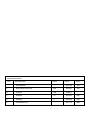


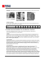

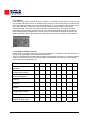


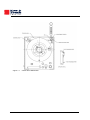


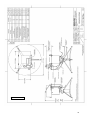
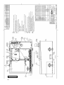

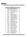
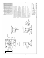
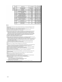
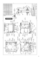

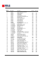
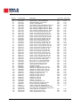
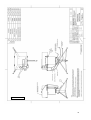
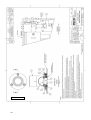

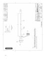

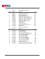
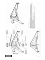

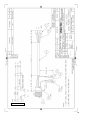

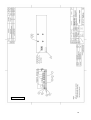

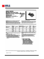
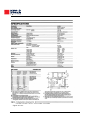


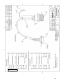
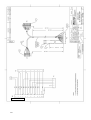

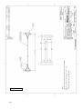
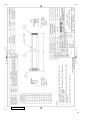

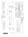


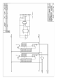
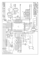


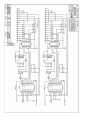
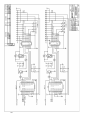
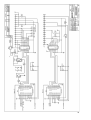
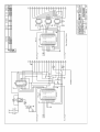
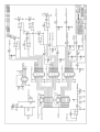
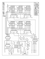

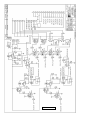


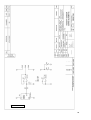
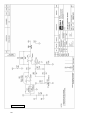
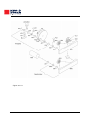

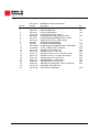
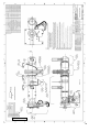
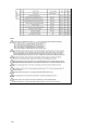
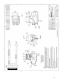

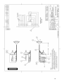

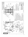
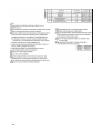


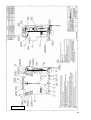
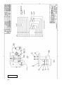
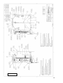
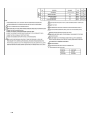

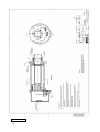


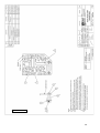


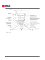
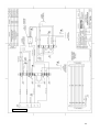
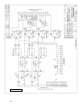

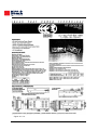
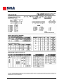


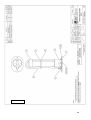


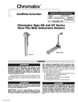

![sf-list [s]](http://vs1.manualzilla.com/store/data/005727021_1-5e70d84b679a2d9887789b982f459474-150x150.png)