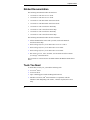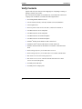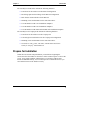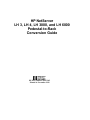
1
HP NetServer LH 3, LH 4, LH 3000, and LH 6000 Pedestal-to-Rack Conversion Guide HP Part Number 5969-2162 Printed in November 1999 Notice The information contained in this document is subject to change without notice. Hewlett-Packard makes no warranty of any kind with regard to this material, including, but not limited to, the implied warranties of merchantability and fitness for a particular purpose. Hewlett-Packard shall not be liable for errors contained herein or for incidental or consequential damages in connection with the furnishing, performance, or use of this material. Hewlett-Packard assumes no responsibility for the use or reliability of its software on equipment that is not furnished by Hewlett-Packard. This document contains proprietary information that is protected by copyright. All rights are reserved. No part of this document may be photocopied, reproduced, or translated to another language without the prior written consent of HewlettPackard Company. 3M® is a registered trademark of Minnesota Mining and Manufacturing Company. Compaq® is a registered trademark of Compaq Computer Corporation. Intel inside® is a registered trademark of Intel Corporation. Pentium® is a registered trademark of Intel Corporation. Torx® is a registered trademark of Camcar Division of Textron, Incorporated. Xeon is a trademark of Intel Corporation. Hewlett-Packard Company Network Server Division Technical Communications / MS 45SLE 10955 Tantau Avenue Cupertino, CA 95014 USA © Copyright 1999, Hewlett-Packard Company Audience Assumptions This guide is for the person who installs, administers, and troubleshoots LAN servers. Hewlett-Packard Company assumes you are qualified in the servicing of computer equipment and trained in recognizing hazards in products with hazardous energy levels. ii Contents Preface ...................................................................................................................1 About this Guide .................................................................................................1 Related Documentation......................................................................................2 Tools You Need..................................................................................................2 1 Introduction ......................................................................................................3 Overview.............................................................................................................3 Warnings ............................................................................................................4 Verify Contents ...................................................................................................6 Prepare for Installation .......................................................................................7 2 Remove Bezel, Cover, and Components .......................................................9 Overview of Removal of Front Bezel, Rack Rail Cover, and Components ........9 Disconnect the NetServer ..................................................................................9 Remove the Front Bezel and Rack Rail Cover.................................................11 Remove the Front Bezel ..............................................................................11 Remove the Rack Rail Cover.......................................................................12 Lighten the NetServer.......................................................................................14 Remove Hot-Swap Hard Disk Drives ...........................................................14 Remove Power Supply Modules ..................................................................15 Move the NetServer..........................................................................................17 Remove the Casters.........................................................................................17 3 Conversion: Install Components, Cover, and Front Bezel ........................19 Overview of Conversion to Rack-Optimized Configuration ..............................19 Install Memory or Accessory Boards ................................................................19 Install the Lifting Handles .................................................................................20 Reorient the Control Panel ...............................................................................21 Install the NetServer in the Rack ......................................................................24 Attaching the Cable Management Arm ........................................................29 Replace Power Supply Modules and Hard Disk Drives....................................31 Install Chassis Retention Bracket when Shipping an HP Rack........................32 Install the New Front Bezel...............................................................................33 Prepare the Front Bezel ...............................................................................33 Attach the Front Bezel..................................................................................35 Reconnect the Power Cords and Cables .........................................................37 iii Contents 4 Warranty and Support....................................................................................39 Hardware Accessories Limited Warranty.........................................................39 Hewlett-Packard Hardware Accessories......................................................39 Third-Party Hardware Products....................................................................40 HP Repair and Telephone Support ..................................................................40 A Regulatory Information..................................................................................41 Index ....................................................................................................................43 iv Preface About this Guide This guide describes how to convert the pedestal configuration HP NetServer LH 3, LH 4, LH 3000, or LH 6000 to the rack-optimized configuration HP NetServer LH 3r, LH 4r, LH 3000r, or LH 6000r. This guide refers to two general types of rack enclosures: • HP Rack: This guide's designation for all of the following rack enclosures: ◊ HP Systems rack enclosure product numbers J1487B and J1488A ◊ HP Rack System/E rack enclosure product numbers J1500A, J1501A, J1502A ◊ HP Rack System/U rack enclosure product numbers J1464A and J1466A • Compaq Rack: This guide's designation for the Compaq® 4000/7000 rack enclosures NOTE The instructions in this guide are specifically for Hewlett-Packard rack enclosure product numbers J1464A, J1466A, J1487B, J1488A, J1500A, J1501A, and J1502A and the Compaq 4000/7000 rack enclosures. For information about other rack installations, see the rack-mount kit instructions that come with your rack or NetServer, or refer to the following web site: http://www.hp.com/go/enclosures 1 Chapter Preface Related Documentation The following documents describe the NetServer: • HP NetServer LH 3/LH 3r User Guide • HP NetServer LH 4/LH 4r User Guide • HP NetServer LH 3000/3000r Installation Guide • HP NetServer LH 6000/6000r Installation Guide • HP NetServer LH 3 Installation Road Map • HP NetServer LH 3r Installation Road Map • HP NetServer LH 4 Installation Road Map • HP NetServer LH 4r Installation Road Map The following documents describe the rack enclosures: • All documentation that comes with your rack, such as the HP Rack Installation Road Map • Rack Cabling Reference for the HP NetServer LH 3r or LH 4r • Rack Cabling Reference for the HP NetServer LH 3000r • Rack Cabling Reference for the HP NetServer LH 6000r • HP NetServer LH 3r, LH 4, LH 3000r, and LH 6000r Installation Guide for Compaq® 4000/7000 Racks The HP NetServer Documentation CD-ROM contains the HP documents listed above. Tools You Need To install this accessory kit, you need the following tools: • • • • 2 T-15 Torx® driver T-25 Torx driver Tape or marking pen to mark mounting hole locations Antistatic service kit (3M® 8501/8502/8503 or equivalent). This kit includes a static-dissipating work surface, a chassis clip lead, and a wrist strap. 1 Introduction Overview This guide describes the procedure for converting the HP NetServer LH 3, LH 4, LH 3000, and LH 6000 (pedestal configuration) to the HP NetServer LH 3r, LH 4r, LH 3000r, or LH 6000r (rack-optimized configuration). For details of installing the NetServer into the rack enclosure, refer to the following: • For a NetServer in an HP rack: your NetServer's user guide or installation guide • For a NetServer in a Compaq rack: HP NetServer LH 3r, LH 4r, LH 3000r, or LH 6000r Installation Guide for Compaq® 4000/7000 Racks For cabling details, refer to the appropriate one of the following: • Rack Cabling Reference for the HP NetServer LH 3r • Rack Cabling Reference for the HP NetServer LH 4r • Rack Cabling Reference for the HP NetServer LH 3000r • Rack Cabling Reference for the HP NetServer LH 6000r Briefly, the conversion and installation include these general steps: 1. Gather the tools and documentation needed to perform the conversion and installation. 2. Power down the NetServer and disconnect power cord(s) and cables. 3. Remove the front bezel, rack rail cover, hard disk drives, and power supply modules. 4. Move the NetServer to a bench area, and position it on its side (Cover 1 up, and Cover 3 down). Remove the casters from the NetServer, and install any additional memory or accessory boards. Attach the lifting handles to the NetServer. 3 Chapter 1 Introduction 5. Remove the plastic lock pawl (which engages and secures the bezel lock mechanism) from the NetServer chassis front. Unfasten the control panel from the chassis, reorient it, and then secure it to the chassis again. Install the control panel bezel. 6. Install the slides in the rack, and install the NetServer in the rack. 7. Replace the power supply modules and hard disk drives. 8. For shipping HP racks, install the rack chassis retention bracket to secure the NetServer to the rear of the rack. 9. Install the bezel mounting hardware, and install the new front bezel. 10. Install the Cable Management Arm. 11. Reconnect the AC power cord(s) and other external cables. Warnings Observe the warnings below to prevent harm to you or the NetServer. Also observe all cautions and warnings in this document and other documents to protect people, the NetServer, components, and other equipment. WARNING 4 Before removing the cover, always disconnect the power cord(s) and unplug telephone cables. Disconnect the power cord(s) to avoid exposure to high energy levels that may cause burns when parts are short-circuited by metal objects, such as tools or jewelry. Disconnect telephone cables to avoid exposure to shock hazard from telephone ringing devices. Note that the power switch does not turn off the standby power. Disconnect the power cord(s) to turn off standby power. If the backlight on the LCD display is on, standby power is still on. Chapter 1 WARNING Introduction To prevent the rack enclosure from tipping over: • Extend the anti-tip foot or verify that the anti-tip feature is installed. • Verify that the leveler feet are lowered. • Do NOT extend more than one piece of equipment at a time out from the front of the rack. Failure to take these precautions could result in serious injury and equipment damage. WARNING Do not attempt to lift the NetServer by yourself. Follow all local regulations when moving the NetServer. Failure to observe this warning could result in serious injury to personnel or damage to the NetServer. The HP NetServer LH 3r weighs up to 115 pounds (73 kg) when fully loaded. The HP NetServer LH 4r weighs up to 176 pounds (80 kg) when fully loaded. The HP NetServer LH 3000r weighs up to 118 pounds (54 kg) when fully loaded. The HP NetServer LH 6000r weighs up to 180 pounds (80 kg) when fully loaded. 5 Chapter 1 Introduction Verify Contents Unpack and verify the contents of the shipping box. If anything is missing or damaged, contact your reseller. The conversion kit includes two assembly kits, one for HP racks, and one for Compaq racks. In addition, it includes the following hardware: • Four lifting handles and their screws • Two rack slides, bar nuts, rack nuts, and their screws and hardware • Control panel bezel • Four AC power cords: two for 100-120 V, and two for 200-240 V • Two HP NetServer LH 3r nameplates • Two HP NetServer LH 4r nameplates • Two HP NetServer LH 3000r nameplates • Two HP NetServer LH 6000r nameplates • Pentium® II label for HP NetServer LH 3r front bezel • Pentium II Xeon® label for HP NetServer LH 4r front bezel • Pentium® III Xeon label for HP NetServer LH 3000r or LH 6000r front bezel • Rack Cabling Reference for the HP NetServer LH 3r • Rack Cabling Reference for the HP NetServer LH 3000r and LH 6000r • HP NetServer LH 4r Rack Cabling Reference • HP NetServer LH 3, LH 4, LH 3000 and LH 6000 Pedestal-to-Rack Conversion Guide (this guide) • Assembly kit for HP racks • Assembly kit for Compaq racks 6 Chapter 1 Introduction The assembly kit for HP racks includes the following hardware: • Front bezel for the NetServer in the HP rack configuration • Bezel hinge plate and bezel hinge for the HP rack configuration • Rack chassis retention bracket for the HP rack • Mounting screws and hardware for the items listed above • Two HP NetServer LH 3r rack installation templates • Two HP NetServer LH 4r rack installation templates • Two HP NetServer LH 3000r and LH 6000r rack installation templates The assembly kit for Compaq racks includes the following hardware: • Front bezel for the NetServer in the Compaq rack • Left and right recessed brackets for the Compaq rack configuration • Mounting screws and hardware for the items listed above • HP NetServer LH 3, LH 4r, LH 3000r, and LH 6000r Installation Guide for Compaq® 4000/7000 Racks Prepare for Installation Gather the tools and the setup information you need before beginning the conversion. Place the NetServer where there will be sufficient space to remove the covers, power supply modules, and disk drives. If you plan to add accessory boards or additional memory, reserve bench space at a comfortable level so you can reach the interior of the NetServer easily. 7 2 Remove Bezel, Cover, and Components Overview of Removal of Front Bezel, Rack Rail Cover, and Components Before you convert the NetServer to the rack-optimized configuration, you will do the following: • Power down the NetServer and disconnect it. • Remove the front bezel and rack rail cover. • Lighten the NetServer by removing the hot-swap disk drives and the power supply modules. • Move the NetServer to a suitable work area. • Remove the casters. Disconnect the NetServer Do the following to power down the NetServer and disconnect it: 1. Back up your system. 2. Bring down the network properly. 3. Turn off power to the HP NetServer. 4. Disconnect the AC power cord(s) and all external cables from the HP NetServer. 9 Chapter 2 Remove Bezel, Cover, and Components WARNING Before removing the cover, always disconnect the power cord(s) and unplug telephone cables. Disconnect the power cord(s) to avoid exposure to high energy levels that may cause burns when parts are short-circuited by metal objects, such as tools or jewelry. Disconnect telephone cables to avoid exposure to shock hazard from telephone ringing devices. Note that the power switch does not turn off the standby power. Disconnect the power cord(s) to turn off standby power. If the backlight on the LCD display is on, standby power is still on. CAUTION Never operate this HP NetServer without first installing the covers and the front bezel. Operating the system without the covers in place reduces critical cooling airflow over some components, such as power supply modules, hard disk drives, and processor modules. Operating the system without the covers in place may result in failure of these components. If you open the HP NetServer LH 3/3r or LH 4/4r while it is operating, do not run it for more than 2 minutes. If you open the HP NetServer LH 3000/3000r or LH 4000/4000r while it is operating, do not run it for more than 60 minutes. Failure to observe these precautions may result in thermal damage to the NetServer. CAUTION 10 Wear a wrist strap and use a static-dissipating work surface connected to the chassis when you remove or install components. Chapter 2 Remove Bezel, Cover, and Components Remove the Front Bezel and Rack Rail Cover The rack rail cover is the only NetServer cover that must be removed during the conversion of the NetServer from pedestal configuration to rack configuration. First, unlock and remove the front bezel to gain access to the screw securing the rack rail cover. Remove the Front Bezel The front bezel for the pedestal configuration connects to the front of the NetServer chassis with snap-in connectors at the top front of the chassis and tabs that fit into two slots on the bottom front of the chassis. To remove the bezel, unlock the bezel lock with the key, and pull the bezel forward until it unsnaps. Then lift the bezel forward and upward from the chassis face, as shown in Figure 2-1. 11 Chapter 2 Remove Bezel, Cover, and Components Bezel Lock Pull Here Rack Rail Cover Figure 2-1. Remove Front Bezel Remove the Rack Rail Cover Remove the rack rail cover, as shown in Figure 2-2: 1. Unscrew the screw on the front of the cover. 2. Pull the cover forward and then sideways to disengage it. 3. Lift the cover away from the chassis. 12 Chapter 2 Remove Bezel, Cover, and Components 1 Unscrew Rack Rail Cover 3 2 Figure 2-2. Remove the Rack Rail Cover 13 Chapter 2 Remove Bezel, Cover, and Components Lighten the NetServer Before you lift the NetServer, remove the hot-swap hard disk drives and power supply modules. This will lighten the NetServer, so that fewer people will be needed to lift it. WARNING Do not attempt to lift the NetServer by yourself. Follow all local regulations when moving the NetServer. Failure to observe this warning could result in serious injury to personnel or damage to the NetServer. Take out power supplies and hot-swap hard disk drives before lifting the NetServer. The HP NetServer LH 3r weighs up to 115 pounds (73 kg) when fully loaded. The HP NetServer LH 4r weighs up to 176 pounds (80 kg) when fully loaded. The HP NetServer LH 3000r weighs up to 118 pounds (54 kg) when fully loaded. The HP NetServer LH 6000r weighs up to 180 pounds (80 kg) when fully loaded. Remove Hot-Swap Hard Disk Drives CAUTION Wear a wrist strap and use a static-dissipating work surface connected to the chassis when you remove or install hot-swap disk drive modules. 1. Refer to Figure 2-3. To unlock the drive, push the locking latch in and then pull the ejector handle toward you. 2. Gently pull the drive out about an inch to disengage the power connection. 3. Use your hand to support the bottom of the drive. Slowly pull the drive straight out. Do not allow the drive to fall. 4. Place the drive in an electrostatic-protected container or on an electrostaticprotected surface. Do not stack drives. 14 Chapter 2 Remove Bezel, Cover, and Components Locking Latch Ejector Handle Figure 2-3. Remove Hard Disk Drives From the NetServer Remove Power Supply Modules To remove the power supply modules, unscrew the modules and pull them away from the NetServer, as shown in Figure 2-4. Put them aside for later reinstallation. CAUTION When lifting a power supply module, be prepared to support its weight. Hold the power supply module with two hands. 15 Chapter 2 Remove Bezel, Cover, and Components Figure 2-4. Remove Power Supply Modules (Rear View of HP NetServer LH 3 Shown; Number of Power Supply Modules May Vary) 16 Chapter 2 Remove Bezel, Cover, and Components Move the NetServer Using enough people for safe handling, lift the NetServer onto an empty work surface for easy access to the interior and to the face of the chassis. Rotate the NetServer so that Cover 1 is now on top, as shown in Figure 2-5. (Cover 2, which was the top of the pedestal configuration, becomes the right side of the rack-optimized configuration.) Cover 1 Cover 2 Becomes Right Side of Rack-Optimized Configuration Figure 2-5. Remove the Casters (Front View) Remove the Casters Remove the casters from the NetServer by unfastening the screws that secure them to the NetServer chassis. 17 3 Conversion: Install Components, Cover, and Front Bezel Overview of Conversion to Rack-Optimized Configuration To complete the conversion of the NetServer to the rack-optimized configuration, you will do the following: • Install any additional memory or accessory boards. • Install four lifting handles. • Reorient the control panel. • Install the NetServer in the rack. • Replace the power supply modules and hard disk drives. • Install the chassis retention bracket on an HP rack. • Install the new front bezel. • Reconnect the power cord(s) and external cables. Install Memory or Accessory Boards If you plan to install additional memory or an accessory board, refer to the documentation accompanying the memory or accessory board and install it now. 19 Chapter 3 Conversion: Install Components, Cover, and Front Bezel Install the Lifting Handles Install lifting handles for use when you mount the NetServer on the rack slides. The four handles mount two to a side. Use the provided screws to mount the handles, as shown in Figure 3-1. Figure 3-1. Install the Lifting Handles 20 Chapter 3 Conversion: Install Components, Cover, and Front Bezel Reorient the Control Panel The control panel must be repositioned to be easily readable in the rack-mount position. Reposition the control panel and its bezel, as follows: 1. Unscrew the two screws securing the control panel to the chassis. 2. Unhook the control panel from the face of the chassis, as shown in Figure 3-2. A ribbon cable still connects it to the NetServer. Lock Pawl Control Panel Figure 3-2. Detach Control Panel from NetServer Chassis 3. Remove the lock pawl by squeezing the base until the tabs disengage from the mounting slots, as shown in Figure 3-2. The lock pawl is not used on the rack-optimized configuration of the NetServer. 21 Chapter 3 Conversion: Install Components, Cover, and Front Bezel 4. Rotate the control panel until it is aligned with the rack position of the NetServer, as shown in Figure 3-3. Be careful of the ribbon cable that connects the control panel to the NetServer. Be careful not to damage it. Compaq rack slots (on left) HP rack slots (on right) Control Panel Figure 3-3. Reorient Control Panel to NetServer Chassis NOTE There are two possible positions for the reinstallation of the control panel, depending upon the rack in which the NetServer will reside. Refer to Figure 3-3. 5. Refer to Figure 3-3. Mount the control panel in the set of slots appropriate for your rack: 22 ◊ Slots for the HP rack are on the right. ◊ Slots for the Compaq rack are on the left. Chapter 3 Conversion: Install Components, Cover, and Front Bezel As you mount the control panel, ensure that the ribbon cable goes completely back inside the NetServer. Do not damage the ribbon cable with the control panel. 6. Replace the two screws to secure the control panel to the chassis. 7. Refer to Figure 3-4. Mount the control panel bezel over the control panel in the set of slots appropriate for your rack: ◊ ◊ Slots for the HP rack are on the right. Slots for the Compaq rack are on the left. Compaq rack slots (on left) HP rack slots (on right) Figure 3-4. Reattach the Control Panel Bezel 23 Chapter 3 Conversion: Install Components, Cover, and Front Bezel Install the NetServer in the Rack Refer to the documentation listed below to install the slides in the rack and to install the NetServer into the rack: • To install into an HP rack: Refer to the NetServer's user guide or installation guide. For cabling instructions, refer to the documentation that came with the rack and either the Rack Cabling Reference for your HP NetServer. • To install into a Compaq Rack: Refer to the HP NetServer LH 3r, LH 4r, LH 3000r, and LH 6000r Installation Guide for Compaq® 4000/7000 Racks. For cabling instructions, refer to the documentation that came with the rack and either the Rack Cabling Reference for your HP NetServer. Refer to this rack documentation for detailed instructions as you do the following: 1. Extend the anti-tip foot or ensure that the anti-tip feature is installed. Lower the leveler feet. WARNING To prevent the rack enclosure from tipping over, • Extend the anti-tip foot or verify that the anti-tip feature is installed. • Verify that the leveler feet are lowered. • DO NOT extend more than one piece of equipment at a time out from the front of the rack. Failure to take these precautions could result in serious injury and equipment damage. 2. If there is a door on the rack, remove it. 24 Chapter 3 Conversion: Install Components, Cover, and Front Bezel 3. Mark locations on the rack columns for all bar nuts and rack nuts to hold the rack slides and bezel mounting hardware. ◊ For HP racks, use the appropriate rack installation template for your rack: ∗ For HP Systems racks, use the installation template labeled LH 3r (HP Systems), the installation template labeled LH 4r (HP Systems), or the installation template labeled LH 3000r and LH 6000r (HP Systems). ∗ For HP Rack System/E racks and HP Rack System/U racks, use the installation template labeled LH 3r (HP Rack System/E), the installation template labeled LH 4r (HP Rack System/E), or the installation template labeled LH 3000r and LH 6000r (HP Rack System/E). Be sure to mark holes 9 and 13 above the base line for the rack nuts that will hold the chassis retention bracket. ◊ For Compaq racks, count up from the top of the unit below, marking the 20th and 22nd holes on all four columns, as described in the HP NetServer LH 3r, LH 4r, LH 3000r, and LH 6000r Installation Guide for Compaq® 4000/7000 Racks. 4. Install all bar nuts and rack nuts to hold the rack slides and bezel mounting hardware. For HP racks, be sure to install the rack nuts for the chassis retention bracket, as shown in Figure 3-5. 25 Chapter 3 Conversion: Install Components, Cover, and Front Bezel Right Rear Column of HP Rack Hole 13 above Base Line Hole 9 above Base Line Rack Nuts Figure 3-5. Position Rack Nuts for Chassis Retention Bracket 5. Install the rack slides (slide members). 6. Install the NetServer onto the rack slides. 7. 26 Remove the four lifting handles from the NetServer after the NetServer is installed onto the rack slides and the screws holding the NetServer to the slides are tightened. Chapter 3 Conversion: Install Components, Cover, and Front Bezel WARNING Do not attempt to lift the NetServer by yourself. Follow local regulations when lifting the NetServer. Failure to observe this warning could result in serious injury to personnel or damage to equipment. The HP NetServer LH 3r weighs approximately 115 pounds (52 kg) after the hard disk drives and power supply modules are removed. The HP NetServer LH 4r weighs approximately 145 pounds (66 kg) after the hard disk drives and power supply modules are removed. The HP NetServer LH 3000r weighs approximately 118 pounds (54 kg) after the hard disk drives and power supply modules are removed. The HP NetServer LH 6000r weighs approximately 148 pounds (67 kg) after the hard disk drives and power supply modules are removed. 8. Slide the NetServer into the rack. 9. Install the bezel mounting hardware, which also secures the front of the NetServer to the rack: ◊ For the HP rack, the bezel mounting hardware is the bezel hinge and latch assembly. The bezel hinge is a long plastic part with five screw holes, two on the left and three on the right, as shown in Figure 3-6. The latch assembly is a small metal part with four screw holes and a black plastic latch mounted on it, as shown in Figure 3-6. Attach this hardware as described in the NetServer's user guide or installation guide. 27 Chapter 3 Conversion: Install Components, Cover, and Front Bezel Latch Assembly Bezel Hinge Figure 3-6. Mounting Hardware for Front Bezel for HP Rack ◊ 28 For the Compaq rack, the bezel mounting hardware is the left and right recessed brackets, as shown in Figure 3-7. The left recessed bracket is a long part with four screw holes. The right recessed bracket is a small metal part with four screw holes, but no latch. Attach this hardware as described in the HP NetServer LH 3r, LH 4r, LH 3000r, and LH 6000r Installation Guide for Compaq® 4000/7000 Racks. Chapter 3 Conversion: Install Components, Cover, and Front Bezel Compaq Rack Figure 3-7. Mounting Hardware for Front Bezel for Compaq Rack Attaching the Cable Management Arm The Cable Management Arm for the HP NetServer can only be mounted on HP Systems racks. The HP NetServer Cable Management Arm allows the cables, including the power cords, to move in and out with the HP NetServer chassis on its slides without being accidentally disconnected (see Figure 3-8). WARNING Before sliding out the HP NetServer, ensure the anti-tip foot from under the front of the rack is extended or the anti-tip feature is installed. A tip-over hazard exists, so never slide more than one component out of the rack at a time. 1. Ensure the HP NetServer is pushed all the way into the rack. 2. At the rear of the NetServer, place rack nuts on the left column in the 17th and 18th holes above the baseline of the HP NetServer (see Figure 3-8). 29 Chapter 3 Conversion: Install Components, Cover, and Front Bezel Rear of NetServer Left Rear Rack Column Cable Management Arm Figure 3-8. Attaching the Cable Management Arm 3. Install the two 6-32 Torx T-15 screws in the two threaded holes on the rear of the NetServer. 4. Orient the cable management arm as shown in Figure 8-17. 5. Install the flange over the 6-32 screws and tighten them. 6. Attach the other flange of the cable arm to the rear column of the rack with the two M-5 Torx T-25 screws, included with the arm. 7. Extend the HP NetServer out of the rack to ensure the Cable Management Arm moves with the chassis without binding. 8. Slide the HP NetServer back into the rack. 9. At the front of the rack, insert the screws through the flanges into the rack nuts and secure the HP NetServer to the front rack columns with a Torx T-25 driver. Each of the HP NetServer's two front flanges has two slots, which should line up with the rack nuts previously mounted on the rack columns. 30 Chapter 3 Conversion: Install Components, Cover, and Front Bezel 10. Plug the HP NetServer's power cable and all available data cables into the back of the HP NetServer. Replace Power Supply Modules and Hard Disk Drives Do the following to replace the power supply modules and hot-swap hard disk drive modules: 1. Refer to the NetServer's user guide or installation guide to replace the power supply modules in the power supply cage. Ensure that the modules are seated correctly, and then fasten the thumbscrews. 2. Refer to the NetServer's user guide or installation guide to replace the hard disk drive modules in the hot-swap mass storage cage. Make sure the locking pin engages the cage lip and secures the module in position. 31 Chapter 3 Conversion: Install Components, Cover, and Front Bezel Install Chassis Retention Bracket when Shipping an HP Rack For the HP rack, the rack nuts for the chassis retention bracket were installed on the right rear rack column. For the HP rack, install the chassis retention bracket and secure the NetServer to it, as follows: 1. Position the bracket as shown in Figure 3-9. Right Rear Column of HP Rack Hole 13 above Base Line Rack Nuts Hole 9 above Base Line Chassis Retention Bracket Figure 3-9. Screw Bracket to Rack and NetServer (Shown for HP NetServer LH 3r; Number of Power Supply Modules May Vary) NOTE The Chassis Retention Bracket is only required for shipping the system in an HP rack. 2. Fasten the bracket to the rack with the two 10x32 screws. 3. Fasten the bracket to the NetServer with the two 6x32 screws. For the HP rack with an anti-tip foot, retract the anti-tip foot if other components will not be extended from the front of the rack. 32 Chapter 3 Conversion: Install Components, Cover, and Front Bezel Install the New Front Bezel The conversion kit contains two assembly kits, one for the HP rack, and one for the Compaq rack. Each assembly kit contains the new front bezel for the NetServer in the specific type of rack, as shown in Figure 3-10. Front Bezel for HP Rack Front Bezel for Compaq Rack Figure 3-10. Front Bezels for HP Rack and Compaq Rack Prepare the appropriate front bezel before you attach it, as described below. Prepare the Front Bezel Prepare the front bezel by attaching the appropriate nameplate and the appropriate processor label. Two nameplates are supplied for each NetServer, one to use in an HP rack and one to use in a Compaq rack. • Use the wider nameplate, which has three snap posts on the back, for an HP rack. • Use the narrower nameplate for a Compaq rack. Attach the appropriate nameplate to the top of the front surface of the front bezel: 1. Orient the nameplate so that it can be read correctly when attached. 33 Chapter 3 Conversion: Install Components, Cover, and Front Bezel 2. Secure the nameplate to the front bezel, as follows: ◊ For the HP rack front bezel, insert the tab at one end of the nameplate into the slot in the bezel, bend the nameplate slightly, and simultaneously insert the snaps on the back of the nameplate and the tab at the other end of the nameplate. ◊ For the Compaq rack front bezel, insert the snap at one end of the nameplate, and then insert the other snaps successively. The conversion kit contains two processor labels: • Label reading "intel inside® pentium II" is for the HP NetServer LH 3r. • Label reading "intel inside pentium II xeon" is for the HP NetServer LH 4r. • Label reading "intel inside® pentium III xeon" is for the HP NetServer LH 3000r and LH 6000r. 3. Attach the appropriate label to a convenient location near a corner of the front bezel. 34 Chapter 3 Conversion: Install Components, Cover, and Front Bezel Attach the Front Bezel After the new front bezel is prepared, push it into place, as shown in Figure 3-11 or 3-12. Figure 3-11. Push Front Bezel into Place on HP Rack 35 Chapter 3 Conversion: Install Components, Cover, and Front Bezel Figure 3-12. Push Front Bezel into Place on Compaq Rack 36 Chapter 3 Conversion: Install Components, Cover, and Front Bezel Reconnect the Power Cords and Cables Complete the installation of the NetServer, as follows: 1. If you removed the door of the rack, replace it. 2. Reconnect the AC power cord(s) and other external cables as described in the Rack Cabling Reference for your HP NetServer. 3. Attach the power cord retainer for each AC power cord, as shown in Figure 3-13. Squeeze the two long metal tabs toward each other, and slide the wire bail over the tabs. Two Long Tabs on Retainer Wire Bail of Retainer Power Cord Figure 3-13. Attach Power Cord Retainer 37 4 Warranty and Support The hardware warranty below applies to components purchased as accessories. If your component was factory installed as part of an HP NetServer model, refer to the warranty statement provided with your system documentation. Hardware Accessories Limited Warranty Hewlett-Packard Hardware Accessories An HP NetServer Hardware Accessory is an HP hardware product that is specifically designated for use with HP NetServers; is added on or integrated into an HP NetServer in order to provide higher performance, capacity, or increased capability; and is listed as a product in HP's Corporate Price List. Upon installation inside an HP NetServer, the HP NetServer Hardware Accessory carries a System-Matching Warranty. This warranty includes a one-year Return-to-HP warranty or the remainder of the warranty period for the original HP NetServer in which it is installed, whichever is longer. This accessory may be serviced through expedited part shipment. In this event, HP will prepay shipping charges, duty, and taxes; provide telephone assistance on replacement of the component; and pay shipping charges, duty, and taxes for any part that HP asks to be returned. HP warrants this HP NetServer Hardware Accessory against defects in material and workmanship, under normal use, for the period specified in the section titled HP NetServer Limited Warranty Coverage. The warranty commences on receipt of this product by Customer from HP or Reseller. If HP or Reseller receives notice of such defects during the warranty period, HP or Reseller will either, at its option, repair or replace products that prove to be defective. Should HP or Reseller be unable to repair or replace the hardware accessory within a reasonable amount of time, Customer's alternate remedy shall be a refund of the purchase price upon return of the hardware accessory product. HP products external to the system processor unit, such as external storage subsystems, printers, or other peripherals, are covered by the applicable warranty for those products. The customer may be required to run HP-supplied configuration and diagnostic programs before a replacement will be dispatched or an on-site visit is authorized. 39 Chapter 4 Warranty and Support Refer to the warranty statement provided with your original HP NetServer system documentation for the warranty limitations, customer responsibilities, and other terms and conditions. Third-Party Hardware Products HP does not warrant third-party hardware products. Third-party hardware products may be warranted in accordance with the third-party warranty statement accompanying the product. On-site visits caused by third-party hardware products—whether internal to the HP NetServer system processor unit (such as non-HP DIMMs) or external to the system processor unit (such as LAN cabling)—are subject to standard per-incident travel and labor charges. HP Repair and Telephone Support Refer to the HP NetServer Warranty and Service/Support Booklet supplied with your HP NetServer system documentation for instructions on how to obtain HP repair and telephone support. 40 A Regulatory Information For regulatory information pertaining to this HP accessory, please refer to the regulatory section of the user guide for the NetServer in which this accessory is installed. 41 Index A Accessory boards, installing, 21 Accessory kit contents, 8 Anti-tip feature, 26 Anti-tip foot, 26 Arm, cable management, 31 Assembly kit for Compaq racks, 9 Assembly kit for HP racks, 9 Assembly kits, 8 B Bar nuts, 27 Bezel hinge, 29 Bezel, control panel, 25 Bezel, front installing, 35, 37 mounting hardware, 27, 29 mounting hardware for Compaq rack, 30 mounting hardware for HP rack, 29 removing, 13 types, 35 C Cabling references, 5 Casters, removing, 19 Caution antistatic, 12, 16 power supply modules, 17 thermal, 12 Chassis retention bracket, 27, 34 Compaq rack bezel mounting hardware, 30 enclosures, 1 installation, 26, 27 Connecting the NetServer, 39 Contents of upgrade kit, 8 Control panel, 23, 24 Control panel bezel, 25 Conversion overview, 21 D Disconnecting the NetServer, 11 Documentation, 2 Door of rack, 26, 39 G Getting help, 41 H Handles, lifting, 22, 28 Hardware accessories limited warranty, 41 Hardware repair warranty information for, 41 Help, 41 Hot-swap hard disk drives removing, 16 replacing, 33 HP rack bezel mounting hardware, 29 enclosures, 1 installation, 26, 27 I Installing into a Compaq rack, 26, 27 Installing into an HP rack, 26, 27 Introduction, 5 K Kit contents, 8 L Latch assembly, 29 Leveler feet, 26 Lifting handles, 22, 28 M Memory, installing, 21 Moving the NetServer, 7, 16, 19, 28 43 Index N Nameplate, 35 O Overview, general, 5 P Power cord retainer, 39 Power supply modules removing, 17 replacing, 33 Powering down, 11 Processor label, 35 R Rack door, 26, 39 Rack enclosure types, 1 Rack installation into a Compaq rack, 26, 27 into an HP rack, 26, 27 Rack installation template, 27 Rack nuts, 27 Rack rail cover, 14 44 Rack slides, 27, 28 Recessed brackets, 30 Regulatory information, 43 S Slide location, 27 Slides (slide members), 27, 28 Static-dissipating work surface, 12, 16 T Tools needed, 2 W Warning anti-tip, 7, 26 high energy levels, 6, 12 reduce lifting weight, 16, 29 shock hazard, 6, 12 Warnings, 6 Warranty for hardware, 41 hardware accessories limited, 41