1
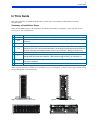
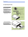
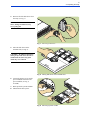
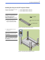
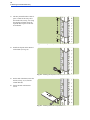
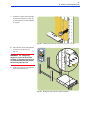
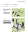
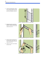
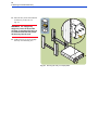
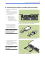
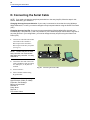
HP SureStore Virtual Array 7100
Quick Start Guide
Edition E0201
Order Part Number: A6183-90901
www.hp.com/support/va7100
Notice
Typographical Conventions
© Hewlett-Packard Company, 2001. All rights reserved.
Hewlett-Packard Company makes no warranty of any kind
with regard to this document, including, but not limited to,
the implied warranties of merchantability and fitness for a
particular purpose. Hewlett-Packard shall not be liable for
errors contained herein or for incidental or consequential
damages in connection with the furnishing, performance, or
use of this material.
This document contains proprietary information, which is
protected by copyright. No part of this document may be
photocopied, reproduced, or translated into another language
without the prior written consent of Hewlett-Packard. The
information contained in this document is subject to change
without notice.
WARNING! Indicates procedures or practices
which, if not observed, could result in personal
injury.
CAUTION! Indicates procedures which, if not
observed, could result in damage to equipment or loss of
data.
NOTE: Indicates significant concepts or important
information or operating instructions.
Warranty
If you have any questions about the warranty for this product, contact your dealer or local Hewlett-Packard sales representative.
this font Used for text to be typed verbatim: all commands, path names, and file names; also used for menu and
button selections in graphical user interfaces.
this font Used for text displayed on the screen.
1
In This Guide
In This Guide
This guide shows how to install the HP SureStore Virtual Array 7100 deskside, field-rackable, and factoryracked products.
Summary of Installation Steps:
Follow the installation steps in the table below. Check them off as they are completed. (Some steps may not be
necessary for your configuration.)
✔ Section
A
B
C
D
E
F
G
H
Installation Step*
Unpack the array.
Is your array a field-rackable product? If YES, install the array into a rack. If NO, go to
Section C.
Connect the power cables and host fibre channel cables to the array.
Do you need to change the array host port behavior (Section F) or the array loop IDs
(Section G)? If YES, connect the serial cable to the array RS-232 port and to an RS-232
terminal, and start a terminal emulator. If NO, go to Section E then go to Section H.
Power-on the array and verify that it passes self-test.
Is the array connected to a host running Windows 2000, Windows NT, or Linux? If YES,
change the array host port behavior. If NO (host running HP-UX), go to Section G.
Are any other devices using loop ID 108 or 110? If YES, change the array loop IDs. If
NO, go to Section H.
Install the array software. Refer to the HP Command View SDM User’s Guide.
*The installation steps in this guide show only field- and factory-racked arrays for simplicity. The deskside array
differs from the racked array mainly in its orientation (see Fig. 1 through Fig. 4). Refer to these figures when locating
corresponding parts on a deskside array.
Fig. 1. Deskside Array - Front View
Fig. 3. Racked Array - Front View
Fig. 2. Deskside Array - Rear View
Fig. 4. Racked Array - Rear View
2
A. Unpacking the Array
A. Unpacking the Array
NOTE: If you are installing a factoryracked array, skip steps 1 through 6
and go to directly to step 7.
1.
Quick Start Guide
User’s Guide
Unpack the array.
Power Cords
NOTE: Follow the instructions on
top of the shipping container.
2.
Serial Cable
Check the contents of the shipping
container (see Fig. 5).
Optical Fibre Cable
VA7100 Array
Fig. 5. Checking the shipping container contents
3.
Remove the foam packaging from
the front of the array (see Fig. 6).
NOTE: If you are installing a
deskside array, go to step 7 now.
Fig. 6. Removing the foam disk drive cover
3
A. Unpacking the Array
4.
Remove all of the disk drives from
the array (see Fig. 7).
CAUTION! Do NOT stack disk
drives; damage to disk drives may
occur if they fall.
Fig. 7. Removing a disk drive
5.
Place the disk drives on the
antistatic mat (see Fig. 8).
CAUTION! Do NOT mix disk drives
among arrays. Disk drives must be reinstalled into the same array from
which they were removed.
Fig. 8. Placing disk drives on the antistatic mat
6.
Loosen the captive screws on the
power modules and remove the
power modules (see Fig. 9,
A and B).
7.
Back up all file systems and data.
8.
Shut down the host system.
A
B
Fig. 9. Removing a power module
4
B. Racking a Field-Rackable Array
B. Racking a Field-Rackable Array
Follow the procedures in this section to
install your field-rackable array into one of
the following racks:
•
•
•
HP Rack System/E
HP Computer Cabinet
Compaq 9000 Rack
Installing the Array into the HP Rack System/E
Your array can be installed into these HP
Rack System/E products:
1.
•
•
•
J1500A HP Rack System/E41 (1.96m; 41U)
J1501A HP Rack System/E33 (1.60m; 33U)
J1502A HP Rack System/E25 (1.25m; 25U)
Check the rail kit contents (see
Fig. 10). If any parts are missing,
call your nearest HP sales office.
Installation Sheet
2 x Rail Clamps
6 x Clip Nuts
6 x M5 Screws
2 x 10-32 Screws
2 x Spacers
2 x Mounting Rails
Fig. 10. HP Rack System/E Rail Kit Contents
5
B. Racking a Field-Rackable Array
2.
Study the installation overview
(see Fig. 11).
CAUTION! To ensure rack stability,
install arrays from the bottom of the
rack to the top.
NOTE: The following tools are
required for installation: flat-blade
screwdriver and T25 driver.
Fig. 11. HP Rack System/E Installation Overview
3.
The array and rail kit take 3 units of
space. Using the template provided,
locate the required units of space on
the four rack columns (see Fig. 12).
Fig. 12. Locating units of space in HP Rack System/E
6
B. Racking a Field-Rackable Array
4.
Install one clip nut on the inside of
each column (see Fig. 13).
Fig. 13. Installing rail clip nuts in HP Rack System/E
5.
On the ends of the both rails, insert
the rail tab (see Fig. 14, A) into the
column hole (B).
6.
Secure the rails with four M5
screws.
B
A
Fig. 14. Installing rails in HP Rack System/E
7.
Install one clip nut each on the right
and left front columns (see Fig. 15).
(Use the black arrow on the template
as a guide.)
Fig. 15. Installing enclosure clip nuts in HP Rack System/E
7
B. Racking a Field-Rackable Array
8.
Place the array on the rails and slide
it all the way to the rear. (see
Fig. 16).
WARNING! An empty array
weighs in excess of 60 pounds
(27.2 kg). To avoid serious injury, it
is recommended that two people
lift the array into the rack.
9.
Tighten two M5 screws through the
array front mounting ears.
Fig. 16. Sliding the array into HP Rack System/E
10. Place two rail clamps on the rails
and slide them into each rear corner
of the array chassis. (see Fig. 17).
11. Secure the rail clamps with two
10-32 screws.
Fig. 17. Installing enclosure rail clamps in HP Rack System/E
8
B. Racking a Field-Rackable Array
12. Remove the front bezel from the
array chassis (see Fig. 18).
Fig. 18. Removing front bezel in HP Rack System/E
13. Install the front bezel spacers inside
the front bezel (see Fig. 19).
Fig. 19. Installing bezel spacers in HP Rack System/E
14. Re-install the front bezel and
spacers (see Fig. 20).
Fig. 20. Installing front bezel in HP Rack System/E
9
B. Racking a Field-Rackable Array
Installing the Array into the HP Computer Cabinet
Your array can be installed into these HP
Computer Cabinet products:
CAUTION! To ensure a proper rack
installation, use only these instructions
for installing the HP Computer
Cabinet rail kit. Ignore any
instructions included in the rail kit box.
1.
Check the rail kit contents (see
Fig. 21). If any parts are missing,
call your nearest HP sales office.
•
•
•
C2785A Computer Cabinet (1.10m; 21U)
C2786A Computer Cabinet (1.60m; 32U)
C2787A Computer Cabinet (1.96m; 41U)
12 x Clip Nuts
16 x M5 x 16mm Screws
2 x Mounting Rails
Fig. 21. HP Computer Cabinet Rail Kit Contents
2.
Study the installation overview
(see Fig. 22).
CAUTION! To ensure rack stability,
install arrays from the bottom of the
rack to the top.
NOTE: The following tools required
for installation: flat-blade screwdriver
and T25 driver.
Fig. 22. HP Computer Cabinet Installation Overview
10
B. Racking a Field-Rackable Array
3.
The array and rail kit take 4 units of
space: 3 units for the array, and 1
unit for the rails (see Fig. 23). Using
the template provided, locate the
required units of space on the four
rack columns.
Fig. 23. Locating units of space in HP Computer Cabinet
4.
Install one clip nut on the inside of
each column (see Fig. 24).
Fig. 24. Installing rail clip nuts in HP Computer Cabinet
5.
On the ends of both rails, insert the
rail tab (see Fig. 25, A) into the
column hole (B).
6.
Secure the rails with four M5
screws.
B
A
Fig. 25. Installing rails in HP Computer Cabinet
11
B. Racking a Field-Rackable Array
7.
Install one clip nut each on the right
and left front columns (see Fig. 26).
(Use the black arrow on the template
as a guide.)
Fig. 26. Installing enclosure clip nuts in HP Computer Cabinet
8.
Place the array on the rails and slide
it all the way to the rear (see
Fig. 27).
WARNING! An empty array
weighs in excess of 60 pounds
(27.2 kg). To avoid serious injury, it
is recommended that two people
lift the array into the rack.
9.
Tighten two M5 screws through the
array front mounting ears.
Fig. 27. Sliding the array into HP Computer Cabinet
12
B. Racking a Field-Rackable Array
10. Install a filler panel in the space
below the array (see Fig. 28).
Fig. 28. Installing a filler panel in HP Computer Cabinet
13
B. Racking a Field-Rackable Array
Installing the Array into the Compaq 9000 Rack
Your array can be installed into these
Compaq 9000 Rack products:
•
•
•
Rack 9142 (2.0m; 42U)
Rack 9136 (1.7m; 36U)
Rack 9122 (1.1m; 22U)
CAUTION! To ensure a proper rack
installation, use only these instructions
for installing the HP Computer
Cabinet rail kit. Ignore any
instructions included in the rail kit box.
1.
4 x 5/16-18 Sheet Metal Nuts
4 x 5/16-18 Screws
4 x 10-32 Sheet Metal Nuts
Check the rail kit contents (see
Fig. 29). If any parts are missing,
call your nearest HP sales office.
4 x 10-32 Screws
2 x Locating Rods
2 x Mounting Rails
Fig. 29. Compaq 9000 Rail Kit Contents
2.
Study the installation overview
(see Fig. 30).
CAUTION! To ensure rack stability,
install arrays from the bottom of the
rack to the top.
NOTE: The following tools required
for installation: flat-blade screwdriver
and Phillips head screwdriver.
Fig. 30. Compaq 9000 Installation Overview
14
B. Racking a Field-Rackable Array
3.
The array and rail kit take 3 units of
space. Using the template provided,
locate the required units of space on
the four rack columns (see Fig. 31).
Fig. 31. Locating units of space in Compaq 9000
4.
Holding the right rail in position,
align the notches in the rail tab and
mark the mounting hole on the front
column (see Fig. 32).
Fig. 32. Marking mounting holes in Compaq 9000
5.
Insert one end of a locating rod in
the marked hole, and the other end
in the corresponding hole on the rear
column (see Fig. 33).
6.
Slide the clips on the rod toward the
ends of the rod.
Fig. 33. Installing locating rods in Compaq 9000
15
B. Racking a Field-Rackable Array
7.
Drop the rail tab lower notches onto
the locating rod (see Fig. 34). Slide
the locating rod clips against the
mounting tabs at each end of the rod.
(The clips prevent the rod from
sliding out of the column.)
8.
Repeat steps 4 through 7 for the left
rail.
Fig. 34. Positioning rails over locating rods in Compaq 9000
9.
Insert a 5/16-18 sheet metal nut in
each marked hole on the columns
(see Fig. 35). Use a flat-blade
screwdriver to assist in installing the
nuts.
10. Tighten a 5/16-18 screw through the
innermost slot in each rail end and
into the sheet metal nut.
Fig. 35. Attaching rails to columns in Compaq 9000
11. Install one 10-32 clip nut each on
the right and left front columns (see
Fig. 36). (Use the black arrow on the
template as a guide.)
Fig. 36. Installing front column nuts in Compaq 9000
16
B. Racking a Field-Rackable Array
12. Place the array on the rails and slide
it all the way to the rear. (see
Fig. 37).
WARNING! An empty array
weighs in excess of 60 pounds
(27.2 kg). To avoid serious injury, it
is recommended that two people
lift the array into the rack.
13. Tighten two 10-32 screws through
the array front mounting ears.
Fig. 37. Securing the array in Compaq 9000
17
C. Connecting the Power and Fibre Channel Cables
C. Connecting the Power and Fibre Channel Cables
1.
Reinstall the disk drives and power
supplies.
2.
Connect one end of each power cord
to the array ac power receptacle (see
Fig. 38), and the other end to one of
these ac power outlets:
•
•
Separate ac circuits.
•
For racked arrays, separate
power distribution units (PDUs).
Separate uninterruptible
power supplies (UPSs).
Fig. 38. Connecting power cords for high availability
3.
Remove the Gigabit Interface
Converter (GBIC) protective cap
(Fig. 39, A) and fibre optic
connector protective caps (B).
A
CAUTION! Connecting a fibre optic
cable without removing the caps may
cause damage to the fibre optic
connection and loss of data.
B
Fig. 39. Removing caps from GBIC and fibre optic connectors
4.
Connect the GBICs to the HOST FC
connectors (see Fig. 40, A).
5.
Connect the optical Fibre Channel
cables (B) to the GBICs and to the
host, hub, or switch.
NOTE: Refer to the VA 7100 User’s
Guide, A6183-90900, for sample
configurations.
A
B
Fig. 40. Connecting the FC optical cables
18
D. Connecting the Serial Cable
D. Connecting the Serial Cable
NOTE: If you need to change the array host port behavior or the array loop IDs, follow the steps in this
section. Otherwise, go to Section E.
Changing the array host port behavior: If your array is connected to a host that is running Windows
2000, Windows NT, or Linux, you need to change the array host port behavior using the Virtual Front Panel
(VFP).
Changing the array loop IDs: Your array comes preset with the following default fibre channel loop
identifiers (IDs): 108 (controller 1) and 110 (controller 2). If the default loop IDs conflict with the loop IDs of
any other devices in your configuration, you need to change the array loop IDs using the Virtual Front
Panel (VFP).
1.
Connect one end of the null-modem
serial cable to the controller 1
RS-232 port or the controller 2
RS-232 port on the array rear panel
(see Fig. 41).
Controller 1
RS-232 Port
Controller 2
RS-232 Port
NOTE: The RS-232 port on either
array controller can communicate
with either array controller 1 or array
controller 2.
2.
Connect the other end of the serial
cable to the RS-232 port on a laptop
PC, desktop PC, or any RS-232
terminal.
3.
Power-on the PC.
4.
Start a terminal emulator using
HyperTerminal.
NOTE: Use the following settings in
HyperTerminal, COM1 (or COM2)
Properties, Port Settings:
Bits per second: 9600
Data bits: 8
Parity: None
Stop bits: 1
Flow control: None
Fig. 41. Connecting the serial cable
19
E. Powering-On the Array
E. Powering-On the Array
1.
Press in the power/standby switch
with the retracted tip of a pen or
pencil to power-on the array (see
Fig. 42). Allow 2 minutes for the
disk drives and controllers to
complete their self-tests.
System Activity LED (Green)
System Fault LED (Amber)
NOTE: Disk drives are not visible on
the bus until they have completed
their self-tests.
2.
Verify that the system activity LED
is ON and the disk drive activity
LEDs are ON (both green).
Disk Fault LED (Amber)
Disk Activity LED (Green)
Fig. 42. Powering-on the array
NOTE: If a terminal emulator or RS232 terminal is connected to the RS232 port on either controller, the
virtual front panel will display the
initialization sequence during
power-on.
CAUTION! If any amber LEDs are
ON, or if you hear a series of beeps,
refer to the VA 7100 User’s Guide, part
no. A6183-90900, to begin troubleshooting steps.
20
F. Changing the Array Host Port Behavior
F. Changing the Array Host Port Behavior
NOTE: If your array is connected to a host that is running Windows 2000, Windows NT, or Linux, you
need to change the array host port behavior, using the Virtual Front Panel (VFP). If your array is
connected to a host that is running HP-UX, you do not need to change the host port behavior setting.
1.
If you completed the steps in
Section D and Section E, the
initialization sequence will be
displayed in Hexadecimal (see
Fig. 43).
2.
When initialization is complete,
the Ready prompt will be
displayed.
102EX15I1214002213 : Initializing:
02 04 06 08 0A 0C 0E 12 16 18 1A 1C 1D 1E 20 22 24 26
102EX15I1214002213 : Ready
Ready >
Fig. 43. Array status and current loop addresses
3.
Set the host OS for each array
controller by typing the
following at the Ready prompt
(see Fig. 44), where:
•
•
Ready > vfpmgr -os <host behavior> -c <controller ID>
Ready >
<host behavior> is
hpux (default), nt, win2k,
or linux
<controller ID> is
1 or 2.
NOTE: To view the current host
port behavior setting, type:
vfpdsp -c <controller ID>
Fig. 44. Setting the host OS
21
G. Changing the Array Loop IDs
G. Changing the Array Loop IDs
NOTE: Your array comes preset with the following default fibre channel loop identifiers (IDs): 108
(controller 1) and 110 (controller 2). If the default loop IDs conflict with the loop IDs of any other devices
in your configuration, you need to change the array loop IDs using the Virtual Front Panel (VFP). If they
do NOT conflict with other loop IDs, you do not need to change the array loop ID settings.
1.
Change the loop identifiers
(IDs) for each controller by
typing the following at the
Ready prompt (see Fig. 45),
where:
• <loop ID> is the new loop
address
• <controller ID> is 1 or 2.
2.
The the new loop address will
be displayed.
3.
Type “yes” to initiate a partial
reset. The initialization
sequence will be displayed.
Ready > vfpmgr -L <loop ID> -c <controller ID>
Loop ID will be changed to: <loop ID>
Change is valid after a reset. Do you wish to reset now (yes/no)? :yes
Partial Reset...
102EX15I1214002213 : Initializing:
02 04 06 08 0A 0C 0E 12 16 18 1A 1C 1D 1E 20 22 24 26
102EX15I1214002213 : Ready
Ready >
Fig. 45. Changing a loop address
4.
When the Ready prompt is
displayed, disconnect the PC
and the RS-232 cable.
NOTE: To view the current loop
ID settings, type:
vfpdsp -s <controller ID>
H. Installing the Array Software
Install the HP Command View SDM software and create a Logical Unit (LUN). (Refer to the HP Command View
User’s Guide, part no. T1001-90902).
22
H. Installing the Array Software