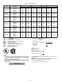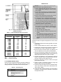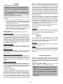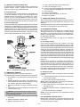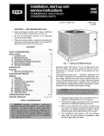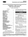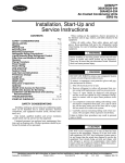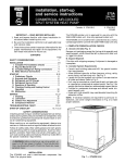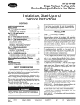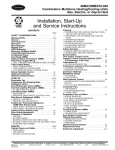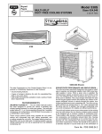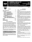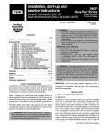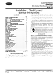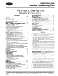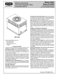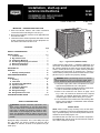
1
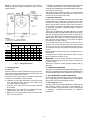
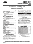
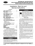
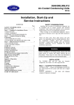
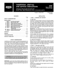
installation, start-up and
service instructions
569C
576B
COMMERCIAL AIR-COOLED
CONDENSING UNITS
Cancels: II 569C-72-3
II 569C-72-4
5/1/99
IMPORTANT —READ BEFORE INSTALLING
1. Read and become familiar with these installation
instructions before installing this unit (Fig. 1).
2. Be sure the installation conforms to all applicable local
and national codes.
3. These instructions contain important information for the
proper maintenance and repair of this equipment. Retain these instructions for future use.
CONTENTS
Page
SAFETY CONSIDERATIONS . . . . . . . . . . . . . . . . . . . . . . . 1
INSTALLATION . . . . . . . . . . . . . . . . . . . . . . . . . . . . . . . . . 1-9
I. Locate the Unit . . . . . . . . . . . . . . . . . . . . . . . . . . . . 2
II. Rig and Place Unit . . . . . . . . . . . . . . . . . . . . . . . . . 2
III. Compressor Mounting . . . . . . . . . . . . . . . . . . . . . . 2
IV. Unit Refrigerant Piping Connections . . . . . . . . . . 2
V. Electrical Connections . . . . . . . . . . . . . . . . . . . . . . 6
VI. Accessory Installation . . . . . . . . . . . . . . . . . . . . . . 9
PRE-START-UP . . . . . . . . . . . . . . . . . . . . . . . . . . . . . . . . . . 9
START-UP . . . . . . . . . . . . . . . . . . . . . . . . . . . . . . . . . . . . . 10
I. Start-Up and Adjustments . . . . . . . . . . . . . . . . . . 10
CARE AND MAINTENANCE . . . . . . . . . . . . . . . . . . . . . . 10
SERVICE . . . . . . . . . . . . . . . . . . . . . . . . . . . . . . . . . . . . . 11-13
I. Cleaning . . . . . . . . . . . . . . . . . . . . . . . . . . . . . . . . 11
II. Lubrication . . . . . . . . . . . . . . . . . . . . . . . . . . . . . . 11
III. Condenser-Fan Adjustment . . . . . . . . . . . . . . . . 11
IV. Capacity Control . . . . . . . . . . . . . . . . . . . . . . . . . . 12
V. Compressor Removal . . . . . . . . . . . . . . . . . . . . . 12
VI. Crankcase Heater . . . . . . . . . . . . . . . . . . . . . . . . . 12
VII. Refrigerant Charge . . . . . . . . . . . . . . . . . . . . . . . . 12
VIII. Refrigerant Service Ports . . . . . . . . . . . . . . . . . . . 12
TROUBLESHOOTING GUIDE . . . . . . . . . . . . . . . . . . . . 14,15
SAFETY CONSIDERATIONS
WARNING: Improper installation, adjustment, alteration, service, maintenance, or use can cause explosion, fire, electric shock, or other occurrences which may
injure you or damage your property. Consult a qualified installer or service agency for information or assistance. The qualified installer or agency must use only
factory-authorized kits or accessories when repairing this
product.
Recognize safety information. This is the safety-alert symbol. (
) When you see this symbol on the unit and in
instructions or manuals, be alert to the potential for personal injury.
Fig. 1 — Typical Unit (569C072 Shown)
Understand the signal words — DANGER, WARNING, and
CAUTION. These words are used with the safety-alert symbol. Danger identifies the most serious hazards which will
result in severe personal injury or death. Warning indicates
a condition that could result in personal injury. Caution is
used to identify unsafe practices which would result in minor
personal injury or product and property damage.
WARNING: Before performing service or maintenance operations on unit, turn off main power switch
to unit. Electrical shock could cause personal injury.
1. The power supply (volts, hertz, and phase) must correspond to that specified on unit rating plate.
2. The electrical supply provided by the utility must be sufficient to handle load imposed by this unit.
3. Refer to the Locate the Unit section on page 2 and
Fig. 2 and 3 for locations of electrical inlets, required
clearances, and weight distribution based on recommended support points before setting unit in place.
4. This installation must conform with local building codes.
Refer to local plumbing or wastewater codes and other
applicable local codes.
INSTALLATION
NOTE: When installing any accessory item, see the manufacturer’s installation instructions packaged with the accessory. A qualified agency must use factory-authorized kits or
accessories when modifying this unit.
The 569C072,090, and 120 units use hermetic compressors.
The 576B090,102, and 120 units use semi-hermetic compressors. Refer to Tables 1A and 1B.
NOTE: If vibration isolators are required for a particular installation, use corner weight information in Fig. 2 to make
proper selection.
f. Between unit and block or concrete walls and other grounded
surfaces, control box side, 42 in. (1067 mm) per NEC.
Although unit is weatherproof, guard against water from higher
level runoff and overhangs.
Slab-mounted units should be at least 4 in. (102 mm) above
the highest expected water level (flood and runoff). Do not
use the unit if it has been under water.
II. RIG AND PLACE UNIT
Inspect unit for transportation damage. File any claim with
transportation agency. Keep unit upright and do not drop.
Spreader bars are not required if top crating is left on unit.
Rollers may be used to move unit across a roof. Level by using unit frame as a reference. See Tables 1A and 1B and Fig. 4
for additional information. Operating weight is shown in
Tables 1A and 1B.
These units are designed for overhead rigging only. Rig with
packaging assembly and wood bumper strips in place to prevent unit damage by rigging cable. As further protection for
coil faces, plywood sheets may be placed against sides of unit,
behind cables. Run cables to a central suspension point so
that angle from the horizontal is not less than 45 degrees.
Raise and set unit down carefully.
If it is necessary to roll unit into position, mount unit on longitudinal rails, using a minimum of 3 rollers. Apply force to
rails, not unit. If unit is to be skidded into position, place it
on a large pad and drag it by the pad. Do not apply any force
to unit.
Raise from above to lift unit from rails or pad when unit is in
final position.
Lifting holes are provided in base rails as shown in Fig. 4.
Refer to rigging instructions on unit.
IMPORTANT: If unit has forklift protection skids, be sure to
remove forklift protection skids from under unit before setting unit in place.
After unit is in position, remove shipping materials and rigging skids.
NOTES:
1. Dimensions in [ ] are in millimeters.
2. See Fig. 3 for additional information.
UNIT
569C072
569C090
569C120
576B090
576B102
576B120
Std Unit
Lb
340
370
395
510
564
564
Kg
154
168
179
231
256
256
WEIGHT CHART*
Corner
Corner
Corner
W
X
Y
Lb Kg Lb Kg Lb Kg
86 39 53 24
77 35
86 39 78 35
99 45
89 40 92 42 109 49
115 52 89 40 133 60
133 50 97 44 141 64
133 60 97 44 141 64
Corner
Z
Lb Kg
124 56
107 49
105 48
173 87
193 88
193 88
*Weights are for aluminum coils.
Fig. 2 — Weight Distribution
I. LOCATE THE UNIT
III. COMPRESSOR MOUNTING
Compressors are shipped from the factory held down by 4 bolts.
After unit is installed, loosen each bolt until the snubber washer
can be moved with finger pressure (376B units only). See Fig. 5.
A. Clearance
Maintain clearance around and above unit to provide minimum distance from combustible materials, proper airflow, and
service access. Refer to Fig. 2 and 3.
Minimum clearance (local codes or jurisdiction may prevail):
a. Bottom to combustible surfaces 0 inches.
b. Condenser coil, for proper airflow, 36 in. (914 mm) one side,
12 in. (305 mm) the other. The left or rear side receiving
the greater clearance is optional.
c. Overhead, 60 in. (1524 mm) to ensure proper condenser
fan operation.
d. Between units, control box side, 42 in. (1067 mm) per NEC
(National Electrical Code, U.S.A. Standard).
e. Between unit and ungrounded surfaces, control box side,
36 in. (914 mm) per NEC.
IV. UNIT REFRIGERANT PIPING CONNECTIONS
Suction connection is sweat with plastic cap; liquid connection is sweat with plastic cap. Refer to Table 2 for refrigerant
piping sizes. Follow standard piping practices.
A. Size Refrigerant Lines
Consider length of piping required between condensing unit
and evaporator, amount of liquid lift, and compressor oil
return. See Table 3 for design details and line sizing. Refer
to evaporator installation instructions for additional
information.
—2—
Table 1A — Specifications (English)
UNIT
NOMINAL CAPACITY (Tons)
OPERATING WEIGHT (lb)
Aluminum Coils (Standard)
Copper Coils (Optional)
RIGGING WEIGHT (lb)
Aluminum Coils (Standard)
Copper Coils (Optional)
REFRIGERANT*
COMPRESSOR
Quantity...Type
Quantity Cylinders
Speed (Rpm)
Oil Charge (oz) (ea)
CONDENSER FAN
Quantity...Rpm
Diameter (in.)
Motor Hp (NEMA)
Nominal Airflow (cfm)
CONDENSER COIL
Face Area (sq ft)
Storage Capacity (lb)†
CONNECTIONS (sweat)
Suction (in.)
Liquid (in.)
CONTROLS
Pressurestat Settings (psig)
High Cutout
Cut-in
Low Cutout
Cut-in
569C072
6
569C090
71⁄2
569C120
10
576B090
71⁄2
576B102
81⁄2
576B120
10
340
386
370
438
395
472
510
578
564
632
564
632
390
436
420
488
Bristol, Reciprocating
1...H26A72Q
2
3500
65
1...850
26
1⁄3
3800
12.24
11.26
11⁄8
1⁄2
445
560
614
614
522
628
682
682
R-22
Copeland, Scroll Copeland, Scroll
Reciprocating, Semi-Hermetic
1...ZR94KC
1...ZR125KC
1...06DA818 1...06DA824 1...06DH824
(See Note)
—
—
4
6
3500
3500
1750
1750
85
110
88
128
Propeller; Direct Drive
1...1100
26
3 ⁄4
6500
7000
6500
6500
6500
Enhanced Copper Tubes, Aluminum Lanced Fins
15.75
20.5
18.0
18.0
18.0
14.88
18.87
16.56
16.56
16.56
11⁄8
1 ⁄2
11⁄8
5 ⁄8
11⁄8
1⁄2
11⁄8
5⁄8
11⁄8
5⁄8
426 6 7
320 6 20
76 3
22 6 5
LEGEND
NEMA — National Electrical Manufacturing Association
*Unit is factory supplied with holding charge only.
†Storage capacity of condenser coil with coil 80% full of liquid R-22 at
124 F.
NOTE: Unit 576B120 has one step of unloading. Full load is 100% capacity, and one step of unloading is 67% capacity. Unit 576B120 has
the following unloader settings: load is 70 6 1 psig and unload is
60 6 2 psig.
—3—
Table 1B — Specifications (SI)
UNIT
NOMINAL CAPACITY (kW)
OPERATING WEIGHT (kg)
Aluminum Coils (Standard)
Copper Coils (Optional)
RIGGING WEIGHT (kg)
Aluminum Coils (Standard)
Copper Coils (Optional)
REFRIGERANT*
COMPRESSOR
Quantity...Type
Quantity Cylinders
Speed (R/s)
Oil Charge (L) (ea)
CONDENSER FAN
Quantity...R/s
Diameter (mm)
Motor Hp (NEMA)
Nominal Airflow (L/s)
CONDENSER COIL
Face Area (sq m)
Storage Capacity (kg)†
CONNECTIONS (sweat)
Suction (in.)
Liquid (in.)
CONTROLS
Pressurestat Settings (kPa)
High Cutout
Cut-in
Low Cutout
Cut-in
569C072
21
569C090
26
569C120
35
576B090
26
576B102
29.9
576B120
35
154
175
168
199
179
214
231
262
256
287
256
287
176
198
191
221
254
285
279
309
279
309
Bristol, Reciprocating
1...H26A72Q
Copeland, Scroll
1...ZR94KC
202
237
R-22
Copeland, Scroll
1...ZR125KC
2
58.4
1.92
—
58.4
2.51
1...14.2
660
1⁄3
1800
1.14
5.1
11⁄8
1⁄2
Reciprocating, Semi-Hermetic
1...06DH824
1...06DA818 1...06DA824 (See
Note 1)
—
4
58.4
29.2
3.25
2.60
Propeller; Direct Drive
1...18.3
660
3 ⁄4
3050
3300
3050
Enhanced Copper Tubes, Aluminum Lanced Fins
1.46
1.90
1.67
6.75
8.6
7.5
11⁄8
1 ⁄2
11⁄8
5 ⁄8
11⁄8
1⁄2
6
29.2
3.78
3050
3050
1.67
7.5
1.67
7.5
11⁄8
5⁄8
11⁄8
5 ⁄8
2937 6 48
2206 6 138
48 6 20
152 6 34
LEGEND
NEMA — National Electrical Manufacturing Association
*Unit is factory supplied with holding charge only.
†Storage capacity of condenser coil with coil 80% full of liquid R-22 at
51 C.
NOTES:
1. Unit 576B120 has one step of unloading. Full load is 100% capacity,
and one step of unloading is 67% capacity. Unit 576B120 has the
following unloader settings: load is 483 6 6.9 kPa and unload is
414 6 13.8 kPa.
2. Equivalent mm values for connectors are as follows:
in.
mm
⁄
⁄
11⁄8
12
58
—4—
12.7
15.9
28.6
UNIT DIM. A
18-61⁄29
569C072 [470.0]
18-89
569C090
[508.0]
18-99
569C120
[533.4]
18-69
576B090
[457.2]
18-79
576B102
[482.6]
18-79
576B120
[482.6]
DIM. B
18-23⁄49
[375.0]
18-61⁄29
[470.0]
18-89
[508.0]
18-43⁄49
[425.5]
18-59
[431.8]
18-59
[431.8]
DIM. C DIM. D
—
18-21⁄49
—
[362]
—
18-39
—
[381]
28-09
18-39
[609.6] [381]
28-913⁄169 18-39
[858.8] [381]
28-913⁄169 18-39
[858.8] [381]
28-913⁄169 18-39
[858.8] [381]
DIM. E
18-45⁄169
[415]
28-5⁄169
[613]
28-5⁄169
[613]
28-5⁄169
[613]
28-5⁄169
[613]
28-5⁄169
[613]
DIM. F
28-95⁄169
[846.5]
38-57⁄169
[1052.5]
38-57⁄169
[1052.5]
38-57⁄169
[1052.5]
38-57⁄169
[1052.5]
38-57⁄169
[1052.5]
3.
Std Unit Corner W Corner X Corner Y Corner Z
Lb Kg Lb
569C072 340 154 86
569C090 370 168 86
569C120 395 179 89
576B090 510 231 115
576B102 564 256 133
576B120 564 256 133
*Weights are for aluminum
NOTES:
1. Dimensions in [ ] are in millimeters.
2.
ELECTRICAL CONNECTIONS
WEIGHT CHART*
UNIT
Center of Gravity. See chart for dimensions.
Direction of Airflow.
4. Minimum clearance (local codes or jurisdiction may prevail):
a. Condenser coil, for proper airflow, 36 in. [914] one side, 12 in. [305]
the other. The left or rear side getting the greater clearance is optional.
b. Overhead, 60 in. [1524] to assure proper condenser fan operation.
Kg Lb
39 53
39 78
40 92
52 89
60 97
60 97
coils.
Kg
24
35
42
40
44
44
Lb
77
99
109
133
141
141
Kg
35
45
49
60
64
64
Lb
124
107
105
173
193
193
CONNECTION SIZES
Kg
56
49
48
87
88
88
AA
BB
CC
DD
13⁄89 DIA [35] FIELD POWER SUPPLY HOLE
29 DIA [51] POWER SUPPLY KNOCK-OUT
21⁄29 DIA [64] POWER SUPPLY KNOCK-OUT
7⁄89 DIA [22] FIELD CONTROL WIRING HOLE
SERVICE VALVE CONNECTIONS — 60 Hz
UNIT
569C072
569C090
569C120
576B090
576B102
576B120
c. Between units, control box side, 42 in. [1067]
per NEC (National Electrical Code) (U.S.A.
Standard).
d. Between unit and ungrounded surfaces, control box side, 36 in. [914] per NEC.
e. Between unit and block or concrete walls and
other grounded surfaces, control box side,
42 in. [1067] per NEC.
5. With the exception of the clearance for the condenser coil as stated in note 4b, a removable
fence or barricade requires no clearance.
6. Units may be installed on combustible floors made
from wood or Class A, B, or C roof covering
material.
SUCTION
11⁄89 [28.6]
11⁄89 [28.6]
11⁄89 [28.6]
11⁄89 [28.6]
11⁄89 [28.6]
11⁄89 [28.6]
LIQUID
⁄ 9 [12.7]
1⁄29 [12.7]
5⁄89 [15.9]
1⁄29 [12.7]
5⁄89 [15.9]
5⁄89 [15.9]
12
Fig. 3 — Base Unit Dimensions
UNIT
569C072
569C090
569C120
576B090
576B102
576B120
RIGGING WEIGHT*
lb
390
420
445
560
614
614
kg
176
191
202
254
279
279
*Weights are for aluminum coils.
Fig. 4 — Rigging Label
—5—
A
in.
45.0
45.0
45.0
45.0
45.0
45.0
B
mm
1143
1143
1143
1143
1143
1143
in.
38.5
38.5
38.5
38.5
38.5
38.5
C
mm
978
978
978
978
978
978
in.
35.5
43.5
43.5
43.5
43.5
43.5
mm
904
1105
1105
1105
1105
1105
Table 3 — Liquid Line Data
UNIT
569C072
569C090
569C120
576B090
576B102
576B120
Fig. 5 — Typical Compressor Mounting (576B Units)
WARNING: The unit cabinet must have an uninterrupted, unbroken electrical ground to minimize the possibility of personal injury if an electrical fault should
occur. This ground may consist of electrical wire connected to the unit ground lug in the control compartment or conduit approved for electrical ground when
installed in accordance with the NEC and local electrical codes. Failure to adhere to this warning could result in personal injury.
CAUTION: Failure to follow these precautions could
result in damage to the unit being installed:
A. Field Power Supply (Fig. 6-8)
1. Make all electrical connections in accordance with NEC
ANSI/NFPA (American National Standards Institute/
National Fire Protection Association) 70, latest edition,
and local electrical codes governing such wiring. Refer
to unit wiring diagram.
2. Use only copper or copper-clad conductor fan connections between field-supplied electrical disconnect switch
and unit. DO NOT USE ALUMINUM WIRE. Maximum
wire size is no. 2 AWG (American Wire Gage).
3. Voltage to compressor terminals during operation must
be within voltage range indicated on unit nameplate (also
see Table 4). On 3-phase units, voltages between phases
must be balanced within 2% and the current within 10%.
Use the formula shown in Table 4, Note 2, to determine
the percent voltage imbalance. Operation on improper
line voltage or excessive phase imbalance constitutes abuse
and may cause damage to electrical components. Such
operation would invalidate any applicable warranty.
4. Insulate low-voltage wires for highest voltage contained within conduit when low-voltage control wires are
run in same conduit as high-voltage wires.
5. Do not damage internal components when drilling through
any panel to mount electrical hardware, conduit, etc.
Table 2 — Refrigerant Piping Sizes
569C072
569C090
569C120
576B090
576B102
576B120
75-100
(22.9-30.5)
L
⁄
5 ⁄8
5 ⁄8
5 ⁄8
5 ⁄8
5 ⁄8
12
S
11⁄8
13⁄8
13⁄8
13⁄8
13⁄8
13⁄8
LEGEND
L — Liquid Line S — Suction Line
NOTES:
1. Pipe sizes are based on a 2° F (1° C) loss for liquid and suction
lines.
2. Pipe sizes are based on the maximum linear length shown for each
column, plus a 50% allowance for fittings.
3. Charge units with R-22 in accordance with unit installation instructions.
4. Line size conversion to mm is:
in.
mm
⁄
⁄
11⁄8
13⁄8
12
58
M
26.2
18.3
21.3
18.3
19.8
19.8
V. ELECTRICAL CONNECTIONS
The filter drier is factory installed. Moisture indicator is a
field-installed accessory and should be installed just after liquid line shutoff valve. Do not use a receiver. A receiver is not
supplied with the unit and should not be used.
NOTE: Unit is shipped with R-22 holding charge. System pressure must be relieved before removing caps. Recover refrigerant prior to brazing.
Pass nitrogen or other inert gas through piping while brazing to prevent formation of copper oxide.
Install field-supplied thermostatic expansion valve(s) in evaporator section. It is recommended that a field supplied liquid line solenoid be positioned in the main liquid line (near
the evaporator coil). It should be wired to close when compressor stops to minimize refrigerant migration during the
‘‘OFF’’ cycle.
UNIT
Ft
86
60
70
60
65
65
LIQUID LINE
Max Allowable
Max Allowable
Pressure Drop
Temp Loss
psi
kPa
F
C
7
48.3
2
1
7
48.3
2
1
7
48.3
2
1
7
48.3
2
1
7
48.3
2
1
7
48.3
2
1
NOTE: Values shown are for units operating at 45 F (7.2 C) saturated
suction and 95 F (35 C) entering air.
B. Filter Drier and Moisture Indicator
LINEAR LENGTH OF PIPING — FT (M)
0-25
25-50
50-75
(0-7.6)
(7.6-15.2)
(15.2-22.9)
Line Size (in. OD)
L
S
L
S
L
S
1⁄2
1⁄2
1⁄2
11⁄8
11⁄8
11⁄8
1⁄2
1⁄2
5⁄8
11⁄8
11⁄8
11⁄8
5⁄8
5⁄8
5⁄8
11⁄8
13⁄8
13⁄8
1⁄2
1⁄2
5⁄8
11⁄8
11⁄8
11⁄8
5⁄8
1
1
5
5
1 ⁄8
⁄8
1 ⁄8
⁄8
13⁄8
5⁄8
5⁄8
5⁄8
11⁄8
11⁄8
13⁄8
MAX
ALLOWABLE
LIQUID LIFT
12.7
15.9
28.6
34.9
—6—
All units except 208/230-v units are factory wired for the voltage shown on the nameplate. If the 208/230-v unit is to be
connected to a 208-v power supply, the transformer must be
rewired by moving the black wire from the 230-v orange wire
on the transformer and connecting it to the 200-v red wire
from the transformer. The end of the orange wire must then
be insulated.
Refer to unit label diagram for additional information. Pigtails are provided for field wire connections. Use factorysupplied splices or UL (Underwriters’ Laboratories) approved
copper/aluminum connector.
When installing units, provide a disconnect per NEC.
All field wiring must comply with NEC and local
requirements.
Install field wiring as follows:
1. Install conduit through side panel openings.
2. Install power lines to terminal connections as shown in
Fig. 6.
B. Control Voltage Connections
Install an accessory thermostat assembly according to installation instructions included with the accessory. Locate thermostat assembly on a solid wall in the conditioned space to
sense average temperature in accordance with thermostat
installation instructions.
Route thermostat cable or equivalent single leads of colored
wire from subbase terminals to low-voltage connections on
unit (shown in Fig. 7) as described in Steps 1 through 4
below.
NOTE: Refer to Table 5 for wire conversion information.
NOTE: For wire runs up to 50 ft (15.2 m), use no. 18 AWG
(0.82 mm) insulated wire (35 C minimum). For 50 to 75 ft
(15.2 to 22.9 m), use no. 16 AWG (1.30 mm) insulated wire
(35 C minimum). For over 75 ft (22.9 m), use no. 14 AWG
(2.08 mm) insulated wire (35 C minimum). All wire larger
than no. 18 AWG (0.82 mm) cannot be directly connected to
the thermostat and will require a junction box and splice at
the thermostat.
1. Connect thermostat wires to screw terminals of low voltage connection board.
2. Pass the control wires through the hole provided in the
corner post. See Fig. 8.
3. Feed wire through raceway built into the corner post
and into the 24-v thermostat connection board. The 24-v
thermostat connection is located on the left side of the
low voltage connection compartment. The raceway provides the UL required clearance between the high- and
low-voltage wiring.
4. Total combined amperage draw of the field-installed liquid line solenoid valve and indoor fan contactor must
not exceed 22 va. If the specified va must be exceeded,
use a remote relay to switch the load.
LEGEND
C
— Contactor
NEC — National Electrical Code (U.S.A. Standard)
Field Wiring
Factory Wiring
Splice Connection (Factory Supplied)
Fig. 6 — Power Wiring Connections
AHA
C
CB
CC
CLO
HPS
IFC
—
—
—
—
—
—
—
Adjustable Heat Anticipator
Contactor, Compressor
Circuit Breaker
Cooling Compensator
Compressor Lockout
High-Pressure Switch
Indoor (Evaporator) Fan Contactor
LLSV
LPS
TB
TC
TDR
TH
TRAN
—
—
—
—
—
—
—
LEGEND
Liquid Line Solenoid Valve
Low-Pressure Switch
Terminal Block
Thermostat-Cooling
Time-Delay Relay
Thermostat-Heating
Transformer
Terminal (Marked)
Splice
Factory Wiring
Field Control Wiring
To Indicate Common Potential Only,
Not To Represent Wiring
Fig. 7 — Typical Control Wiring Connections (569C Shown)
—7—
Table 4 — Electrical Data
NOMINAL VOLTAGE
(V-Ph-Hz)
UNIT
569C072
569C090
569C120
576B090
576B102
576B120
CSA
FLA
HACR
LRA
MCA
MOCP
NEC
OFM
RLA
UL
—
—
—
—
—
—
—
—
—
—
208/230-3-60
460-3-60
575-3-60
220-3-50
400-3-50
208/230-3-60
460-3-60
575-3-60
220-3-50
400-3-50
208/230-3-60
460-3-60
575-3-60
220-3-50
400-3-50
208/230-3-60
380-3-60
460-3-60
575-3-60
220-3-50
400-3-50
208/230-3-60
380-3-60
460-3-60
575-3-60
220-3-50
400-3-50
208/230-3-60
380-3-60
460-3-60
575-3-60
220-3-50
400-3-50
VOLTAGE RANGE
Min
Max
187
254
414
508
518
632
198
242
360
440
187
254
414
508
518
632
198
242
360
440
187
254
414
508
518
632
198
242
360
440
187
254
342
418
414
508
518
632
198
253
342
460
187
254
342
418
414
508
518
632
198
253
342
460
187
254
342
418
414
508
518
632
198
253
342
460
LEGEND
Canadian Standards Association
Full Load Amps
Heating, Air Conditioning and Refrigeration
Locked Rotor Amps
Minimum Circuit Amps
Maximum Overcurrent Protection
National Electrical Code (U.S.A. Standard)
Outdoor (Condenser) Fan Motor
Rated Load Amps
Underwriters’ Laboratories
COMPRESSOR
RLA
LRA
21.8
142
9.6
72
7.6
58
19.0
142
9.5
72
28.8
195
14.7
95
10.8
80
28.8
195
14.7
90
37.8
239
17.2
125
12.3
80
37.8
239
17.2
114
31.5
160
19.0
75
15.7
80
12.6
64
31.5
160
15.7
80
39.7
198
24.0
93
19.9
99
15.9
79
39.7
198
19.9
99
39.7
198
24.0
93
19.9
99
15.9
79
39.7
198
19.9
99
OFM
FLA
1.9
1.0
1.9
1.0
1.0
3.8
1.9
1.9
1.5
1.5
3.1
1.4
1.4
1.4
1.4
3.1
2.2
1.4
1.4
1.4
1.4
3.1
2.2
1.4
1.4
1.4
1.4
3.1
2.2
1.4
1.4
1.4
1.4
POWER SUPPLY
MCA
MOCP
25.6
35
12.9
15
11.4
15
25.6
35
12.9
15
39.8
45
20.3
20
15.4
15
37.5
45
19.9
20
46.2
60
22.7
30
19.3
25
46.2
60
22.7
30
42.5
50
26.0
35
21.0
25
17.2
20
42.5
50
21.0
25
52.7
70
32.2
40
26.3
35
21.3
25
52.7
70
26.3
35
52.7
70
32.2
40
26.3
35
21.3
25
52.7
70
26.3
35
Example: Supply voltage is 460-3-60.
AB = 452 v
BC = 464 v
AC = 455 v
452 + 464 + 455
Average Voltage =
3
1371
=
3
= 457
(AB) 457 - 452 = 5 v
(BC) 464 - 457 = 7 v
(AC) 457 - 455 = 2 v
Maximum deviation is 7 v.
Determine percent voltage imbalance
7
% Voltage Imbalance = 100 x
457
= 1.53%
This amount of phase imbalance is satisfactory as it is below the maximum allowable 2%.
IMPORTANT: If the supply voltage phase imbalance is more than 2%,
contact your local electric utility company immediately.
NOTES:
1. In compliance with NEC requirements for multimotor and combination load equipment (refer to NEC Articles 430 and 440), the overcurrent protective device for the unit shall be fuse or HACR breaker.
2. Unbalanced 3-Phase Supply Voltage
Never operate a motor where a phase imbalance in supply voltage is
greater than 2%. Use the following formula to determine the percent
voltage imbalance.
max voltage deviation from average voltage
= 100 x
average voltage
3. The 575-v units are CSA only.
4. The 380-v units are not UL or CSA listed.
—8—
PRE-START-UP
WARNING: Failure to observe the following warnings could result in serious personal injury:
1. Follow recognized safety practices and wear protective goggles when checking or servicing refrigerant system.
2. Do not operate compressor or provide any electric
power to unit unless compressor terminal cover is
in place and secured.
3. Do not remove compressor terminal cover until all
electrical sources have been disconnected.
4. If refrigerant leak is suspected around compressor terminals, recover refrigerant whenever possible and relieve all pressure from system before
touching or disturbing anything inside terminal box.
5. Never attempt to repair soldered connection while
refrigerant system is under pressure.
6. Do not use torch to remove any component. System contains oil and refrigerant under pressure.
To remove a component, wear protective goggles
and proceed as follows:
a. Shut off electrical power to unit.
b. Recover refrigerant. Relieve all pressure from
system.
c. Cut component-connecting tubing with tubing
cutter and remove component from unit.
d. Carefully unsweat remaining tubing stubs when
necessary. Oil can ignite when exposed to torch
flame.
Fig. 8 — Field Control Wiring Raceway
(576B Unit Shown)
Table 5 — American/European Wire Conversions
AMERICAN
Industry
Standard Size
18 AWG
16 AWG
14 AWG
12 AWG
10 AWG
8 AWG
6 AWG
4 AWG
3 AWG
2 AWG
1 AWG
1/0 AWG
2/0 AWG
3/0 AWG
4/0 AWG
250 kcmil
300 kcmil
350 kcmil
400 kcmil
500 kcmil
600 kcmil
American
Conversion
(mm2)
0.82
1.30
2.08
3.30
5.25
6.36
13.29
21.14
26.65
33.61
42.39
53.49
67.42
85.00
107.19
126.64
151.97
177.90
202.63
253.29
303.95
EUROPEAN
Industry
Standard
Size (mm2)
1.0
1.5
2.5
4.0
6.0
10.0
16.0
25.0
—
35.0
50.0
—
70.0
95.0
120.0
150.0
—
185.0
240.0
300.0
—
Proceed as follows to inspect and prepare the unit for initial
start-up:
1. Field electrical power source must agree with unit nameplate rating.
2. Check voltage imbalance as shown in Table 4, Note 2.
3. Check that all internal wiring connections are tight and
that all barriers, covers, and panels are in place.
4. Ensure all service valves are open. On 576B units, be
sure all compressor service valves are backseated.
5. Verify that compressor holddown bolts have been loosened and that flat/snubber washers can be rotated by
applying finger pressure (snug, but not tight).
6. On 569C and 576B units, verify compressor crankcase
heater is securely in place. Crankcase heater must operate for a least 24 hours before start-up.
LEGEND
AWG — American Wire Gage
kcmil — Thousand Circular Mils
7. Note that compressor oil level is visible in the sight
glass (576B units only).
VI. ACCESSORY INSTALLATION
At this time any required accessories should be installed on
the unit. Refer to Table 6 for available accessories. Control
wiring information is provided in the unit wiring book.
8. Check for leaks in refrigerant system by using soap
bubbles and/or electronic leak detector.
9. Check that liquid line solenoid valve is located at evaporator coil as shown in Filter Drier and Moisture Indicator section, page 6.
Table 6 — Accessory List
10. Check that both outdoor and indoor units are properly
mounted in accordance with installation instructions
and applicable codes.
ACCESSORY
Gage Panel
Winter-Start Relay Package
Weatherprobe™ II Low Ambient Kit
Hail Guard Package (072)
Hail Guard Package (090,102,120)
Thermostats
Subbase
—9—
Terminals G and C) will also open, allowing the system to
function in cooling. As cooling demand is satisfied, the thermostat contacts break, deenergizing the contactor causing the
system to shut off. The liquid line solenoid (LLS) valve closes,
minimizing the potential for refrigerant migration at this time.
The compressor does not restart until the thermostat again
calls for cooling. If a demand for cooling occurs within 5 minutes after the thermostat is satisfied, the system will not restart due to the feature of Time Guard II device. After the
5-minute time period, the system will restart as normal upon
thermostat demand.
START-UP
I. START-UP AND ADJUSTMENTS
CAUTION: Complete the required procedures given
in the Pre-Start-Up section before starting the unit.
Do not jumper any safety devices when operating the
unit.
Do not operate the compressor when the outdoor temperature is below 25 F (24 C) (unless accessory low ambient kit is installed).
A. Checking Cooling Control Operation
Start and check the unit for proper cooling control operation
as follows:
1. Place room thermostat SYSTEM switch in OFF position. Observe that blower motor starts when FAN switch
is placed in ON position and shuts down when FAN switch
is placed in AUTO. position.
2. Place SYSTEM switch in COOL position and FAN switch
in AUTO. position. Set cooling control below room temperature. Observe that compressor and condenser- and
evaporator-fan motors start. Observe that cooling cycle
shuts down when control setting is satisfied.
B. Unit Controls
All units have the following internal-protection controls:
Compressor Overload
This overload interrupts power to the compressor when
either the current or internal motor winding temperature become excessive, and automatically resets when the internal
temperature drops to a safe level. This overload may require
up to 60 minutes (or longer) to reset. If the internal overload
is suspected of being open, disconnect the electrical power to
the unit and check the circuit through the overload with an
ohmmeter or continuity tester.
Time Guardt II Device
The unit is equipped with accessory Time Guard II recycle
timer. The device will cause a 5-minute delay between compressor starts.
Cycle-LOC™ Device
When high-pressure or low-pressure fault occurs, the CycleLOC device will protect the system by not allowing the compressor to start.
Low-Pressure/Loss of Charge Switch (LPS)
When the liquid line pressure drops below 7 psig (48 kPa),
the LPS opens 24-v power to the compressor contactor and
stops the compressor. When the pressure reaches 22 psig
(152 kPa), the switch resets and the compressor is allowed to
restart.
High-Pressure Switch (HPS)
When the refrigerant high-side pressure reaches 426 psig
(2937 kPa), the HPS opens 24-v power to the compressor contactor and stops the compressor. When the pressure drops to
320 psig (2206 kPa), the switch resets and the compressor is
allowed to restart.
The system is protected with a Cycle-LOC device so that the
compressor will not start if a high-pressure or low-pressure
fault occurs. To reset the Cycle-LOC device, set the thermostat to eliminate the cooling demand then return to the original set point. This should be done only once, and if system
shuts down due to the same fault, determine the problem before attempting to reset the Cycle-LOC device.
The crankcase heaters must be energized for a minimum of
24 hours before starting a 569C and 576B unit.
D. Oil Charge
576B Units
Allow unit to run for about 20 minutes. Stop unit and check
compressor oil level. Add oil only if necessary to bring oil into
view in sight glass. Use only approved compressor oil.
Approved oils are:
Suniso 3GS
WF32-150
If oil is added, run unit for an additional 10 minutes. Stop
unit and check oil level. If level is still low, add oil only after
determining that piping system is designed for proper oil return and that system is not leaking oil.
569C Units
The 569C units do not have a sight glass and are factory charged
with the correct amount of oil.
All Units
Do not reuse drained oil or use any oil that has been exposed
to the atmosphere. Procedures for adding or removing oil are
given in the Standard Service Techniques Manual, Chapter 1,
Refrigerants.
CARE AND MAINTENANCE
To ensure continuing high performance and to minimize the
possibility of premature equipment failure, periodic maintenance must be performed on this equipment. This cooling unit
should be inspected at least once each year by a qualified service person.
NOTE TO EQUIPMENT OWNER: Consult your local dealer
about the availability of a maintenance contract.
C. Sequence of Operation
At start-up, the thermostat calls for cooling. When all safety
devices are satisfied, the compressor contactor (fan contactor) will energize causing the compressor and outdoor (condenser) fan motor to operate. Terminal 9G9 at the thermostat
is also energized, allowing the field-supplied and -installed
(24v) indoor (evaporator) fan contactor to function. A fieldsupplied and -installed liquid line valve (connected between
—10—
WARNING: The ability to properly perform maintenance on this equipment requires certain expertise,
mechanical skills, tools, and equipment. If you do not
possess these, do not attempt to perform any maintenance on this equipment other than those procedures
recommended in the User’s Manual. FAILURE TO HEED
THIS WARNING COULD RESULT IN SERIOUS PERSONAL INJURY AND POSSIBLE DAMAGE TO THIS
EQUIPMENT.
SERVICE
WARNING: When servicing unit, shut off all electrical power to unit to avoid shock hazard or injury from
rotating parts.
I. CLEANING
Inspect unit interior at the beginning of each cooling season
and as operating conditions require.
A. Condenser Coil
Inspect coil monthly. Clean condenser coil annually, and as
required by location and outdoor-air conditions.
Clean coil as follows:
1. Turn off unit power.
2. Remove and save top panel screws on condensing unit.
3. Remove condenser coil corner post. See Fig. 9. To hold
top panel open, place coil corner post between top panel
and side panel. See Fig. 10.
4. Remove bracket holding coil sections together at return
end of condenser coil. Carefully separate the outer coil
section 3 to 4 in. (75 to 100 mm) from the inner coil section. See Fig. 11.
5. Use a water hose or other suitable equipment to flush
down between the 2 coil sections to remove dirt and
debris. Clean the outer surfaces with a stiff brush in the
normal manner.
6. Reposition the outer coil section, attach the bracket removed in Step 4, and remove the coil corner post from
between the top panel and side panel. Secure the sections together. Install the coil corner post and replace
all screws (removed in Step 2).
Fig. 10 — Propping Up Top Panel
II. LUBRICATION
A. Compressors
Each compressor is charged with the correct amount of oil at
the factory. Refer to the Oil Charge section on page 10 for additional information.
B. Fan Motor Bearings
Fan motor bearings are of the permanently-lubricated type.
No further lubrication is required.
Fig. 9 — Cleaning Condenser Coil
Fig. 11 — Separating Coil Sections
III. CONDENSER-FAN ADJUSTMENT (Fig. 12)
1. Shut off unit power supply.
2. Remove condenser-fan assembly (grille, motor, motor cover,
and fan).
3. Loosen fan hub setscrews.
4. Adjust fan height as shown in Fig. 12.
5. Tighten set screws.
6. Replace condenser-fan assembly.
NOTE: Fan height adjustments are as follows:
UNIT
569C072
All Units
(except 569C072)
in.
4.50
mm
114
6.42
163
Fig. 12 — Outdoor (Condenser) Fan Adjustment
—11—
8. Clean system. Add new liquid line filter drier.
9. Install new compressor in unit.
IV. CAPACITY CONTROL (576B120 Only)
A suction pressure-actuated unloader controls 2 cylinders and
provides capacity control. Unloaders are factory set (see
Table 1A or 1B), but may be field adjusted:
A. Control Set Point
The control set point (cylinder load point) is adjustable from
0 to 85 psig (586 kPa). To adjust, turn control set point adjustment nut (Fig. 13) clockwise to its bottom stop. In this
position, set point is 85 psig (586 kPa). Then, turn adjustment counterclockwise to desired control set point. Every full
turn counterclockwise decreases set point by 7.5 psig (51.7 kPa).
B. Pressure Differential
The pressure differential (difference between cylinder load and
unload points) is adjustable from 6 to 22 psig (41.4 to 152 kPa).
To adjust, turn pressure differential adjustment screw (Fig. 13)
counterclockwise to its back stop position. In this position,
differential is 6 psig (41.4 kPa). Then, turn adjustment screw
clockwise to desired pressure differential. Every full turn clockwise increases differential by 1.5 psig (10.3 kPa).
10. Connect suction and discharge lines to compressor. Ensure that compressor holddown bolts are in place.
11. Connect wiring.
12. Install crankcase heater.
13. Evacuate and recharge unit, per Step VII.
14. Restore unit power.
VI. CRANKCASE HEATER (Except 569C072)
The crankcase heater prevents refrigerant migration and compressor oil dilution during shutdown when compressor is not
operating.
Close both compressor service valves if applicable when crankcase heater is deenergized for more than 6 hours.
VII. REFRIGERANT CHARGE
Unit panels must be in place when unit is operating during
charging procedure. Unit is shipped with a holding charge
only. Weigh in 7 lbs (3 kg) of R-22 to start unit. Refer to GTAC II,
Module 5, Charging, Recovery, Recycling, and Reclamation
for additional information.
See Troubleshooting Guide on page 14 for additional
information.
A. Low Charge Cooling
Using Cooling Charging Charts, Fig. 14 and 15, vary refrigerant until the conditions of the appropriate chart are met.
Note the charging charts are different from type normally used.
The charts are based on charging the units to the correct subcooling for the various operating conditions. Accurate pressure gage and temperature sensing device are required. Connect the pressure gage to the service port on the liquid line
service valve. Mount the temperature sensing device on the
liquid line, close the liquid line service valve, and insulate it
so that outdoor ambient temperature does not affect the reading. Indoor-air cfm must be within the normal operating range
of the unit.
Operate unit a minimum of 15 minutes. Ensure that temperature and pressure have stabilized. Plot liquid pressure
and temperature on chart and add or reduce charge as required. Do not vent refrigerant to the atmosphere. Recover
any excess charge. Operate the unit until the system stabilizes. Adjust charge to conform with charging chart, using liquid pressure and temperature to read chart.
Fig. 13 — Compressor Capacity Control Unloader
V. COMPRESSOR REMOVAL
See Tables 1A and 1B for compressor information.
Follow safety codes and wear safety glasses and work gloves.
1. Shut off power to unit. Remove unit access panel (front
of unit).
2. Remove refrigerant from system using refrigerant removal methods described in GTAC II, Module 5, Charging, Recovery, Recycling, and Reclamation.
3. Disconnect compressor wiring at compressor terminal
box.
4. Remove bolts from suction flange and discharge service valve (576B Units).
CAUTION: Excessive movement of copper lines at
compressor may cause higher levels of vibration when
unit is restored to service.
5. Remove crankcase heater from compressor base (576B
units only).
6. Remove compressor holddown bolts.
7. Remove compressor from unit.
B. Refrigerant Leaks
Proceed as follows to repair a refrigerant leak and to charge
the unit:
1. Locate the leak and ensure that refrigerant system pressure has been relieved.
2. Repair leak following accepted practices.
NOTE: Install a new filter drier in the liquid line whenever
the system has been opened for repair.
3. Add a small charge of R-22 refrigerant vapor to system
and leak-test unit.
4. Evacuate refrigerant system if additional leaks are not
found.
5. Charge unit with R-22 refrigerant.
NOTE: Do not vent refrigerant to the atmosphere. Recover
any excess charge.
VIII. REFRIGERANT SERVICE PORTS
Each unit has 3 service ports: one on the suction line, one on
the liquid line, and one on the compressor discharge line. Be
sure caps on the ports are tight.
—12—
Fig. 15 — Cooling Charging Chart — 569C090,120
and 576B090,102,120
Fig. 14 — Cooling Charging Chart — 569C072
—13—
TROUBLESHOOTING GUIDE
SYMPTOM
Compressor does not run —
Contactor open
CAUSE
Power off.
Fuses blown.
Transformer open/shorted.
Thermostat circuit open.
Low-pressure switch open.
High-pressure switch open.
Compressor does not run —
Contactor closed
Compressor cycles on highpressure switch —
Condenser fan on
Connections loose.
Compressor motor thermostat open.
Compressor leads loose, broken.
Single phasing.
Compressor internal overload open.
High-pressure switch faulty.
Airflow restricted. Dirty coil.
Air recirculating.
Noncondensables in system.
Refrigerant overcharge.
Refrigerant system restrictions.
Compressor cycles on highpressure switch —
Condenser fan off
Compressor cycles on lowpressure switch —
Evaporator fan running
Airflow restricted —
Low suction pressure
Indoor (evaporator) fan stopped —
Low suction pressure
Compressor runs but
cooling insufficient —
Suction pressure low
Compressor runs but
cooling insufficient —
Suction pressure high
Fan slips on shaft.
Motor not running.
Motor bearings seized.
Motor overload open.
Motor burned out, windings open.
Filter drier plugged.
Expansion valve power head
defective.
Low refrigerant charge.
Expansion valve restricted/plugged.
Evaporator coil iced up.
Evaporator coil dirty.
Indoor-air filter dirty.
Indoor-air dampers closed.
Electrical connections loose.
Fan relay defective.
Motor overload open.
Motor defective.
Fan belt broken or slipping.
Refrigerant charge low.
Head pressure low.
Indoor-air filters dirty.
Expansion valve power head
defective.
Expansion valve restricted/plugged.
Evaporator coil partially iced.
Evaporator airflow restricted.
Heat load excessive.
NOTE: See Fig. 16 and 17 for component arrangements.
—14—
REMEDY
Restore power.
Replace with correct fuses after finding cause
and correcting.
Replace transformer if primary windings are
receiving power and no output.
Check thermostat setting.
Check for refrigerant undercharge or system
leak.
Check for refrigerant over charge or
obstruction of outdoor airflow.
Tighten all connections.
Check for excessive motor temperature.
Check connections with power off.
Replace blown fuse.
Allow compressor motor windings to cool down to reset
overload. Determine cause for overload opening.
Replace switch.
Remove obstruction, clean condenser coil.
Clear airflow area.
Recover, evacuate and recharge as required. Refer to
Carrier GTAC-II, Module 5, Charging, Recovery,
Recycling, and Reclamation.
Recover as required.
Check or replace filter drier, expansion
valve, etc.
Tighten fan hub screws.
Check power and capacitor 1⁄3 and 3⁄4 hp motor.
Replace motor.
Check overload rating. Check for
fan blade obstruction.
Replace motor.
Replace filter drier.
Replace power head.
Find leak, repair, evacuate system, and recharge.
Remove and replace expansion valve.
Check refrigerant charge.
Clean coil fins.
Clean or replace filters.
Check damper operation and position.
Tighten all connections.
Replace relay.
Check power supply.
Replace motor.
Replace or tighten belt.
Add charge.
Check refrigerant charge.
Clean or replace filters.
Replace power head.
Remove and replace expansion valve.
Check low-pressure setting.
Remove obstruction.
Check for open doors or windows.
LEGEND FOR FIG. 16 AND 17
C
CAP
CB
CH
CLO
COMP
COTP
EQUIP
GND
HPS
—
—
—
—
—
—
—
—
—
—
Contactor, Compressor
Capacitor
Circuit Breaker
Crankcase Heater
Compressor Lockout
Compressor Motor
Compressor Temperature Protection
Equipment
Ground
High-Pressure Switch
LPS
NEC
OFC
OFM
OL
QT
TB
TDR
TRAN
—
—
—
—
—
—
—
—
—
Low-Pressure Switch
National Electrical Code
Outdoor (Condenser) Fan Contactor
Outdoor (Condenser) Fan Motor
Overload Relay
Quadruple Terminal
Terminal Block
Time-Delay Relay
Transformer
Fig. 16 — Typical 569C Wiring Schematic and Component Arrangement
Fig. 17 — Typical 576B Wiring Schematic and Component Arrangement
—15—
Terminal (Marked)
Terminal (Unmarked)
Terminal Block
Factory Wiring
Field Power Wiring
Copyright 1999 Bryant Heating & Cooling Systems
CATALOG NO. 5356-902
CUT ALONG DOTTED LINE
CUT ALONG DOTTED LINE
- - - - - - - - - - - - - - - - - - - - - - - - - - - - - - - - - - - - - - - - - - - - - - - - - - - - - - - - - - - - - - - - - - - - - - - - - - - - - - - - - - - - - - -
START-UP CHECKLIST
I. PRELIMINARY INFORMATION
OUTDOOR: MODEL NO.
SERIAL NO.
INDOOR: AIR HANDLER MANUFACTURER
MODEL NO.
SERIAL
NO.
ADDITIONAL ACCESSORIES
II. PRE-START-UP
OUTDOOR UNIT
(Y/N)
IS THERE ANY SHIPPING DAMAGE?
IF SO, WHERE:
WILL THIS DAMAGE PREVENT UNIT START-UP?
(Y/N)
CHECK POWER SUPPLY. DOES IT AGREE WITH UNIT?
HAS THE GROUND WIRE BEEN CONNECTED?
(Y/N)
(Y/N)
HAS THE CIRCUIT PROTECTION BEEN SIZED AND INSTALLED PROPERLY?
(Y/N)
ARE THE POWER WIRES TO THE UNIT SIZED AND INSTALLED PROPERLY?
(Y/N)
HAVE COMPRESSOR HOLDDOWN BOLTS BEEN LOOSENED (Snubber washers are snug, but not tight)?
(Y/N)
CONTROLS
ARE THERMOSTAT AND INDOOR-FAN CONTROL WIRING
CONNECTIONS MADE AND CHECKED?
(Y/N)
ARE ALL WIRING TERMINALS (including main power supply) TIGHT?
HAS CRANKCASE HEATER BEEN ENERGIZED FOR 24 HOURS?
(Y/N)
(Y/N)
INDOOR UNIT
HAS WATER BEEN PLACED IN DRAIN PAN TO CONFIRM PROPER DRAINAGE?
ARE PROPER AIR FILTERS IN PLACE?
(Y/N)
(Y/N)
HAVE FAN AND MOTOR PULLEYS BEEN CHECKED FOR PROPER ALIGNMENT?
DO THE FAN BELTS HAVE PROPER TENSION?
(Y/N)
(Y/N)
HAS CORRECT FAN ROTATION BEEN CONFIRMED?
(Y/N)
PIPING
IS LIQUID LINE SOLENOID VALVE LOCATED AT THE EVAPORATOR COIL AS REQUIRED?
(Y/N)
HAVE LEAK CHECKS BEEN MADE AT COMPRESSOR, CONDENSER, EVAPORATOR,
TXVs (Thermostatic Expansion Valves), SOLENOID VALVES, FILTER DRIERS, AND FUSIBLE PLUGS
WITH A LEAK DETECTOR?
(Y/N)
LOCATE, REPAIR, AND REPORT ANY LEAKS.
ARE ALL 576B COMPRESSOR SERVICE VALVES FULLY OPENED (BACKSEATED)?
(Y/N)
HAVE LIQUID LINE SERVICE VALVE AND SUCTION LINE SERVICE VALVE BEEN OPENED?
(Y/N)
IS THE OIL LEVEL IN COMPRESSOR CRANKCASE ON 576B UNIT IN VIEW IN THE COMPRESSOR SIGHT GLASS?
(Y/N)
CHECK VOLTAGE IMBALANCE
LINE-TO-LINE VOLTS:
AB
V
AC
(AB + AC + BC)/3 = AVERAGE VOLTAGE =
V
BC
V
V
V
MAXIMUM DEVIATION FROM AVERAGE VOLTAGE =
VOLTAGE IMBALANCE = 100 X (MAX DEVIATION)/(AVERAGE VOLTAGE) =
IF OVER 2% VOLTAGE IMBALANCE, DO NOT ATTEMPT TO START SYSTEM!
CALL LOCAL POWER COMPANY FOR ASSISTANCE.
—CL-1—
%
III. START-UP
CHECK EVAPORATOR-FAN SPEED AND RECORD.
CHECK CONDENSER-FAN SPEED AND RECORD.
AFTER AT LEAST 15 MINUTES RUNNING TIME, RECORD THE FOLLOWING MEASUREMENTS:
OIL PRESSURE (576B only)
SUCTION PRESSURE
SUCTION LINE TEMP
DISCHARGE PRESSURE
DISCHARGE LINE TEMP
ENTERING CONDENSER-AIR TEMP
LEAVING CONDENSER-AIR TEMP
EVAP ENTERING-AIR DB (dry bulb) TEMP
EVAP ENTERING-AIR WB (wet bulb) TEMP
EVAP LEAVING-AIR DB TEMP
EVAP LEAVING-AIR WB TEMP
COMPRESSOR AMPS (L1/L2/L3)
/
/
HAS REFRIGERANT CHARGE BEEN ADJUSTED PER UNIT CHARGING CHART?
NOTES:
Copyright 1999 Bryant Heating & Cooling Systems
—CL-2—
CATALOG NO. 5356-902