1
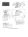
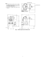
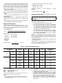
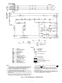
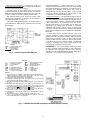
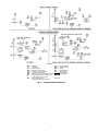
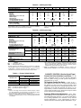
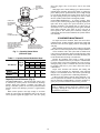
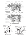
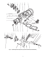
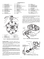
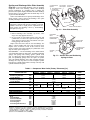
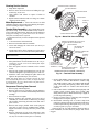
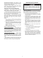
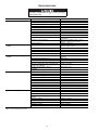
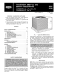
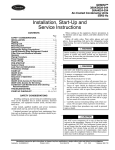
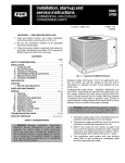
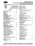
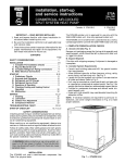
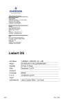
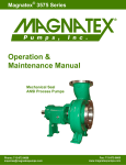
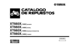
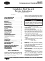
06D,07D
Compressors and Condensing Units
Installation, Start-Up and
Service Instructions
Hermetic, Water-Cooled
CONTENTS
Page
SAFETY CONSIDERATIONS . . . . . . . . . . . . . . . . . . . . . . 1
BEFORE INSTALLATION . . . . . . . . . . . . . . . . . . . . . . . . . 1
Check Shipment. . . . . . . . . . . . . . . . . . . . . . . . . . . . . . . . . . 1
Unit Location Considerations . . . . . . . . . . . . . . . . . . . . 1
INSTALLATION . . . . . . . . . . . . . . . . . . . . . . . . . . . . . . . . . 1-8
Mount Unit . . . . . . . . . . . . . . . . . . . . . . . . . . . . . . . . . . . . . . . 1
Piping Connections . . . . . . . . . . . . . . . . . . . . . . . . . . . . . . 1
Electrical Connections . . . . . . . . . . . . . . . . . . . . . . . . . . . 4
Limitations . . . . . . . . . . . . . . . . . . . . . . . . . . . . . . . . . . . . . . . 6
Refrigerant Charging . . . . . . . . . . . . . . . . . . . . . . . . . . . . . 8
INITIAL START-UP . . . . . . . . . . . . . . . . . . . . . . . . . . . . . . . . 8
To Start Compressor . . . . . . . . . . . . . . . . . . . . . . . . . . . . . 8
CHECKING OPERATION. . . . . . . . . . . . . . . . . . . . . . . . .8,9
Oil Charge. . . . . . . . . . . . . . . . . . . . . . . . . . . . . . . . . . . . . . . . 8
High-Pressure Switch . . . . . . . . . . . . . . . . . . . . . . . . . . . . 8
Low-Pressure Switch. . . . . . . . . . . . . . . . . . . . . . . . . . . . . 8
Oil Pressure Switch . . . . . . . . . . . . . . . . . . . . . . . . . . . . . . 8
Time Guard® Control. . . . . . . . . . . . . . . . . . . . . . . . . . . . . 8
CAPACITY CONTROL . . . . . . . . . . . . . . . . . . . . . . . . . .9,10
Control Set Point . . . . . . . . . . . . . . . . . . . . . . . . . . . . . . . . . 9
To Regulate Control Set Point . . . . . . . . . . . . . . . . . . . . 9
Pressure Differential Adjustment. . . . . . . . . . . . . . . . . 9
Capacity Control Pressure . . . . . . . . . . . . . . . . . . . . . . 10
CONDENSER MAINTENANCE . . . . . . . . . . . . . . . . .10,11
SERVICE . . . . . . . . . . . . . . . . . . . . . . . . . . . . . . . . . . . . . 12-17
Service Notes . . . . . . . . . . . . . . . . . . . . . . . . . . . . . . . . . . . 12
Testing Oil Pump . . . . . . . . . . . . . . . . . . . . . . . . . . . . . . . . 12
Cylinder Heads. . . . . . . . . . . . . . . . . . . . . . . . . . . . . . . . . . 14
Service Replacement Compressors . . . . . . . . . . . . . 14
Suction and Discharge Valve Plate Assembly . . . 15
Cleaning Suction Strainer . . . . . . . . . . . . . . . . . . . . . . . 16
Motor Replacement . . . . . . . . . . . . . . . . . . . . . . . . . . . . . 16
Terminal Plate Assembly . . . . . . . . . . . . . . . . . . . . . . . . 16
Compressor Running Gear Removal . . . . . . . . . . . . 16
Compressor Running Gear Replacement. . . . . . . . 17
COMPRESSOR MOTOR BURNOUT . . . . . . . . . . . . . . 17
Clean-Up Procedure. . . . . . . . . . . . . . . . . . . . . . . . . . . . . 17
TROUBLESHOOTING. . . . . . . . . . . . . . . . . . . . . . . . . .18,19
SAFETY CONSIDERATIONS
Installing, starting up and servicing this equipment can be
hazardous due to system pressures, electrical components and
equipment location (roofs, elevated structures, etc.). Only
trained, qualified installers and service mechanics should
install, start up and service this equipment.
When working on the equipment, observe precautions in the
literature, tags, stickers and labels attached to the equipment
and any other safety precautions that apply. Follow all safety
codes. Wear safety glasses and work gloves. Use care in
handling, rigging and setting bulky equipment.
Electrical shock can cause personal injury and even death.
Be sure power to equipment is shut off before installing or
servicing this equipment. There may be more than one
disconnect. Tag disconnect(s) to alert others not to turn
power on until work is completed.
BEFORE INSTALLATION
Check Shipment — File claim with shipping company
if shipment is damaged or incomplete.
Unit Location Considerations — Locate unit on
floor in a well-ventilated area. Position unit to allow sufficient
space for refrigerant and water connections and to service
compressor. Place unit so suction and discharge valves can be
easily reached and oil level checked. Do not install condensing
unit where temperature will fall below freezing.
Local water can cause excessive fouling or sealing of
condenser tubes. If such conditions are anticipated, a water
treatment analysis is recommended. Refer to Carrier System
Design Manual, Part 5, for general water conditioning
information.
Make provision in piping layout to drain and vent condenser
if system is to be shut down in winter.
INSTALLATION
Mount Unit — Level unit and bolt firmly to foundation.
Loosen compressor mounting bolts and remove shipping
blocks from under compressor. Tighten all 4 bolts on compressor. Next, loosen each bolt until the flanged washer can be
moved sideways with finger pressure.
NOTE: Be sure that compressor floats freely on mounting
springs.
Piping Connections — Attach water supply and return
lines to connections indicated on condenser unit (Fig. 1). Water
leaving condenser should not be connected directly into sewer
lines. Check local codes.
Attach refrigerant liquid and suction lines to condensing
units (Fig. 1); suction and discharge to compressor unit
(Fig. 2). When soldering or brazing piping to valves, disassemble valve or wrap it in a wet cloth to prevent heat damage.
Allow flexibility in suction line so compressor suction valve
may be moved aside for access to suction strainer.
Manufacturer reserves the right to discontinue, or change at any time, specifications or designs without notice and without incurring obligations.
PC 802
Catalog No. 530-608
Printed in U.S.A.
Form 06/07D-3SI
Pg 1
802
7-02
Replaces: 06/07D-2SI
Book 2 2 4 4
Tab 1b 2a 2b 3a
DIMENSIONS (in.)
UNIT 07D
A203
B205
A208
B210
B212
B215
WIDTH A
30
30
399/16
519/16
519/16
6313/16
NOTES:
1. For standard service practices, such as troubleshooting and refrigerant charging, allow a minimum
2′-6″ clearance around the unit.
2. Recommended service space for condenser tube
removal is one condenser length at either end.
3. For compressor removal, allow a minimum 3′ wide
access aisle to and from the unit.
4. Local codes or jurisdiction may prevail for unit
clearances.
WATER CONNECTIONS FOR 07DB215 UNIT ONLY.
Fig. 1 — 07D Condensing Unit Dimensions
2
NOTES:
1. For standard service practices, such as troubleshooting and refrigerant charging, allow a minimum
2′-6″ clearance around the unit.
2. For compressor removal, allow a minimum 3′ wide
access aisle to and from the unit.
3. Local codes or jurisdiction may prevail for unit
clearances.
Fig. 2 — 06D Compressor Unit Dimensions
3
Install a solenoid valve (field supplied) in liquid line directly
before expansion valve. Solenoid valve is necessary for single
pumpout control used on 06D, 07D units. Refrigerant filter
drier and moisture indicator are shipped with 07D condensing
units for field installation. Install in liquid line according to
manufacturer’s instructions.
Relief valve located on top of condenser (07D units) will
open to relieve excessive pressure, allowing refrigerant to
escape. Most local codes require piping from safety device to
outdoors.
Refer to Carrier System Design Manual, Part 3, for standard
piping techniques.
COMPRESSOR UNITS — Connect high- and low-pressure
switch capillary tubes from control box to compressor. See
Fig. 2.
Install discharge line muffler (accessory) in discharge line
as close to compressor shutoff valve as possible.
Determine maximum deviation from average voltage:
(AB) 236 – 233 = 3 volts
(BC) 233 – 229 = 4 volts
(AC) 234 – 233 = 1 volt
Maximum deviation is 4 volts. Determine % voltage
imbalance:
4
% Voltage Imbalance =100 x
= 1.7%
233
This amount of phase imbalance is satisfactory as it is below
the maximum allowable of 2%.
IMPORTANT: If the supply voltage phase imbalance is
more than 2%, contact your local electric utility company
immediately.
ELECTRICAL DATA NOTES
1. All 06D and 07D units are across-the-line start.
2. Wire sizes are based on TW type copper wire. Maximum
wire lengths based on data from Table 1 will result in a
1% voltage drop to compressor. Where up to 3% voltage
drop is allowed, the run length can be increased to 3 times
the length calculated from data in Table 1.
3. The 06D compressor unit electrical data shown in Table 1
does not apply for 06D compressors used as an integral
part of other Carrier equipment. See proper installation
book for electrical information.
WIRING — Power supply must correspond with unit nameplate electrical characteristics (units are internally wired at
factory for nameplate voltage). Field wiring must comply with
local and national codes.
Install a branch circuit fused disconnect of adequate size to
handle starting current.
LINE POWER — Connect line power to the compressor contactor C. For example, connect L1 to terminal 11, L2 to terminal 12 and L3 to terminal 13. See Fig. 3.
Electrical Connections
UNBALANCED 3-PHASE SUPPLY VOLTAGE — Never
operate a motor where a phase imbalance in supply voltage
is greater than 2%. Use the following formula to determine
the % voltage imbalance:
% Voltage Imbalance =
max voltage deviation from average voltage
100 x
average voltage
Example: Supply voltage is 230-3-60
AB = 236 volts
BC = 229 volts
AC = 234 volts
Average Voltage =
236 + 229 + 234
= 233 volts
3
Table 1 — Compressor Electrical Data
COMPRESSOR
PART NUMBER
06D*
VOLTAGE
(3 Ph-60 Hz)
808
M
313
818
825
A
328
537
575
208/230
460
575
208/230
460
575
208/230
460
575
208/230
460
575
208/230
460
575
208/230
460
HP
3
5
6.5
7.5
10
15
LEGEND
LRA — Locked Rotor Amps
MCC — Maximum Continuous Current
RLA — Rated Load Amps
MCC
RLA
LRA
7
17.4
8.7
10.8
27
13.5
17.6
44
22
22.2
55.5
27.8
25
62
31
32
89
40
5
12.4
6.2
7.7
19.3
9.6
12.6
31.4
15.7
15.9
39.6
19.8
17.9
44.3
22.1
22.9
63.6
28.6
28.4
71
35.5
40
100
50
64
160
80
79
198
99
91
228
114
96
266
120
MOTOR WINDING
RESISTANCE
(Ohms)
5.0
0.78
3.1
3.3
0.5
2.1
2.6
0.42
1.7
2.0
0.31
1.3
1.7
0.26
1.0
1.2
0.18
0.72
3. For wiring sizing, the RLA value can be determined by: MCC
÷ 1.56 = RLA.
4. Compressor operating amps at any specific conditions can only
be determined from a performance curve.
5. RLA values for 06D compressor protected by a calibrated
circuit breaker will depend on must-trip value of circuit breaker.
6. Ohm values shown for resistance are approximate and shown
for reference only. Motors from different vendors and motors of
different efficiencies can differ up to 15% from data shown.
7. Electrical data for compressor part numbers 06DR and
50 Hz models (not shown) are available from Carrier Sales
Representative.
*Refer to physical data table to match compressor with correct compressor unit or water-cooled condensing unit.
NOTES:
1. RLA (rated load amps) value shown is: MCC ÷ 1.40 = RLA.
2. For minimum contactor sizing, use RLA value determined by:
MCC ÷ 1.40 = RLA.
4
LEGEND
AUX
C
CH
CR
DX
EQUIP
FU
GND
HPS
IP
LLS
LPS
M3
NEC
OL
OPS
POR
SW
—
—
—
—
—
—
—
—
—
—
—
—
—
—
—
—
—
—
Auxiliary
Compressor Contactor
Crankcase Heater
Control Relay
Direct Expansion
Equipment
Fuse
Ground
High-Pressure Switch
Internal Protector
Liquid Line Solenoid Valve
Low-Pressure Switch
Cooling Tower Fan
National Electrical Code
Overload
Oil-Pressure Switch
Pumpout Relay
Start-Stop-Reset Switch
TB
TM
TR
— Terminal Block
— Timer Motor
— Timer Relay
Terminal Block Connector
Unmarked Terminal
Marked Terminal
Factory Wiring
Field Control Wiring
To indicate common potential only;
not to represent wiring.
Splice
NOTES:
1. Factory wiring is in compliance with NEC. Any field modifications
or additions must be in compliance with all applicable codes. Use
copper, copper-clad aluminum for field power supply only.
2. Field power supply wiring must be 75 C minimum.
3. Compressor thermally protected. Three-phase motors are protected against primary single-phasing condition.
4. Pilot duty control must be field supplied. Minimum contact rating
must be 25 va.
5. 60 Hz units have 120-volt control circuit. 50 Hz units have
230-volt control circuit. A separate source of supply at the correct
voltage must be field supplied through a fused disconnect device
6.
7.
8.
9.
with a maximum rating of 15 A to TB2 connections L1
(Hot Side) and L2 (Neutral).
Open control circuit disconnect switch for servicing only. Disconnect must remain closed for crankcase heater to operate.
A transformer of the following rating may be field supplied for
60 Hz units: 350 va.
Transformer must be fused and grounded per applicable codes.
If any of the original wiring furnished must be replaced, it must
be replaced with 90 C wire or its equivalent.
Fig. 3 — Unit Label Diagram — 06D,07D Units
5
Compressor Unit Connections — Extend power leads from
control center (contactor terminals) to compressor terminal box
and make connections as shown in Fig. 4.
Terminals 8 and 9 on motor terminal plate are for internal
protector connections. As shown in Fig. 4, run a wire from terminal 9 to terminal 6 on TB2 in control center and a wire from
terminal 1 on OL2 to terminal 2 on HPS in control center.
Run crankcase heater power wiring into control center.
Connect leads to terminal 5 on pumpout relay and terminal 3
on terminal block TB2. See Fig. 5.
Affix power warning label supplied in the installer’s packet
to fused disconnect which energizes crankcase heater (see unit
label diagram).
CONTROL WIRING — Control circuit power is 115 volts,
energized from an external source or from unit voltage through
field-supplied transformer. Transformer size required is 350 va
for 60 Hz units. External control power source must be
supplied through a 15-amp fused disconnect. Connect control
circuit power leads to terminal block TB2, terminals L1 and
L2. Terminal L2 is neutral potential (ground).
Compressor Protection — The 06D and 07D units are factory
wired for single-pumpout control. Field addition and wiring of
line voltage remote control and liquid line solenoid valve is
required. (See unit Fig. 3 and Fig. 6.) Remote control minimum
contact rating must be 25 va. Solenoid valve must have a
maximum load rating of 50 va holding; 200 va inrush. For
applications with cooling tower, air-cooled or evaporative
condensers, add necessary auxiliary contacts in line between
compressor contactor and terminal A1 on timer. Insert desired
interlocks and overloads between terminals 5 and 9 on terminal
block TB2.
Control wiring may be modified as shown in Fig. 6 for
automatic pumpdown control; remove low-pressure switch
between timer relay and terminal 4 on TB2. Wire low-pressure
switch between terminals 9 and 6 on TB2. Add necessary
auxiliary contacts between compressor contactor and terminal
A1 on timer. Remove wire between terminal 6 on TB2 and
terminal 3 on pumpout relay. Insert required interlocks and
overloads between terminals 5 and 9 on TB2.
LEGEND
HPS — High-Pressure Switch
OL — Overload Relay
TB — Terminal Block
Factory Wiring
Limitations — Do not use automatic pumpdown control
on direct expansion cooler applications or when compressors
are equipped with pressure-type unloader valves. Pressure
unloader valves have built-in high to low passage which allows
compressor to cycle with automatic pumpdown.
Fig. 4 — Compressor Terminal Diagram
C
CH
CR
FU
GND
HPS
IP
LPS
—
—
—
—
—
—
—
—
LEGEND
Contactor, Compressor
NEC
Crankcase Heater
OL
Control Relay
OPS
Fuse
POR
Ground Connection
SW
High-Pressure Switch
TB
Internal Protector
TM
Low-Pressure Switch
TR
—
—
—
—
—
—
—
—
National Electrical Code
Overload Relay
Oil Pressure Switch
Pumpout Relay
Switch
Terminal Block
Timer Motor
Timer Relay
NOTES:
1. Factory wiring is in compliance with NEC. Any field modifications or
additions must be in compliance with all applicable codes. Use copper,
copper-clad aluminum for field power supply only.
2. Field power supply wiring must be 75 C minimum.
3. Compressor thermally protected. Three-phase motors are protected
against primary single-phasing condition.
4. Pilot duty control must be field supplied. Minimum contact rating must
be 25 va.
5. 60 Hz units have 120-volt control circuit. 50 Hz units have 230-volt control circuit. A separate source of supply at the correct voltage must be
field supplied thru a fused disconnect device with a max rating of 15 A
to TB2 connections L1 (Hot Side) and L2 (Neutral).
6. Open control circuit disconnect switch for servicing only. Disconnect
must remain closed for crankcase heater to operate.
7. A transformer of the following rating may be field supplied for 60 Hz
units: 350 va.
8. Transformer must be fused and grounded per applicable codes.
9. If any of the original wiring furnished must be replaced, it must be
replaced with 90 C wire or its equivalent.
Fig. 5 — 06D/07D Control Box Components and Connections (3-Phase)
6
AUX
C
CR
HPS
LLS
LPS
M3
M4
M5
LEGEND
Auxiliary
OL — Overload Relay
Contactor
POR — Pumpout Relay
Control Relay
SW — Switch
High-Pressure Switch
TB — Terminal Block
Liquid Line Solenoid Valve
TR — Timer Relay
Low-Pressure Switch
Factory Wiring
Evaporator Fan or Chilled Water Pump
Field Wiring
Cooling Tower Pump, Air-Cooled or
Evaporative Condenser Fan
*Optional.
— Cooling Tower Fan or
Evaporative Condenser Pump
—
—
—
—
—
—
—
—
Fig. 6 — Recommended Field Wiring
7
Refrigerant Charging
CHECKING OPERATION
Refer to Carrier Standard Service Techniques Manual,
Chapter 2 for complete instructions on checking electrical
components.
When charging, or when removing charge, circulate water
through water-cooled condenser(s) and cooler continuously
to prevent freezing. Freezing damage is considered abuse
and is not covered by Carrier warranty.
Oil Charge (See Tables 2A and 2B) — Check oil
level in compressor sight glass after 15 to 20 minutes of
operation. If oil level is low, add oil according to methods
described in Carrier Standard Service Techniques Manual,
Chapter 1 (Section 1-11). Add oil through suction manifold
connection on 4-cylinder compressors, and oil port on
6-cylinder compressors.
The preferred method for a complete recharge is to 1/2 sight
glass with compressor shut down.
When additional oil, or a complete charge, is required, use
only Carrier-approved compressor oil.
Approved* oils are:
Witco. . . . . . . . . . . . . . . . . . . . . . . . . . . . . . . . . . . . ..Suniso 3GS
Texaco, Inc. . . . . . . . . . . . . . . . . . . . . . . . . . . . . Capella WF-32
*Oils approved for R-12, R-22, R-502 Carrier refrigerants.
For other refrigerants, contact Carrier Factory Sales
Representative.
EVACUATE, DEHYDRATE AND LEAK TEST — Entire refrigerant system must be evacuated, dehydrated and leak tested
by methods described in Carrier Standard Service Techniques
Manual, Chapter 1, Sections 1-6 and 1-7. Use sight glass method to charge system. See Section 1-8 of manual for details.
CHARGE THE SYSTEM — Charge to a clear sight glass
while holding saturated condensing pressure constant at 125 F
(air-cooled systems) or 105 F (water-cooled systems). Add
additional refrigerant to fill condenser subcooler coils, where
applicable, for air-cooled applications.
06D Compressor Units — See condenser data for additional
charge required to fill subcooler after clear sight glass is
obtained.
INITIAL START-UP
IMPORTANT: Do not reuse drained oil and do not use oil
that has been exposed to atmosphere.
Do not attempt start-up with terminal cover removed.
Bodily injury or death may result from explosion and/or
fire if power is supplied to compressor with the terminal
cover removed or unsecured. See warning label on terminal cover.
High-Pressure Switch — Check by throttling condens-
Crankcase heater should be energized a minimum of
24 hours before starting unit. Do not permit crankcase heaters
to be deenergized during normal shutdown periods.
Check to see that oil level is 1/3 to 2/3 up on compressor sight
glass.
Open water supply valve and allow water to reach condenser. Open pressure line valve of water regulating valve, if used.
(Turn condenser fan on when the compressor unit is applied
with air-cooled condenser.)
Backseat (open) the compressor suction and discharge shutoff valves; open liquid line valve at receiver.
Start evaporator fan or chilled water pump.
Low-Pressure Switch — Check by slowly closing suc-
er water or blocking airflow on air-cooled units, allowing head
pressure to rise gradually. Check discharge pressure constantly
throughout procedure. Compressor should shut off within 10 psi
of values shown in Table 3.
tion shutoff valve or by completely closing liquid line shutoff
valve. A decrease of suction pressure will follow. Compressor
should shut off within 4 psi of values shown in Table 3.
Oil Pressure Switch (OPS) — The oil pressure switch
protects against damage from loss of oil or loss of oil pressure
during unit start-up. If the oil pressure differential sensed by the
OPS is 6 psig or less on unit start-up, the switch remains closed
and the OPS heater is energized.
The switch time delay is approximately 45 seconds. If after
45 seconds the oil pressure differential sensed by the OPS is
less than 11 psig, the heater remains energized. The OPS temperature actuated switch then opens and the compressor is
deenergized. If the differential reaches 11 psig, the OPS opens
and deenergizes the heater and the system operates normally.
To Start Compressor — Close main power switch,
control power switch, and unit ON-OFF switch. Time Guard®
control circuit causes a short delay before compressor starts.
Recheck oil level and check oil pressure. See Oil Charge for
details.
With unit operating, voltage at compressor terminals must
be within limits shown on nameplate. Phases must be balanced
within 2% of voltage (refer to Electrical Connections section).
Contact local power company for correction of improper line
voltage or phase imbalance. Operation of unit on improper line
voltage or with excessive phase imbalance constitutes abuse
and is not covered by Carrier Warranty.
NOTE: The 06D, 07D unit safety controls are of the
automatic-reset type. If compressor is shut off by a safety
control, do not permit control to reset more than once before
determining cause of shutdown.
IMPORTANT: If the oil pressure switch causes unit lockout, determine and correct the cause of the lockout (such as
loss of compressor oil or flooded compressor) before
restarting the unit. Failure to correct the cause of OPS lockout may constitute abuse. Equipment failure due to abuse is
not covered by warranty.
To restart the unit, push the OPS reset button and then push
the control circuit switch on the unit control box to OFF and
then to ON.
Time Guard® Control — Control provides a delay of
approximately 5 minutes before restarting compressor after
shutdown for any reason. On starting, the Time Guard control
timer causes a delay of 15 seconds after thermostat closes
before compressor will start.
8
Table 2A — 06D Physical Data
UNIT 06D
OPERATING WEIGHT (lb)
REFRIGERANT
COMPRESSOR — 06D*
Cylinders
Bore (in.)
Stroke (in.)
Displacement (cfm at 1750 rpm)
Maximum Rpm
Oil Charge (pt)
High Side Maximum Pressure
Low Side Maximum Pressure
CONNECTIONS (in.)
Suction Valve (ODF)
Discharge Valve (ODF)
A8081
180
H3131
250
M808
2
2
11/4
8
M313
4
2
1
13
3
4.5
7/
8
5/
8
7/
8
5/
8
A8181
E8251
265
325
R-134a, R-22, R-507/404A
A818
A825
4
6
2
2
7
1 /16
11/4
18.3
23.9
1750
5.5
8
450 PSIG
245 PSIG
11/8
7/
8
→
*Compressors listed are for R-22 applications. For R-134a and R-507/
404A an 06DR compressor is standard. Factory compressor substitutes
may be made. Contact Carrier Sales Representative.
13/8
7/
8
E3281
325
E5371
330
A328
6
2
15
1 /32
28
A537
6
2
15
1 /16
37.1
8
8
13/8
7/
8
13/8
11/8
NOTE: The 06DE8251 compressor unit with the 06DA825 compressor
replaces the 06DE8241 once inventory of the 06DA824 compressor is
depleted.
Table 2B — 07D Physical Data
UNIT 07D
OPERATING WEIGHT (lb)
REFRIGERANT
COMPRESSOR — 06D*
Cylinders
Bore (in.)
Stroke (in.)
Displacement (cfm at 1750 rpm)
Maximum Rpm
Oil Charge (pt)
High Side Maximum Pressure
Low Side Maximum Pressure
CONDENSER (Shell and Tube)† Part Number
R-134a
Refrigerant Storage
Capacity (lb)
R-22
Min Refrigerant Operating
Charge (lb)
R-507/404A
REFRIGERANT CONNECTION (in. ODF)
Inlet
Outlet
WATER CONNECTION (in. FPT)
Inlet/Outlet
A203
270
B205
395
M808
2
2
11/4
8
M313
4
2
1
13
3
4.5
P701-0605CX
17.20
2.86
17.00
2.80
14.70
2.80
P701-0607CX
15.90
3.16
15.70
3.10
13.60
3.10
15/8
11/8
15/8
11/8
15/8
11/8
1
1
11/4
LEGEND
FPT — Female Pipe Thread
ODF — Outside Diameter, Female
→
*Compressor listed is the standard compressor for R-22, air conditioning
duty. An 06DR compressor is standard equipment for low temperature
(R-507/404A) or medium temperature (R-134a) applications. Factory
substitutions may be made. Contact Carrier Sales Representative.
High Pressure
Low Pressure
Oil Pressure
B212
595
B215
620
A328
6
2
115/32
28
A537
6
2
115/16
37.1
8
8
P701-0620CX
27.40
8.47
27.10
8.30
23.50
8.30
P701-0625AX
39.80
9.18
39.30
9.00
34.10
9.00
15/8
11/8
15/8
11/8
15/8
11/8
11/4
11/4
2
†The condenser listed is for R-22, air conditioning duty and may change
based on the application. Maximum condenser operating pressure:
350 psi refrigerant side, 300 psi water side (“CX” models); 350 psi
refrigerant side, 150 psi water side (“AX” models).
NOTE: The 07DB210 with the 06DA825 compressor replaces the
07DB210 with the 06DA824 once the compressor inventory is depleted.
CAPACITY CONTROL (Suction Cutoff Type)
Control Set Point (Cylinder Load Point) — Set
Table 3 — Factory Switch Settings
SWITCH TYPE
A208
B210
420
545
R-134a, R-22, R-507/404A
A818
A825
4
6
2
2
17/16
11/4
18.3
23.9
1750
5.5
8
450 PSIG
245 PSIG
P701-0610CX P701-0615CX
24.40
31.60
5.00
7.55
24.10
31.20
4.90
7.40
20.90
27.10
4.90
7.40
PRESSURE CHANGE AFFECTING
SWITCH POSITION
Closed
Open
210 (±10) (psig)
290 (±10) (psig)
70 (±4) (psig)
60 (±4) (psig)
6 (psid)
11 (psid)
point is adjustable from 0 to 86 psig. Pressure differential
between cylinder load-up point and cylinder unload point is
adjustable from 7 to 19 psi.
To Regulate Control Set Point — Refer to Fig. 7.
Turn adjustment nut clockwise to its bottom stop (with nut in
this position, set point is 86 psig). Control set point is then
regulated to desired pressure by turning adjustment nut counterclockwise. Every full turn decreases set point by 7.2 psi.
Approximately 12 turns in counterclockwise direction will decrease control set point to 0 psig. Table 4 shows steps of control
for the compressor and condensing unit.
Pressure Differential Adjustment — Turn differential adjusting screw counterclockwise to its back-stop position (differential in this position is 7 psi). Pressure differential is
set by turning adjustment screw clockwise. Every full turn
increases differential by 1.2 psi. Approximately 10 turns in
clockwise direction will increase pressure differential to 19 psi.
LEGEND
psid — pounds per square inch differential
psig — pounds per square inch gage
NOTES:
1. Values for the high- and low-pressure switches based on R-22.
For other refrigerants, reset to pressure corresponding to saturation temperatures indicated by the listed pressures.
2. Values for oil pressure are above operating suction pressure
(pressure differential between suction and discharge pressures
of oil pump).
9
802
moves the poppet valve to left and it seats in the closed
position.
With poppet valve closed, discharge gas is directed into the
unloader-piston chamber and pressure builds up against the
piston. When pressure against unloader piston is high enough
to overcome the unloader valve spring, piston moves valve to
the right, opening suction port. Suction gas can now be drawn
into the cylinders and the bank is running fully loaded.
UNLOADED OPERATION — As suction pressure drops
below set point, control spring expands, snapping diaphragm to
right. This forces poppet valve open and allows gas from
discharge manifold to vent through base of control valve to
suction side. Loss of full discharge pressure against unloaded
piston allows unloader valve spring to move valve left to
closed position. The suction port is blocked, isolating the
cylinder bank from the suction manifold. The cylinder bank is
now unloaded.
CONTROL
SET POINT
ADJUSTMENT
NUT
POWER
HEAD
PRESSURE
DIFFERENTIAL
ADJUSTMENT
SCREW
VALVE BODY
BYPASS
PISTON RING
CONDENSER MAINTENANCE
BYPASS PISTON-USED
WITH HOT GAS BYPASS
TYPE OF UNLOADING ONLY.
NOT REQUIRED WITH
SUCTION CUTOFF TYPE
UNLOADING.
To inspect and clean condenser, drain water and remove
condenser heads. To drain condenser, shut off water supply and
disconnect inlet and outlet piping. Remove drain plugs and
vent plug.
With condenser heads removed, inspect tubes for refrigerant
leaks. (Refer to Carrier Refrigerant Service Techniques Manual.)
Clean condenser tubes with nylon brush (available from
Carrier Service Department). Flush water through tubes while
cleaning. If hard scale has formed, clean tubes chemically. Do
not use brushes that will scrape or scratch tubes.
Because the condenser water circuit is usually an open
system, the condenser tubes may be subject to contamination
by foreign matter. Local water conditions may cause excessive
fouling or pitting of tubes. Condenser tubes, therefore, should
be cleaned at least once a year or more often if the water is
contaminated.
Proper water treatment can minimize tube fouling and
pitting. If such conditions are anticipated, water treatment
analysis is recommended. Refer to the Carrier System Design
Manual, Part 5, for general water conditioning information.
If hard scale has formed, clean the tubes chemically. Consult an experienced and reliable water-treatment firm in your
area for treatment recommendations. Clean the condenser by
gravity or by forced circulation as shown in Fig. 9 and 10.
DIFFERENTIAL SCREW
SEALING CAP (CAP MUST
BE REPLACED TO PREVENT
REFRIGERANT LEAKAGE)
Fig. 7 — Capacity Control Valve
(Pressure Type)
Table 4 — Capacity Control Reduction Steps
UNIT 06D,07D
ALL 4 CYLINDER
MODELS
ALL 6 CYLINDER
MODELS
% Full Load Capacity
67
49
32
% Full Load kW
100
73
57
46
Number of Active Cylinders
NO. OF
CONTR
CYL
100
2
4
—
2
—
4
6
4
—
2
Capacity Control Pressure (Fig. 8)
LOADED OPERATION — Pressure-operated control valve
is controlled by suction pressure and actuated by discharge
pressure. Each valve controls 2 cylinders (one bank). On
start-up, controlled cylinders do not load up until differential
between suction and discharge pressures is approximately
25 psi.
When suction pressure rises high enough to overcome
control set point spring, the diaphragm snaps to the left and
relieves pressure against the poppet valve. The drive spring
IMPORTANT: If the ambient temperature is below 32 F
during a shutdown period; protect the condenser from
freezing by draining the water from the system or by adding antifreeze to the water.
10
Fig. 8 — Capacity Control Valve Operation
FILL CONDENSER WITH
CLEANING SOLUTION. DO
NOT ADD SOLUTION
MORE RAPIDLY THAN
VENT CAN EXHAUST
GASES CAUSED BY
CHEMICAL ACTION.
CENTRIFUGAL PUMP 1/2 HP
30 GPM AT 35’ HEAD
PRIMING
PUMP
CONN.
1”
PIPE
GAS VENT
GLOBE
VALVES
CLOSE VENT PIPE
VALVE WHEN
PUMP IS
RUNNING
SUCTION
VENT
PIPE
PUMP
SUPPORT
5’ APPROX
1” PIPE
3’ TO 4’
CONDENSER
CONDENSER
LEGEND
REMOVE WATER
Shaft
1 — Oil Pressure Relief Valve 5 — Eccentric
REGULATING
VALVE
6 — Eccentric Strap Side
2 — Piston and Eccentric
Shield
Strap Assembly
Oil Suction Tube
3 — Motor End Counterweight 7 —
RETURN
FINE
MESH
4 — Oil Return Check Valve
8 — Pump End Counterweight
SCREEN
TANK
Fig. 11 — Compressor
Fig.(Bottom
10 — Forced
Circulation
Plate Removed)
Fig. 9 — Gravity Circulation
11
SERVICE
Testing Oil Pump — Observe oil level sight glass. The
oil pressure relief valve line is positioned to discharge oil
against sight glass. When oil does not discharge from this line,
it is an indication of low oil pump pressure.
If oil pump pressure is low, remove and check oil filter
screen, oil pressure regulator and oil return check valve.
OIL PRESSURE RELIEF VALVE (Fig. 11) — Unscrew relief valve assembly from motor partition plate, and be sure
assembly is not clogged or the plunger is not stuck.
OIL RETURN CHECK VALVE (Fig. 11) — Unscrew check
valve from motor partition plate. Be sure flutter valve is not
sticking and that it seats tightly.
OIL FILTER SCREEN (Fig. 12) — Screen is accessible
through bottom cover plate. Remove and inspect strainer for
holes and dirt. Clean it with solvent and replace.
OIL PUMP AND BEARING HEAD (Fig. 12) — The oil
pump assembly is contained in the pump end bearing head
aluminum casting. The pump end main bearing is a machined
part of this casting. An insert bearing is not required.
Remove Bearing Head Assembly from Crankcase — Remove
in sequence (refer to Fig. 12 and 13): oil pump cover, oil feed
guide retaining spring, oil feed guide, pump drive segment. If
damage to the oil pump or main bearing is found, a new pump
end bearing head assembly should be installed.
Replace (Refer to Fig. 12 and 13) — For torque values, refer
to Table 5. Following steps are used to replace bearing head:
1. Bolt bearing head to crankcase. Place pump drive segment into position and secure to end of crankshaft with
cap screws and lock washers that were removed (see
Fig. 13).
2. Insert oil feed guide with large diameter inward and place
guide retainer spring over small diameter of guide.
3. Install gasket and oil pump cover.
Do not remove the compressor terminal box cover until
all electrical power is disconnected and pressure is
relieved. Terminal pins may blow out causing injuries,
death, and/or fire.
Service Notes
1. Where compressor components are shown, they are in
normal order of removal from compressor.
2. For replacement items, use Carrier specified parts.
See Carrier 06D Specified Parts list for compressor part
interchangeability.
3. Before compressor is opened, the refrigerant must be
removed from it by the Pumpdown method.
a. Start compressor, close suction shutoff valve, and
reduce crankcase pressure to 2 psig (bypass low
pressurestat with jumper).
b. Stop compressor and isolate from system by
closing discharge shutoff valve.
c. Bleed any residual refrigerant. Drain oil if
necessary.
4. After disassembly, clean all parts with solvent. Use
mineral spirits, white gasoline or naphtha.
5. Before assembly, coat all parts with compressor oil and
clean and inspect all gasket surfaces. Replace all gaskets
with new standard specified gaskets, coated with
compressor oil. See Table 5 for typical torque values.
6. After reassembly, evacuate compressor and open suction
and discharge valves. Restart compressor and adjust
refrigerant charge.
Table 5 — Torque Values
SIZE
DIAM
(in.)
1/16
THREADS TORQUE
RANGE
USAGE
PER IN.
(lb-ft)
27 (pipe)
8-12
Pipe Plug — Crankshaft
Oil Return Check Valve —
1/8
20 (pipe)
6-10
Crankcase
20 (pipe)
20-25
Pipe Plug — Press. Gage Conn.
20
10-12
Connecting Rod Capscrew
1/4
12-15
Baffle Plate — Crankcase
12-15
Side Shield
28
12-15
Oil Pump Drive Segment
12-15
Unloader Valve
Cover Plate — Pump End
16-20
Bearing Head
5/
18
16-20
Terminal Block Cap Screws
16
20-25
Suction Service Valve
20-25
Discharge Service Valve
30-35
Pump End Bearing Head
30-35
Bottom Plate — Crankcase
3/8
16
30-35
Compressor Foot
30-35
Cylinder Head
30-35
Motor End Cover — Crankcase
7/16
14
55-60
Motor End Cover — Crankcase
1/2
13
80-90
Suction Service Valve
5/
11
25-30
Crankshaft Spinner Tube
8
32
4- 6
Oil Pump Drive Segment
No. 10
11/2
18 NEF
35-45
Oil Level Sight Glass
1
2
8
7
3
4
6
1 —
2 —
3 —
4 —
5
LEGEND
Oil Pressure Relief Valve 5 —
Piston and Eccentric
6 —
Strap Assembly
Motor End Counterweight 7 —
Oil Return Check Valve
8 —
Eccentric Shaft
Eccentric Strap Side
Shield
Oil Suction Tube
Pump End Counterweight
Fig. 11 — Compressor
(Bottom Plate Removed)
LEGEND
NEF — National Extra Fine
12
8
7
6
5
4
3
26
2
9
10
11
1
12
25
24
13
23
22
PHASE BARRIER
POSITIONING
KEY (SEE FIG. 19)
14
43
44
42
41
40
39
15
16
17
16
18
38
19
37
20
36
35
21
34
33
32
31
30
29
28
15
45
46
47
48
49
Fig. 12 — 06D Compressor Components (4-Cylinder with Eccentric Shaft Shown)
13
27
LEGEND FOR FIG. 12
1
2
3
4
5
6
7
8
—
—
—
—
—
—
—
—
9
10
11
12
13
14
—
—
—
—
—
—
15 —
16 —
Motor Cover Gasket
Motor End Cover
Discharge Manifold Connection
Valve Plate Gasket
Valve Plate Assembly
Cylinder Head Gasket
Cylinder Head
Cylinder Head Washer
and Cap Screw
Suction Manifold Connection*
Suction Valve Positioning Spring
Suction Strainer
Bearing Head Gasket
Oil Pump Inlet Passage
Bearing Head Washer
and Cap Screw
Oil Pump Cover
Pump End Bearing Head
17
18
19
20
21
22
23
24
25
26
—
—
—
—
—
—
—
—
—
—
27
28
29
30
31
32
33
—
—
—
—
—
—
—
Oil Drain Plug
Crankcase
Bottom Plate Gasket
Bottom Plate
Bottom Plate Washer and Cap Screw
Oil Filter Screen
Oil Return Check Valve
Oil Level Sight Glass
Motor Terminal Plate
Dowel Pins (For Suction Valve
Positioning)
Equalizing Tube and Lock Screw Assembly
Lockwasher
Rotor Lockwasher
Rotor Drive Key
Piston Pin Lock Ring
Piston Pin
Piston
—
—
—
—
—
—
—
Three Allen head cap screws hold capacity control valve in
place (Fig. 14). Remove screws using a cut-down 3/16-in. Allen
wrench, and pull valve from cylinder head.
Remove same number of piston plugs from replacement
compressor as number of unloaders supplied with original
compressors. Three Allen head cap screws hold piston plug
assembly in place. Remove flange cover, gasket, spring and
bypass piston plug (Fig. 15). A tapped hole is provided in
piston to allow it to be pulled out. Hole has same thread
diameter as cap screws removed above.
1
2
TOP
Oil Ring
Compression Rings
Eccentric Strap
Eccentric Strap Side Shield
Pump End Counterweight
Oil Pump Drive Segment
Drive Segment Cap Screws
and Lockwashers
41 — Oil Feed Guide
42 — Oil Feed Guide Retainer Spring
43 — Cover Gasket
44 — Pump Cover Cap Screw and Washer
45 — Counterweight Bolt
46 — Eccentric Strap Side Shield
47 — Motor End Counterweight
48 — Locknut
49 — Eccentric Shaft (or Crankshaft)
*Used to add compressor oil.
34
35
36
37
38
39
40
3
4
5
8
CAPACITY
CONTROL
VALVE
6
7
LEGEND
1
2
3
4
— Suction Strainer
Assembly
— Oil Pump Bearing Head
Assembly
— Rotor Retaining Ring
— Oil Pump Drive Segment
5
6
7
8
CAP SCREWS
(NONINTERCHANGEABLE
WITH FLANGE COVER
CAP SCREWS)
— Oil Pump Rotor
— Drive Segment Cap
Screws
— Bearing Head Cap
Screws
— Oil Pump Inlet Passage
Fig. 14 — Removal of Capacity Control Valve
Fig. 13 — Removing Pump End Bearing Head
BYPASS PISTON PLUG
Cylinder Heads — Disassemble cylinder heads by removing cap screws and prying up on side between cylinder
head and valve plate to break heads loose from valve plate. Do
not strike cylinder heads to break loose.
Check heads for warping, cracks and damage to gasket
surfaces. When replacing cylinder head, torque cap screws
30 to 35 lb-ft to prevent high to low side leak in center portion
of cylinder head gasket.
SPRING
CAP SCREWS
(NONINTERCHANGERABLE
WITH CONTROL VALVE
CAP SCREWS)
Service Replacement Compressors — Replacement compressors are not equipped with control valves. One or
both side bank cylinder head(s) is plugged with a spring loaded
plug piston assembly. Compressor will run fully loaded with
piston plug(s) in place.
Transfer original capacity control valve(s) to replacement
compressor (ensures proper valves are used with correct setting). For sealing purposes, install a plug piston assembly into
each cylinder head of original compressor from which a control valve was removed.
TAB
GASKET
GAS PORT
FLANGE COVER
Fig. 15 — Removal of Bypass Piston Plug
14
Suction and Discharge Valve Plate Assembly
(Fig. 16) — Test for leaking discharge valves by pumping
CYLINDER HEAD
GASKET
compressor down and observing suction and discharge
pressure equalization. If a discharge valve is leaking, the
pressures will equalize rapidly. Maximum allowable discharge
pressure drop is 3 psi per minute after an initial drop of 10 to
15 psi in the first half minute.
If there is an indicated loss of capacity and discharge valves
check properly, remove suction and discharge valve plate
assembly and inspect suction valves.
DISCHARGE
VALVE STOP
VALVE PLATE
GASKET
DISCHARGE VALVE
SCREW AND
LOCK WASHER
DISCHARGE
VALVE
VALVE PLATE
IMPORTANT: This test procedure is not applicable to
compressors equipped with pressure actuated or solenoid
unloader valves due to rapid pressure equalization rate.
Check suction and discharge valves by disassembling
valve plate (see Fig. 16).
VALVE PLATE ASSEMBLY
Fig. 16 — Valve Plate Assembly
DISASSEMBLY — Remove cylinder head.
1. Remove discharge valve assembly: cap screws, valve
stops, valve stop supports and valves.
2. Pry up on side of valve plate, between valve plate and
cylinder deck, to remove valve plate and expose suction
valves. Remove suction valves and suction valve positioning springs from dowel pins.
Inspect valves and valve seats for wear and damage. See
Table 6. Check cylinder deck valve stops for uneven wear.
Replace valves if cracked or worn. If valve seats are worn,
replace complete valve plate assembly. If cylinder deck valve
stops are worn, replace compressor.
REASSEMBLY — Do not interchange valves. Install suction
valve positioning springs on dowel pins. Assemble positioning
springs with spring ends bearing against cylinder deck
(Fig. 17). Springs bow upward. Place suction valves on dowel
pins, over positioning springs. Place valve plate on cylinder
deck, and reinstall discharge valve plate assembly. Retorque
discharge valve stop cap screws to 16 lb-ft. Replace cylinder
head. Be sure cylinder head gasket is lined up correctly with
cylinder head and valve plate.
DISCHARGE
PORT
HIGH-PRESSURE
CONNECTION
VALVE PLATE
DOWEL PIN
LOW-PRESSURE
CONNECTION
SUCTION VALVE
POSITIONING
SPRING
SUCTION
VALVE
Fig. 17 — Suction Valve and Positioning
Springs in Place
Table 6 — Compressor Wear Limits (Factory Tolerances) (in.)
COMPRESSOR PART
MOTOR END
Main Bearing Diameter
Journal Diameter
PUMP END
Main Bearing Diameter
Journal Diameter
CRANKPIN DIAMETER
THROW
THRUSTWASHER
ECCENTRIC DIAMETER
CONN. ROD DIAMETER
PISTON PIN BEARING
CYLINDERS
Bore
Piston Diameter
Piston Pin Diameter
Piston Pin Bearing
Piston Ring Gap
Piston Ring Side Clearance
06DM808
Max
Min
Max
Min
Min
Max
Min
Max
Min
Max
Max
Min
06DM313
COMPRESSOR MODEL
06DA818
06DA825†
1.3755
1.3735
1.3745
1.3735
1.3735
2.2030
1.4374
1.2500
1.4344
1.246
2.2030
1.2500
1.0000
1.2460
—
—
—
2.2035
—
—
1.3755
2.2035
—
0.6878
2.0005
1.996
0.6873
Press Fit
0.0130
0.0050
0.0020
0.0010
Max
Min
Min
Max
Min
Max
Min
*Maximum allowable wear above maximum or below minimum factory tolerances
shown. For example: difference between pump end main bearing diameter and
journal diameter is .001 in. (1.3745 – 1.3735) per factory tolerances. Maximum
allowable difference is .004 in. (.002 + .002).
†Tolerance for the 06DA825 same as 06DA824.
15
06DA328
06DA537
MAX* ALLOW
WEAR
1.6240
1.6233
0.002
0.002
—
0.1570
0.1550
0.002
0.002
0.0025
—
—
0.025
0.025
0.002
0.002
0.001
1.3735
1.9396
—
—
1.3755
0.002
0.002
0.001
—
0.025
0.025
0.002
0.002
Cleaning Suction Strainer
STRAINER SCREWS & WASHERS
1. Pump down compressor.
2. Remove motor end cover and screws holding disc type
strainer (Fig. 18) to cover.
3. Clean strainer with solvent or replace if broken or
corroded.
4. Replace strainer and motor end cover. Purge or evacuate
compressor before starting.
SUCTION STRAINER
MOTOR END COVER
VALVE GASKET
VALVE CAP
SCREW
Motor Replacement — Stator and rotor are not field
replaceable. Stator is a press fit into motor housing. If compressor motor is damaged, replace compressor.
Terminal Plate Assembly — The terminal plate assembly is shown in Fig. 19. Do not disassemble for any reason except to replace the phase barrier, which may become damaged.
If refrigerant leakage or a ground short occurs, the entire terminal plate assembly must be replaced.
If it becomes necessary to remove the phase barrier, proceed
as follows:
1. Loosen and remove all terminal nuts.
2. Remove lock washers and wire terminals.
3. Loosen and disengage the center screw. (Do not try to
remove the screw.)
4. Lift the phase barrier off the terminal screws (the spacers
and the center screw are removed with the phase barrier).
SUCTION SERVICE VALVE
Fig. 18 — Motor End Cover Assembly
BARRIER POSITIONING KEY (THIS SIDE IS
ADJACENT TO THE CYLINDER HEAD)
PHASE BARRIER
NO TERMINAL IN
THIS SECTION
TERMINAL NUMBERS ON
THIS SURFACE
IMPORTANT: Do not disturb the jam nuts on which the
phase barrier rests.
TERMINAL
NUT(TYP)
Procedure for reassembling the phase barrier:
1. Place phase barrier over the terminal screws. Be sure positioning key is in the recess in the terminal plate before
proceeding further.
2. Place the spacers and wire terminals on the terminal
screws.
3. Place the lock washers and terminal nuts over the wire
terminals and tighten to specified torque (18 to 30 lb-in.).
4. Install the center screw through the phase barrier and
tighten to the specified torque (15 to 25 lb-in.).
NOTE: The design allows for clearance between the center
screw head and the phase barrier. Thus, the torque limit may
be reached before the screw head contacts the phase barrier.
This condition is acceptable.
BLACK JAM NUTS
ON TERMINALS 8 & 9;
BRASS JAM NUTS ON
TERMINALS 1, 2 AND 3
SPACER
(TYP)
CENTRAL SCREW (THREADS
INTO TERMINAL PLATE)
LOCK WASHER
(TYP)
ACROSS-THE-LINE APPLICATION (5 TERMINALS)
Fig. 19 — Terminal Plate Assembly
7. Remove bolts holding counterweights and eccentric strap
side shields to eccentric shaft. Remove eccentric strap
side shields. Remove pump end counterweight through
pump end bearing head opening. Motor end counterweight will remain on eccentric shaft until shaft is
removed.
8. Pull eccentric shaft or crankshaft out through pump end
opening. Guide eccentric straps from eccentric shaft
during removal process. Rotate shaft and tap it lightly to
prevent straps from jamming.
9. Remove eccentric straps or connecting rods and pistons
through bottom cover plate opening.
10. Disassemble connecting rods or eccentric straps from
pistons by removing lock ring(s) and piston pins. Remove
oil and compression rings from piston. Keep each piston
assembly together for proper reassembly.
Check all parts for wear and tolerances shown in Table 6.
Check crankshaft (eccentric shaft) oil passages and clean if
clogged.
Compressor Running Gear Removal
1. Remove pump end bearing head.
2. Remove motor end cover carefully to prevent damage to
stator. Support cover and lift off horizontally until it clears
windings.
3. Remove bottom cover plate.
4. Remove equalizer tube assembly from motor end of
crankshaft (or eccentric shaft). If shaft turns, preventing
tube assembly from being loosened, block shaft with a
piece of wood.
5. Remove rotor using a jackbolt. Insert a brass plug into
rotor hole to protect end of crankshaft from jackbolt.
Support rotor while it is being removed to prevent stator
damage.
6. Remove connection rod caps from compressors using
connecting rods and crankshafts. Label caps and rods so
they may be reinstalled in same plate on crankshaft.
16
COMPRESSOR MOTOR BURNOUT
PUMP END MAIN BEARING — This bearing is a machined part of the new aluminum oil pump and bearing head
casting. Disassemble bearing head. If bearing is scored or
worn, replace complete bearing head.
CRANKCASE AND MOTOR END MAIN BEARINGS — These bearings are not field replaceable. If bearings
are worn or damaged, replace compressor.
Do not attempt start-up with terminal cover removed.
Bodily injury or death may result from explosion and/or
fire if power is supplied to compressor with the terminal
cover removed or unsecured. See warning label on terminal cover.
Compressor Running Gear Replacement
CRANKSHAFT — Install crankshaft through pump end,
carefully guiding it through main bearings. Replace rotor.
Attach equalizer tube assembly to motor end of shaft.
Eccentric shafts must be installed after piston assemblies.
Place motor end counterweight on shaft before inserting shaft
into compressor. See Piston Assembly Replacement.
PISTON ASSEMBLY — Attach connecting rods or eccentric
straps to pistons with piston pins and lock in place with piston
pin lock rings. Place lock rings with gap on the side.
They should be tight enough so they cannot be rotated by
finger pressure.
RINGS
1. Check ring gap by inserting each ring separately in
cylinder, approximately 3/8 in. from top. Ring gap should
be between .013 and .005 inch.
2. Install compression rings in top piston grooves with side
marked “Top” toward piston head. Install oil ring below
compression ring with notched end on bottom. Stagger
ring gaps around piston.
3. Measure side clearance between ring and piston
(Table 6). Check for free action.
PISTON ASSEMBLY REPLACEMENT
Compressors Using Crankshafts — Install connecting rod
and piston assemblies into cylinders. Place chamfered sides of
connecting rods against radius of crankpins. Install connecting
rod caps to matching connecting rods through bottom of crankcase. Be sure chamfered sides of caps are against radius of
crankpins. Caps are locked in place with cap screws. Use 8 to
10 lb-ft to tighten cap screws.
Compressors Using Eccentric Shafts — Install eccentric
strap and piston assemblies into cylinders. Install eccentric
shaft through pump end, carefully guiding it through
eccentric straps and main bearings. Install pump end counterweight to eccentric shaft and replace eccentric strap side
shields.
Turn crankshaft or eccentric shaft to be sure there is no
binding between bearing surfaces and journals. Replace oil
screen, bottom cover plate, valve plates and cylinder heads.
Clean-Up Procedure — If a hermetic motor burns out,
the stator winding decomposes, forming carbon, water and acid
which contaminate refrigerant systems. Remove these contaminants from system to prevent repeat motor failures.
1. Close compressor suction and discharge service valves,
and bleed refrigerant from compressor. Save remaining
refrigerant in system.
2. Check control box for welded contactor contacts, welded
overload contacts or burned out heater elements. Check
terminal plate for burned or damaged terminals, insulation, and shorted or grounded terminals. Repair or replace
where necessary.
3. Remove suction and discharge shutoff valve bolts and all
other connections to damaged compressor. Remove
damaged compressor and replace with new compressor.
Replace liquid line filter drier with a drier of one size
larger.
4. Purge new compressor. Triple-evacuate, using the following procedure:
a. Evacuate to 5000 microns.
b. Break vacuum with system refrigerant. Pressurize
to 15 psig. Wait 20 minutes to remove moisture.
c. Re-evacuate to 5000 microns.
d. Repeat Step b.
e. Evacuate to 1000 microns or below if possible.
5. Place compressor in operation. After 2 to 4 hours of
operation, check compressor oil for signs of discoloration
and/or acidity. If oil shows signs of contamination,
replace oil charge, filter driers, and clean suction strainer
with solvent. Repeat this procedure until oil stays clean
and acid free for 48 hours of operation.
17
TROUBLESHOOTING
Read Safety Considerations on page 1 before proceeding
with troubleshooting.
PROBLEM
Compressor does not run.
CAUSE
Main power line open.
Safety thermostat tripped.
Condenser water pump not running — power off.
Pump binding.
Incorrect wiring.
Motor burned out.
Control stuck open.
Loose terminal connection.
Improperly wired controls.
Low line voltage.
Compressor motor defective.
Compressor cycles on low-pressure
control.
Compressor cycles on high-pressure
control.
Insufficient capacity.
Unit operates long or continuously.
Seized compressor.
Low-pressure control erratic in action.
Suction shutoff valve partially closed.
Low refrigerant charge.
Plugged suction strainer.
Defective TXV.
High-pressure control erratic in action.
Discharge valve partially closed.
Air in system.
Condenser scaled (or airflow restricted).
Receiver not properly vented, refrigerant backs
up into evap condenser.
Condenser water pump or fans not
operating.
Refrigerant overcharge.
Low refrigerant charge.
Control set too high.
Expansion valve plugged.
Inefficient compressor.
Expansion valve setting too high.
Iced or dirty evaporator.
Evaporator too small.
Condensing unit too small.
Expansion valve too small.
Restricted or small gas lines.
Low refrigerant charge.
Control contacts fused.
Air in system.
Partially plugged or plugged expansion valve or
strainer.
Defective insulation.
Service load.
Inefficient compressor.
Condenser scaled.
Restricted evaporator air.
LEGEND
TXV — Thermostatic Expansion Valve
18
REMEDY
Replace fuse or reset circuit breaker.
Reset thermostat.
Restart.
Free pump.
Rewire.
Replace.
Replace control.
Check connections.
Check wiring and rewire.
Check line voltage — determine location of
voltage drop.
Check motor winding for open or short.
Replace compressor if necessary.
Replace compressor.
Raise differential setting, check capillary for
pinches, replace control.
Open valve.
Add refrigerant.
Clean strainer.
Replace.
Check capillary tube for pinches. Set control as
required.
Open valve.
Purge.
Clean condenser.
Repipe as required.
Start pump or fans.
Purge.
Add refrigerant.
Reset control.
Clean or replace.
Check valves and pistons.
Lower setting.
Defrost or clean.
Add surface or replace.
Add unit or replace.
Raise suction pressure with larger valve.
Clear restriction or increase line size.
Add refrigerant.
Replace control.
Purge.
Clean or replace.
Replace or repair.
Keep doors and windows closed.
Check valves.
Clean condenser.
Defrost coil, clean filters and ductwork.
PROBLEM
System noises.
CAUSE
Piping vibration.
Expansion valve hissing.
Compressor noisy.
Compressor loses oil.
Frosted suction line.
Hot liquid line.
Frosted liquid line.
Frosted expansion valve.
Insufficient compressor oil.
Leak in system.
Plugged or stuck compressor oil return
check valve.
Oil trapping in line.
Crankcase heaters not energized during
shutdown.
Expansion valve admitting excess
refrigerant.
Shortage of refrigerant.
Receiver shutoff valve partially closed or
restricted.
Restricted catchall.
Restricted strainer drier.
Ice plugging TXV orifice.
Moisture indicated by increase in suction
pressure.
Plugged TXV strainer.
LEGEND
TXV — Thermostatic Expansion Valve
19
REMEDY
Support piping as required, check for loose pipe
connectors.
Add refrigerant, check for plugged liquid line
strainer.
Check valve plates for valve noise, replace
compressor (worn bearings), check for loose
compressor holddown bolts.
Add oil.
Repair leak.
Repair or replace.
Check piping for oil traps.
Replace heaters.
Adjust expansion valve.
Repair leak and recharge.
Open valve or remove restriction.
Replace.
Replace.
Apply hot wet cloth to TXV.
Install drier.
Clean strainer or replace TXV.
Copyright 2002 Carrier Corporation
Manufacturer reserves the right to discontinue, or change at any time, specifications or designs without notice and without incurring obligations.
PC 802
Catalog No. 530-608
Printed in U.S.A.
Form 06/07D-3SI
Pg 20
802
7-02
Replaces: 06/07D-2SI
Book 2 2 4 4
Tab 1b 2a 2b 3a